#45 perplexing variable frequency drive vibration … variable frequency drive vibration problems...
TRANSCRIPT
PERPLEXING VARIABLE FREQUENCY DRIVE VIBRATION PROBLEMS
Brian Howes1
1Beta Machinery Analysis Ltd., Calgary, AB, Canada, T3C 0J7
ABSTRACT Several unusual vibration problems have been seen recently that involve variable frequency drives and different types of driven equipment. The drives and motors are from different manufacturers and vary widely in size. The vibrations seem to be consistent in that there is a vibration frequency that remains constant as the shaft speed of the motor changes. Sometimes the vibrations are seen in accelerometer readings, but more consistently the vibrations are torsional. Generally, the solutions have involved changes to the software in the VFD control system. 1. INTRODUCTION Recently, we have seen several vibration problems associated with variable frequency drives (VFDs). The common symptoms are:
• A fixed frequency of vibration (either torsional or linear/lateral/transverse), independent of shaft speed,
• Amplification of torsional vibrations, particularly on the motor side of the system. Significant time has been spent troubleshooting some of these cases, only to find out that simple changes to the software in the VFD control system were available to eliminate the problems. 2. CASE HISTORY 1
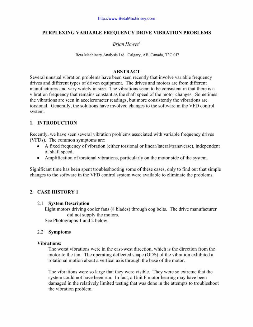
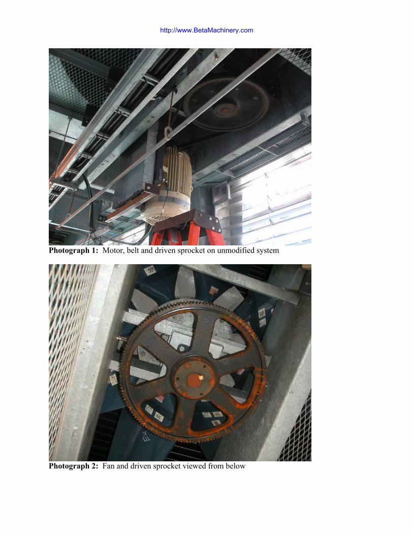
2.1 System Description Eight motors driving cooler fans (8 blades) through cog belts. The drive manufacturer
did not supply the motors. See Photographs 1 and 2 below.
2.2 Symptoms
Vibrations:
The worst vibrations were in the east-west direction, which is the direction from the motor to the fan. The operating deflected shape (ODS) of the vibration exhibited a rotational motion about a vertical axis through the base of the motor.
The vibrations were so large that they were visible. They were so extreme that the system could not have been run. In fact, a Unit F motor bearing may have been damaged in the relatively limited testing that was done in the attempts to troubleshoot the vibration problem.
http://www.BetaMachinery.com
Photograph 1: Motor, belt and driven sprocket on unmodified system
Photograph 2: Fan and driven sprocket viewed from below
http://www.BetaMachinery.com
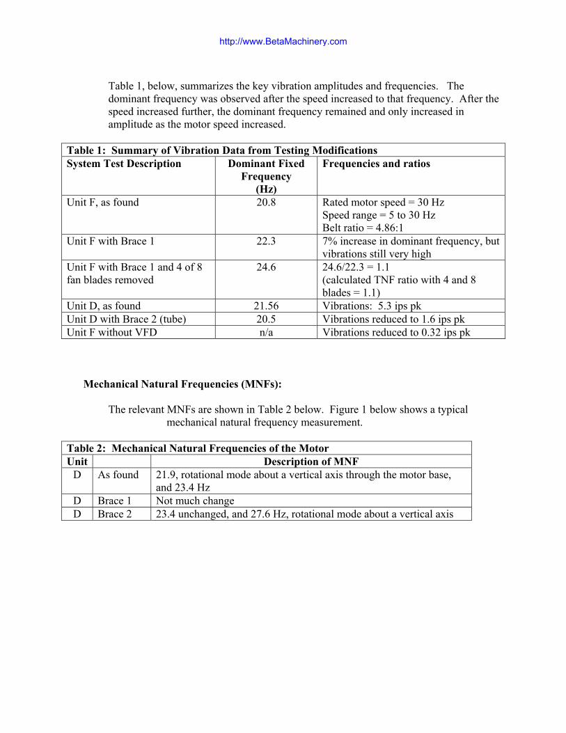
Table 1, below, summarizes the key vibration amplitudes and frequencies. The dominant frequency was observed after the speed increased to that frequency. After the speed increased further, the dominant frequency remained and only increased in amplitude as the motor speed increased.
Table 1: Summary of Vibration Data from Testing Modifications System Test Description Dominant Fixed
Frequency (Hz)
Frequencies and ratios
Unit F, as found 20.8 Rated motor speed = 30 Hz Speed range = 5 to 30 Hz Belt ratio = 4.86:1
Unit F with Brace 1 22.3 7% increase in dominant frequency, but vibrations still very high
Unit F with Brace 1 and 4 of 8 fan blades removed
24.6 24.6/22.3 = 1.1 (calculated TNF ratio with 4 and 8 blades = 1.1)
Unit D, as found 21.56 Vibrations: 5.3 ips pk Unit D with Brace 2 (tube) 20.5 Vibrations reduced to 1.6 ips pk Unit F without VFD n/a Vibrations reduced to 0.32 ips pk
Mechanical Natural Frequencies (MNFs):
The relevant MNFs are shown in Table 2 below. Figure 1 below shows a typical
mechanical natural frequency measurement.
Table 2: Mechanical Natural Frequencies of the Motor Unit Description of MNF
D As found 21.9, rotational mode about a vertical axis through the motor base, and 23.4 Hz
D Brace 1 Not much change D Brace 2 23.4 unchanged, and 27.6 Hz, rotational mode about a vertical axis
http://www.BetaMachinery.com
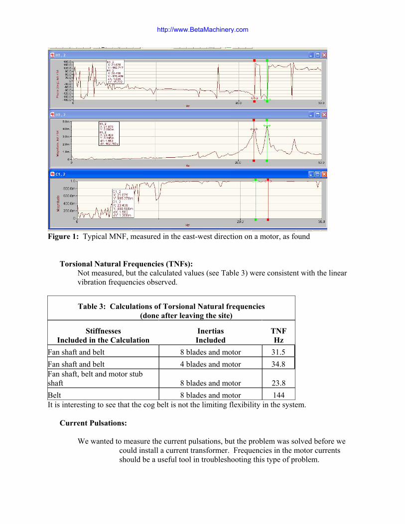
Figure 1: Typical MNF, measured in the east-west direction on a motor, as found
Torsional Natural Frequencies (TNFs):
Not measured, but the calculated values (see Table 3) were consistent with the linear vibration frequencies observed.
Table 3: Calculations of Torsional Natural frequencies (done after leaving the site)
Stiffnesses Included in the Calculation
Inertias Included
TNF Hz
Fan shaft and belt 8 blades and motor 31.5 Fan shaft and belt 4 blades and motor 34.8 Fan shaft, belt and motor stub shaft 8 blades and motor 23.8 Belt 8 blades and motor 144 It is interesting to see that the cog belt is not the limiting flexibility in the system.
Current Pulsations: We wanted to measure the current pulsations, but the problem was solved before we
could install a current transformer. Frequencies in the motor currents should be a useful tool in troubleshooting this type of problem.
http://www.BetaMachinery.com

2.3 Mechanical Changes Attempted • Brace 1
This brace was installed before we arrived. It did not make much difference to the vibrations. The dominant frequency increased about 7%, as discussed above.
Photograph 3: The photograph above shows one side of the bracing. The stiffening was
primarily in the north-south direction.
http://www.BetaMachinery.com

• Brace 2 This brace was designed to increase the stiffness in the rotational direction about a vertical axis. It was quite effective, and the vibrations were reduced dramatically, but not enough to be acceptable. The dominant or fixed frequency of vibration actually went down by about 7% with this brace installed.
Photograph 4: Looking west at the rotationally stiff brace on motor D
• Remove 4 Blades One of the tests that were done before we arrived, was to remove half of the fan blades. The only obvious effect of this change was to raise the torsional natural frequency of the system, as discussed above. The dominant frequency of the vibration increased in the same ratio as the calculated TNFs changed. The vibrations were still very high.
• Remove Belt
A motor was run alone. The vibrations were very low.
• Remove VFD Unit F motor was run without the VFD. This took some time to arrange as a starter had to be located and installed. The vibrations were acceptably low. This was the same as the manufacturer of the cooler reported when a motor-fan was tested in the factory without a VFD.
http://www.BetaMachinery.com

2.4 Electrical or Software Changes: The pulse frequency was changed from 1.5 to 3.5 kHz, based on advice over the telephone from the drive manufacturer’s representative. Subtle changes in the vibrations were noted, but the changes were of no practical significance.
The “load reactor” was removed from the electrical system, but no changes resulted.
The load reactor was returned, and the “line filter” was removed. The effect of this change was dramatic. The vibrations on the motor dropped to an acceptable level. Unfortunately, the line filter is required to protect the motor from overheating due to the harmonics in the power system.
The drive manufacturer had a software change available to correct the problem. This was installed and after some adjustments of parameters, the vibration problem went away.
2.5 Conclusions The presence of a torsional natural frequency in the system, in an apparently critical frequency range, caused motor speed fluctuations that sent current fluctuations from the motor to the VFD. The VFD and the electrical system combined to amplify the current fluctuations.
The mechanical natural frequency of the motor further amplified the vibrational response of the system.
Although the mechanical system responses had a significant effect on the frequency and amplitude of the vibrations, the fundamental cause of the high vibrations was a feed-back of energy from the VFD.
http://www.BetaMachinery.com

3. CASE HISTORY 2
3.1 System Description Two pipeline reciprocating compressors driven by synchronous motors. There is a large flywheel between the motor and the compressor. One VFD shared between the two motors, used as a soft start for the first motor which is switched to “across the line”, and then the second unit is started and run on the VFD.
The drive manufacturer did not supply the motors.
3.2 Symptoms Failures:
Several motor shaft failures in the stub shaft area have occurred, caused by torsional vibrations and improper shaft materials.
Vibrations:
Bearing housing vibrations are not high. Torsional vibrations (TVs) are an issue on the motor side of the flywheel. TVs are lower than predicted on the outboard end of the compressor, but higher than predicted on the outboard end of the motor.
The original symptoms were exhibited in the Unit 1 motor. As the speed was increased and the first torsional critical speed was excited, the TVs peaked and then stayed high at the TNF even though the motor speed was still increasing.
Unit 2 did not exhibit the “lock-in” TV at a fixed frequency. The amplitude of the TVs on the motor outboard was higher than predicted.
Mechanical Natural Frequencies:
Not an issue in this case.
Torsional Natural Frequencies (TNFs): The TNF measured in the field is as predicted using computer models. The damping used in the predictions is consistent with the damping measured in the field.
Current Pulsations:
Not measured correctly.
3.3 Mechanical Changes Attempted The motor shaft material problems have been corrected. This has had no effect on the vibrations, but will give better motor life.
3.4 Electrical or Software Changes In a recent test, the VFD manufacturer made software changes to the drive. We are not privy to the changes made.
http://www.BetaMachinery.com

The result of the changes was that the two motors now behave the same when on VFD control. The lock-in constant frequency of TV no longer occurs on Unit 1.
The amplitude of TV at resonance is higher than predicted on both units at the front of the motor.
3.5 Conclusions We believe that the compressor torque fluctuations cause speed fluctuations in the motor, which lead to current fluctuations being generated by the motor and sent to the VFD. The VFD then amplifies the current fluctuations which cause larger speed fluctuations (another way of saying torsional vibrations) in the motor.
The flywheel apparently isolates the compressor from the torsional vibrations (torque fluctuations) coming from the motor. It was originally installed to isolate the motor from torque fluctuations coming from the compressor.
Designers of torsional systems can only assume that Variable Frequency Drives will not amplify the torsional vibrations in a system at this time. In fact, we have seen that amplification does occur. Therefore, the VFD manufacturer must be made responsible for tuning the drive to match the electrical and mechanical system characteristics, eliminating the amplification.
http://www.BetaMachinery.com

4. CASE HISTORY 3 4.1 System Description
Four Vertical Motors and Pumps. The drive manufacturer supplied the motor.
4.2 Symptoms Vibrations:
Vibrations on the motor bearing housings show a fixed “lock-in” frequency at 19.75 Hz. This frequency stays constant as the shaft speed passes 19.75 Hz. Occasional trips have been occurring due to high vibrations in the NDE motor bearing accelerometer on one of the units. Monitoring of the motor has not picked up a trip yet. It is suspected that the 19.75 Hz component increases when the trip occurs, although other problems may be present. The amplitudes of vibration vary among the 4 units with the highest to lowest varying in proportion to the distance from the VFD.
Critical Speed:
The lateral critical speed of the motor-pump system is not known, although it is suspected that it is at 19.75 Hz.
Mechanical Natural Frequencies:
These are not known at this time.
Torsional Natural Frequencies: The third mode of the system is at 6 times 19.75 Hz. This TNF has not been measured yet.
Current Pulsations:
Not measured yet.
4.3 Mechanical Changes Attempted None have been made so far.
4.4 Electrical Changes None have been made so far. The manufacturer has not yet been contacted.
4.5 Conclusions Based on other experiences with VFD vibration problems, the VFD manufacturer should be contacted and requested to tune the operating parameters of the system to eliminate the unusual vibrations.
Strange vibration problems causing machine trips will go away when a monitoring system is attached to a machine.
http://www.BetaMachinery.com

5. CASE HISTORY 4
5.1 System Description Electric motor driving a centrifugal compressor. The drive manufacturer supplied the motor.
5.2 Symptoms Vibrations:
Not known, but presumably high.
Mechanical Natural Frequencies: Not known.
Torsional Natural Frequencies:
Not known.
Current Pulsations: Not known.
5.3 Mechanical Changes Attempted Not known.
5.4 Electrical and/or Software Changes The drive control scheme was changed from voltage-speed to vector. This was a software change, presumably.
5.5 Conclusions The vibration problem went away.
The cause of the problem was the Variable Frequency Drive.
5.6 Discussion The drive manufacturer initially refused to accept that the drive was the cause of the problems. Later a new representative of the drive manufacturer was able to change the “operating parameters” of the drive to solve the problem.
http://www.BetaMachinery.com

6. CONCLUSIONS
• Three of the four VFD manufacturers in these cases were reluctant to admit that mechanical vibration problems can be caused by the electrical side of the system. This experience suggests that most VFD manufacturers will behave the same way.
• A system approach to the design of a drive-motor-driven machine may be helpful. The system should include an understanding of the torsional response of the mechanical system.
• A thorough start-up lateral and torsional vibration and current pulsation check for all systems with Variable Frequency Drives should be done.
• There is a coupling mechanism between electrical and mechanical systems through the torsional vibrations imposed on the motor by the system. Speed fluctuations of the motor cause electrical currents to travel from the motor to the VFD, which amplifies the currents.
• There are different types of VFDs. Our limited sample suggests that Vector Control is better than Voltage-Speed Control.
• Some drive manufacturers suggest that the drive and the motor should be supplied by the same manufacturer, so that responsibility for the matching of the motor to the drive is clear. We conclude that, as a minimum, when different manufacturers are involved, one of the manufacturers should be given the responsibility to ensure that the system design is correct.
7. BIOGRAPHY Brian graduated from the University of Calgary with a Master of Science in Solid Mechanics. His thesis was entitled Acoustical Pulsations in Reciprocating Compressor Systems. Brian has worked with Beta Machinery Analysis since 1972. In his present position as Chief Engineer for Beta, he has performed troubleshooting services all over the world. Brian has many technical papers to his credit. The range of machinery problems they cover includes all manner of reciprocating and rotating machinery and piping systems, balancing and alignment of machines, finite element analysis, modelling of pressure pulsation, torsional vibration testing and modeling, flow induced pulsation troubleshooting and design, pulp and paper equipment such as pulp refiners, etc. He has worked on hundreds of reciprocating compressor installations.
http://www.BetaMachinery.com