446910 bimba flat 3.1-3.36 - automatyka i hydraulika … · bimba flat-1 cylinders were designed...
TRANSCRIPT

3.1
Space savings without sacrificing quality means better performance and longer cylinder life.Flat-1 offers these quality features:
BIMBA Flat-1 cylinders were designed with space savings in mind.Five models offer five ways to save space.
• Flat-1, the original round cylinder
• Square Flat-1, for additional mounting variations
• Flat-II, the round, dual piston rod, nonrotating cylinder
• Square Flat-II, the square, dual piston rod, nonrotating cylinder
• FM2/FM3/FM4 for two, three, or four times the forcein a single cylinder
• FMP for three positions
• 4301 stainless steel (X5 CrNi 18.9) cylinder body with a mirror finish I.D.Stainless steel fights corrosion andscoring from dirt particles. The result islonger piston seal life.
• Oil impregnated bronze rod bushing isstandard in all models. No sacrifice ofbushing length to save space.
• Ground and polished 4305 stainless steel(X12 CrNi 18.8) piston rod.
• High strength piston to rod connection.
• Precision machined, anodized aluminumalloy heads.
Bimba Metric Flat CylindersBIMBA FLAT-1 FITS RIGHT IN!
4305 stainless steelpiston rod
Anodizedaluminum alloyheads
Oil impregnatedbronze rod bushing
Buna N "O" ringrod seal
4301 stainless steelcylinder body
Buna N "O" ringpiston seal
Approximate Power Factors(For all models except FM2, FM3, FM4)
14mm = 15 N/bar19mm = 28 N/bar27mm = 57 N/bar38mm = 113 N/bar50mm = 196 N/bar63mm = 311 N/bar76mm = 453 N/bar
101mm = 801 N/bar
For example, a 14mm boremodel FM-0225 will exert a forceof approximately 75N when thesupply pressure is 5 bar.
▼▼
▼
▼▼
▼

Bimba Flat-1 Cylinders Metric
3.2
• Body — 4301 Stainless Steel
• Heads — Anodized Aluminum Alloy
• Piston Rod — Ground and Polished 4305 Stainless Steel
• Seals — Buna N (High temperature seals optional)
• Rod Bushing — Oil Impregnated Bronze
• Spring Forces — See Page 3.7
• Pressure Rating — 14 Bar Maximum (Air only)
• Temperature Rating — From -25°C to +65°C
Buna N seals with a temperature range of -25°C to +65°C are standard in all Bimba air cylinders. Fluoroelastomer seals rated forhigher temperature applications are available. If cylinders are oper-ated below -18°C for extended time periods, special modificationsmay be required. Special seal materials are available upon request.
How to OrderThe Model Number for all Flat-1 cylinders consists of three alphanumeric clusters. These designate type,bore size and stroke length, and mounting and special options. Please refer to the charts below for anexample of Model Number FM-1715-3V. This is a double acting, 38mm bore, 15mm stroke cylinder withthreaded mounting holes both ends and high temperature option.
FM - Double Acting, Single End RodFMD - Double Acting, Double End RodFMR - Reverse ActingFMS - Single Acting
02 - 14mm 31 - 50mm04 - 19mm 50 - 63mm09 - 27mm 70 - 76mm17 - 38mm 125 - 101mm
5 - 5mm40 - 40mm
100 - 100mmETC.
No Number - Basic model1 - Pivot mount
1N - Pivot mount 90° from standard2F* - Front trunnion mount2R* - Rear trunnion mount
3 - Threaded mounting holes, both ends3F - Threaded mounting holes, front3R - Threaded mounting holes, rear
4 - Screw clearance holes, both ends4F - Screw clearance holes, front4R - Screw clearance holes, rear
5 - Nose Mount**
*Not available in 14mm bore.**Available in FM, FMS and FMR models. Includes heavyduty rear head.
B - Bumpers both ends2
BF - Bumper front2
BR - Bumper rear2
FTF - Fine female thread (see page 3.4)H - Hollow rod (double end models
only) (see page 3.7)HD - Heavy duty rear head (see page 3.6)
G - Magnalube® GJ - Failsafe operation
MT - Male rod end (coarse thread) (see page 3.7)MTF - Male rod end (fine thread) (see page 3.7)
NT - Non-threaded rodP2*, P3, P4* - Front port position #2, etc. (see page 3.3)
L - Low friction seals (see page 3.6)M, M1, M3, M4 - Magnetic position sensing (see Position
Sensing Solutions, page 7.7)1
Q - Low temperature operation (-40˚C to 95˚C)S - Stainless steel fasteners
T1, T3, T4 - Additional switch mounting post located in position #1, 3 or 4
V - High temperature option (-18 to +205°C)W - Rod wiper (Buna N only) (see page 3.7)Y - Moly-coat (MoS2 I.D. coating)
EE10 - 10mm extra rod extension, etc.EE50 - 50mm extra rod extension, etc.
*Not available in 14mm bore1 If magnetic position sensing is specified with Fluoroelastomer Seals, standard Buna-N based magnet will be provided. Magneticposition sensing is not reliable above 50°C.
2Bumpers reduce stroke by 1.5mm per end
(Enter in alphabetical order, except EE which is last)
(Enter in numeric order)
FM-1715-3V
BORE SIZETYPE
OPTIONS
MOUNTING OPTIONS
STROKE LENGTH
Magnalube® is a trademark of Carleton-Stuart Company.

ISO 6431ISO 6432
FlatPneu-Turn
UltranFlow
ControlPosition
Sensing SolutionsMetric Bimba Flat-1 Cylinders
3.3
Model FM(Double Acting, Single End Rod)
Standard strokes3.2mm, 5, 10, 15, 20, 25, 30,40, 50, 80, 100mm
Model FMD(Double Acting, Double End Rod)
Standard strokes3.2mm, 5, 10, 15, 20, 25,30, 40, 50, 80, 100mm
Basic Models
Model FMS(Single Acting, Spring Return, Rod Normally Retracted)
Standard strokes3.2mm, 5, 10, 15, 20, 25, 30,40, 50mm
Model FMR(Reverse Acting, Spring Return, Rod Normally Extended)
Standard strokes3.2mm, 5, 10, 15, 20, 25, 30,40, 50mm
Ba + STROKE
F
K
3.2
DIA.ROD
TYP.
TYP.J
1
E
DD CLEARHOLES FORD SOCKET HEADCAP SCREW
C BOLTCIRCLE
L PORT AH
2
3
4LOCATION OF MTG. HOLES14mm BORE ONLY
Bb + STROKE
3.2
TYP.J
3.2 +STROKE
KTYP.
F DIA.ROD
LOCATION OF MTG. HOLES14mm BORE ONLY
DD CLEARHOLES FORD SOCKETHEAD CAPSCREW
1
E
C BOLTCIRCLE
L PORT AH
2
3
4
BC + STROKE
F
K
3.2
DIA.ROD
TYP.
TYP.J
LOCATION OF MTG. HOLES14mm BORE ONLY
DD CLEARHOLES FORD SOCKETHEAD CAPSCREW
1
E
C BOLTCIRCLE
L PORT AH
2
3
4
Bd + STROKE
3.2 +STROKE
F DIA.ROD
KTYP.
TYP.J
LOCATION OF MTG. HOLES14mm BORE ONLY
DD CLEARHOLES FORD SOCKETHEAD CAPSCREW
1
E
C BOLTCIRCLE
L PORT AH
2
3
4
Contact Distributor for price and dimensions over 50mm stroke. See page 3.7 for spring forces.
Contact Distributor for price and dimensions over 50mm stroke. See page 3.7 for spring forces.

Bimba Flat-1 Cylinders Metric
3.4
Bore A Ba* Bb*Bc* Bd*
C DD D E Std.0-25mm 26-50mm 0-25mm 26-55mm
14mm (02) 28.5 14.3 17.4 20.6 34.9 27.0 41.3 22.5 2 M3 M4
19mm (04) 38.0 14.3 17.4 20.6 34.9 27.0 41.3 31.0 4 M3 M5
27mm (09) 50.6 22.2 23.8 22.2 38.1 34.9 50.8 43.0 4 M3 M8
38mm (17) 66.4 22.2 25.4 22.2 38.1 34.9 50.8 56.0 4 M5 M10
50mm (31) 79.1 23.8 27.0 23.8 39.7 36.5 52.4 68.0 4 M5 M12
63mm (50) 95.0 30.2 33.3 30.2 52.4 49.2 88.9 83.0 4 M6 M12
76mm (70) 107.7 31.8 34.9 31.8 54.0 50.8 73.0 96.0 4 M6 M16
101mm (125) 139.5 39.7 42.9 39.7 61.9 58.7 81.0 125.0 4 M8 M20
Bore E Fine E Depth F H J K L
14mm (02) M4x0.5 11.7 6.3 5.5 8.7 3.6 M5
19mm (04) M5x0.5 11.7 7.9 6.0 8.7 3.6 M5
27mm (09) M8x1.0 17.8 12.7 11.0 12.7 6.4 G 1/8
38mm (17) M10x1.25 17.8 15.9 12.0 12.7 6.4 G 1/8
50mm (31) M12x1.25 17.8 19.1 16.0 13.5 6.4 G 1/8
63mm (50) M12x1.25 17.8 19.1 16.0 16.7 8.3 G 1/8
76mm (70) M16x1.5 18.5 22.2 19.0 17.5 8.3 G 1/8
101mm (125) M20x1.5 20.3 25.4 22.0 21.4 10.7 G 1/4
Dimensions(mm)(Basic Model)
*See page 3.6 for length adders for options.

ISO 6431ISO 6432
FlatPneu-Turn
UltranFlow
ControlPosition
Sensing SolutionsMetric Bimba Flat-1 Cylinders
3.5
Mounting OptionsTrunnion Mount(rear or front)(-2F shown)Not available in 14mm bore.
Pivot Mount(-1 shown)Complete with bronze pivot bushing.Not available as an accessory.
N
P
M
P
TYP.90º
THREADEDD-DR HOLES
BOLT CIRCLECLOCATION OF MTG. HOLES14mm BORE ONLY
X
*
90°TYP.
4 THREADEDR HOLES
C BOLTCIRCLE
Threaded Mounting Holes(available either or both ends)(-3R shown)14mm Bore 19mm Bore and larger
Screw Clearance Holes(available either or both ends)(-4R shown)
AAAF
AE
3.2
AC
AB
AD
Nose Mount(available in FM, FMS, FMR)(-5 shown)Includes heavy duty rear head; see page 3.6
*43º-19mm Bore only 45º-all other bores

Bimba Flat-1 Cylinders Metric
3.6
Bore AA AB AC AD AE AF
14mm (02) 1.52 24 Hex 9.65 M16 x 1.5 6g 12.70 6
19mm (04) 1.52 32 Hex 9.65 M22 x 1.5 6g 15.75 6
27mm (09) 3.30 46 Hex 19.05 M30 x 1.5 6g 25.40 8
38mm (17) 3.30 60 Hex 19.05 M38 x 1.5 6g 31.75 10
50mm (31) 4.83 70 Hex 22.35 M45 x 1.5 6g 35.05 10
63mm (50) 6.35 70 Hex 25.40 M45 x 1.5 6g 35.05 10
76mm (70) 6.35 80 Hex 25.40 M52 x 1.5 6g 35.05 12
101mm (125) 4.83 80 Hex 28.45 M52 x 1.5 6g 44.45 12
Bore M N P Q R S T U W X Y Z
14mm (02) N/A N/A N/A 5 M3 9.5 5 6.5 19 4.6 16 5
19mm (04) 8 3 4.5 5 M3 9.5 5 6.5 19 6 19 5
27mm (09) 13 6 6.5 5 M3 9.5 6.5 6.5 20.5 6 19 5
38mm (17) 13 6 6.5 10 M5 19 6.5 11.5 30 9 35 9.5
50mm (31) 13 6 6.5 10 M5 19 8 11 32 9 35 9.5
63mm (50) 16 8 8.5 10 M6 19 9.5 11 33.5 10.5 35 9.5
76mm (70) 16 8 8.5 16 M6 25.5 9.5 14 43 10.5 47.5 9.5
101mm (125) 19 10 10.5 16 M8 25.5 11 14.5 44.5 13.5 47.5 9.5
Bore
Length Adder
Low FrictionSeals (L)
Heavy DutyRear Head* (HD)
Magnetic Position Sensing**
FM, FMD FMS FMR
14mm (02) 6.4 3.2 22.2 15.9 9.5
19mm (04) 6.4 3.2 22.2 22.2 22.2
27mm (09) 9.5 4.8 22.2 22.2 22.2
38mm (17) 9.5 4.8 22.2 22.2 22.2
50mm (31) 9.5 4.8 22.2 22.2 22.2
63mm (50) 9.5 6.4 22.2 22.2 22.2
76mm (70) 12.7 6.4 22.2 22.2 22.2
101mm (125) 12.7 9.5 22.2 22.2 22.2
Dimensions(mm)(Nose Mount)
(Dimensional variations from standard as shown.)
(Mounting Options)
*Heavy duty rear head isrecommended for applicationswhere the cylinder is mounted onthe front face or trunnion-mounted, and impact loading (20or more cycles per minute)occurs between the piston andrear head. It increases the overalllength of the cylinder as shown.
**A minimum stroke of 9.5mm isrequired to sense extending end-of-stroke position. For lowfriction seals used in conjunctionwith magnetic position sensing,use M length adder only.
Options
NOTE: Exceedingrecommended torquemay cause mountingthreads to shear.
Bore Maximum Torque
14mm (02) 16
19mm (04) 38
27mm (09) 136
38mm (17) 163
50mm (31) 176
63mm (50) 176
76mm (70) 176
101mm (125) 203
Maximum Torque Recommendations (N-m)

ISO 6431ISO 6432
FlatPneu-Turn
UltranFlow
ControlPosition
Sensing SolutionsMetric Bimba Flat-1 Cylinders
3.7
Enclosed Spring Forces
FMD Hollow Rods (Option H)
Male Rod Ends (Option MT or MTF)Rod Wiper (Option W)
Options(mm)
4.8
9.5
WD
ETHREAD
LG
Bore WD
14mm (02) 14.3
19mm (04) 17.5
27mm (09) 22.2
38mm (17) 25.4
50mm (31) 63mm (50) 28.6
76mm (70) 31.8
101mm (125) 34.9
BoreE
LGMT MTF
14mm (02) M4 M4 x 0.5 10
19mm (04) M5 M5 x 0.5 10
27mm (09) M8 M8 x 1.0 12
38mm (17) M10 M10 x 1.25 12
50mm (31) 63mm (50) M12 M12 x 1.25 16
76mm (70) M16 M16 x 1.5 20
101mm (125) M20 M20 x 1.5 20
BoreHole Diameter
FemaleRod Threads
MaleRod Threads
14mm (02) 3.2 N/A
19mm (04) 3.6 2.4
27mm (09) 5.6 4.0
38mm (17) 7.1 4.8
50mm (31) 63mm (50) 9.5 6.4
76mm (70) 11.1 7.9
101mm (125) 12.7 9.5
BoreMaximum
Load
Spring Rate
1-25mm stroke
26-50mm stroke
14mm (02) 25N .74 N/mm .30 N/mm
19mm (04) 45N 1.05 N/mm .44 N/mm
27mm (09) 50N 1.05 N/mm .44 N/mm
38mm (17) 50mm (31) 57N .95 N/mm .39 N/mm
63mm (50) 76mm (70)
101mm (125) 110N 1.13 N/mm .48 N/mm

Bimba Flat-1 Cylinders Metric
3.8
Bore
Approximate Cylinder Weights (gms)
FM, FMS FMD FMR Nose Mount option
BaseAdder
per 5mm of stroke
BaseAdder
per 5mm of stroke
Adder per 5mm of
stroke for -H option
BaseAdder
per 5mm of stroke
Adder to base weight
14mm (02) 34 3.6 37 6.8 4.4 36.9 3.6 5
19mm (04) 54 4.4 60 9 6.8 56.7 4.4 10
27mm (09) 139 13.4 164 17.8 13.4 150.3 13.4 40
38mm (17) 272 17.8 318 26.7 22.3 297.7 17.8 70
50mm (31) 369 22.3 431 31.1 26.7 396.9 22.3 120
63mm (50) 635 26.7 794 35.5 31.1 708.7 26.7 130
76mm (70) 819 35.5 1077 49 40.1 921.4 35.5 180
101mm (125) 1579 44.6 2036 58 49 1752.0 44.6 210
Weights
Repair Parts
Basic Repair Kit (K-B-FO)*
Part No. Description Quantity
PF-1 Rod Seal 1
PF-2 Piston Seal 1
PF-3 Tube Seal 2
PF-4 Bushing 2
Wiper Option Basic Repair Kit (K-B-FO-W)*
Part No. Description Quantity
PF-1 Rod Seal 1
PF-2 Piston Seal 1
PF-3 Tube Seal 2
PF-4 Bushing 1
PF-5 Wiper Bushing 1
PF-6 Wiper 1
Basic Repair Kit (K-B-FOD)*
Part No. Description Quantity
PF-1 Rod Seal 2
PF-2 Piston Seal 1
PF-3 Tube Seal 2
PF-4 Bushing 2
Wiper Option Basic Repair Kit (K-B-FOD-W)*
Part No. Description Quantity
PF-1 Rod Seal 2
PF-2 Piston Seal 1
PF-3 Tube Seal 2
PF-5 Wiper Bushing 2
PF-6 Wiper 2
*Must specify bore size when ordered. Contact your localBIMBA Distributor for pricing on kits and other repair parts.
Single End Rod Kits for Nose Mount Option
Basic Repair Kit (K-B-FO-N)
Part No. Description Quantity
PF-1 Rod Seal 1
PF-2 Piston Seal 1
PF-3 Tube Seal 2
PF-4 Bushing 2
Wiper
D-63632 14mm (02) 1
D-63633 19mm (04) 1
D-63634 27mm (09) 1
D-63635 38mm (17) 1
D-63636 50mm (31), 63mm (50) 1
D-63637 76mm (70) 1
D-63638 101mm (125) 1
Mounting Nuts
Bore Part No.
14mm (02) D-62752
19mm (04) D-62753
27mm (09) D-62754
38mm (17) D-62755
50mm (31) D-62756
63mm (50) D-62756
76mm (70) D-62785
101mm (125) D-62785
Double End Rod KitsSingle End Rod Kits

3.9
Metric Bimba Square Flat-1 CylindersISO 6431
ISO 6432Flat
Pneu-TurnUltran
Flow Control
PositionSensing Solutions
The convenient alternative for horizontal and side mounting, with provisionsfor both a bottom flush or face mounting. The Square Flat-1 also minimizesthe centerline distance when cylinders are mounted side-by-side.
• Body — 4301 Stainless Steel
• Heads — Anodized Aluminum Alloy
• Piston Rod — Ground and Polished 4305 Stainless Steel
• Seals — Buna N (High temperature seals optional)
• Rod Bushing — Oil Impregnated Bronze
• Tie Rods — 4305 Stainless Steel
• Spring Forces — See Page 3.13
• Pressure Rating — Bore Sizes 19mm-50mm 14 Bar Maximum (Air only) Bore Sizes 63mm-101mm 10.34 Bar Maximum (Air only)
• Temperature Rating — From -25°C to +65°C. Buna N seals with atemperature range of -25°C to +65°C are standard in all Bimba aircylinders. Fluoroelastomer seals rated for higher temperature applica-tions are available. If cylinders are operated below -18°C for extendedtime periods, special modifications may be required. Special sealmaterials are available upon request.
50 - 63mm70 - 76mm125 - 101mm
The Model Number for all Square Flat-1 cylinders consists of three alphanumeric clusters. These designate type,bore size and stroke length, and options. Please refer to the charts below for an example of Model NumberFSMS-7040-V. This is a single acting, 76mm bore, 40mm stroke cylinder with high temperature option.
How to Order
B - Bumpers both ends2
BF - Bumper front2
BR - Bumper rear2
FTF - Fine female thread (see page 3.11)G - Magnalube® GJ - Failsafe operationH - Hollow rod (double end models only)
(see page 3.13)L - Low friction seals (see page 3.12)
M, M1, M4 - Magnetic position sensing (see Position Sensing Solutions, page 7.7)1
MT - Male rod end (coarse thread) (see page 3.12)MTF - Male rod end (fine thread) (see page 3.12)
NT - Non-threaded rodQ - Low temperature operation (-40˚C to 95˚C)S - Stainless steel fasteners
T1, T4 - Additional switch track located in position #1 or 4V - High temperature option (-18 to +205°C)
W - Rod wiper (Buna N only) (see page 3.12)Y - Moly-coat (MoS2 I.D. coating)
EE10 - 10mm extra rod extension, etc.EE50 - 50mm extra rod extension, etc.
1 If magnetic position sensing is specified with Fluoroelastomer Seals, standard Buna-N based magnet will be provided. Magnetic position sensing is not reliable above 50°C.2 Bumpers reduce stroke by 1.5mm per end
FSMS-7040-V
TYPE
FSM - Double Acting, Single End RodFSMD - Double Acting, Double End RodFSMR - Reverse ActingFSMS - Single Acting
STROKE LENGTH
5 - 5mm40 - 40mm
100 - 100mmETC.
BORE SIZE
04 - 19mm09 - 27mm17 - 38mm31 - 50mm
OPTIONS
(Enter in alphabetical order, except EE which is last)
Magnalube® is a trademark of Carleton-Stuart Company.

3.10
Bimba Square Flat-1 Cylinders Metric
Basic Models
Model FSM(Double Acting, SingleEnd Rod)Standard strokes
3.2mm, 5, 10, 15, 20, 25,30, 40, 50, 80, 100m
*For C and DD dimensionswith – M option, see page3.20.
Model FSMD(Double Acting,Double End Rod)Standard strokes
3.2mm, 5, 10, 15, 20,25, 30, 40, 50, 80,100mm
*For C and DD dimensionswith – M option, see page3.20.
Model FSMS(Single Acting, SpringReturn, Rod NormallyRetracted)Standard strokes
3.2mm, 5, 10, 15, 20,25, 30, 40, 50mmContact Distributor for priceand dimensions over 50mmstroke. See page 3.13 forspring forces.*For C and DD dimensionswith – M option, see page3.20.
DD - 4 PLACES
CACA
Bc + STROKE
F RODDIA.
3.2
GKTYP.
J
LPORT
LLC*TYP.
C*TYP.
C*TYP.
C*TYP.
E
LPORT
A SQ.
LL
H
DD* -2 PLACESEACH END
C*TYP.
DD - 4 PLACES
CACA
Ba + STROKE
F RODDIA.
3.2
GKTYP.
J
LPORT
LLC*TYP.
C*TYP.
C*TYP.
E
A SQ.
LPORT
LL
H
DD* -2 PLACESEACH END
DD - 4 PLACES
CACABa + STROKE
FROD DIA.
G
J
LPORT
LLC*TYP.
C*TYP.
C*TYP.
C*TYP.
3.2+STROKE
3.2K
TYP.
ETYP.
A SQ.
LPORT
LLH
DD* -2 PLACESEACH END
LPORT
C TYP
DD -4 PLACESEACH END
CTYP.LL
CTYP.
CTYP.
Ba + STROKE
J
CA
KTYP.
G
F ROD DIA.
3.2
CADD -4 PLACES
HLL
LPORT
Aw
Ah
E
Ba + STROKE
CA
DD -4 PLACES
CA
F ROD DIA.
0.13 +STROKE
J GKTYP.
3.2
ETYP
Aw
HLL
LPORT
Ah
C TYP
CTYP.
DD -4 PLACESEACH END
LPORT
LL
CTYP.
CTYP.
Bore sizes63mm, 76mm,
101mm
Bore sizes19mm, 27mm,38mm, 50mm
Bore sizes63mm, 76mm,
101mm
Bore sizes19mm, 27mm,38mm, 50mm
Bore sizes19mm, 27mm,38mm, 50mm

3.11
Metric Bimba Square Flat-1 CylindersISO 6431
ISO 6432Flat
Pneu-TurnUltran
Flow Control
PositionSensing Solutions
Bore E Standard E Fine E Depth F G H J K L LL
19mm (04) M5 x 0.8 M5 x 0.5 11.7 7.9 10.7 6.0 10.7 3.6 M5 7.5
27mm (09) M8 x 1.25 M8 x 1.0 17.8 12.7 14.9 11.0 12.7 6.4 G 1/8 12.8
38mm (17) M10 x 1.5 M10 x 1.25 17.8 15.9 14.6 12.0 12.7 6.4 G 1/8 17.5
50mm (31) M12 x 1.75 M12 x 1.25 17.8 19.1 15.7 16.0 15.7 6.4 G 1/8 19.6
63mm (50) M12 M12 x 1.25 17.8 19.1 21.4 16.0 21.4 10.7 G 1/8 19.7
76mm (70) M16 M16 x 1.5 18.5 22.2 22.2 19.0 22.2 11.1 G 1/8 24.9
101mm (125) M20 M20 x 1.5 20.3 25.4 25.4 22.0 25.4 12.7 G 1/4 31.8
Dimensions(mm)
Bore Aw Ah Ba*Bc* Bd*
C CA DD0-25mm 26-50mm 0-25mm 26-50mm
19mm (04) N/A 31.8 19.0 25.4 39.7 31.8 46.0 10.0 7.0 M4 x 0.7
27mm (09) N/A 38.1 31.8 31.8 47.6 44.4 60.3 12.5 9.4 M4 x 0.7
38mm (17) N/A 50.8 31.8 31.8 47.6 44.4 60.3 18.0 7.9 M5 x 0.8
50mm (31) N/A 63.5 33.4 33.4 49.2 46.0 61.9 22.0 9.7 M6 x 1.0
63mm (50) 83.3 82.6 42.2 42.2 64.5 60.7 83.1 30.0 10.7 M8 x 1.25
76mm (70) 96.0 95.3 43.4 43.4 65.5 62.0 84.1 36.5 11.1 M8 x 1.25
101mm (125) 128.0 127.0 50.8 50.8 73.2 69.8 92.0 46.0 12.7 M12 x 1.75
* See page 3.12 for length adders for options.
Basic Models
DD - 4 PLACES
CACA
Bd + STROKE
F RODDIA.
GKTYP.
J
DD* -2 PLACESEACH END
LPORT
LLC*TYP.
C*TYP.
C*TYP.
C*TYP.
3.2 +STROKE
A SQ.
LPORT
LL
H
E
Model FSMR(Reverse Acting,Spring Return, RodNormally Extended)Standard strokes
3.2mm, 5, 10, 15, 20,25, 30, 40, 50mm
Contact Distributor for priceand dimensions over 50mmstroke. See page 3.13 forspring forces.
*For C and DD dimensionswith – M option, see page3.20.
DD -4 PLACESEACH END
LPORT
C TYP
CTYP.
LL
CTYP.
CTYP.
J
CABd + STROKE
DD -4 PLACESCA
GKTYP.
F ROD DIA.
3.2 +STROKE
HLL
Aw
Ah
E
LPORT
Bore sizes63mm, 76mm,
101mm
Bore sizes19mm, 27mm,38mm, 50mm
Model FSMS(Continued)
LPORT
DD -4 PLACESEACH END
C TYP
CTYP.
LL
CTYP.
CTYP.
Bc + STROKE
J
CADD -4 PLACESCA
GKTYP.
F ROD DIA.
3.2
HLL
Aw
Ah
E
LPORT
Bore sizes63mm, 76mm,
101mm

3.12
Bimba Square Flat-1 Cylinders Metric
Bore WD
19mm (04) 17.5
27mm (09) 22.2
38mm (17) 25.4
50mm (31) 28.6
63mm (50) 28.6
76mm (70) 31.8
101mm (125) 34.9
Options(mm)
Male Rod Ends (Option MT or MTF)Rod Wiper (Option W)(Buna N standard,
not available in fluoroelastomer)
(Dimensional variations from standard as shown)
Bore
Length Adder
Low Friction Seals (L)
Magnetic Position Sensing* (M)
Low Friction Seals and Magnetic
Position Sensing
19mm (04) 6.4 19.1 19.1
27mm (09) 9.5 12.7 12.7
38mm (17) 9.5 15.9 15.9
50mm (31) 9.5 15.9 15.9
63mm (50) 9.5 22.2 22.2
76mm (70) 12.7 22.2 22.2
101mm (125) 12.7 22.2 22.2
*A minimum stroke of 9.5mm is required to sense extending end-of-stroke position.
BoreE
LGMT MTF
19mm (04) M5 M5 x 0.5 10
27mm (09) M8 M8 x 1.0 12
38mm (17) M10 M10 x 1.25 12
50mm (31) M12 M12 x 1.25 16
63mm (50) M12 M12 x 1.25 16
76mm (70) M16 M16 x 1.5 20
101mm (125) M20 M20 x 1.5 20

3.13
Metric Bimba Square Flat-1 CylindersISO 6431
ISO 6432Flat
Pneu-TurnUltran
Flow Control
PositionSensing Solutions
Options(mm)FSMD Hollow Rods (Option H)
BoreHole Diameter
FemaleRod Threads
MaleRod Threads
19mm (04) 3.6 2.4
27mm (09) 5.6 4.0
38mm (17) 7.1 4.8
50mm (31) 9.5 6.4
63mm (50) 9.5 6.4
76mm (70) 11.1 7.9
101mm (125) 12.7 9.5
Enclosed Spring Forces
BoreMaximum
Load
Spring Rate
1-25mm stroke 26-50mm stroke
19mm (04) 45N 1.05 N/mm .44 N/mm
27mm (09) 50N 1.05 N/mm .44 N/mm
38mm (17) 50mm (31) 57N 0.95 N/mm .39 N/mm
63mm (50)
110 N 1.13 N/mm .48 N/mm76mm (70)
101mm (125)

3.14
Bimba Square Flat-1 Cylinders Metric
Repair Kits
Basic Repair Kit (K-B-FSD)*
Part No. Description Quantity
PF-1 Rod Seal 2
PF-2 Piston Seal 1
PF-41 Tube Seal 2
PF-4** Bushing 3
Wiper Option Basic Repair Kit (K-B-FS-W)*
Part No. Description Quantity
PF-1 Rod Seal 1
PF-2 Piston Seal 1
PF-41 Tube Seal 2
PF-4 Bushing 1
PF-5 Wiper Bushing 1
PF-6 Wiper 1
*Must specify bore size when ordered. Contact your local BIMBA Distributor for pricing on kits and other repair parts.**Note: On FSMD (Double Acting, Double End Rod) models, two bushings are provided on the head end with tie rod nuts.Opposite head end has one bushing.
Basic Repair Kit (K-B-FS)*
Part No. Description Quantity
PF-1 Rod Seal 1
PF-2 Piston Seal 1
PF-41 Tube Seal 2
PF-4 Bushing 2
Double End Rod KitsSingle End Rod Kits
Wiper Option Basic Repair Kit (K-B-FSD-W)*
Part No. Description Quantity
PF-1 Rod Seal 2
PF-2 Piston Seal 1
PF-41 Tube Seal 2
PF-4** Bushing 1
PF-5 Wiper Bushing 2
PF-6 Wiper 2
Weights
Bore
Approximate Cylinder Weights (gms)
FSM, FSMS FSMD FSMR
BaseAdder per
5mm of stroke
BaseAdder per
5mm of stroke
Adder per 5mm of
stroke for -H option
BaseAdder per
5mm of stroke
19mm (04) 62 4.4 68 9 6.8 62 4.4
27mm (09) 145 9 162 17.8 13.4 155 9
38mm (17) 286 13.4 298 26.7 22.3 290 13.4
50mm (31) 403 17.8 454 35.5 26.7 425 17.8
63mm (50) 809 11.3 968 17 14.2 883 11.3
76mm (70) 1138 17 1395 25.5 19.8 1240 17
101mm (125) 2026 17 2482 25.5 19.8 2199 17

3.15
Metric Bimba Flat-II CylindersISO 6431
ISO 6432Flat
Pneu-TurnUltran
Flow Control
PositionSensing Solutions
Flat-II nonrotating, double-acting cylinder provides the answer to applicationswhere rotation cannot be tolerated and space is at a minimum. Nonrotation isachieved with dual piston rods and a rod end block that insures the rods workin tandem. Flat-II eliminates the need for external alignment devices, such asguides, rods and alignment posts or pins.
• Body — 4301 Stainless Steel• Heads — Anodized Aluminum Alloy• Piston Rod — Ground and Polished 4305 Stainless Steel• Piston Seals — Buna N Block V (High temperature seals optional)• Rod Bushing — Oil Impregnated Bronze• Rod Seals — Buna N O-ring (High temperature seals optional)• Tie Rods — 4305 Stainless Steel• Rod End Block — Anodized Aluminum Alloy • Pressure Rating — 14 Bar Maximum (Air only)• Temperature Rating — From -25°C to +65°C
Buna N seals with a temperature range of -25°C to +65°C are standard inall Bimba air cylinders. Fluoroelastomer seals rated for higher temperatureapplications are available. If cylinders are operated below -18°C forextended time periods, special modifications may be required. Specialseal materials are available upon request.
The model number for Flat-II consists of three alphanumeric clusters. These designate type, bore size and strokelength, and mounting and special options. Please refer to the charts below for an example of Model NumberFTM-0425-3CE. This is a nonrotating, double-acting, 19mm bore, 25mm stroke cylinder with threaded mountingholes both ends and counterbored mounting holes in the rod end block.
How to Order
FTM-0425-3 CE
TYPE STROKE LENGTH
5 - 5mm40 - 40mm
100 - 100mmETC.
FTM - Nonrotating, Double Acting
MOUNTING OPTIONS OPTIONS
(Enter in numeric order) (Enter in alphabetical order, except EE which is last)
No Number - Basic model1 - Pivot mount
1N - Pivot mount 90° from standard2F - Front trunnion mount2R - Rear trunnion mount
3 - Threaded mounting holes, both ends3F - Threaded mounting holes, front3R - Threaded mounting holes, rear
4 - Screw clearance holes, both ends4F - Screw clearance holes, front4R - Screw clearance holes, rear
CE - Counterbored rod end block (see page 3.17)
G - Magnalube® GM, M1, M3, M4 - Magnetic position sensing (see Position
Sensing Solutions, page 7.7)1
P3 - Front port position (see page 3.16)Q - Low temperature operation (-40˚C to 95˚C)S - Stainless steel fasteners
T1, T3, T4 - Additional switch mounting postlocated in position #1, 3 or 4
V - High temperature seals (-18 to +205°C)Y - Moly-coat (MoS2 I.D. coating)
EE10 - 10mm extra rod extension, etc.EE50 - 50mm extra rod extension, etc.
1 If magnetic position sensing is specified with FluoroelastomerSeals, standard Buna-N based magnet will be provided. Magnetic position sensing is not reliable above 50°C.
Magnalube® is a trademark of Carleton-Stuart Company.
BORE SIZE
04 - 19mm09 - 27mm17 - 38mm31 - 50mm

3.16
Bimba Flat-II Cylinders Metric
X
Basic Model
B + STROKE
VL
JJ J
KK K
1.6
V
A HRODDIA.F
C BOLTCIRCLE
4 CLEARANCEHOLES FORD SOCKET HEADCAP SCREW
VH
VE THREADED2 PLACES
L PORT
1
2
3
4
Model FTM(Nonrotating, double acting)
Standard strokes3.2mm, 5, 10, 15, 20, 25, 30,40, 50, 80, 100mmLonger strokes availableupon request
Mounting OptionsTrunnion Mount(rear or front)(-2R shown)
Pivot Mount(complete with bronze bushing)(-1 shown)
Threaded Mounting Holes(available either or both ends)(-3R shown)
Screw Clearance Holes(available either or both ends)(-4R shown)
*43° 19mm bore only. 45° all other bores.
M
PN
P
*
90°TYP.
4 THREADEDR HOLES
C BOLTCIRCLE

3.17
Metric Bimba Flat-II CylindersISO 6431
ISO 6432Flat
Pneu-TurnUltran
Flow Control
PositionSensing Solutions
Dimensions(mm)
Counterbored Rod End Block
Bore J JJ K KK L M N P Q R
19mm (04) 8.7 11.9 3.6 6.8 M5 8 3 4.5 5 M3
27mm (09) 12.7 17.5 6.4 11.1 G 1/8 13 6 6.5 5 M3
38mm (17) 12.7 17.5 6.4 11.1 G 1/8 13 6 6.5 10 M5
50mm (31) 13.5 18.3 6.4 11.1 G 1/8 13 6 6.5 10 M5
Bore S T U V VT VL VH W X Y Z
19mm (04) 9.5 5 6.5 9.0 9.5 30.0 22.0 19 6 19 5
27mm (09) 9.5 6.5 6.5 9.0 9.5 37.0 27.0 20.5 6 19 5
38mm (17) 19 6.5 11.5 12.0 12.7 51.0 38.0 30 9 35 9.5
50mm (31) 19 8 11 15.0 15.9 64.0 48.0 32 9 35 9.5
* Magnetic Position Sensing Length Adder: 15.9mm. A minimum stroke of 9.5mm is required to sense extending end-of-stroke position.
Bore A B* C D E EC F H
19mm (04) 38.0 23.8 31.0 M3 M3 x 0.5 M3 4.8 8.4
27mm (09) 50.6 33.3 43.0 M3 M4 x 0.7 M4 6.4 10.7
38mm (17) 66.4 33.3 56.0 M5 M6 x 1.0 M6 9.5 14.3
50mm (31) 79.1 34.9 68.0 M5 M8 x 1.25 M8 12.7 19.1
VLVH
V
1.6
FORSOCKETHEAD CAPSCREWS(2 PLACES)
EC
3.18
Bimba Flat-II Cylinders Metric
TL3
K
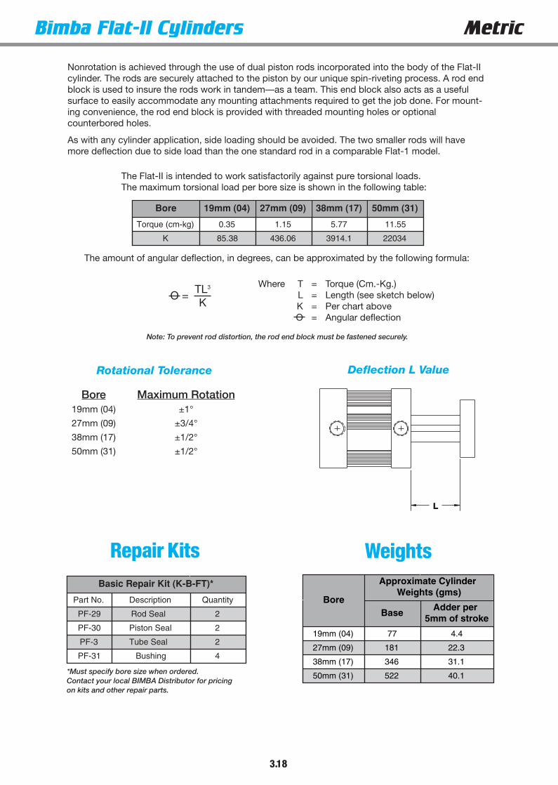
Nonrotation is achieved through the use of dual piston rods incorporated into the body of the Flat-IIcylinder. The rods are securely attached to the piston by our unique spin-riveting process. A rod endblock is used to insure the rods work in tandem—as a team. This end block also acts as a usefulsurface to easily accommodate any mounting attachments required to get the job done. For mount-ing convenience, the rod end block is provided with threaded mounting holes or optionalcounterbored holes.
As with any cylinder application, side loading should be avoided. The two smaller rods will havemore deflection due to side load than the one standard rod in a comparable Flat-1 model.
Where T = Torque (Cm.-Kg.)L = Length (see sketch below)K = Per chart aboveO = Angular deflection
O =
The Flat-II is intended to work satisfactorily against pure torsional loads.The maximum torsional load per bore size is shown in the following table:
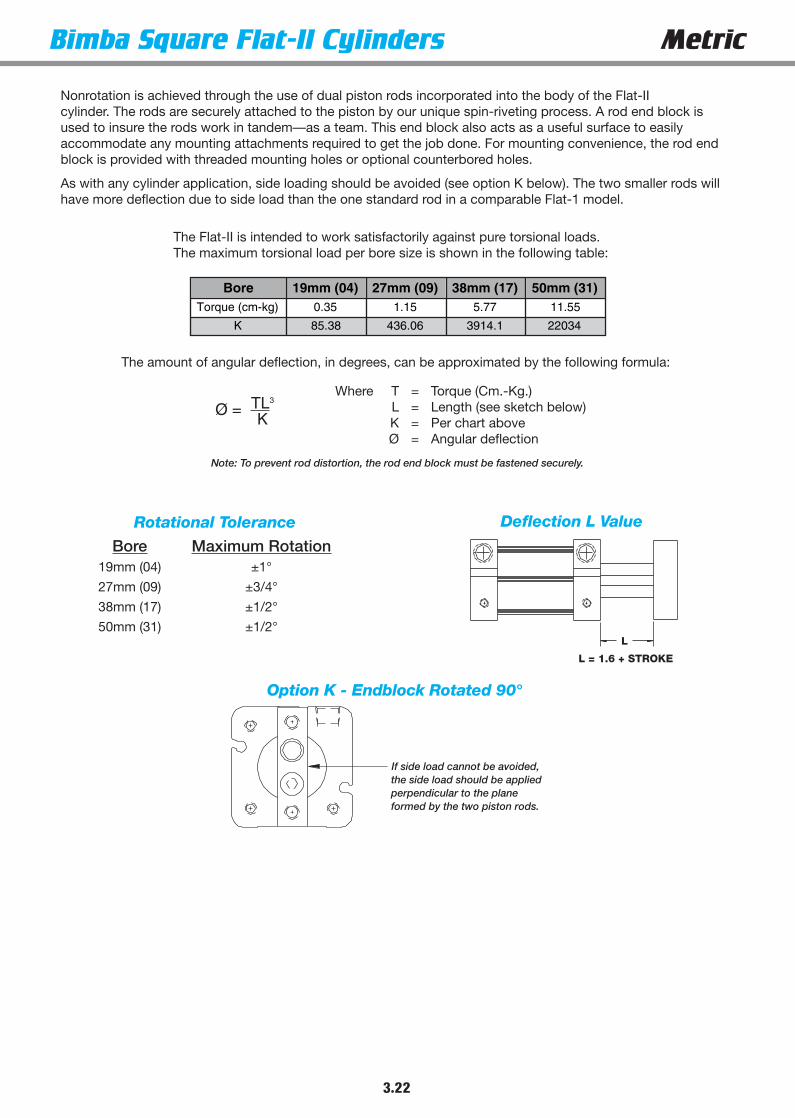
Bore 19mm (04) 27mm (09) 38mm (17) 50mm (31)
Torque (cm-kg) 0.35 1.15 5.77 11.55
K 85.38 436.06 3914.1 22034
The amount of angular deflection, in degrees, can be approximated by the following formula:
Rotational Tolerance Deflection L Value
L
Bore Maximum Rotation19mm (04) ±1°
27mm (09) ±3/4°
38mm (17) ±1/2°
50mm (31) ±1/2°
Note: To prevent rod distortion, the rod end block must be fastened securely.
WeightsRepair Kits
*Must specify bore size when ordered.Contact your local BIMBA Distributor for pricingon kits and other repair parts.
Basic Repair Kit (K-B-FT)*
Part No. Description Quantity
PF-29 Rod Seal 2
PF-30 Piston Seal 2
PF-3 Tube Seal 2
PF-31 Bushing 4
3.19
Metric Bimba Square Flat-II CylindersISO 6431
ISO 6432Flat
Pneu-TurnUltran
Flow Control
PositionSensing Solutions
CE - Counterbored EndblockG - Magnalube® GK - Endblock rotated 90 degrees (see page 3.22)L - Low Friction Seals (see page 3.21)
M, M1, M4 - Magnetic Position Sensing (see Position Sensing Solutions, page 7.7)1
Q - Low temperature operation (-40˚C to 95˚C)S - Stainless steel fasteners
T1, T4 - Additional switch track located in position #1 or 4V - High temperature seals (-18°C to 205°C)Y - Moly-coat (MoS2 I.D. coating)
EE10 - 10mm extra rod extension, etc.EE50 - 50mm extra rod extension, etc.
1 If magnetic position sensing is specified with Fluoroelastomer Seals, standardBuna-N based magnet will be provided. Magnetic position sensing is not reliableabove 50°C.
How to Order
FSTM-1740-V
TYPE STROKE LENGTHBORE SIZE
The Model Number for all Square Flat-II cylinders consists of three alphanumeric clusters. These designate type,bore size and stroke length and special options. Please refer to the charts below for an example of ModelNumber FSTM-1740-V. This is a nonrotating, double acting, 38mm bore, 40mm stroke cylinder, with hightemperature option.
FSTM - Nonrotating, Double Acting 04 - 19mm09 - 27mm17 - 38mm31 - 50mm
5 - 5mm40 - 40mm
100 - 100mmETC.
(Enter in alphabetical order, except EE which is last)
OPTIONS
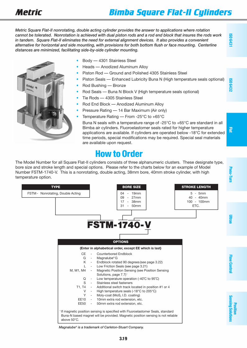
Metric Square Flat-II nonrotating, double acting cylinder provides the answer to applications where rotationcannot be tolerated. Nonrotation is achieved with dual piston rods and a rod end block that insures the rods workin tandem. Square Flat-II eliminates the need for external alignment devices. It also provides a convenientalternative for horizontal and side mounting, with provisions for both bottom flush or face mounting. Centerlinedistances are minimized, facilitating side-by-side cylinder mounting.
Magnalube® is a trademark of Carleton-Stuart Company.
• Body — 4301 Stainless Steel
• Heads — Anodized Aluminum Alloy
• Piston Rod — Ground and Polished 4305 Stainless Steel
• Piston Seals — Enhanced Lubricity Buna N (High temperature seals optional)
• Rod Bushing — Bronze
• Rod Seals — Buna N Block V (High temperature seals optional)
• Tie Rods — 4305 Stainless Steel
• Rod End Block — Anodized Aluminum Alloy
• Pressure Rating — 14 Bar Maximum (Air only)
• Temperature Rating — From -25°C to +65°C
Buna N seals with a temperature range of -25°C to +65°C are standard in allBimba air cylinders. Fluoroelastomer seals rated for higher temperatureapplications are available. If cylinders are operated below -18°C for extendedtime periods, special modifications may be required. Special seal materialsare available upon request.

3.20
Bimba Square Flat-II Cylinders Metric
C*#4 - 40 UNC - 2B x .141DPSWITCH TRACK MOUNTING
C*
C*
C*LPORT
M (TYP)
LLK
(TYP)
GJ
V
.062CA CA
B + STROKE
DD - 4 PLACES
DD* - 3 PLACES
A SQ.Ø ROD
F
THREADED2 - PLACES
E
H
Basic Model
1.6V
VH VL
EC FORSOCKET HEAD CAPSCREWS (2 - PLACES)
Bore A B C CA DD E EC F G H
19mm (04) 31.8 19 10.0 7.0 M4 x 0.7 M3 x 0.5 M3 4.8 10.7 8.4
27mm (09) 38.1 31.8 12.5 9.4 M4 x 0.7 M4 x 0.7 M4 6.4 14.9 10.7
38mm (17) 50.8 31.8 18.0 7.9 M5 x 0.8 M6 x 1.0 M6 9.5 14.6 14.3
50mm (31) 63.5 33.3 22.0 9.7 M6 x 1.0 M8 x 1.25 M8 12.7 15.7 19.1
Bore J K L LL M V VH VL
19mm (04) 10.7 4.8 M5 8.9 8.9 9.0 22.0 31.0
27mm (09) 12.7 6.4 G 1/8 10.7 8.2 9.0 27.0 37.0
38mm (17) 12.7 6.4 G 1/8 15.2 5.1 12.0 38.0 50.0
50mm (31) 15.7 6.4 G 1/8 19.3 4.7 15.0 48.0 63.0
A minimum stroke of 9.5mm is required to sense extending end-of-stroke position.See page 3.21 for length adders for magnet option.
Counterbored Rod End Block
Model FSTM(Nonrotating, doubleacting)
Standard strokes3.2mm, 5, 10, 15, 20, 25,30, 40, 50, 80, 100mm
Longer strokes availableupon request*Cand DD dimensions apply toSquare Flat-1 models with– M option in 19, 27,38, and 50mm bore sizes).
Dimensions (MM)

Options
Repair KitsBasic Repair Kit (K-B-FSTM)*
Part No. Description Quantity
PF-29-FSTM Rod Seal 2
PF-30-FSTM Piston Seal 1
PF-3-FSTM Tube Seal 2
BoreApproximate Cylinder Weights (grams)
Base Adder per 5mm
of stroke
19mm (04) 76 4.4
27mm (09) 181 22.3
38mm (17) 345 31.2
50mm (31) 467 40.0
Bore
Length Adder
Low Friction Seals (L)
Magnetic Position Sensing* (M)
Low Friction Seals and Magnetic
Position Sensing
19mm (04) 6.4 19 19
27mm (09) 9.7 12.7 12.7
38mm (17) 9.7 16 16
50mm (31) 9.7 16 16
Weights
*A minimum stroke of 9.5mm is required to sense extending end-of-stroke position.
3.21
Metric Bimba Square Flat-II CylindersISO 6431
ISO 6432Flat
Pneu-TurnUltran
Flow Control
PositionSensing Solutions
3.22
Bimba Square Flat-II Cylinders Metric
L = 1.6 + STROKE
L
Nonrotation is achieved through the use of dual piston rods incorporated into the body of the Flat-II cylinder. The rods are securely attached to the piston by our unique spin-riveting process. A rod end block isused to insure the rods work in tandem—as a team. This end block also acts as a useful surface to easilyaccommodate any mounting attachments required to get the job done. For mounting convenience, the rod endblock is provided with threaded mounting holes or optional counterbored holes.
As with any cylinder application, side loading should be avoided (see option K below). The two smaller rods willhave more deflection due to side load than the one standard rod in a comparable Flat-1 model.
Where T = Torque (Cm.-Kg.)L = Length (see sketch below)K = Per chart aboveØ = Angular deflection
The amount of angular deflection, in degrees, can be approximated by the following formula:
Rotational Tolerance Deflection L Value
Bore Maximum Rotation19mm (04) ±1°
27mm (09) ±3/4°
38mm (17) ±1/2°
50mm (31) ±1/2°
The Flat-II is intended to work satisfactorily against pure torsional loads.The maximum torsional load per bore size is shown in the following table:
Note: To prevent rod distortion, the rod end block must be fastened securely.
Ø = TL3
K
If side load cannot be avoided,the side load should be appliedperpendicular to the planeformed by the two piston rods.
Option K - Endblock Rotated 90°

3.23
Metric Bimba FM2, FM3, FM4 CylindersISO 6431
ISO 6432Flat
Pneu-TurnUltran
Flow Control
PositionSensing Solutions
Space-Saving Cylinders That Multiply Force OutputThe Bimba FM2, FM3, FM4 Series Flat-1 are double-acting, singleend rod cylinders that multiply the force output by supplying air tomultiple pistons on extension. They save space and eliminate theneed for a higher pressure system. Only one piston is powered onthe return stroke, saving air volume and operating costs.
• Body — 4301 Stainless Steel (X5 CrNi 18.9)
• Heads — Anodized Aluminum Alloy
• Piston Rod — Ground and Polished 4305 Stainless Steel (X12 CrNi18.8)
• Seals — Buna N (High temperature seals optional)
• Rod Bushing — Oil Impregnated Bronze
• Pressure Rating — 7 Bar Maximum (Air only)
• Temperature Rating — From -25°C to +65°C
Buna N seals with a temperature range of -25°C to +65°C arestandard in all Bimba air cylinders. Fluoroelastomer seals rated forhigher temperature applications are available. If cylinders are oper-ated below -18°C for extended time periods, special modificationsmay be required. Special seal materials are available upon request.
How it Works
AirExhaust
AirDrawn In
AirDrawn In
AirDrawn In
AirInlet
Retraction – air supplied to one piston only
Extension – air supplied to multiple pistons
AirInlet
AirExhaust
AirExhaust
AirExhaust
AirExhaust
Retraction-air supplied to one piston only
Extension-air supplied to multiple pistons

3.24
Bimba FM2, FM3, FM4 Cylinders Metric
The model number for all FM2 Series Flat-1 cylinders consists of three alphanumeric clusters. These designate type,bore size and stroke length, and mounting and special options. Please refer to the charts below for our example ofModel Number FM2-5025-3M. This is a 63mm bore FM2 Series Flat-1 with 25mm stroke, threaded mounting holesin both ends, with the magnetic position sensing option.
How to Order
FM2-5025-3 M
TYPE STROKE LENGTH
5 - 5mm40 - 40mm
100 - 100mmETC.
BORE SIZE
50 - 63mm70 - 76mm125 - 101mm
FM2 - Two stage extend, single stage retractFM3 - Three stage extend, single stage retractFM4 - Four stage extend, single stage retract
MOUNTING OPTIONS OPTIONS
(Enter in numeric order) (Enter in alphabetical order, except EE which is last)
3 - Threaded mounting holes,both ends
3F - Threaded mounting holes, front3R - Threaded mounting holes, rear
4 - Screw clearance holes, both ends4F - Screw clearance holes, front4R - Screw clearance holes, rear
Multiply the air line pressure by the power factor to get the approximateforce. For example, an FM2-5025-3 operated at 6 bars will exert a forceof 3636 N. on extension, and 1704 N. on retraction.
FTF - Fine female thread (see page 3.27)G - Magnalube® GL - Low friction seals (see page 3.25)
M, M1, M3, M4 - Magnetic position sensing (see Position Sensing Solutions, page 7.7)1
MTF - Male rod end (fine thread) (see page 3.25)MT - Male rod end (coarse thread)
(see page 3.25)NT - Non-threaded rod
P2, P3, P4 - Front port position #2, etc. (see page 3.26)P6, P7, P8 - Rear port position #6, etc. (see page 3.26)
Q - Low temperature operation (-40˚C to 95˚C)T1, T3, T4 - Additional switch mounting post located
in position #1, 3 or 4V - High temperature seals (-18° to +205° C)
W - Rod wiper (Buna N only) (see page 3.25)Y - Moly-coat (MoS2 I.D. coating)
EE10 - 10mm extra rod extension, etc.EE50 - 50mm extra rod extension, etc.
1 If magnetic position sensing is specified with Fluoroelastomer Seals, standard Buna-N based magnet will be provided. Magneticposition sensing is not reliable above 50°C.
Magnalube® is a trademark of Carleton-Stuart Company.

3.25
Metric Bimba FM2, FM3, FM4 CylindersISO 6431
ISO 6432Flat
Pneu-TurnUltran
Flow Control
PositionSensing Solutions
(Dimensional variations from standard as shown)
Options(mm)
*A minimum stroke of 9.5mm is required to sense extending end-of-stroke position.
Rod Wiper (Option W)(Buna N standard, not available in Viton)
Male Rod Ends (Option MT or MTF)
Bore WD
63mm (50) 28.6
76mm (70) 31.8
101mm (125) 34.9
Bore MT MTF LG
63mm (50) M12 M12 x 1.25 16
76mm (70) M16 M16 x 1.5 20
101mm (125) M20 M20 x 1.5 20
ETHREAD
LG4.8
9.5
WD
Bore Type
Length Adder
Low Friction Seal (L)
Magnetic Position Sensing* (M)
Low Friction Seal & Magnetic Position
Sensing (LM)
63mm (50)
FM2 19.0
22.2
31.8
FM3 28.7 41.4
FM4 38.1 50.8
76mm (70)
FM2 25.4
22.2
35.1
FM3 38.1 47.8
FM4 50.8 60.5
101mm (125)
FM2 25.4
22.2
35.1
FM3 38.1 47.8
FM4 50.8 60.5

3.26
Bimba FM2, FM3, FM4 Cylinders Metric
B + (3 x STROKE)*
PORT
VENTST
J (TYP)
3.2
PORTL PORT
FROD DIA.
C BOLTCIRCLE
2
1 3
4
E(4) CLEARHOLES FOR DSOCKET HEADCAP SCREW
H
A
KV
6
7 5
8
Z DIA. ADDITIONAL MOUNTINGHOLES FOR FM3 & FM4 76mm &101mm BORES ONLY
B + (4 x STROKE)*
PORT
VENTST
J (TYP)
3.2
PORTL PORT
FROD DIA.
C BOLTCIRCLE
2
1 3
4
E(4) CLEARHOLES FOR DSOCKET HEADCAP SCREW
H
A
KV
6
7 5
8
Z DIA. ADDITIONAL MOUNTINGHOLES FOR FM3 & FM4 76mm &101mm BORES ONLY
B + (2 x STROKE)*
PORT
VENTT
J (TYP)
3.2
PORTL PORT
FROD DIA.
C BOLTCIRCLE
2
1 3
4
E(4) CLEARHOLES FOR DSOCKET HEADCAP SCREW
H
A
KV
6
7 5
8
Basic Model Standard strokes3.2mm, 5mm, 10mm, 15mm, 20mm, 25mm, 30mm, 40mm, 50mm, 80mm, 100mmSpecial strokes available on request
Model FM2
Model FM3
Model FM4

3.27
Metric Bimba FM2, FM3, FM4 CylindersISO 6431
ISO 6432Flat
Pneu-TurnUltran
Flow Control
PositionSensing Solutions
Mounting OptionsThreaded Mounting Holes(available either or both ends)(-3R shown)
Dimensions(mm)
Bore AB**
C D E Std. E Fine E DepthFM2 FM3 FM4
63mm (50) 95.0 58.2 80.0 102.1 83.0 M6 M12 M12 x 1.25 17.8
76mm (70) 107.7 60.7 83.3 106.2 96.0 M6 M16 M16 x 1.5 18.5
101mm (125) 139.5 77.2 105.4 133.9 125 M8 M20 M20 x 1.5 20.3
Bore F H J K L R T V X Z
63mm (50) 19.1 16.0 16.7 8.3 R 1/8 M6 23.0 14.7 10.5 N/A
76mm (70) 22.2 19.0 17.5 8.3 R 1/8 M6 23.8 14.7 10.5 7.1
101mm (125) 25.4 22.0 21.4 10.7 R 1/4 M8 31.0 19.1 13.5 8.6
Screw Clearance Holes(available either or both ends)(-4R shown)
X
Bore Type
"B"
Stroke
3.175 6.350
63mm (50)
FM2 67.3 70.4
FM3 92.5 98.3
FM4 117.6 126.2
76mm (70)
FM2 69.9 73.2
FM3 95.8 101.9
FM4 121.7 130.8
101mm (125)
FM2 85.9 89.7
FM3 117.1 124.2
FM4 148.6 158.5
**For Strokes 3.2 and .5
*See page 3.25 for length adders for options.

3.28
Bimba FM2, FM3, FM4 Cylinders Metric
Repair Kits
Weights
Basic Repair Kit (K-B-FM__)*
Part No. Description Quantity**
PF-1 Rod Seal 2, 3 or 4
PF-2 Piston Seal 2, 3 or 4
PF-3 Tube Seal 3, 4 or 5
PF-4 Bushing 3, 4 or 5
Wiper Option Repair Kit (K-B-FM__-W)*
Part No. Description Quantity**
PF-1 Rod Seal 2, 3 or 4
PF-2 Piston Seal 2, 3 or 4
PF-3 Tube Seal 3, 4 or 5
PF-4 Bushing 3, 4 or 5
PF-5 Wiper Bushing 1
PF-6 Wiper 1
Bore
Approximate Cylinder Weights (gms)
Base Adder per 5mm of stroke
FM2 FM3 FM4 FM2 FM3 FM4
63mm (50) 1055 1511 1967 53.5 80.2 71.4
76mm (70) 1415 2013 2611 71.4 107.0 142.7
101mm (125) 2640 3793 4947 89.1 133.7 178.3
*Must specify model and bore size when ordered.**Quantities listed correspond with FM2, FM3 or FM4.
3.29
Metric Bimba FMP CylindersISO 6431
ISO 6432Flat
Pneu-TurnUltran
Flow Control
PositionSensing Solutions
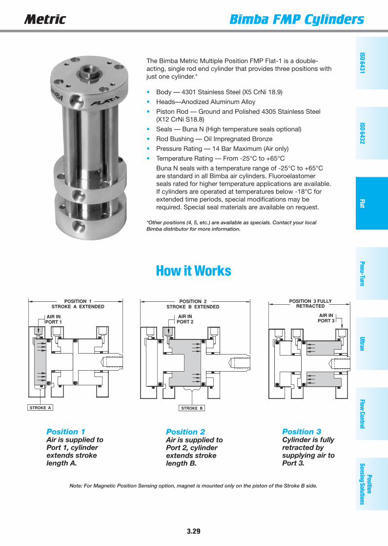
The Bimba Metric Multiple Position FMP Flat-1 is a double-acting, single rod end cylinder that provides three positions withjust one cylinder.*
• Body — 4301 Stainless Steel (X5 CrNi 18.9)
• Heads—Anodized Aluminum Alloy
• Piston Rod — Ground and Polished 4305 Stainless Steel(X12 CrNi S18.8)
• Seals — Buna N (High temperature seals optional)
• Rod Bushing — Oil Impregnated Bronze
• Pressure Rating — 14 Bar Maximum (Air only)
• Temperature Rating — From -25°C to +65°C
Buna N seals with a temperature range of -25°C to +65°Care standard in all Bimba air cylinders. Fluoroelastomerseals rated for higher temperature applications are available.If cylinders are operated at temperatures below -18°C forextended time periods, special modifications may berequired. Special seal materials are available on request.
*Other positions (4, 5, etc.) are available as specials. Contact your localBimba distributor for more information.
POSITION 1STROKE A EXTENDED
AIR INPORT 1
STROKE A
POSITION 3 FULLYRETRACTED
AIR INPORT 3
POSITION 2STROKE B EXTENDED
AIR INPORT 2
STROKE B
How it Works
Position 1Air is supplied toPort 1, cylinderextends strokelength A.
Position 3Cylinder is fullyretracted bysupplying air toPort 3.
Position 2Air is supplied toPort 2, cylinderextends strokelength B.
Note: For Magnetic Position Sensing option, magnet is mounted only on the piston of the Stroke B side.

3.30
Bimba FMP Cylinders Metric
The model number for all Metric Multiple Position FMP Flat-1 cylinders consists of three alphanumeric clusters.The first cluster designates type, the second cluster bore size and stroke lengths A and B, and the third clusterdesignates mounting and special options. Please refer to the charts below for an example of Model NumberFMP-1750/25-1V. This is a 38mm bore multiple position FMP Flat-1 with a 50mm stroke for position A, plus anadditional stroke of 25mm for position B, with a pivot mount on the rear head and high temperature option.
How to Order
FMP-1750/25-1V
MOUNTING OPTIONS
TYPE BORE SIZE
02 - 14mm 31 - 50mm04 - 19mm 50 - 63mm09 - 27mm 70 - 76mm17 - 38mm 125 - 101mm
25 - 25mm50 - 50mm75 - 75mm
ETC.
STROKE LENGTH
FMP -Double acting multiple position,
single end rod
STROKE LENGTH
25 - 25mm50 - 50mm75 - 75mm
ETC.
OPTIONS
(Enter in alphabetical order, except EE which is last)(Enter in numeric order)
No Number - Basic model1 - Pivot mount
1N - Pivot mount 90° from standard3 - Threaded mounting holes, both ends
3F - Threaded mounting holes, front3R - Threaded mounting holes, rear
4 - Screw clearance holes, both ends4F - Screw clearance holes, front4R - Screw clearance holes, rear
FTF - Fine female rod thread (see page 3.33)G - Magnalube® GL - Low friction seals (see table page 3.31)
M, M1, M3, M4 - Magnetic position sensing (see Position Sensing Solutions, page 7.7)1
MT - Male rod thread end (coarse thread) (see page 3.31)MTF - Male rod thread end (fine thread) (see page 3.31)
NT - Non-threaded rodP2*, P3, P4* - Front port position #2, etc. (see page 3.32)P6*, P7, P8* - Rear port position #6, etc. (see page 3.32)
Q - Low temperature operation (-40˚C to 95˚C)T1, T3, T4 - Additional switch mounting post
located in position #1, 3 or 4V - High temperature seals (-18 to +205°C)
W - Rod wiper (Buna-N only) (see page 3.31)Y - Moly-coat (MoS2 I.D. coating)
EE10 - 10mm extra rod extension, etc.EE50 - 50mm extra rod extension, etc.
*Not available in 14mm bore1If magnetic position sensing is specified with Fluoroelastomer Seals, standard Buna-N based magnet will be provided. Magnetic position sensing is not reliable above 50°C.
Magnalube® is a trademark of Carleton-Stuart Company.

3.31
Metric Bimba FMP CylindersISO 6431
ISO 6432Flat
Pneu-TurnUltran
Flow Control
PositionSensing Solutions
Options(mm)(Dimensional variations from standard as shown.)
*A minimum stroke of 9.5mm is required to sense extending end-of-stroke position.
Length Adder
BoreLow Friction
Seals (L)Magnetic Position
Sensing* (M)Low Friction Seals and Magnetic
Position Sensing
14mm (02), 19mm (04) 12.7 22.2 28.6
27mm (09), 38mm (17), 50mm (31), 63mm (50) 19.1 22.2 31.8
76mm (70), 101mm (125) 25.4 22.2 34.9
ETHREAD
LG
BoreE
LGMT MTF
14mm (02) M4 M4 x 0.5 10
19mm (04) M5 M5 x 0.5 10
27mm (09) M8 M8 x 1.0 12
38mm (17) M10 M10 x 1.25 12
50mm (31) 63mm (50) M12 M12 x 1.25 16
76mm (70) M16 M16 x 1.5 20
101mm (125) M20 M20 x 1.5 20
Male Rod Ends (Option MT or MTF)
4.8
9.5
WD
Rod Wiper (Option W)(Buna N standard, not available in Viton)
Bore WD
14mm (02) 14.3
19mm (04) 17.5
27mm (09) 22.2
38mm (17) 25.4
50mm (31) 63mm (50) 28.6
76mm (70) 31.8
101mm (125) 34.9
14mm 19mm 27mm 38mm 50mm 63mm 76mm 101mm
BASE MODEL STROKE A 4.8 4.8 6.4 6.4 6.4 9.5 9.5 8.7
Minimum Stroke
No minimum for stroke B. No minimum for stroke A or B with low friction seal option.
BoreModel

3.32
Bimba FMP Cylinders Metric
Basic Model
Threaded Mounting Holes(available either or both ends)(-3R shown)14mm Bore
Pivot Mount(-1 shown) Complete with bronzepivot bushing. (Not available as anaccessory)
Screw Clearance Holes(available either or both ends)(-4R shown) Screw clearance holesstandard on all center sections
Mounting Options
19mm Bore and larger
X
THREADED2R HOLES
BOLT CIRCLECLOCATION OF MTG. HOLES14mm BORE ONLY
TYP.90º
*43° - 19mm BORE ONLY 90°TYP
4 THREADEDR HOLES
C BOLTCIRCLE
*
45° - ALL OTHER BORES

3.33
Metric Bimba FMP CylindersISO 6431
ISO 6432Flat
Pneu-TurnUltran
Flow Control
PositionSensing Solutions
Dimensions(mm)
BoreE
DEPTHF G H J JJ K L
14mm (02) 11.7 6.3 8.7 5.5 11.9 6.8 3.6 M5
19mm (04) 11.7 7.9 8.7 6.0 11.9 6.8 3.6 M5
27mm (09) 17.8 12.7 12.7 11.0 17.5 11.1 6.4 G 1/8
38mm (17) 17.8 15.9 12.7 12.0 17.5 11.1 6.4 G 1/8
50mm (31) 17.8 19.1 13.5 16.0 18.3 11.1 6.4 G 1/8
63mm (50) 17.8 19.1 16.7 16.0 23.0 14.7 8.3 G 1/8
76mm (70) 18.5 22.2 17.5 19.0 23.8 14.7 8.3 G 1/8
101mm (125) 20.3 25.4 21.4 22.0 31.0 20.2 10.7 G 1/4
Bore Q R S T U W X Y Z
14mm (02) 5 M3 9.5 5 6.5 19 6 16 5
19mm (04) 5 M3 9.5 5 6.5 19 6 19 5
27mm (09) 5 M3 9.5 6.5 6.5 20.5 6 19 5
38mm (17) 10 M5 19 6.5 11.5 30 9 35 9.5
50mm (31) 10 M5 19 8 11 32 9 35 9.5
63mm (50) 10 M6 19 9.5 11 33.5 10.5 35 9.5
76mm (70) 16 M6 25.5 9.5 14 43 10.5 47.5 9.5
101mm (125) 16 M8 25.5 11 14.5 44.5 13.5 47.5 9.5
*See page 3.31 for length adders for options.
Bore Aa Ba* C DD DE E
(Std) (Fine)
14mm (02) 28.5 29.0 22.5 2 M3 M4 M4 x 0.5
19mm (04) 38.0 29.0 31.0 4 M3 M5 M5 x 0.5
27mm (09) 50.6 42.5 43.0 4 M3 M8 M8 x 1.0
38mm (17) 66.4 43.3 56.0 4 M5 M10 M10 x 1.25
50mm (31) 79.1 45.6 68.0 4 M5 M12 M12 x 1.25
63mm (50) 95.0 57.2 83.0 4 M6 M12 M12 x 1.25
76mm (70) 107.7 59.5 96.0 4 M6 M16 M16 x 1.5
101mm (125) 139.5 76.2 125.0 4 M8 M20 M20 x 1.5

3.34
Bimba FMP Cylinders Metric
Repair Kits
Basic Repair Kit (K-B FOP)*
Part No. Description Quantity
PF-1 Rod Seal 2
PF-2 Piston Seal 2
PF-3 Tube Seal 3
PF-4 Bushing 3
Wiper Option Repair Kit (K-B-FOP-W)*
Part No. Description Quantity
PF-1 Rod Seal 2
PF-2 Piston Seal 2
PF-3 Tube Seal 3
PF-4 Bushing 2
PF-5 Wiper Bushing 1
PF-6 Wiper 1
Weights
Bore
Approximate Cylinder Weights (gms)
BaseAdder per
5mm of stroke
14mm (02) 94 7.1
19mm (04) 128 9
27mm (09) 281 26.7
38mm (17) 530 35.5
50mm (31) 695 44.6
63mm (50) 1170 53.4
76mm (70) 1500 71.4
101mm (125) 2912 89.1
*Must specify bore size when ordered. Contact your localBimba distributor for pricing on kits and other repair parts.

3.35
Metric Bimba Flat-1 CylindersISO 6431
ISO 6432Flat
Pneu-TurnUltran
Flow Control
PositionSensing Solutions
Accessories(mm)(All Models)
Model Bore LD MT Q S SH SD TH TL
BCM-114mm (02) 19mm (04) 27mm (09)
14.5 19 5 10 3 25.5 4 20
BCM-238mm (17) 50mm (31) 63mm (50)
24 35 10 19.5 4 44.5 5.5 34
BCM-3 76mm (70) 101mm (125) 32 50 16 26 6 63.5 6.5 46
Clevis BracketAnodized aluminum alloy, complete with chrome plated steel pin
Bracket intended to mount with either rod pivot or pivot mount, not directly to thecylinder rear head.
Trunnion Bracket (pair)Anodized aluminum alloy, complete with bronze pivot bushings
Model Bore BA BT HT LT M N NA NB
BTM-1 19mm (04) 14.5 4 15.5 28.5 8 3 8 5.5
BTM-227mm (09) 38mm (17) 50mm (31)
20.5 6 22 38 12.5 6 10 8
BTM-3 63mm (50) 76mm (70) 24 8 25 41.5 16 8 12 9.5
BTM-4 101mm (125) 27 10 31.5 47.5 19 10 14 11
Model Bore E LN MS NT Q S
RPM-1/2 14mm (02) M4 9.5 11.5 6.5 5 9.5
RPM-1 19mm (04) M5 9.5 11.5 6.5 5 9.5
RPM-2 27mm (09) M8 16 11.5 6.5 5 9.5
RPM-3 38mm (17) M10 16 18.5 11 10 19
RPM-4 50mm (31) 63mm (50) M12 19 18.5 11 10 19
RPM-5 76mm (70) M16 22.5 25.5 16 16 25.5
RPM-6 101mm (125) M20 22.5 25.5 16 16 25.5
Rod PivotZinc plated, high strength, heat treated alloy steel,complete with a bronze pivot bushing and nut
TLQ PIN DIA.
SDSQUARE
MTSQUARE
S
SHBOLTHOLE DIA.
THLD
Selection Guide
Accessory Flat-1Square Flat-1
Square Flat-II
Flat-II FM2 Series
FMP
Clevis Bracket X X X X N/A X
Trunnion Bracket X N/A N/A X N/A N/A
Rod Pivot X X N/A N/A X X
ETHREAD
NT
S
Q DIA. FORPIVOT PIN
MS
LN
S

3.36
Bimba Flat-1 Cylinders Metric