440 ph meter instruction manual - cole-parmer · 2016-11-15 · meter with a shorting (test) clip...
TRANSCRIPT
1109118-1 Rev. A,10/96
Instruction ManualThis manual contains complete instructions for setting up and using
the 440 pH meter. Applications information is also available.
The information contained in this manual was correct at the time of
going to print. However, we continue to improve products and reserve
the right to change specifications, equipment and maintenance
procedures at any time.
This manual is copyrighted, and all rights are reserved. No part of
this manual may be reproduced by any means or in any form without
prior consent in writing.
The power supply unit is classed as IEC Class II equipment
(equipment providing an adequate degree of protection against
electric shocks, in which additional safety precautions, for example,
double or reinforced insulation, are included). The 440 is intended for
use by persons knowledgeable in safe laboratory practices. If the 440
is not used in accordance with these instructions for use, the
protection provided by the equipment may be impaired.
The 440 is suitable for direct current only.
This equipment generates, uses and can radiate radio frequency
energy and if not installed and used in accordance with the
instruction manual, may cause interference with radio
communications. It has been tested and found to comply with the
limits for a Class A computing device pursuant to Subpart J of
Part 15 of FCC Rules, which are designed to provide reasonable
protection against such interference when operated in a commercial
environment. Operation of this equipment in a residential area is
likely to cause interference in which case the user at his own expense
will be required to take whatever measures may be required to
correct the interference.
There are no user replaceable parts in the 440 or power supply unit.
Do not remove the covers.
440 pH Meter
2 109118-1 Rev. A, 10/96
Contents
1 Set Up
1.1 Unpacking and Installation ................................................ 3
1.2 Input and Output Connections ........................................... 4
1.3 Display and Controls ......................................................... 4
2 Operation
2.1 Calibrating a pH Electrode ............................................... 7
2.2 Measuring Samples ........................................................... 8
2.3 Automatic Endpoint (Auto Read) ....................................... 8
2.4 Changing the Calibration Buffer Settings .......................... 8
2.5 mV Measurements ............................................................ 9
2.6 Temperature Measurements ........................................... 10
2.7 Changing the Resolution ................................................. 11
2.8 Chart Recorder ................................................................ 11
2.9 Interfacing via the RS232 Output .................................... 12
3 Support Information
3.1 Basic Theory .................................................................... 13
3.2 Operating Hints ................................................................ 14
3.3 Maintenance .................................................................... 153.3.1 Meter Maintenance .......................................................... 153.3.2 Electrode Maintenance .................................................... 15
3.4 Problem Solving .............................................................. 163.4.1 Meter Test and Reset ...................................................... 163.4.2 Meter Error Codes ........................................................... 173.4.3 Electrode Problem Solving .............................................. 18
3.5 Meter Specifications ........................................................ 20
Consumables and Accessories ............................... inside rear cover
Warranty .................................................................. inside rear cover
3109118-1 Rev. A,10/96
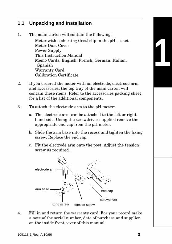
11.1 Unpacking and Installation
1. The main carton will contain the following:
Meter with a shorting (test) clip in the pH socket
Meter Dust Cover
Power Supply
This Instruction Manual
Memo Cards, English, French, German, Italian,
Spanish
Warranty Card
Calibration Certificate
2. If you ordered the meter with an electrode, electrode arm
and accessories, the top tray of the main carton will
contain these items. Refer to the accessories packing sheet
for a list of the additional components.
3. To attach the electrode arm to the pH meter:
a. The electrode arm can be attached to the left or right-
hand side. Using the screwdriver supplied remove the
appropriate end cap from the pH meter.
b. Slide the arm base into the recess and tighten the fixing
screw. Replace the end cap.
c. Fit the electrode arm onto the post. Adjust the tension
screw as required.
4. Fill in and return the warranty card. For your record make
a note of the serial number, date of purchase and supplier
on the inside front cover of this manual.
electrode arm
arm base
fixing screw
end cap
screwdriver
tension screw
4 109118-1 Rev. A, 10/96
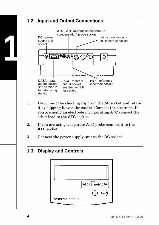
11.2 Input and Output Connections
1. Disconnect the shorting clip from the pH socket and retain
it by clipping it over the socket. Connect the electrode. If
you are using an electrode incorporating ATC connect the
other lead to the ATC socket.
2. If you are using a separate ATC probe connect it to the
ATC socket.
3. Connect the power supply unit to the DC socket.
1.3 Display and Controls
DC - powersupply unitsocket
ATC - ATC (automatic temperaturecompensation) probe socket
pH - combination orpH electrode socket
DATA - dataoutput socket,see Section 2.9for interfacingdetails
REC - recorderoutput socket,see Section 2.8for details
REF - referenceelectrode socket

5109118-1 Rev. A,10/96
1.3 Display and Controls (cont)
Selects pH or mV mode.
Increases displayed value; used when settingcalibration buffers. Also changes display resolution.
Decreases displayed value; used when settingcalibration buffers. Also changes display resolution.
Selects calibration buffers.
Selects automatic endpoint detection.
Turns the display off, and places the meter in standbymode. Wakes meter up.
Starts a calibration sequence in pH mode.
Starts sample measurement in both modes. Press againto freeze display in manual endpoint mode.
<mode
<
buffer
on/off
autoread
cal
read
1

6 109118-1 Rev. A, 10/96
11.3 Display and Controls (cont)
440 Display
temperature orslope value
automatic or manualtemperature compensation
slope valuedisplayed
calibration bufferindicator
auto endpointis selected
main display
mode
error code
Example pH Reading
7109118-1 Rev. A,10/96
2
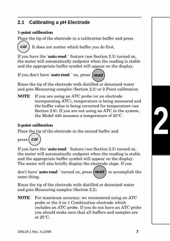
2.1 Calibrating a pH Electrode
1-point calibrationPlace the tip of the electrode in a calibration buffer and press
It does not matter which buffer you do first.
If you have the 'auto read ' feature (see Section 2.3) turned on,
the meter will automatically endpoint when the reading is stable
and the appropriate buffer symbol will appear on the display.
If you don't have 'auto read ' on, press
Rinse the tip of the electrode with distilled or deionized water
and goto Measuring samples (Section 2.2) or 2-Point calibration.
NOTE If you are using an ATC probe (or an electrode
incorporating ATC), temperature is being measured and
the buffer value is being corrected for temperature (see
Section 2.6). If you are not using an ATC in the system,
the Model 440 assumes a temperature of 25°C .
2-point calibrationPlace the tip of the electrode in the second buffer and
press
If you have the 'auto read ' feature (see Section 2.3) turned on,
the meter will automatically endpoint when the reading is stable
and the appropriate buffer symbol will appear on the display.
The meter will also briefly display the electrode slope. If you
don't have 'auto read ' turned on, press to accomplish the
same thing.
Rinse the tip of the electrode with distilled or deionized water
and goto Measuring samples (Section 2.2).
NOTE For maximum accuracy, we recommend using an ATC
probe or the 3-in-1 Combination electrode which
includes an ATC probe. If you do not have an ATC probe
you should make sure that all buffers and samples are
at 25°C.
cal
cal
read
read
8 109118-1 Rev. A, 10/96
2
2.2 Measuring Samples
NOTE Good laboratory practice dictates that electrodes should
be calibrated at least daily.
Place the tip of the electrode in the sample and press to
start the measurement. The decimal point will be
flashing whenever the electrode is reading.
If you are using the 'auto read ' function the display freezes
when a stable endpoint is reached (see Section 2.3). To manually
freeze the display when the reading is stable, press
2.3 Automatic Endpoint (Auto Read)
The 'auto read ' function checks the electrode output for stability
and automatically freezes the display when the reading appears
stable. It can be used during calibration and routine
measurements.
Turn auto endpoint on by pressing
The auto endpoint indicator will appear at the top right of
the meter display. While the meter is reading, both the 'A' and
the decimal will flash. When the endpoint is reached, both will
stop flashing.
To start another reading press
To cancel auto endpoint press again.
2.4 Changing the Calibration Buffer Settings
The default settings in the meter are for 4.00, 7.00 and 10.01
buffers. The Model 440 will allow you to change these settings to
any buffer values that you wish to work with.
autoread
read
read
autoread
read
9109118-1 Rev. A,10/96
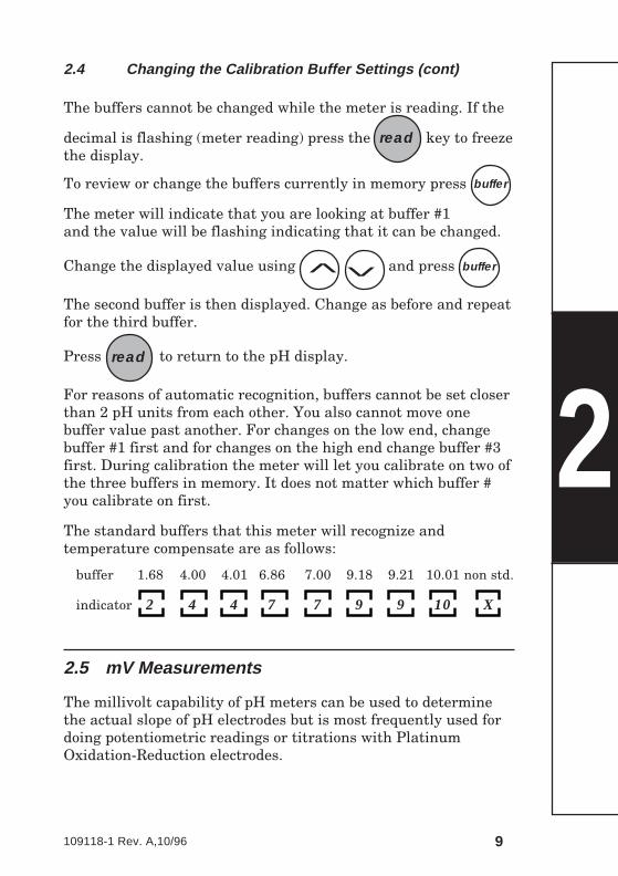
2.4 Changing the Calibration Buffer Settings (cont)
The buffers cannot be changed while the meter is reading. If the
decimal is flashing (meter reading) press the key to freeze
the display.
To review or change the buffers currently in memory press
The meter will indicate that you are looking at buffer #1
and the value will be flashing indicating that it can be changed.
Change the displayed value using and press
The second buffer is then displayed. Change as before and repeat
for the third buffer.
Press to return to the pH display.
For reasons of automatic recognition, buffers cannot be set closer
than 2 pH units from each other. You also cannot move one
buffer value past another. For changes on the low end, change
buffer #1 first and for changes on the high end change buffer #3
first. During calibration the meter will let you calibrate on two of
the three buffers in memory. It does not matter which buffer #
you calibrate on first.
The standard buffers that this meter will recognize and
temperature compensate are as follows:
buffer 1.68 4.00 4.01 6.86 7.00 9.18 9.21 10.01 non std.
indicator 2 4 4 7 7 9 9 10 X
2.5 mV Measurements
The millivolt capability of pH meters can be used to determine
the actual slope of pH electrodes but is most frequently used for
doing potentiometric readings or titrations with Platinum
Oxidation-Reduction electrodes.
2read
<<
buffer
read
buffer
10 109118-1 Rev. A, 10/96
2
2.5 mV Measurements (cont)
Press until mV shows at the top of the display.
Put the tip of the electrode in the sample and press The
meter will display absolute millivolts.
When the reading is stable, press to freeze the display.
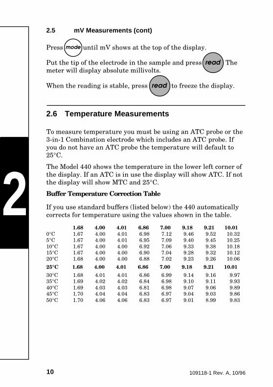
2.6 Temperature Measurements
To measure temperature you must be using an ATC probe or the
3-in-1 Combination electrode which includes an ATC probe. If
you do not have an ATC probe the temperature will default to
25°C.
The Model 440 shows the temperature in the lower left corner of
the display. If an ATC is in use the display will show ATC. If not
the display will show MTC and 25°C.
Buffer Temperature Correction Table
If you use standard buffers (listed below) the 440 automatically
corrects for temperature using the values shown in the table.
1.68 4.00 4.01 6.86 7.00 9.18 9.21 10.010°C 1.67 4.00 4.01 6.98 7.12 9.46 9.52 10.32
5°C 1.67 4.00 4.01 6.95 7.09 9.40 9.45 10.25
10°C 1.67 4.00 4.00 6.92 7.06 9.33 9.38 10.18
15°C 1.67 4.00 4.00 6.90 7.04 9.28 9.32 10.12
20°C 1.68 4.00 4.00 6.88 7.02 9.23 9.26 10.06
25°C 1.68 4.00 4.01 6.86 7.00 9.18 9.21 10.01
30°C 1.68 4.01 4.01 6.86 6.99 9.14 9.16 9.97
35°C 1.69 4.02 4.02 6.84 6.98 9.10 9.11 9.93
40°C 1.69 4.03 4.03 6.81 6.98 9.07 9.06 9.89
45°C 1.70 4.04 4.04 6.83 6.97 9.04 9.03 9.86
50°C 1.70 4.06 4.06 6.83 6.97 9.01 8.99 9.83
mode
read
read
11109118-1 Rev. A,10/96
2
2.7 Changing the Resolution
The resolution in pH can be changed between one and two
decimal places. Start by pressing to freeze the display.
Use the to change resolution from 0.0 to 0.00
Use the to change resolution from 0.00 to 0.0
Press to resume normal operation.
2.8 Chart Recorder
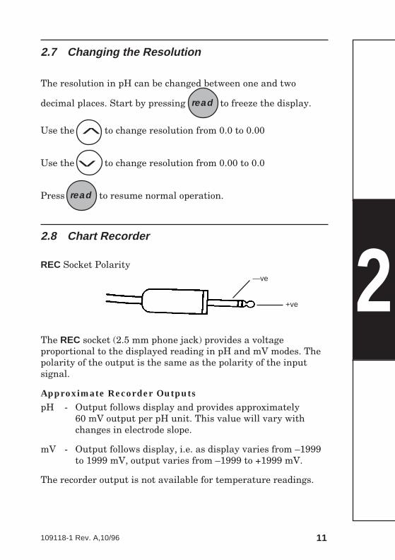
REC Socket Polarity
The REC socket (2.5 mm phone jack) provides a voltage
proportional to the displayed reading in pH and mV modes. The
polarity of the output is the same as the polarity of the input
signal.
Approximate Recorder OutputspH - Output follows display and provides approximately
60 mV output per pH unit. This value will vary with
changes in electrode slope.
mV - Output follows display, i.e. as display varies from –1999
to 1999 mV, output varies from –1999 to +1999 mV.
The recorder output is not available for temperature readings.
<
<read
read
—ve
+ve
12 109118-1 Rev. A, 10/96
2
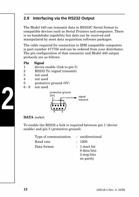
2.9 Interfacing via the RS232 Output
The Model 440 can transmit data in RS232C Serial format to
compatible devices such as Serial Printers and computers. There
is no handshake capability but data can be received and
manipulated by most data acquisition software packages.
The cable required for connection to IBM compatible computers
is part number 477758 and can be ordered from your distributor.
The pin configuration of that connector and Model 440 output
protocols are as follows:
Pin Signal1 device enable (link to pin 5)
2 RS232 Tx (signal transmit)
3 not used
4 not used
5 protective ground (0V)
6 - 9 not used
DATA socket
To enable the RS232 a link is required between pin 1 (device
enable) and pin 5 (protective ground).
Type of communication - unidirectional
Baud rate - 1200
Data format - 1 start bit
8 data bits
2 stop bits
no parity
protective ground(0V) signal
transmit5 1
69
13109118-1 Rev. A,10/96
3.1 Basic Theory
pH is the unit of measurement of the acidity or alkalinity of a
solution, and is expressed as the negative logarithm of the
hydrogen ion concentration:
pH = –log[H+]
pH 0 is very acidic, pH 14 is very alkaline and pH 7 is neutral.
For routine pH measurements a sensing electrode and a
reference electrode or a combination electrode (both electrodes in
one body) are used along with a meter capable of displaying the
measurements.
The pH sensing electrode has an internal solution with a constant
pH value, and develops a potential when placed in a solution. This
is caused by the activity of the H+ ions in the solution. The reference
electrode has a defined, stable potential irrespective of the H+
activity in the sample. The Model 440 measures and converts the
resulting minute electrode voltages into a pH reading.
The response of a pH electrode (or its slope) is defined by the
Nernst equation:
Electrode response = E0 – 2.3RT . pH
nF
where: E0 = a constant factor T = the temperature (Kelvin)
R = the gas constant n = the ionic charge
F = the Faraday constant
The theoretical slope for an electrode is 59.16 mV where the H+
ionic charge (n) = 1 at 25°C (298K). This means that for a one
unit change in pH the system will sense a change of 59.16 mV.
The measurement of electrode slope is a good indication of
electrode condition.
Temperature is also an important consideration when measuring
pH. It affects the electrode slope. ATC probes are recommended
so that the slope can be corrected for temperature. There are
many other factors that affect pH.
Further information on pH theory and the factors that affect the
ability to do accurate pH readings is included in ‘Guide to pH
Measurement’.
3
14 109118-1 Rev. A, 10/96
3.2 Operating Hints
This section gives some brief operating hints and good laboratory
practices to help assure trouble free pH measurements.
1. New electrodes (or electrodes that have been in storage)
should be conditioned in one inch (25 mm) of pH 7.0 or 4.0
buffer for several hours prior to their use. Make sure that the
wetting cap has been removed from the tip of the electrode.
2. Always remove the wetting cap and fill hole plug during
calibration and measurements. Replace the fill hole plug
when done.
3. Calibrate the electrode daily. Though a one point
calibration may be suitable for some applications, we
recommend that a two point calibration (that brackets the
expected pH range) be performed.
4. Be aware that if you are measuring hot or cold samples
without the use of an ATC probe, the values displayed are
not accurate. You should be calibrating and measuring at
room temperature.
5. When transferring from one sample to another, always
rinse the electrode with distilled water and blot dry. Handle
the electrode carefully and do not use it as a stirring rod.
6. Do not use calibration buffers after the expiration date
printed on the package. Keep the bottles tightly capped and
stored according to the manufacturer's instructions. Never
put used buffer back into the bottle of new buffer.
7. For small sample volumes, make sure that both the pH bulb
and the reference junction are in contact with the sample.
8. Response time is a function of both the electrode and the
solution. Some solutions have very fast response while
others, particularly those with low ionic strength, may take
several minutes.
9. Samples must be in solution (water). You cannot measure
the pH of a dry sample.
Refer to the electrode manufacturer's instructions for proper
electrode care and maintenance. See Section 3.3.2 for general
electrode maintenance and Section 3.4.3 for problem solving.
3
15109118-1 Rev. A,10/96
3.3 Maintenance
3.3.1 Meter Maintenance
The Model 440 needs no maintenance except for an occasional
wipe with a damp cloth. The front panel is made of polyester and
is not affected by most solvents. Polyester is known to be affected
by some organic solvents, including toluene, xylene and methyl-
ethyl-ketone. It is good laboratory practice to wipe away any
spillages as soon as they occur.
3.3.2 Electrode Maintenance
CAUTION Solutions used to clean electrodes must be handled
with the care accorded to toxic or corrosive
substances.
• Do not allow the reference chamber of the electrode to dry
out. Always keep it filled with the proper fill solution.
• Formation of KCl salt at the tip and side of the electrode is
normal and should be rinsed off with warm water.
• Leave the tip of the electrode in an inch (25 mm) of pH 7.0
or 4.0 buffer when it is not being used. Do not leave it in
distilled water. For long term storage follow the electrode
manufacturer's instructions.
• If the electrode slope is off or the electrode response has
become sluggish or inaccurate, change the fill solution. If
that does not improve the response then the pH sensing
glass and the junction have probably become coated with
some of the samples being tested.
• Test the junction for flow - rinse the tip of the electrode,
blot dry and let the electrode hang in the air for 15
minutes. A proper flowing junction should have KCl salt
crystals forming on it. If none appear, review the following
suggestions for cleaning.
Protein contamination - soak the tip of the electrode for
1-2 hours in a solution of 10% Pepsin and water with
enough Hydrochloric acid added to bring the pH of the
solution to 1.0. Rinse the electrode and soak in pH 7.0
buffer until stable.
3
16 109118-1 Rev. A, 10/96
3.3 Maintenance (cont)
3.3.2 Electrode Maintenance (cont)
Oil contamination - Carefully clean the tip of the
electrode using a cotton swab soaked with alcohol or
acetone. The tip of Glass body electrodes can be put
directly into organic cleaners but do not put plastic or
epoxy body electrodes into organic solvents. Rinse the
electrode and soak in pH 7.0 buffer until stable.
All others - Soak tip of the electrode in 0.1 M
Hydrochloric acid for one hour. Rinse the electrode and
soak in pH 7.0 buffer until stable.
3.4 Problem Solving
Most problems are caused by electrode faults rather than by the
Model 440 but power fluctuations can corrupt calibration values
being held in the meter memory.
3.4.1 Meter Test and ResetTo assure that the meter memory and calibration points have not
been corrupted by power fluctuations, perform the Meter Test
and Reset as follows:
1. Disconnect the power plug from the back of the meter.
2. Press and hold and reconnect the power plug. The
display first shows the test sequence, with all segments
showing, then displays an 01.
3. Release Press and the display shows 02.
Press the displays shows 03.
Press , , , and
in turn and check that the display reads 04, 05, 06, 07, 08.
3read
read mode
<
< buffer autoread on/off cal
17109118-1 Rev. A,10/96
3
read
3.4 Problem Solving (cont)
3.4.1 Meter Test and Reset (cont)
4. Press and all segments will display.
5. Press and the meter will return to normal operation.
6. Disconnect the electrode from the meter and install the
shorting clip in the electrode socket. If the meter is
operating properly it will display a stable pH value
between 6.98 and 7.02 ( or 0 ±1 mV in the millivolt mode).
If the meter passes the above test the problem is electrode
related. Refer to Section 3.4.3 for electrode troubleshooting.
If the meter fails the above test call the number on the back of
this manual for warranty and service information.
3.4.2 Meter Error Codes
Error codes are designed to give the user information on
electrode performance problems.
E1 Electrode is not reading a value close enough to the
first calibration buffer. Electrode needs maintenance.
E2 Electrode is not giving a value within 0.5 pH of the
second calibration buffer. Electrode needs
maintenance.
Measurement is out of range of the display. The meter
would display dashes if the electrode were not in a
solution, the pH of the solution is not between 0.00 and
14.00 or if the fill solution in the electrode is low or
wrong. Dashes in the temperature mode indicates that
the ATC has failed.
on/off
18 109118-1 Rev. A, 10/96
3.4 Problem Solving (cont)
3.4.2 Meter Error Codes (cont)
Slope is a value that compares the actual slope determined by
the calibration to the theoretical slope defined by the Nernst
equation. This value is displayed as a percent of theoretical and
is called electrode efficiency (see Section 3.1 for Basic Theory).
Generally the slope value can be interpreted as follows:
95 - 105% Everything is probably working fine.
90 - 95% Electrode needs maintenance. Fresh fill solution
and general cleaning.
85 - 90% Stop and do full electrode maintenance now.
Below 85% Will not calibrate. Do full electrode maintenance
or replace the electrode.
Refer to the electrode manufacturer’s instructions for full details
on maintenance, cleaning and reconditioning electrodes.
Although slope is useful in generally determining when it is time
to do maintenance on an electrode, response time is, by far, the
critical factor effecting accuracy of measurements. When moving
from the 7.00 to the 4.00 buffer during calibration you should
have a stable value in 10-20 seconds. Give a 7.00 to 10.01
calibration 20-30 seconds for a stable value. If it takes longer, the
electrode response is getting slow and the calibration may not be
accurate. Refer to the manufacturer's instructions for electrode
maintenance.
3.4.3 Electrode Problem Solving
Slow response or unstable readings in calibration buffers is
usually related to the condition of the reference fill solution or its
flow through the junction.
1. The fill solution acts as an electrical conductor between the
reference inside the electrode and the solution under test.
Empty the electrode and refill with fresh fill solution
regularly.3
19109118-1 Rev. A,10/96
3.4 Problem Solving (cont)
3.4.3 Electrode Problem Solving (cont)
2. The junction is designed to allow the fill solution to leak
out of the tip of the electrode at a slow controlled rate. To
test for proper flow, rinse the tip of the electrode, blot dry
and let the electrode hang in the open air for 15 minutes. If
it is flowing properly, salt crystals of the fill solution will
form on the junction. If they do not, refer to the
manufacturer's instructions for junction cleaning or
replacement.
Slow response or unstable readings in samples can be caused by
a number of things. Those listed below assume that everything
was fine in the calibration buffers.
1. Low ionic strength samples will tend to be very drifty. You
are trying to take an electrical measurement in a solution
that is a very poor conductor. Try adding a drop of KCl fill
solution to about 5 mL of the sample. In most cases it will
not change the pH but will give the sample enough ionic
strength for the electrode to finish the reading.
2. Non aqueous samples (organics) do not follow the normal
pH scale and can cause some measuring problems. These
solutions are usually low in ionic strength, may dehydrate
the pH membrane and often cause the junction to plug due
to incompatibility with the electrode fill solution. The most
reliable way to pH organics is to dilute them with water
until stable readings can be generated.
3. Concentrated samples can cause pH measuring errors.
This is caused by problems with the pH sensing glass and
its ability to distinguish the Hydrogen ion activity over the
mass of other ions in the sample. The creation of new
junction potentials due to KCl dissociation problems can
also cause instability. The best solution is to dilute the
samples into measurable ranges.
For more information refer to the Corning Guide to pH
Measurement.
3
20 109118-1 Rev. A, 10/96
3.5 Specifications
Operating RangespH –1.99 to 16.00
mV ±1999
Temp. –5 to 105°C
ResolutionpH 0.01
mV 1
Temp. 0.1
Relative Accuracy*pH ±0.01
mV ±1
Temp. 0 - 50°C ±1%
50 - 100°C ±2%
* ±1 least significant digit
pH Calibration2 point, auto buffer recognition
Isopotential Point7.00 pH
Temperature Compensation–5 to 105°C, automatic with
ATC probe, or
electrode
incorprating ATC
DisplayLCD display
OutputsRS232
Recorder
Input ConditionsImpedance greater than 1012
ohms
Operating ConditionsOperating temperature: 5 to
40°C
Operating humidity: max 80% at
35°C (non condensing)
Installation category 2
Pollution category degree 2
Size10 x 8 x 4 inches
(255 x 200 x 95 mm)
Weight2.4 lb (1.1 kg)
Power RequirementsThe 440 is supplied with an
appropriate power supply unit,
e.g.
USA/Japan 100 - 120V,
50/60Hz, 9VA
Europe 230V 50Hz, 9.7VA
Output from PSU 9V DC
NOTE The 440 should only be
used with the power
supply unit provided.
440 Power Rating 4.5VA3
21109118-1 Rev. A,10/96
3.5 Meter Specifications (cont)
Regulatory ComplianceThe 440 is manufactured in a FDA (Food & Drug
Administration) and ISO 9001 approved plant for Corning, and
complies with the following regulatory standards: UL1262,
CSA151, IEC1010. The 440 also complies with the European
EMC Directives and therefore carries the CE mark.
Environmental ComplianceThe casework components of the 440 are marked with the
appropriate recycling identification symbol. The packaging is
manufactured using recycled cardboard, and printed with water
based ink. The packaging is recyclable. The manual is printed on
environmentally friendly paper.
3
Consumables and Accessories
Catalog # Description Quantity 477968 Automatic Temperature Probe - Basic 1 477969 Automatic Temperature Probe - PT1000 1 477389 Disposable Meter Cover 5 478109 Electrode Arm Assembly 1 477006 Electrode Fill Solution 3M KCI (125 mL) 6 bottles 477965 Electrode Storage Container 3 478353 Electrode Conditioning Solution (30 mL) 3 bottles 477989 Guide to pH Measurement 1 476436 pH Combination Electrode,'3 in 1' Refillable 1 476466 pH Combination Electrode,'3 in 1' Gel 1 476146 pH Combination Electrode, Hi-Performance 1 478540 pH 4.00 Buffer (500 mL) 2 bottles 478570 pH 7.00 Buffer (500 mL) 2 bottles 478510 pH 10.01 Buffer (500 mL) 2 bottles 473651 pH 4.00 Buffer Sachets 30 packs 473650 pH 7.00 Buffer Sachets 30 packs 473652 pH 10.01 Buffer Sachets 30 packs 473676 pH Buffer Multi-Pack Sachets 32 packs 473653 pH Electrode Rinse Sachets 30 packs 471226 Power Supply, 100/120V - 50/60Hz 1 471228 Power Supply, 230V - 50Hz 1 477758 RS232C Cable 1 470109 Shorting Test Clip 3 470493 Dot Matrix Printer with Cables 1
Warranty: Corning warrants this product to be free from defects in materials and workmanship. The warranty period for the meter is two (2) years from the date of purchase and the probe is six (6) months from the date of purchase. THIS WARRANTY IS MADE IN LIEU OF ALL OTHER WARRANTIES EXPRESSED OR IMPLIED INCLUDING THE WARRANTIES OF MERCHANTABILITY AND FITNESS FOR A PARTICULAR PURPOSE. CORNING SHALL NOT BE LIABLE FOR ANY LOSS OR DAMAGES ARISING FROM THE USE OF THESE PRODUCTS NOR FOR CONSEQUENTIAL DAMAGES OF ANY KIND. In the event that a meter or probe fails under normal laboratory conditions within the specified period because of a defect in material or workmanship, Corning will, at its option, repair or replace the product. Contact Corning Customer Service for return authorization and shipping instructions at: 1-866-664-NOVA (6682).

© 1992. All rights reserved.
Electrochemistry Products
6E Gill Street Woburn, MA USA 01801 Toll free: 866-664-NOVA (6682) Phone: 781-932-3191 Fax: 781-932-3198 www.nova-analytics.com
Corning is a trademark of Corning Incorporated, Corning, NY.