4+4 cultivator (5-section) - j. e. love co4 cultivator 5 section important safety information look...
TRANSCRIPT
4+4 CULTIVATOR 5 Section
Parts Manual
J.E. LOVE COMPANY
PR1NT1m IN U.S.A
309 W. CALIFORNIA STREET P.O. BOX 188
GARFIELD, WASHINGTON 99130-0188 (509) 635-1321 FAX: (509) 635-1434
www.jeloveco.com
05SC-04110 JEL

4+4 CULTIVATOR 5 Section
Important Safety Information
Look for Safety SYlTlbol
The SAFETY ALERT SYMBOL indicates there is a potential hazard to personal safety involved and extra safety precaution must be taken. When you see this symbol, be alert and carefully read the message that follows it. In addition to design and configuration of equipment, hazard control and accident prevention are dependent upon the awareness, concern, prudence and proper training of personnel involved In the operation, transport, maintenance and storage of equipment.
Be Aware of Signal Words Signal words deSignate a degree or level of hazard seriousness.
DANGER indicates an imminently hazardous situation, which, if not avoided, will result In death or serious injury. This signal word is limited to the most extreme situations, typically for machine components that, for functional purposes, cannot be guarded.
WARNING indicates a potentially hazardous situation, which, if not avoided, could result in death or serious injury, and includes hazards that are exposed when guards are removed. It may also be used to alert against unsafe practices.
CAUTION indicates a potentially hazardous situation, which, if not avoided, may result in minor or moderate injury. It may also be used to alert against unsafe practices.
J.E. LOVE COMPANY,
__ elFli. 309 W. CAUFORNIA STREET
P.O. BOX 188 GARFIELD, WASHINGTON 99130-0188
(1109) 836-1321 FAX: (609) 835-1434 www.Jeloveco.com
A.DANGER
A.WARNING
A.CAUTION

DANGER
BLOCK SECURELY
Do not place yourself nor anyone under any equipment suspended hydraulically, with mechanical stops, jacks or hoists, without blocking securely.
Make sure equipment cannot roll. Block securely.

J.E. LOVE
&. The J. E. Love Company warrants that it will repair F.O.B. its factory or furnish without charge F.O.B. its factory, a similar part to replace any material in its machinery which within one year after date of retail delivery or lease/rental is proved to the satisfaction of the Company to have been defective at the tim~ it was delivered. Provided that all parts claimed defective shall be returned, properly identified to the Company's branch having jurisdiction over the territory, charges prepaid.
This warranty to repair applies only to new and unused machinery, which after shipment from the factory of the Company, has not been altered, changed, repaired of treated in any manner whatsoever, and does not extend to equipment or implements not manufactured by the J. E. Love Company, although sold or operated with the Company's Machinery.
Furthermore, component parts, equipment, accessories and items not fabricated by J. E. Love Company are warranted only to the extent of the original manufacturers warranty.
THIS WARRANTY TO REPAIR IS THE ONLY WARRANTY EITHER EXPRESS, IMPLIED OF STATUTORY, UPON WHICH SAID MACHINERY IS SOLD. SPECIFICALLY, THE J. E. LOVE COMPANY DISCLAIMS ANY IMPLIED WARRANTY OF MERCHANTABILITY OR IMPLIED WARRANTY OF FITNESS FOR PURPOSE.
The Company's liability in connection with this transaction is expressly limited to the repair or replacement of defective parts; all other damages and warranties, statutory or otherwise, being hereby expressly waived by the purchaser.
No representative of the Company has the authority to change this warranty or this contract in any manner whatsoever, and no attempt to repair or promise to repair or improve the machinery covered by this contract by any representative of the Company shall waive any conSideration of the contract or change or extend this warranty in any manner whatsoever.
The J. E. Love Company shall in no event be responsible or liable in damages for losses, delays or nonperformance caused by or due to current energy, fuel or material shortages or due to Labor Contracts beyond the control of the Company.
J. E. Love Company reserves the right to make improvement changes on any of its products without notice.
Warranty claims Procedure
1. A warranty claim must be submitted through the point of purchase.
2. Defective parts for which a warranty claim is made must be returned to the J. E. Love Company, transportation charges prepaid, within 30 days from the claim date.

J. E. LOVE CO. PURCHASER'S WARRANTY REGISTRATION
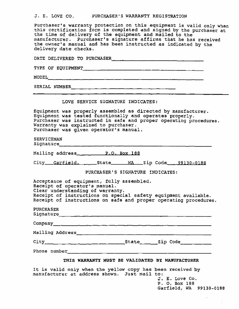
Purchaser's warranty protection on this equipment is valid only when this certification form is completed and signed by the purchaser at the time of delivery of the equipment and mailed to the manufacturer. Purchaser's signature affirms that he has received the owner's manual and has been instructed as indicated by the delivery date checks.
DATE DELIVERED TO PURCHAsER. ____________________________ _
TYPE OF EQUIPMENT ______________________________________ __
MODEL. ____________________________________________________ __
SERIAL NUMBER~ __________________________________ _
LOVE SERVICE SIGNATURE INDICATES:
Equipment was properly assembled as directed by manufacturer. Equipment was tested functionally and operates properly. Purchaser was instructed in safe and proper operating procedures. Warranty was explained to purchaser. Purchaser was given operator's manual.
SERVICEMAN Signature. ______________________________________________________ __
Mailing address, __________ ~P~.O~. __ B~Q~x~1~8~8
City __ ~G~a~r~f~i~e~l~d~, ______ State, ______ ~WuA ___ zip Code. ____ ~9~9~1~3~O_-~O~1~8~8
PURCHASER'S SIGNATURE INDICATES:
Acceptance of equipment, fully assembled. Receipt of operator's manual. Clear understanding of warranty. Receipt of instructions on special safety equipment available. Receipt of instructions on safe and proper operating procedures.
PURCHASER Signature ______________________________________________________ __
Company ________________________________________________________ __
Mailing Address ________________________________________________ __
City ______________________________ State ______ Zip Code __________ _
Phone number ____________________________________________________ _
THIS WARRANTY MUST BE VALIDATED BY MABUFACTURER
It is valid only when the yellow copy has been received by manufacturer at address shown. Just mail to:
J. E. Love Co. P. o. Box 188 Garfield, WA 99130-0188
J. E. LOVE CO. PURCHASER'S WARRANTY REGISTRATION
Purchaser's warranty protection on this equipment is valid only when this certification form is completed and signed by the purchaser at the time of delivery of the equipment and mailed to the manufacturer. Purchaser's signature affirms that he has received the owner's manual and has been instructed as indicated by the delivery date checks.
DATE DELIVERED TO PURCHAsER. ____________________________ _
TYPE OF EQUIPMENT ______________________________________ __
MODEL. ____________________________________________________ __
SERIAL NUMBER~ __________________________________ _
LOVE SERVICE SIGNATURE INDICATES:
Equipment was properly assembled as directed by manufacturer. Equipment was tested functionally and operates properly. Purchaser was instructed in safe and proper operating procedures. Warranty was explained to purchaser. Purchaser was given operator's manual.
SERVICEMAN Signature. ______________________________________________________ __
Mailing address, __________ ~P~.O~. __ B~Q~x~1~8~8
City __ ~G~a~r~f~i~e~l~d~, ______ State, ______ ~WuA ___ zip Code. ____ ~9~9~1~3~O_-~O~1~8~8
PURCHASER'S SIGNATURE INDICATES:
Acceptance of equipment, fully assembled. Receipt of operator's manual. Clear understanding of warranty. Receipt of instructions on special safety equipment available. Receipt of instructions on safe and proper operating procedures.
PURCHASER Signature ______________________________________________________ __
Company ________________________________________________________ __
Mailing Address ________________________________________________ __
City ______________________________ State ______ Zip Code __________ _
Phone number ____________________________________________________ _
THIS WARRANTY MUST BE VALIDATED BY MABUFACTURER
It is valid only when the yellow copy has been received by manufacturer at address shown. Just mail to:
J. E. Love Co. P. o. Box 188 Garfield, WA 99130-0188

· 4+4 CULTIVATOR 5 Section
1

Table of Contents
Title
Important Safety Information. Warranty Purchasers Warranty Regrestration and claims procedure
Page
Index -----------------------------------------------------------------1,3
F rame layout ---------------------------------------------------------------------- 4,5 Center frame, Tongue, Cross tongue & Forward shank mount ------------ 6,7 Inner wing' frame, Left, Wing pull & Forward shank mount --------------- 8,9 Inner wing frame, Right, Wing pull & forward shank mount -------------- 10,11 Outer wing frame, Left ---------------------------------------------------------- 12,13 Outer wing frame, Right -------------------------------------------------------- 14,15 Caster wheel leg assembly, Left [Forward floation] ------------------------ 16,17 Caster wheel leg assembly, Right [Forward floation] ---------------------- 18,19 Tandem wheel leg assembly, Center frame, Left, 8 bolt hubs ------------- 20,21 Tandem wheel leg assembly, Center frame, Right, 8 bolt hubs ------------ 22,23 Wheel leg walking beam assembly, Center frame, 8 bolt hubs ------------ 24,25 Tandem wheel leg assembly, Inner wing, Right, 6 bolt hubs -------------- 26,27 Tandem wheel leg assembly, Inner wing, Left, 6 bolt hubs ---------------- 28,29 Tandem wheel leg assembly, Outer wing, right, 6 bolt hubs --------------- 30,31 Tandem wheel leg assembly, Outer wing, Left, 6 bolt hubs ---------------- 32,33 Tandem wheel leg assemblies, Wing frames, 6 bolt hubs ------------------- 34,35 Tandem wheel leg Walking beams Hubs & Spindles 6 bolt -------------- 36 37 , , , , Adjustable linkage assembly, Hydraulic cylinders & Locks ---------------- 38,39 Main lift hydraulic components ------------------------------------------------ 40,41 Main lift system hydraulic cylinders & depth control stops ----------------- 42,43 Wing lift components, Center frame ------------------------------------------- 44,45 Wing lift components, Inner wing, Left ---------------------------------------- 46,47 Wing lift components, Inner wing, Right -------------------------------------- 48,49 Transport latch Wing transport stand ------------------------------------------- 50,51 Wing lift components, Inner wing, Left, 1400-500 Series -------------------- 52,53 Wing lift components, Inner wing, Right, 1400-500 Series ------------------- 54,55 Transport latch, 1400-500 Series ------------------------------------------------- 56,57 Wing lift components, Outer wing, Left ----------------------------------------- 58,59 Wing lift components, Outer wing, Right --------------------------------------- 60,61
2 Cultivator, 5 Section
Table of contents
Title Page
Hydraulic wing lift components, Center frame --------------------------------- 62,63 Hydraulic components, Wing lift Inner & Outer frames, Left ---------------- 64,65 Hydraulic components, Wing lift Inner & Outer frames, Right -------------- 66,67 Fixed shank assembly ------------------------------------------------------"-------- 68,69 Cultivator shank layout, 9in spacing, 50Ft ---------------------------------------- 70 Cultivator shank layout, 7 in spacing, 50Ft ---------------------------------------- 71 Cultivator shank layout, 7in spacing, 45Ft ----------------------------------------72 Blank page ----------------------------------------------------------------------------- 73
Wing extension components, 2, 4 & 6 shanks ----------------------------------74,75 Wing extension components, 8 shanks ------------------------------------------ 76,77 Wing extension components, 8 shanks, 7in spacing -------------------------- 78,79 Wing extension components, 10 shanks ---------------------------------------- 80,81 Wing extension components, 10 shanks, 7in spacing -----------.--------.----- 82,83 Wing extension components 12 & 14 shanks --------------------.-------------- 84,85 Wing extension components, 12 shanks, 7in spacing -----------.-------------- 86,87 Wing extension components, 14 shanks, 7in spacing ------------------------ 88,89 Harrow mount extension, 6 shanks or less, 45Ft & 50Ft. -------------------- 90,91 Harrow mount extension, 8 shanks or more, 50Ft. ---------------------------- 92,93
Parts numbers Page reference ----------------------------------------------A-l thru A-8
Cultivator, 5 Section 3
Frame Layout
4 CallcilUi Cultivator, 5 Section

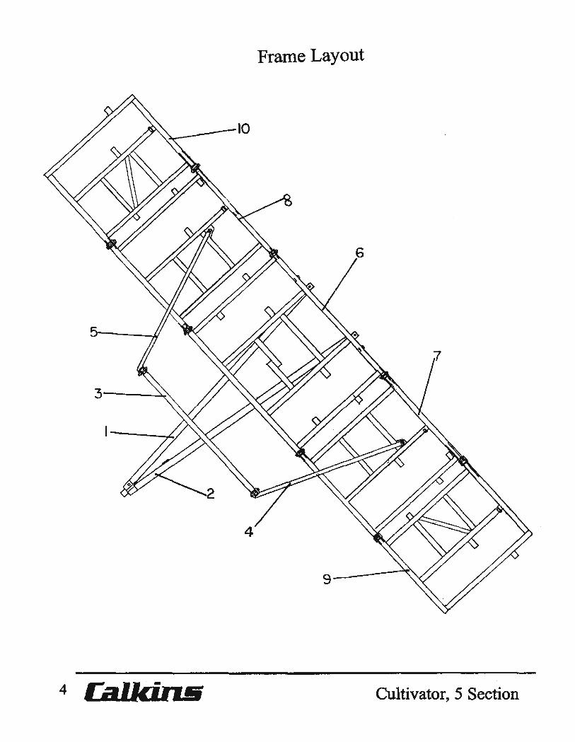
Frame Layout
Key Part No. Description
1 0403-004 Tongue, right side 2 0403-005 Tongue, left side 3 0403-020 Cross tongue 4 0403-025 Wing pull, left, 12ft.
0403-027 Wing pull, left, 9-1I2ft. 5 0403-026 Wing pull, right, 12ft.
0403-028 Wing pull, right, 9-l/2ft. 6 0403-035 Center frame, 12ft. 7 0403-036 Inner wing frame, left, 12ft.
0403-038 Inner wing frame, left, 9-1 12ft.
8 0403-037 Inner wing frame, right, 12ft. 0403-039 Inner wing frame, right, 9-1I2ft.
9 0403-040 Outer wing frame, left, 7ft. 10 0403-041 Outer wing frame, right, 7ft.
45 Ft. 50 Ft.
12 Ft. Center 12 Ft. Center 9-1/2 Ft. Inner wings 7 Ft. Outer wings
12 Ft. Inner wings 7 Ft. Outer wings
Cultivator,5 Section J.e. LOVE COMPANY 5 -_." •
Center frame, Tongue, Cross tongue & Forward shank mount
6 Cultivator,5 Section
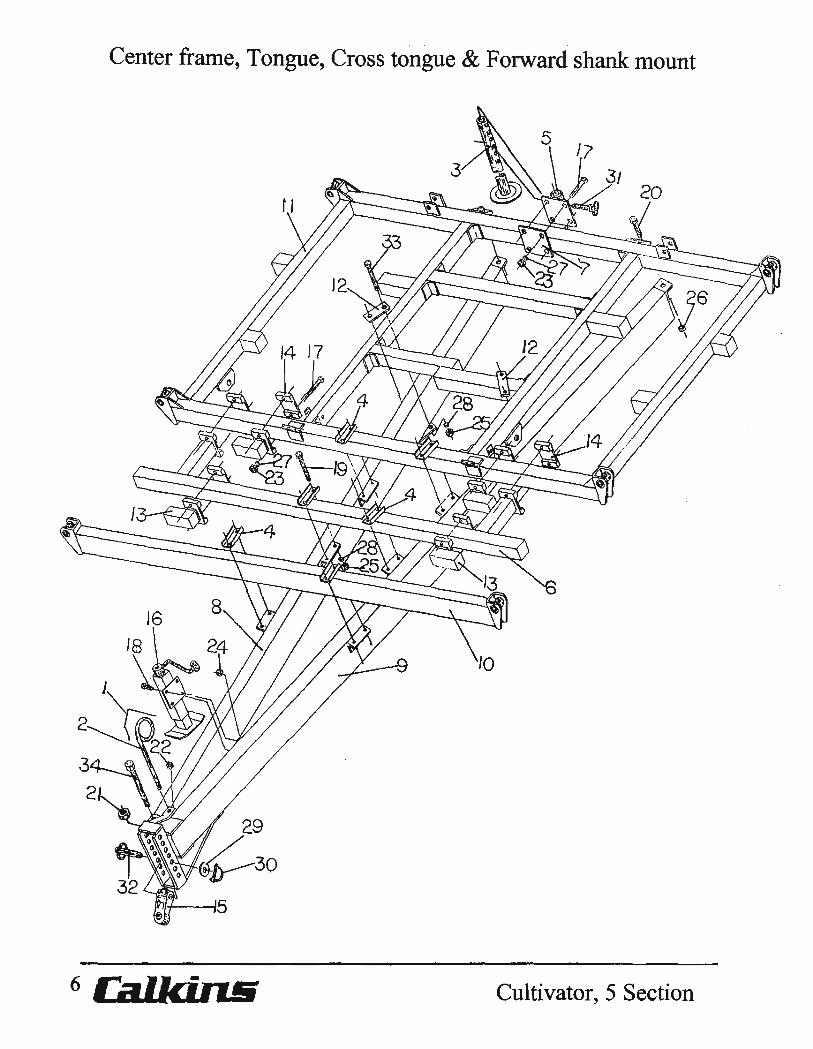
Center frame, Tongue, Cross tongue & Forward shank mount
Key Part No.
1 0101-037 2 0106--211 3 0201-065 4 0206-031 5 0400-062 6 0400-082 7 0400-955 8 0403-004 9 0403-005 10 0403-020 11 0403-035 12 0403-296 13 0400-085 14 0410-079 15 5919-900 16 6329-005 17 7114-055 18 7114-109 19 7115-076 20 7116-030 21 7717-255 22 7723-015 23 7724-005 24 7724-120 25 7725-002 26 7726-012 27 7844-020 28 7845-020 29 7896-500 30 7920-006 31 7920-012 32 8036-025 33 8115-013 34 8116-006
Cultivator, 5 Section
Description
Hydraulic hose mast assembly Hydraulic hose mast Rear stand, 42-1/2" Clamp plate, 4-3/4" span, WI 3/4" holes Rear stand adjustment bracket Forward shank mount, center frame Mount plate Tongue, right side Tongue, left side Cross tongue Center frame, 12 ft. Tongue brace plate 8"- 90 degree, bolt on shank mount. Base plate Tongue pull eye Tongue jack, agricultural Cap screw, 5/8''NC x 5-1/2" Cap screw, 5/8''NC x 2" Cap screw, 3/4''NC x 6" Cap screw, 1 ''NC x 3" Hex Nylock nut, 1-1/4''NC Hex lock nut, 1/2"NC Hex nut, 5/8"NC Hex lock nut, 5/8''NC Hex nut, 3/4''NC Hex Nylock nut, 1 ''NC Lock washer, 5/8" Lock washer, 3/4" Machine bushing, 1-112" x 10 gao NR Lock pin, pull eye Snap pin, 112" x 4" Pin, tongue pull eye, 1-112" x 5-112" Cap screw, 3/4''NC x 14-112" Bolt, 1-1I4''NC x 10-112", WI Nylock nut
J.E. LOVE COMPANY 7
_(I)trll®
Inner wing frame, Left, Wing pull & Forward shank mount
8 Ca.l.lciruii Cultivator, 5 Section
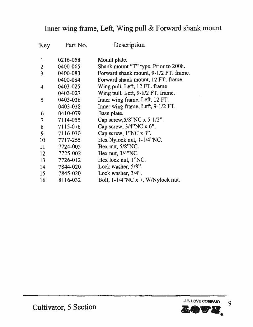
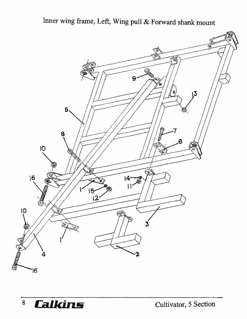
Inner wing frame, Left, Wing pull & Forward shank mount
Key Part No. Description
1 0216-058 Mount plate. 2 0400-065 Shank mount "T" type. Prior to 2008. 3 0400-083 Forward shank mount, 9-112 FT. frame.
0400-084 Forward shank mount, 12 FT. frame 4 0403-025 Wing pull, Left, 12 FT. frame
0403-027 Wing pull, Left:, 9-1/2 FT. frame. 5 0403-036 Inner wing frame, Left, 12 FT.
0403-038 Inner wing frame, Left:, 9-112 FT. 6 0410-079 Base plate. 7 7114-055 Cap screw,5/8''NC x 5-1/2". 8 7115-076 Cap screw, 3/4''NC x 6". 9 7116-030 Cap screw, 1 "NC x 3". 10 7717-255 Hex Ny10ck nut, 1-1/4''NC. 11 7724-005 Hex nut, 5/8''NC. 12 7725-002 Hex nut, 3/4 "NC. 13 7726-012 Hex lock nut, 1 ''NC. 14 7844-020 Lock washer, 5/8". 15 7845-020 Lock washer, 3/4". 16 8116-032 Bolt, l-1I4''NC x 7, W/Nylock nut.
Cultivator,5 Section J.E. LOVE COMPANY 9
.a.
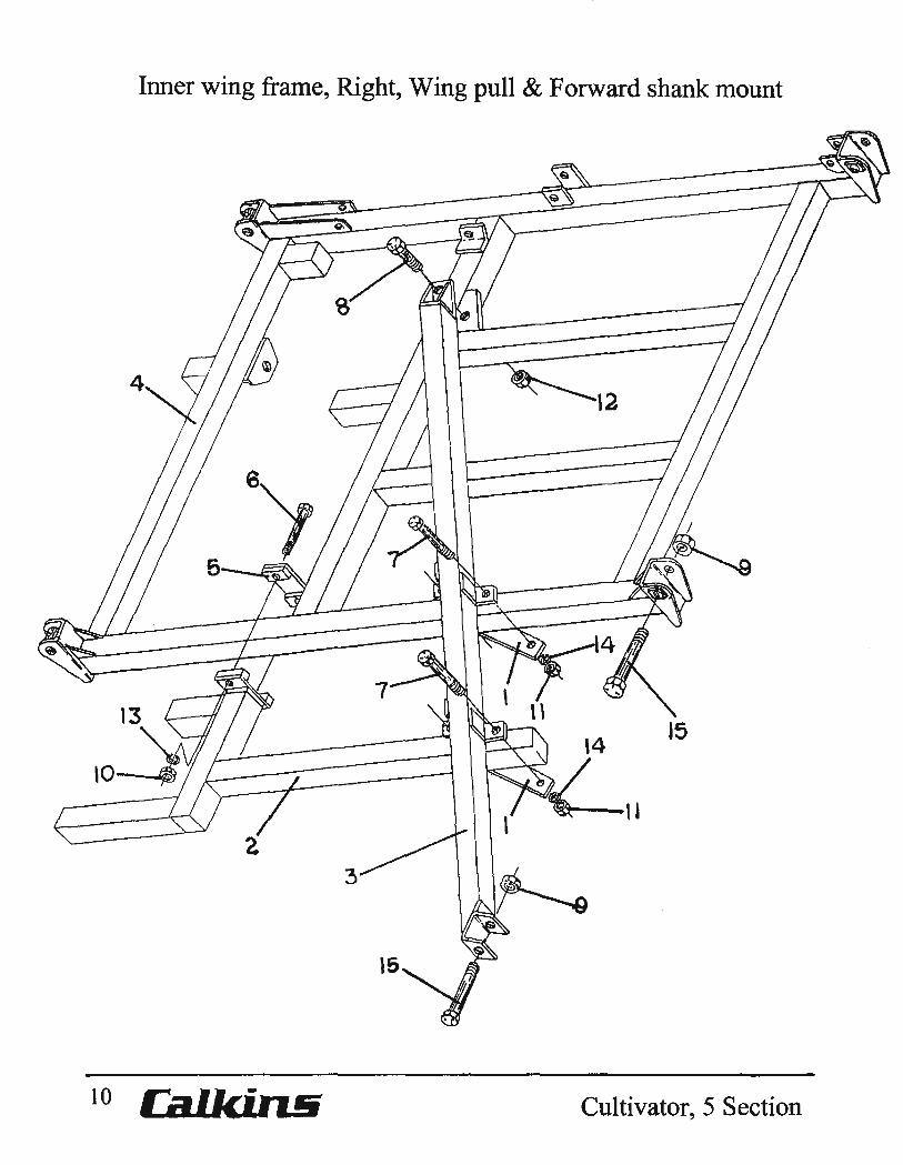
Inner wing frame, Right, Wing pull & Forward shank mount
Key Part No. Description
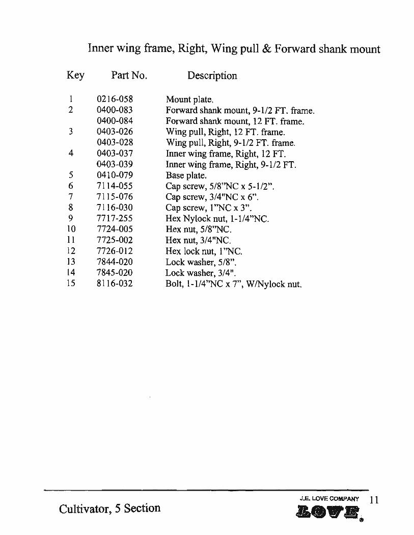
1 0216-058 Mount plate. 2 0400-083 Forward shank mount, 9-1/2 FT. frame.
0400-084 Forward shank mount, 12 FT. frame. 3 0403-026 Wing pull, Right, 12 FT. frame.
0403-028 Wing pull, Right, 9-1/2 FT. frame. 4 0403-037 Inner wing frame, Right, 12 FT.
0403-039 Inner wing frame, Right, 9-112 FT. 5 0410-079 Base plate. 6 7114-055 Cap screw, 5/8''NC x 5-112". 7 7115-076 Cap screw, 3/411NC x 6". 8 7116-030 Cap screw, 1 ''NC x 3". 9 7717-255 Hex Nylock nut, 1-1I4''NC. 10 7724-005 Hex nut, 5/8''NC. 11 7725-002 Hex nut, 3/4 11NC. 12 7726-012 Hex lock nut, 1 ''NC. 13 7844-020 Lock washer, 5/8". 14 7845-020 Lock washer, 3/4". 15 8116-032 Bolt, 1-1I4''NC x 7", W/Nylock nut.
Cultivator,5 Section J.E. LOVE COMPANY 11
--"'''8
Key
1 2 3 4 5 6 7 8 9
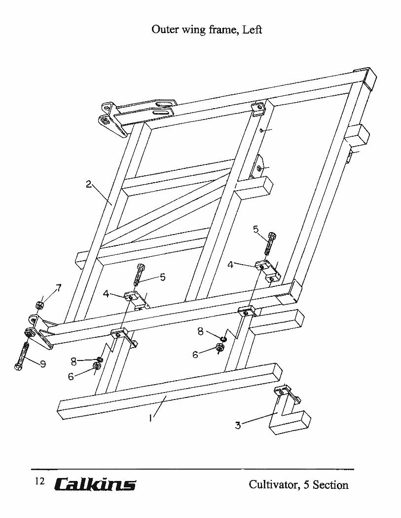
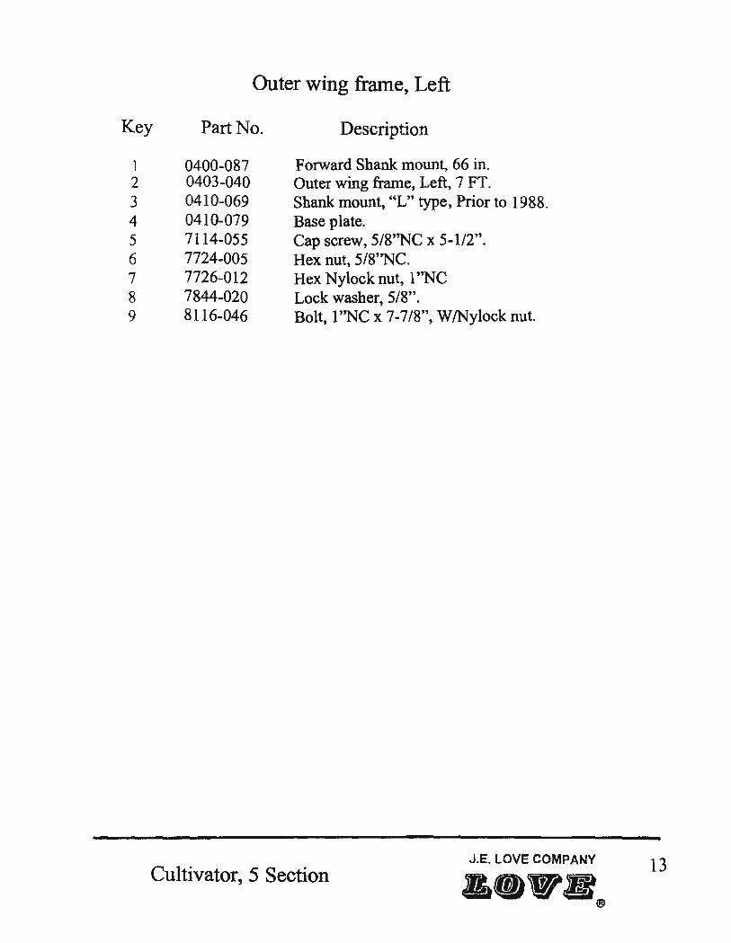
Outer wing frame, Left
Part No.
0400-087 0403-040 0410-069 0410-079 7114-055 7724-005 7726-012 7844-020 8116-046
Description
F olWard Shank mount, 66 in. Outer wing frame, Left, 7 FT. Shank mount, "L" type, Prior to 1988. Base plate. Cap screw, 5/8"NC x 5-112". Hex nut, 5/8"NC. Hex Nylock nut, 1 ''NC Lock washer, 5/8". Bolt, l''NC x 7-7/8", W/Nylock nut.
J.E. LOVE COMPANY
Cultivator, 5 Section 13
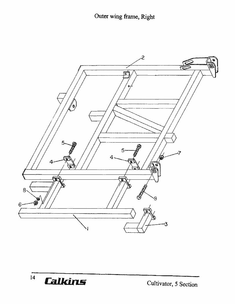
Outer wing frame, Right
14 Cultivator, 5 Section
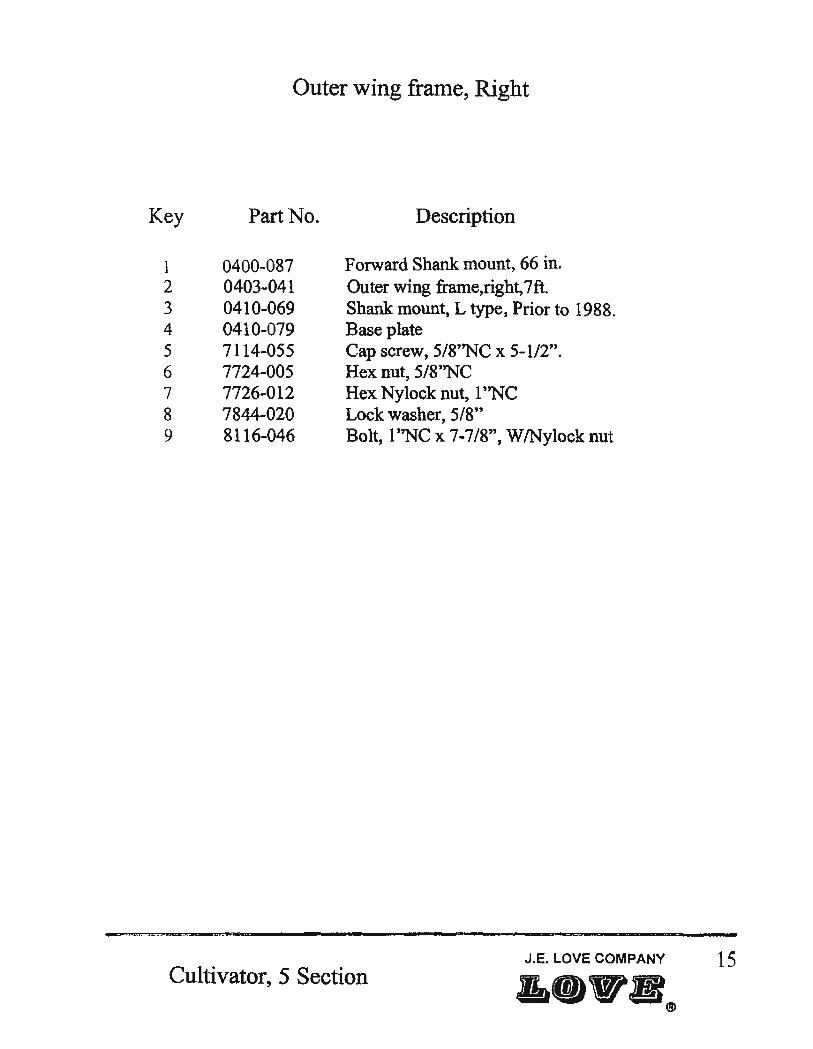
Outer wing frame, Right
Key Part No. Description
1 0400-087 Forward Shank mount, 66 in. 2 0403-041 Outer wing frame, right, 7ft. 3 0410-069 Shank mount, L type, Prior to 1988. 4 0410-079 Base plate 5 7114-055 Cap screw, 5/8''NC x 5-112". 6 7724-005 Hex nut, 5/8''NC 7 7726-012 Hex Nylock nut, 1 ''NC 8 7844-020 Lock washer, 5/8" 9 8116-046 Bolt, 1''NC x 7-7/8", W/Nylock nut
Cultivator, 5 Section J.E. LOVE COMPANY 15
•• W.(~
Caster wheel leg assembly, Left [F orward floatation]
Cultivator, 5 Section

Key
1 2 3 4 5 6 7 8 9 10 11 12 13 14 15 16
17 18 19 20 21 22 23 24 25 26 27 28 29 30 31
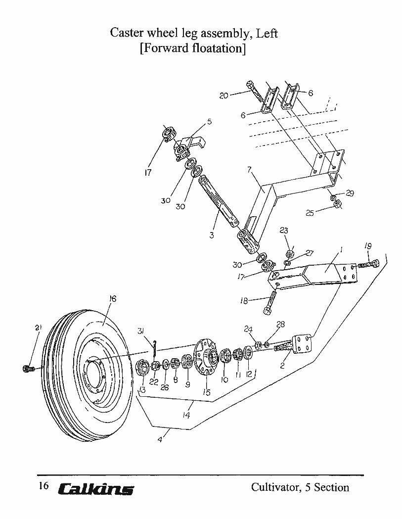
Caster wheel leg assembly, Left [Forward floatation]
Part No. Description
CW9-030 Caster Wheel Leg, LH CW9-034 Spindle Platform CW9-045 Shaft, 1·5/S" x 1S" CW9-555 Caster Wheel Leg Assembly. LH 0200-147 limit Plate 0206-031 Clamp Plate. 4" Span, 3/4" Bolts. Formed 0410-118 Depth Wheel Arm 5419-113 Outer Bearing 5419-118 Outer Cup 5419-141 Inner Cup 5419-142 Inner Bearing 5439-141 Seal 5469-006 Dust Cap 5619-021 Hub Assembly, 6-Bolt 5619-022 Hub, 6 Bolt 5639-029 Tire & Wheel. 7.60 x 15, 8 Ply Rib
5639-421 Wheel, 15 x 6H, 6 bolt 5649-009 Tire, 7.60 x 15, 8 Ply Ag Ribbed 6487-007 Set Collar, 1-11/16" 7113-121 Capscrew. 1/2" NC x 3-3/4" 7114-030 Capscrew, 5/S" NC x 3-1/2" 7115-076 Capscrew, 3/4" NC x 6'1
7333-006 Lug Bolt, 1/2" x 1" n15-S75 Slotted Nut, 7/S" NF 7723-015 Hex Nut, 1/2" NC 7724-005 Hex Nut. 5/S" NC 7725-002 Hex Nut. 3/4" NC 7815-014 Flatwasher, 7/S" A-325 Hardened 7843-015 Lockwasher, 1/2" 7844-020 Lockwasher, 5/8" 7845-020 Lockwasher, 3/4" 7897-015 Machine Bushing, 1-5/8" 10GA NR 7910-162 Cotter Pin, 5/32 x 1-112"
Cultivator, 5 Section J.E.LOVE COMPANY 17 &-"-8
Caster wheel leg assembly, Right [ Forward floatation]
~20 ~\1
9
18 Ca..IkiruJ Cultivator, 5 Section

Key
1 2 3 4 S 6 7 8 9
10 11 12 13 14 15 16 17 18 19 20 21
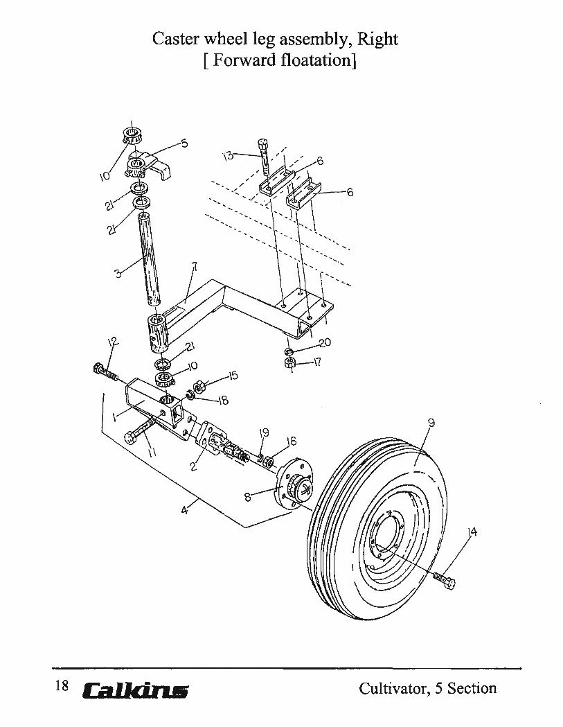
Caster wheel leg assembly, Right [ F orward floatation]
Part No. Description
CW9-031 Caster Wheel Leg, RH CW9-034 Spindle Platform CW9-045 Shaft, 1-5/8" x 18" CW9-S56 Caster Wheel Leg Assembly, RH 0200-147 Umit Plate 0206-031 Clamp Plate, 4" Span, 3/4" Bolts, Formed 0410-118 Depth Wheel Arm 5619-021 Hub Assembly, 6 Bolt 5639-029 Tire & Wheel, 7.60 x 15, 8 Ply Rib
5639-421 Wheel, 15 x 6H, 6 bolt 5649-009 Tire, 7.60 x 15,8 Ply Ag Ribbed
6487-007 Set Collar, 1-11/16" 7113-1-21 Capscrew, 112" NC x 3-3/4" 7114-030 Capscrew, 5/8" NC x 3-1/2" 7115-076 Capscrew, 3/4" NC x 6" 7333-006 Lug Bolt, 112" NF x 1" 7723-015 Hex Nut, 1/2" NC 7724-005 Hex Nut, 518" NC 7725-002 Hex Nut, 3/4" NC 7843-015 Lockwasher, 112" 7844-020 Lockwasher, 518" 7845-020 Lockwasher, 3/4" 7897-015 Machine Bushing, 1-S/8" 10GA NR
Cultivator, 5 Section J.E. LOVE COMPANY 19

20
Tandem wheel leg assembly, Center frame, Left 8 Bolt Hubs
Calkin& Cultivator, 5 Section

Key
1 2 3 4 5
6
7 8 9 10 11 12 13 14 15
16 17 18 19
Tandem wheel leg assembly, Center frame, Left 8 Bolt Hubs
Part No. Description
0400-025 Pivot arm 0403-035 Center frame 0403-052 Center frame wheel leg, left, W 10 Spindle. 0403 w 385 Center frame wheel leg, left, W /Walking beam 0403-400 Center frame walking beam assembly W /Hubs and
Spindles, left. 0400-040 Center frame walking beam W 10 Hubs & Spindles. 0410-103 Cylinder lock, used on Center frame cylinders only.
5818w 060 and 5818-061 0410-581 Adjustable linkage assembly. 5818-060 Hydraulic cylinder, 4-3/4 x 8, AB 1238. 5846-095 112" O-Ring 90 degree swivel union. 6136-675 Bushing, 1.75" OD x 1.531" ID x l.43 8". 7115-025 Cap screw, 3/4"NC x 2-112". 7115-050 Cap screw, 3/4"NC x 5". 7717-555 Hex Nylock nut, 1-1/2''NC. 7725-002 Hex nut, 3/4"NC. 7816-020 Cut washer, 1", Pivot link.
[ position inboard toward center line] 7845-020 Lockwasher, 3/4". 7896-500 Maching bushing, 1-1/2" x 10 Ga. NR. 7920-002 Hitch pin, #8, cylinder lock. 8116-803 Bolt, l-1I2''NC x 4-118", W17717-555 Nylock nut.
Cultivator, 5 Section J.E. lOVE COMPANY
&_Y5(~ 21
22
Tandem wheel leg assembly, Center frame, Right 8 Bolt Hubs
Cultivator,5 Section

Tandem wheel leg assembly, Center frame, Right 8 Bolt Hubs
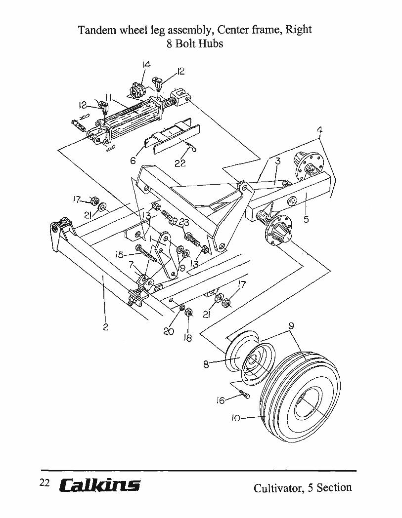
Key Part No. Description
1 0400-025 Pivot arm 2 0403-035 Center frame, [CF]. 3 0403-053 CF Wheel leg, Right, W 10 Spindle. 4 0403-390 CF Wheel leg assembly, Right, W/Walking beam. S 0403-395 CF Walking beam assembly,Right, WlHubs.
0400-041 CF Walking beam, Right, W/5419-122 Races. 6 0410-103 Cylinder lock, used on 5818-061 and 5818-060 CF
Hydraulic cylinders. 7 0410-581 Adjustable linkage assembly. 8 5639-426 Wheel, 15x8, 8 Bolt hub. 9 5639-584 Tire mounted, 5639-426 Wheel W 15649-062 tire.
5639-589 Tire mounted, 5639-426 Wheel W 15649-503 tire. 10 5649-062 Tire, 9.5L x 15, 8 Ply, Ribbed implement.
5649-503 Tire, 11 L x 15, 8 Ply, Ribbed implement. 1 1 5818-061 Hydraulic cylinder, [ABI232] 5x8 CF Right. 12 5846-095 112" a-Ring 90 degree Swivel union. 13 6136-675 Bushing, 1.75" 00 x 1.531" 10 x 1.438". 14 6899-402 Medium size A Depth stop kit, 5 sizes 1" thru 2",
use W Irod diameter 1" thru 1.5". 6899-502 Large size B Depth stop kit, 5 sizes 1" thru 2",
Use Wlrod diameter 1" thru 2". 15 7115-050 Cap screw, 3/4 11NC x 5". 16 7333-009 Bevel head Lug bolt, 9/16''NF x 1-114". 17 7717-555 Hex Nylock nut, I-1I2''NC. 18 7725-002 Hex nut, 3/4NC. 19 7816-020 Cut washers, pivot link, 1".
Position inboard toward center line. 20 7845-020 Lock washer, 3/4". 21 7896-500 Machine bushing, 1-112" x 10 gao NR 22 7920-002 Hitch pin #8, cylinder lock. 23 8116-803 Bolt, 1-1I2''NC x 4-118", W17717-555 Nylock nut.
J.E. LOVE COMPANY 23 Cultivator, 5 Section ",11
8

24
Wheel leg Walking beam assembly, Center frame, 8 Bolt Hubs
Cultivator,5 Section
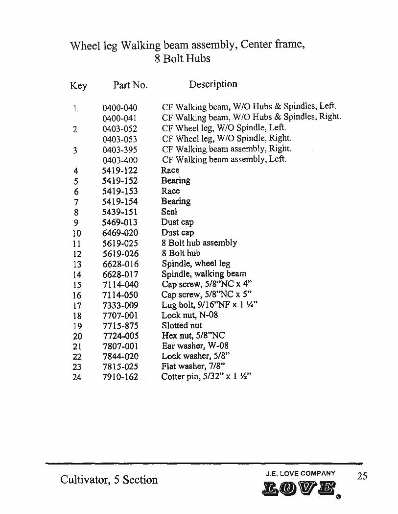
Wheel leg Walking beam assembly, Center frame, 8 Bolt Hubs
Key
1
2
3
4 5 6 7 8 9 10 11 12 13 14 15 16 17 18 19 20 21 22 23 24
Part No.
0400~040
0400~041
0403~052
0403-053 0403-395 0403-400 5419-122 5419-152 5419-153 5419-154 5439-151 5469-013 6469-020 5619-025 5619-026 6628-016 6628-017 7114-040 7114-050 7333-009 7707-001 7715-875 7724-005 7807-001 7844-020 7815-025 7910-162
Cultivator, 5 Section
Description
CF Walking beam, W 10 Hubs & Spindles, Left. CF Walking beam, WIO Hubs & Spindles, Right. CF Wheel leg, W 10 Spindle, Left. CF Wheel leg, W 10 Spindle, Right. CF Walking beam assembly, Right. CF Walking beam assembly, Left. Race Bearing Race Bearing Seal Dust cap Dust cap 8 Bolt hub assembly 8 Bolt hub Spindle, wheel leg Spindle, walking beam Cap screw, 5/S"NC x 4" Cap screw, 5/8''NC x 5" Lug bolt, 9/16t 'NF x 1 y..n Lock nut, N-08 Slotted nut Hex nut, 5/S"NC Ear washer, W-08 Lock washer, 5/8" Flat washer, 7/8" Cotter pin, 5/32" x 1 Yl"
J.E. LOVE COMPANY 25

Tandem wheel leg assembly, Inner wing, Right
3
26 Cal.Icin.tfi Cultivator, 5 Section

Key
1 2
3
4 5 6 7 8 9 10
11 12 13 14 15
Tandem wheel leg assembly, Inner wing, Right 6Bolt Hubs
Part No. Description
0400-025 Pivot ann. 0400-549 Wheel leg assembly, Right, W/walking beam &
6 bolt hubs 0403-037 Inner wing frame, Right, 12 FT. 0403-039 Inner wing frame, Right, 9-112 FT. 0410-581 Adjustable link assembly. 5818-057 Hydraulic cylinder, 3-3/4 x 8, [AB1256]. 5846-095 112" 90 degree O-Ring swivel union. 6136-627 Bushing, l-1I2"OD x 1-9/32"ID x 7/16". 7115-025 Cap screw, 3/4''NC x 2-112". 7115-050 Cap screw, 3/4''NC x 5". 7816-020 Cut washer, 1", Pivot link.
Locate inboard toward the center line. 7717-255 Hex locknut, l-1I4"NC. 7725-002 Hex nut, 3/4"NC. 7845-020 Lock washer, 3/4". 7896-250 Machine bushing, 1-1/4" x 10 gao NR 8116-802 Bolt, l-1I4'~C x 3-114".
Cultivator, 5 Section J.E. LOVE COMPANY 27
trite
Tandem wheel leg assembly, Inner wing, Left 6 Bolt Hubs
28 Callcil1.!i Cultivator, 5 Section

Key
1 2
3
4 5 6 7 8 9
10 11 12 13 14
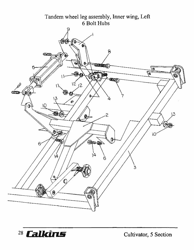
Tandem wheel leg assembly, Inner wing, Left 6 Bolt Hubs
Part No. Description
0400¥025 Pivot arm. 0400-548 Wheel leg assembly, Left, W/Walking beam &
6 bolt hubs. 0403-036 Inner wing frame, Left, 12 FT. 0403-038 Inner wing frame, Left, 9-1/2 FT. 0410-581 Adjustable link assembly. 5818-058 Hydraulic cylinder, 4 x 8 [ABI250], 20-114 RC. 6136-627 Bushing, 1-1I2"OD x 1-9/32"ID x 7/16". 7115-025 Cap screw, 3/4 11NC x 2-112". 7115-050 Cap screw, 3/4"NC x 5". 7816-020 Cut washers, 1 ", Pivot link,
Locate inboard toward center line. 7717-255 Hex Nylock nut, 1-1I4"NC. 7725-002 Hex nut, 3/4"NC. 7845-020 Lock washer, 3/4". 7896-250 Machine bushing, 1-114" x 10 gao NR. 8116-802 Bolt, 1-1I4"NC x 3-114".
Cultivator, 5 Section J.e. LOve COMPANY 29
--tr"e

Tandenl wheel leg assembly, Outer wing, Right
30 Calkin.& Cultivator, 5 Section
Tandem wheel leg assembly, Outer wing, Right
Key Part No. Description
1 0400-025 Pivot arm. 2 0400-041 Outer wing frame, Right, 7 FT. 3 0403-332 Wheel leg assembly, Right, W/Walking beam &
6 bolt hubs. 4 0410-581 Adjustable link assembly. 5 5818-056 Hydraulic cylinder, 3-112 x 8, [ABI262], 20-114 RC. 6 5846-095 112" 90 degree O-Ring swivel union. 7 6136-627 Bushing, l-1I2"OD x 1-9/32"ID x 7/16". 8 6146-013 Bushing. 9 6899-402 Medium size A Depth stop kit, 5 sizes 1" thru 2",
Use W/rod diameter 1" thru 1.5". 6899-502 Large size B Depth stop kit, 5 sizes 1" thm 2",
Use W /rod diameter 1" thru 2". 10 7115-025 Cap screw, 3/4"NC x 2-112". 11 7115-050 Cap screw, 3/4"NC x 5". 12 7816-020 Cut washer, 1" Pivot link.
Locate inboard toward center line. 13 7717-255 Hex lock nut, 1-1I4"NC. 14 7725-002 Hex nut, 3/4"NC. 15 7845-020 Lock washer, 3/4". 16 7896-250 Machine bushing, 1-1/4" x 10 gao NR. 17 8116-802 Bolt, 1-1I4"NC x 3-114".
Cultivator,5 Section JoE. LOVE COMPANY 31
&elFa.
Tandem wheel leg assenlbly, Outer wing, Left
32 Cultivator, 5 Section
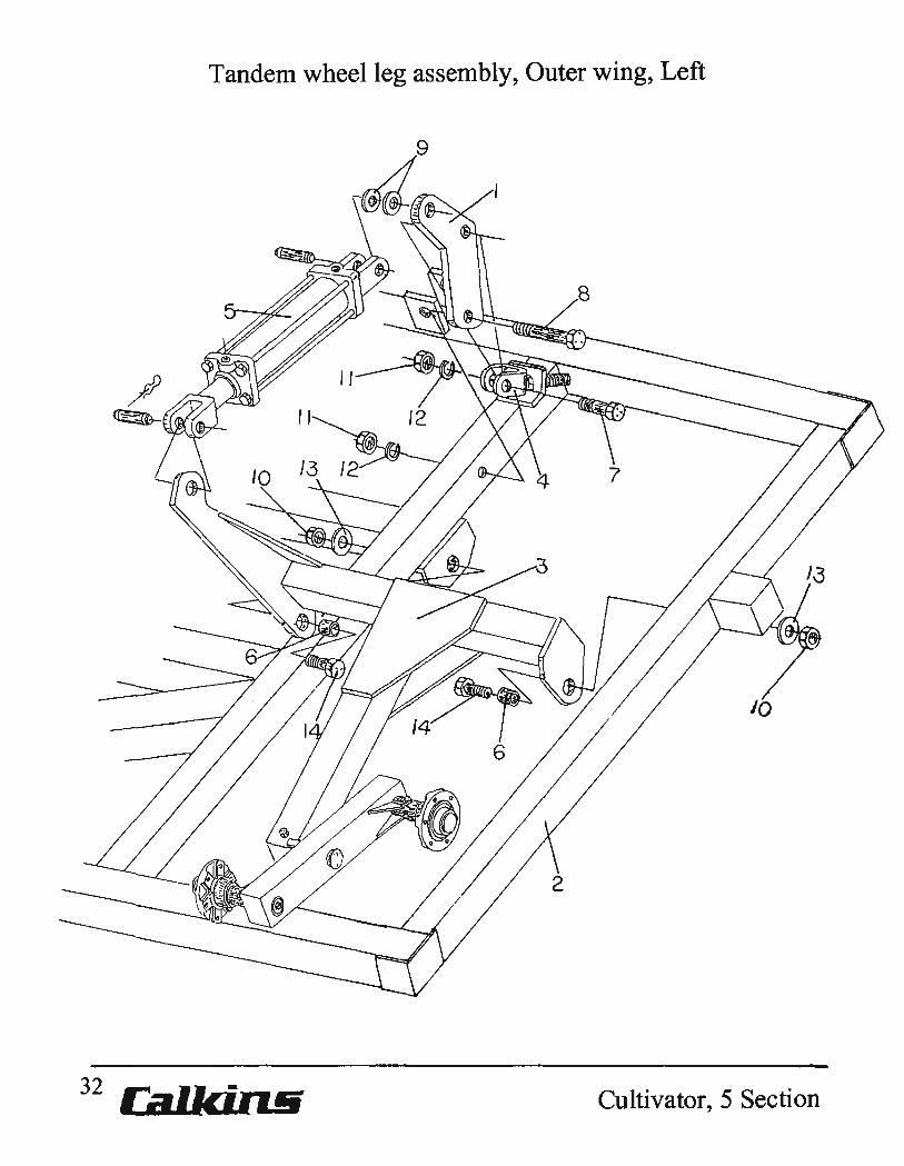
Tandem wheel leg assembly, Outer wing, Left 6 Bolt Hubs
Key Part No.
1 0400-025 2 0403-040 3 0403-333
4 0410-581 5 5818-059 6 6136-627 7 7115-025 8 7115-050 9 7816-020
10 7717-255 II 7725-002 12 7845-020 13 7896-250 14 8116-802
Description
Pivot arm. Outer wing frame, Left, 7 FT. Wheel leg assembly, Left W IW alking beam & 6 bolt hubs. Adjustable link assembly. Hydraulic cylinder, 4-112 x 8, [AB1244], 20-1/4" RC. Bushing, 1-1I2"OD x 1-9/32"ID x 7116". Cap screw, 3/4"NC x 2-112". Cap screw, 3/4"NC x 5". Cut washers, 1", Pivot link. Locate inboard toward centerline. Hex Nylock nut, 1-1I4'~C. Hex nut, 3/4'~C. Lock washer, 3/4". Machine bushing, 1-114" x 10 gao NR. Bolt, 1-1/4"NC x 3-1/4".
Cultivator, 5 Section J.E. lOVE COMPANY 33
•••

34
Tandem wheel leg assemblies, Wing frames 6 bolt hubs
'r----6
5
Cultivator, 5 Section
Key
1
2
3
4
5
6
7
8 9
10
11
Tandem wheel leg assemblies, Wing frames, 6 Bolt Hubs
Part No. Description
0400-048 Tandem wheel leg, W 10 Spindle, Inner wing, Left 0403-050 Tandem wheel leg, W/O Spindle, Outer wing, Left. 0400-049 Tandem wheel leg, W 10 Spindle, Inner wing, Right. 0403-051 Tandem wheel leg, W 10 Spindle, Outer wing, Right. 0400-050 Walking beam assembly, Inner wing, Left 0400-551 Walking beam frame only, Inner wing, Left. 0403-350 Walking beam assembly, Outer wing, Left. 0403-063 Walking beam frame only, Outer wing, Left. 0400-051 Walking beam assembly, Inner wing, Right. 0400-552 Walking beam frame only, Inner wing, Right 0403-351 Walking beam assembly, Outer wing, Right. 0403-064 Walking beam frame only, Outer wing, Right. 0400-548 Tandem wheel leg assembly, W /Walking beam, Inner
Wing, Left 0403-333 Tandem wheel leg assembly, W /Walking beam, Outer
Wing, Left. 0400-549 Tandem wheel leg assembly, W /Walking beam, Inner
Wing, Right. 0403-332 Tandem wheel leg assembly, W/Walking beam, Outer
Wing, Right. 5639-026 Mounted tire, 7.60xI5, 6 ply. Ribbed Impl. Outer wheel
Leg.s. 5639-583 Mounted tire, 9.5Lx 15,6 ply. Ribbed Impl. Inner wheel
Legs 5639-588 Mounted tire, 11Lx15, 6 ply. Ribbed Impl. Inner wheel
Legs. 5639-421 Wheel rim, 15 x 6H, F/6, 6 Bolt Hub. 5649-009 Tire, 7 .60x 15,6ply Rib Impl. 5649-060 Tire, 9.5LxI5, 6ply, Rib Impl. 5649-504 Tire, llLxl5, 6ply, Rib Impl. 6136-627 Bushing, 1-1I2"OD x 1-9/32"ID x 7116".
8116-802 Bolt, 1-1/4'~C x 3-1/4".
Cultivator, 5 Section J.E. LOVE COMPANY 35
ae1FBe
36
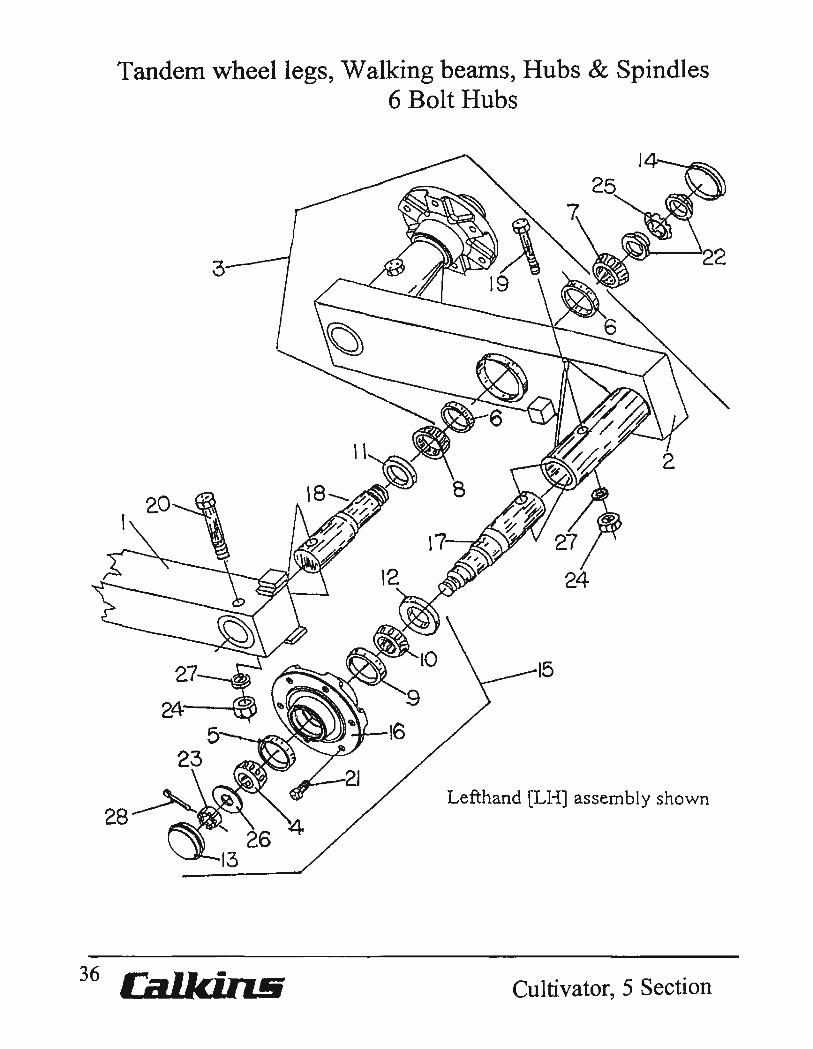
Tandem wheel legs, Walking beams, Hubs & Spindles 6 Bolt Hubs
27~ ,
24~ ~ 5
23
J4~ ........
Lefthand [LH] assembly shown
Cultivator, 5 Section

Tandem wheel legs, Walking beams, Hubs & Spindles 6 Bolt Hubs
Key Part No. Description 1 0400-048 Tandem wheel leg, WIO Spindle, Inner wing, Left.
0400-049 Tandem wheel leg, W 10 Spindle, Inner wing, Right. 0403-050 Tandem wheel leg, WIO Spindle, Outer wing, Left 0403-051 Tandem wheel leg, W 10 Spindle,Outer wing, Right.
2 0400-551 Walking beam W/5419-125 Cup, Inner wing, Left. 0400-552 Walking beam W/5419-125 Cup, Inner wing, Right. 0403-063 Walking beam W/5419-125 Cup, Outer wing, Left. 0403-064 Walking beam W/5419-125 Cup, Outer wing, Right
3 0400-050 Walking beam assembly, Inner wing, Left. 0400-051 Walking beam assembly, Inner wing, Right. 0403-350 Walking beam assembly, Outer wing, Left. 0403-351 Walking beam assembly, Outer wing, Right.
4 5419-113 Bearing, outer 5 5419-118 Cup, outer 6 5419-125 Cup,bearing race 7 5419-126 Bearing 8 5419·127 Bearing 9 5419-141 Cup, inner 10 5419-142 Bearing cone, inner 11 5439-020 Seal, wheel leg assembly 12 5439-141 Seal, 6 bolt hub 13 5469-006 Hub cap 14 6469·020 Hub cap 15 5619-021 Hub assembly, 6 bolt 16 5619·022 Hub, 6 bolt 17 5629-001 Spindle, 3650, 2-118" butt
18 6628-018 Spindle, walking beam, Inner wing frame
6628-019 Spindle, walking beam, Outer wing frame.
19 7114-040 Cap screw, 5/8H NC x 4" 20 7114·050 Cap screw, 5/8"NC x 5" 21 7333-006 Lug boJt, 'l'l"NF xl" 22 7707-001 Lock nut, N-08 23 7715-875 Slotted nut, 7/8"NF 24 7724·005 Hex nut, 5/8 t1Ne 25 7807-001 Ear washer, W -08 26 7815·014 Flat washer, 7/8" A-325 hardened 27 7844-020 Lock washer, 5/8" 28 7910-162 Cotter pin, 5/32" x 1 Y2"
Cultivator,5 Section Joe. LOVE COMPANY 37
"lie
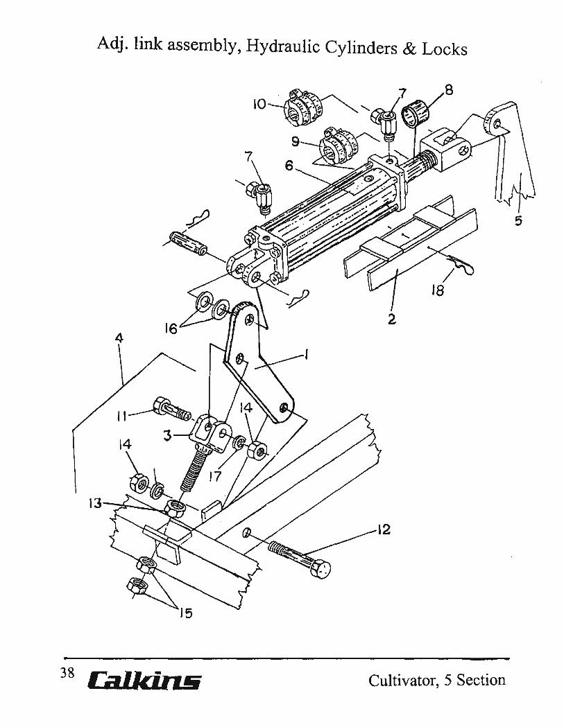
Adj. link assen1bly, Hydraulic Cylinders & Locks
38 Cultivator, 5 Section

Adj. Link assembly, Hydraulic Cylinders & Locks.
Key Part No. Description
1 0400-025 Pivot ann. 2 0410-103 Cylinder lock.
Center frame hydraulic cylinders only. 3 0410-121 Adjustable link. 4 0410-581 Adjustable link assembly. 5 -- ... _-- --- Tandem wheel leg assemblies. 6 5818-056 Hydraulic cylinder, 3-112 x 8, [ABI262] Outer wing RT
5818-057 Hydraulic cylinder, 3-3/4 x 8, [ABI256] Inner wing RT 5818-058 Hydraulic cylinder, 4 x 8, [AB 1250] Inner wing LT 5818-059 Hydraulic cylinder, 4-112 x 8, [AB1244 Outer wing LT 5818-060 Hydraulic cylinder, 4-3/4 x 8, [ABI238] Cntr frame LT 5818-061 Hydraulic cylinder, 5 x 8 [ABI232] Cntr frame RT
7 5846-095 112" O-Ring, 90 degree swivel union. 8 6146-013 Bushing. Use W/5818-056 on Outer wing RT. 9 6899-402 Medium size A Depth stop kit, 5 sizes 1" thru 2"
Use W/rod diameter 1" thru 1.5". 10 6899-502 Large size B Depth stop kit, 5 sizes I" thru 2"
Use W/rod diameter 1" thru 2" 11 7115-025 Cap screw, 3/4"NC x 2-112". 12 7115-050 Cap screw, 3/4"NC x 5". 13 7715-871 Hex nut, 7/8"NC. 14 7725-002 Hex nut, 3/4"NC. 15 7725-138 Hex jam nut, 7/8"NC. 16 7816-020 Cut washer, 1". 17 7845-020 Lock washer, 3/4". 18 7920-002 Hitch pin, #8, Cylinder lock.
Cultivator,5 Section J.E. LOVE COMPANY 39
····8
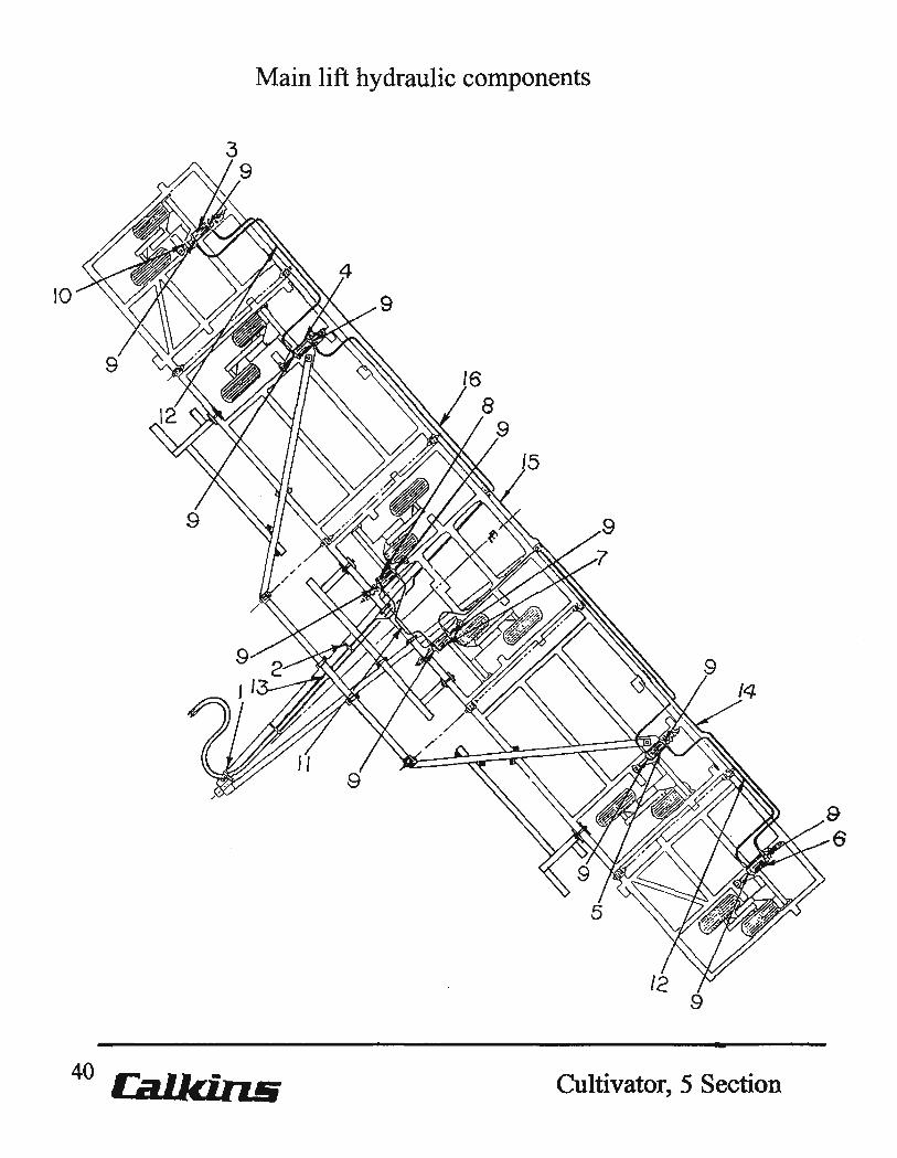
Main lift hydraulic components
10
40 Ca.lki.ns Cultivator, 5 Section
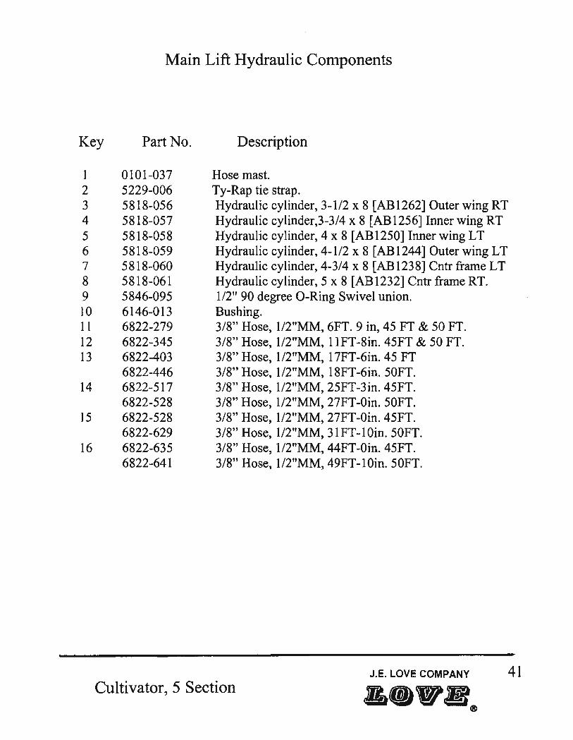
Main Lift Hydraulic Components
Key Part No.
1 0101-037 2 5229-006 3 5818-056 4 5818-057 5 5818-058 6 5818-059 7 5818-060 8 5818-061 9 5846-095 10 6146-013 II 6822-279 12 6822-345 13 6822-403
6822-446 14 6822-517
6822-528 15 6822-528
6822-629 16 6822-635
6822-641
Description
Hose mast. Ty-Rap tie strap. Hydraulic cylinder, 3-112 x 8 [AB1262] Outer wing RT Hydraulic cylinder,3-3/4 x 8 [AB1256] Inner wing RT Hydraulic cylinder, 4 x 8 [AB12S0] Inner wing LT Hydraulic cylinder, 4-112 x 8 [AB1244] Outer wing LT Hydraulic cylinder, 4-3/4 x 8 [AB 1238] Cntr frame LT Hydraulic cylinder, 5 x 8 [AB 1232] Cntr frame RT. 112" 90 degree a-Ring Swivel union. Bushing. 3/8" Hose, 1I2"MM, 6FT. 9 in, 45 FT & 50 FT. 3/8" Hose, 1I2"MM, 11FT-8in. 45FT & 50 FT. 3/8" Hose, 1/2"MM, 17FT-6in. 45 FT 3/8" Hose, 1/2"MM, 18FT-6in. 50FT. 3/8" Hose, 1I2"MM, 25FT-3in. 45FT. 3/8" Hose, 1/2"MM, 27FT-Oin. 50FT. 3/8" Hose, 1/2"MM, 27FT -Oin. 45FT. 3/8" Hose, 1I2"MM, 31FT-lOin. 50FT. 3/8" Hose, 1I2"MM, 44FT -Oin. 45FT. 3/8" Hose, 1I2"MM, 49FT-lOin. 50FT.
J.E. LOVE COMPANY 41 Cultivator, 5 Section
•• "l!I®

Main lift system Hydraulic cylinders & Depth control stops
TO LEVEL IMPLEMENT
1. MOUNT DEPTH CONTROL STOPS ON CYLINDERS AB~'I23aQ'I2e2
2.INSTALL BUSHING 6 'I46·D13 ON CYLINDERAB 12'62
AB -'I2~4
4~"OIA
5818-059
-------
o
AB-'l250 .. 4 OIA
5818-058
42 CiJ.l.kin.!i
Depth control stops-_
Bushing 6146-013
8
n_ AB-'I23B AB-1232
4j" OIA " 5 CIA
5818-060 5818-61
2 Depth Control Stops
.. ,-~
Color Code 1 in White 1-1/4 in Green 1-1/2 in Blue 1-3/4 in Red 2 in Yellow
AB-'125B
3~" CIA
5818-057
AB-'I262
3~" OIA
5818-056
Cultivator,5 Section

Main lift system Hydraulic cylinders & Depth control stops
Key Part No. Description
1 5818-056 Hydraulic cylinder, 3-1/2 x 8 AB1262, Outer wing RT 2 5818-057 Hydraulic cylinder, 3-3/4 x 8 AB1256, Inner wing RT 3 5818-058 Hydraulic cylinder, 4 x 8 AB 1250, Inner wing L T 4 5818-059 Hydraulic cylinder, 4-1/2 x 8 AB1244, Outer wing LT 5 5818-060 Hydraulic cylinder, 4-3/4 x 8 AB1238, Center frame LT 6 5818-061 Hydraulic cylinder, 5 x 8 AB1232, Center frame RT
7 6146-013 Bushing
8 6899-402 Medium size A, Depth stop kit. 6896-100 Depth stop, white 1" med. 6896-125 Depth stop, green, 1-114" med. 6896-150 Depth stop, blue, 1-112" med. 6896-175 Depth stop, red, 1-3/4" med. 6896-200 Depth stop, yellow, 2 " med.
6899-502 Large size B, Depth stop kit 6897-100 Depth stop, white, 1" large 6897-125 Depth stop, green, 1-114" large. 6897-150 Depth stop, blue, 1-112" large. 6897-175 Depth stop, red, 1-3/4" large. 6897-200 Depth stop, yellow, 2" large.
Cultivator, 5 Section J.e. LOVE COMPANY 43
A@)"B®

44
Wing lift components, center frame
7
CBllcil1.!i
\3~
\6~-: 3
15
Cultivator,5 Section
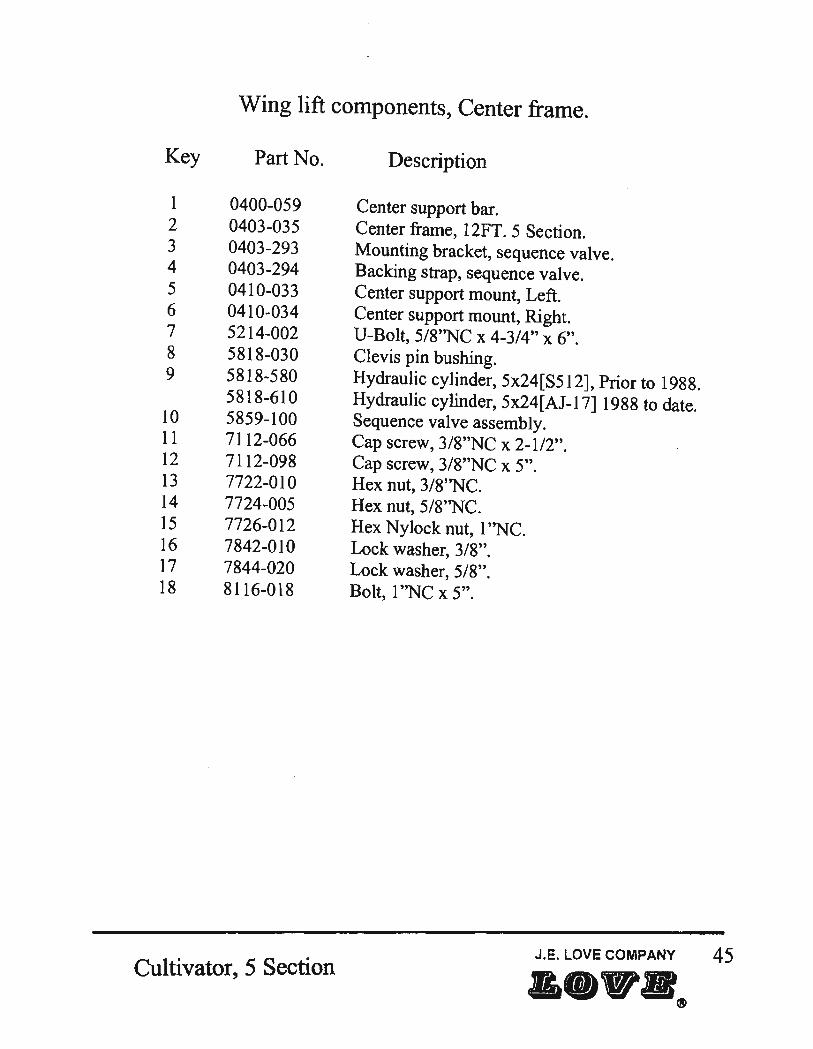
Wing lift components, Center fran1e.
Key Part No.
1 0400-059 2 0403-035 3 0403-293 4 0403-294 5 0410-033 6 0410-034 7 5214-002 8 5818-030 9 5818-580
5818-610 10 5859-100 11 7112-066 12 7112-098 13 7722-010 14 7724-005 15 7726-012 16 7842-010 17 7844-020 18 8116-018
Cultivator, 5 Section
Description
Center support bar. Center frame, 12FT. 5 Section. Mounting bracket, sequence valve. Backing strap, sequence valve. Center support mount, Left. Center support mount, Right. U-Bolt, 5/8''NC x 4-3/4" x 6". Clevis pin bushing. Hydraulic cylinder, 5x24[S512], Prior to 1988. Hydraulic cylinder, 5x24[AJ-17] 1988 to date. Sequence valve assembly. Cap screw, 3/8"NC x 2-1/2". Cap screw, 3/8"NC x 5". Hex nut, 3/8''NC. Hex nut, 5/8''NC. Hex Nylock nut, 1 ''NC. Lock washer, 3/8". Lock washer, 5/8". Bolt, 1 ''NC x 5".
J.E. LOVE COMPANY 45
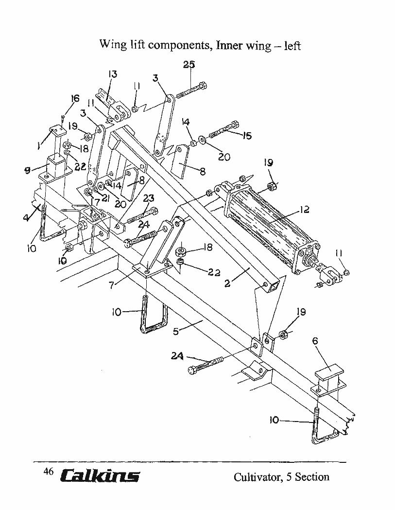
Wing lift components, Inner wing -left
13
IO-~1
10""------1-1
~:az:::;c::: ... EL2.
46 Cultivator, 5 Section
Key 1 2
3 4 5
6 7
8 9 10 11 12
13
14 15 16 17 18 19 20 21 22 23 24 25
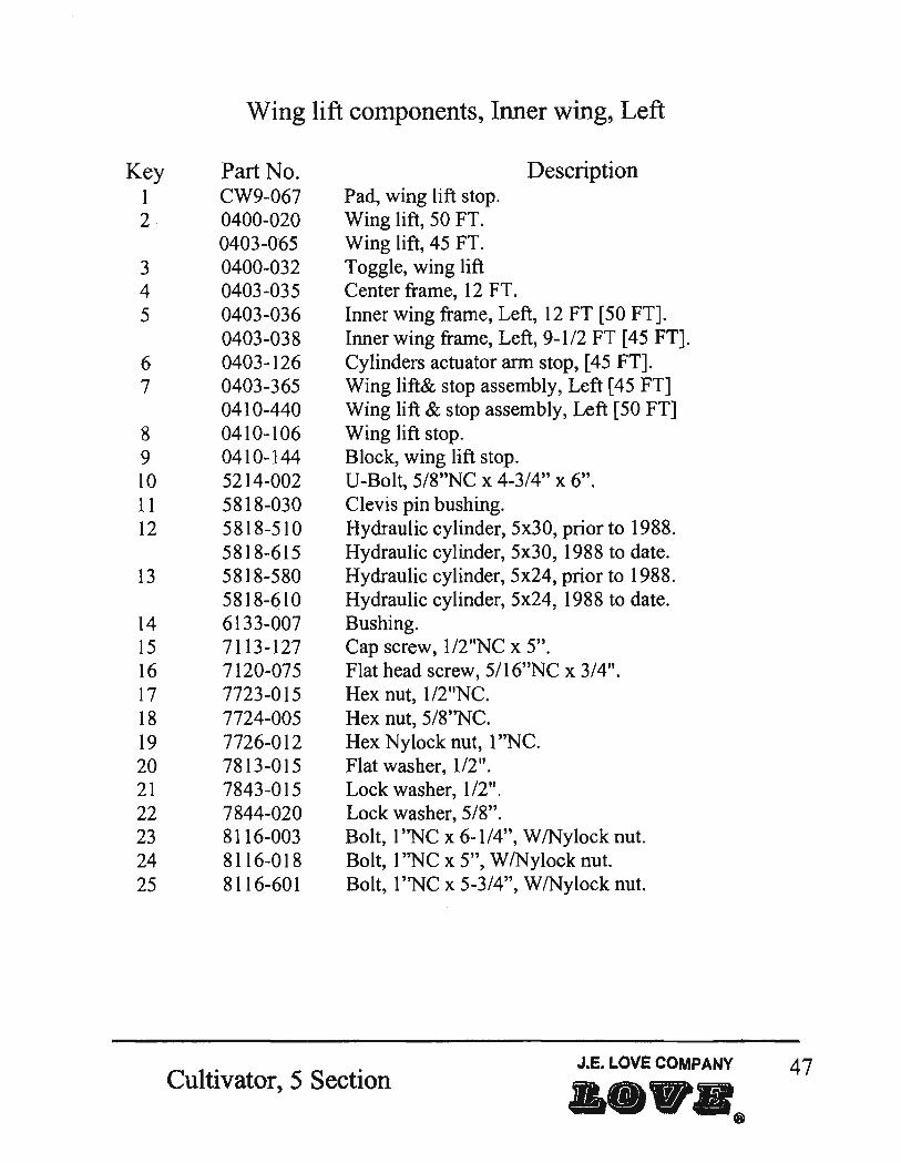
Wing lift components, Inner wing, Left
Part No. CW9-067 0400-020 0403-065 0400-032 0403-035 0403-036 0403-038 0403-126 0403-365 0410-440 0410-106 0410-144 5214-002 5818-030 5818-510 5818-615 5818-580 5818-610 6133-007 7113-127 7120-075 7723-015 7724-005 7726-012 7813-015 7843-015 7844-020 8116-003 8116-018 8116-601
Pad, wing lift stop. Wing lift, 50 FT. Wing lift, 45 FT. Toggle, wing lift Center frame, 12 FT.
Description
Inner wing frame, Left, 12 FT [50 FT]. Inner wing frame, Left, 9-1/2 FT [45 FT]. Cylinders actuator arm stop, [45 FT]. Wing lift& stop assembly, Left [45 FT] Wing lift & stop assembly, Left [50 FT] Wing lift stop. Block, wing lift stop. U-Bolt, 5/8"NC x 4-3/4" x 6". Clevis pin bushing. Hydraulic cylinder, 5x30, prior to 1988. Hydraulic cylinder, 5x30, 1988 to date. Hydraulic cylinder, 5x24, prior to 1988. Hydraulic cylinder, 5x24, 1988 to date. Bushing. Cap screw, 1I2"NC x 5". Flat head screw, 5/16''NC x 3/4". Hex nut, 1I2"NC. Hex nut, 5/8''NC. Hex Nylock nut, 1 ''NC. Flat washer, 112". Lock washer, 112". Lock washer, 5/8". Bolt, l''NC x 6-1/4", WlNylock nut. Bolt, 1 ''NC x 5", W lNylock nut. Bolt, 1 "NC x 5-3/4", WlNylock nut.
Cultivator,5 Section J.E. LOVE COMPANY 47

Wing 1ift components, Inner wing - right
2.5
4
22
48 Ca.l.k.i.rui Cultivator, 5 Section

Key 1 2
3 4 5
6 7
8 9 10 11 12
13
14 15 16 17 18 19 20 21 22 23 24 25
Wing Lift Components, Inner Wing, Right
Part No. CW9-067 0400-020 0403-065 0400-032 0403-035 0403-037 0403-039 0403-126 0403-366 0410-445 0410-106 0410-144 5214-002 5818-030 5818-510 5818-615 5818-580 5818-610 6133-007 7113-127 7120-075 7723-015 7724-005 7726-012 7813-015 7843-015 7844-020 8116-003 8116-018 8116-601
Pad, wing lift stop. Wing lift, 50 FT. Wing lift, 45 FT. Toggle, wing lift Center frame, 12 FT.
Description
Inner wing frame, Right, 12 FT [50 FT]. Inner wing frame, Right, 9-1/2 FT [45 FT]. Cylinders actuator arm stop, [45 FT]. Wing lift& stop assembly, Right [45 FTJ Wing lift & stop assembly, Right [50 FTJ Wing lift stop. Block, wing lift stop. U-Bolt, 5/8"NC x 4-3/4" x 6". Clevis pin bushing. Hydraulic cylinder, 5x30, prior to 1988. Hydraulic cylinder, 5x30, 1988 to date. Hydraulic cylinder, 5x24, prior to 1988. Hydraulic cylinder, 5x24, 1988 to date. Bushing. Cap screw, 1I2"NC x 5". Flat head screw, 5116''NC x 3/4". Hex nut, 1I2"NC. Hex nut, 5/8"NC. Hex Nylock nut, 1 ''NC. Flat washer, 112". Lock washer, 112". Lock washer, 5/8". Bolt, 1 ''NC x 6-1/4", wlNylock nut. Bolt, 1 ''NC x 5", wlNylock nut. Bolt, 1 ''NC x 5-3/4", wlNylock nut.
Cultivator, 5 Section J.E. LOVE COMPANY 49
•••• ®

Transport latch & Wing transport stand
50 Cultivator,5 Section

Transport latch & Wing transport stand
Key Part No. Description
1 0400-063 Transport latch, 45 Ft. 0410-082 Transport latch, 50 Ft.
2 0403-036 Inner wing frame, Left, 12 Ft. 0403-038 Inner wing frame, Left, 9-112 Ft.
3 0403-037 Inner wing frame, Right, 12 Ft. 0403-039 Inner wing frame, Right, 9-112 Ft.
4 0403-125 Wing transport stand, 45 Ft. 0403-129 Wing transport stand, 50 Ft.
5 5214-002 V-Bolt, 5/8"NC x 4-3/4" x 6". 6 7724-005 Hex nut, 5/8"NC. 7 7844-020 Lock washer, 5/8". 8 7920-002 Hitch pin, #8. 9 8036-801 Pin, wing lock.
J.E. LOVE COMPANY 51 Cultivator, 5 Section a.",III.

Wing lift components, Inner wing, Left 1400-500 Series
52 Ca.IJci.rui; Cultivator, 5 Section 1400-500 Series

Key 1 2
3 4 5 6 7 8 9 10 II 12 13
14
15 16 17 18 19 20 21 22 23 24 25 26
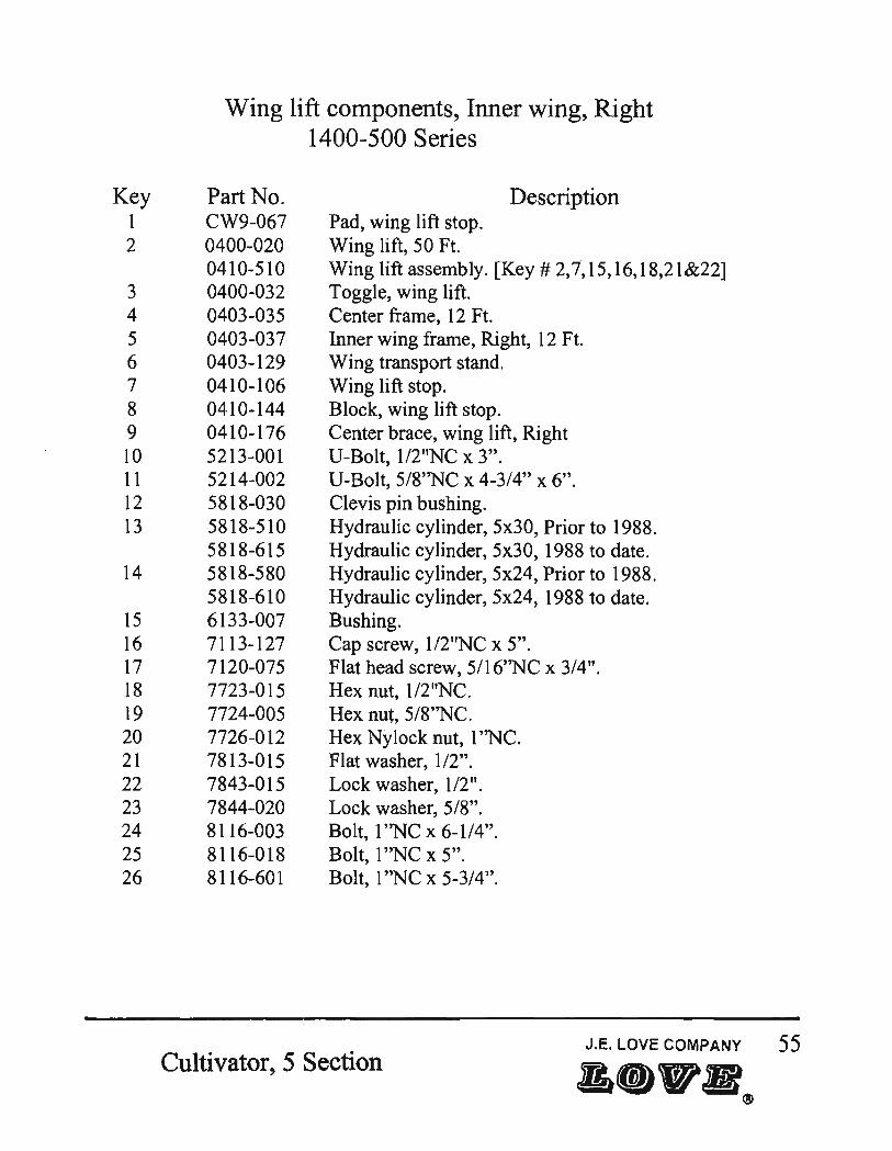
Wing lift components, Inner wing, Left 1400-500 Series
Part No. CW9-067 0400-020 0410-510 0400-032 0403-035 0403-036 0403-129 0410-106 0410-144 0410-175 5213-001 5214-002 5818-030 5818-510 5818-615 5818-580 5818-610 6133-007 7113-127 7120-075 7723-015 7724-005 7726-012 7813-015 7843-015 7844-020 8116-003 8116-018 8116-601
Pad, wing lift stop. Wing lift, 50 Ft.
Description
Wing lift assembly. [Key # 2,7,15,16,18,21&22] Toggle, wing lift. Center frame, 12 Ft. Inner wing frame, Left, 12 Ft. Wing transport stand. Wing lift stop. Block, wing lift stop. Center brace, wing lift, Left. V-Bolt, 1I2"NC x 3". V-Bolt, 5/8"NC x 4-3/4" x 6". Clevis pin bushing. Hydraulic cylinder, 5x30, Prior to 1988. Hydraulic cylinder, 5x30, 1988 to date. Hydraulic cylinder, 5x24, Prior to 1988. Hydraulic cylinder, 5x24, 1988 to date. Bushing. Cap screw, 1I2"NC x 5". Flat head screw, 5/16''NC x 3/4". Hex nut, 1I2"NC. Hex nut, 5/8''NC. Hex Nylock nut, 1 "NC. Flat washer, 1/2". Lock washer, 1/2". Lock washer, 5/8". Bolt, 1 ''NC x 6-114". Bolt, 1 "NC x 5". Bolt, 1 "NC x 5-3/4".
Cultivator, 5 Section J.E. LOVE COMPANY 53
a.1F.~
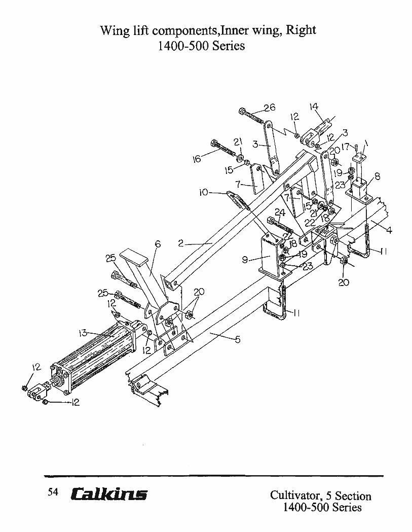
Wing lift components,Inner wing, Right 1400-500 Series
54 Ca.l.ki.n.B Cultivator,5 Section 1400-500 Series
Key 1 2
3 4 5 6 7 8 9 10 11 12 13
14
15 16 17 18 19 20 21 22 23 24 25 26
Wing lift components, Inner wing, Right 1400-500 Series
Part No. CW9-067 0400-020 0410-510 0400-032 0403-035 0403-037 0403-129 0410-106 0410-144 0410-176 5213-001 5214-002 5818-030 5818-510 5818-615 5818-580 5818-610 6133-007 7113-127 7120-075 7723-015 7724-005 7726-012 7813-015 7843-015 7844-020 8116-003 8116-018 8116-601
Pad, wing lift stop. Wing lift, 50 Ft.
Description
Wing lift assembly. [Key # 2,7,15,16,18,21&22] Toggle, wing lift. Center frame, .12 Ft. Inner wing frame, Right, 12 Ft. Wing transport stand. Wing lift stop. Block, wing lift stop. Center brace, wing lift, Right U-Bolt, 1I2"NC x 3". U-Bolt, 5/8''NC x 4-3/4" x 6". Clevis pin bushing. Hydraulic cylinder, 5x30, Prior to 1988. Hydraulic cylinder, 5x30, 1988 to date. Hydraulic cylinder, 5x24, Prior to 1988. Hydraulic cylinder, 5x24, 1988 to date. Bushing. Cap screw, 1I2"NC x 5". Flat head screw, 5116''NC x 3/4". Hex nut, 112 "NC. Hex nut, 5/8''NC. Hex Nylock nut, I"NC. Flat washer, 1/2". Lock washer, 112". Lock washer, 5/8". Bolt, 1 "NC x 6-114". Bolt, 1 "NC x 5". Bolt, 1 ''NC x 5-3/4".
Cultivator, 5 Section J.E. LOVE COMPANY 55
& ••• ®
4
5
Right side
56
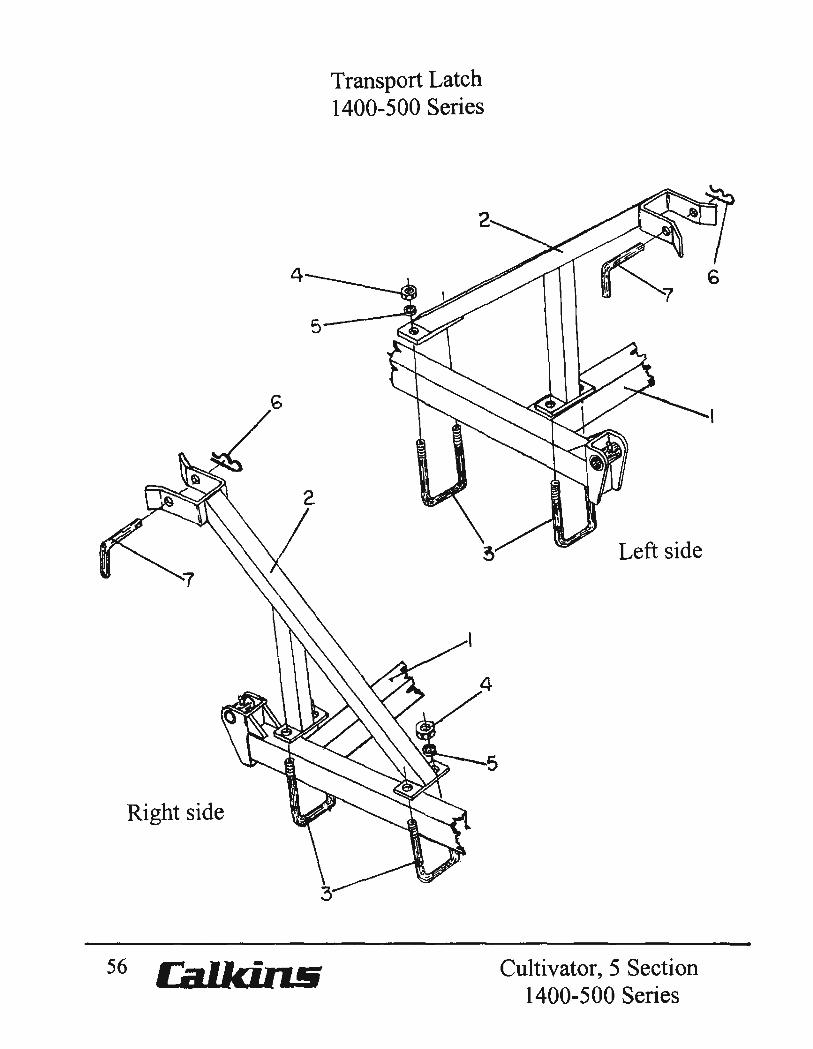
Transport Latch 1400-500 Series
5
Left side
Cultivator, 5 Section 1400-500 Series
Key 1 2 3 4 5 6 7
Part No. 0403-035 0410-082 5214-002 7724-005 7844-020 7920-002 8036-801
Transport Latch 1400-500 Series
Center frame, 12Ft. Transport latch.
Description
U-Bolt, 5/8"NC x 4-3/4" x 6". Hex nut, 5/8"NC. Lock washer, 5/8". Hitch pin, #8. Pin, wing lock.
Cultivator, 5 Section 1400-500 Series
J.E. LOVE COMPANY 57
a ... R®
Wing lift components, Outer wing -left
58 Cal.Ici.ruii Cultivator, 5 Section
Key
1
2 3 4 5 6
7
8 9 10 11 12
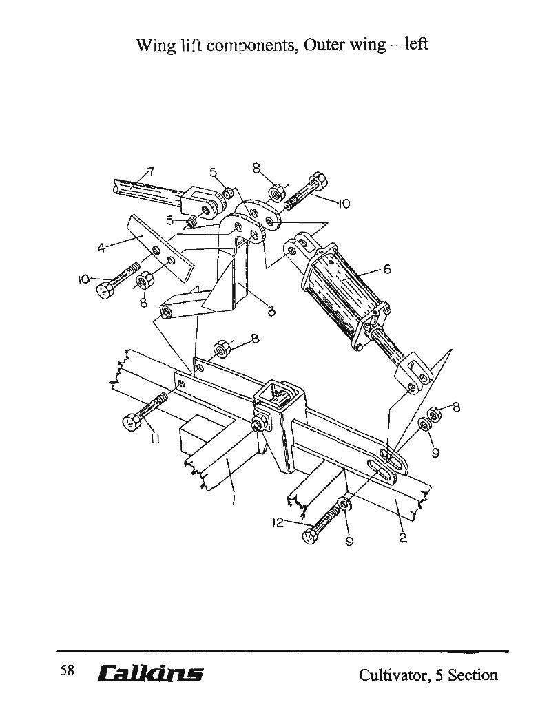
Wing Lift components, Outer wing, Left
Part No.
0403-036 0403-038 0403-040 0410-048 0410-102 5818-030 5818-330 5818-600 5818-510 5818-615 7726-012 7816-020 8116-003 8116-018 8116-601
Description
Inner wing frame, Left, 12Ft. Inner wing frame, Left, 9-1I2Ft. Outer wing frame, Left, 7Ft. Cylinder actuator arm. Support bar. Clevis pin bushing. Hydraulic cylinder, 3x8, Prior to 1988. Hydraulic cylinder, 3x8, 1988 to date. Hydraulic cylinder, 5x30, Prior to 1988. Hydraulic cylinder, 5x30, 1988 to date. Hex Nylock nut, 1·~C. Flat washer, 1". Bolt, 1'~C x 6-1/4", wlNylock nut. Bolt, 1 '~C x 5-5/16", wlNylock nut. Bolt, 1 "Ne x 5-3/4", wlNylock nut.
Cultivator,5 Section J.E. LOVE COMPANY 59
Wing lift components, Outer wing - right
1/ 2
60 Cultivator, 5 Section
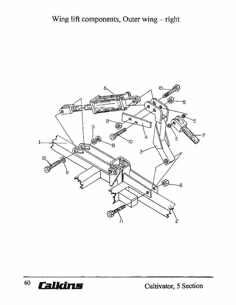
Wing Lift components, Outer wing, Right
Key Part No. Description
I 0403-037 Inner wing frame, Right, 12Ft. 0403-039 Inner wing frame, Right, 9-1/2Ft.
2 0403-041 Outer wing frame, Right, 7Ft. 3 04]0-048 Cylinder actuator ann. 4 0410-102 Support bar. 5 5818-030 Clevis pin bushing. 6 5818-330 Hydraulic cylinder, 3x8, Prior to 1988.
5818-600 Hydraulic cylinder, 3x8, 1988 to date. 7 5818-510 Hydraulic cylinder, 5x30, Prior to 1988.
58]8-615 Hydraulic cylinder, 5x30, 1988 to date. 8 7726-012 Hex Nylock nut, 1 ''NC. 9 7816-020 Flat washer, 1". ]0 8116-003 Bolt, 1 ''NC x 6-1/4", w/Nylock nut. 11 8116-0]8 Bolt, 1''NC x 5-5/16", w/Nylock nut. 12 8116-601 Bolt, 1 ''NC x 5-3/4", w/Nylock nut.
Cultivator, 5 Section J.E. Love COMPANY 61
Hydraulic components, Wing lift center frame
62 ca'kiR61 Cultivator, 5 Section

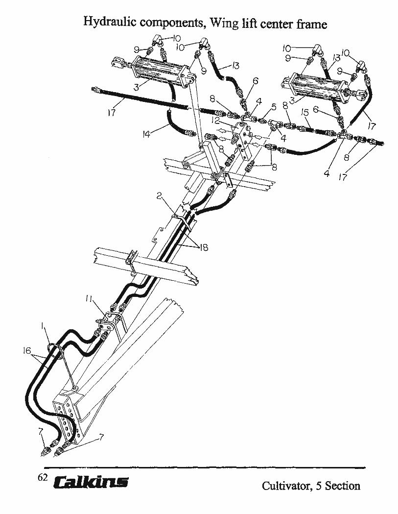
Hydraulic Wing lift components, Center frame
Key Part No. Description
1 0101-037 Hose mast assembly. 2 5229-006 Ty-Rap, compos it tie strap 3 5818-580 Hydraulic cylinder, 5x24 [S512] Prior to 1988.
5818-610 Hydraulic cylinder, 5x24 [AJ-17] 1988 to date. 4 5833-101 Tee, 112" x 112" x 112". 5 5833-110 Hex nipple, 112". 6 5842-602 Line restrictor valve, 1116" orfice, color code green. 7 5843-235 112" Male quick coupler. 8 5843-400 112" Straight swivel union. 9 5845-800 Reducer bushing, 3/4" Male to 112" Female. 10 5846-095 112" 90 degree O-Ring Swivel union. 1 1 5859-050 Cushion valve, color code red side of valve connected
In line to cylinder base. 12 5859-100 Sequence valve assembly. 13 6822-226 3/8" Hose, 1I2"MM, 2Ft-2in. 14 6822-236 3/8" Hose, 1I2"MM, 3 Ft-Oin. 15 6822-262 3/8" Hose, 1I2"MM, 5Ft-2in. 16 6822-272 3/8" Hose, 112" MM, 6Ft.-Oin. 17 6822-280 3/8" Hose, 1/2" MM, 7Ft-8in. [45Ft]
6822-304 3/8" Hose, 112" MM, 10Ft-2in. 18 6822-440 3/8" Hose, 112" MM, 20Ft-Oin. [45Ft]
6822-476 3/8" Hose, 112" MM, 23Ft-Oin. [50Ft]
Cultivator, 5 Section J.E. LOVE COMPANY 63
&.WliI®

Hydraulic components, Wing lift Inner & Outer frames, Left
~--IZ 8
~
4-~
Cultivator,S Section

Hydraulic components, Wing lift Inner & Outer frames, Left
Key Part No. Description
0403-036 Inner wing frame, Left, 12Ft. 0403-038 Inner wing frame, Left, 9-1/2Ft.
2 0403-040 Outer wing frame, Left, 7Ft. 3 0410-048 Cylinder actuator arm. 4 0410-102 Support bar. 5 5818-330 Hydraulic cylinder, 3x8, 1988 and prior.
5818-600 Hydraulic cylinder, 3x8, 1988 to date. 6 5818-510 Hydraulic cylinder, 5x30, 1988 and prior.
5818-615 Hydraulic cylinder, 5x30, 1988 to date. 7 5833-101 Tee, 112' x 112" x 112". 8 5843-400 112" Straight swivel union. 9 5845-800 Reducer bushing, 3/4" Male to 112" Female. 10 5846-092 112" 90 degree O-Ring swivel union, w/1/16" orfice,
[color code red] 1 1 5846-095 112" 90 degree O-Ring swivel union. 12 5859-100 Sequence valve assembly. 13 6822-222 3/8" Hose, 1I2"MM, 22in. 14 6822-230 3/8" Hose, 1I2"MM, 2Ft-6in. 15 6822-274 3/8" Hose, 1I2"MM, 6Ft-II in. 16 6822-280 3/8" Hose, 1I2"MM, 7Ft-8in. 17 6822-304 3/8" Hose, 1I2"MM, 1 OFt-2in. 18 6822-362 3/8" Hose, 1/2"MM, 13Ft-6in. 19 6822-395 3/8" Hose, 1I2"MM, 16Ft-Oin.
Cultivator,S Section J.E. LOVE COMPANY 65
&.WB~
Hydraulic components, Wing lift Inner & Outer frames, Right
12'----===+-
66 Ca.'IdR!l Cultivator, 5 Section
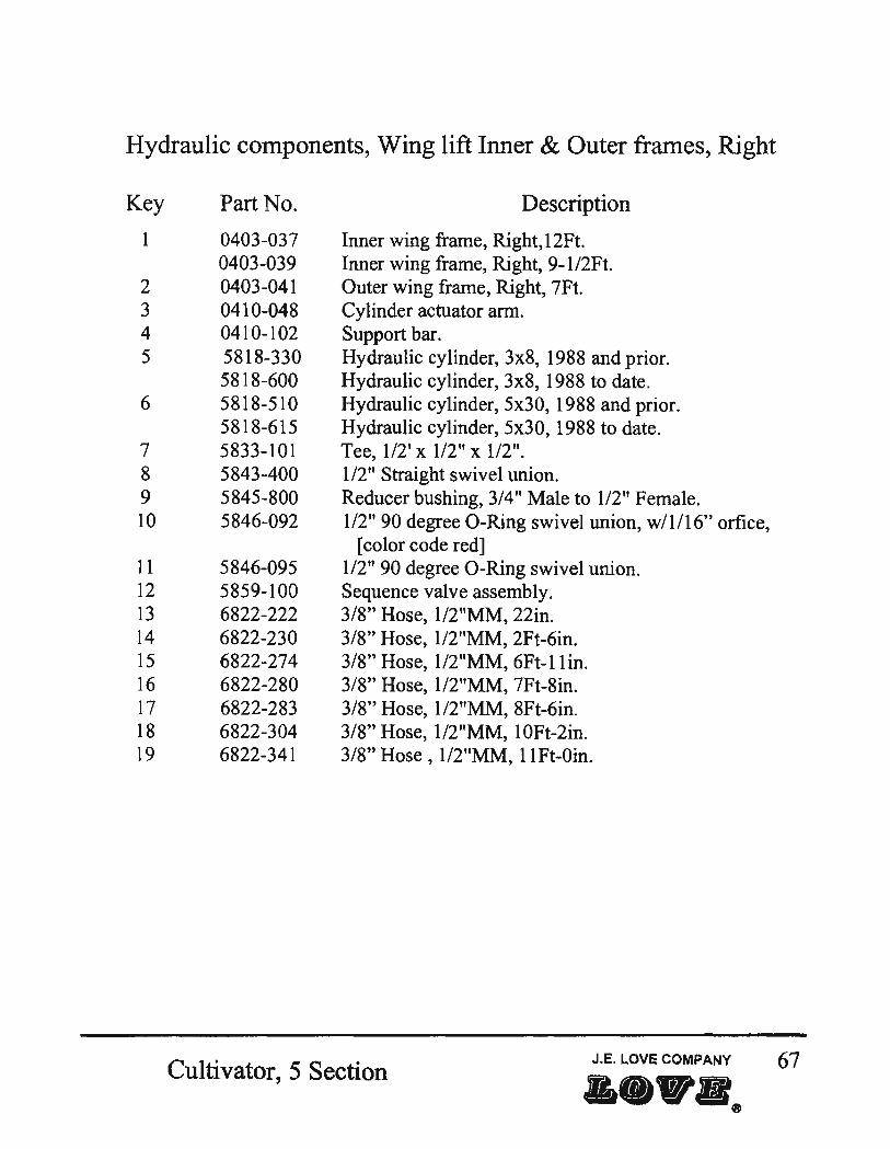
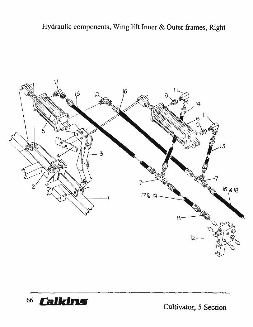
Hydraulic components, Wing lift Inner & Outer frames, Right
Key Part No. Description
1 0403-037 Inner wing frame, Right, 12Ft. 0403-039 Inner wing frame, Right, 9-1I2Ft.
2 0403-041 Outer wing frame, Right, 7Ft. 3 0410-048 Cylinder actuator arm. 4 0410-102 Support bar. 5 5818-330 Hydraulic cylinder, 3x8, 1988 and prior.
5818-600 Hydraulic cylinder, 3x8, 1988 to date. 6 5818-510 Hydraulic cylinder, 5x30, 1988 and prior.
5818-615 Hydraulic cylinder, 5x30, 1988 to date. 7 5833-101 Tee, 112' x 112" x 112". 8 5843-400 1/2" Straight swivel union. 9 5845-800 Reducer bushing, 3/4" Male to 112" Female. 10 5846-092 112" 90 degree O-Ring swivel union, w/1/16" orfice,
[color code red] 11 5846-095 112" 90 degree O-Ring swivel union. 12 5859-100 Sequence valve assembly. 13 6822-222 3/8" Hose, 1I2"MM, 22in. 14 6822-230 3/8" Hose, 1I2"MM, 2Ft-6in. 15 6822-274 3/8" Hose, 1I2"MM, 6Ft-11in. 16 6822-280 3/8" Hose, 1I2"MM, 7Ft-8in. 17 6822-283 3/8" Hose, 1I2"MM, 8Ft-6in. 18 6822-304 3/8" Hose, 1I2"MM, 1 OFt-2in. 19 6822-341 3/8" Hose, 1I2"MM, 11Ft-Oin.
Cultivator, 5 Section J.E. LOVE COMPANY 67
····8

68 Callcirui
Fixed Shank Assembly
2
22
®- 18 I
21
7
Cultivator, 5 Section

Fixed Shank Assembly
Key Part No. Description
1 0201-062 Shank mount yoke. 2 0400-038 Spring mount. 3 0400-550 Fixed shank assembly. 4 5123-002 Shank spring. 5 5939-003 Shank. 6 5949-012 Point, Reversable bolt-on. 7 5952-625 Sweep blade, 114" x 9". 8 6123-002 Spring with inserts, assembly. 9 6919-050 Top insert. 10 6919-052 Bottom insert. 11 7113-119 Tap bolt, 1/2''NC x 3-112" Full thread. 12 7113-121 Cap screw, 1I2"NC x 3-3/4". 13 7113-129 Cap screw, 1/2"NC x 5-112". 14 7114-109 Cap screw, 5/8''NC x 2". 15 7115-067 Cap screw, 3/4"NF x 5". 16 7272-058 No.3 Plow bolt, 7/16''NC x 1-112". 17 7722-015 Hex nut, 7/16''NC. 18 7723-015 Hex nut, 112 "NC. 19 7723-216 Hex lock nut,1I2NC. 20 7724-005 Hex nut, 5/8''NC. 21 7725-122 Hex lock nut, 3/411NF. 22 7843-015 Lock washer, 1/2". 23 7844-020 Lock washer, 5/8".
Cultivator, 5 Section J.E. LOVE COMPANY 69

Q e: < ~ g '" U"I
00 (1) a _. g
Cultivator Shank Layout
9 in. Shank spacing -......J o I 88--;;~I2< --.~-
.-7; 72 ~ 70
79
.. 1 ~J . &J ---- r-1 ---'3 - .. --..1. I
f----.~ '5 I J' __ .. 1 I I---- 27 27 ---I I- 7
1--_______ 7• -I
1------- ~~ -I
F,29-70-I- II
111"""'- T r 1T I 11'\ r • r Tr' T'\~
J):(l I I If
i ~II fir : I -<~ i ~ I i~---ff • R _ ~ ~ ~ 1 ~S.
llil :::I. [ II 1 u IiII " " fIJ-- 'I •
! J J!_ e- \ !"\~ ! I 1 j I I l ~ ~ I II I 1 It-~, 7/ ~ '~ , ~"
: d ~ III ~ \\ ~ P: I ~ . ~ J. ~ p
I T I I
1 I .! I \ .!. • • ~ L, I .' 'I .' l.IlI. • I. II IIlll ___ • - __ .1 illIL-
T -- :- ,I '-I , I r !
LL 18 18 E',6J_J J6 36 --~2----I
~.- 61------1 1~ .74. 98 -------l
~-----------I~------------------~ ~----------I~----------~
-0-2 1---.}II ----I ~---47---~ f-----56----~ j---~---aJ------_____+
7Ft. Outer wing frame. 12Ft Center frame ~-----------------------14a------------------------1
12Ft Inner wing frame.

Cultivator Shank Layout
r----H U I ~ "M __ '1_~z_e -----,
~~~~~4 V2--2~ ,~~/:~ .~~ ~9 7~ 10 1/2- - 28 21
I 3 1/2 - r- 21 14
! j) i (i i r~ '\P"" 1,1 ~\' ! ! j h 1..! \ Itll! '\. '\. _ e-- ~ ! ! '- I I r : ~ ~! '\ ! L- r1 ! ~b J! _~ cI ! ~~ ~~! S T .I! It i \\1":1:· l' ~"~ · r- i
, 10 1/2- I I' , 111 J I !
I ~) II \ I ~ '\. ! d
t, I ' ~ -1n ! ~ ~ I ; i I I r--i~! ~~~ := I \ r 'Q ". ~ I" I
I I ! ,
........,...-;I----t-... I I d n-Il :
[!] , ! [!] , ~ 1/~- l- ! - -7 - "-7
- 17 1/2-'1-17 I/Z ~ I -14- I---Z8-
-31 1/2 31 1/2-: 42 -J5- I ~38 1/2 38 1/2- 49 42--------'
'----59 1/2 59 '/2 70 !Ki------.I
~---74 74 77 63----'
IDS 8£------1
1--------112-----------'
12Ft. Center frame 'J~._ 7Ft. Outer wing frame.
12Ft Inner wing frame.
...... r--
§ . .0 () o
\I)
\I')
....... o ~ > .-~ 8
n ~ -r-+ ,.... <: a o
",I-i
VI
r/J CD (j r-+ ,.... o o
.....,J N
I I
I I
III I
I I
I I
I I
1ll\J I
I I
IJ
66 66
52 1/2 52 1/2
~4S 1/2 451/2-
r-24 1/2--241/2-10 1/2- .-3 1/2- r-
I
1/! (
16 • I \ ..
~I I I
'--~ ::1._
r : \ 16 I ~ d. I
:I :L • If I
1\ ~ .
I 10j,- I
I
'\
" \
I
I, t ~ \ t-- \ '----i J-- ~
J I . I I
[!J ! [!J
~ 1/2 l LJ -" '1>-'-" 'I> ~ I....-Jl 1/2 31 1/2-
38 1/2 J8 1/2-
~In ~ln
74 74
12Ft. Center frame
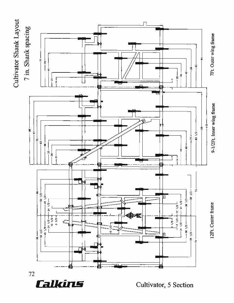
Cultivator Shank Layout
118 7 in. Shank spacing
91 70
6J
~n 56 70 ;---J5- 49 -1---28- 21
f--21- 14 I I
I I I I
J]if\ I I I
I I I I
I "- IL-
.~ I .\ I
I .\ jb I I I
UIlI ri lB.1 I
~ • I
I I I .
I i d \ \
~ I
~ I I
,=:~ I
----1 I ~ ~ I C D • . I . ,
d [I .,. II
I I
'-7 - '-7
,..-14- f---28-42 1---.35-
49 42
77 56
8J 1/2 63
lOS 84
~--------------------112 J
9-1/2Ft. Inner wing frame 7Ft. Outer wing frame

This page intentionally left blank
13
;, FRONT
."
Wing Extension Components 2, 4 & 6 Shanks
2
74 CalldlU6 Cultivator, 5 Section

Key
1
2 3 4 5 6 7
6 Shank Extension
:3
~ FRONT
't
45 & 50 FT.
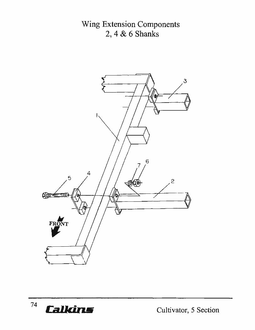
Wing Extension Components 2, 4 & 6 Shanks
Part No. Description
0403-040 Outer wing frame, Left. 7 FT. 0403-041 Outer wing frame, Right, 7 FT. 0403-093 Shank extension, 22" 0403-094 Shank extension, 13" 0410-079 Base plate 7114-055 Cap screw, 5/8"NC x 5-112" 7724-005 Hex nut, 5/8''NC 7844-020 Lock washer, 5/8"
4 Shank 2 Shank Extension
~ Extension
r r 4Yi' 4Yi'
57
~ FRONT
2 't
45 & 50 FT. 45 & 50 FT.
J.E. LOVE COMPANY 75 a_._~ Cultivator, 5 Section
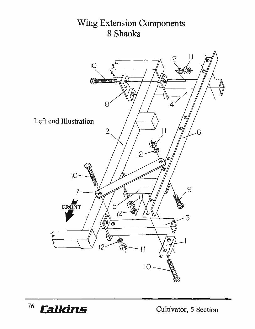
Wing Extension Components 8 Shanks
Left end Illustration
10-\ 7---L.~
• FRONT ,
76 Ca1lc.i.n&
8
Cultivator, 5 Section

Wing Extension Components 8 Shanks
Key Part No.
1 0206-031 2 0403-040
0403-041 3 0403-090 4 0403-093 5 0403-094 6 0403-295
0403-298 7 0403-299 8 0410-079 9 7114-003 10 7114-055 11 7724-005 12 7844-020
Description
Clamp plate, 4-3/4" span, V-Formed Outer wing frame, Left, 7 FT. Outer wing franle, Right, 7 FT. Shank extension, 26". Shank extension, 22". Shank extension, 13". Shank mount support, Right. Shank mount support, Left Shank extension brace. Base plate. Cap screw, 5/8''NC x 1-114". Cap screw, 5/8''NC x 5-112". Hex nut, 5/8''NC. Lockwasher, 5/8".
Cultivator,5 Section J.E. LOVE COMPANY 77
78
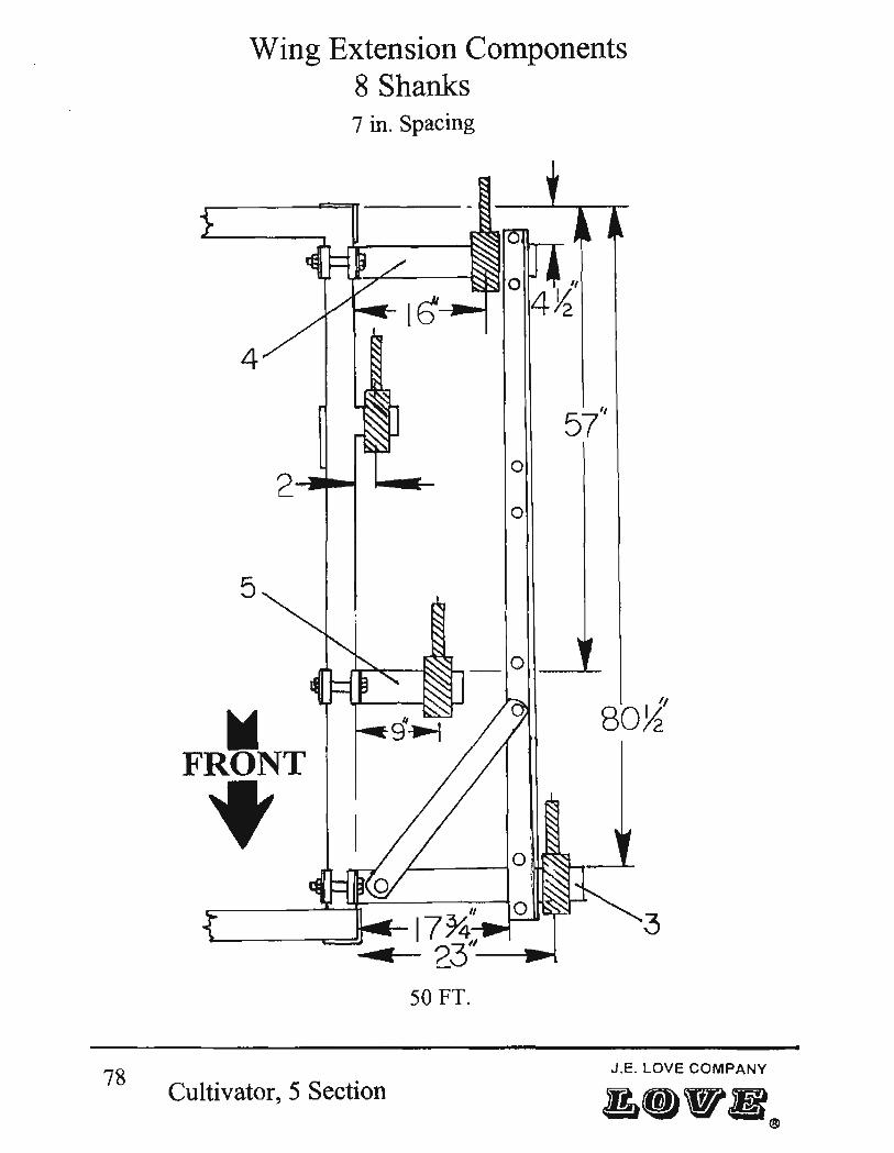
Wing Extension Components 8 Shanks 7 in. Spacing
4
o
o
5
o _..L-
~ '/
80%
FRONT
" L---_------w=-~w..--- 17 ~ • 23"-~
3
50FT.
J .E. LOVE COMPANY
Cultivator, 5 Section

Wing Extension Components 8 Shanks
7 in. Spacing
Key Part No. Description
3 0403-090 4 0403-093 5 0403-094
Shank extension, 26". Shank extension, 22". Shank extension, 13".
Cultivator, 5 Section 79
80
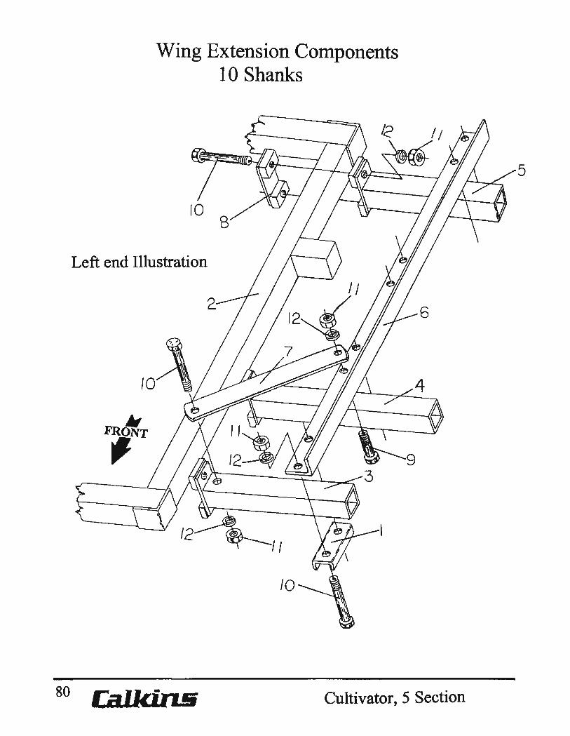
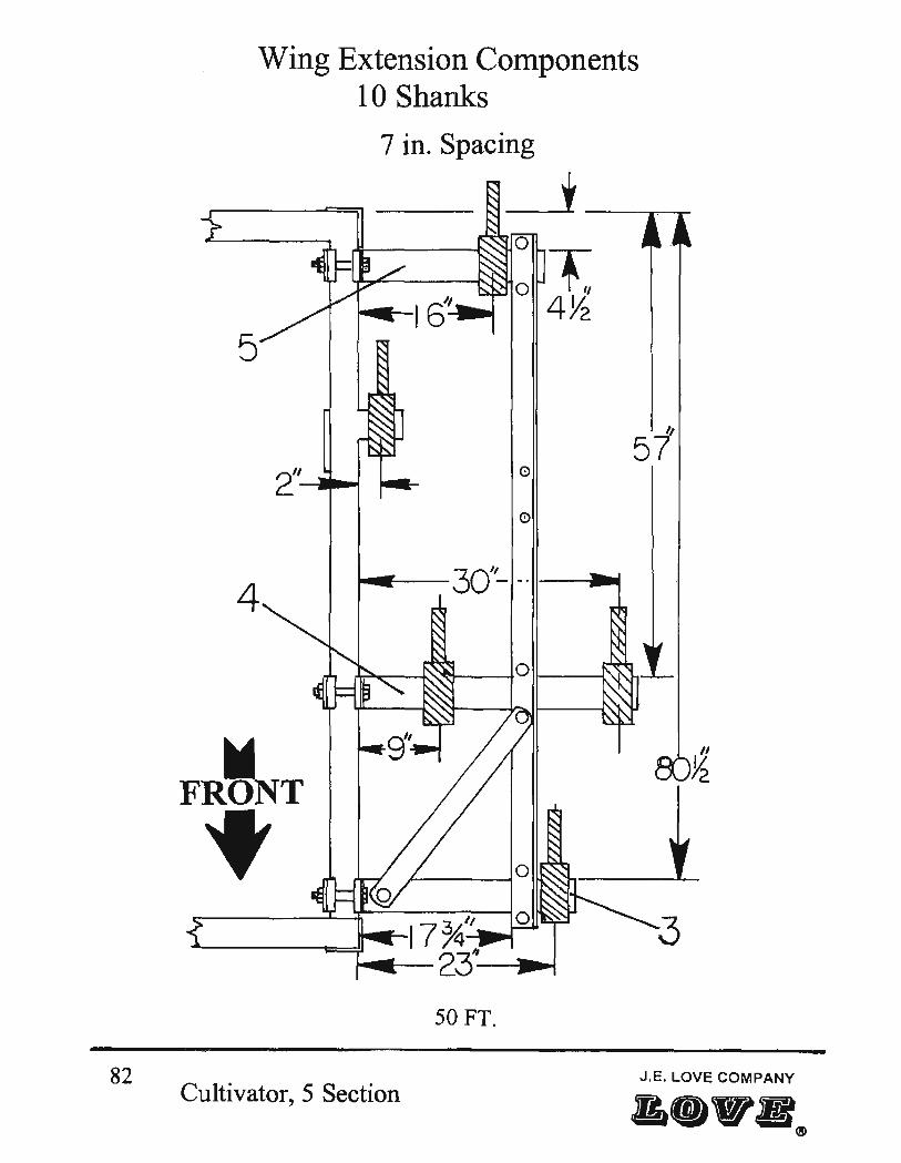
Wing Extension Components 10 Shanks
Left end Illustration
II FRONT ,
Cultivator, 5 Section
5
Key
1 2
3 4 5 6
7 8 9 10 11 12
Wing Extension Components 10 Shanks
Part No. Description
0206-031 Clamp plate, 4-3/4" span, V-Formed. 0403-040 Outer wing frame, Left, 7 FT. 0403-041 Outer wing frame, Right, 7 FT. 0403-090 Shank extension, 26". 0403-092 Shank extension, 33". 0403-093 Shank extension, 22". 0403-295 Shank mount support, Right. 0403-298 Shank mount support, Left. 0403-299 Shank extension brace. 0410-079 Base plate. 7114-003 Cap screw, 5/8"NC x 1-1/4". 7114-055 Cap screw, 5/8"NC x 5-1/2". 7724-005 Hex nut, 5/8''NC. 7844-020 Lockwasher, 5/8".
Cultivator, 5 Section J.E. lOVE COMPANY 81
"48 WI_ e
82
Wing Extension Components 10 Shanks
7 in. Spacing
---'~ o
ot 4~
5
II
57 o
o
4
~ FRONT
~17~'1 0 3 ~----~~ 2~--~
50FT.
/1
~
Cultivator, 5 Section J.E. LOVE COMPANY
Key
3 4 5
Wing Extension Components 10 Shanks
Part No.
0403-090 0403-092 0403-093
Description
Shank extension, 26". Shank extension, 33". Shank extension, 22".
Cultivator, 5 Section 83

• FRONT
"
9
Wing Extension Components 12 & 14 Shanks
Left end Illustration
84 Cal.lcirui Cultivator, 5 Section

Key
1 2
3 4 5 6 7
8 9 10 11 12 13
Wing Extension Components 12 & 14 Shanks
Part No. Description
0206-031 Clamp plate, 4-3/4" span, V-Formed 0403-040 Outer wing frame, Left, 7 FT. 0403-041 Outer wing frame, Right, 7 FT. 0403-090 Shank extension, 26". 0403-091 Shank extension, 40". 0403-092 Shank extension, 33". 0403-095 Shank extension, 46". 0403-295 Shank mount support, Right. 0403-298 Shank mount support, Left. 0403-299 Shank extension brace. 0410-079 Base plate. 7114-003 Cap screw, 5/8''NC x 1-1/4". 7114-055 Cap screw, 5/S''NC x 5-1/2". 7724-005 Hex nut, 5/S''NC. 7S44-020 Lockwasher, 5/S".
Cultivator, 5 Section J.E. LOVE COMPANY 85
••• B e
~
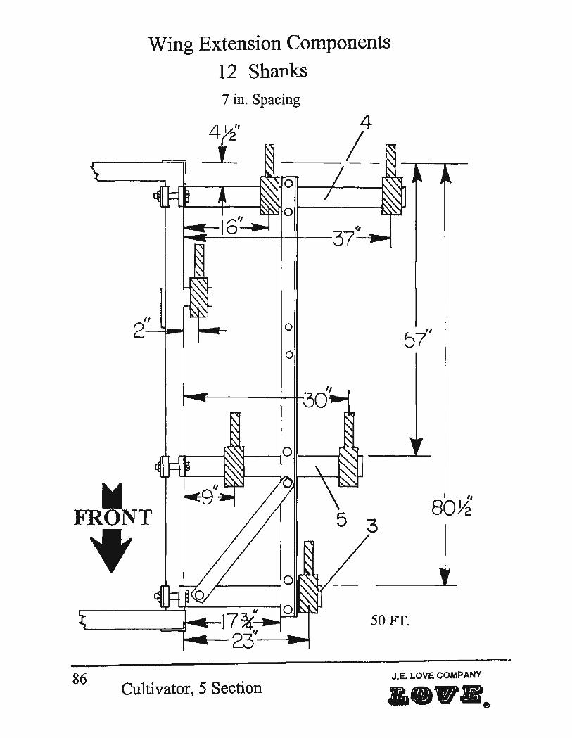
Wing Extension Components
12 Shanks 7 in. Spacing
4 1 '1 ).2
I °11---1-_----1\
II
2----Y1.-t o
o
FRONT II
80}2
Wing Extension Components 12 & 14 Shanks
Key Part No.
3 0403-090 4 0403-091 5 0403-092 6 0403-095
Description
Shank extension, 26". Shank extension, 40". Shank extension, 33". Shank extension, 46".
Cultivator,5 Section 87

~ FRONT
Wing Extension Components
14 Shanks 7 in. Spacing
"Ir----4..' 'V----IO ~----t:
3
50FT.
J.E. LOVE COMPANY 88 . CultIvator, 5 Section

WUlg Extension Components 12 & 14 Shanks
Key Part No.
3 0403-090 4 0403-091 5 0403-092 6 0403-095
Description
Shank extension, 26". Shank extension, 40". Shank extension, 33". Shank extension, 46".
Cultivator, 5 Section 89
• FRONT
"
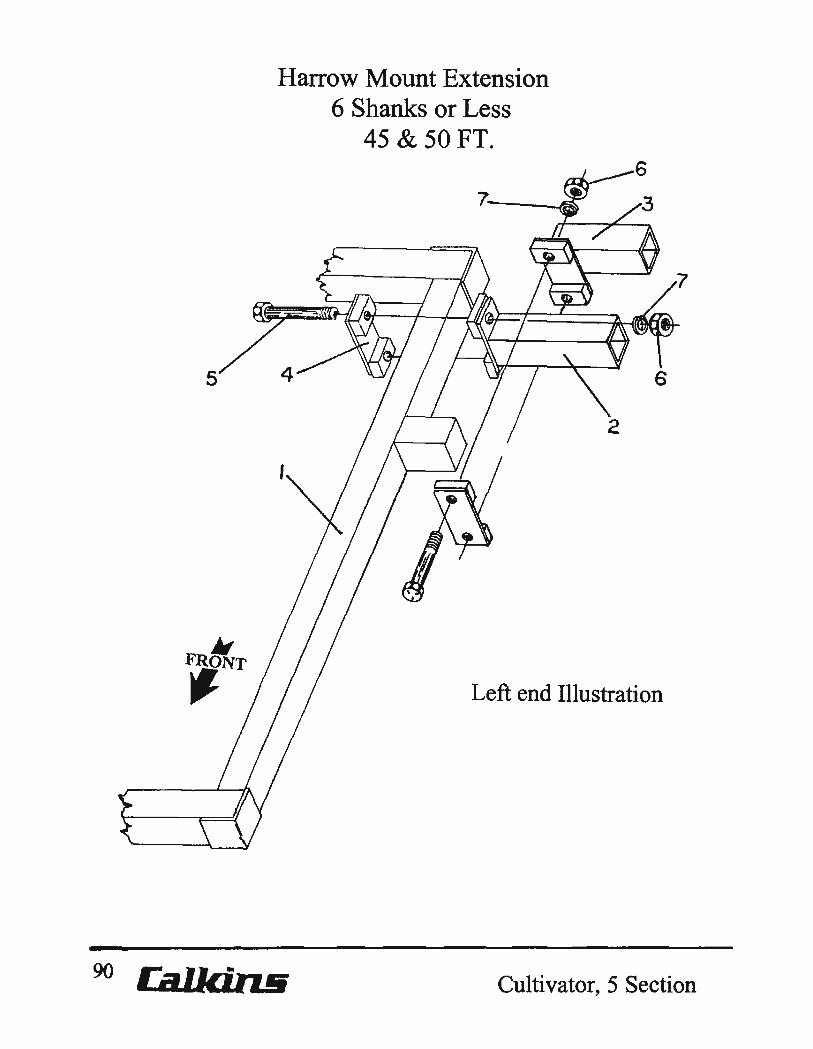
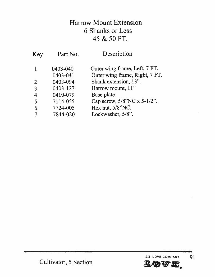
Harrow Mount Extension 6 Shanks or Less
45 & 50 FT.
7-_~
6
Left end Illustration
Cultivator, 5 Section
Key
1
2 3 4 5 6 7
Harrow Mount Extension 6 Shanks or Less
45 & 50 FT.
Part No. Description
0403-040 Outer wing frame, Left, 7 FT. 0403-041 Outer wing frame, Right, 7 FT. 0403-094 Shank extension, 13". 0403-127 Harrow mount, 11" 0410-079 Base plate. 7114-055 Cap screw, 5/8''NC x 5-112". 7724-005 Hex nut, 5/8''NC. 7844-020 Lockwasher, 5/8".
J.E. LOVE COMPANY 91 Cultivator, 5 Section a.".®

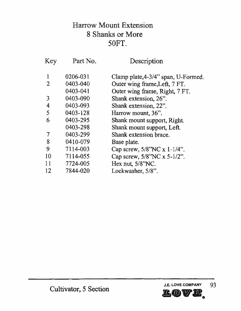
Harrow Mount Extension 8 Shanks or More
50FT. \ I
Left side Illustration
10
12~11
12
92 caJkin.Iii Cultivator, 5 Section
Key
1 2
3 4 5 6
7 8 9 10 11 12
Harrow Mount Extension 8 Shanks or More
50FT.
Part No. Description
0206-031 Clamp plate,4-3/4" span, V-Formed. 0403-040 Outer wing frame,Left, 7 FT. 0403-041 Outer wing frame, Right, 7 FT. 0403-090 Shank extension, 26". 0403-093 Shank extension, 22". 0403-128 Harrow mount, 36". 0403-295 Shank mount support, Right. 0403-298 Shank mount support, Left. 0403-299 Shank extension brace. 0410-079 Base plate. 7114-003 Cap screw, 5/8''NC x 1-1/4". 7114-055 Cap screw, 5/8''NC x 5-1/2". 7724-005 Hex nut, 5/8''NC. 7844-020 Lockwasher, 5/8".
Cultivator, 5 Section J.E. LOVE COMPANY 93
a ••• ~

Part No.
CW9-030 CW9-031 CW9-034 CW9-045 CW9-067
CW9-555 CW9-556
0101-037 0106-211 0200-147 0201-062 0201-065 0206-031 0216-058
0400-020 0400-025 0400-032 0400-038 0400-040 0400-041 0400-048 0400-049 0400-050 0400-051 0400-059 0400-062 0400-063 0400-065 0400-082 0400-083 0400-084 0400-085 0400-087
A-I
Part number page reference
Description
Caster wheel leg, Left. Caster wheel leg, Right Spindle platfonn Shaft, 1-5/8" x 18". Pad, wing lift stop.
Caster wheel leg assembly, Left Caster wheel leg assembly, Right
Hydraulic hose mast assembly Hydraulic hose mast Limit plate Shank mount, yoke Rear stand, 42-1/2". Clamp plate, 4" Span, U-Fonned Mount plate
Page No.
17 19
17,19 17,19
47,53,55
17 19
7,41,63 7
17,19 69 7
7,17,19,77,81,85,93 9, II
Wing lift, 50Ft. 47,49,53,55 Pivot ann 21,23,25,27,29,31,33,39 Toggle, wing lift 47,49,53,55 Spring mount 69 Center frame walking beam, W 10 hubs & spindles, Left 21,25 Center frame walking beam, right, W 15419-122 Races 23,25,31 Tandem wheel leg, W/O spindle, Inner wing, Left 35,37 Tandem wheel leg, W/O Spindle,Inner wing, Right 35,37 Walking beam assembly, Inner wing, Left 35,37 Walking beam assembly, Inner wing, Right 35,37 Center support bar 45 Rear stand adjustment bracket 7 Transport latch, 45Ft. 51 Shank mount "T" type, prior to 1998 9 Forward shank mount, Center frame 7 Forward shank mount, Wing frames 9-1I2Ft. 9,11 Forward shank mount, Wing frames 12Ft. 9,11 8" 90 degree bolt on shank mount 7 Forward shank mount, 66in ,Outer wings 13,15
Cultivator, 5 Section
Part No.
0400-548 0400-549 0400-550 0400-551 0400-552
0400-955
0403-004 0403-005
0403-020 0403-035 0403-036 0403-037 0403-038 0403-040 0403-041
0403-050 0403-051 0403-052 0403-053
0403-063 0403-064 0403-065
0403-090 0403-091 0403-092 0403-093 0403-094 0403-095
0403-125 0403-126 0403-127 0403-128 0403-129
Description Page No.
Wheel leg assembly, W Iwalking beam & 6 bolt hubs, Left Wbeelleg assembly, W/walking beam & 6 bolt hubs, Right Fixed shank assembly
29,35 27,35 69
35,37 35,37
Walking beam frame only, Inner wing, Left Walking beam frame only, Inner wing, Right
Mount plate
Tongue, Right side Tongue, Left side
7
5,7 5,7
Cross tongue Center frame [CF] Inner wing frame, Left, 12Ft. Inner wing frame, Right, 12Ft. Inner wing frame, Left, 9-1I2Ft. Outer wing frame, Left, 7Ft. Outer wing frame, Right, 7Ft.
5,7 5,7,21,23,45,47,49,55,57
5,29,47,51,53,59,65 5,11,27,49,51,55,61,63,67
5 ,29,47,51,59,65 5,13,33,59,65,75,77,81,85,91,93 5,15,61,67,75,77,81,85,91,93
Tandem wheel leg, WIG spindle, Inner wing, Left Tandem wheel leg, W 10 spindle, Inner wing, Right Center frame wheel leg, Left, WIG spindle
35,37 35,37 21,25 23,25 Center frame wheel leg, Right, W 10 spindle
Walking beam frame only, Outer wing, Left Walking beam frame only, Outer wing, Right Wing lift, 45Ft.
Shank extension, 26 in Shank extension, 40 in Shank extension, 33 in Shank extension, 22 in Shank extension, 13 in Shank extension, 46 in
Wing transport stand, 45Ft. Cylinder actuator arm stop, 45Ft. Harrow mount, 11 in Harrow mount, 36 in Wing transport stand, 50Ft.
Cultivator, 5 Section
35,37 35,37 47,49
77,79,81,83,85,87,89,93 85,87,89
81,83,85,87 75,77,79,81,83,93
75,77,79,91 85,87,89
51 47,49 91 93
51,53,55
A-2
Part No.
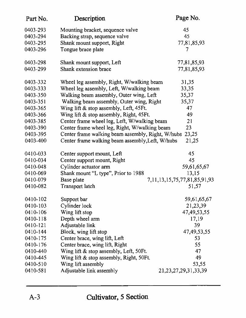
0403-293 0403-294 0403-295 0403-296
0403-298 0403-299
0403-332 0403-333 0403-350 0403-351 0403-365 0403-366 0403-385 0403-390 0403-395 0403-400
0410-033 0410-034 0410-048 0410-069 0410-079 0410-082
0410-102 0410-103 0410-106 0410-118 0410-121 0410-144 0410-175 0410-176 0410-440 0410-445 0410-510 0410-581
A-3
Description
Mounting bracket, sequence valve Backing strap, sequence valve Shank mount support, Right Tongue brace plate
Shank mount support, Left Shank extension brace
Page No.
45 45
77,81,85,93 7
77,81,85,93 77,81,85,93
Wheel leg assembly, Right, W/walking beam 31,35 Wheel leg assembly, Left, W/walking beam 33,35 Walking beam assembly, Outer wing, Left 35,37 Walking beam assembly, Outer wing, Right 35,37 Wing lift & stop assembly, Left, 45Ft. 47 Wing lift & stop assembly, Right, 45Ft. 49 Center frame wheel leg, Left, W /walking beam 21 Center frame wheel leg, Right, W /walking beam 23 Center frame walking beam assembly, Right, W/hubs 23,25 Center frame walking beam assembly,Left, W /hubs 21,25
Center support mount, Left Center support mount, Right Cylinder actuator arm Shank mount "L type", Prior to 1988 Base plate Transport latch
Support bar Cylinder lock Wing lift stop Depth wheel arm Adjustable link Block, wing lift stop Center brace, wing lift, Left Center brace, wing lift, Right
45 45
59,61,65,67 13,15
7,11,13,15,75,77,81,85,91,93 51,57
59,61,65,67 21,23,39
47,49,53,55 17,19
39 47,49,53,55
53 55
Wing lift & stop assembly, Left, 50Ft. Wing lift & stop assembly, Right, 50Ft. Wing lift assembly
47 49
53,55 21,23,27,29,31,33,39 Adjustable link assembly
Cultivator,5 Section

Part No. Description Page No.
5123-002 Shank spring 69 5213-001 V-Bolt, 1I2"NC x 3" 53,55 5214-002 V-Bolt, 5/8''NC x 4-3/4" x 6" 45,47,49,51,53,55,57 5229-006 Ty-Rap, composit tie strap 41,63
5419-113 Outer bearing 17,37 5419-118 Outer cup 17,37 5419-122 Race 25 5419-125 Cup, bearing race 37 5419-126 Bearing 37 5419-127 Bearing 37 5419-141 Cup, inner 17,37 5419-142 Bearing cone, inner 17,37 5419-152 Bearing 25 5419-153 Race 25 5419-154 Bearing 25
5439-020 Seal, wheel leg assembly 37 5439-141 Seal 17,37 5439-151 Seal 25 5619-021 Hub assembly, 6 bolt 17,19 5619-022 Hub, 6 bolt 17 5619-025 8 bolt hub assembly 25 5619-026 Hub, 8 bolt 25
5629-001 Spindle, 3650, 2-1/8" butt 37 5639-026 Mounted tire, 7.60 x 15,6 ply, Outer wing 35 5639-029 Tire & wheel, 7.60 x 15, 8 ply 17,19 5639-421 Wheel, 15 x 6H, F/6, 6 bolt hub 19,35 5639-426 Wheel, 15 x 8, 8 bolt 23 5639-583 Mounted tire, 9.5L x 15, 6 ply, Ribbed, Outer wing 35 5639-584 Tire mounted, 5639-426 wheel W /5649-062 tire 23 5639-588 Mounted tire, IlL x 15,6 ply, ribbed, inner wing 35 5639-589 Tire mounted, 5639-426 wheel W /5649-503 tire 23
5649-009 Tire, 7.60 x 15,6 ply Rib Impl 17,35 5649-060 Tire, 9.5L x 15,6 ply Rib Impl 35 5649-062 Tire, 9.5L x 15, 8 ply, Rib Impl 23 5649-503 Tire, 11 Lx 15, 8 ply, Rib Impl 23 5649-504 Tire, IlL x 15,6 ply, Rib Impl 35
Cultivator, 5 Section A-4
Part No.
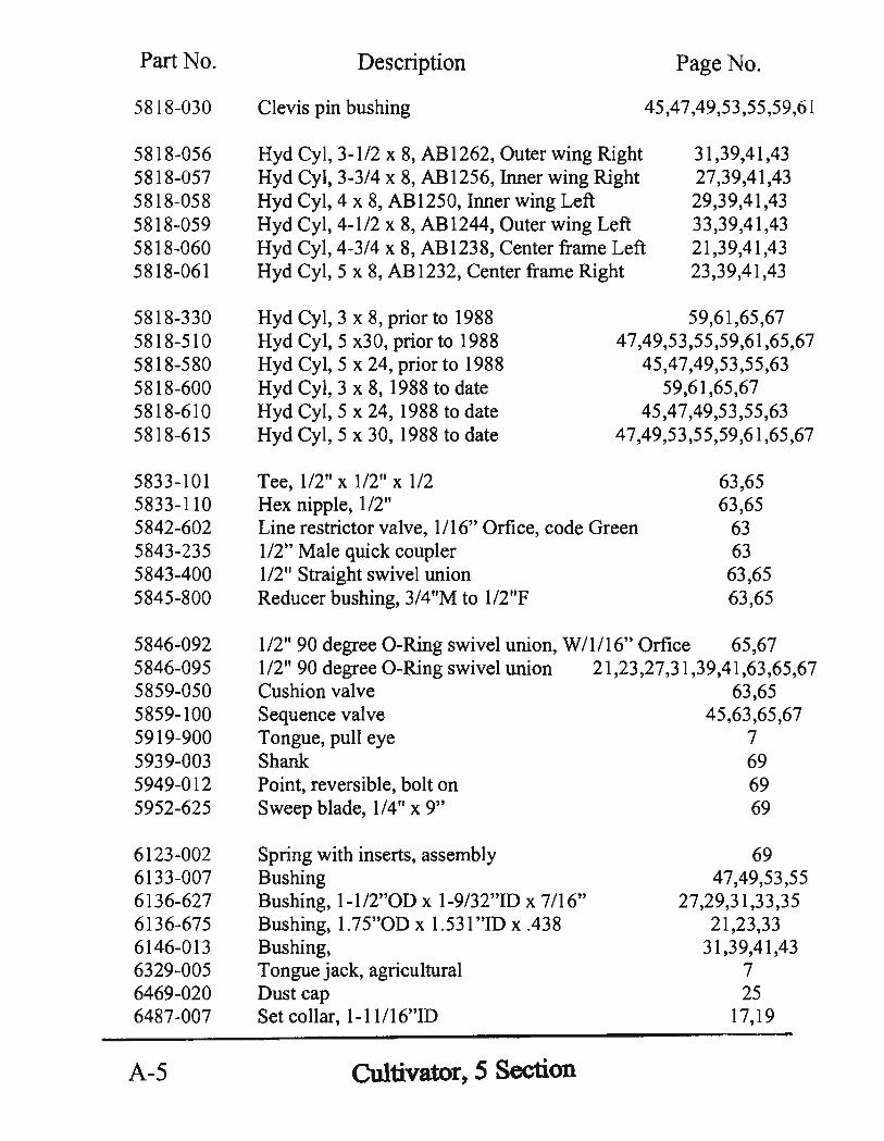
5818-030
5818-056 5818-057 5818-058 5818-059 5818-060 5818-061
5818-330 5818-510 5818-580 5818-600 5818-610 5818-615
5833-101 5833-110 5842-602 5843-235 5843-400 5845-800
5846-092 5846-095 5859-050 5859-100 5919-900 5939-003 5949-012 5952-625
6123-002 6133-007 6136-627 6136-675 6146-013 6329-005 6469-020 6487-007
A-5
Description
Clevis pin bushing
Page No.
45,47,49,53,55,59,6 i
Hyd Cyl, 3-112 x 8, AB1262, Outer wing Right Hyd Cyl, 3-3/4 x 8, AB 1256, Inner wing Right Hyd Cyl, 4 x 8, AB1250, Inner wing Left
31,39,41,43 27,39,41,43 29,39,41,43 33,39,41,43 21,39,41,43 23,39,41,43
Hyd Cyl, 4-112 x 8, ABI244, Outer wing Left Hyd Cyl, 4-3/4 x 8, AB1238, Center frame Left Hyd Cyl, 5 x 8, AB1232, Center frame Right
Hyd Cyl, 3 x 8, prior to 1988 Hyd Cyl, 5 x30, prior to 1988 Hyd Cyl, 5 x 24, prior to 1988 Hyd Cyl, 3 x 8, 1988 to date Hyd Cyl, 5 x 24, 1988 to date Hyd Cyl, 5 x 30, 1988 to date
Tee 112" x 112" x 112 , Hex nipple, 112"
59,61,65,67 47,49,53,55,59,61,65,67
45,47,49,53,55,63 59,61,65,67
45,47,49,53,55,63 47,49,53,55,59,61,65,67
Line restrictor valve, 1/16" Orfice, code Green 1/2" Male quick coupler
63,65 63,65
63 63 63,65 1/2" Straight swivel union
Reducer bushing, 3/4"M to 1I2"F 63,65
112" 90 degree O-Ring swivel union, W/1/16" Orfice 65,67 112" 90 degree O-Ring swivel union 21,23,27,31,39,41,63,65,67 Cushion valve 63,65 Sequence valve 45,63,65,67 Tongue, pull eye 7 Shank 69 Point, reversible, bolt on 69 Sweep blade, 1/4" x 9" 69
Spring with inserts, assembly Bushing Bushing, l-lI2"On x 1-9/32"ID x 7/16" Bushing, 1.75"OD x 1.531 "ID x .438 Bushing, Tongue jack, agricultural Dust cap Set collar, 1-11/16"ID
Cultivator, 5 Section
69 47,49,53,55
27,29,31,33,35 21,23,33
31,39,41,43 7 25
17,19
Part No. Description Page No.
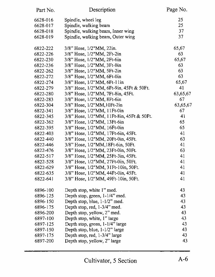
6628-016 Spindle, wheel leg 25 6628-017 Spindle, walking beam 25 6628-018 Spindle, walking beam, Inner wing 37 6628-019 Spindle, walking beam, Outer wing 37
6822-222 3/8" Hose, 1/2"MM, 22in. 65,67 6822-226 3/8" Hose, 1I2"MM, 2Ft-2in 63 6822-230 3/8" Hose, 1/2 "MM, 2Ft-6in 65,67 6822-236 3/8" Hose, 1/2"MM, 3Ft-Oin 63 6822-262 3/8" Hose, 1I2"MM, 5Ft-2in 63 6822-272 3/8" Hose, 1I2"MM, 6Ft-Oin 63 6822-274 3/8" Hose, 1I2"MM, 6Ft-l1in 65,67 6822-279 3/8" Hose, 1I2"MM, 6Ft-9in, 45Ft & 50Ft. 41 6822-280 3/8" Hose, 1I2"MM, 7Ft-8in, 45Ft. 63,65,67 6822-283 3/8" Hose, 1I2"MM, 8Ft-6in 67 6822-304 3/8" Hose, 112 "MM, 1 OFt-2in 63,65,67 6822-341 3/8" Hose, 1I2"MM, I1Ft-Oin 67 6822-345 3/8" Hose, 1I2"MM, IIFt-8in, 45Ft & 50Ft. 41 6822-362 3/8" Hose, 1I2"MM, 13Ft-6in 65 6822-395 3/8" Hose, 1I2"MM, 16Ft-Oin 65 6822-403 3/8" Hose, 1I2"MM, 17Ft-6in, 45Ft. 41 6822-440 3/8" Hose, 1I2"MM, 20Ft-Oin, 45Ft. 63 6822-446 3/8" Hose, 112 "MM, 18Ft-6in, 50Ft. 41 6822-476 3/8" Hose, 1I2"MM, 23Ft-Oin, 50Ft. 63 6822-517 3/8" Hose, 1I2"MM, 25Ft-3in, 45Ft. 41 6822-528 3/8" Hose, 1I2"MM, 27Ft-Oin, 50Ft. 41 6822-629 3/8" Hose, 1/2"MM, 31 Ft-l Oin, 50Ft. 41 6822-635 3/8" Hose, 1I2"MM, 44Ft-Oin, 45Ft. 41 6822-641 3/8" Hose, 1I2"MM, 49Ft-lOin, 50Ft. 41
6896-100 Depth stop, white 1" med. 43 6896-125 Depth stop, green, 1-114" med. 43 6896-150 Depth stop, blue, 1-112" med. 43 6896-175 Depth stop, red, 1-3/4" med. 43 6896-200 Depth stop, yellow, 2" med. 43 6897-100 Depth stop, white, 1" large 43 6897-125 Depth stop, green, 1-114" large 43 6897-150 Depth stop, blue, 1-112" large 43 6897-175 Depth stop, red, 1-3/4" large 43 6897-200 Depth stop, yellow, 2" large 43
Cultivator,5 Section A-6
Part No.
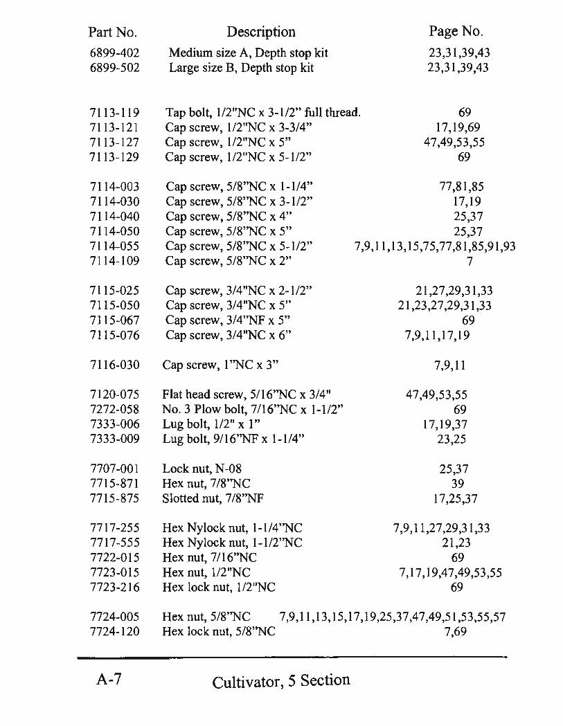
6899-402 6899-502
7113-119 7113-121 7113-127 7113-129
7114-003 7114-030 7114-040 7114-050 7114-055 7114-109
7115-025 7115-050 7115-067 7115-076
7116-030
7120-075 7272-058 7333-006 7333-009
7707-001 7715-871 7715-875
7717-255 7717-555 7722-015 7723-015 7723-216
Description
Medium size A, Depth stop kit Large size B, Depth stop kit
Page No.
23,31,39,43 23,31,39,43
Tap bolt, 1I2"NC x 3-112" full thread. Cap screw, 1I2''NC x 3-3/4"
69 17,19,69
47,49,53,55 69
Cap screw, 1I2"NC x 5" Cap screw, 1I2"NC x 5-112"
Cap screw, 5/8''NC x 1-114" Cap screw, 5/8''NC x 3-112" Cap screw, 5/8''NC x 4" Cap screw, 5/8''NC x 5" Cap screw, 5/8''NC x 5-112" Cap screw, 5/8"NC x 2"
Cap screw, 3/4"NC x 2-112" Cap screw, 3/4"NC x 5" Cap screw, 3/4"NF x 5" Cap screw, 3/4"NC x 6"
Cap screw, 1 ''NC x 3"
Flat head screw, 5/16''NC x 3/4" No.3 Plow bolt, 7116''NC x 1-112" Lug bolt, 112" xl" Lug bolt, 9/16''NF x 1-114"
Lock nut, N-08 Hex nut, 7/8"NC Slotted nut, 7/8''NF
Hex Nylock nut, 1-1/4''NC Hex Nylock nut, 1-1/2"NC Hex nut, 7/16''NC Hex nut, 1/2"NC Hex lock nut, 1/2"NC
77,81,85 17,19 25,37 25,37
7,9,11,13,15,75,77,81,85,91,93 7
21,27,29,31,33 21,23,27,29,31,33
69 7,9,11,17,19
7,9,11
47,49,53,55 69
17,19,37 23,25
25,37 39
17,25,37
7,9,11,27,29,31,33 21,23
69 7,17,19,47,49,53,55
69
7724-005 Hex nut, 5/8''NC 7,9,11,13,15,17,19,25,37,47,49,51,53,55,57 7724-120 Hex lock nut, 5/8''NC 7 ,69
A -7 Cultivator, 5 Section

Part No.
7725-002 7725-122 7725-138 7726-012 7807-001 7813-015 7815-014 7815-025 7816-020
7842-010 7843-015 7844-020
7845-020 7896-250 7896-500 7897-015 7910-162 7920-002 7920-006 7920-012
8036-025 8036-801 8115-013 8116-003 8116-006 8116-018 8116-032 8116-046 8116-601 8116-802 8116-803
Description
Hex nut, 3/4"NC Hex lock nut, 3/4"NF Hex jam nut, 7/8"NC Hex Nylock nut, 1 ''NC Ear washer, W-08 Flat washer, 112" Flat washer, 7/8" A-325 Hardened Flat washer, 7/8" Cut washer, 1", Pivot link
Lock washer, 3/8" Lock washer, 112" Lock washer, 5/8"
Page No.
7,9,11,17,19,21,23,27,29,31,33 69 39
7,9,11,13,15,49,53,55,59,61 25,37
47,49,53,55 37 25
21,23,27,29,31,33,39,59,61
45 17,19,47,49,53,55,69
7,9,11,13,15,25,37,49,51,53 55,57,69,75,77,81,85,91,93
Lock washer, 3/4" 7,9,11,17,19,21,23,,27,29,31,33,39 Machine bushing, 1-114" x 10ga, NR 27,29,31,33 Machine bushing, 1-1/2" x 10ga, NR 7,21,23 Machine bushing, 1-5/8" x 10ga, NR 17,19 Cotter pin, 5/32" x 1-112" 17,25,37 Hitch pin, #8, Cylinder lock 21,23,39,51,57 Lock pin, Pull eye 7 Snap pin, 1/2" x 4" 7
Pin, tongue pull eye, 1-1/2" x 5-112" Pin, wing lock Cap screw, 3/4"NC x 14-112" Bolt, 1 "NC x 6-114", W lNylock nut Bolt, 1-1/4"NC x 10-1/2", WlNylock nut Bolt, 1 ''NC x 5, WlNylock nut Bolt, l-1I4''NC x 7", W lNylock nut Bolt, 1''NC x 7-7/8", WlNylock nut Bolt, 1 ''NC x 5-3/4", WlNylock nut Bolt, 1-1/4''NC x 3-1/4" Bolt, l-1I2''NC x 4-118", W lNylock nut
Cultivator, 5 Section
7 51,57
7 47,49,53,55,59,61
7 45,47,53,55,59,61
9, II 13,15
47,49,53,55,59,61 27,29,31,33,35
21,23
A-8