43rd turbomachinery & 30 pump users symposia (pump & turbo
TRANSCRIPT
43rd Turbomachinery & 30th Pump Users Symposia (Pump & Turbo 2014) September 23-25, 2014 | Houston, TX | pumpturbo.tamu.edu
__________________________________________________________________________________________ Copyright© 2014 by Turbomachinery Laboratory, Texas A&M Engineering Experiment Station
TESTING OF GAS-LIQUID CENTRIFUGAL
SEPARATION AND COMPRESSION TECHNOLOGY
AT DEMANDING OPERATING CONDITIONS
William Maier
Principal Development Engineer
Dresser-Rand Company
Olean, New York, USA
716-375-3802
José L. Gilarranz R. Manager, Technology Development & Commercialization, ICS & Subsea
Dresser-Rand Company
Houston, Texas, USA
713-973-5365
Yuri Biba
Staff Aerodynamics Engineer
Dresser-Rand Company
Olean, New York, USA
716-375-3776
Daniel DeMore Staff Aero Design Engineer
Dresser-Rand Company
Bethlehem, Pennsylvania, USA
610-807-3821
William Maier is a Principal Development
Engineer with Dresser-Rand Company based
in Olean, New York. He has been with the
company since 1980. His latest activities are
centered on advanced subsea compression
and separation systems.
Mr. Maier has co-authored and presented
papers at numerous technical conferences including SYMCOM,
ASME IGTI, and TAMU Turbo-Symposium and currently holds
thirty six US Utility Patents. He received a B.Sc. degree from
Rochester Institute of Technology in Mechanical Engineering
in 1981. He is a member of ASME, ΤΒΠ, and ΦΚΦ.
Yuri Biba is a Staff Aero Performance
Engineer with Dresser-Rand Company, in
Olean, New York. He has been with the
company since 1992, involved in
turbocompressor selections, revamps and
testing, focusing on aerodynamic design,
analysis, performance prediction, and
optimization of centrifugal compressor
components.
Dr. Biba received his M.Sc. degree in Aeronautical Engineering (with Honors, 1984) and Ph.D. degree in
Mechanical Engineering (1987) from St. Petersburg State
Polytechnic University, Russia. He has authored, presented and
published technical papers on the subject of turbomachinery
aerodynamics and is a member of ASME.
José L. Gilarranz R. joined Dresser-Rand in
2002 and is currently the Manager for
Technology Development and
Commercialization of the DATUM ICS and
Subsea Product lines within Dresser-Rand
in Houston, Texas.
Dr. Gilarranz actively participates in new project development
and serves as the main technical and commercial contact
between Dresser-Rand and its clients in the area of compact
compression systems. Previously, Dr. Gilarranz was a Senior
Aero/Thermo Engineer and was heavily involved in the design, specification and use of advanced instrumentation for
development testing. He has also been engaged in shop and on-
site testing of centrifugal compression packages for both dry
and wet gas applications.
Prior to joining Dresser-Rand, Dr. Gilarranz worked as a
rotating Equipment Engineer for Lagoven S. A. (now Petróleos
de Venezuela - PDVSA) where his primary responsibility was
performance evaluation and prediction for compression
packages utilized by Lagoven in Lake Maracaibo.
Dr. Gilarranz received a B.S. (Cum Laude) in Mechanical
Engineering (1993) from the Universidad Simón Bolívar in
Caracas, Venezuela and an M.S. (1998) and Ph.D. (2001) in the area of experimental fluid mechanics from Texas A&M
University. He is a member of ASME, AIAA, and .
Daniel DeMore is a Staff Aero Design
Engineer with Dresser-Rand Company in
Bethlehem, Pennsylvania. Since joining the
company in 2010 he has been involved in
the aerodynamic design of single and
multiphase centrifugal compression system
components. He has over 17 years of
experience in radial turbomachinery aerodynamics in the gas turbine, air separation, and oil and gas industries. Mr. DeMore
received his B.S. degree in Mechanical Engineering (1991)
from Milwaukee School of Engineering, and an M.S. (1993)
and Ph.D. (2002) in Mechanical Engineering from Purdue
University. He is a member of ASME and AIAA.
__________________________________________________________________________________________ Copyright© 2014 by Turbomachinery Laboratory, Texas A&M Engineering Experiment Station
ABSTRACT
This paper describes experimental testing of a Rotating
Centrifugal Separator (RCS) integrated within the casing of a
centrifugal compressor. This unique combination of rotary gas-
liquid separation and centrifugal compression technologies
represents a new class of turbomachinery and leads to increased
system compactness by eliminating the need for large external
gravity based separation/scrubbing vessels often used on
traditional compressor trains. The OEM’s closed-loop,
multiphase flow test facility was used for measuring aero/thermodynamic and liquid separation performance of the
system. The test loop utilized inert gas as the vapor phase
component and a commercially available, stabilized liquid
hydrocarbon based solvent as the liquid phase component. The
phase of the test program discussed in the paper extends the
separation performance data previously obtained for the RCS
stage to more challenging separation conditions. The paper also
discusses the application of this technology in two production
type machines, and illustrates the intimate relationship that can
exist between the processing side and the rotating equipment
side of the oil and gas business.
INTRODUCTION
Conventional floating production storage and offloading
(FPSO) systems are usually designed with all the equipment
required to support the oil and gas activities arranged in
modules (see Figure 1).
Figure 1. Typical FPSO Arrangement Using Conventional
Compression Modules.
Typically several of these modules accommodate the
compression and associated process equipment, while others
accommodate power generation equipment, gas and liquid
processing facilities, and liquid handling and boosting systems.
The modules that accommodate the compression equipment
include gas/liquid scrubbing equipment, compression trains,
process piping, valves instrumentation and control devices, heat exchangers, flow measurement systems as well as the auxiliary
equipment required to support the rotating equipment (lube oil
system, seal gas systems, etc.). Several aspects of current
design practices contribute to large module sizes. These include
specified minimum straight upstream and downstream piping
lengths between conventional gravity based gas/liquid
separation and scrubbing equipment, heat exchangers and flow
measurement devices. Further, the superposition of
conservative sizing rules applied to individual components
results in larger and heavier modules and support structures.
In recent years there has been an interest in reducing the
size and weight of the compression modules by the application
of novel technology and/or the implementation of new design
rules that have emerged in the market place. Some examples
are the compact, printed circuit heat exchangers, advanced multi-hole, pressure balanced flow meters, and high speed
motors and magnetic bearings to eliminate the need for gear
boxes and bulky lubricating oil systems. In addition, the use of
hermetically sealed motor/compression systems, available from
several compressor OEMs, often allows for the elimination of
the gas conditioning system and dry gas seals.
Another target component in the size reduction efforts
applied to conventional gas compression modules is the
gas/liquid scrubbing equipment. Historically, gas dominated
compression services have used static gas/liquid scrubbers
composed of large vertical pressure vessels containing separation enhancing internals. These scrubbers are designed to
protect the compression equipment from potentially damaging
effects of liquids and suspended solids that can be part of the
incoming gas stream (e.g. erosion, fouling, etc.). Combinations
of various static scrubbing technologies are used in the internal
components in these vessels. The choice of one technology
over another may be based on the expected liquid loading of the
gas entering the scrubber, the composition of the liquid and
vapor stream entering the scrubber, the pressure at which the
scrubber is operating, as well as the end-user preference. The
selection of separator vessel diameter also plays a key role in
overall separation efficiency (Campbell 2004). Scrubbers with larger vessel diameter generally have better separation
efficiency. This of course means that effective gravity based
scrubbers tend to project a relatively large footprint within the
compression module. In general, for scrubbers operating at a
pressure above 500 psia (35 Bara), the length-to-diameter ratio
(L/D) of the scrubber vessel is usually set at a value of 5. The
height of these vessels often extends vertically upwards to an
extent that prohibits the installation of other equipment directly
above them in typical multi-deck offshore modules. As process
pressures increase, liquids become harder to separate, requiring
further increases in scrubber vessel diameters. This increase in diameter compounds into even further increases in module
weight and size due to required thickening of pressure vessel
walls.
To address this key aspect of compression module size, a
compressor OEM has developed a rotating centrifugal separator
(RCS) that can be integrated within the casing of centrifugal
compressors to provide the compressor stages with scrubber
quality gas. The rotary drum of the RCS, directly mounted on
the compressor shaft upstream of the first impeller, uses
density-based separation of liquids and gases, enhanced by
centripetal acceleration, similar to traditional static cyclonic
separation devices. A major difference between the rotary separator and static cyclones is the magnitude of centripetal

__________________________________________________________________________________________ Copyright© 2014 by Turbomachinery Laboratory, Texas A&M Engineering Experiment Station
body forces used in the separation process. With a rotating
drum, the RCS can achieve “G” forces that are an order of
magnitude larger than static cyclones, making the separation
system significantly more compact and capable of being
integrated within the compressor casing. This potential
difference in size is quantified in Figure 2 with a plot of
characteristic volume versus Souders-Brown gas loading K
factor for various separation technologies.
Thus, the integrated separator facilitates a significant
reduction in the size and footprint of the overall compression
train and associated gas/liquid separation equipment, while still providing sufficient protection to the compressor flow path.
Details describing the technology and its development may be
found in the works of Maier et al. (2010), Griffin and Maier
(2011).
The elimination and/or size reduction of the process
scrubber has also been considered for subsea compression
applications. Figure 3 shows a traditional subsea compression
process arrangement. In this system, a conventional, high
efficiency gravity based scrubber is combined with the slug
catching function and placed upstream of a motor/compressor
system. The compressor boosts the vapor phase of the wet gas
stream while the liquids removed by the scrubber are boosted by a subsea pump and recombined with the gas downstream of
the compressor. As mentioned above for the case of topside
equipment, sizing of the scrubber vessel to optimize the
separation performance may result in a large vessel. For subsea
applications, the compression and processing equipment has to
be designed not only to safely contain the internal pressure of
the process fluids, but also to accommodate the external
hydrostatic forces acting on the outside of the components. For
deep water applications, the external pressure can be as large
(or even larger) than the process fluid pressures. The
combination of large vessel size and the need to withstand both
internal and external forces often results in very large and heavy vessels, which may be unattractive due to the
problematic installation or intervention operations required.
Two alternative solutions have been developed to overcome
this issue. The first solution is based on the removal of the
scrubber/slug catcher vessel and subsequent use of a fluid
pressure boosting system that can handle a multiphase fluid
(Figure 4). This solution has the drawback of limited slug
handling capability and reliance on problematic multiphase
compression equipment. The second alternative is to retain a
smaller primary separation and slug catching vessel and to use
a wet gas tolerant compressor to boost the vapor dominant
stream and a liquid boosting system (subsea pump, or
pneumatic boosting system) to handle the liquid (Figure 5). For this OEM, the liquid tolerant compressor will include the
integrated separator to perform the scrubbing function inside
the compressor casing. When compared to alternate
configurations that are intended to compress the wet gas
directly, the integrated separator coupled with subsequent
handling (or boosting) of the vapor and the liquid phases as
separate streams allows for a reduction in the overall power
consumption of the wet stream boosting system. Also, keeping
the liquids out of the compressor flowpath allows for an
increase in the availability and reliability of the compressor as
it reduces the potential fouling and erosive agents that may enter the unit.
Figure 3. Typical Subsea Compression Process Arrangement.
Figure 4. Subsea Direct Wet Compression Process
Arrangement.
Figure 2. Comparison of Various Separation Technologies.
Multi-Stage
Static Scrubbers
In-line Axial Cyclones
RCS stageIn-line Rotary

__________________________________________________________________________________________ Copyright© 2014 by Turbomachinery Laboratory, Texas A&M Engineering Experiment Station
Figure 5. Subsea Compact Compression Process Arrangement.
Brownfields are another field of application where
significant benefits can be realized through size and weight
reduction of compression systems and associated process
equipment. Here the operator needs to increase the compression capacity of the facility by installing additional
compression trains. Brownfield facilities may have space and
weight constraints as well as locational constraints due to the
position of existing structures and modules. Often, there is
barely enough space for a compressor and driver in one
location and the scrubber must be located remotely requiring
problematic piping routing. The RCS system solution
favorably addresses these issues with only a minimal space and
weight increase over a conventional compressor and driver
alone.
TESTING BACKGROUND
Previous technical papers by Maier et al. (2010), Maier and
Biba (2010), Griffin and Maier (2011) describing the
development of the RCS stage have presented initial phases of
combined analytical design and test campaigns executed on a
scaled test rig (see Figure 6). This testing was used to optimize
the separator stage geometry with an emphasis on maximizing
separation efficiency while minimizing axial space claim of the
separator. These previous tests series were performed at
pressure levels between 40 psia (3 Bara) and 300 psia (20
Bara). This pressure limit was due to limitations of special flow visualization sight glasses in the inlet and discharge piping
and to drive power limitations. The sight glasses were
subsequently replaced with blind flanges and an alternate driver
was installed to allow for the higher pressure testing, up to 550
psia (38 Bara), reported in the present paper.
Figure 6. Solid Rendering of Separator Laboratory Test Rig.
Higher pressure testing extended the testing to higher
ranges of Separation Parameter (SP′). This non-dimensional
parameter was developed by the OEM (Maier et al. 2010) as a
way to characterize the degree of difficulty of separation for
rotating separator technology. SP′ is a primary parameter used
by the OEM to screen potential applications of this technology.
In addition to covering higher pressure testing, additional
testing was done to further characterize the capabilities of the
separator stage under both steady state conditions and under
conditions that were intended to simulate sudden liquid ingress.
Further extension of the SP′ experience range and additional full scale separator test programs are currently
underway as part of a joint industry program between the OEM
and an oil and gas operator. This demonstration program
includes testing of a 10 MW, hermetically sealed,
motor/compressor for topside and subsea applications. This
pilot test unit has nine stages arranged in two back to back
sections of compression within a single body (intercooled).
Figure 7 shows the compressor bundle and the rotor for the
above referenced pilot unit during assembly. This image,
showing the separator drums on each end of the rotor, clearly
illustrates the compactness of an RCS solution relative to the conventional static scrubber technologies.
Figure 7. Pilot Unit Compressor Bundle and Rotor.
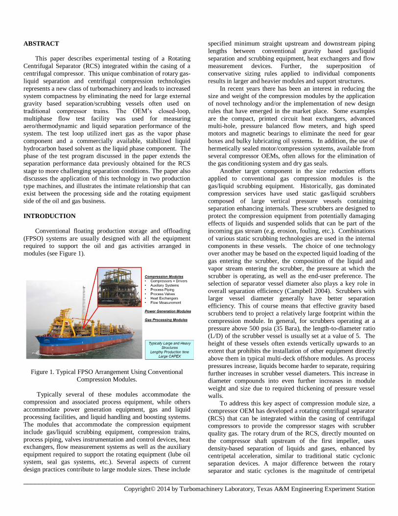
In addition to these test programs, the OEM has been
selectively introducing integrated, centrifugal separation
technology into the market. Figures 8a and 8b show a 3D
model and the actual hardware built for a centrifugal
compressor that incorporates the rotating centrifugal separator.
This unit, completed in 2014 for an oil and gas operator, will be
installed on an offshore platform in the Gulf of Mexico. The
compressor designed for discharge pressure 1120 psia (77
Bara) and capacity 119 MMSCFD (3.36 MMSCMD) has seven
stages of compression arranged in a straight through
configuration with the first being an RCS stage. Separated liquids exit the casing via the liquid drain nozzle (Figure 8a).
This unit was subjected to a factory acceptance test as part of
the client’s acceptance test requirements. The results of this
testing and a comparison with analytical predictions are also
presented in this paper.
RCS Stages
__________________________________________________________________________________________ Copyright© 2014 by Turbomachinery Laboratory, Texas A&M Engineering Experiment Station
Figure 8a. 3-D Rendering of an RCS Integrated Stage for a
Production, Offshore, GT Driven Compression Train.
Figure 8b. Internal Components of RCS Integrated Separator
for an Offshore, GT Driven Compression Train.
Table 1 summarizes information about the two test units
covered in this paper.
Table 1. Test Unit Summary.
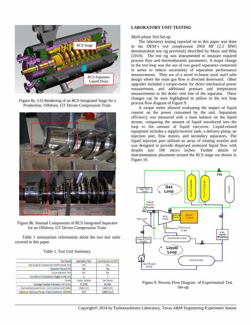
LABORATORY UNIT TESTING
Multi-phase Test Set-up
The laboratory testing reported on in this paper was done
in the OEM’s wet compression 2950 HP (2.2 MW)
demonstration test rig previously described by Maier and Biba
(2010). The test rig was instrumented to measure required
process flow and thermodynamic parameters. A major change
to the test loop was the use of two guard separators connected
in series to reduce uncertainty of separation performance
measurements. They are of a novel in-house axial swirl tube design where the main gas flow is directed downward. Other
upgrades included a torque-meter for direct mechanical power
measurement, and additional pressure and temperature
measurements in the drain/ vent line of the separator. These
changes can be seen highlighted in yellow in the test loop
process flow diagram of Figure 9.
A torque meter allowed evaluating the impact of liquid
content on the power consumed by the unit. Separation
efficiency was measured with a mass balance on the liquid
stream, comparing the amount of liquid introduced into the
loop to the amount of liquid carryover. Liquid-related equipment includes a supply/receiver tank, a delivery pump, an
injection port, flow meters, and secondary separators. The
liquid injection port utilized an array of misting nozzles and
was designed to provide dispersed atomized liquid flow with
droplet size 100 micro inches. Further details of
instrumentation placement around the RCS stage are shown in
Figure 10.
Figure 9. Process Flow Diagram of Experimental Test
Set-up.
RCS Separator Liquid Drain
RCS Stage
__________________________________________________________________________________________ Copyright© 2014 by Turbomachinery Laboratory, Texas A&M Engineering Experiment Station
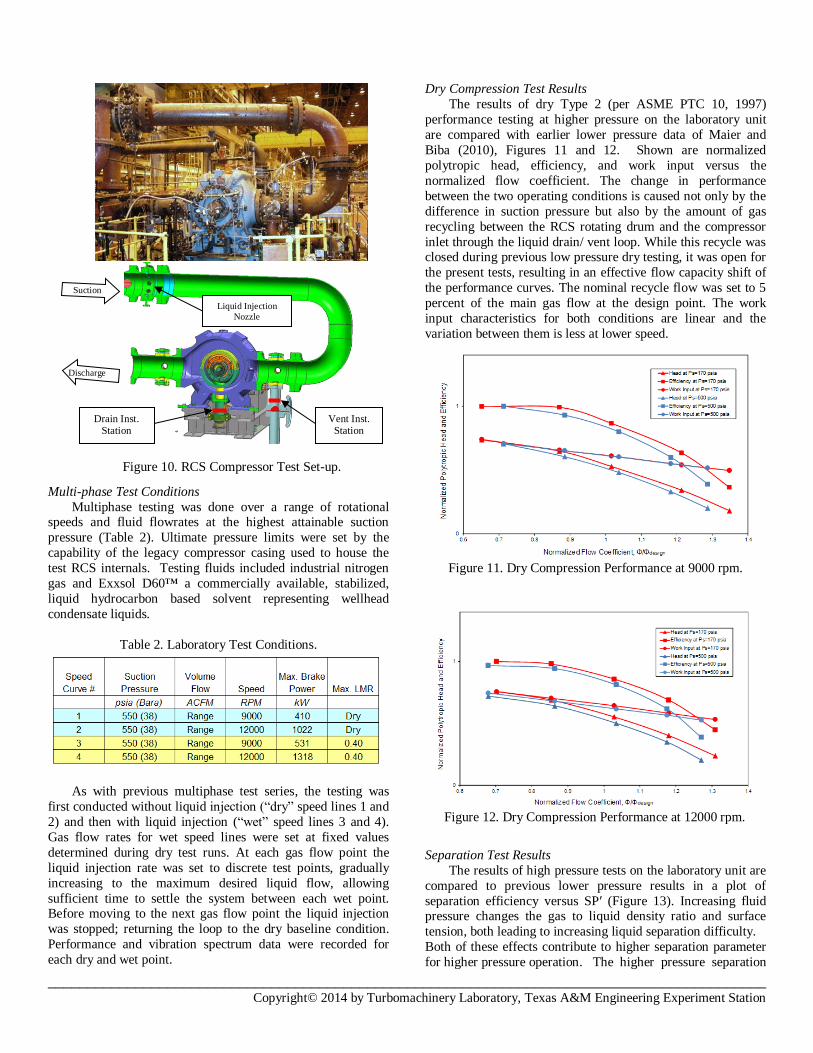
Multi-phase Test Conditions
Multiphase testing was done over a range of rotational speeds and fluid flowrates at the highest attainable suction
pressure (Table 2). Ultimate pressure limits were set by the
capability of the legacy compressor casing used to house the
test RCS internals. Testing fluids included industrial nitrogen
gas and Exxsol D60™ a commercially available, stabilized,
liquid hydrocarbon based solvent representing wellhead
condensate liquids.
Table 2. Laboratory Test Conditions.
As with previous multiphase test series, the testing was
first conducted without liquid injection (“dry” speed lines 1 and
2) and then with liquid injection (“wet” speed lines 3 and 4).
Gas flow rates for wet speed lines were set at fixed values
determined during dry test runs. At each gas flow point the
liquid injection rate was set to discrete test points, gradually
increasing to the maximum desired liquid flow, allowing
sufficient time to settle the system between each wet point. Before moving to the next gas flow point the liquid injection
was stopped; returning the loop to the dry baseline condition.
Performance and vibration spectrum data were recorded for
each dry and wet point.
Dry Compression Test Results
The results of dry Type 2 (per ASME PTC 10, 1997)
performance testing at higher pressure on the laboratory unit
are compared with earlier lower pressure data of Maier and
Biba (2010), Figures 11 and 12. Shown are normalized
polytropic head, efficiency, and work input versus the
normalized flow coefficient. The change in performance
between the two operating conditions is caused not only by the
difference in suction pressure but also by the amount of gas
recycling between the RCS rotating drum and the compressor
inlet through the liquid drain/ vent loop. While this recycle was closed during previous low pressure dry testing, it was open for
the present tests, resulting in an effective flow capacity shift of
the performance curves. The nominal recycle flow was set to 5
percent of the main gas flow at the design point. The work
input characteristics for both conditions are linear and the
variation between them is less at lower speed.
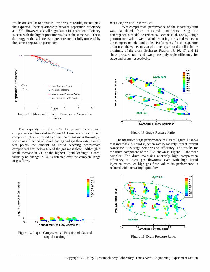
Separation Test Results
The results of high pressure tests on the laboratory unit are
compared to previous lower pressure results in a plot of
separation efficiency versus SP′ (Figure 13). Increasing fluid pressure changes the gas to liquid density ratio and surface
tension, both leading to increasing liquid separation difficulty.
Both of these effects contribute to higher separation parameter
for higher pressure operation. The higher pressure separation
Figure 11. Dry Compression Performance at 9000 rpm.
Figure 12. Dry Compression Performance at 12000 rpm.
Figure 10. RCS Compressor Test Set-up.
Suction
Discharge
Drain Inst. Station
Vent Inst. Station
Liquid Injection
Nozzle
__________________________________________________________________________________________ Copyright© 2014 by Turbomachinery Laboratory, Texas A&M Engineering Experiment Station
results are similar to previous low pressure results, maintaining
the expected linear relationship between separation efficiency
and SP′. However, a small degradation in separation efficiency
is seen with the higher pressure results at the same SP′. These
data suggest that all effects of pressure are not fully modeled by
the current separation parameter.
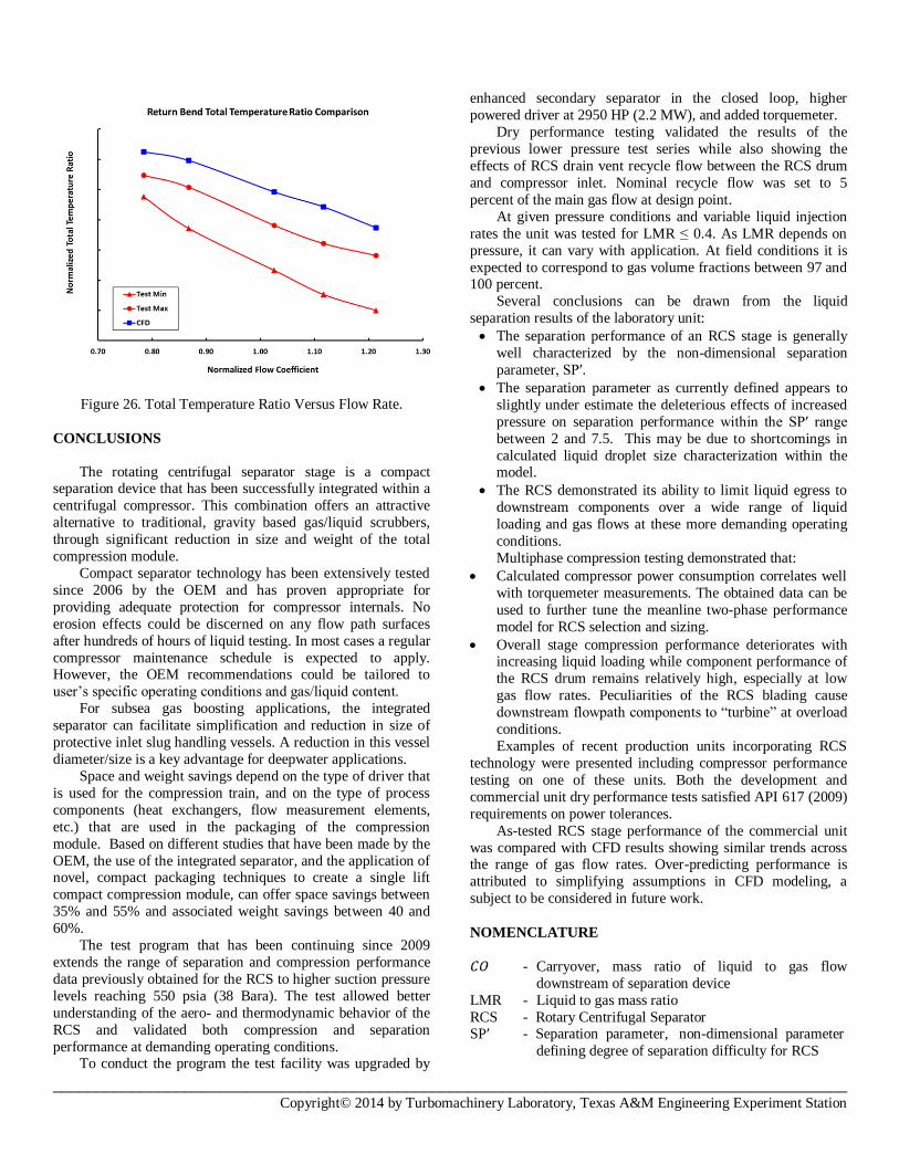
The capacity of the RCS to protect downstream
components is illustrated in Figure 14. Here downstream liquid
carryover (CO), expressed as a fraction of gas mass flowrate, is shown as a function of liquid loading and gas flow rate. For all
test points the amount of liquid reaching downstream
components was below 6% of the gas mass flow. Although a
small increase in CO at the highest liquid loadings is seen,
virtually no change in CO is detected over the complete range
of gas flows.
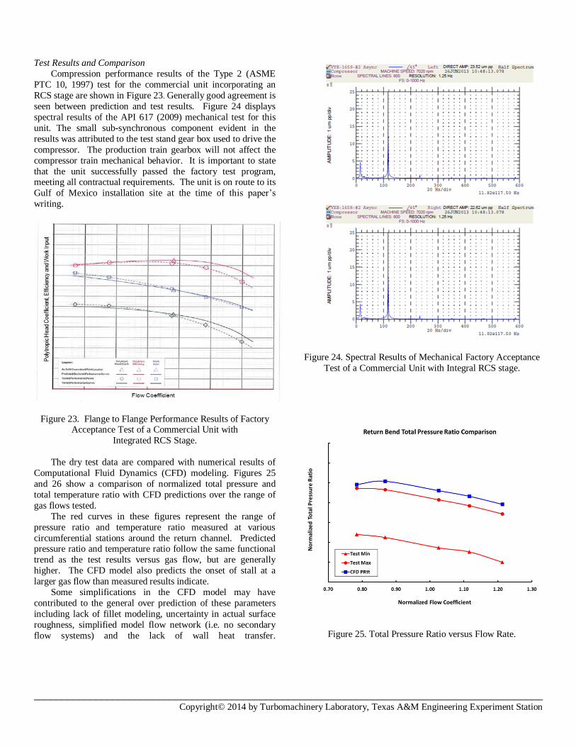
Wet Compression Test Results
Wet compression performance of the laboratory unit
was calculated from measured parameters using the
heterogeneous model described by Brenne et al. (2005). Stage
performance values were calculated using measured values at
the compressor inlet and outlet. Performance for the separator
drum used the values measured at the separator drain line in the
proximity of the drum discharge. Figures 15, 16, 17, and 18
show pressure ratio and two-phase polytropic efficiency for
stage and drum, respectively.
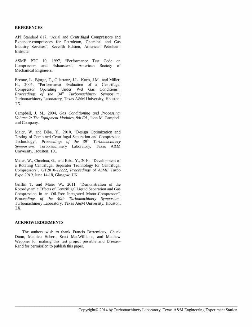
The measured stage performance results of Figure 17 show
that increases in liquid injection rate negatively impact overall
two-phase RCS stage compression efficiency. The results for
the drum component of the RCS shown in Figure 18 are more
complex. The drum maintains relatively high compression
efficiency at lower gas flowrates; even with high liquid
injection rates. At high gas flow values its performance is
reduced with increasing liquid flow.
Figure 14. Liquid Carryover as a Function of Gas and
Liquid Loading.
Figure 15. Stage Pressure Ratio
Figure 16. Drum Pressure Ratio.
Liq
uid
Carr
yo
ver
(% m
ass)
Figure 13. Measured Effect of Pressure on Separation
Efficiency.

__________________________________________________________________________________________ Copyright© 2014 by Turbomachinery Laboratory, Texas A&M Engineering Experiment Station
The observed effect of liquid loading on the separator
drum’s performance appears counter to the negative influences
shown in the overall separator stage efficiency of Figure 17.
However, this is simply a result of the assumed definition of
two-phase heterogeneous polytropic efficiency as defined by
Brenne et al. (2005). In the heterogeneous model, polytropic
work contains a term proportional to the mass of liquid handled
and to the pressure rise in the device (the RCS drum in this
case). Additionally, work input attributable to the drum is
affected by heat transfer between gas and cooler liquid. Thus,
the indicated drum compression efficiency is higher at larger liquid injection rates, especially at lower gas flow rates.
In case of extreme liquid injection load or/and unlikely
event of RCS separation performance deterioration,
unexpectedly large liquid carryover may occur. In such
circumstances compressor operator would notice increased
power consumption due to two-phase stage efficiency decrease,
as Figure 17 illustrates.
Stability margin may be also affected at increased
carryover, as its impact on compressor performance is greater
at low flow values, which is noticeable in Figure 15. Attempts
to increase rotational speed in order to maintain desired
discharge pressure may lead to approaching stability limit.
Another particularly interesting effect is illustrated in
Figure 19 where pressure ratio curves for drum and stage
converge and cross near a normalized flow coefficient of 1.3.
This cross-over implies that under these conditions the
downstream RCS stage components are absorbing gas power
and therefore not contributing positively to stage compression.
The ability to accurately predict RCS power consumption
at different liquid injection rates is important for design and
operation of two-phase compression units. To help achieve
accurate prediction, the heterogeneous model was enhanced to
account for secondary heat transfer effects in the liquid drain/
vent recycle path of the RCS stage. These effects were
experimentally measured during testing. Additionally, an extra
tuning parameter for drum liquid work in the stage power
balance was established. This parameter was adjusted to best
match the calculated power consumption with global torquemeter measurements. Figure 20, a comparison of
measured versus calculated stage power after tuning, shows
generally good agreement between calculation and
measurement. However, some measured values remain higher
than calculated values for some test points.
Figure 17. Stage Two-Phase Polytropic Efficiency.
Figure 18. Drum Two-Phase Polytropic Efficiency.
Figure 20. Measured and Calculated Power for
Multi-phase Tests.
Figure 19. Pressure Ratio: Drum and Stage.
Increasing
Liquid
Loading
Increasing
Liquid
Loading

__________________________________________________________________________________________ Copyright© 2014 by Turbomachinery Laboratory, Texas A&M Engineering Experiment Station
COMMERCIAL UNIT FACTORY ACCEPTANCE TEST
Test Set-up
The general layout and the instrumentation chart for the
test setup of the commercial multistage compressor described
earlier is shown in Figure 21. Additional instrumentation
included pressure and temperature probes at the return bend of
the RCS stage, and static pressure and temperature probes and a
flow meter in the RCS drain vent line.
Figure 21a. Factory Test Piping Shown in Front Elevation
View.
Figure 21b. Factory Test Instrumentation.
Only dry testing was performed on this unit. Although no separation performance could be obtained, this testing did
allow the validation of the RCS design and the OEM’s
prediction of its dry compression performance.
Performance Prediction
The results of dry performance testing on the RCS stage of
this compressor are compared to a CFD stage model. Several
views of the fluid volume for this model are shown in Figure
22. As shown in the figure, a full stage model of the separator
stage was used including complete inlet plenum and inlet guide
vane volumes, an arc segment model of the drum and diffuser
domains, and a full liquid collector volume. A hybrid mesh system was used with TET/prism meshes for the Inlet plenum,
IGV vane, and liquid collector domains, and block structured
meshes for the drum, diffuser, and return channel domains.
Fillets were not included in the drum and diffuser, blade
passages models. The process fluid, CO2, was modeled as ideal
gas.
ANSYS CFX version 15.0 was used as the flow solver
with k-epsilon turbulence modeling and scalable wall functions.
Wall boundaries were modeled as adiabatic using no-slip
boundary condition with surface roughness.
Circumferentially averaging “stage” interfaces were applied between the IGV and drum domains, the drum and
rotating diffuser domains, the stationary diffuser and return
channel domains, and at the inlet of the liquid collector. Inlet
total pressure boundary conditions were applied at the inlet of
the inlet plenum and mass flow outlet boundary conditions
applied at the collector outlet and return channel outlet
boundaries. A mass flow inlet boundary condition was applied
at the drain vent recycle inlet boundary. Actual test mass flow
rate, total temperature, and total pressure conditions were
modeled.
Figure 22. RCS Stage CFD Model Gas Volume.
Recycle
Inlet Main Inlet
Liquid Collector
Separator
Drum
__________________________________________________________________________________________ Copyright© 2014 by Turbomachinery Laboratory, Texas A&M Engineering Experiment Station
Test Results and Comparison
Compression performance results of the Type 2 (ASME
PTC 10, 1997) test for the commercial unit incorporating an
RCS stage are shown in Figure 23. Generally good agreement is
seen between prediction and test results. Figure 24 displays
spectral results of the API 617 (2009) mechanical test for this
unit. The small sub-synchronous component evident in the
results was attributed to the test stand gear box used to drive the
compressor. The production train gearbox will not affect the
compressor train mechanical behavior. It is important to state
that the unit successfully passed the factory test program, meeting all contractual requirements. The unit is on route to its
Gulf of Mexico installation site at the time of this paper’s
writing.
Figure 23. Flange to Flange Performance Results of Factory Acceptance Test of a Commercial Unit with
Integrated RCS Stage.
The dry test data are compared with numerical results of
Computational Fluid Dynamics (CFD) modeling. Figures 25
and 26 show a comparison of normalized total pressure and
total temperature ratio with CFD predictions over the range of
gas flows tested.
The red curves in these figures represent the range of
pressure ratio and temperature ratio measured at various
circumferential stations around the return channel. Predicted pressure ratio and temperature ratio follow the same functional
trend as the test results versus gas flow, but are generally
higher. The CFD model also predicts the onset of stall at a
larger gas flow than measured results indicate.
Some simplifications in the CFD model may have
contributed to the general over prediction of these parameters
including lack of fillet modeling, uncertainty in actual surface
roughness, simplified model flow network (i.e. no secondary
flow systems) and the lack of wall heat transfer.
Figure 24. Spectral Results of Mechanical Factory Acceptance
Test of a Commercial Unit with Integral RCS stage.
Figure 25. Total Pressure Ratio versus Flow Rate.
__________________________________________________________________________________________ Copyright© 2014 by Turbomachinery Laboratory, Texas A&M Engineering Experiment Station
Figure 26. Total Temperature Ratio Versus Flow Rate.
CONCLUSIONS
The rotating centrifugal separator stage is a compact separation device that has been successfully integrated within a
centrifugal compressor. This combination offers an attractive
alternative to traditional, gravity based gas/liquid scrubbers,
through significant reduction in size and weight of the total
compression module.
Compact separator technology has been extensively tested
since 2006 by the OEM and has proven appropriate for
providing adequate protection for compressor internals. No
erosion effects could be discerned on any flow path surfaces
after hundreds of hours of liquid testing. In most cases a regular
compressor maintenance schedule is expected to apply. However, the OEM recommendations could be tailored to
user’s specific operating conditions and gas/liquid content.
For subsea gas boosting applications, the integrated
separator can facilitate simplification and reduction in size of
protective inlet slug handling vessels. A reduction in this vessel
diameter/size is a key advantage for deepwater applications.
Space and weight savings depend on the type of driver that
is used for the compression train, and on the type of process
components (heat exchangers, flow measurement elements,
etc.) that are used in the packaging of the compression
module. Based on different studies that have been made by the
OEM, the use of the integrated separator, and the application of novel, compact packaging techniques to create a single lift
compact compression module, can offer space savings between
35% and 55% and associated weight savings between 40 and
60%.
The test program that has been continuing since 2009
extends the range of separation and compression performance
data previously obtained for the RCS to higher suction pressure
levels reaching 550 psia (38 Bara). The test allowed better
understanding of the aero- and thermodynamic behavior of the
RCS and validated both compression and separation
performance at demanding operating conditions. To conduct the program the test facility was upgraded by
enhanced secondary separator in the closed loop, higher
powered driver at 2950 HP (2.2 MW), and added torquemeter.
Dry performance testing validated the results of the
previous lower pressure test series while also showing the
effects of RCS drain vent recycle flow between the RCS drum
and compressor inlet. Nominal recycle flow was set to 5
percent of the main gas flow at design point.
At given pressure conditions and variable liquid injection
rates the unit was tested for LMR ≤ 0.4. As LMR depends on
pressure, it can vary with application. At field conditions it is
expected to correspond to gas volume fractions between 97 and 100 percent.
Several conclusions can be drawn from the liquid
separation results of the laboratory unit:
The separation performance of an RCS stage is generally
well characterized by the non-dimensional separation
parameter, SP′.
The separation parameter as currently defined appears to
slightly under estimate the deleterious effects of increased
pressure on separation performance within the SP′ range
between 2 and 7.5. This may be due to shortcomings in
calculated liquid droplet size characterization within the model.
The RCS demonstrated its ability to limit liquid egress to
downstream components over a wide range of liquid
loading and gas flows at these more demanding operating
conditions.
Multiphase compression testing demonstrated that:
Calculated compressor power consumption correlates well
with torquemeter measurements. The obtained data can be
used to further tune the meanline two-phase performance
model for RCS selection and sizing.
Overall stage compression performance deteriorates with increasing liquid loading while component performance of
the RCS drum remains relatively high, especially at low
gas flow rates. Peculiarities of the RCS blading cause
downstream flowpath components to “turbine” at overload
conditions.
Examples of recent production units incorporating RCS
technology were presented including compressor performance
testing on one of these units. Both the development and
commercial unit dry performance tests satisfied API 617 (2009)
requirements on power tolerances.
As-tested RCS stage performance of the commercial unit
was compared with CFD results showing similar trends across the range of gas flow rates. Over-predicting performance is
attributed to simplifying assumptions in CFD modeling, a
subject to be considered in future work.
NOMENCLATURE
- Carryover, mass ratio of liquid to gas flow
downstream of separation device
LMR - Liquid to gas mass ratio
RCS - Rotary Centrifugal Separator SP′ - Separation parameter, non-dimensional parameter
defining degree of separation difficulty for RCS
__________________________________________________________________________________________ Copyright© 2014 by Turbomachinery Laboratory, Texas A&M Engineering Experiment Station
REFERENCES
API Standard 617, “Axial and Centrifugal Compressors and
Expander-compressors for Petroleum, Chemical and Gas
Industry Services”, Seventh Edition, American Petroleum
Institute.
ASME PTC 10, 1997, “Performance Test Code on
Compressors and Exhausters”, American Society of
Mechanical Engineers.
Brenne, L., Bjorge, T., Gilarranz, J.L., Koch, J.M., and Miller,
H., 2005, “Performance Evaluation of a Centrifugal
Compressor Operating Under Wet Gas Conditions”,
Proceedings of the 34th Turbomachinery Symposium,
Turbomachinery Laboratory, Texas A&M University, Houston,
TX.
Campbell, J. M., 2004, Gas Conditioning and Processing.
Volume 2: The Equipment Modules, 8th Ed., John M. Campbell
and Company.
Maier, W. and Biba, Y., 2010, “Design Optimization and
Testing of Combined Centrifugal Separation and Compression
Technology”, Proceedings of the 39th Turbomachinery
Symposium, Turbomachinery Laboratory, Texas A&M
University, Houston, TX.
Maier, W., Chochua, G., and Biba, Y., 2010, “Development of
a Rotating Centrifugal Separator Technology for Centrifugal
Compressors”, GT2010-22222, Proceedings of ASME Turbo
Expo 2010, June 14-18, Glasgow, UK.
Griffin T. and Maier W., 2011, “Demonstration of the Rotordynamic Effects of Centrifugal Liquid Separation and Gas
Compression in an Oil-Free Integrated Motor-Compressor”,
Proceedings of the 40th Turbomachinery Symposium,
Turbomachinery Laboratory, Texas A&M University, Houston,
TX.
ACKNOWLEDGEMENTS
The authors wish to thank Francis Betremieux, Chuck
Dunn, Mathieu Hebert, Scott MacWilliams, and Matthew Weppner for making this test project possible and Dresser-
Rand for permission to publish this paper.