4/3-way servo solenoid directional control valves, pilot
TRANSCRIPT

1/16
4/3-way servo solenoid directional control valves, pilot operated, with electrical position feedback and on-board electronicsType 4WRLE 10...35, symbols E./W.
Sizes (NG) 10, 16, 25, 27, 35Unit series 3XMaximum working pressure P, A, B 350 bar (NG27: 280 bar)Nominal flow rate 50...1100 l/min (∆p = 10 bar)
RE 29089/01.09Replaces: 01.05
List of contentsContents PageFeatures 1Ordering data 2Accessories, function, sectional diagram 3Control oil supply 4Technical data 5 to 7On-board electronics 8Characteristic curves 9 to 11Unit dimensions 12 to 15
Features– Pilot operated 4/3-way servo solenoid directional control
valves NG10 to NG35, with approx. 20 % overlap– Pilot valve NG6, with control piston and sleeve in servo
quality, actuated on one side, 4/4 fail-safe position when switched off
– Control solenoid with electrical position feedback and on-board electronics (OBE), calibrated at the factory
– Main stage with position feedback– Electronically calibrated and compensated overlap– Spool with linear travel, with anti-rotation element– Flow characteristic
• S = Progressive• NG16, 25 and 27 with load tap C1/C2
– For subplate attachment, mounting hole configuration NG10 to ISO 4401-05-05-0-05, NG16 to ISO 4401-07-07-0-05, NG25/27 to ISO 4401-08-08-0-05 and NG35 to ISO 4401-10-09-0-05
– Subplates as per Technical Data Sheet, NG10 RE 45055,NG16 RE 45057, NG25/27 RE 45059 and NG35 RE 45060 (order separately)
– Plug-in connectors to DIN 43563-AM6,see Technical Data Sheet RE 08008 (order separately)
For information regarding the available spare parts see:www.boschrexroth.com/spc
Court
esy
of CM
A/F
lodyn
e/H
ydra
dyn
e
Motion C
ontr
ol
Hyd
raulic
P
neu
mat
ic
Ele
ctrica
l
Mec
han
ical
(
800)
426-5
480
ww
w.c
maf
h.c
om

2/16 Bosch Rexroth AG Hydraulics 4WRLE 10...35 RE 29089/01.09
Ordering data
2) NG35 is a high-flow version of NG32, ports P, A, B and T have ∅ 50 mm in the main stage. Contrary to standard ISO 4401-10-09-0-05, ports P, A, B and T may be drilled to max. ∅ 48 mm in the control block. These valves therefore offer higher flow rates QA : QB
Further information in plain text
M = NBR seals,suitable for mineral oils
(HL, HLP)to DIN 51524Interface for
trigger electronicsA1 = Setpoint input ±10 V
Electrical connectionK0 = without plug-in connector,
with plug to DIN 43563-AM6Order plug-in
connector separatelyControl oil supply “x”,
control oil return “y”No desig. = “x” = external, “y” = externalE = “x” = internal, “y” = externalET = “x” = internal, “y” = internalT = “x” = external, “y” = internal
Voltage supply of trigger electronics G24 = +24 V DC
3X = Unit series 30 to 39(installation and connection dimensions unchanged)
J = Overlap compensation signalSee characteristic curve range: +0.5 V
Flow characteristicS = Progressive
Nominal flow rate at 10 bar valve pressure difference(5 bar per metering notch)
NG1050 = 50 l/min80 = 80 l/min
NG16180 = 180 l/min
NG25350 = 350 l/min
NG27430 = 430 l/min 1)
NG351100 = 1100 l/min 2)
4WRL E S J 3X G24 K0 A1 M *
1) NG27 is a high-flow version of NG25, ports P, A, B and T have ∅ 32 mm in the main stage. Contrary to standard ISO 4401-08-08-0-05, ports P, A, B and T may be drilled to max. ∅ 30 mm in the control block. These valves therefore offer higher flow rates QA : QB
A B
P T
A B
P T
C1
C2
A B
P T
A B
P T
A B
P T
A B
P T
C1
C2
A B
P T
A B
P T
C1
C2
A B
P T
A B
P T
With on-board electronics = ENG10 = 10NG16 = 16NG25 = 25NG27 1) = 27 NG35 2) = 35Control spool symbols = E, E1
= E (Z), E1 (Z)
= W, W1
= W (Z), W1 (Z)
= E4
= W4
Transitional symbols
With symbol E1, E1(Z), E4, W1(Z), W4:P → A: qv B → T: qv/2P → B: qv/2 A → T: qv
With load tap C1/C2 (NG16, 25, 27) = Z
Court
esy
of CM
A/F
lodyn
e/H
ydra
dyn
e
Motion C
ontr
ol
Hyd
raulic
P
neu
mat
ic
Ele
ctrica
l
Mec
han
ical
(
800)
426-5
480
ww
w.c
maf
h.c
om

Hydraulics Bosch Rexroth AGRE 29089/01.09 4WRLE 10...35 3/16
Accessories, not included in deliveryFastening bolts NG10 4 x ISO 4762-M6 x 40-10.9-N67F821 70 2 910 151 209
NG16 2 x ISO 4762-M6 x 45-10.9-N67F821 70 2 910 151 2114 x ISO 4762-M10 x 50-10.9-N67F821 70 2 910 151 301
NG25/27 6 x ISO 4762-M12 x 60-10.9-N67F821 70 2 910 151 354NG35 6 x ISO 4762-M20 x 90-10.9-N67F821 70 2 910 151 532Plug-in connectors 6P+PE, also see RE 08008
KS 1 834 482 022KS 1 834 482 026MS 1 834 482 023MS 1 834 482 024KS 90° 1 834 484 252
Testing and service equipment– Test box type VT-PE-TB3, see RE 30065 – Test adapter 6P+PE type VT-PA-2, see RE 30068
Function, sectional diagram
Functional descriptionWhen the control solenoid is not actuated, the control spool is held by springs in the fail-safe position, and the main stage spool remains in its spring-centered mid position.In the on-board electronics, the pre-defined setpoint is compared with the actual value for the position of the main stage control spool. In the event of an error signal, the control solenoid is actuated, and the pilot spool is moved as the magnetic force changes. The flow released through the control cross-sections causes the main control spool to move. The spool stroke is controlled proportionately to the setpoint of 0.5...10 V between 20...100 %. If the input setpoint is < ± 0.5 V, the control spool is held in the spring-centered, overlapped mid position.
The control oil is conveyed to the pilot valve either internally via port P or externally via port X. The oil returns to the tank internally via port T or externally via port Y.
Power failureIn the event of a power failure or an open circuit, the on-board electronics cut off the electricity to the control solenoid and the pilot spool moves to the fail-safe position, relieving the control oil chambers of the main stage. The main stage control spool is held by springs in mid position.
1
3
TC1
A P B
X C2 Y
2
ConstructionThe valve consists of three main assemblies:– Pilot valve (1) with control spool and sleeve, return
springs, control solenoid and inductive position transducer
– Main stage (2) with centering springs and position feedback
– On-board trigger electronics (3)
Court
esy
of CM
A/F
lodyn
e/H
ydra
dyn
e
Motion C
ontr
ol
Hyd
raulic
P
neu
mat
ic
Ele
ctrica
l
Mec
han
ical
(
800)
426-5
480
ww
w.c
maf
h.c
om
4/16 Bosch Rexroth AG Hydraulics 4WRLE 10...35 RE 29089/01.09
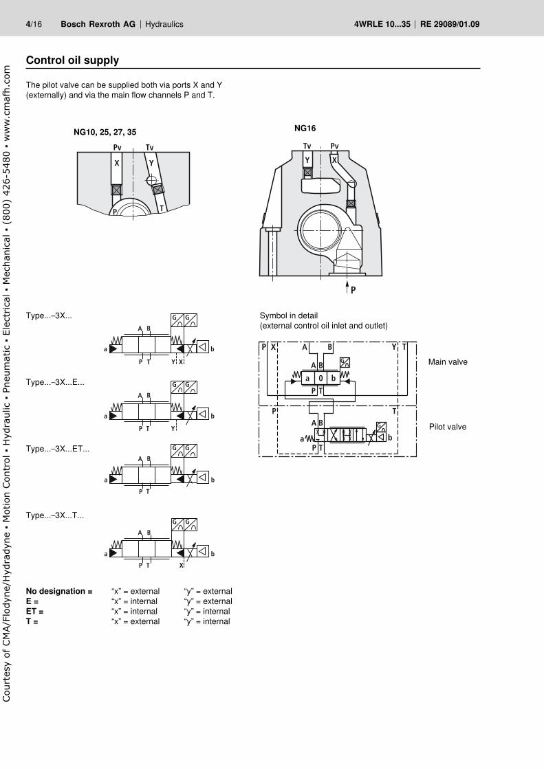
Control oil supply
The pilot valve can be supplied both via ports X and Y (externally) and via the main flow channels P and T.
NG10, 25, 27, 35 NG16
Symbol in detail(external control oil inlet and outlet)
Main valve
Pilot valve
Type...–3X...
Type...–3X...E...
Type...–3X...ET...
Type...–3X...T...
No designation = “x” = external “y” = externalE = “x” = internal “y” = externalET = “x” = internal “y” = internalT = “x” = external “y” = internal
X Y
Pv Tv
P T
A B
P T X
G G
ba
Y X
PvTv
P
P T
TP
A
A
B
B
Ta b
P
A B
0a b
G
G
XP Y T
A B
P T Y X
G G
ba
A B
P T Y
G
ba
G
A B
P T
G
ba
G
Court
esy
of CM
A/F
lodyn
e/H
ydra
dyn
e
Motion C
ontr
ol
Hyd
raulic
P
neu
mat
ic
Ele
ctrica
l
Mec
han
ical
(
800)
426-5
480
ww
w.c
maf
h.c
om

Hydraulics Bosch Rexroth AGRE 29089/01.09 4WRLE 10...35 5/16
Technical data
GeneralConstruction Spool type valve, pilot operatedActuation Servo solenoid directional control valve NG6, with position controller
for pilot valve and main stageType of mounting Subplate, mounting hole configuration NG10...35 to ISO 4401-...Installation position OptionalAmbient temperature range °C –20...+50Weight kg NG10 8.7 NG16 10.6 NG25 18.4 NG27 18.4 NG35 81Vibration resistance, test condition Max. 25 g, shaken in 3 dimensions (24 h)
Static/DynamicOverlap in mid position ª18...22 % of spool stroke, electrically compensated for UD–E ±0.5 VSpool stroke, main stage ± mm 4 7 10 10 12,5Control oil volume of main stage 100 % cm3 1.1 4.3 11.3 11.3 41.5Control oil requirement 0...100 %,(at X = 100 bar) l/min 2.2 4.7 11.7 11.7 15.6Hysteresis % <0.1, scarcely measurableManufacturing tolerance % < ± 5 (Qmax)Response time for 0...100 %, (at X = 100 bar) ms <40 <80 <80 <80 <130Response time for 0...100 %, (at X = 10 bar) ms <150 <250 <250 <250 <500Switch-off behavior After electrical switch-off (pilot valve in fail-safe)
Main stage moves to spring-centered overlapped mid positionThermal drift <1 % at ∆T = 40 °CCalibration At the factory ±1 %, see flow curveElectromagnetic compatibility EN 61000-6-2: 2002-08
EN 61000-6-3: 2002-081) The purity classes stated for the components must be complied with in hydraulic systems.
Effective filtration prevents problems and also extends the service life of components. For a selection of filters, see Technical Data Sheets RE 50070, RE 50076 and RE 50081.
2) Flow rate at a different ∆p Qx = Qnom · ∆px5!w
Hydraulic (measured with HLP 46, oil = 40 °C ±5 °C)Pressure fluid Hydraulic oil to DIN 51524...535, other fluids after prior consultationViscosity range recommended mm2/s 20...100
max. permitted mm2/s 10...800Pressure fluid temperature range °C –20...+70Maximum permissible degree of contamination of pressure fluidPurity class to ISO 4406 (c) Class 18/16/13 1)
Flow direction See symbolNominal flow at∆p = 5 bar per notch 2) l/min
NG10 NG16 NG25 NG27 NG3550, 80 180 350 430 1100
Max. Ports P, A, Bworking (external control oil inlet) bar 350 350 350 280 350pressure Ports P, A, B, X bar 280 Ports T, Y bar 250Min. control oil pressure in “pilot stage” bar 8Qmax l/min 170 450 900 1000 3500QN pilot valve (inlet)∆p = 35 bar l/min 2 4 12 12 40Leakage of pilot valve at X = 100 bar cm3/min <150 <180 <350 <500 <1100Leakage of main stage control spool symbols “E” at P = 100 bar l/min <0.25 <0.4 <0.6 <0.6 <1.1
Court
esy
of CM
A/F
lodyn
e/H
ydra
dyn
e
Motion C
ontr
ol
Hyd
raulic
P
neu
mat
ic
Ele
ctrica
l
Mec
han
ical
(
800)
426-5
480
ww
w.c
maf
h.c
om

6/16 Bosch Rexroth AG Hydraulics 4WRLE 10...35 RE 29089/01.09
Technical data
ImportantPilot operated 4/3-way servo solenoid directional control valves with positive overlap perform their function in open or closed-loop-controlled axes and have approx. 20 % overlap when switched off.This condition does not constitute an active fail-safe position. For this reason, many applications require the use of “external check valves” or certain sandwich-mounted valves, which must be taken into account during the On/Off switching sequence.
Electric pilot valve NG6, trigger electronics integrated in the valveCyclic duration factor % 100 EDDegree of protection IP 65 to DIN 40050 and IEC 14434/5Connection Plug-in connector 6P+PE, DIN 43563Power supplyTerminal A:Terminal B: 0 V
24 V DCnommin. 21 V DC/max. 40 V DCRipple max. 2 V DC
Power consumption Solenoid h 45 mm = 40 VA max.External fuse 2,5 AF
Input, “Standard” versionTerminal D: UETerminal E:
Differential amplifier, Ri = 100 kΩ0...±10 V0 V
Max. differential input voltage at 0 V
D → BE → B 6 max. 18 V DC
Test signal, “Standard” versionTerminal F: UTestTerminal C:
LVDT0...±10 VReference 0 V
Protective conductor and screen See pin assignmentRecommended cable See pin assignment
up to 20 m 7 x 0.75 mm2
up to 40 m 7 x 1 mm2
Calibration Overlap and P–A at +8 V, calibrated at the factory, see valve characteristic curve
Version: Standard
+/–10V
–10V… 0… +10V
LVDT Sign.+/–10V
Logic1 or 2Stage
P-B
P-A
Stroke
II sign.
Stroke
II sign.
Supply 24V =
Signal: 0…+/–10 V
LVDT Sign.: 0…+/–10 V
DC/DC LVDTSignal: +/–10V
NG6/10
Mainstage
Court
esy
of CM
A/F
lodyn
e/H
ydra
dyn
e
Motion C
ontr
ol
Hyd
raulic
P
neu
mat
ic
Ele
ctrica
l
Mec
han
ical
(
800)
426-5
480
ww
w.c
maf
h.c
om
Hydraulics Bosch Rexroth AGRE 29089/01.09 4WRLE 10...35 7/16
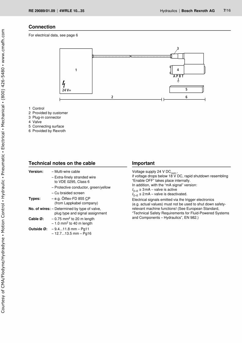
ConnectionFor electrical data, see page 6
Technical notes on the cableVersion: – Multi-wire cable – Extra-finely stranded wire
to VDE 0295, Class 6 – Protective conductor, green/yellow – Cu braided screenTypes: – e.g. Ölflex-FD 855 CP
(from Lappkabel company)No. of wires: – Determined by type of valve,
plug type and signal assignmentCable Ø: – 0.75 mm2 to 20 m length – 1.0 mm2 to 40 m lengthOutside Ø: – 9.4...11.8 mm – Pg11 – 12.7...13.5 mm – Pg16
ImportantVoltage supply 24 V DCnom.,if voltage drops below 18 V DC, rapid shutdown resembling “Enable OFF” takes place internally.In addition, with the “mA signal” version:ID–E ≧ 3 mA – valve is activeID–E ≦ 2 mA – valve is deactivated.Electrical signals emitted via the trigger electronics (e.g. actual values) must not be used to shut down safety- relevant machine functions! (See European Standard, “Technical Safety Requirements for Fluid-Powered Systems and Components – Hydraulics”, EN 982.)
1 Control2 Provided by customer3 Plug-in connector4 Valve5 Connecting surface6 Provided by Rexroth
1
24 V=
3
4
5
A P B T
62
Court
esy
of CM
A/F
lodyn
e/H
ydra
dyn
e
Motion C
ontr
ol
Hyd
raulic
P
neu
mat
ic
Ele
ctrica
l
Mec
han
ical
(
800)
426-5
480
ww
w.c
maf
h.c
om

8/16 Bosch Rexroth AG Hydraulics 4WRLE 10...35 RE 29089/01.09
Pin assignment 6P+PEVersion A1: UD–E ±10 V(Ri = 100 kΩ)
On-board electronicsBlock diagram/pin assignmentVersion A1: UD–E ±10 V
A +24 V =+24 V =
B 0 V0V
Ventil
Differenz-verstärker
LVDT Signal 10 V
C 0 V intern(Ref.-0)
D
E100k
10kF
10 V (Signal)
SL
0 V (Signal)UETest
UB
prot. groundSL
ABC
F
Logik
+UB
+UB
Referenz-Null*
Sollwert 0… 10 V
Schutzleiter
Abschirmung
2.5 AF +24 V=
0 V
Versorgung
* Nicht mit Versorgungs-Null verbinden!
Haupt-stufe
Differenz-verstärker
Vorsteuer-stufe
Versorgungs-Null
100k10k
100k
DC
DC
+15 V–15 V
PID+–PD
+–1 –15 V=
0…±10 V
2 ref. 0
3 +15 V=
4 Signal
S
4/3-Regel-Wegeventil
U
S
U
Signal 4/3-Regel-Wegeventil
A B
P TA B
P T
A B
P T
Istwert 0… 10 V
DE
UD–E0…+10 V
UD–E0 V
UD–E
UD–E0…–10 V
Power supply
Supply zero
Reference zero*
Setpoint 0...±10 V
Actual value 0...±10 V
Protective conductor
Screen
Valve
0 V internal
(ref. 0)
LVDT signal
±10 V
Differential
amplifi er
Logics
4/3-way servo solenoid
directional control valve
Signal4/3-way servo so-
lenoid directional
control valve
Main stage
Pilot stage
* Do not connect to supply zero!
Differ-
ential
amplifi er
Court
esy
of CM
A/F
lodyn
e/H
ydra
dyn
e
Motion C
ontr
ol
Hyd
raulic
P
neu
mat
ic
Ele
ctrica
l
Mec
han
ical
(
800)
426-5
480
ww
w.c
maf
h.c
om

Hydraulics Bosch Rexroth AGRE 29089/01.09 4WRLE 10...35 9/16
Characteristic curves (measured with HLP 46, oil = 40 °C ±5 °C)
* Comp. UD–E ±0.5 V factory setting ±1 %** QP–A at +8 V [UD–E] manufacturing tolerance Qmax ≦ ±5 %
Flow rate – signal functionQ = f (UD–E)
Symbol E(Z), W(Z) (QA : QB = 1 : 1)E1(Z), W1(Z) (QA : QB = 2 : 1)
20 6040 80 100%
UD-E
Hub(%)
comp.*
-80 -60 -40 -20 0
2 64 8 (V)10-10 -8 -6 -4 - 2 - 0,5 0 0,5
20
60
40
80A B
P T
A B **
P T
100%
0
P-AB-T
B-T(2:1)
P-B(2:1)
P-BA-T
Volu
men
stro
m Q
-100%-100%
-80
-60
-40
-20
20
60
40
80
-20
-60
-40
-80
A B
P T
A B
P T
A B
P T
100%
0
P-A
P-B
A-T
B-T
Volu
men
stro
m Q
20 6040 80 100%
UD-E
Hub(%)
comp.*
-80 -60 -40 -20 0
2 64 8 (V)10-10 -8 -6 -4 - 2 0 0,5-0,5
-100%-100%
**
Control spool with asymmetric metering notchesControl spools with asymmetric metering notches are available in a ratio of 2:1 for the purpose of adaptation to differential cylinders.
Control spools in a differential circuitIn order to produce differential circuits, valve spools with a 4th position are available.It is sufficient to install a check valve in the consumer lines.
In addition, a control spool (symbol) with internal B-P con-nection is employed for certain branch-oriented solutions. However, we recommend that you consult the BRH Application Center with regard to these special symbols, as a simulation or knowledge of this type of system is usually required.
Flow in mid position, “leakage oil pressure relief”With symbol “E”, leakage oil in the two work chambers A and B of the control piston gives rise to a build-up of pres-sure in A or B, which then causes a connecting cylinder to drift out of position.In many cases, the “W” symbol is a better solution. With a setpoint of “0”, the control piston moves into the over-lapped mid position. In this mid position, pressure is then relieved from ports A and B with 1 % ± 0.5 % QN to T. This also supports the function of external check valves.
A B
2 : 1
P T XY
G G
A B
P T XY
G G
Symbol E4, W4 (QA : QB = 2 : 1)
Flo
w r
ate
QFl
ow
rate
Q
Stroke (%)
Stroke (%)
Court
esy
of CM
A/F
lodyn
e/H
ydra
dyn
e
Motion C
ontr
ol
Hyd
raulic
P
neu
mat
ic
Ele
ctrica
l
Mec
han
ical
(
800)
426-5
480
ww
w.c
maf
h.c
om

10/16 Bosch Rexroth AG Hydraulics 4WRLE 10...35 RE 29089/01.09
Characteristic curves (measured with HLP 46, oil = 40 °C ±5 °C)
A B
P T Y X
G G A BC1
m
C2P T XY
G G
Load tap C1/C2To compensate for fluctuations in the load or supply pressure, 4/3-way servo solenoid directional control valves are combined with pressure compensators. The load is tapped via a shuttle valve for the NG10 and 35, and via two additional ports C1 and C2 for the NG16, 25 and 27.The pressure compensator therefore always receives the correct pressure signal even in the event of negative load.When using pressure compensators, an external control oil supply should always be selected.
NG16, 25, 27NG10, 35
Court
esy
of CM
A/F
lodyn
e/H
ydra
dyn
e
Motion C
ontr
ol
Hyd
raulic
P
neu
mat
ic
Ele
ctrica
l
Mec
han
ical
(
800)
426-5
480
ww
w.c
maf
h.c
om

Hydraulics Bosch Rexroth AGRE 29089/01.09 4WRLE 10...35 11/16
Characteristic curves (measured with HLP 46, oil = 40 °C ±5 °C)
NG10
NG16
NG25/27
NG35
Response time (at X = 100 bar)
Open Close
0 25ms 50ms0
20
40
60
80
100U E
%
10
30
50
70
90
0 25ms 50ms0
20
40
60
80
100
U E %
10
30
50
70
90
0 50ms 100ms0
20
40
60
80
100
U E %
10
30
50
70
90
0 50ms 100ms
50ms 100ms 50ms 100ms
0
20
40
60
80
100
U E %
10
30
50
70
90
00
20
40
60
80
100
U E %
10
30
50
70
90
00
20
40
60
80
100
U E %
10
30
50
70
90
0 100ms 200ms0
20
40
60
80
100
U E %
10
30
50
70
90
100ms 200ms00
20
40
60
80
100
U E %
10
30
50
70
90
Court
esy
of CM
A/F
lodyn
e/H
ydra
dyn
e
Motion C
ontr
ol
Hyd
raulic
P
neu
mat
ic
Ele
ctrica
l
Mec
han
ical
(
800)
426-5
480
ww
w.c
maf
h.c
om
12/16 Bosch Rexroth AG Hydraulics 4WRLE 10...35 RE 29089/01.09
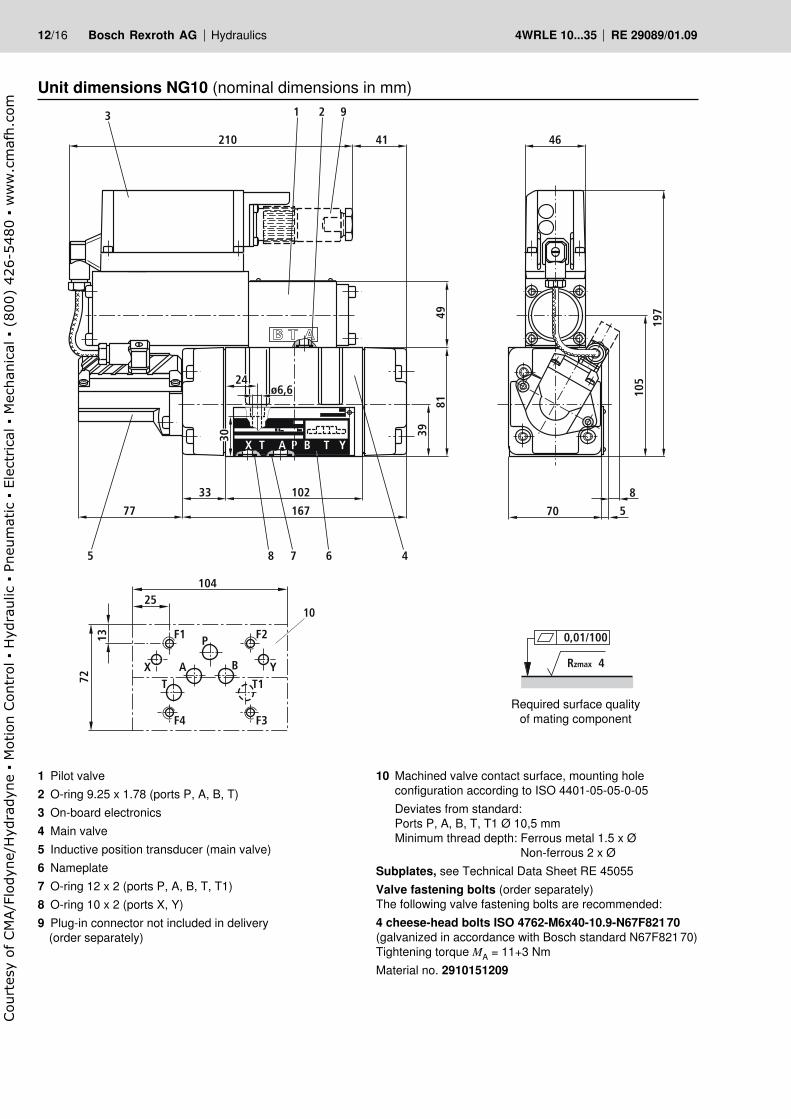
Unit dimensions NG10 (nominal dimensions in mm)
1 Pilot valve2 O-ring 9.25 x 1.78 (ports P, A, B, T)3 On-board electronics4 Main valve5 Inductive position transducer (main valve)6 Nameplate7 O-ring 12 x 2 (ports P, A, B, T, T1)8 O-ring 10 x 2 (ports X, Y)9 Plug-in connector not included in delivery
(order separately)
10 Machined valve contact surface, mounting holeconfiguration according to ISO 4401-05-05-0-05
Deviates from standard:Ports P, A, B, T, T1 Ø 10,5 mmMinimum thread depth: Ferrous metal 1.5 x Ø
Non-ferrous 2 x ØSubplates, see Technical Data Sheet RE 45055Valve fastening bolts (order separately)The following valve fastening bolts are recommended:4 cheese-head bolts ISO 4762-M6x40-10.9-N67F821 70(galvanized in accordance with Bosch standard N67F821 70) Tightening torque MA = 11+3 NmMaterial no. 2910151209
Required surface qualityof mating component
T TA P BX Y
77
5 8 7 6 4
167
210 41
3
102
8149
39
33
ø6,6
30
70
8
5
197
105
46
1 2 9
24
10
72
P
T T1A B
F2F1
X Y
F3F4
25
13
104
0,01/100
Rzmax 4
Court
esy
of CM
A/F
lodyn
e/H
ydra
dyn
e
Motion C
ontr
ol
Hyd
raulic
P
neu
mat
ic
Ele
ctrica
l
Mec
han
ical
(
800)
426-5
480
ww
w.c
maf
h.c
om
Hydraulics Bosch Rexroth AGRE 29089/01.09 4WRLE 10...35 13/16
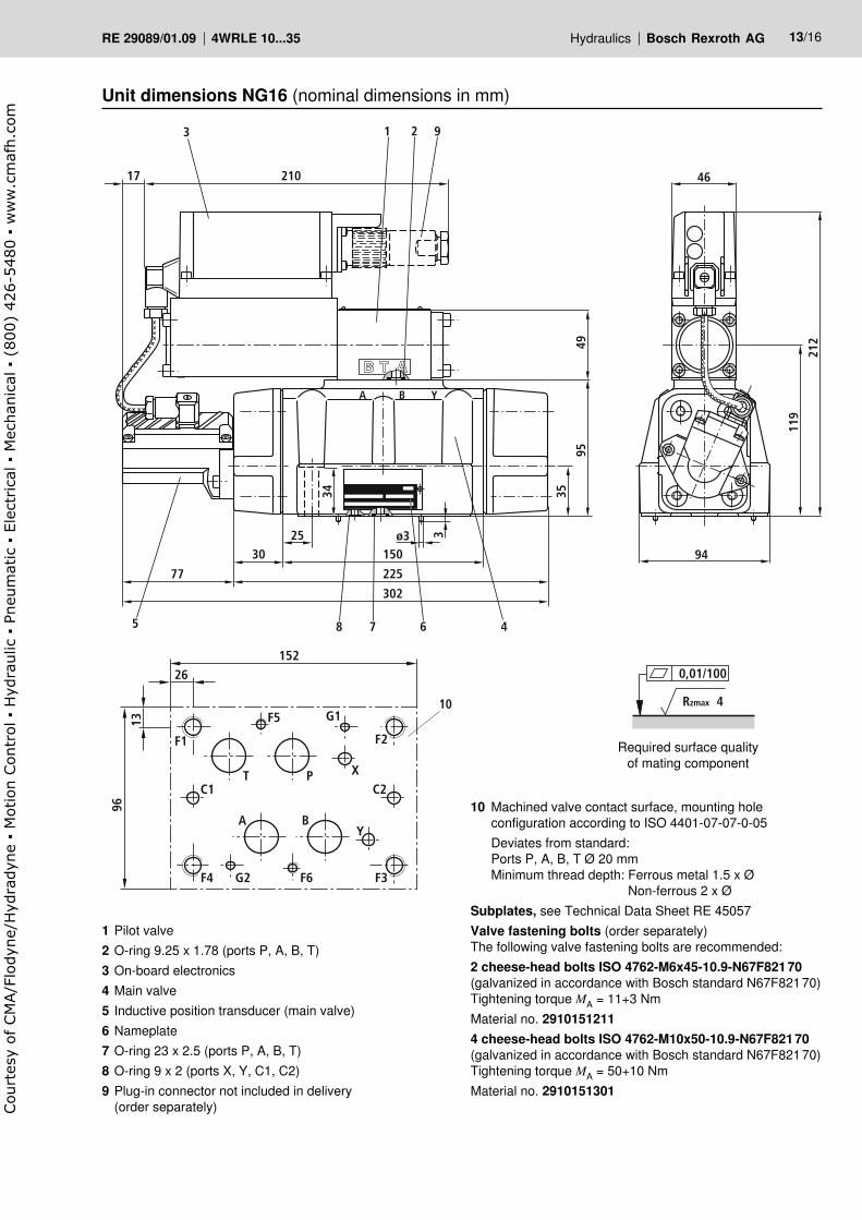
Unit dimensions NG16 (nominal dimensions in mm)
1 Pilot valve2 O-ring 9.25 x 1.78 (ports P, A, B, T)3 On-board electronics4 Main valve5 Inductive position transducer (main valve)6 Nameplate7 O-ring 23 x 2.5 (ports P, A, B, T)8 O-ring 9 x 2 (ports X, Y, C1, C2)9 Plug-in connector not included in delivery (order separately)
10 Machined valve contact surface, mounting holeconfiguration according to ISO 4401-07-07-0-05
Deviates from standard:Ports P, A, B, T Ø 20 mmMinimum thread depth: Ferrous metal 1.5 x Ø
Non-ferrous 2 x ØSubplates, see Technical Data Sheet RE 45057Valve fastening bolts (order separately)The following valve fastening bolts are recommended:2 cheese-head bolts ISO 4762-M6x45-10.9-N67F821 70(galvanized in accordance with Bosch standard N67F821 70) Tightening torque MA = 11+3 NmMaterial no. 2910151211 4 cheese-head bolts ISO 4762-M10x50-10.9-N67F821 70(galvanized in accordance with Bosch standard N67F821 70) Tightening torque MA = 50+10 NmMaterial no. 2910151301
Required surface qualityof mating component
77
5 8 7 6 4
225
302
150
A B Y
9549
3530
25
34
ø3 3
94
210
3
17
212
119
46
1 2 9
10
96
26
13
152
A B
T P
Y
C2C1X
F3F6G2F4
F2
G1
F1
F5
0,01/100
Rzmax 4
Court
esy
of CM
A/F
lodyn
e/H
ydra
dyn
e
Motion C
ontr
ol
Hyd
raulic
P
neu
mat
ic
Ele
ctrica
l
Mec
han
ical
(
800)
426-5
480
ww
w.c
maf
h.c
om
14/16 Bosch Rexroth AG Hydraulics 4WRLE 10...35 RE 29089/01.09
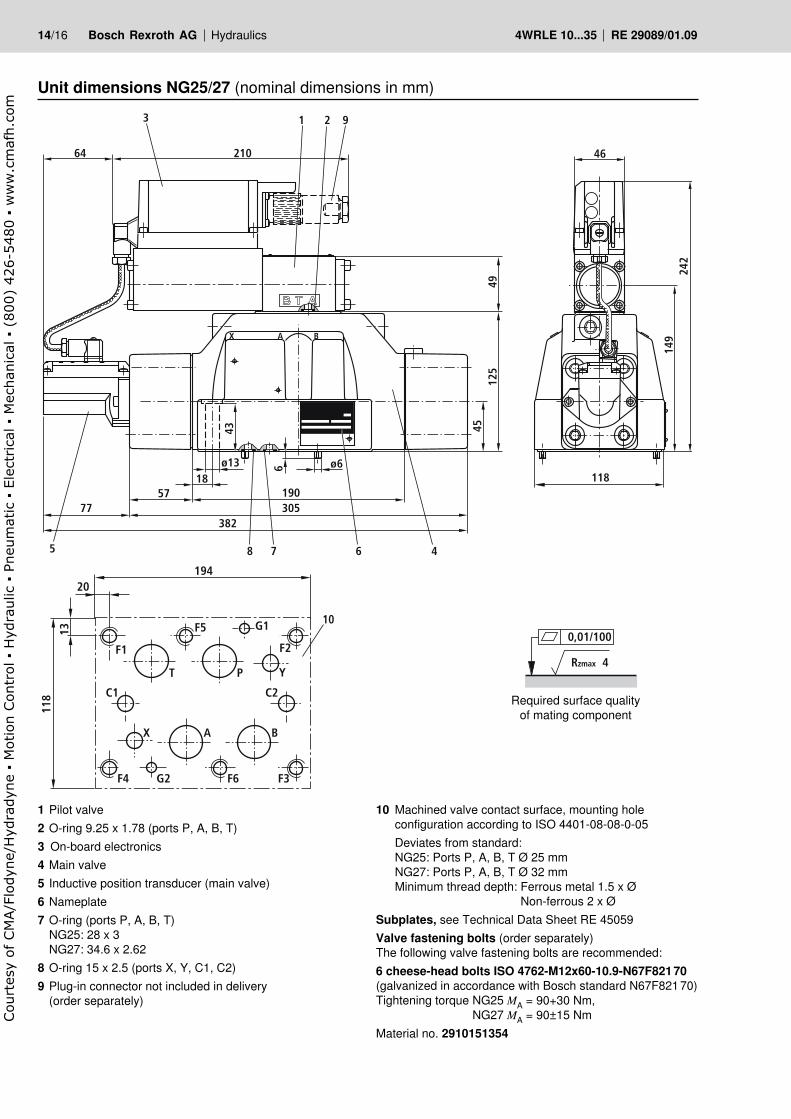
Unit dimensions NG25/27 (nominal dimensions in mm)
1 Pilot valve2 O-ring 9.25 x 1.78 (ports P, A, B, T)3 On-board electronics4 Main valve5 Inductive position transducer (main valve)6 Nameplate7 O-ring (ports P, A, B, T)
NG25: 28 x 3NG27: 34.6 x 2.62
8 O-ring 15 x 2.5 (ports X, Y, C1, C2)9 Plug-in connector not included in delivery
(order separately)
10 Machined valve contact surface, mounting holeconfiguration according to ISO 4401-08-08-0-05
Deviates from standard:NG25: Ports P, A, B, T Ø 25 mmNG27: Ports P, A, B, T Ø 32 mmMinimum thread depth: Ferrous metal 1.5 x Ø
Non-ferrous 2 x ØSubplates, see Technical Data Sheet RE 45059Valve fastening bolts (order separately)The following valve fastening bolts are recommended:6 cheese-head bolts ISO 4762-M12x60-10.9-N67F821 70(galvanized in accordance with Bosch standard N67F821 70) Tightening torque NG25 MA = 90+30 Nm,
NG27 MA = 90±15 NmMaterial no. 2910151354
Required surface qualityof mating component
210
3
64
242
149
46
1 2 9
77
5 8 7 6 4
305382
190
A BX
125
4945
5718
ø13
43
ø66
118
10
118
A BX
T P Y
C2C1
F3F6G2F4
F2
G1
F1
F5
20
13
194
0,01/100
Rzmax 4
Court
esy
of CM
A/F
lodyn
e/H
ydra
dyn
e
Motion C
ontr
ol
Hyd
raulic
P
neu
mat
ic
Ele
ctrica
l
Mec
han
ical
(
800)
426-5
480
ww
w.c
maf
h.c
om

Hydraulics Bosch Rexroth AGRE 29089/01.09 4WRLE 10...35 15/16
Unit dimensions NG35 (nominal dimensions in mm)
1 Pilot valve2 O-ring 9.25 x 1.78 (ports P, A, B, T)3 On-board electronics4 Main valve5 Inductive position transducer (main valve)6 Nameplate7 O-ring 53.57 x 3.53 (ports P, A, B, T)8 O-ring 15 x 2.5 (ports X, Y)9 Plug-in connector not included in delivery
(order separately)
10 Machined valve contact surface, mounting holeconfiguration according to ISO 4401-10-09-0-05
Deviates from standard:Ports P, A, B, T Ø 48 mmMinimum thread depth: Ferrous metal 1.5 x Ø
Non-ferrous 2 x ØSubplates, see Technical Data Sheet RE 45060Valve fastening bolts (order separately)The following valve fastening bolts are recommended:6 cheese-head bolts ISO 4762-M20x90-10.9-N67F821 70(galvanized in accordance with Bosch standard N67F821 70) Tightening torque MA = 450+110 NmMaterial no. 2910151532
Required surface qualityof mating component
77
5 8 7 6 4
458320
A BX
4929
90
69
60
5
200
225
370
ø6
43,2ø21
210
3
60
1 2 9
10
203
A BX
T P Y
F3F6G2
F4
F2G1
F1 F5
45
22
324
0,01/100
Rzmax 4
Court
esy
of CM
A/F
lodyn
e/H
ydra
dyn
e
Motion C
ontr
ol
Hyd
raulic
P
neu
mat
ic
Ele
ctrica
l
Mec
han
ical
(
800)
426-5
480
ww
w.c
maf
h.c
om

16/16 Bosch Rexroth AG Hydraulics 4WRLE 10...35 RE 29089/01.09
Bosch Rexroth AGHydraulicsZum Eisengießer 197816 Lohr am Main, GermanyTelefon +49 (0) 93 52 / 18-0Telefax +49 (0) 93 52 / 18-23 [email protected]
© This document, as well as the data, specifications and other information set forth in it, are the exclusive property of Bosch Rexroth AG. It may not be reproduced or given to third parties without its consent.The data specified above only serve to describe the product. No state- ments concerning a certain condition or suitability for a certain application can be derived from our information. The information given does not release the user from the obligation of own judgment and verification. It must be remembered that our products are subject to a natural process of wear and aging.
Notes
Court
esy
of CM
A/F
lodyn
e/H
ydra
dyn
e
Motion C
ontr
ol
Hyd
raulic
P
neu
mat
ic
Ele
ctrica
l
Mec
han
ical
(
800)
426-5
480
ww
w.c
maf
h.c
om