4/3 directional servo-valve re 29564-xn-102-b2/05.10...
TRANSCRIPT

1/12
4/3 directional servo-valvewith mechanical position feedback
Type 4WS2EM 6...XN...-102
Size 6Component series 2XMaximum operating pressure 315 barMaximum flow 48 l/min
RE 29564-XN-102-B2/05.10Replaces: 02.09
H5994
Information on explosion protection:Range of application in accordance with the Explosion Protec-tion Directive 94/9/ECII3G: Type of protection Ex nA II T5X according to
EN 60079-0:2006 / EN 60079-15:2005II3D: Type of protection Ex tD A22 IP 65 TX according to
EN 61241-0:2006 / EN 61241-1:2004
ATEX units For explosive areas
Part II Technical data sheet
What you need to know about these operating instructions These operating instructions apply to the explosion-proof version of Rexroth valves and consist of the following three parts:Part I General information RE 07010-X-B1 Part II Technical data sheet RE 29564-XN-102-B2 Part III Product-specific instructions RE 29564-XN-102-B3You can find further information on the correct handling of Rexroth hydraulic products in our publication "General product information on hydraulic products" RE 07008.
RE 29564-XN-102-B0

2/12 Bosch Rexroth AG Hydraulics 4WS2EM 6...XN...-102 RE 29564-XN-102-B2
Table of contents
Features– Directional servo-valve for proper use in explosive areas of
zone 2 and 22– Valve to control position, force, pressure or velocity – 2-stage servo valve with mechanical feedback– 1st stage as nozzle flapper plate amplifier– For subplate mounting,
porting pattern according to ISO 4401-03-02-0-05 subplates available in FE/ZN version (see page 10)
– Dry control motor, no contamination of the solenoid gaps by the hydraulic fluid
– Can also be used as 3-way version– Wear-free spool feedback element– Control:
External control electronics in Eurocard format or in modu-lar design (separate order), see page 6
– Valve is adjusted and tested– Pressure chambers at the control sleeve with gap seal,
therefore no wear of the seal ring– Filter for 1st stage freely accessible from the outside
Content PageFeatures 2Ordering code and scope of delivery 3Symbol 3Function, section 4Technical data 5, 6Information on explosion protection 6External control electronics 6Mating connector 7Electrical connection 7Characteristic curves 8, 9Unit dimensions 10Flushing plate 11

A B
TP
a, b
Hydraulics Bosch Rexroth AGRE 29564-XN-102-B2 4WS2EM 6...XN...-102 3/12
Ordering code and scope of delivery
Symbol
Included in the delivery:Valve operating instructions with declaration of conformity in part III
1) Rated flow The rated flow refers to a 100% command value signal
at 70 bar valve pressure differential (35 bar per control edge). The valve pressure differential must be regarded as reference. Other values result in the flow being changed. A possible rated flow tolerance of ±10% must be taken into account (see flow signal function page 8).
2) External control electronics The actuating signal must be formed by a current controlled
output stage. Control electronics (servo amplifier) see page 6.3) Pilot oil The valve is only delivered with internal pilot oil supply
and return.
4) Inlet pressure range Care should be taken that the system pressure is as con-
stant as possible. With regard to the dynamics, the frequency response de-
pendency must be observed within the admissible pressure range of 10 ... 210 bar and/or 10 ...315 bar.
5) Spool overlap The spool overlap is specified in % of the control spool
stroke.6) Special number "102" Without actuation (de-energized condition), channels P → A
and B → T are open for 10% of the nominal quantity.
102 = special number 6)
Seal material V = FKM seals,suitable for mineral oil (HL, HLP)
according to DIN 51524 Spool overlap 5)
E = 0 … 0.5 % negativeD = 0 … 0.5 % positiveC = 3 … 5 % positive
K17 = electrical connectionvia connector
Order mating connector separately, see page 7
Inlet pressure range 4)
210 = 10 to 210 bar315 = 10 to 315 bar
ET = internal pilot oil supply and return3)
XN = explosion protection "type nA“For details see information on the explosion protection, page 6
4WS2EM 6 2X B 11 XN ET K17 V 102
Electrically actuated 2-stage servo valve in 4/3 directional design with mechanical feedback for external control electronicsSize 6 = 6Component series 20 to 29 = 2X(20 to 29: unchanged installation and connection dimensions)Rated flow 1)
2 l/min = 25 l/min = 510 l/min = 1015 l/min = 1520 l/min = 2025 l/min = 25Characteristic curves, see page 8 (observe tolerance field of flowsignal function)Valve for external control electronics = 11coil no. 11 (30 mA/85 Ω per coil) 2)

A B(T)P
6
3
2
4
5
1
9
8
7
4/12 Bosch Rexroth AG Hydraulics 4WS2EM 6...XN...-102 RE 29564-XN-102-B2
Function, section
4WS2EM 6-2X/...XN...-102Valves of this type are electrically actuated, 2-stage directional servo-valves with porting pattern according to ISO 4401-03-02-0-05. They are mainly used to control posi-tion, force, pressure or velocity.These valves are made of an electro-mechanical converter (torque motor) (1), a hydraulic amplifier (principle: nozzle flap-per plate) (2) and a control spool (3) in a bushing (2nd stage) which is connected with the torque motor via a mechanical feedback.An electrical input signal at the coils (4) of the torque motor generates a force by means of a permanent magnet which acts on the armature (5), and in connection with a torque tube (6) results in a torque. This causes the flapper plate (7) which is connected to the torque tube (6) via a pin to move from the central position between the two control nozzles (8), and a pressure differential is created across the front faces of the control spool (3). The pressure differential results in the spool changing its position, which results in the pressure port be-ing connected to one actuator port and, at the same time, the other actuator port being connected to the return flow port.
The control spool is connected to the flapper plate or the torque motor by means of a bending spring (mechanical feed-back) (9). The position of the spool is changed until the feed-back torque across the bending spring and the electro-mag-netic torque of the torque motor are balanced and the pres-sure differential at the nozzle flapper plate system becomes zero.The stroke of the control spool and consequently the flow of the servo valve are controlled in proportion to the electrical in-put signal. It must be noted that the flow depends on the valve pressure drop.
External control electronics (separate order)External control electronics (servo amplifier) serve the actua-tion of the valve, amplifying an analog input signal (command value) so that with the output signal, the servo valve is actu-ated in a flow-controlled form.
Type 4WS2EM 6-2X/...XN...-102

Hydraulics Bosch Rexroth AGRE 29564-XN-102-B2 4WS2EM 6...XN...-102 5/12
Technical data
generalPorting pattern ISO 4401-03-02-0-05Installation position Any (Ensure that upon system start-up, the valve is
supplied with enough pressure (≥10 bar)! )Surface protection Valve body, cover, filter screw Nitro-carburated
Cap AnodizedStorage temperature range °C –20 … +80Ambient temperature range °C –30 … +80 Weight kg 1.1
hydraulic (measured with HLP 32, ϑoil = 40°C ±5°C)Operating pressure Ports P, A, B bar 10 … 210 or 10 … 315Return flow pressure Port T bar Pressure peaks < 100, static < 10Hydraulic fluid Mineral oil (HL, HLP) according to DIN 51524,
ignition temperature > 150 °CHydraulic fluid temperature range °C -15 ... +80; preferably +40 ... +50Viscosity range mm2/s 15 ... 380; preferably 30 ... 45Maximum admissible degree of contamination of the hydrau-lic fluid cleanliness class according to ISO 4406 (c) Class 18/16/131)
Zero flow qV,L 2) with spool overlap Emeasured without dither signal
l/min √ pP / 70 bar • (0.4 l/min + 0.02 • qV rated) 3); 4)
Rated flows qv rated 3), tolerance ±10 % with valve pressure differential Δp = 70 bar
l/min 2; 5; 10; 15; 20; 25
Max. control spool stroke possible with mechanical end position (in case of error) related to nominal stroke
% 120 … 170
Feedback system MechanicalHysteresis (dither-optimized) % ≤ 1.5Range of inversion (dither-optimized) % ≤ 0.2Response sensitivity (dither-optimized) % ≤ 0.2Pressure gain with 1 % spool stroke change(from the hydraulic zero point)
% of pP 4) ≥ 50
Zero adjustment flow over the entireoperating pressure range
% ≤ 3, long-term ≤ 5
Zero shift upon change of:Hydraulic fluid temperature % / 20 ≤ 1Ambient temperature % / 20 ≤ 1Operating pressure 80 … 120 % of pP
4) % / 100 bar ≤ 2Return flow pressure 0 … 10 % of pP
4) % / bar ≤ 1
1) The cleanliness classes specified for the components must be adhered to in hydraulic systems. Effective filtration pre-vents faults and at the same time increases the service life of the components.
For the selection of filters, see technical data sheets RE 50070, RE 50076 and RE 50081.
2) qV,L = Zero flow in l/min3) qv rated = Rated flow in l/min4) pP = Operating pressure in bar

6/12 Bosch Rexroth AG Hydraulics 4WS2EM 6...XN...-102 RE 29564-XN-102-B2
electricProtection class according to EN 60529:1991+A1:2000 IP 65 with mating connector correctly mounted and lockedType of signal analogRated current per coil mA 30Resistance per coil Ω 85
Inductivity with 60 Hzand 100% rated current
Connection in series H 1.0Connection in parallel H 0.25
In case of actuation using non-Rexroth amplifiers, we recommend a superimposed dither signal
Technical data
Range of application as per directive 94/9/EC II 3 G; II 3 DType of protection according to EN 60079-0:2006 / EN 60079-15:2005
Ex nA II T5X
Type of protection according to EN 61241-0:2006 / EN 61241-1:2004
Ex tD A22 IP 65 TX
Maximum surface temperature °C 100Ambient temperature range °C –30 … +80Hydraulic fluid temperature range °C –15 … +80Max. admissible operating voltage of the servo amplifier V 32 (DC)Conditions for use in zone 2 and 22 The valve may only be used in explosive zones of device
group II, category 3, with "low" risk of mechanical hazards according to the harmonized standards EN 60079-0:2006, section 26.4.2 and EN 61241-0:2006, section 23.4.2.1.If used in zones with a "high" risk of mechanical load accord-ing to these standards , the user must take measures with a "low" risk of mechanical load.
Servo amplifier (separate order)
Eurocard format Analog Type VT-SR2-1X/.60 according to technical data sheet RE 29980
Modular design Analog Type VT 11021 according to technical data sheet RE 29743The coils of the valve may only be connected to these amplifiers in parallel!
WARNING – Risk of explosion – The external servo amplifier must be operated outside the explosive area!
Information on explosion protection
External control electronics

Ø21
,6
58
Ø4,
5...
Ø7,
0
A
B
C
DEF
A B
Hydraulics Bosch Rexroth AGRE 29564-XN-102-B2 4WS2EM 6...XN...-102 7/12
Electrical connection (example of parallel connection)
Mating connector
Lock screw
The servo valve may only be supplied through this mating connector. Separate order, material no. R901043330
Valve: Coils
Mating connectorControl electronics
Non-explosive area Explosive area The coils are connected in parallel in the mating connector or at the amplifier (see figure). In case of serial connection, contacts B and C must be connected.The E-F bridge can be used for the electrical determination of the correct connection of the plug-in connector and/or for the identification of cable break.The electrical actuation from A (+) to D (–) causes flow di-rection from P → A and B → T. The reverse electrical actua-tion causes flow direction from P → B and A → T.
Connection:Contact bushings with connection cross-section for litz wires 0.4 … 0.75 mm2 are supplied unpacked.The connection of the litz wires to the contact bush-ings is possible by crimping or soldering.A list of the required tools for crimping connection is available in the assembly instructions which are sup-plied with the mating connector.

100
60
80
20
40
20
60
40
100
80
–20–40–60–80
4020 60 80
110
–100
100
110
–10
20 30 40 50 80 100 200 300
5040
30
20
15
108
654
3
2
160
1
2
3
4
5
70
6
25
8/12 Bosch Rexroth AG Hydraulics 4WS2EM 6...XN...-102 RE 29564-XN-102-B2
Characteristic curves (measured with HLP 32, ϑoil = 40°C ±5°C)
Valve pressure differential in bar →
Flow
in l/
min
→
Δp = Valve pressure differential (inlet pressure pP minus load pressure pL minus return flow pressure pT)
Tolerance field of flow/signal functionat constant valve pressure difference Δp
Ordering code
Rated flow Curve
2 2 l/min 15 5 l/min 2
10 10 l/min 315 15 l/min 420 20 l/min 525 25 l/min 6
P → A; B → T
P → B; A → T
Flow in %
Command value in %Typical flow curve
Tolerance field
Flow/load function (tolerance ±10 %) with 100 % command value signalNote:Observe flow values in the max. command value range (see tolerance field of the flow/signal function)

–30
–25
–20
–15
–10
–5
0
5
10 100 10000
–45
–90
–135
–180
–225
–270
–315
50 50020 20030 300
±5 %
±25 %
±100 %–3
100 150 200 250 300 3500
100
90
80
70
60
50
40
30
20
10
40 bar
70 bar
140 bar
210 bar
315 bar
100
80
60
40
20
02 4 6 8 10 12
40 bar
70 bar
140 bar
210 bar
315 bar
Hydraulics Bosch Rexroth AGRE 29564-XN-102-B2 4WS2EM 6...XN...-102 9/12
Characteristic curves (measured with HLP 32, ϑoil = 40°C ±5°C)
Transition function with pressure rating 315 bar, step response without flow
Frequency response with pressure rating 315 bar, stroke frequency without flow
Spoo
l stro
ke in
% →
Time in ms →
Ampl
itude
ratio
in d
B→
Frequency in Hz →
Dependency of the frequency f at –90 ° on the operating pressure p and the inlet amplitude
Inle
t am
plitu
de in
% →
Frequency with phase angle –90 ° in Hz 1) →
Phas
e an
gle
in °
→
1) Correction factors at q V rated: 25 l/min 1.00 20 l/min 1.00 15 l/min 0.95 10 l/min 0.90 5 l/min 0.85 2 l/min 0.80
The output signal corre-sponds to the spool stroke with flow and without load pressure
Measured at pilot pressure pST = 315 bar

B
52,5 64
M5
58
4535
808
2
4
A P(T)
3
A
BP
T
8066
40,57 14
137
0,75
462
31
Ø4,
5…7,
0
151
6 7
31,7
5
5 8 9
10/12 Bosch Rexroth AG Hydraulics 4WS2EM 6...XN...-102 RE 29564-XN-102-B2
Unit dimensions (dimensions in mm)
0,01/100
Rzmax 4
Required surface quality of the valve mounting face
1 Required space for the removal of mat-ing connectors, additionally observe the bending radius of the connection line
2 Cap3 Valve mounting screws
For reasons of stability, exclusively the following valve mounting screws may be used:4 hexagon socket head cap screwsISO 4762-M5x50-10.9-flZn-240h-L(Friction coefficient 0.09 – 0.14 according to VDA 235-101)(included in the delivery)
4 Identical seal rings for ports P, A, B and T
5 Name plate6 Mating connector (order separately,
see page 7)7 Connection line, further
information on page 7
8 Filter9 Plug screw
10 Machined valve mounting face,porting pattern according to ISO 4401-03-02-0-05 Deviating from the standard:
– Locating pin not available (G)
Subplates G341/01 FE/ZN (G1/4)G342/01 FE/ZN (G3/8)G502/01 FE/ZN (G1/2)with dimensions as in the technical data sheet RE 45052(must be ordered separately)
Note:Subplates are no components in the sense of directive 94/9/EC and can be used after the manufacturer of the overall system has assessed the risk of ignition.The G...FE/ZN versions are free from aluminum and/or magnesium and galva-nized.
F1
F3F4
F2
G
T
P BA
8019
478
10

30,5 35
,59,
5
Hydraulics Bosch Rexroth AGRE 29564-XN-102-B2 4WS2EM 6...XN...-102 11/12
Flushing plate with porting pattern according to ISO 4401-03-02-0-05 (dimensions in mm)
A BP T
Symbol
Ordering code and more information– Material number: R900936049– Weight: 0.6 kg– Identical seal rings for ports P, A, B and T– Mounting screws
For reasons of stability, exclusively the followingmounting screws may be used:4 hexagon socket head cap screws ISO 4762-M5x40-10.9-flZn-240h-L(Friction coefficient 0.09 - 0.14 according to VDA 235-101) (included in the delivery)
NoteBefore the assembly, observe the information in the product-specific instructions RE 29564-XN-102-B3, section 3.2.

Bosch Rexroth AGHydraulicsZum Eisengießer 197816 Lohr am Main, GermanyPhone +49 (0) 93 52 / 18-0Fax +49 (0) 93 52 / 18-23 [email protected]
© This document, as well as the data, specifications and other informati-on set forth in it, are the exclusive property of Bosch Rexroth AG. It may not be reproduced or given to third parties without its consent. The data specified above only serve to describe the product. No state-ments concerning a certain condition or suitability for a certain applica-tion can be derived from our information. The information given does not release the user from the obligation of own judgment and verification. It must be remembered that our products are subject to a natural process of wear and aging.
12/12 Bosch Rexroth AG Hydraulics 4WS2EM 6...XN...-102 RE 29564-XN-102-B2
Notes

1/4Declaration on environmental com-patibility in the field of EMC1),climate and mechanical stress
Type 4WSE2EM10-5X/, 4WSE2ED10-5X/
Directional servo-valve of 4-way design
RE 29583-U/11.09
Description of the product family
1) as defined by EMC dated 30th August 1995 and Directive 89/336/EEC
Produkt typs– 4WSE2EM 10...5X according to data sheet RE 29583– 4WSE2ED 10...5X according to data sheet RE 29583
– Valve for the closed-loop control of position, force and speed control
– 2-stage servo-valve with mechanical or mechanical and elec-trical feedback
– Electronics external or integrated into the valve

2/4 Bosch Rexroth AG Hydraulics 4WSE2EM10-5X/, 4WSE2ED10-5X/ RE 29583-U/11.09
The above products comply with the following standards:
1. EMC (electromagnetic compatibility)
Testing according to specialized basic standard prEN 50082-2:1996, VDE 0839 part 82-2, Interference immunity
EN 61000-4-2:1995 IEC 1000-4-2
VDE 0847-4-2 ESD (electrostatic discharge)
Air discharge: Severity 1 / Assessment criterion A Severity 4 / Assessment criterion BContact discharge: Severity 4 / Assessment criterion B
EN 61000-4-4:1995 VDE 0847-4-4 BURST (transient discharge)
Supply voltage: Severity 3 / Assessment criterion BData cable: Severity 4 / Assessment criterion B
Measuring setup according to prEN 61000-4-2 und prEN 61000-4-4
2. Climate
Testing according to EN 60068-2 / IEC 68-2 (Environmental test)
EN 60068-2-1:1994EN 60068-2-2:1993
Storage temperature –25 °C, dwell time 16 hours +85 °C, dwell time 16 hours
IEC 68-2-14:1986 Temperature cycles 2 cycles –25 °C to +70 °CDwell time je 3 hours at min. / max. Temperatur
IEC 68-2-30:1985 Damp heat, cyclical Variant 2 +25 °C to +55 °C 95 % to 97 % relative humidity2 Cycles á 24 hours
3. Mechanical stress
Vibration and shock test according to EN 60068-2 / IEC 68-2 (Environmental test) Tests were carried out in three axes (X/Y/Z)
prEN 60068-2-6:1994 Vibration, sinusoidal
10 cycles, 5…2000 Hz…5 Hz at a logarithmic frequency change rate of 1 Oct./Min.5 to 57 Hz, amplitude 1,5 mm (p-p) 57 to 2000 Hz, amplitude 10 g Dwell time per axis: 30 min at resonance frequency
IEC 68-2-36:1973 DIN 40046-24:1977
Random vibrationBroadband noise
20 to 2000 Hz, amplitude 0,05 g2/Hz (10 g RMS) testing time 30 min per axis
EN 60068-2-27:1993 Shock Half sine 15 g / 11 ms, 3 x in positive / 3 x in negative direction per axis, in total 18 individual shocks

Hydraulics Bosch Rexroth AGRE 29583-U/11.09 4WSE2EM10-5X/, 4WSE2ED10-5X/ 3/4
notes

Bosch Rexroth AG HydraulicsZum Eisengießer 197816 Lohr am Main, Germany Telefon +49 (0) 93 52 / 18-0 Telefax +49 (0) 93 52 / 18-23 [email protected] www.boschrexroth.de
© This document, as well as the data, specifications and other informati-on set forth in it, are the exclusive property of Bosch Rexroth AG. It may not be reproduced or given to third parties without its consent.The data specified above only serve to describe the product. No state-ments concerning a certain condition or suitability for a certain applicati-on can be derived from our information. The information given does notrelease the user from the obligation of own judgment and verification. Itmust be remembered that our products are subject to a natural process of wear and aging.
4/4 Bosch Rexroth AG Hydraulics 4WSE2EM10-5X/, 4WSE2ED10-5X/ RE 29583-U/11.09
notes

© 2002by Bosch Rexroth AG, Industrial Hydraulics, D-97813 Lohr am Main
All rights reserved. No part of this document may be reproduced or stored, processed, duplicated or circulated usingelectronic systems, in any form or by any means, without the prior written authorisation of Bosch Rexroth AG.In the event of contravention of the above provisions, the contravening party is obliged to pay compensation.
This document was prepared with the greatest of care, and all statements have been examined for correctness.This document is subject to alterations for reason of the continuing further developments of products.No liability can be accepted for any incorrect or incomplete statements.
4WS.2E… 1/16 RE 29 591/06.02
Overview of contents
Contents Page
Features 1
Ordering details, preferred types 2 and 3
Symbols 3
Test unit 3
Function, section 4 and 5
Technical data 6 and 7
Control electronics 7
Plug-in connectors, electrical connections 8
Characteristic curves 9 to 13
Unit dimensions, subplates 14 and 15
Pilot oil supply and drain, flushing 16
RE 29 591/06.02
Replaces: 03.93
4-way directional servo valveType 4WS.2E…
Nominal size 16Series 2XMaximum operating pressure 210/315 barMaximum flow 320 L/min
Type 4WSE2ED 16-2X/…B… with mechanical and electricalfeedback and integrated control electronics
H/A
3013
Features
– Valve for closed loop position, force and speed control
– Two stage servo valve with mechanical or mechanical andelectrical feedback
– 1st stage as an orifice-flapper plate amplifier
– For subplate mounting, porting pattern to DIN 24 340 form A16with port X, subplates to catalogue sheet RE 45 054 (separateorder)
– Dry torque motor, no contamination of the solenoid gap by thepressure fluid
– Can also be used as a 3-way version
– Wear-free spool return element
– Three control variations
– Control:• External control electronics in eurocard format (separate
order), see page 7• Or with the control electronics integrated into the valve
– The valves with integrated control electronics are calibrated andtested
– The pilot oil supply, internal/external, can be changed withoutdismantling the valve
– The control sleeve can be replaced
– Filter for the 1st stage is accessible from the outside by meansof a plug
Type 4WS2EM 16-2X/…B… with mechanical feedback andassociated external control electronics (separate order)
H/A/
3012

RE 29 591/06.02 2/16 4WS.2E…
1
2
3
7
6
5
4
2
1
3
4
5
6
7
Input pressure rangeThe system pressure must be maintained as constant as possible.
Pilot pressure range: 10 to 210 bar or 10 to 315 bar
With referance to the dynamics, within the permissible pressure rangethe frequency relationship must be taken into account.
Spool overlap
The spool overlap in % refers to the control spool nominal stroke.
Other spool overlaps on request!
Seal material
If other seal materials are required please consult us!
Details in clear text
Special requirments are to be specified in clear text. After receipt ofthe order they will be checked by the factory and the type code willbe completed with an associated number.
Electrically operated2-stage4-way servo valve
For external = 4WS2Econtrol electronics
With integrated = 4WSE2Econtrol electronics
Mechanical feedback = M
Mechanical and = Delectrical feedback(only with integrated electronics)
Nominal size 16 = 16
Series 20 to 29 = 2X(20 to 29: unchanged installation and connection dimensions)
Nominal flowAt a valve pressure differential ∆p = 70 bar100 L/min = 100150 L/min = 150200 L/min = 200(the tolerance of the flow/signal functionon page 9 has to be taken into account!)
Coil or control dataValves for external control electronicsCoil No. 12 (50 mA/85 Ω per coil) = 12Valves with integrated electronicsControl: Command value ± 10 mA/1 kΩ = 8
Command value ± 10 V/≥ 50 kΩ = 9
Further detailsin clear text
V = FKM seals
Spool overlap
E = 0 to 0.5 % negative
Electrical connectionValve for external control electronics:
K8 = Without plug-in connectorwith component plug for a 4-pinplug-in connector to VG 095 342
Valve with integrated control electronics:K9 = Without plug-in connector
with component plug for a 6-pinplug-in connector to E DIN 43 563-AM6-3
Plug-in connector – separate order
Input pressure range for the 1st stage
210 = 10 to 210 bar315 = 10 to 315 bar
Pilot oil supply and drainET = Internal supply and drain (standard)T = External supply, internal drain
16 –2X / B E V *
Nominal flowThe nominal flow refers to a 100 % command value signal at a 70bar valve pressure differential (35 bar per control land). This valvepressure differential is to be considered as a reference value. Othervalues cause a change in the flow.Please take into account a possible nominal flow tolerance of± 10 % (see flow/load function on page 9).
Electrical control dataValves for external control electronics: The positioning signal mustbe generated by a current regulated output stage. See page 7 forservo amplifiers.Valves with integrated control electronics: The command value canbe applied as a voltage (ordering detail „9“) or for longer distances(> 25 m between the control and the valve) as a current (orderingdetail „8“).
Input pressure for the pilot controlThe pilot pressure must be maintained as constant as possible.Therefore an external pilot control via port X is often advantageous.
The dynamic response of the valve may be influenced using a higherpressure at X than at P.
Ordering details

4WS.2E… 3/16 RE 29 591/06.02
A
P T
a, b
B
a, b
BA
P T
a, b
BA
P T
A
P T
a, b
B
Test unit (battery operated, optionally with a power supply) tocatalogue sheet RE 29 681Attention:– Only for valves with external control electronics
Test unit for proportional and servo valves with integratedcontrol electronicsType VT-VET-1, series 1X to catalogue sheet RE 29 685.
The test unit is used for the control and functional testing of propor-tional and servo valves with integrated electronics. It is suitable fortesting valves with an operating voltage of ± 15 V or 24 V.The following operating modes are possible:– External operation → Linking the operating voltage and the
command value from the control cabinet to the valve– Internal/external operation → Command value is applied by the
test unit; the operating voltage via the control cabinet– Internal operation → Operating voltage via a seperate power
supply; the command value is applied by the test unit– Command value is applied via a BNC socket → Optional operating
voltage
Symbols
Mechanical feedback Electrical and mechanical feedback
Valves with integrated control electronicsValves for external control electronics
Preferred types (readily available)
Valves for external control electronics,mechanical feedback
Material No. Type 4WS2EM
00769978 4WS2EM 16-2X/100B12ET315K8EV00716550 4WS2EM 16-2X/150B12ET315K8EV00960575 4WS2EM 16-2X/200B12ET315K8EV
Valves with integrated control electronics,mechanical and electrical feedback
Material No. Type 4WSE2ED00769983 4WSE2ED 16-2X/100B9ET315K9EV00769982 4WSE2ED 16-2X/150B9ET315K9EV00769984 4WSE2ED 16-2X/200B9ET315K9EV
Material No Type 4WSE2EM
00769976 4WSE2EM 16-2X/100B9ET315K9EV00769980 4WSE2EM 16-2X/150B9ET315K9EV00769981 4WSE2EM 16-2X/200B9ET315K9EV
Valves with integrated control electronics,mechanical feedback
Detailed
Simplified
Test unit

RE 29 591/06.02 4/16 4WS.2E…
B PA T X
3
2
1
9
7 8
4
5
6
Function, section
Type 4WS2EM 16 …
4WS(E)2EM 16-2X/...The valve types 4WS(E)2EM... are electrically actuated, 2-stage servodirectional valves with a porting pattern to DIN 24 340 form A16.They are primarily used for the closed loop control of position, forceand velocity.These valves comprise of an electro-mechanical convertor (torquemotor) (1), a hydraulic amplifier (flapper jet principle) (2) and a controlspool (3) in a sleeve (2nd stage), that is connected to the torquemotor via a mechanical feedback.Via an electrical input signal at the coils (4) of the torque motor, aforce is generated via a permanent magnet at the armature (5) that,in conjunction with a torque tube, (6) generates a torque. Due to thisthe flapper plate (7), which is connected with the torque tube (6) viaa rod, is moved out of the central position between the control orifices(8) a pressure differential now results which acts on the front face ofthe control spool. This pressure differential causes the spool to move,whereby the pressure connection is connected to an actuatorconnection and at the same time the other actuator connection isconnected to the return connection.The control spool is connected via a feedback spring (mechanicalfeedback) (9) to the flapper plate and torque motor. The control spoolcontinues to change position until the torque feedback, via thefeedback spring and the electro-magnetic torque of the torque motorare balanced, and the pressure differential at the flapper jet systembecomes zero.The stroke of the control spool and thus the flow through the pilotcontrol valve is closed loop controlled in proportion to the electricalinput signal. It has, however to be taken into account that the flow isdependent on the valve pressure differential.
External control electronics, type 4WS2EM 16-2X/...(separate order)
External control electronics, (servo amplifier), are used to control thevalve, they so amplifiy the analogue input signal (command value)that the controlled current output signal is capable of driving thevalve.
Integrated control electronics, types 4WSE2EM16-2X/... and4WSE2ED 16-2X/...
For the amplification of the analogue input signal control electronics(10), which are specially matched to the valve, are integrated intothe valve. They are built into the torque motor cover plate. The valvezero point can be adjusted by a potentiometer which is externallyaccessible.
4WSE2ED 16-2X/...This type of valve is fitted with, in addition to the mechanical closedloop control via a feedback spring, an electrical spool positionacquisition and control system. The spool position is obtained via aninductive position transducer (11). The position transducer signal iscompared with the command value via the integrated controlelectronics (10). Any possible control deviation is electrically amplifiedand then passed onto the torque motor as a control signal. With theadditional electrical feedback it is possible to obtain higher dynamicvalues in the small signal range than the purely mechanical versiondue to the electrical closed loop amplification. The mechanicalfeedback ensures that, in the case of failure of the electrical powersupply, the spool is positioned in the zero range.The valve is only available with integrated control electronics. Thevalve zero point can be adjusted by an externally accessiblepotentiometer.

4WS.2E… 5/16 RE 29 591/06.02
10
11
B PA T X
B PA T X
10
Type 4WSE2EM 16…
Type 4WSE2ED 16…
Section

RE 29 591/06.02 6/16 4WS.2E…
p
70
Technical data (for applications outside these applications, please consult us!)
General
Porting pattern DIN 24 340 form A16
Installation Optional, it has however to be ensured that, when the system isstarted, the pilot control is supplied with an adequate pressure ( ≥10 bar)!
Storage temperature range °C –20 to +80
Ambient temperature range °C –30 to +70, valve for external control electronics
–20 to +60, valve with integrated control electronics
Weight With mechanical feedback kg 10.0With mechanical and electrical feedback kg 11.0and integrated control electronics
Hydraulic (measured with a viscosity of ν = 32 mm2/s and ϑ = 40 °C)
Operating pressure (ports A, B, P, X) bar 10 to 210 or 10 to 315
Return pressure, port T bar Pressure peaks < 100, static < 10
Pressure fluid Mineral oil (HL, HLP) to DIN 51 524,other pressure fluids on request!
Pressure fluid temperature range °C –20 to +80; preferably +40 to +50
Viscosity range mm2/s 15 to 380; preferably 30 to 45
Degree of contamination Maximum permissible A filter with a minimum retention ratedegree of of βX ≥ 75 is recommended without
contamination of the bypass valve and fitted as close aspressure fluid possible in front of the servo valve
Class 7 x = 5
Zero flow qV,L1) (spool overlap “E”)
measured without a dither signal L/min ≤ • 3.5 L/min 2)
Nominal flow qV nom ± 10 % 3)
at a valve pressure differential ∆p = 70 bar 4) L/min 100 150 200
Pressure gain (spool overlap „E“)at 1% change in stroke (starting from the hyd. zero point) % von p ≥ 65 ≥ 80 ≥ 90
Control spool stroke mm 0.6 0.9 1.2
Control spool area mm2 78
Feedback system Mechanical (M) Mechanical and electrical (D)
Hysteresis (dither optimised) % ≤ 1.5 ≤ 0.5
Reversal range (dither optimised) % ≤ 0.3 ≤ 0.2
Response sensitivity (dither optimised) % ≤ 0.2 ≤ 0.1
Zero balance in % von Inom ≤ 3 ≤ 2
Zero offset at change in:
Pressure fluid temperature %/20 °K ≤ 1.5 ≤ 1.2
Ambient temperature %/20 °K ≤ 1 ≤ 0.5
Operating pressure %/100 bar ≤ 2 ≤ 1
Return pressure 0 to 10 % of p % ≤ 1 ≤ 0.5
1) qV,L = Zero flow in L/min2) p = Operating pressure in bar
3) qV nom = Nominal flow (complete valve) in L/min4) ∆p = Valve pressure differential in bar

4WS.2E… 7/16 RE 29 591/06.02
A DB
60
104SW
20
Ø28
Ø6,
5…Ø
9,5
C
Technical data (for applications outside these parameters, please consult us!)Electrical
Feedback system Mechanical (M) Mechanical and electrical (D)
Valve protection to EN 60 529 IP65
Signal type Analogue
Nominal current per coil mA 50 –
Resistance per coil Ω 85 –
Inductivity at 60 Hz and 100% nominal current:Series circuit H 0.96 –
Parallel circuit H 0.24 –
Recommended The amplitude value is dependent on the hydraulic system:dither signal: f = 400 Hz a max. 5 % vom of the nominal current
Electrical, external control electronics
Amplifier in (separate order) eurocard format Type VT-SR2, to catalogue sheet RE 29 980
Note: For details regarding the environmental simulation test covering EMC (electro-magnetic compatibility), climateand mechanical loading see RE 29 591-U (declaration regarding environmental compatibility).
Coil electrical connections in the component plug (for valves with external control electronics)The electrical connections can be either in parallel or series. Due tooperational safety considerations and the low spool inductivity, werecommend a parallel circuit.
BlueRed
B AC D
4 WS 2 EM 16-2X/...
Parallel circuit: In the plug connect contacts A with B and Cwith D.
Series circuit: In the plug connect contacts B with C.
Electrical control from A (+) to D (–) results in a flow direction fromP to A and B to T. Reversed electrical control results in a flow directionof P to B and A to T.
Connection cable:4-core, 0.75 mm2, screened (e.g. cable type LiYCY 4x0.75mm2)Outside diameter 6.5 to 9.5 mmOnly connect the screen to the supply side.
BlueRed
Plug-in connector
Plug-in connector version K9 to E DIN 43 563-BF6-3/Pg11separate order under Material No. 00223890(metal version)
Plug-in connector version K8 (external control electronics) toVG 095 342 – separate order under Material No. 00002460
AB
CD
E
F
Ø8…
Ø13
,5
85
20A
/F20
A/F

RE 29 591/06.02 8/16 4WS.2E…
Terminal connections 4 WSE2E .16. (valves with integrated control electronics)
Supply voltage: ± 15 V ± 3 %, residual ripple < 1 %
Command value: A command value at plug connection D = negative with respect to the plug connection Eresults in a flow from P to B and A to T.
Measurement output F has a negative signal with respect to .
A command value at plug connection D = positive with respect to the plug connection Eresults in a flow from P to A and B to T.
Measurement output F has a positive signal with respect to .
Measurement output: The voltage signal UF is proportional to the spool stroke.
A
B
C
D
E
F
Re
Ri
Integratedcontrol electronics
1) For valves without electrical feedback terminal F is not connected.
Zero point adjustment
Note: Electrical signals (e. g. actual value) taken via valve electronics must not be used to switch offthe machine safety functions!
(Also see European standard "Safety requirements of fluid technology systems and components– hydraulics", prEN 982 !)
Current Voltageinput signal input signalControl “8” Control “9”
+ 15 V + 15 V– 15 V – 15 V
± 10 mA; ± 10 VRe = 1 kΩ Re ≥ 50 kΩ
Nom. stroke corresponds to approx. ± 10 Vwith respect to ; Ri = 1 kΩ
Max. 150 mA Max. 150 mA
± 10 mA ≤ 0.2 mA
Terminal connections Supply A
voltage B(± 3 %) CCommand value D
E
Measuring output F 1)
for the control spool
Current Aconsumption at Bplug terminal D
E

4WS.2E… 9/16 RE 29 591/06.02
20 40 60 80
–40–60–8020
40
60
80
100
80
60
40
20
100
–20
P B; A T
–100
P A; B T
110
110
100
Characteristic curves (measured with HLP32, ϑ oil = 40 °C ± 5 °C)
Flow/load function (tolerance ± 10 %)
at 100 % command value signal
Tolerance range of flow/signal function
at constant valve pressue differential
Flow
in L
/min
→
Valve pressure differential in bar →
∆p = Valve pressure differential(input pressure minus thereturn pressure and minusthe load pressure)
Flow in %
Command valuein %
Passes through zerodependent on spooloverlap
Typical flowcurve
Tolerance range
500
400
300
200
150
100
70
50
40
30
20
700
1000
10 20 30 50 70 100 200 30015 150
q Vnom = 200
q Vnom = 150
q Vnom = 100

RE 29 591/06.02 10/16 4WS.2E…
0 20 50 60
40
60
80
100
80 10010
20
30 40 70 90 0 20 50 60
40
60
80
100
80 10010
20
30 40 70 90
2 20 50 100–25
–20
–15
–10
–5
0
5
300 700
–150
–120
– 90
– 60
– 30
10– 0
2 20 50 100–25
–20
–15
–10
–5
0
5
300 700
–150
–120
– 90
– 60
– 30
10– 0
0 20
40
60
80
100
10
20
30 40
30
50
70
10
90
5 15 25 35 0 20
40
60
80
100
10
20
30 40
30
50
70
10
90
5 15 25 35
Characteristic curves: type 4WS.2EM 16 (measured with HLP32, ϑ oil = 40 °C ± 5 °C)
Nominal flow 100 L/min Nominal flow 150 L/min
Time in ms →
Spoo
l stro
ke in
%→
40 bar 70 bar 140 bar 210 and 315 bar
Time in ms →Sp
ool s
troke
in %
→
Nominal flow 100 L/min Nominal flow 150 L/min
Frequency in Hz →
Ampl
itude
rela
tions
hip
in d
B→
5 % 25 % 100 %
Phas
e an
lge
in°→
Frequency in Hz →
Ampl
itude
rela
tions
hip
in d
B→
Phas
e an
gle
in°→
Relationship of the corner frequency to the operating pressure p
Nominal flow 100 L/min Nominal flow 150 L/min
Frequency at – 90 ° in Hz →
Inpu
t am
plitu
de in
%→
40 bar 70 bar 140 bar 210 and 315 bar
Frequency at – 90 ° in Hz →
Inpu
t am
plitu
de in
%→
Output signal = spool stroke without flow
Transient function with a 315 bar pressure stage Stop response without flow
Frequency response with a 315 bar pressure stage, p = 315 bar Stroke frequency response without flow
^

4WS.2E… 11/16 RE 29 591/06.02
Characteristic curves: type 4WS.2EM 16 (measured with HLP32, ϑ oil = 40 °C ± 5 °C)
40 bar
70 bar
140 bar
210 and 315 bar
Nominal flow 200 L/min
Spo
ol st
roke
in %
Nominal flow 200 L/min
0 20 50 60
40
60
80
100
80 10010
20
30 40 70 90
40 bar
70 bar
140 bar
210 bar and 315 bar
Frequency in Hz2 20 50 100
–25
–20
–15
–10
–5
0
5
300 700
–150
–120
– 90
– 60
– 30
10– 0
5 %
25 %
100 %
Frequency response with a 315 bar pressure stage, p = 315 bar Stroke requency response without flow
Transient function with a 315 bar pressure stage Step response without flow
Relationship of the corner frequency to the operating pressure p
Phas
ean
gle
in °
Nominal flow 200 L/min
Time in ms
Ampl
itude
rela
tions
hip
in d
BIn
put a
mpl
itude
in %
Frequency at – 90 ° in Hz
0 20
40
60
80
100
10
20
30 40
30
50
70
10
90
5 15 25 35
Output signal = spool stroke without flow^

RE 29 591/06.02 12/16 4WS.2E…
Characteristic curves: type 4WSE2ED 16 (measured with HLP32, ϑ oil = 40 °C ± 5 °C)
Time in ms
Frequency at – 90 ° in Hz
40 bar 70 bar 140 bar 210 bar and 315 bar
Frequency at – 90 ° in Hz0 20 200
20
100
40 60 80 100 120 140 160 180
40
60
80
0 20 200
20
100
40 60 80 100 120 140 160 180
40
60
80
Nominal flow 150 L/minNominal flow 100 L/min
Relationship of the corner frequency to the operating pressure p
Frequency in Hz
5 % 25 % 100 %
2 10 700
-25
-20
-15
-10
-5
0
5
-3020 50 100 300
-300-270-240-210-180-150-120-90-60-30
2 10 700
-25
-20
-15
-10
-5
0
5
-3020 50 100 300
-300-270-240-210-180-150-120-90-60-30
Nominal flow 100 L/min Nominal flow 150 L/min
Frequency response with a 315 bar pressure stage, p = 315 bar Stroke requency response without flow
Time in ms
40 bar 70 bar 140 bar 210 bar and 315 bar
0 5 10 15 20 25 30 35 40
10
110
20
30
40
50
60
70
80
90
100
Nominal flow 150 L/min
Transient function with a 315 bar pressure stage Step response without flow
0 5 10 15 20 25 30 35 40
10
110
20
30
40
50
60
70
80
90
100
Frequency in Hz
Nominal flow 100 L/min
Spoo
l stro
ke in
%
Spoo
l stro
ke in
%
Phas
e an
gle
in °
Pha
se a
ngle
in °
Ampl
itude
rela
tions
hip
in d
B
Ampl
itude
rela
tions
hip
in d
B
Inpu
t am
plitu
de in
%
Inpu
t am
plitu
de in
%
Output signal = spool stroke without flow^

4WS.2E… 13/16 RE 29 591/06.02
Characteristic curves: type 4WSE2ED 16 (measured with HLP32, ϑ oil = 40 °C ± 5 °C)
40 bar
70 bar
140 bar
210 and 315 bar
0 20 200
20
100
40 60 80 100 120 140 160 180
40
60
80
Nominal flow 200 L/min
Frequency in Hz
5 %
25 %
100 %
2 10 700
-25
-20
-15
-10
-5
0
5
-3020 50 100 300
-300-270-240-210-180-150-120-90-60-30
Nominal flow 200 L/min
40 bar
70 bar
140 bar
210 and 315 bar
Time in ms0 5 10 15 20 25 30 35 40
10
110
20
30
40
50
60
70
80
90
100
Spoo
l stro
ke in
%
Phas
e an
gle
in °
Relationship of the corner frequency to the operating pressure p
Transient function with a 315 bar pressure stage Step response without flow
Frequency response with a 315 bar pressure stage, p = 315 bar Stroke frequency response without flow
Nominal flow 200 L/min
Ampl
itude
rela
tions
hip
in d
B
Frequency at – 90 ° in Hz
Inpu
t am
plitu
de in
%
Output signal = spool stroke without flow^

RE 29 591/06.02 14/16 4WS.2E…
0,006/100mm
R 4max
Unit dimensions: type 4WS.2EM 16 (dimensions in mm)
Required surface finish of themating piece
141
91
8523
186
23 Ø 3 3
89
124
15 129 67
53
41 1,5
69,9
71,5
91
10,5 1,
6
34,1
50Ø 6,6
20
101,6Ø 11
Ø 10,5Ø 18
156
A
T P X
B
ca. 70
6 8 9 7 10 2 5
3.13.24 1.1 1.2
6 Name plate
7 Locating pin (2 off)
8 Identical seal rings for ports A, B, P and T
9 Seal ring for port X
10 Porting pattern to DIN 24 340, form A 16
Subplates G 172/01 (G 3/4)
G 174/01 (G 1); G 174/08 (flange)to catalogue sheet RE 45 056 must be ordered separately.
Valve fixing screws are included within the scope of supply.
4 off M10 x 100 DIN 912-10.9; MA = 75 Nm2 off M6 x 100 DIN 912-10.9; MA = 15.5 Nm
1.1 Pilot control (1st stage) without integrated controlelectronics (4 WS 2 EM 16)
1.2 Pilot control (1st stage) with integrated controlelectronics (4 WSE 2 EM 16)Electrical zero point setting:Having removed the plug (2.5A/F) the zeropoint may be corrected via the potentiometer.
2 2nd stage
3.1 Without integrated electronics:4-pin plug-in connector compatible with VG 095 342
3.2 With integrated electronics:6-pin plug-in connector compatible with VG 095 342
4 Space required to remove the plug-in connector, take theconnection cable into account!
5 For setting the hydraulic zero point on both sides5A/F internal hexagon

4WS.2E… 15/16 RE 29 591/06.02
0,006/100mm
R 4max
Required surface finish of themating piece
Unit dimensions: type 4WSE2ED 16 (dimensions in mm)
156
91
85
23
218
55 Ø 3 3
89
124
53
41 1,569
,9
71,5
91
10,5 1,
6
34,1
50Ø 6,6
20
101,6Ø 11
Ø 10,5Ø 18
6
A
T P X
B
15 129 67
ca. 70
6 8 9 7 10
4 3
52
1
1 Pilot control (1st stage) with integrated control electronicsElectrical zero point setting:Having removed the plug (2.5A/F) the zero pont may becorrected via the potentiometer.
2 2nd stage
3 6-pin plug-in connector compatible to VG 095 342
4 Space required to remove the plug-in connector,take the connection cable into account!
5 Setting of hydraulic zero point via two screws5A/F and 3A/F internal hexagon
6 Name plate
7 Locating pin (2 off)
8 Identical seal rings for ports A, B, P and T
9 Seal ring for port X
10 Porting pattern to DIN 24 340, form A 16
Subplates G 172/01 (G 3/4)G 174/01 (G 1); G 174/08 (flange)
to catalogue sheet RE 45 056 must be ordered separately.
Valve fixing screws are included within the scope of supply.
4 off M10 x 100 DIN 912-10.9; MA = 75 Nm2 off M6 x 100 DIN 912-10.9; MA = 15.5 Nm

RE 29 591/draft 16/16 4WS.2E…
Bosch Rexroth AGIndustrial Hydraulics
D-97813 Lohr am MainZum Eisengießer 1 • D-97816 Lohr am MainTelefon 0 93 52 / 18-0Telefax 0 93 52 / 18-23 58 • Telex 6 89 418-0eMail [email protected] www.boschrexroth.de
The data specified above only serve to describethe product. No statements concerning a certaincondition or suitability for a certain applicationcan be derived from our information. It must beremembered that our products are subject to anatural process of wear and ageing.
Bosch Rexroth Limited
Cromwell Road, St Neots,Cambs, PE19 2ESTel: 0 14 80/22 32 56Fax: 0 14 80/21 90 52E-mail: [email protected]
Pilot oil supply (pilot oil drain usually internal)
With NBR sealsMaterial No. 00308493
A B P T X Y
In order to ensure that the servo valves functions correctly it isalways necessary to flush the system before commissioningAs a guideline for the flushing time per system the followingmay be used:
t = Flushing time in hours
V = Tank contents in litres
qV = Pump flow in litres per minute
If the tank is subsequently filled with more than 10 % of thetank contents then the flushing process must be repeated.
A directional valve with a porting pattern to DIN 24 340 form A16 is more suitable than a flushing plate. The actuator lines canalso be flushed using this valve.
Internal pilot oil supply
(version “ET”)
External pilot oil supply
(version “T”)
11Main valve
12Cover13 Filter
Material No. 0064915714.1 Open
14.2 Closedplug M6 x 10 DIN 906
15 For 1st stage
Pilot oil supply
20 Identical seal rings for ports A, B, P, T
21 Identical seal rings for ports X, Y
22 4 off S.H.C.S. M10 x 50 DIN 912–8.8
(are included within the scope supply); MA = 51 Nm
23 2 off S.H.C.S. M6 x 50 DIN 912–8.8
(are included within the scope supply); MA = 10,4 Nm
24 1 off S.H.C.S. M6 x 10 DIN 912–8.8
(are included within the scope supply)
25 Seal ring
26 Locating pin (2 off)
Symbol
t ≥ . 5VqV
Flushing plate (dimensions in mm)
13 15 12
P X
M4 5A/F14.215 12
P X
M4 5A/F14.1 13
11 11
22
26
232021242526
10
8,813
,52535
,751,667
,583,3
101,
6120
12,754
55,669,9
9071,5
1,614,3
B
AP
X
T
Y Ø 3
40
Ø 3
4

1/14
Information on available spare parts: www.boschrexroth.com/spc
Directional servo-valve in 4-way version
Type 4WSE3E 16
Size 16Component series 2XMaximum operating pressure 350 barMaximum flow 570 l/min
RE 29620/03.12Replaces: 04.08
Table of contents Features
– Valve for position, force, pressure or velocity control– 3-stage servo-valve with electrical position control of the
control spool of the 3rd stage, position sensing of the control spool by means of an inductive position transducer
– High dynamics 2-stage pilot control valve of size 6– 1st stage as nozzle flapper plate amplifier– Filter for 1st stage externally accessible and replaceable– Subplate mounting:
Porting pattern according to ISO 4401– Can also be used as 3-way version– Valve and integrated control electronics are adjusted and
tested in the factory– Optimized valve control loop– High response sensitivity, very low hysteresis and zero
point drift– Internal or external pilot oil supply and return– Gap seals at pressure chambers of the control sleeve,
no wear of O-ring
Contents PageFeatures 1Ordering code 2Symbol 2Function, section 3Technical data 4 to 6Block diagram of the integrated electronics (OBE) 7Characteristic curves 8 to 11Unit dimensions 12Flushing plate with porting pattern according to ISO 4401 13Accessories 13
H7359
InhaltTable of contents 1Features 1Ordering code 2Symbol 2Function, section 3Technical data (For applications outside these parameters, please consult us!) 4Technical data (For applications outside these parameters, please consult us!) 5Technical data (For applications outside these parameters, please consult us!) 6Block diagram of the integrated electronics (OBE) 7Characteristic curves (measured with HLP46,oil = 40 °C ± 5 °C) 8Characteristic curves (measured with HLP32, oil = 40 °C ± 5 °C) 9Characteristic curves (measured with HLP32, oil = 40 °C ± 5 °C) 10Characteristic curves (measured with HLP32,oil = 40 °C ± 5 °C) 11Unit dimensions: Type 4WSE3E 16 (dimensions in mm) 12Flushing plate with porting pattern according to ISO 4401-07-07-0-05 (dimensions in mm) 13Accessories (not included in the scope of delivery) 13Notes 14

2/14 Bosch Rexroth AG Hydraulics 4WSE3E 16 RE 29620/03.12
Ordering code
3-stage servo-valve SizeSize 16 = 16Control spool symbol 1)
Control spool position in de-energized stateNot defined = no code 100 % P → A / B → T = PRated flow 2)
105 l/min = 100 150 l/min = 150 200 l/min = 200 260 l/min = 300Control spool overlap 3)
0 to 0.5 % positive = D 0 to 0.5 % negative = EComponent series 20 to 29 = 2X (20 to 29: Unchanged installation and connection dimensions)Seal material 4)
FKM seals = V NBR seals = M
Further details in the plain text
Electronics interface command/actual value
A1 = 0 to 10 V C1 = 0 to 10 mA F1* = 4 to 20 mA
Electrical connectionK31 = 6+PE
Without mating connectorSupply voltage
15 = ±15 V 24 = +24 V
See page 6Pressure rating 6)
7 = 210 bar 9 = 315 bar
Pilot flow 5)
XY = Pilot oil supply external, return externalXT = Pilot oil supply external, return internalPY = Pilot oil supply internal, return externalPT = Pilot oil supply internal, return internal * Only with +24 V supply voltage
4WSE3E 16 2X K31 *
1) Control spool symbols with control spool symbol V P → A: qV max B → T: qV max P → B: qV max A → T: qV max with control spool symbol V1 P → A: qV max B → T: qV / 2 P → B: qV / 2 A → T: qV max
2) Rated flow The rated flow refers to a 100 % command value signal at 70 bar valve pressure differential (35 bar per control edge). The valve pressure differential must be regarded as refer-ence. Other values result in the flow being changed. A possible rated flow tolerance of ±10 % and a saturation influence must be taken into account (see flow/signal func-tion page 8).
3) Control spool overlap The control spool overlap in % is referred to the nominal stroke of the control spool. (Other control spool overlaps upon request.)
Symbol
= V= V1
4) Seal material See notices on page 5
5) Pilot oil Care should be taken that the pilot pressure is as constant as possible. An external pilot control via port X is thus often advantageous.
6) Inlet pressure range Care should be taken that the inlet pressure is as constant as possible. Minimum control pressure ≥ 10 bar. Up to a pilot pressure of 210 bar, pressure rating 7 is to be selected. From a pilot pressure greater than 210 bar, pres-sure rating 9 is to be selected. With regard to the dynamics, the frequency response depen-dency must be observed within the admissible pressure range. At an inlet pressure > 40 bar, the control pressure must not be less than 60 % of the inlet pressure as otherwise the current forces at the control spool of the 3rd stage will impair the controllability. At an inlet pressure ≤ 40 bar working with a control pressure above port X (external supply) is in any case advantageous.

Hydraulics Bosch Rexroth AGRE 29620/03.12 4WSE3E 16 3/14
Function, section
The pilot control valve may only be maintained by Bosch Rexroth employees. An exception to this is the replacement of the filter element – see data sheet 29564.
The valves of type 4WSE3E 16 are electrically operated, 3-stage directional servo-valves. They are mainly used for po-sition, force or pressure and velocity controls.These valves consist of a 2-stage pilot control valve of type 4WS2EM 6 (1), a main stage with a main control spool in a sleeve (2), an inductive position transducer (3), and the in-tegrated control electronics (4).The pilot control valve (1) consists of an electro-mechanical transformer (torque motor), a hydraulic amplifier (nozzle flap-per plate principle) and a pilot control spool in a sleeve, which is connected to the torque motor via a mechanical feedback.Electric currents in the coils of the torque motor generate a force by means of a permanent magnet which acts on the armature, and in connection with a torque tube results in a torque. This causes the flapper plate which is connected to the torque tube via a pin to move from the central position be-tween the two control nozzles, and a pressure differential is created across the front sides of the pilot control spool. The pressure differential results in the control spool changing its position, which results in the pressure port being connected to one actuator port and, at the same time, the other actuator port being connected to the return flow port.The pilot control spool is connected to the flapper plate or the torque motor by means of a bending spring (mechani-cal feedback).
The position of the control spool is changed until the flapper plate position and hence the pressure differential across the nozzle flapper plate system becomes zero due to the feed-back torque, which acts via the bending spring against the electro-magnetic torque of the torque motor.In doing so, the stroke of the pilot control spool and hence the flow of the pilot control valve is controlled proportionally to the electrical input signal (see data sheet 29564).In the main stage, the main control spool (2) is operated by the pilot control valve and its position is sensed by an induc-tive position transducer (3). The position transducer signal is compared to the command value by integrated control elec-tronics (4). Any possible control deviation is amplified electri-cally and fed to the pilot control valve as control signal. The pilot control valve starts to move and the main control spool is re-positioned. The stroke of the main control spool and consequently the flow of the servo-valve are controlled in proportion to the com-mand value. It must be noted that the flow depends on the valve pressure differential. The valve zero point can be adjusted by means of an exter-nally accessible potentiometer.The valves are factory-set with a dither default setting with the constant frequency of 400 Hz.
Notice!Changes in the zero point and/or the dither amplitude may result in damage to the system and may only be implemented by instructed specialists.
Dither amplitude
The sensitivity of the main stage must not be changed!
Zero point main stage, adjustment range maximally ±5 %
Plug screw Pg7

4/14 Bosch Rexroth AG Hydraulics 4WSE3E 16 RE 29620/03.12
Technical data (For applications outside these parameters, please consult us!)
generalWeight kg 9.5Installation position Any, if it is ensured that the pilot control is supplied
with sufficient pressure (> 10 bar) during start-up of the system. In case of insufficient pressure supply, the control spool of the servo-valve can take any position. This may result in channel P being connected to the actuator and the build-up of pressure being delayed. This may be prevented by providing an external pres-sure supply at port X.
Storage temperature range °C –20 to +80Ambient temperature range °C –20 to +60
hydraulic (measured with HLP 32, ϑOil = 40 °C ± 5 °C)Maximum operating pressure
Pilot control stage, pilot oil supply X bar 10 to 210 and/or 10 to 315 (see page 2, pressure rating)Main valve, port P, A, B
Pilot oil supply internalbar 315
Main valve, port P, A, B
Pilot oil supply externalbar 350
Maximum return flow pressure
Pilot control stage, port Y bar Pressure peaks < 100 admissible, static < 10
Main valve, port T
Pilot oil return internal bar Pressure peaks < 100 admissible, static < 10Pilot oil return external bar 250
Zero flow See page 9 (characteristic curves)Rated flow qVnom ±10 % with Δp = 70 bar l/min 105, 150, 200, 260Hydraulic fluid See table page 5Hydraulic fluid temperature range °C –20 to +80; preferably +40 to +50Viscosity range mm2/s 15 to 380; preferably 30 to 45Maximum admissible degree of contamination of the hy-draulic fluid cleanliness class according to ISO 4406 (c)
Pilot control valve
Class 18/16/13 1)
Main stage Class 20/18/15 1)
Hysteresis % ≤ 0.10Range of inversion % ≤ 0.05Response sensitivity % ≤ 0.05Pressure gain ≥ 90 % of pP
2) with 1 % change in the control spool stroke (from hydraulic zero point)
Zero shift upon change of:
Hydraulic fluid temperature % / 10 K ≤ 0.3Ambient temperature % / 10 K ≤ 0.3Operating pressure % / 100 bar ≤ 0.3Return flow pressure 0 to 10 % of pP % / 100 bar ≤ 0.3
1) The cleanliness classes specified for the components must be adhered to in hydraulic systems. Effective filtration prevents faults and at the same time increases the service life of the components. For the selection of the filters see www.boschrexroth.com/filter
2) pP = Inlet pressure/operating pressure
Notice! For information on the environment simulation testing for the areas EMC (electromagnetic compatibility), climate and me-chanical load, see data sheet 29620-U.

Hydraulics Bosch Rexroth AGRE 29620/03.12 4WSE3E 16 5/14
Hydraulic fluid Classification Suitable sealing materials StandardsMineral oils and related hydrocarbons HL, HLP NBR, FKM DIN 51524Flame-resistant – containing water HFC
Fuchs Hydrotherm 46M Petrofer Ultra Safe 620
NBR ISO 12922
Important information on hydraulic fluids!– For more information and data on the use of other hydrau-
lic fluids refer to data sheet 90220 or contact us!– There may be limitations regarding the technical valve
data (temperature, pressure range, service life, mainte-nance intervals, etc.)!
– Flame-resistant – containing water: Maximum pressure differential per control edge 210 bar,
otherwise, increased cavitation erosion! Tank pre-loading < 1 bar or > 20 % of the pressure dif-ferential of the tank edge. The pressure peaks should not exceed the maximum operating pressures!
Maximum fluid temperature 60 °C
Technical data (For applications outside these parameters, please consult us!)
6/14 Bosch Rexroth AG Hydraulics 4WSE3E 16 RE 29620/03.12
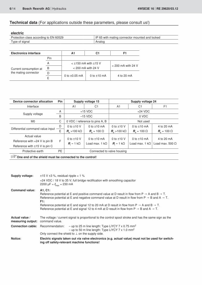
electricProtection class according to EN 60529 IP 65 with mating connector mounted and lockedType of signal Analog
Electronics interface A1 C1 F1Pin
Current consumption at the mating connector
A < ±150 mA with ±15 V< 200 mA with 24 V
< 200 mA with 24 VBD
0 to ±0.05 mA 0 to ±10 mA 4 to 20 mAE
Device connector allocation Pin Supply voltage 15 Supply voltage 24Interface A1 C1 A1 C1 F1
Supply voltageA +15 VDC +24 VDCB –15 VDC 0 VDC
M0 C 0 VDC / reference to pins A, B Not used
Differential command value inputD 0 to ±10 V
Re >100 kΩ0 to ±10 mARe = 100 Ω
0 to ±10 VRe >100 kΩ
0 to ±10 mARe = 100 Ω
4 to 20 mARe = 100 ΩE
Actual valueF
0 to ±10 VRi ≈ 1 kΩ
0 to ±10 mALoad max. 1 kΩ
0 to ±10 VRi ≈ 1 kΩ
0 to ±10 mALoad max. 1 kΩ
4 to 20 mALoad max. 500 Ω
Reference with +24 V is pin BReference with ±15 V is pin C
Protective earth PE Connected to valve housing
One end of the shield must be connected to the control!
Supply voltage: ±15 V ±3 %, residual ripple < 1 %+24 VDC / 18 V to 35 V; full bridge rectification with smoothing capacitor 2200 μF = Imax = 230 mA
Command value: A1, C1: Reference potential at E and positive command value at D result in flow from P → A and B → T. Reference potential at E and negative command value at D result in flow from P → B and A → T. F1: Reference potential at E and signal 12 to 20 mA at D result in flow from P → A and B → T. Reference potential at E and signal 12 to 4 mA at D result in flow from P → B and A → T.
Actual value / measuring output:
The voltage / current signal is proportional to the control spool stroke and has the same sign as the command value.
Connection cable: Recommendation: – up to 25 m line length: Type LiYCY 7 x 0.75 mm2 – up to 50 m line length: Type LiYCY 7 x 1.0 mm2 Only connect the shield to ⊥ on the supply side.
Notice: Electric signals taken out via valve electronics (e.g. actual value) must not be used for switch-ing off safety-relevant machine functions!
Technical data (For applications outside these parameters, please consult us!)

Hydraulics Bosch Rexroth AGRE 29620/03.12 4WSE3E 16 7/14
Block diagram of the integrated electronics (OBE)
Interface Integrated electronics (OBE) Valve
Dither generator
Amplitude1)
Controller Current controller Output stage
Servo-valve
Position transducerOscillator
Demodulator
Zero point main stage 2)
Differential command value input±10 V or ±10 mA or 4 to 20 mA
Actual value ±10 V / ±10 mA (measuring output F has positive poten-tial against ⊥ with flow P → A)
1) 2)
Changes in the zero point and/or the dither amplitude may result in damage to the system and may only be imple-mented by instructed specialists.
Actual value 4 to 20 mA (measuring output F is larger than 12 mA against ⊥ with flow P → A)
Supply voltage
±15 V 24 VA +15 V 18 V to 35 VB –15 V 0 VC ⊥ M0 n.c.

8/14 Bosch Rexroth AG Hydraulics 4WSE3E 16 RE 29620/03.12
Rated flow1 = 100 l/min2 = 150 l/min3 = 200 l/min4 = 300 l/min
Characteristic curves (measured with HLP46, ϑoil = 40 °C ± 5 °C)
Valve pressure differential in bar →
Flow
in l/
min
→Flow/load function (tolerance ±10 %) with 100 % command value signal
Δp = Valve pressure differential (inlet pressure pP minus load pressure pL minus return flow pressure pT)
Tolerance field of the flow/signal function at constant valve pressure differential
Summated edge ΔpV = 70 bar Single edge ΔpV = 35 bar (tolerance ±5 %)
Command value* in % →Command value* in % →
Tolerance field
Typical flow curve
Flow
in %
Flow
in %
* With interface F1, the negative command value axis corresponds to 4 to 12 mA, the positive command value axis to 12 to 20 mA

Hydraulics Bosch Rexroth AGRE 29620/03.12 4WSE3E 16 9/14
Zero flowData valid for overlap "E"
Pilot control valve L1 l/minpP
70 bar≤ • 0.5
Overall valve qV l/minpP
70 bar≤ • 0.015 • qVnom
Characteristic curves (measured with HLP32, ϑoil = 40 °C ± 5 °C)
Pressure signal characteristic curve
Measured at 280 bar operating pressure
Zero flow total with "D" overlap (pilot control valve and main stage)Tolerance ±20 %
Flow
in l/
min
→
Valve pressure differential in bar →
qVnom Rated flow (overall valve) in l/min 105, 150, 200, 260
pP Operating pressure in bar
Δp Valve pressure differential in barqV 100, 150, 200, 300 l/min
1 = 100 l/min2 = 150 l/min3 = 200 l/min4 = 300 l/min
in % →UE
UON
in %
→Δ
p LΔ
p

10/14 Bosch Rexroth AG Hydraulics 4WSE3E 16 RE 29620/03.12
Characteristic curves (measured with HLP32, ϑoil = 40 °C ± 5 °C)
Transition function – measured with 210 bar pressure rating
Frequency response at pP = 210 bar – measured with 210 bar pressure rating
Ampl
itude
ratio
in d
B →
Frequency in Hz →
Cont
rol s
pool
stro
ke in
% →
Time in ms →
Pilot pressure 40 bar 70 bar 140 bar 210 bar
Command value signal ±1 % ±5 % ±25 % ±100 %
Dependence of the –90° frequency on the pilot pressure – measured with 210 bar pressure rating
Inle
t am
plitu
de in
% →
Frequency at –90° in Hz →
Pilot pressure 40 bar 70 bar 140 bar 210 bar
Phas
e an
gle
in °

Hydraulics Bosch Rexroth AGRE 29620/03.12 4WSE3E 16 11/14
Characteristic curves (measured with HLP32, ϑoil = 40 °C ± 5 °C)
Transition function – measured with 315 bar pressure rating
Frequency response at pP = 315 bar – measured with 315 bar pressure rating
Ampl
itude
ratio
in d
B →
Frequency in Hz →
Cont
rol s
pool
stro
ke in
% →
Time in ms →
Pilot pressure 40 bar 70 bar 140 bar 210 bar 315 bar
Command value signal ±1 % ±5 % ±25 % ±100 %
Dependence of the –90° frequency on the pilot pressure – measured with 315 bar pressure rating
Inle
t am
plitu
de in
% →
Frequency at –90° in Hz →
Pilot pressure 40 bar 70 bar 140 bar 210 bar 315 bar
Output signal corresponds to control spool stroke without flow
Phas
e an
gle
in °

12/14 Bosch Rexroth AG Hydraulics 4WSE3E 16 RE 29620/03.12
Unit dimensions: Type 4WSE3E 16 (dimensions in mm)
Required surface quality of the valve mounting face
1 Name plate – overall valve2 Name plate – pilot control valve3 Mating connector according to EN 175201-804,
separate order, see page 134 Space required to remove the mating connector, take
connection cable into account!5 PVC cable not resistant when in contact with HFD-R fluid6 Locating pin (2 units) G1 and G27 Cover plate (for transport only)8 Pilot control valve (2-stage)9 Main stage (3rd stage)
10 Integrated control electronics11 Identical seal rings for ports A, B, P, and T12 Identical seal rings for ports X and Y
The ports X and Y are also pressurized in the case of "internal" pilot oil supply
13 Machined valve mounting face, porting pattern according to ISO 4401-07-07-0-05
14 Exchangeable filter element with seal, material no. R961000194
15 Valve mounting screws16 Hexagon nuts (for transport only)
Hexagon socket head cap screws (included in the delivery) Material numberSize 16 2x ISO 4762 - M6 x 60 - 10.9-flZn-240h-L
Tightening torque MA = 12.5 Nm ±10 %4x ISO 4762 - M10 x 60 - 10.9-flZn-240h-L Tightening torque MA = 58 Nm ±10 %
R913000115
R913000116
Notice: The tightening torque of the hexagon socket head cap screws refers to the maximum operating pressure!

Hydraulics Bosch Rexroth AGRE 29620/03.12 4WSE3E 16 13/14
Flushing plate with porting pattern according to ISO 4401-07-07-0-05 (dimensions in mm)
1 R-ring 10 x 2 x 2 (L, X, Y) included in scope of delivery2 R-ring 22.53 x 2.30 x 2.62 (P, T, A, B) included in scope
of delivery3 2 hexagon socket head cap screws (included in the scope
of delivery) ISO4762-M6x70-10.9flZn-240h-L (friction coefficient 0.09 to 0.14 according to VDA 235-101) MA = 15.5 Nm ±20 % Material no. R913000282
4 4 hexagon socket head cap screws (included in the scope of delivery) ISO4762-M10x70-10.9flZn-240h-L (friction coefficient 0.09 to 0.14 according to VDA 235-101) MA = 75 Nm ±20 % Material no. R913000126
5 2 locating pins 3 x 8 - A2C DIN EN 287416 Name plate
Symbols
with FKM seals, material no. R900904218 Weight: 4.75 kg
To ensure proper functioning of the servo-valves, it is neces-sary to flush the system before commissioning.The following values are guidelines for the flushing time per system: t = Flushing time in hours V = Tank capacity in literst ≥ ― • 5
VqV qV = Pump flow in liters per minute
When topping up more than 10 % of the tank capacity, the flushing procedure must be repeated.The use of a directional valve with port in accordance with ISO 4401-07-07-0-05 is better suited than a flushing plate. With this valve, you can also flush the actuator ports.
with FKM seals, material no. R900959376 (without fig.) Weight: 4.5 kg
Accessories (not included in the scope of delivery)
Mating connectors Material numberMating connector for servo-valve DIN EN 175201-804, see data sheet 08006 R900223890 (metal)
Subplates Data sheetSize 16 45056

Bosch Rexroth AG HydraulicsZum Eisengießer 197816 Lohr am Main, Germany Phone +49 (0) 93 52 / [email protected] www.boschrexroth.de
© This document, as well as the data, specifications and other informa-tion set forth in it, are the exclusive property of Bosch Rexroth AG. It may not be reproduced or given to third parties without its consent.The data specified above only serve to describe the product. No state-ments concerning a certain condition or suitability for a certain applica-tion can be derived from our information. The information given does not release the user from the obligation of own judgment and verification. It must be remembered that our products are subject to a natural process of wear and aging.
14/14 Bosch Rexroth AG Hydraulics 4WSE3E 16 RE 29620/03.12
Notes

Bosch Rexroth AG HydraulicsZum Eisengießer 197816 Lohr am Main, Germany Phone +49 (0) 93 52 / [email protected] www.boschrexroth.de
© This document, as well as the data, specifications and other informa-tion set forth in it, are the exclusive property of Bosch Rexroth AG. It may not be reproduced or given to third parties without its consent.The data specified above only serve to describe the product. No state-ments concerning a certain condition or suitability for a certain applica-tion can be derived from our information. The information given does not release the user from the obligation of own judgment and verification. It must be remembered that our products are subject to a natural process of wear and aging.
Hydraulics Bosch Rexroth AGRE 29620/03.12 4WSE3E 16 15/14

Bosch Rexroth AG HydraulicsZum Eisengießer 197816 Lohr am Main, Germany Phone +49 (0) 93 52 / [email protected] www.boschrexroth.de
© This document, as well as the data, specifications and other informa-tion set forth in it, are the exclusive property of Bosch Rexroth AG. It may not be reproduced or given to third parties without its consent.The data specified above only serve to describe the product. No state-ments concerning a certain condition or suitability for a certain applica-tion can be derived from our information. The information given does not release the user from the obligation of own judgment and verification. It must be remembered that our products are subject to a natural process of wear and aging.
16/14 Bosch Rexroth AG Hydraulics 4WSE3E 16 RE 29620/03.12

1/14
Information on available spare parts: www.boschrexroth.com/spc
Directional servo-valve in 4-way version
Type 4WSE3E 25
Size 25Component series 3XMaximum operating pressure 350 barMaximum flow 1020 l/min
RE 29621/03.12Replaces: 05.09
Table of contents Features
– Valve for position, force, pressure or velocity control– 3-stage servo-valve with electrical position control of the
control spool of the 3rd stage, position sensing of the control spool by means of an inductive position transducer
– High dynamics 2-stage pilot control valve of size 6– 1st stage as nozzle flapper plate amplifier– Filter for 1st stage externally accessible and replaceable– Subplate mounting:
Porting pattern according to ISO 4401– Can also be used as 3-way version– Valve and integrated control electronics are adjusted and
tested in the factory– Optimized valve control loop– High response sensitivity, very low hysteresis and zero
point drift– Internal or external pilot oil supply and return– Gap seals at pressure chambers of the control sleeve,
no wear of O-ring
Contents PageFeatures 1Ordering code 2Symbol 2Function, section 3Technical data 4 to 6Block diagram of the integrated electronics (OBE) 7Characteristic curves 8 to 11Unit dimensions 12Flushing plate with porting pattern according to ISO 4401 13Accessories 14
InhaltTable of contents 1Features 1Ordering code 2Symbol 2Function, section 3Technical data (For applications outside these parameters, please consult us!) 4Technical data (For applications outside these parameters, please consult us!) 5Technical data (For applications outside these parameters, please consult us!) 6Block diagram of the integrated electronics (OBE) 7Characteristic curves (measured with HLP46oil = 40 °C ± 5 °C) 8Characteristic curves (measured with HLP32,l = 40 °C ± 5 °C) 9Characteristic curves (measured with HLP32oil = 40 °C ± 5 °C) 10Characteristic curves (measured with HLP32il = 40 °C ± 5 °C) 11Unit dimensions: Type 4WSE3E 25 (dimensions in mm) 12Flushing plate with porting pattern according to ISO 4401-08-08-0-05 (dimensions in mm) 13Accessories (not included in the scope of delivery) 13Notes 14

2/14 Bosch Rexroth AG Hydraulics 4WSE3E 25 RE 29621/03.12
Ordering code
3-stage servo-valve SizeSize 25 = 25Control spool symbol 1)
Control spool position in de-energized stateNot defined = no code 100 % P → A / B → T = PRated flow 2)
210 l/min = 200 300 l/min = 300 380 l/min = 400 450 l/min = 500Control spool overlap 3)
0 to 0.5 % positive = D 0 to 0.5 % negative = EComponent series 30 to 39 = 3X (30 to 39: Unchanged installation and connection dimensions)Seal material 4)
FKM seals = V NBR seals = M
Further details in the plain text
Electronics interface command/actual value
A1 = 0 to 10 V C1 = 0 to 10 mA F1* = 4 to 20 mA
Electrical connectionK31 = 6+PE
Without mating connectorSupply voltage
15 = ±15 V 24 = +24 V
See page 6Pressure rating 6)
7 = 210 bar 9 = 315 bar
Pilot flow 5)
XY = Pilot oil supply external, return externalXT = Pilot oil supply external, return internalPY = Pilot oil supply internal, return externalPT = Pilot oil supply internal, return internal * Only with +24 V supply voltage
4WSE3E 25 3X K31 *
1) Control spool symbols with control spool symbol V P → A; qV max B → T; qV max P → B; qV max A → T; qV max with control spool symbol V1 P → A; qV max B → T; qV / 2 P → B; qV / 2 A → T; qV max
2) Rated flow The rated flow refers to a 100 % command value signal at 70 bar valve pressure differential (35 bar per control edge). The valve pressure differential must be regarded as reference. Other values result in the flow being changed. A possible rated flow tolerance of ±10 % and a saturation influence must be taken into account (see flow/signal func-tion page 8).
3) Control spool overlap The control spool overlap in % is referred to the nominal stroke of the control spool. (Other control spool overlaps upon request.)
4) Seal material See notice on page 5
5) Pilot oil Care should be taken that the pilot pressure is as constant as possible. An external pilot control via port X is thus often advantageous.
6) Inlet pressure range Care should be taken that the inlet pressure is as constant as possible. Minimum pilot pressure ≥ 10 bar. Up to a pilot pressure of 210 bar, pressure rating 7 is to be selected. From a pilot pressure greater than 210 bar, pres-sure rating 9 is to be selected. With regard to the dynamics, the frequency response depen-dency must be observed within the admissible pressure range. At an inlet pressure > 40 bar, the pilot pressure must not be less than 60 % of the inlet pressure as otherwise the cur-rent forces at the control spool of the 3rd stage will impair the controllability. At an inlet pressure ≤ 40 bar, working with a pilot pressure above port X (external supply) is in any case advantageous.
Symbol
= V= V1

Hydraulics Bosch Rexroth AGRE 29621/03.12 4WSE3E 25 3/14
Function, sectionValves of type 4WSE3E 25 are electrically operated, 3-stage directional servo-valves. They are mainly used for position, force or pressure and velocity controls.These valves consist of a 2-stage pilot control valve of type 4WS2EM 6 (1), a main stage with a main control spool in a sleeve (2), an inductive position transducer (3), and inte-grated control electronics (4).The pilot control valve (1) consists of an electro-mechanical transformer (torque motor), a hydraulic amplifier (nozzle flap-per plate principle) and a pilot control spool in a sleeve, which is connected to the torque motor via a mechanical feedback.Electric currents in the coils of the torque motor generate a force by means of a permanent magnet which acts on the armature, and in connection with a torque tube results in a torque. This causes the flapper plate which is connected to the torque tube via a pin to move from the central position be-tween the two control nozzles, and a pressure differential is created across the front sides of the pilot control spool. The pressure differential results in the control spool changing its position, which results in the pressure port being connected to one actuator port and, at the same time, the other actuator port being connected to the return flow port.The pilot control spool is connected to the flapper plate or the torque motor by means of a bending spring (mechani-cal feedback).
The position of the control spool is changed until the flapper plate position and hence the pressure differential across the nozzle flapper plate system becomes zero due to the feed-back torque, which acts via the bending spring against the electro-magnetic torque of the torque motor.In doing so, the stroke of the pilot control spool and hence the flow of the pilot control valve is controlled proportionally to the electrical input signal (see data sheet 29564).In the main stage, the main control spool (2) is operated by the pilot control valve and its position is sensed by an induc-tive position transducer (3). The position transducer signal is compared to the command value by integrated control elec-tronics (4). Any possible control deviation is amplified electri-cally and fed to the pilot control valve as control signal. The pilot control valve starts to move and the main control spool is re-positioned. The stroke of the main control spool and consequently the flow of the servo-valve are controlled in proportion to the com-mand value. It must be noted that the flow depends on the valve pressure differential. The valve zero point can be adjusted by means of an exter-nally accessible potentiometer.The valves are factory-set with a dither default setting with the constant frequency of 400 Hz.
Notice!Changes in the zero point and/or the dither amplitude may result in damage to the system and may only be implemented by instructed specialists.
The pilot control valve may only be maintained by Bosch Rexroth employees. An exception to this is the re-placement of the filter element – see data sheet 29564.
The sensitivity of the main stage must not be changed!
Zero point main stage, adjustment range maximally ±5 %
Plug screw Pg7
Dither amplitude

4/14 Bosch Rexroth AG Hydraulics 4WSE3E 25 RE 29621/03.12
Technical data (For applications outside these parameters, please consult us!)generalWeight kg 16Installation position Any, if it is ensured that the pilot control is supplied
with sufficient pressure (> 10 bar) during start-up of the system. In case of insufficient pressure supply, the control spool of the servo-valve can take any position. This may result in channel P being con-nected to the actuator and the build-up of pressure being delayed. This may be prevented by providing an external pressure supply at port X.
Storage temperature range °C –20 to +80Ambient temperature range °C –20 to +60
hydraulic (measured with HLP 32, ϑOil = 40 °C ± 5 °C)Maximum operating pressure
Pilot control stage, pilot oil supply X bar 10 to 210 and/or 10 to 315 (see page 2, pressure rating)Main valve, port P, A, B
Pilot oil supply internalbar 315
Main valve, port P, A, B
Pilot oil supply externalbar 350
Maximum return flow pressure
Pilot control stage, port Y bar Pressure peaks < 100 admissible, static < 10
Main valve, port T
Pilot oil return internal bar Pressure peaks < 100 admissible, static < 10Pilot oil return external bar 250
Leakage flow See page 9 (characteristic curves)Rated flow qVnom ±10 % with Δp = 70 bar l/min 210, 300, 380, 450Hydraulic fluid See table page 5Hydraulic fluid temperature range °C –20 to +80; preferably +40 to +50Viscosity range mm2/s 15 to 380; preferably 30 to 45Maximum admissible degree of contamination of the hy-draulic fluid cleanliness class according to ISO 4406 (c)
Pilot control valve
Class 18/16/13 1)
Main stage Class 20/18/15 1)
Hysteresis % ≤ 0.10Range of inversion % ≤ 0.05Response sensitivity % ≤ 0.05Pressure gain ≥ 90 % of pP
2) with 1 % change in the control spool stroke (from hydraulic zero point)
Zero shift upon change of:
Hydraulic fluid temperature % / 10 K ≤ 0.3Ambient temperature % / 10 K ≤ 0.3Operating pressure % / 100 bar ≤ 0.3Return flow pressure 0 to 10 % of pP % / 100 bar ≤ 0.3
1) The cleanliness classes specified for the components must be adhered to in hydraulic systems. Effective filtration prevents faults and at the same time increases the service life of the components. For the selection of the filters see www.boschrexroth.com/filter
2) pP = Inlet pressure/operating pressure
Notice! For information on the environment simulation testing for the areas EMC (electromagnetic compatibility), climate and me-chanical load, see data sheet 29620-U.

Hydraulics Bosch Rexroth AGRE 29621/03.12 4WSE3E 25 5/14
Technical data (For applications outside these parameters, please consult us!)
Hydraulic fluid Classification Suitable sealing materials StandardsMineral oils and related hydrocarbons HL, HLP NBR, FKM DIN 51524Flame-resistant
– containing waterHFCFuchs Hydrotherm 46M Petrofer Ultra Safe 620
NBR ISO 12922
Important information on hydraulic fluids!– For more information and data on the use of other hydrau-
lic fluids refer to data sheet 90220 or contact us!– There may be limitations regarding the technical valve
data (temperature, pressure range, service life, mainte-nance intervals, etc.)!
– Flame-resistant – containing water: Maximum pressure differential per control edge 210 bar,
otherwise, increased cavitation erosion! Tank pre-loading < 1 bar or > 20 % of the pressure dif-ferential of the tank edge. The pressure peaks should not exceed the maximum operating pressures!
Maximum fluid temperature 60 °C

6/14 Bosch Rexroth AG Hydraulics 4WSE3E 25 RE 29621/03.12
electricProtection class according to EN 60529 IP 65 with mating connector mounted and lockedType of signal Analog
Electronics interface A1 C1 F1Pin
Current consumption at the mating connector
A < ±150 mA with ±15 V< 200 mA with 24 V
< 200 mA with 24 VBD
0 to ±0.05 mA 0 to ±10 mA 4 to 20 mAE
Device connector allocation Pin Supply voltage 15 Supply voltage 24Interface A1 C1 A1 C1 F1
Supply voltageA +15 VDC +24 VDCB –15 VDC 0 VDC
M0 C 0 VDC / reference to pins A, B Not used
Differential command value inputD 0 to ±10 V
Re >100 kΩ0 to ±10 mARe = 100 Ω
0 to ±10 VRe >100 kΩ
0 to ±10 mARe = 100 Ω
4 to 20 mARe = 100 ΩE
Actual valueF
0 to ±10 VRi ≈ 1 kΩ
0 to ±10 mALoad max. 1 kΩ
0 to ±10 VRi ≈ 1 kΩ
0 to ±10 mALoad max. 1 kΩ
4 to 20 mALoad max. 500 Ω
Reference with +24 V is pin BReference with ±15 V is pin C
Protective earth PE Connected to valve housing
One end of the shield must be connected to the control!
Supply voltage: ±15 V ±3 %, residual ripple < 1 %+24 VDC / 18 V to 35 V; full bridge rectification with smoothing capacitor 2200 μF = Imax = 230 mA
Command value: A1, C1: Reference potential at E and positive command value at D result in flow from P → A and B → T. Reference potential at E and negative command value at D result in flow from P → B and A → T. F1: Reference potential at E and signal 12 to 20 mA at D result in flow from P → A and B → T. Reference potential at E and signal 12 to 4 mA at D result in flow from P → B and A → T.
Actual value / mea-suring output:
The voltage / current signal is proportional to the control spool stroke and has the same sign as the command value.
Connection cable: Recommendation: – up to 25 m line length: Type LiYCY 7 x 0.75 mm2 – up to 50 m line length: Type LiYCY 7 x 1.0 mm2 Only connect the shield to ⊥ on the supply side.
Notice: Electric signals taken out via valve electronics (e.g. actual value) must not be used for switch-ing off safety-relevant machine functions!
Technical data (For applications outside these parameters, please consult us!)

Block diagram of the integrated electronics (OBE)
Interface Integrated electronics (OBE) Valve
Dither generator
Amplitude1)
Controller Current controller Output stage
Servo-valve
Position transducerOscillator
Demodulator
Zero point main stage 2)
Differential command value input±10 V or ±10 mA or 4 to 20 mA
Actual value ±10 V /±10 mA (measuring output F has positive poten-tial against ⊥ with flow P → A)
1) 2)
Changes in the zero point and/or the dither amplitude may result in damage to the system and may only be imple-mented by instructed specialists.
Actual value 4 to 20 mA (measuring output F is larger than 12 mA against ⊥ with flow P → A)
Supply voltage
±15 V 24 VA +15 V 18 V to 35 VB –15 V 0 VC ⊥ M0 n.c.
Hydraulics Bosch Rexroth AGRE 29621/03.12 4WSE3E 25 7/14

8/14 Bosch Rexroth AG Hydraulics 4WSE3E 25 RE 29621/03.12
Characteristic curves (measured with HLP46, ϑoil = 40 °C ± 5 °C)
Valve pressure differential in bar →
Flow
in l/
min
→Flow/load function (tolerance ±10 %) with 100 % command value signal
Δp = Valve pressure differential (inlet pressure pP minus load pressure pL minus return flow pressure pT)
Tolerance field of the flow/signal function at constant valve pressure differential
Flow
in %
Actual value in % →
Flow
in %
Actual value in % →
Tolerance field
Typical flow curve
Summated edge ΔpV = 70 bar Single edge ΔpV = 35 bar (tolerance ±5 %)
* With interface F1, the negative command value axis corresponds to 4 to 12 mA, the positive command value axis to 12 to 20 mA
Rated flow1 = 200 l/min2 = 300 l/min3 = 400 l/min4 = 500 l/min

Hydraulics Bosch Rexroth AGRE 29621/03.12 4WSE3E 25 9/14
Characteristic curves (measured with HLP32, ϑoil = 40 °C ± 5 °C)
Pressure signal characteristic curve
Zero flow total with "D" overlap (pilot control valve and main stage)Tolerance ±20 %
Flow
in l/
min
→
Valve pressure differential in bar →
qVnom Rated flow (overall valve) in l/min 210, 300, 380, 450
pP Operating pressure in bar
Δp Valve pressure differential in barqV 200, 300, 400, 500 l/min
Measured at 280 bar operating pressure
1 = 200 l/min2 = 300 l/min3 = 400 l/min4 = 500 l/min
in % →UE
UON
in %
→Δp L
Δp
Zero flowData valid for overlap "E"
Pilot control valve L1 l/minpP
70 bar≤ • 0.55
Overall valve qV l/minpp
70 bar≤ • 0.015 • qVnom

10/14 Bosch Rexroth AG Hydraulics 4WSE3E 25 RE 29621/03.12
Characteristic curves (measured with HLP32, ϑoil = 40 °C ± 5 °C)
Transition function – measured with 210 bar pressure rating
Frequency response at pP = 210 bar – measured with 210 bar pressure rating
Ampl
itude
ratio
in d
B →
Frequency in Hz →
Cont
rol s
pool
stro
ke in
% →
Time in ms →
Command value signal ±1 % ±5 % ±25 % ±100 %
Dependence of the –90° frequency on the pilot pressure – measured with 210 bar pressure rating
Inle
t am
plitu
de in
% →
Frequency at –90° in Hz →
Phas
e an
gle
in °
Pilot pressure 40 bar 70 bar 100 bar 140 bar 210 bar
Pilot pressure
40 bar
70 bar
100 bar
140 bar
210 bar

Hydraulics Bosch Rexroth AGRE 29621/03.12 4WSE3E 25 11/14
Characteristic curves (measured with HLP32, ϑoil = 40 °C ± 5 °C)
Transition function – measured with 315 bar pressure rating
Frequency response at pP = 315 bar – measured with 315 bar pressure rating
Ampl
itude
ratio
in d
B →
Frequency in Hz →
Cont
rol s
pool
stro
ke in
% →
Time in ms →
Pilot pressure 40 bar 70 bar 100 bar 140 bar 210 bar 315 bar
Command value signal ±1 % ±5 % ±25 % ±100 %
Dependence of the –90° frequency on the pilot pressure – measured with 315 bar pressure rating
Inle
t am
plitu
de in
% →
Frequency at –90° in Hz →
Pilot pressure
40 bar
70 bar
100 bar
140 bar
210 bar
315 bar
Phas
e an
gle
in °

12/14 Bosch Rexroth AG Hydraulics 4WSE3E 25 RE 29621/03.12
Unit dimensions: Type 4WSE3E 25 (dimensions in mm)
Required surface quality of the valve mounting face
1 Name plate – overall valve2 Name plate – pilot control valve3 Mating connector according to EN 175201-804,
separate order, see page 134 Space required to remove the mating connector,
take connection cable into account!5 PVC cable not resistant when in contact with HFD-R fluid6 Locating pin (2 units) G1 and G27 Cover plate (for transport only)8 Pilot control valve (2-stage)9 Main stage (3rd stage)
10 Integrated control electronics11 Identical seal rings for ports A, B, P, and T12 Identical seal rings for ports X and Y
The ports X and Y are also pressurized in the case of "internal" pilot oil supply
13 Machined valve mounting face, porting pattern according to ISO 4401-08-08-0-05
14 Exchangeable filter element with seal, material no. R961000194
15 Valve mounting screws16 Hexagon nuts (for transport only)
Hexagon socket head cap screws (included in the scope of delivery) Material numberSize 25 6x ISO 4762 - M12 x 60 - 10.9-flZn-240h-L
Tightening torque MA = 100 Nm ±10 %R913000121
Notice: The tightening torque of the hexagon socket head cap screws refers to the maximum operating pressure!

Accessories (not included in the scope of delivery)
Mating connectors Material numberMating connector for servo-valve DIN EN 175201-804, see data sheet 08006 R900223890 (metal)
Subplates Data sheetSize 25 45058
Hydraulics Bosch Rexroth AGRE 29621/03.12 4WSE3E 25 13/14
Flushing plate with porting pattern according to ISO 4401-08-08-0-05 (dimensions in mm)
1 R-ring 19x3x3 (X, Y) included in scope of delivery2 R-ring 27.8x2.6x3 (P, T, A, B) included in scope
of delivery3 6 hexagon socket head cap screws
(included in scope of delivery)ISO4762-M12x80-10.9 (friction coefficient 0.09 to 0.14 according to VDA 235-101) MA = 100 Nm Material no. R913000413
4 2 locating pins ISO8741 - 6X12-ST5 Name plate
Symbolswith FKM seals, Material no. R900959384 Weight: 8.4 kg
To ensure proper functioning of the servo-valves, it is necessary to flush the system before commissioning.The following values are guidelines for the flushing time per system: t = Flushing time in hours V = Tank capacity in liters qV = Pump flow in liters per minuteWhen topping up more than 10 % of the tank capac-ity, the flushing procedure must be repeated.The use of a directional valve with port in accor-dance with ISO 4401-08-08-0-05 is better suited than a flushing plate. With this valve, you can also flush the actuator ports.
with FKM seals, Material no. R900959377 (without fig.) Weight: 8.4 kg
t ≥ ― • 5VqV

Bosch Rexroth AG HydraulicsZum Eisengießer 197816 Lohr am Main, Germany Phone +49 (0) 93 52 / [email protected] www.boschrexroth.de
© This document, as well as the data, specifications and other informa-tion set forth in it, are the exclusive property of Bosch Rexroth AG. It may not be reproduced or given to third parties without its consent.The data specified above only serve to describe the product. No state-ments concerning a certain condition or suitability for a certain applica-tion can be derived from our information. The information given does not release the user from the obligation of own judgment and verification. It must be remembered that our products are subject to a natural process of wear and aging.
14/14 Bosch Rexroth AG Hydraulics 4WSE3E 25 RE 29621/03.12
Notes

Bosch Rexroth AG HydraulicsZum Eisengießer 197816 Lohr am Main, Germany Phone +49 (0) 93 52 / [email protected] www.boschrexroth.de
© This document, as well as the data, specifications and other informa-tion set forth in it, are the exclusive property of Bosch Rexroth AG. It may not be reproduced or given to third parties without its consent.The data specified above only serve to describe the product. No state-ments concerning a certain condition or suitability for a certain applica-tion can be derived from our information. The information given does not release the user from the obligation of own judgment and verification. It must be remembered that our products are subject to a natural process of wear and aging.
Hydraulics Bosch Rexroth AGRE 29621/03.12 4WSE3E 25 15/14

Bosch Rexroth AG HydraulicsZum Eisengießer 197816 Lohr am Main, Germany Phone +49 (0) 93 52 / [email protected] www.boschrexroth.de
© This document, as well as the data, specifications and other informa-tion set forth in it, are the exclusive property of Bosch Rexroth AG. It may not be reproduced or given to third parties without its consent.The data specified above only serve to describe the product. No state-ments concerning a certain condition or suitability for a certain applica-tion can be derived from our information. The information given does not release the user from the obligation of own judgment and verification. It must be remembered that our products are subject to a natural process of wear and aging.
16/14 Bosch Rexroth AG Hydraulics 4WSE3E 25 RE 29621/03.12

1/14
Information on available spare parts: www.boschrexroth.com/spc
Directional servo-valve in 4-way version
Type 4WSE3E 32
Size 32Component series 5XMaximum operating pressure 315 barMaximum flow 1800 l/min
RE 29622/03.12Replaces: 05.09
Table of contents Features
– Valve for position, force, pressure or velocity control– 3-stage servo-valve with electrical position control of the
control spool of the 3rd stage, position sensing of the control spool by means of an inductive position transducer
– High dynamics 2-stage pilot control valve of size 6– 1st stage as nozzle flapper plate amplifier– Filter for 1st stage externally accessible and replaceable– Subplate mounting:
Porting pattern according to ISO 4401– Can also be used as 3-way version– Valve and integrated control electronics are adjusted and
tested in the factory– Optimized valve control loop– High response sensitivity, very low hysteresis and zero
point drift– Internal or external pilot oil supply and return– Gap seals at pressure chambers of the control sleeve, no
O-ring wear
Contents PageFeatures 1Ordering code 2Symbol 2Function, section 3Technical data 4 to 6Block diagram of the integrated electronics (OBE) 7Characteristic curves 8 to 11Unit dimensions 12Flushing plate with porting pattern according to ISO 4401 13Accessories 13
H7357
InhaltTable of contents 1Features 1Ordering code 2Symbol 2Function, section 3Technical data (For applications outside these parameters, please consult us!) 4Technical data (For applications outside these parameters, please consult us!) 5Technical data (For applications outside these parameters, please consult us!) 6Block diagram of the integrated electronics (OBE) 7Characteristic curves (measured with HLP46,oil = 40 °C ± 5 °C) 8Characteristic curves (measured with HLP32oil = 40 °C ± 5 °C) 9Characteristic curves (measured with HLP32oil = 40 °C ± 5 °C) 10Characteristic curves (measured with HLP32,oil = 40 °C ± 5 °C) 11Unit dimensions: Type 4WSE3E 32 (dimensions in mm) 12Flushing plate with porting pattern according to ISO 4401-10-09-0-05 (dimensions in mm) 13Accessories (not included in the scope of delivery) 13Notes 14

2/14 Bosch Rexroth AG Hydraulics 4WSE3E 32 RE 29622/03.12
Ordering code
3-stage servo-valve SizeSize 32 = 32Control spool symbol 1)
Control spool position in de-energized stateNot defined = no code 100 % P → A / B → T = PRated flow 2)
500 l/min = 500 670 l/min = 700 890 l/min = 1000Control spool overlap 3)
0 to 0.5 % positive = D 0 to 0.5 % negative = EComponent series 50 to 59 = 5X (50 to 59: Unchanged installation and connection dimensions)Seal material 4)
FKM seals = V NBR seals = M
Further details in the plain text
Electronics interface command/actual value
A1 = 0 to 10 V C1 = 0 to 10 mA F1* = 4 to 20 mA
Electrical connectionK31 = 6+PE
Without mating connectorSupply voltage
15 = ±15 V 24 = +24 V
See page 6Pressure rating 6)
7 = 210 bar 9 = 315 bar
Pilot flow 5)
XY = Pilot oil supply external, return externalXT = Pilot oil supply external, return internalPY = Pilot oil supply internal, return externalPT = Pilot oil supply internal, return internal * Only with +24 V supply voltage
4WSE3E 32 5X K31 *
1) Control spool symbols with control spool symbol V P → A; qV max B → T; qV max P → B; qV max A → T; qV max with control spool symbol V1 P → A; qV max B → T; qV / 2 P → B; qV / 2 A → T; qV max
2) Rated flow The rated flow refers to a 100 % command value signal at 70 bar valve pressure differential (35 bar per control edge). The valve pressure differential must be regarded as reference. Other values result in the flow being changed. A possible rated flow tolerance of ±10 % and saturation influence must be taken into account (see flow/signal func-tion page 8).
3) Control spool overlap The control spool overlap in % is referred to the nominal stroke of the control spool. (Other control spool overlaps upon request.)
Symbol
= V= V1
4) Seal material See notices on page 5
5) Pilot oil Care should be taken that the pilot pressure is as constant as possible. An external pilot control via port X is thus often advantageous.
6) Inlet pressure range Care should be taken that the inlet pressure is as constant as possible. Minimum control pressure ≥ 10 bar. Up to a pilot pressure of 210 bar, pressure rating 7 is to be selected. From a pilot pressure greater than 210 bar, pres-sure rating 9 is to be selected. With regard to the dynamics, the frequency response depen-dency must be observed within the admissible pressure range. At an inlet pressure > 40 bar, the pilot pressure must not be less than 60 % of the inlet pressure as otherwise the cur-rent forces at the control spool of the 3rd stage will impair the controllability. At an inlet pressure ≤ 40 bar, working with a pilot pressure above port X (external supply) is in any case advantageous.

Hydraulics Bosch Rexroth AGRE 29622/03.12 4WSE3E 32 3/14
Function, section
The pilot control valve may only be maintained by Bosch Rexroth employees. An exception to this is the re-placement of the filter element – see data sheet 29564.
Valves of type 4WSE3E 32 are electrically operated, 3-stage directional servo-valves. They are mainly used for position, force or pressure and velocity controls.These valves consist of a 2-stage pilot control valve of type 4WS2EM 6 (1), a main stage with a main control spool in a sleeve (2), an inductive position transducer (3), and inte-grated control electronics (4).The pilot control valve (1) consists of an electro-mechanical converter (torque motor), a hydraulic amplifier (nozzle flapper plate principle) and a pilot control spool in a sleeve, which is connected to the torque motor via a mechanical feedback.Electric currents in the coils of the torque motor generate a force by means of a permanent magnet which acts on the armature, and in connection with a torque tube results in a torque. This causes the flapper plate which is connected to the torque tube via a pin to move from the central position be-tween the two control nozzles, and a pressure differential is created across the front sides of the pilot control spool. The pressure differential results in the control spool changing its position, which results in the pressure port being connected to one actuator port and, at the same time, the other actuator port being connected to the return flow port.The pilot control spool is connected to the flapper plate or the torque motor by means of a bending spring (mechani-cal feedback).
The position of the control spool is changed until the flapper plate position and hence the pressure differential across the nozzle flapper plate system becomes zero due to the feed-back torque, which acts via the bending spring against the electro-magnetic torque of the torque motor.In doing so, the stroke of the pilot control spool and hence the flow of the pilot control valve is controlled proportionally to the electrical input signal (see data sheet 29564).In the main stage, the main control spool (2) is operated by the pilot control valve and its position is sensed by an induc-tive position transducer (3). The position transducer signal is compared to the command value by integrated control elec-tronics (4). Any possible control deviation is amplified electri-cally and fed to the pilot control valve as control signal. The pilot control valve starts to move and the main control spool is re-positioned. The stroke of the main control spool and consequently the flow of the servo-valve are controlled in proportion to the com-mand value. It must be noted that the flow depends on the valve pressure differential. The valve zero point can be adjusted by means of an exter-nally accessible potentiometer.The valves are factory-set with a dither default setting with the constant frequency of 400 Hz.
Notice!Changes in the zero point and/or the dither amplitude may result in damage to the system and may only be implemented by instructed specialists.
Plug screw Pg7
Zero point main stage, adjustment range maximally ±5 %
The sensitivity of the main stage must not be changed!
Dither amplitude

4/14 Bosch Rexroth AG Hydraulics 4WSE3E 32 RE 29622/03.12
Technical data (For applications outside these parameters, please consult us!)generalWeight kg 35Installation position Any, if it is ensured that the pilot control is supplied with
sufficient pressure (> 10 bar) during start-up of the sys-tem. In case of insufficient pressure supply, the control spool of the servo-valve can take any position. This may result in channel P being connected to the actuator and the build-up of pressure being delayed. This may be prevented by providing an external pressure supply at port X.
Storage temperature range °C –20 to +80Ambient temperature range °C –20 to +60
hydraulic (measured with HLP 32, ϑOil = 40 °C ± 5 °C)Maximum operating pressure
Pilot control stage, pilot oil supply X bar 10 to 210 or 10 to 315 (see page 2, pressure rating)Main valve, port P, A, B
Pilot oil supply internalbar 315
Main valve, port P, A, B
Pilot oil supply externalbar 315
Maximum return flow pressure
Pilot control stage, port Y bar Pressure peaks < 100 admissible, static < 10
Main valve, port T
Pilot oil return internal bar Pressure peaks < 100 admissible, static < 10 Pilot oil return external bar 250
Zero flow See page 9 (characteristic curves)Rated flow qVnom ±10 % at Δp = 70 bar l/min 500, 670, 890Hydraulic fluid See table page 5Hydraulic fluid temperature range °C –20 to +80; preferably +40 to +50Viscosity range mm2/s 15 to 380; preferably 30 to 45Maximum admissible degree of contamination of the hy-draulic fluid cleanliness class according to ISO 4406 (c)
Pilot con-trol valve
Class 18/16/13 1)
Main stage Class 20/18/15 1)
Hysteresis % ≤ 0.10Range of inversion % ≤ 0.05Response sensitivity % ≤ 0.05Pressure gain ≥ 90 % of pP
2) with 1 % change in control spool stroke (from hydraulic zero point)
Zero shift upon change of:
Hydraulic fluid temperature % / 10 K ≤ 0.3Ambient temperature % / 10 K ≤ 0.3Operating pressure % / 100 bar ≤ 0.3Return flow pressure 0 to 10 % of pP % / 100 bar ≤ 0.3
1) The cleanliness classes specified for the components must be adhered to in hydraulic systems. Effective filtration prevents faults and at the same time increases the service life of the components. For the selection of the filters see www.boschrexroth.com/filter
2) pP = Inlet pressure/operating pressure
Notice! For information on the environment simulation testing for the areas EMC (electromagnetic compatibility), climate and me-chanical load, see data sheet 29620-U.

Hydraulics Bosch Rexroth AGRE 29622/03.12 4WSE3E 32 5/14
Technical data (For applications outside these parameters, please consult us!)
Hydraulic fluid Classification Suitable sealing materials
Standards
Mineral oils and related hydrocarbons HL, HLP NBR, FKM DIN 51524Flame-resistant
– containing waterHFCFuchs Hydrotherm 46M Petrofer Ultra Safe 620
NBR ISO 12922
Important information on hydraulic fluids!– For more information and data on the use of other hydrau-
lic fluids refer to data sheet 90220 or contact us!– There may be limitations regarding the technical valve
data (temperature, pressure range, service life, mainte-nance intervals, etc.)!
– Flame-resistant – containing water: Maximum pressure differential per control edge 210 bar,
otherwise, increased cavitation erosion! Tank pre-loading < 1 bar or > 20 % of the pressure dif-ferential of the tank edge. The pressure peaks should not exceed the maximum operating pressures!
Maximum fluid temperature 60 °C

6/14 Bosch Rexroth AG Hydraulics 4WSE3E 32 RE 29622/03.12
electricProtection class according to EN 60529 IP 65 with mating connector mounted and lockedType of signal Analog
Electronics interface A1 C1 F1Pin
Current consump-tion at the mat-ing connector
A < ±150 mA at ±15 V< 200 mA at 24 V
< 200 mA at 24 VBD
0 to ±0.05 mA 0 to ±10 mA 4 to 20 mAE
Device connector allocation Pin Supply voltage 15 Supply voltage 24Interface A1 C1 A1 C1 F1
Supply voltageA +15 VDC +24 VDCB –15 VDC 0 VDC
M0 C 0 VDC / reference to pins A, B Not used
Differential command value inputD 0 to ±10 V
Re >100 kΩ0 to ±10 mARe = 100 Ω
0 to ±10 VRe >100 kΩ
0 to ±10 mARe = 100 Ω
4 to 20 mARe = 100 ΩE
Actual valueF
0 to ±10 VRi ≈ 1 kΩ
0 to ±10 mALoad max. 1 kΩ
0 to ±10 VRi ≈ 1 kΩ
0 to ±10 mALoad max. 1 kΩ
4 to 20 mALoad max. 500 Ω
The reference with +24 V is pin BThe reference with ±15 V is pin C
Protective earth PE Connected to valve housing
One end of the shield must be connected to the control!
Supply voltage: ±15 V ±3 %, residual ripple < 1 %+24 VDC / 18 V to 35 V; full bridge rectification with smoothing capacitor 2200 μF = Imax = 230 mA
Command value: A1, C1: Reference potential at E and positive command value at D result in flow from P → A and B → T. Reference potential at E and negative command value at D result in flow from P → B and A → T. F1: Reference potential at E and signal 12 to 20 mA at D result in flow from P → A and B → T. Reference potential at E and signal 12 to 4 mA at D result in flow from P → B and A → T.
Actual value / measu-ring output:
The voltage / current signal is proportional to the control spool stroke and has the same sign as the command value.
Connection cable: Recommendation: – up to 25 m line length: Type LiYCY 7 x 0.75 mm2 – up to 50 m line length: Type LiYCY 7 x 1.0 mm2 Only connect the shield to ⊥ on the supply side.
Notice: Electric signals taken out via valve electronics (e.g. actual value) must not be used for swit-ching off safety-relevant machine functions!
Technical data (For applications outside these parameters, please consult us!)

Hydraulics Bosch Rexroth AGRE 29622/03.12 4WSE3E 32 7/14
Block diagram of the integrated electronics (OBE)
Interface Integrated electronics (OBE) Valve
Dither generator
Amplitude1)
Controller Current controller Output stage
Servo-valve
Position transducerOscillator
Demodulator
Zero point main stage 2)
Differential command value input±10 V or ±10 mA or 4 to 20 mA
Actual value ±10 V / ±10 mA (measuring output F has positive poten-tial against ⊥ with flow P → A)
1) 2)
Changes in the zero point and/or the dither amplitude may result in damage to the system and may only be imple-mented by instructed specialists.
Actual value 4 to 20 mA (measuring output F is greater 12 mA against ⊥ with flow P → A)
Supply voltage
±15 V 24 VA +15 V 18 V to 35 VB –15 V 0 VC ⊥ M0 n.c.

8/14 Bosch Rexroth AG Hydraulics 4WSE3E 32 RE 29622/03.12
1 = 500 l/min2 = 700 l/min3 = 1000 l/min
Characteristic curves (measured with HLP46, ϑoil = 40 °C ± 5 °C)
Valve pressure differential in bar →
Flow
in l/
min
→Flow/load function (tolerance ±10 %) with 100 % command value signal
Δp = Valve pressure differential (inlet pressure pP minus load pressure pL minus return flow pressure pT)
Tolerance field of the flow/signal function with constant valve pressure differential
Command value in % →Command value in % →
Tolerance field
Typical flow curve
Flow
in %
Flow
in %
Summated edge ΔpV = 70 bar Single edge ΔpV = 35 bar (tolerance ±5 %)
* With interface F1, the negative command value axis corresponds to 4 to 12 mA, the positive command value axis to 12 to 20 mA

in % →UE
UON
in %
→Δp L
Δp
Hydraulics Bosch Rexroth AGRE 29622/03.12 4WSE3E 32 9/14
Characteristic curves (measured with HLP32, ϑoil = 40 °C ± 5 °C)
Pressure signal characteristic curve
Leakage flow total with "D" overlap (pilot control valve and main stage)Tolerance ±20 %
Flow
in l/
min
→
Valve pressure differential in bar →
qVnom Rated flow (overall valve) in l/min 500, 670, 890pP Operating pressure in bar
Δp Valve pressure differential in barqV 500, 700, 1000 l/min
1 = 500 l/min2 = 700 l/min3 = 1000 l/min
Measured at 280 bar operating pressure
Zero flowData valid for overlap "E"
Pilot control valve L1 l/minpP
70 bar≤ • 0.8
Overall valve qV l/minpP
70 bar≤ • 0.015 • qVnom
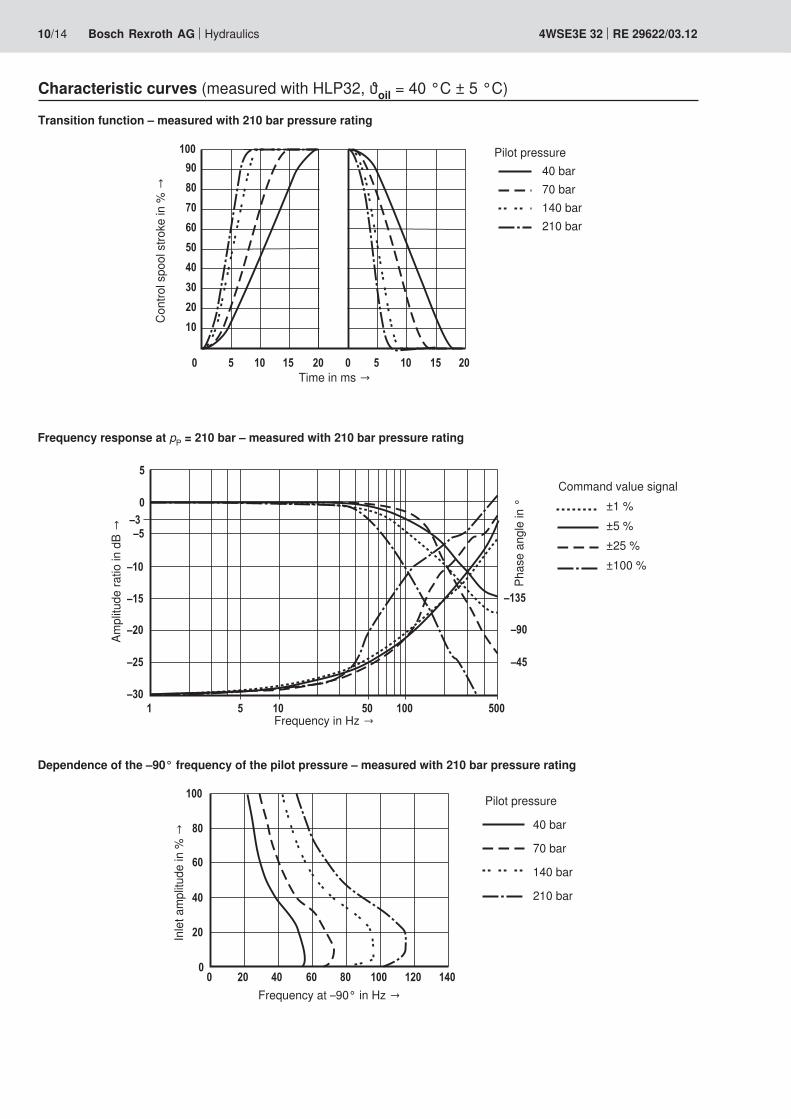
10/14 Bosch Rexroth AG Hydraulics 4WSE3E 32 RE 29622/03.12
Characteristic curves (measured with HLP32, ϑoil = 40 °C ± 5 °C)
Transition function – measured with 210 bar pressure rating
Frequency response at pP = 210 bar – measured with 210 bar pressure rating
Ampl
itude
ratio
in d
B →
Frequency in Hz →
Cont
rol s
pool
stro
ke in
% →
Time in ms →
Pilot pressure 40 bar 70 bar 140 bar 210 bar
Command value signal ±1 % ±5 % ±25 % ±100 %
Dependence of the –90° frequency of the pilot pressure – measured with 210 bar pressure rating
Inle
t am
plitu
de in
% →
Frequency at –90° in Hz →
Pilot pressure
40 bar
70 bar
140 bar
210 bar
Phas
e an
gle
in °

Hydraulics Bosch Rexroth AGRE 29622/03.12 4WSE3E 32 11/14
Characteristic curves (measured with HLP32, ϑoil = 40 °C ± 5 °C)
Transition function – measured with 315 bar pressure rating
Frequency response at pP = 315 bar – measured with 315 bar pressure rating
Ampl
itude
ratio
in d
B →
Frequency in Hz →
Cont
rol s
pool
stro
ke in
% →
Time in ms →
Pilot pressure 40 bar 70 bar 140 bar 210 bar 315 bar
Command value signal ±1 % ±5 % ±25 % ±100 %
Dependence of the –90° frequency of the pilot pressure – measured with 315 bar pressure rating
Inle
t am
plitu
de in
% →
Frequency at –90° in Hz →
Pilot pressure
40 bar
70 bar
140 bar
210 bar
315 bar
Phas
e an
gle
in °

12/14 Bosch Rexroth AG Hydraulics 4WSE3E 32 RE 29622/03.12
Unit dimensions: Type 4WSE3E 32 (dimensions in mm)
Required surface quality of the valve mounting face
1 Name plate – overall valve2 Name plate – pilot control valve3 Mating connector according to EN 175201-804,
separate order, see page 134 Space required to remove the mating connector,
take connection cable into account!5 PVC cable not resistant when in contact with HFD-R fluid6 Locating pin (2x) G1 and G27 Cover plate (for transport only)8 Pilot control valve (2-stage)9 Main stage (3rd stage)
10 Integrated control electronics11 Identical seal rings for ports A, B, P, and T12 Identical seal rings for ports X and Y
The ports X and Y are also pressurized in the case of "internal" pilot oil supply
13 Machined valve mounting face, porting pattern according to ISO 4401-10-09-0-05
14 Exchangeable filter element with seal, material no. R961000194
15 Valve mounting screws16 Hexagon nuts (for transport only)17 Ring bolts (for transport only)
Hexagon socket head cap screws (included in the scope of delivery) Material numberSize 32 6x ISO 4762 - M20 x 80 - 10.9-flZn-240h-L
Tightening torque MA = 340 Nm ±10 %R901035246
Notice: This tightening torque of the hexagon socket head cap screws refers to the maximum operating pressure!

Hydraulics Bosch Rexroth AGRE 29622/03.12 4WSE3E 32 13/14
Flushing plate with porting pattern according to ISO 4401-10-09-0-05 (dimensions in mm)
1 R-ring 19x3x3 (X, Y) included in scope of delivery2 R-ring 42.5x3x3 (P, T, A, B) included in scope
of delivery3 6 hexagon socket head cap screws
(included in scope of delivery)ISO4762-M20x90-10.9flZn-240h-L (friction coefficient 0.09 to 0.14 according to VDA 235-101) MA = 340 Nm Material no. R913000397
4 2 locating pins 6x12-6.8 DIN EN 287415 Name plate
Symbols
with FKM seals Material no. R900550597 Weight: 22.3 kg
To ensure proper operation of the servo-valves, it is necessary to flush the system before commissioning.The following values are guidelines for the flushing time per system: t = Flushing time in hours V = Tank capacity in liters qV = Pump flow in liters per minuteWhen topping up more than 10 % of the tank capac-ity, the flushing procedure must be repeated.The use of a directional valve with port in accor-dance with ISO 4401-10-09-0-05 is better suited than a flushing plate. With this valve, you can also flush the actuator ports.
with FKM seals Material no. R900959396 (without fig.) Weight: 22.3 kg
Accessories (not included in the scope of delivery)
Mating connectors Material numberMating connector for servo-valve DIN EN 175201-804, see data sheet 08006 R900223890 (metal)
Subplates Data sheetSize 32 45060
t ≥ ― • 5VqV

Bosch Rexroth AG HydraulicsZum Eisengießer 197816 Lohr am Main, Germany Phone +49 (0) 93 52 / [email protected] www.boschrexroth.de
© This document, as well as the data, specifications and other informa-tion set forth in it, are the exclusive property of Bosch Rexroth AG. It may not be reproduced or given to third parties without its consent.The data specified above only serve to describe the product. No state-ments concerning a certain condition or suitability for a certain applica-tion can be derived from our information. The information given does not release the user from the obligation of own judgment and verification. It must be remembered that our products are subject to a natural process of wear and aging.
14/14 Bosch Rexroth AG Hydraulics 4WSE3E 32 RE 29622/03.12
Notes

Bosch Rexroth AG HydraulicsZum Eisengießer 197816 Lohr am Main, Germany Phone +49 (0) 93 52 / [email protected] www.boschrexroth.de
© This document, as well as the data, specifications and other informa-tion set forth in it, are the exclusive property of Bosch Rexroth AG. It may not be reproduced or given to third parties without its consent.The data specified above only serve to describe the product. No state-ments concerning a certain condition or suitability for a certain applica-tion can be derived from our information. The information given does not release the user from the obligation of own judgment and verification. It must be remembered that our products are subject to a natural process of wear and aging.
Hydraulics Bosch Rexroth AGRE 29622/03.12 4WSE3E 32 15/14

Bosch Rexroth AG HydraulicsZum Eisengießer 197816 Lohr am Main, Germany Phone +49 (0) 93 52 / [email protected] www.boschrexroth.de
© This document, as well as the data, specifications and other informa-tion set forth in it, are the exclusive property of Bosch Rexroth AG. It may not be reproduced or given to third parties without its consent.The data specified above only serve to describe the product. No state-ments concerning a certain condition or suitability for a certain applica-tion can be derived from our information. The information given does not release the user from the obligation of own judgment and verification. It must be remembered that our products are subject to a natural process of wear and aging.
16/14 Bosch Rexroth AG Hydraulics 4WSE3E 32 RE 29622/03.12