4/27/2021 design criteria for permeable pavement
TRANSCRIPT

4/27/2021 Design criteria for permeable pavement - Minnesota Stormwater Manual
https://stormwater.pca.state.mn.us/index.php?title=Design_criteria_for_permeable_pavement 1/14
Design criteria for permeable pavementGreen Infrastructure: Permeable pavement can be an important tool for retention and detentionof stormwater runoff. Permeable pavement may provide additional benefits, including reducing theneed for de-icing chemicals, and providing a durable and aesthetically pleasing surface.
This section provides information on design considerations,criteria and specifications for permeable pavement.Base/subbase thickness is determined for water storage usinghydrologic sizing and/or dynamic modeling over time.Base/subbases thickness for supporting traffic is determinedusing structural design methods. The thicker of the tworesulting designs is employed.
Contents
1 Design phase maintenance considerations2 Hydrologic design considerations3 Design criteria
3.1 Structural design3.2 Outflow rate and volume through
underdrains3.3 Design for nutrient and TSS reductions3.4 Soil infiltration rate testing3.5 Conveyance and overflow3.6 Reservoir layer3.7 Underdrains3.8 Maintenance
4 Major design elements4.1 Minimum separation distance4.2 Setback distances4.3 Pretreatment4.4 Depth
5 Materials specifications6 Other design considerations
6.1 Karst terrain6.2 Winter considerations6.3 Signage
Schematic illustrating typical perviousconcrete cross section and basic componentsof a pervious concrete system.
Schematic illustrating typical porous asphaltcross section and basic components of apervious concrete system.
4/27/2021 Design criteria for permeable pavement - Minnesota Stormwater Manual
https://stormwater.pca.state.mn.us/index.php?title=Design_criteria_for_permeable_pavement 2/14
7 Design checklists8 Related articles
Design phase maintenanceconsiderations
Implicit in the design guidance is the fact that many designelements of infiltration and filtration systems can minimize themaintenance burden and maintain pollutant removal efficiency.Key examples include
limiting drainage area;providing easy site access (REQUIRED); andproviding pretreatment (REQUIRED).
For more information on design information for individual infiltration and filtration practices, link here (http://stormwater.pca.state.mn.us/index.php/Category:Design_criteria).
Hydrologic design considerations
Permeable pavement is subject to the following design considerations, including benefits and constraints.
Available space – A significant advantage of permeable pavement is its ability to combine detention/infiltration and pavement, thereby reducing or eliminating land required for detention facilities. This isespecially important in urban areas with high land prices and highly developed sites with little or no space forstormwater detention.
Soils – Soil conditions and infiltration rates determine the use of an underdrain. (NRCS (http://www.nrcs.usda.gov/wps/portal/nrcs/main/national/home) Hydrologic Soil Group (HSG) C or D soils usually require anunderdrain, whereas HSG A and B soils often do not.) Designers should evaluate existing soil propertiesduring initial site layout with the goal of configuring permeable pavement that conserves and protects soilswith the highest infiltration rates. In particular, areas of HSG A or B soils shown on soil surveys should beconsidered as primary locations for all types of infiltration practices.
Soil surveys and HSG classifications provide a general estimate of the soil's infiltration rate. Soil infiltrationrates can also be estimated from soil classifications per ASTM (http://www.astm.org/Standard/index.shtml)D2487. However, it is best to determine rates using on-site infiltration testing per ASTM D3385 StandardTest Method for Infiltration Rate of Soils in Field Using Double-Ring Infiltrometer, D5093 Standard TestMethod for Field Measurement of Infiltration Rate Using Double-Ring Infiltrometer with Sealed-Inner Ringor other available methods. The median rate determined from in-situ measurements should be reduced by afactor of 2.5 and this reduced value used in design calculations. This reduction accounts for incidentalcompaction during construction and sedimentation of the subgrade over time.
Information: The safety factor of 2.5 is greater than a factor of 2 recommended in most guidance for permeablepavement (see [1] (http://www.vwrrc.vt.edu/swc/NonPBMPSpecsMarch11/VASWMBMPSpec7PERMEABLEPAVEMENT.html), [2] (http://www.rwra.org/wp-content/uploads/2011/09/Stormwater-Fact-Sheets-Minimum-Standards.pdf), [3] (http://doee.dc.gov/sites/default/files/dc/sites/ddoe/publication/attachments/Ch3.4PermeablePavement_0.pdf), [4] (http://www.cambridgepavers.com/dfiles/PermPvtManual7_27.pdf), [5] (http://www.njstormwater.org/bmp_manual/NJ_SWBMP_9.7.pdf)). This manual utilizes recommended soil infiltration rates for hydrologic soil groups(see [6] (http://stormwater.pca.state.mn.us/index.php/Design_infiltration_rates)). These are not as conservative as
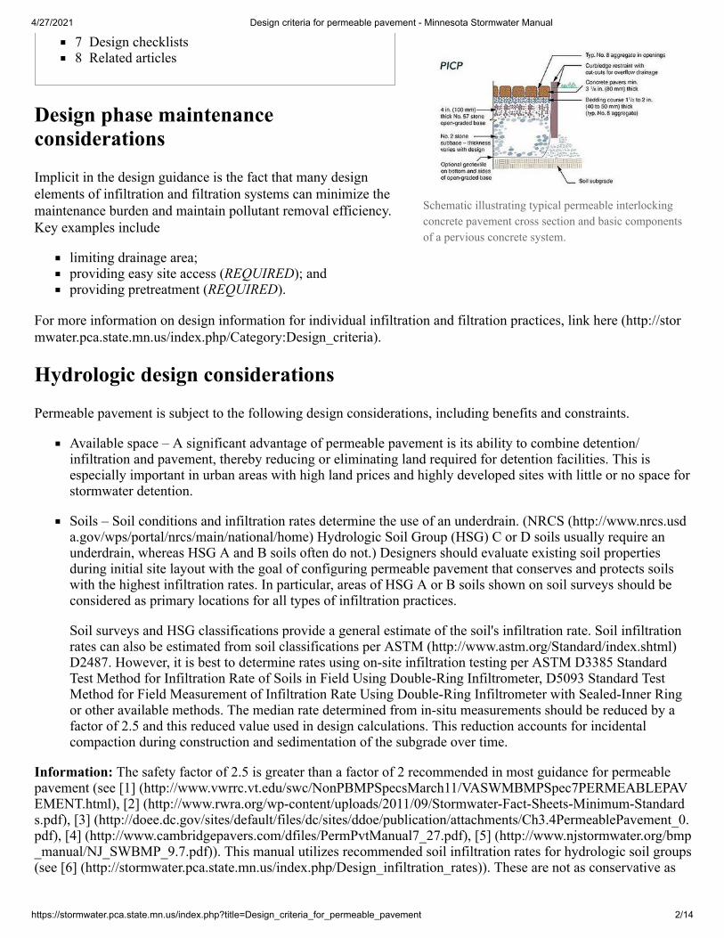
Schematic illustrating typical permeable interlockingconcrete pavement cross section and basic componentsof a pervious concrete system.

4/27/2021 Design criteria for permeable pavement - Minnesota Stormwater Manual
https://stormwater.pca.state.mn.us/index.php?title=Design_criteria_for_permeable_pavement 3/14
infiltration rates based on the Unified Soil Classification System (https://www.pca.state.mn.us/sites/default/files/p-gen3-12d.pdf), particularly for finer textured soils. We therefore recommended the more conservative value of 2.5
In most cases, permeable pavement should not be situated above fill soils. Designs in compacted fill soilsmay require an impermeable liner and an underdrain. Permeable pavements should only be placed on fillsoils when laboratory tests indicate the compacted fill will be stable when saturated and that slope stability ofdeep fills has been verified by a geotechnical engineer.
Geotextiles - In the absence of full-depth concrete curbs or impermeable liners, geotextiles are recommendedon the (vertical) sides of permeable pavements to separate the reservoir layers from the adjacent soilsubgrade. Horizontally placed geotextiles between the aggregate base and soil subgrade are at the option ofthe designer. Geotextile use should be carefully evaluated and selection should be guided by AASHTO M-288 Geotextile for Highway Applications (AASHTO 2010). Specific selection guidance is provided under theSubsurface Drainage section. Class II geotextiles are generally used.
Contributing drainage area – Permeable pavements sometimes capture runoff from adjacent areas,pavements, and roofs. Runoff from permeable areas is not recommended due to potential clogging of thepermeable pavement. The at-grade contributing drainage area into permeable pavement should generally notexceed twice the surface area of the permeable pavement. This guideline helps reduce the rate of surfacesedimentation. The 2:1 ratio can be increased to no greater than 5:1 if at least one of these conditions exists:
permeable pavement is receiving runoff from roofs as it tends to be very low in sediment; orrunoff from adjacent impervious surfaces remains unburdened with sediment due to effective pre-treatment prior to entering the permeable pavement.
For more information on contributing area, see Contributing drainage area to stormwater BMPs.
Caution: Permeable pavement and contributing impervious pavements are assumed to receive regular vacuumingto reduce and control sediment loads and surface clogging potential.
Soil subgrade slope – The slope of the soil subgrade should be as flat as possible (i.e., less than 1 percentlongitudinal slope) to enable even distribution and infiltration of stormwater. Lateral slopes should be lessthan 1 percent. Steep slopes can reduce the stormwater storage capacity of permeable pavement. Designersshould consider using a terraced subgrade design for permeable pavement in sloped areas, especially whenthe subgrade slope exceeds 3 percent.
Soil subgrade compaction – This should be avoided wherever possible to maximize infiltration. In somesituations, compaction may be needed for supporting vehicular loads. In such cases, compaction density andsubsequent soil infiltration should be assessed in a test pit(s) on the site to determine an acceptable soildensity and its contribution to soil strength and infiltration. The measured infiltration rate for use inhydrologic calculations may be reduced by the designer to compensate for long-term sedimentation on thesoil subgrade.
Excavation methods - Excavation should be conducted in a manner that minimizes soil subgrade compaction.Tracked rather than wheeled equipment is recommended working from the sides of the excavation. For largerprojects, excavation can create cells and berms where equipment removes soil from one area or cell whilepositioned on higher soil around each cell (see Construction specifications for permeable pavement). Othertechniques include ripping or loosening soils compacted by construction equipment. This can be done withthe teeth on excavation equipment buckets. Compaction of the aggregate base into these areas is especiallyimportant since scarified soil can settle and be reflected on the surface.
Surface slope – Surface slopes for all permeable pavement types should be at least 1 percent to provide analternate means for drainage should the surface become completely clogged due to lack of maintenance.Designs should provide an alternate means for stormwater to enter the aggregate reservoir if the pavementsurface should ever become clogged, or for extreme storm events. For pervious concrete and porous asphalt

4/27/2021 Design criteria for permeable pavement - Minnesota Stormwater Manual
https://stormwater.pca.state.mn.us/index.php?title=Design_criteria_for_permeable_pavement 4/14
without curbs, this can be a 2 foot wide stone edge connected to the reservoir. For curbed pavements, inletsmay be used.
Overflow structures – Permeable pavements are not designed to store and infiltrate all stormwater from allstorms. Therefore, an outlet or outlets are required to prevent water from rising into and over the surface. Onetype of outlet control would be a catch basin with an internal weir and low-flow orifice. The catch basin canalso handle runoff from the surface should it become clogged.
Minimum depth to seasonal high water table – A high groundwater table may cause seepage into the bottomof permeable pavement and prevent complete drainage. Also, soil acts as a filter for pollutants between thebottom of the pavement base and the water table. Therefore, a minimum vertical separation of 3 feet isrequired between the bottom of the permeable pavement reservoir layer and the seasonal high groundwatertable. For systems with impermeable liners, a minimum of one foot clearance is Highly recommendedbetween the liner and the seasonal high water table.
Setbacks – To avoid harmful seepage, permeable pavement should not be hydraulically connected to buildingfoundations unless an impermeable liner is placed against the foundation or basement wall. Even under thesecircumstances, great care should be taken to avoid creating a wet basement problem. If there is no liner, thepermeable pavement base should be 10 feet or greater from structures (EPA recommends a minimum setbackfrom building foundations of 10 feet down-gradient and 100 feet up-gradient. See EPA factsheet “StormWater Technology Fact Sheet: Porous Pavement,” EPA 832-F-99-023 (http://www.cleanwatermn.org/Documents/MS4%20toolkit%20files/Good%20Housekeeping/Porous%20Pavement/porouspa.pdf)). Again, it is thedesigner’s responsibility to avoid creating a wet basement problem. Likewise, permeable pavement basesshould be hydraulically separated from adjacent road bases.
Permeable pavements without underdrains infiltrate stormwater and should follow requirements for wellheadprotection (EPA recommends a minimum setback of 100 feet from water supply wells). Underground utilitylines are best located away from permeable pavement bases. However, if they need to penetrate the base,consideration should be given to waterproofing (depending on the utility) or possible encasement using low-strength flowable concrete fill. Setbacks can be reduced at the discretion of the local authority for designs thatuse underdrains and/or liners.
Informed Owner – The property owner should clearly understand the unique maintenance responsibilitiesinherent with permeable pavement, particularly for parking lot applications. The owner should be capable ofperforming routine and long-term actions (e.g., vacuuming) to maintain the pavement’s hydrologic functions,and avoid future practices (e.g., winter sanding, seal coating or repaving) that diminish or eliminate them. Forporous asphalt a diluted emulsion fog can be used as needed. Maintenance agreements, covenants,maintenance easements or performance bonds are encouraged between the local authority and the propertyowner.
Green Infrastructure: Permeable pavement can be used at highly developed urban sites that have little or no spaceretention.Caution: The required setback distance to a municipal water supply well is 50 feet, but it is recommended thatpermeable pavements be a minimum horizontal distance of 100 feet from any municipal water supply wellWarning: A minimum vertical separation of 3 feet is required between the bottom of the permeable pavementreservoir layer and the seasonal high groundwater table (saturated soil) or the top of bedrock (i.e. there must be aminimum of 3 feet of undisturbed soil beneath the infiltration practice and the seasonally high water table or top ofbedrock).
Limitations – There are several limitations for use of permeable pavement, as summarized below.Permeable pavements should not be used in high pollutant loading sites. High pollutant loading sitesare those that receive constant sediment or trash and/or debris. Places where fuels and chemicals arestored or handled can be potential stormwater hotspots and permeable pavement should not beconstructed in these places. Likewise, areas subject to wind borne dust and sediment should not use

4/27/2021 Design criteria for permeable pavement - Minnesota Stormwater Manual
https://stormwater.pca.state.mn.us/index.php?title=Design_criteria_for_permeable_pavement 5/14
permeable pavement unless the pavement can be vacuumed regularly. The following limitations shouldbe considered before utilizing permeable pavements in any design.Permeable pavement is suitable for pedestrian-only areas, low-volume roads, low speed areas,overflow parking areas, residential driveways, alleys, and parking stalls. These can be residentialcollector roads or other applications with similar traffic loads.Permeable pavement can be prone to clogging from sand and fine sediments that fill void spaces andthe joints between pavers. As a result, it should be used carefully where frequent winter sanding isnecessary because the sand may clog the surface of the material. Periodic maintenance is critical, andsurfaces should be cleaned with a vacuum sweeper at least two times a year.Fuel may leak from vehicles and toxic chemicals may leach from asphalt and/or binder surface. Porouspavement systems are not designed to treat these pollutants.
Design criteria
Base/subbase thickness is determined for support traffic using structural design methods and for water storage usinghydrologic sizing and/or dynamic modeling over time. The thicker of the two resulting designs is used.
Structural design
The structural design process for supporting vehicles varies according to the type of pavement selected. Thepervious concrete industry is in the process of developing ASTM test methods for characterizing compressive orflexural strengths of pervious concrete. These tests are needed to model fatigue under loads. As an interim step,fatigue equations published by the American Concrete Pavement Association (ACPA (http://www.pavement.com/)2010) assume such inputs to be comparable in nature (but not magnitude) to those used for conventional concretepavements. The ACPA design method should be consulted for further information as well as pervious concreteindustry software. General guidelines for pervious concrete surface thickness are published by the National ReadyMix Concrete Association NRMCA (http://www.nrmca.org/) and the Portland Cement Association (Leming (http://www.rmc-foundation.org/images/PCRC%20Files/Hydrological%20&%20Environmental%20Design/PC_DesignManual.pdf) 2007).
Porous asphalt (Hansen 2008) and permeable interlocking pavements (Smith 2011) use flexible pavement designmethods adopted from the 1993 AASHTO Guide for Design of Pavement Structures (AASHTO 1993). In addition,MnDOT design methods, approved mechanistic principles, and manufacturer’s specific recommendations should beconsulted.
There has been limited research on full-scale testing of the structural behavior of open-graded bases used underpermeable pavements to better characterizing relationships between loads and deformation. Therefore, conservativevalues (i.e., AASHTO layer coefficients) should be assumed for open-graded base and subbase aggregates inpermeable pavement design.
Regardless of type of permeable pavement, structural design methods consider the following in determining surfaceand base thicknesses to support vehicular traffic:
pavement life and total anticipated traffic loads expressed as 18,000 pounds equivalent single axle loads orESALs (This method of assessing loads accounts for the additional pavement wear caused by trucks.);soil strength expressed as the soaked California Bearing Ratio (CBR), R-value or resilient modulus (Mr);strength of the surfacing, base and subbase materials; andenvironmental factors including freezing climates and extended saturation of the soil subgrade.
Soil stability under traffic should be carefully reviewed for each application by a qualified geotechnical or civilengineer and lowest anticipated soil strength or stiffness values under saturated conditions used for design.Structural design for vehicular applications should generally be on soil subgrades with a CBR (96-hour soaked per

4/27/2021 Design criteria for permeable pavement - Minnesota Stormwater Manual
https://stormwater.pca.state.mn.us/index.php?title=Design_criteria_for_permeable_pavement 6/14
ASTM D 1883 or AASHTO T 193) of 4 percent, or a minimum R-value = 9 per ASTM D 2844 or AASHTO T-190,or a minimum Mr of 6,500 pounds per square inch (45 Mega Pascals) per AASHTO T-307. Soils with lowerstrengths typically require thickened permeable bases or those using cement or asphalt stabilized open-gradedaggregates per Mn/DOT Pavement Manual (http://www.dot.state.mn.us/materials/pvmtdesign/), Section 3-3.01.02Treated Base.
Soil compaction required to achieve these soil strengths will reduce the infiltration rate of the soil. Therefore, thepermeability or infiltration rate of soil should be assessed at the density required to achieve one of these values. Ifsoils under vehicular traffic have lower strengths than those noted above, or are expansive when wet, there areseveral options, including
underdrains;thickened base/subbase layer(s);cement or asphalt stabilized base layers; andlime or cement stabilized (with design consideration given to practically no infiltration in such cases).
These options are typically used in combination. Pedestrian applications can be placed on lower strength soils thanthose noted.
Pedestrian applications can be placed on lower strength soils than those noted.
Outflow rate and volume through underdrains
If the depth of the base/subbase for the full infiltration system is excessive, because, as an example, the designsubgrade soil infiltration rate is not adequate to remove the water from the design storm within the designatedperiod of time, then the design should include underdrains. The following procedure is for sizing the base/subbasefor partial infiltration designs (i.e. contains underdrains).
The outflow rate from underdrain(s) can be approximated by
where
qu = outflow through underdrain, feet/hourk = Coefficient of permeability for each 6 inch diameter underdrain, feet/hourm = underdrain pipe slope, feet/feet
This equation is based on Darcy’s Law, which summarizes several properties that groundwater exhibits whileflowing in aquifers. Although the hydraulic conductivity (measure of the ease with which water can move throughpore spaces of a material) of the aggregate subbase is very high (approximately 17,000 feet per day or 8,500 inchesper hour), the discharge rate through underdrains is limited by the cross sectional area of the pipe. As the storagevolume above/around the underdrain(s) decreases (i.e., the hydraulic head or water pressure decreases), thebase/subbase and in turn the underdrain(s) will drain increasingly slower. To account for this change in flowconditions within the subbase and underdrain(s) over time, a very conservative coefficient of permeability (k) of100 feet per day per pipe can be used to approximate the average underdrain outflow rate.
Once the outflow rate through each underdrain has been approximated, the depth of the base/subbase needed tostore the design storm can be determined by
where
= kmqu
= ((0.95 ∗ RP )– (i/2) ))/ndp tf

4/27/2021 Design criteria for permeable pavement - Minnesota Stormwater Manual
https://stormwater.pca.state.mn.us/index.php?title=Design_criteria_for_permeable_pavement 7/14
0.95 is the runoff coefficient for impermeable surfaces;dp = the depth of the reservoir layer (feet);R = Ac/Ap The ratio of the contributing drainage area (Ac, including the permeable paving surface), to thepermeable pavement surface area (Ap);tf = the time to fill the reservoir layer (day) – typically 2 hours or 0.083 day;P = the rainfall depth for the design storm (feet);i = field-verified infiltration rate (ft/day); andn = porosity (cubic feet/cubic feet)
To estimate the number of underdrain pipes (N), take the dimension of the parking lot in the direction the pipes areto be placed and divide by the desired spacing between pipes – round down to the nearest whole number.
With full infiltration systems, the maximum allowable drain time (td) needs to be calculated to make sure the storedwater within the base/subbase does not take too long to infiltrate into the soil subgrade.
The total storage in the permeable pavement system, Vs, is given by
where
Ap is the surface area of the permeable pavement (ft2).
When calculating the storage volume for compliance with the Construction Stormwater Permit, only theinstantaneous storage volume is considered
Permeable pavement can also be designed to augment detention storage needed for channel protection and/or floodcontrol. The designer can model various approaches by factoring in storage within the base/subbase, expectedinfiltration and any outlet structures used as part of the design.
Once runoff passes through the surface of the permeable pavement system, designers should calculate outflowpathways to handle subsurface flows. Subsurface flows can be regulated using underdrains, the volume of storagein the reservoir layer, the bed slope of the reservoir layer, and/or a control structure at the outlet.
Design for nutrient and TSS reductions
Permeable pavements can be designed to reduce nutrient loadings to the ground or surface waters. The design needsto be specifically designed to capture phosphorus. The permeable pavement system can also be designed to capturenitrogen, although it is important to note that nitrogen and phosphorus each require specific designs to facilitatetheir removal from stormwater. The following paragraphs describe the design characteristics necessary for theremoval of phosphorus and nitrogen.
A study by (Bean, 2007a) showed higher nitrate concentrations in the exfiltrate compared to the infiltrate. Nitrogenreduction capabilities of permeable pavement can be enhanced in partial infiltration designs that detain water in thebase/subbase for over 24 hours. This time is required to ensure complete de-nitrification occurs.
PICP can use specially coated aggregates in the joints and bedding and all systems can use them in the base toreduce phosphorous. Coated aggregates (sometimes called “engineered aggregates”) have an effective life of sevento ten years and target the removal of dissolved phosphorous, according to manufacturer’s literature.
td = ( n)/(0.5i)dp
= ( n + 0.5i )Vs Ap dp tf
= ( n)Vs Ap dp

4/27/2021 Design criteria for permeable pavement - Minnesota Stormwater Manual
https://stormwater.pca.state.mn.us/index.php?title=Design_criteria_for_permeable_pavement 8/14
A filter layer made of sand or fine aggregate placed under or sandwiched within permeable pavement bases areoccasionally used as a means to reduce nutrients. This layer can be enhanced with iron filings for phosphorousreduction (Erickson 2010). Their effectiveness, initial cost, reduction in flow rates, and maintenance costs should beweighed against other design options for nutrient reductions. Sand filters will incur additional construction expenseand this can be reduced by placing sand filters under the subbase at the down slope end of a permeable pavement.The disadvantage of sand filters is that they will eventually require removal and restoration if continued phosphorusreduction credit is desired. Concentrating their location in the down slope areas of the site can help reduce futuremaintenance costs and site disruptions.
A second approach useful for nutrient and TSS reduction can occur on sloping sites by creating intermittent bermsin the soil subgrade. These enable settlement of suspended solids and encourage de-nitrification if appropriatelydesigned. A third alternative is using a “treatment train” approach where a permeable pavement initially filtersrunoff and the remaining water outflows to bioswales or rain gardens adjacent to the pavement for additionalprocessing and nutrient reduction. There may be additional BMPs used to remove nutrients as the water movesthrough the watershed.
Soil infiltration rate testing
Prior to infiltration testing, soil borings should be taken with an auger to assess the consistency of the soil type andhorizons. Guidance for conducting infiltration tests and for determining the number of borings can be found here (http://stormwater.pca.state.mn.us/index.php/Design_criteria_for_bioretention#Determine_site_infiltration_rates_.28for_facilities_with_infiltration_and.2For_recharge.29).
Conveyance and overflow
Permeable pavement designs should include methods to convey larger storms (e.g., 2-year, 10-year) to the stormdrain system. The following is a list of methods that accomplish this.
Place a perforated pipe horizontally near the top of the reservoir layer to pass excess flows after water hasfilled the base. The placement and/or design should be such that the incoming runoff is not captured (e.g.,placing the perforations on the underside only). Pipe placement should be away from wheel loads to preventdamage.Increase the thickness of the top of the reservoir layer.Create underground detention within the reservoir layer of the permeable pavement system. Reservoir storagemay be augmented by corrugated metal pipes, plastic or concrete arch structures, etc.Route excess flows to another detention or conveyance system that is designed for management of extremeevent flows.Set the storm drain inlets level with the elevation of the permeable pavement surface to effectively conveyexcess stormwater runoff past the system. The design should also make allowances for relief of unacceptableponding depths during larger rainfall events.
Reservoir layer
The reservoir below the permeable pavement surface should be composed of clean, washed crushed stone aggregateand thickness sized for both the storm event to be stored and the structural requirements of the expected trafficloading. The recommended minimum void ratio should be 40 percent per ASTM (http://www.astm.org/) C29.Reservoir base layers for pervious concrete are typically washed AASHTO No. 57 stone and those for porousasphalt are AASHTO (http://www.transportation.org/Pages/default.aspx) No. 2, 3, or 5. PICP uses AASHTO No. 2,3, or 4 stone.

4/27/2021 Design criteria for permeable pavement - Minnesota Stormwater Manual
https://stormwater.pca.state.mn.us/index.php?title=Design_criteria_for_permeable_pavement 9/14
If exposed to vehicular loads, all crushed stone should be Minnesota Department of Transportation (MnDOT) ClassA or B coarse aggregate, minimum 80 percent crushed, typically granite, basalt, gneiss, trap rock, diabase, gabbro,or similar material. The maximum Los Angeles Rattler Loss (http://www.dot.state.mn.us/materials/manuals/laboratory/1210.pdf) should be 35 percent per AASHTO T-96 and no greater loss than 10 percent per AASHTO T-104Magnesium Sulfate Soundness Test on the non-igneous portions and as modified by the MnDOT LaboratoryManual (http://www.dot.state.mn.us/materials/labmanual.html) (MNDOT 2005). Limestone aggregates not meetingthese requirements are not recommended in vehicular applications. Class C and D aggregates may be used in areassubject only to pedestrian traffic.
Underdrains
Underdrains install quickly when placed on or in the soil subgrade, surrounded by stone base materials. Theoutflow portion at the end is not perforated and is raised to a designed height that allows for some water detentionprior to outflow. Placement at this elevation also protects the pipe with aggregate during base compaction. Forpermeable pavement bases/subbases using 2 or 3 inch maximum size aggregates, underdrain pipes with themshould be surrounded with at least 4 inches of ASTM No. 57 (maximum 1 inch size aggregate) to protect the pipesduring compaction. An underdrain(s) can also be installed and capped at a downstream structure as an option forfuture use if maintenance observations indicate a reduction in the soil permeability.
Maintenance
Proper maintenance of permeable pavement is crucial for ensuring its longevity and functionality. Some portions ofthe maintenance plan require planning during the design stages. These items are noted below.
Observation Well – Typically this consists of a well-anchored, six-inch diameter perforated PVC pipe thatextends vertically to the bottom of the reservoir layer. This is installed at the down slope end of the permeablepavement. The observation well should be fitted with a lockable cap installed flush with the ground surface(or under the pavers) to facilitate periodic inspection and maintenance. The observation well enables visualmonitoring of drawdown within the reservoir layer after a storm.Overhead Landscaping – Some communities require a certain percentage of parking lots to be landscaped.Large-scale permeable pavement should be carefully planned to integrate landscaping in a manner thatmaximizes runoff treatment and minimizes risk of sediment, mulch, grass clippings, crushed leaves, nuts, andfruits inadvertently clogging the surface. Prior to construction, owners should commit to a vacuuming planthat includes vacuuming frequency and equipment needs. The vacuuming frequency typically depends on thetime of year. In the spring, tree buds and seeds necessitate frequent vacuuming. In the fall, tree leaves andacorns necessitate frequent vacuuming. In the summer, vacuuming frequency depends on permeablepavement exposure to organic material from trees and nearby vegetated areas. Vacuum equipment andmethods for sediment removal are provided in the section addressing operation and maintenance.
Major design elements
The following design elements apply to permeable pavement.
Minimum separation distance
Warning: It is REQUIRED that infiltration practices be designed with a minimum vertical distance of 3 feetbetween the bottom of the infiltration practice and the seasonally high water table or bedrock layer. See also Step 8under the Design procedures section.
Local authorities may require greater separation depths.

4/27/2021 Design criteria for permeable pavement - Minnesota Stormwater Manual
https://stormwater.pca.state.mn.us/index.php?title=Design_criteria_for_permeable_pavement 10/14
It is HIGHLY RECOMMENDED that infiltration practices not be hydraulically connected to structure foundationsor pavement, to avoid seepage and frost heave concerns, respectively. If groundwater contamination is a concern, itis RECOMMENDED that groundwater mapping be conducted to determine possible connections to adjacentgroundwater wells.
Setback distances
Warning: The minimum setback distance from a stormwater infiltration system to a public water-supply well is100 feet for wells classified as sensitive and 50 feet for all other public supply wells, as REQUIRED by theMinnesota Department of Health. See MDH isolation distances (http://www.health.state.mn.us/divs/eh/wells/construction/isolate.html) (pollutant or contaminant that may drain into the soil)Caution: The minimum setbacks in the table below are HIGHLY RECOMMENDED for the design and location ofinfiltration practices. It will be necessary to consult local ordinances for further guidance on siting infiltrationpractices.
Required and recommended minimum vertical and horizontal separation distances. This represents theminimum distance from the infiltration practice to the structure of concern. If the structure is above-ground,the distance is measured from the edge of the BMP to the structure. If the structure is underground, thevertical separation distance represents the distance from the point of infiltration through the bottom of thesystem to the structure, while the horizontal separation (often called setback) distance is the shortest distancefrom the edge of the system to the structure. Link to this table
Structure Distance(feet)
Requirement orrecommendation Note(s)
Vertical
Saturated soil (https://stormwater.pca.state.mn.us/index.php?title=Shallow_groundwater)
3 Requirement1
Bedrock (https://stormwater.pca.state.mn.us/index.php?title=Shallow_soils_and_shallow_depth_to_bedrock)
3 Requirement1
Horizontal
Public supply well
100 forsensitivewells; 50 forothers
Requirement
Building/structure/property line2 10 Recommended
Surface water
none unlesslocalrequirementsexist
If nearby stream is impairedfor chloride, see [7] (http://stormwater.pca.state.mn.us/index.php/Stormwater_infiltration_and_setback_%28separation%29_distances#Surface_waters)
Septic system 35 RecommendedContaminated soil/groundwater (https://stormwater.pca.state.mn.us/index.php?title=Stormwater_infiltration_and_contaminated_soils_and_groundwater)
No specific distance.Infiltration must not mobilizecontaminants.
Slope 200 Recommended from toe of slope >= 20%

4/27/2021 Design criteria for permeable pavement - Minnesota Stormwater Manual
https://stormwater.pca.state.mn.us/index.php?title=Design_criteria_for_permeable_pavement 11/14
Structure Distance(feet)
Requirement orrecommendation Note(s)
Karst
1000 up-gradient 100down-gradient
Requirement1 Active karst
1 Required under the Construction Stormwater General Permit 2 Minimum with slopes directed away from the building
Karst: It is HIGHLY RECOMMENDED that infiltration practices not be used in active karst formations withoutadequate geotechnical testing.
Wellhead Protection Areas: It is HIGHLY RECOMMENDED to review the Minnesota Department of Healthguidance (http://www.health.state.mn.us/divs/eh/water/swp/stormwater.pdf) on stormwater infiltration in WellheadProtection Areas.
Pretreatment
Warning: It is REQUIRED that some form of pretreatment, such as a plunge pool, sump pit, filter strip,sedimentation basin, grass channel, or a combination of these practices be installed upstream of the infiltrationpractice.
It is HIGHLY RECOMMENDED that the following pretreatment sizing guidelines be followed:
Before entering an infiltration practice, stormwater should first enter a pretreatment practice sized to treat aminimum volume of 25 percent of the Vwq.If the infiltration rate of the native soils exceeds 2 inches per hour a pretreatment practice capable of treatinga minimum volume of 50 percent of the Vwq should be installed.If the infiltration rate of the native soils exceeds 5 inches per hour a pretreatment practice capable of treatinga minimum volume of 100 percent of the Vwq should be installed.
It is HIGHLY RECOMMENDED that pretreatment practices be designed such that exit velocities from thepretreatment systems are non-erosive (less than 3 feet per second) and flows are evenly distributed across the widthof the practice (e.g., by using a level spreader).
Depth
The depth of an infiltration practice is a function of the maximum drawdown time and the design infiltration rate.
Warning: The REQUIRED drawdown time for infiltration practices is 48 hours or less, and so the depth of thepractice should be determined accordingly.Warning: Groundwater Protection: It is REQUIRED that runoff from potential stormwater hotspots (PSHs) notbe infiltrated unless adequate pretreatment has been provided. Infiltration of runoff from confirmed hotspot areas,industrial areas with exposed significant materials, or vehicle fueling and maintenance areas is PROHIBITED.
Materials specifications
Permeable pavement material specifications vary according to the specific pavement product selected. Thefollowing table describes general material specifications for the components installed beneath the permeablepavement. Note that the size of stone materials used in the reservoir and filter layers differ depending whether thesystem is pervious concrete, porous asphalt or permeable interlocking concrete pavement.

4/27/2021 Design criteria for permeable pavement - Minnesota Stormwater Manual
https://stormwater.pca.state.mn.us/index.php?title=Design_criteria_for_permeable_pavement 12/14
Summary of specifications for materials under the pavement surface. For more information, see the footnote(1). Reference or links to any specific commercial product, process, or service by trade name, trademark,service mark, manufacturer, or otherwise does not constitute or imply endorsement, recommendation, orfavoring by the Minnesota Pollution Control Agency. Link to this table
Material Specification Notes
Bedding/chokerlayer
Pervious concrete: NonePorous asphalt: 1inch of AASHTO No.57 stonePICP: 2 inches of AASHTO (http://www.transportation.org/Pages/default.aspx) No. 8 stone (MnDOT 3127FA-3 (http://www.dot.state.mn.us/pre-letting/spec/2005/3101-3491.pdf))
Washed free of fines
Reservoir Layer
Pervious concrete: AASHTO No. 57stone or per hydraulic designPorous asphalt:AASHTO No. 2, 3, or 5stonePICP: 4 inches of AASHTO No. 57base and AASHTO No.2, 3 or 4 stonesubbase
Stone layer thickness based on the pavementstructural and hydraulic requirements.Stonewashed and free of fines. Recommendedminimum void ratio = 0.4.
Underdrain(optional)
Use 4 to 6 inch diameter perforated PVC (AASHTO M-252) pipe or corrugated polyethylenepipe. Perforated pipe installed for the full length of the permeable pavement cell, and non-perforated pipe, as needed,connected to storm drainage system.
Filter Layer(optional)
Sand filter layeris separated from base aboveand native soils with geotextile. Sand layertypically ASTM (http://www.astm.org/) C33gradation, 6 to 12 inches thick.
The Filter Layer is REQUIRED if using thepermeable pavement system to meet permitrequirements. The sand layer may require achoker layer on surface to provide transition tobase layerstone.
Geotextile(optional)Comply with AASHTO M-288 Standard Specification for Geotextile Specification forHighway Applications, drainage and separation applications, Class I or II. Porous asphaltindustry recommends non-woven geotextile.
Impermeable Liner Use a minimum 30mil PVC liner covered by 12 ounce/square yard non-woven geotextile.EPDM and HDPE liner material is also acceptable.
Observation Well Use a perforated 4 to 6 inch vertical PVC pipe (AASHTO M-252) with a lockable cap,installedflush with the surface (or under pavers).
1for additional information on materials referenced in this table (e.g. stone dimensions), see the following links:
stone size 1 (http://laurelaggregates.com/stone-types), 2 (see Table 1) (ftp://ftp.dot.state.fl.us/lts/CO/Specifications/SpecBook/2010Book/901.pdf)definitions of aggregates 1 (ftp://ftp.dot.state.fl.us/lts/CO/Specifications/SpecBook/2010Book/901.pdf)information on geotextiles 1 (ftp://ftp.wfl.fhwa.dot.gov/geotech/Geotech%20FP-12/207,%20714%20-%20Geosynthetics/AASHTO%20M-288%20spec%20%28DAN%29.pdf), 2 (http://www.tencate.com/amer/Images/TN_aashto0608_tcm29-16706.pdf)liners 1 (http://stormwater.pca.state.mn.us/index.php/Liners_for_stormwater_management)

4/27/2021 Design criteria for permeable pavement - Minnesota Stormwater Manual
https://stormwater.pca.state.mn.us/index.php?title=Design_criteria_for_permeable_pavement 13/14
A general comparison of different permeable pavements is provided in the following table. Designers shouldconsult industry association and manufacturer’s technical specifications for specific criteria and guidance.
This table shows summarizes specifications for permeable pavement. Link to this table.
Material Specification Notes
PermeablePavers
Surface open area: typically 5% to15%; minimum thickness: 3 inches forvehicles; minimum compressivestrength: 8,000 psi
Concrete pavers conform to ASTM C936 and clay paversC1272. Reservoir layer required to support the structuralload.
PerviousConcrete
Void content: 15% to 35 %Thickness: typically 5 to 8 inches
May not require a reservoir layer to support loads, but a layeris required for storage/infiltration. In no case should plainsteel rebar or mesh be used in pervious concrete as thisinvites corrosion.
PorousAsphalt
Void content: 16% to 20 %Thickness: minimum 2.5 inchsurface
Reservoir layer contributes to structural load support.
Other design considerations
There are additional design considerations for permeable pavement, including use of permeable pavement in karstterrain and winter considerations.
Karst terrain
A detailed geotechnical investigation may be required for any kind of stormwater design in karst terrain. Permeablepavements, as with other infiltration practices, are not recommended at sites with known karst features as they cancause the formation of sinkholes and can provide a direct link for stormwater to access groundwater withoutproviding any treatment.
Winter considerations
Plowed snow piles should be located in adjacent grassy areas so that sediments and pollutants in snowmelt arepartially treated before they reach all permeable pavements. Sand is not recommended for winter traction overpermeable pavements. If sand is applied, it must be removed with vacuum cleaning in the spring. Traction can beaccomplished on PICP using jointing stone materials, some of which will find its way into the joints by springtime.A significant winter advantage of permeable pavements is that they require less deicing materials than theirimpervious counterparts. Use of deicing material on permeable pavement is therefore not recommended.
Signage
Permeable pavements can be used as opportunities for public education with signs explaining how they work.Infiltration demonstrations also help show how the pavements work. Signs provide a reminder to maintenancecrews of their presence and list maintenance do’s and don’ts specific to the permeable pavement type.

4/27/2021 Design criteria for permeable pavement - Minnesota Stormwater Manual
https://stormwater.pca.state.mn.us/index.php?title=Design_criteria_for_permeable_pavement 14/14
Design checklists
Design checklists have not been developed for the Minnesota Stormwater Manual. We anticipate developing thesein 2018. Below are links to checklists developed by other organizations.
Iowa Stormwater Education Partnership, Permeable Paver Design Review Checklist (http://www.iowastormwater.org/documents/filelibrary/files/rainscaping_iowa/checklists/Permeable_Pavement_72516_1D67FA1EB1EBE.pdf)Cartegraph, Permeable Pavement Design Review checklist (https://www.slideshare.net/Cartegraph/permeable-pavement-check-list)
Related articles
Overview for permeable pavementTypes of permeable pavementDesign criteria for permeable pavementConstruction specifications for permeable pavementAssessing the performance of permeable pavementOperation and maintenance of permeable pavementCalculating credits for permeable pavementCase studies for permeable pavementGreen Infrastructure benefits of permeable pavementSummary of permit requirements for infiltrationPermeable pavement photo galleryAdditional considerations for permeable pavementLinks for permeable pavementReferences for permeable pavementFact sheets for permeable pavementRequirements, recommendations and information for using permeable pavement BMPs in the MIDScalculator
Permeable pavement main page (https://stormwater.pca.state.mn.us/index.php?title=Permeable_pavement)
Retrieved from "https://stormwater.pca.state.mn.us/index.php?title=Design_criteria_for_permeable_pavement&oldid=42694"
Search
This page was last edited on 3 June 2019, at 14:47.
Template:Footer
© 2021 by Minnesota Pollution Control Agency • Powered by MediaWiki