425 7-fans 2006
TRANSCRIPT
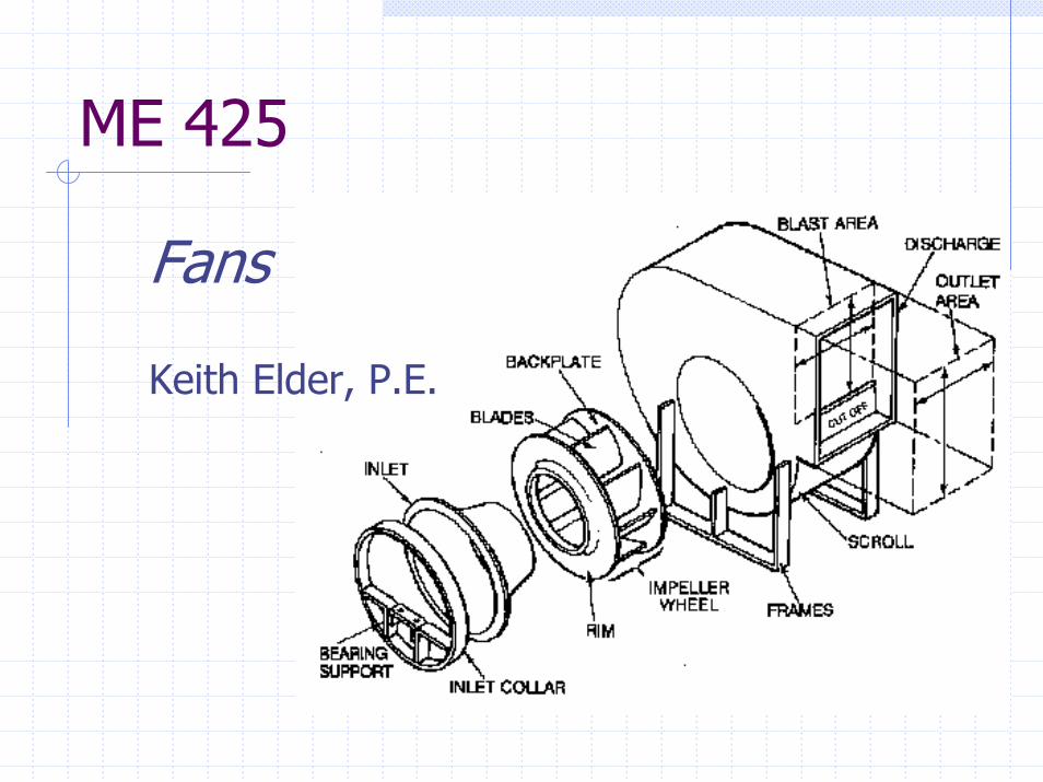
ME 425
Fans
Keith Elder, P.E.

Fan Types
Fans are classified by the direction of air flow relative to the impeller
Axial FansAir flow is perpendicular to blade rotation
Centrifugal FansAir flow is in the same direction as impeller rotation

Axial FansPropeller
Designed to move air from one enclosed space to another in a wide range of volumes at low pressures.
Tube-axialAn axial flow wheel in a cylinder which moves a wide range of air at medium pressures.
Vane-axialVane-axial fans have a set of air guide vanes mounted in the cylinder before or behind an airfoil-type wheel. They move air over a wide range of volumes and pressures.

Axial Fan Characteristics

Centrifugal FansDesigned to move air over a wide volume range. Static pressures can go up to 25 inches. Centrifugal fan wheels come in the following types:
AirfoilBackward InclinedRadialForward Curved

Centrifugal Fan Characteristics

Fan Horsepower
fan6359 ηxCFMxTPBHP =
6359CFMxTPAHP =
Where:ηfan= Fan EfficiencyAHP = Air HorsepowerBHP = Brake HorsepowerTP = Total Pressure, inches H2O

Fan Laws
Fan Performance at different speeds from the manufacturer’s fan curve can be predicted using the fan laws.
C F MC F M
R P MR P M
e s s u r ee s s u r e
R P MR P M
B H PB H P
R P MR P M
2
1
2
1
2
1
2
1
2
2
1
2
1
3
=
=
=
P rP r

Fan Law Problem
A fan has the following characteristics:5000 CFM1.25 inches static pressure782 RPM1.98 BHP
What RPM is necessary to increase the flow to 6,000 CFM?
What BHP is required?

System Curve
Pressure(in. w.c.)
CFM
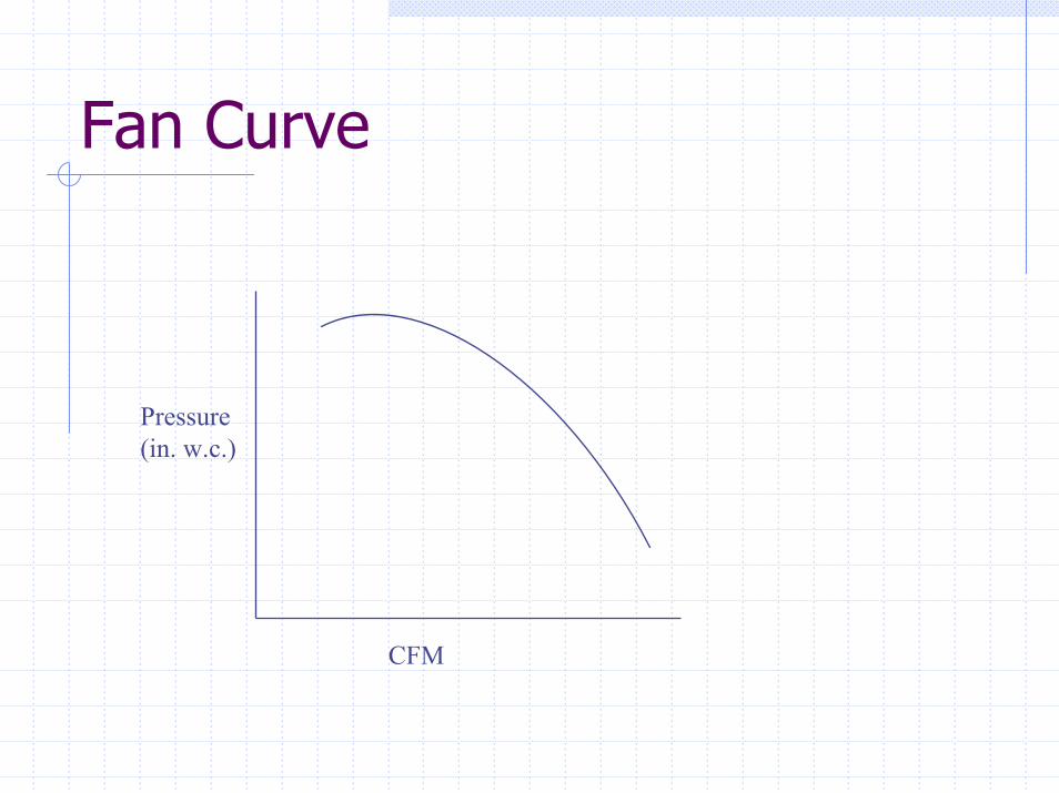
Fan Curve
Pressure(in. w.c.)
CFM
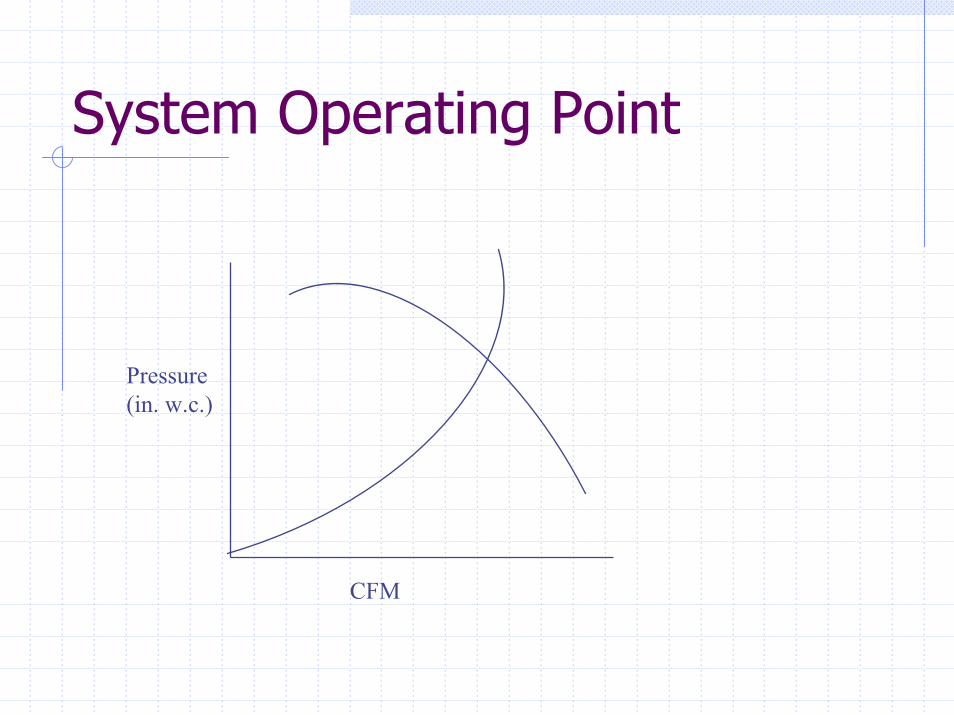
System Operating Point
Pressure(in. w.c.)
CFM

Catalog Fan Curve

Method of Obtaining Fan Curves
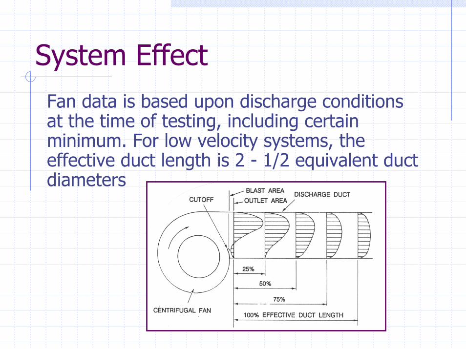
System EffectFan data is based upon discharge conditions at the time of testing, including certain minimum. For low velocity systems, the effective duct length is 2 - 1/2 equivalent duct diameters
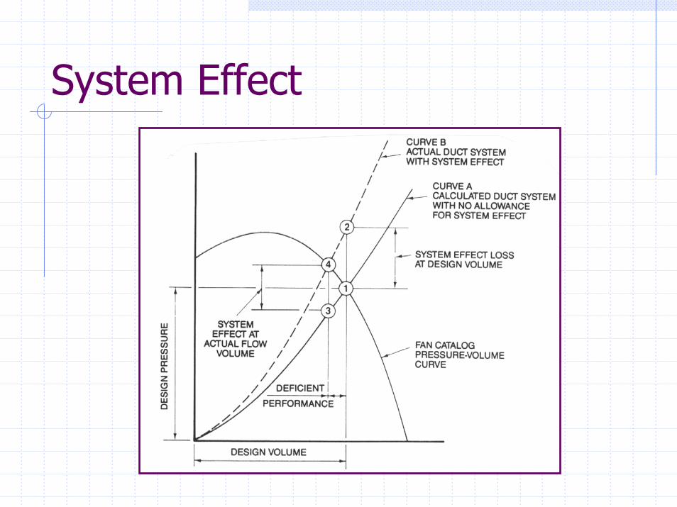
System Effect
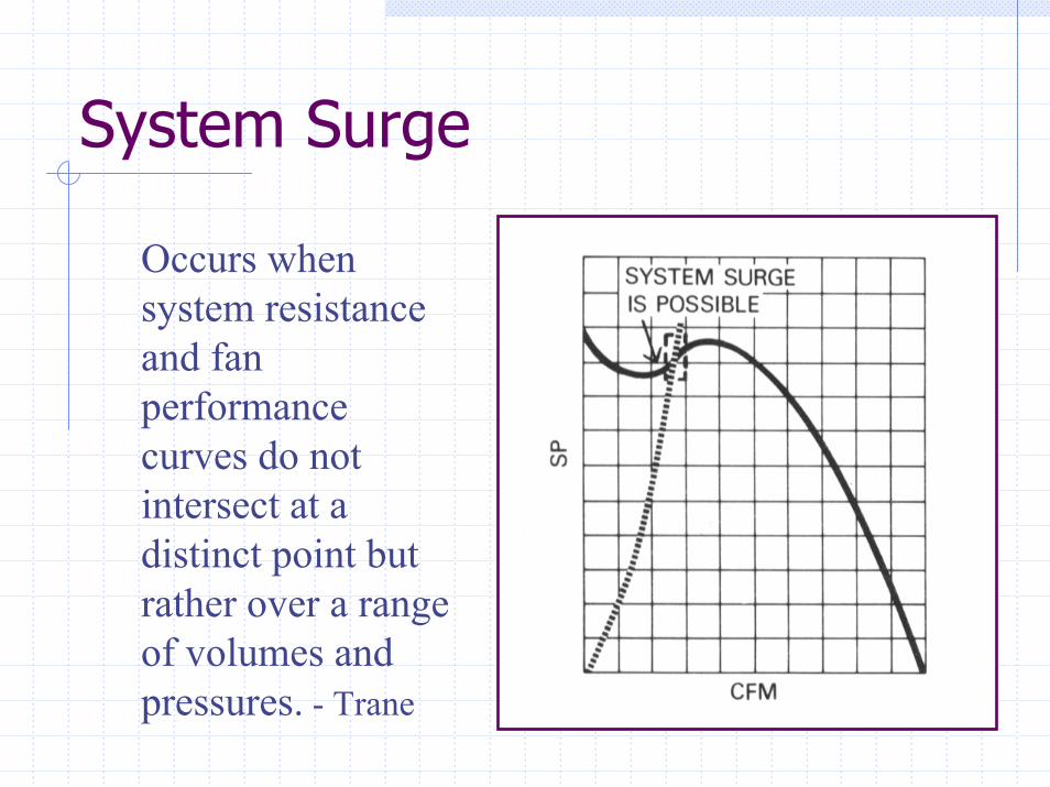
System Surge
Occurs when system resistance and fan performance curves do not intersect at a distinct point but rather over a range of volumes and pressures. - Trane

Fan Surge
Occurs near “block-tight” conditions when blade rotation is insufficient to overcome pressure difference between wheel center & discharge.
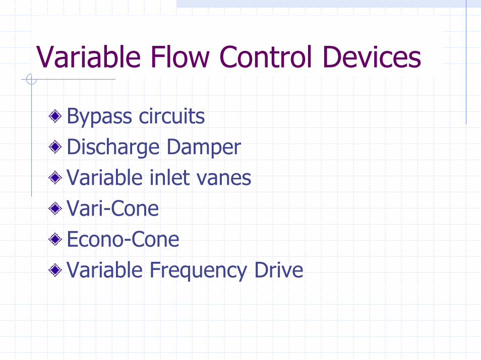
Variable Flow Control Devices
Bypass circuitsDischarge DamperVariable inlet vanesVari-ConeEcono-ConeVariable Frequency Drive
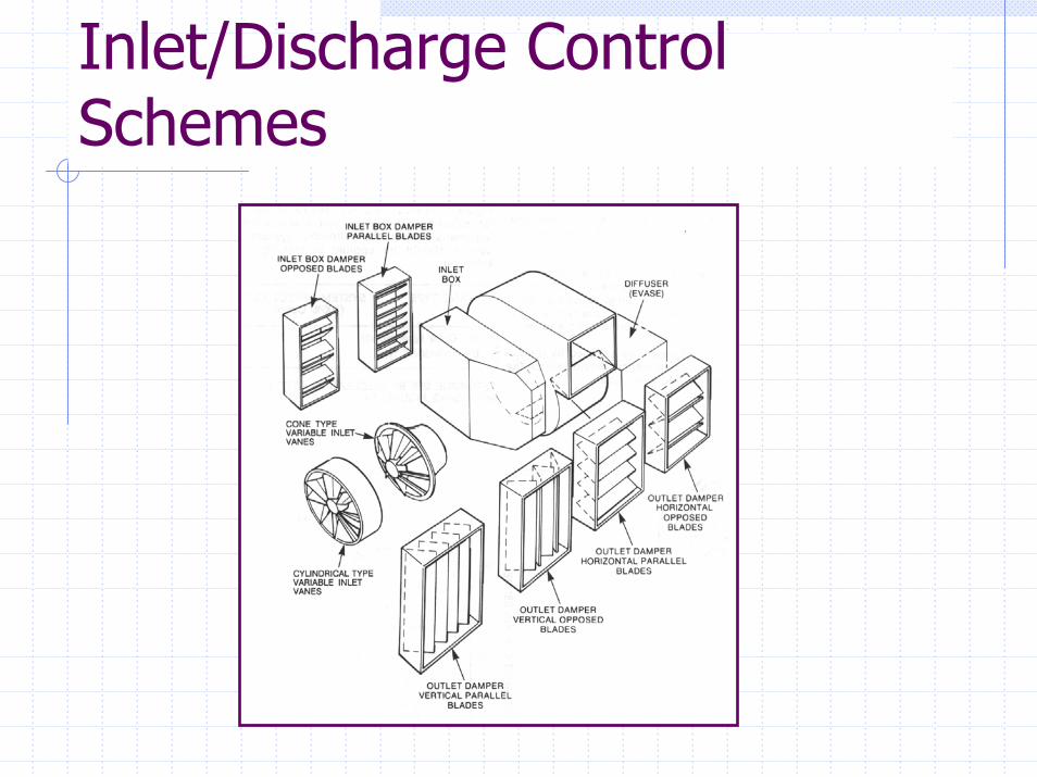
Inlet/Discharge Control Schemes

VAV Control Performance
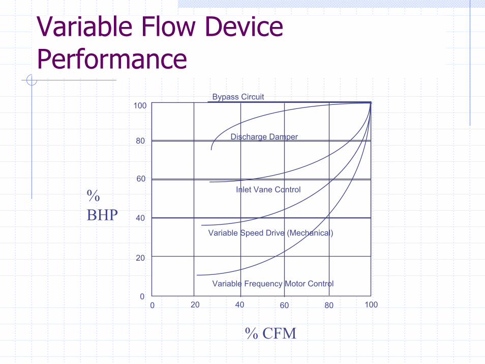
Variable Flow Device Performance
100
80
60
40
20
00 20 40 60 80 100
Variable Frequency Motor Control
Variable Speed Drive (Mechanical)
Inlet Vane Control
Discharge Damper
Bypass Circuit
%BHP
% CFM
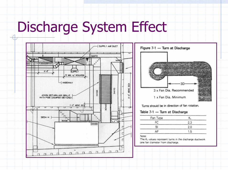
Discharge System Effect