4/2 and 4/3 directional valves, internally pilot-operated ......hydraulics bosch rexroth ag pilot...
TRANSCRIPT

InhaltTable of contents 1Features 1Ordering code 2Ordering code 3Symbols 4Symbols: Valve with 2 spool positions 5Symbols: Valve with 2 spool positions 6Symbols: Valves with 3 spool positions 7Function, section 8Pilot oil supply 9Technical data 9Technical data 10Technical data 11Technical data 12Electrical connection 13Electrical connection 14Characteristic curves: Type H-4WEH 10… (measured with HLP46, ϑoil = 40 °C ± 5 °C) 15Performance limits: Type H-4WEH 10… (measured with HLP46, ϑoil = 40 °C ± 5 °C) 15Characteristic curves: Type H-4WEH 16… (measured with HLP46, ϑoil = 40 °C ± 5 °C) 16Performance limits: Type H-4WEH 16… (measured with HLP46, ϑoil = 40 °C ± 5 °C) 16Characteristic curves: Type H-4WEH 25… (measured with HLP46, ϑoil = 40 °C ± 5 °C) 17Performance limits: Type H-4WEH 25… (measured with HLP46, ϑoil = 40 °C ± 5 °C) 17Characteristic curves: Type H-4WEH 32… (measured with HLP46, ϑoil = 40 °C ± 5 °C) 18Performance limits: Type H-4WEH 32… (measured with HLP46, ϑoil = 40 °C ± 5 °C) 18Performance limits: important notices 19Switching time adjustment, pressure reducing valve, preload valve 20Dimensions: Type H-4WEH 10… (dimensions in mm) 21Dimensions: Type H-4WEH 16… (dimensions in mm) 22Dimensions: Type H-4WEH 25… (dimensions in mm) 23Dimensions: Type H-4WEH 32… (dimensions in mm) 24Dimensions 25Further information 26Notes 27Notes 28
1/26
4/2 and 4/3 directional valves, internally pilot-operated, externally pilot-operated
Type H-4WEH …XE
Sizes 10, 16, 25, 32Component series 4X, 6X, 7XMaximum operating pressure 350 barMaximum flow 1100 l/min
RE 24751-XE/04.16Replaces: 09.13
H8097
ATEX units – For potentially explosive atmospheresInformation on explosion protection:
▶ Area of application in accordance with the Explosion Protection Directive 2014/34/EU: II 2G ▶ Type of protection of the valve solenoids: Ex eb mb IIC T4 Gb according to EN 60079-7 / EN 60079-18
Table of contents Features
Contents PageFeatures 1Ordering code 2, 3Symbols 4 … 7Function, section 8Pilot oil supply 9Technical data 9 … 12Electrical connection 13, 14Characteristic curves 15Performance limits 15 … 19Switching time adjustment, pressure reducing valve, preload valve 20Dimensions 21 … 25Further information 26
– For intended use in potentially explosive atmosphere– For subplate mounting– Porting pattern according to ISO 4401– Spring centering, spring end position or hydraulic
end position– Wet-pin DC or AC solenoids– Solenoid coil rotatable by 90° – Manual override, optional– Electrical connection as individual connection with cable
gland– Switching time adjustment, optional– Preload valve in channel P of the main valve, optional

2/26 Bosch Rexroth AG Hydraulics H-4WEH…XE... RE 24751-XE
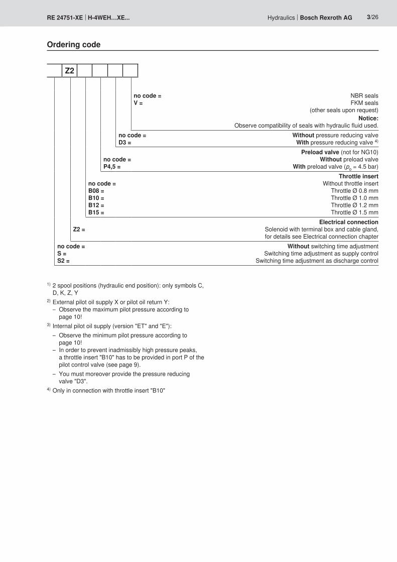
Ordering code
Up to 350 bar = H4-way version = 4Directional valve, electro-hydraulically actuated = WEHSizeNG10 = 10 NG16 = 16 NG25 = 25 NG32 = 32Control spool return main valveBy means of springs = no code Hydraulically 1) = HFor symbols, see page 4Component series 40 to 49 – NG10 = 4X (40 to 49: unchanged installation and connection dimensions)Component series 60 to 69 – NG25 (4W.H 25.) and NG32 = 6X (60 to 69: unchanged installation and connection dimensions)Component series 70 to 79 – NG16 = 7X (70 to 79: unchanged installation and connection dimensions)Control spool return in the pilot control valve with 2 spool positions and 2 solenoids only possible with control spool C, D, K, Z and hydraulic control spool return in the main valve:Without spring return = OWithout spring return with detent = OFPilot control valve with wet-pin solenoids, high-power valve (RE 23178-XE) = 6E Direct voltage 24 V = G24 AC voltage 230 V 50/60 Hz = W230R For further ordering codes for other voltages, see page 14Without manual override = no code With manual override (standard) = N Explosion protection "Increased safety" = XE For details see information on explosion protection, page 11Pilot oil supply external, pilot oil return external 2) = no code Pilot oil supply internal, pilot oil return external 3) = E Pilot oil supply internal, pilot oil return internal 3) = ET Pilot oil supply external, pilot oil return internal 2) = T
H 4 WEH 6E XE
Explanation of the footnotes, see page 3
Notice:The manual override cannot be allocated a safety function and may only be used up to a tank pressure of 50 bar.
Hydraulics Bosch Rexroth AGRE 24751-XE H-4WEH…XE... 3/26
Z2
no code = NBR seals V = FKM seals
(other seals upon request)Notice:
Observe compatibility of seals with hydraulic fluid used.no code = Without pressure reducing valve D3 = With pressure reducing valve 4)
Preload valve (not for NG10) no code = Without preload valve P4,5 = With preload valve (po = 4.5 bar)
Throttle insert no code = Without throttle insert B08 = Throttle Ø 0.8 mm B10 = Throttle Ø 1.0 mm B12 = Throttle Ø 1.2 mm B15 = Throttle Ø 1.5 mm
Electrical connection Z2 = Solenoid with terminal box and cable gland,
for details see Electrical connection chapter no code = Without switching time adjustment S = Switching time adjustment as supply control S2 = Switching time adjustment as discharge control
Ordering code
1) 2 spool positions (hydraulic end position): only symbols C, D, K, Z, Y
2) External pilot oil supply X or pilot oil return Y: – Observe the maximum pilot pressure according to
page 10!3) Internal pilot oil supply (version "ET" and "E"): – Observe the minimum pilot pressure according to
page 10! – In order to prevent inadmissibly high pressure peaks,
a throttle insert "B10" has to be provided in port P of the pilot control valve (see page 9).
– You must moreover provide the pressure reducing valve "D3".
4) Only in connection with throttle insert "B10"

A B
P TA B
P T
../..
..H../..
..H../O
..H../OF
= C
= D
= K
= Z
.A1)
.B
= E1)
= E192)
= G
= F
= J
= M
= P
= T
= S2)
= U
= V
= Q
= W
= H
= L
= R
aa b
aa b
A B
P Taa b
A B
P Ta
b
b
b
b
a b
a b
a b
A B
P Ta b ../..
= Y
A B
P Ta b ..H../..
A B
P Ta b
A B
P Ta
0
0a
a b
A B
P T0 bb
4/26 Bosch Rexroth AG Hydraulics H-4WEH…XE... RE 24751-XE
Symbols
2 spool positions 3 spool positions
1) Example: Symbol E with switching position "a" Order example:
H-4WEH 16 EA7X/6EG24N9XDETSZ2B10..V...
2) Only for NG16
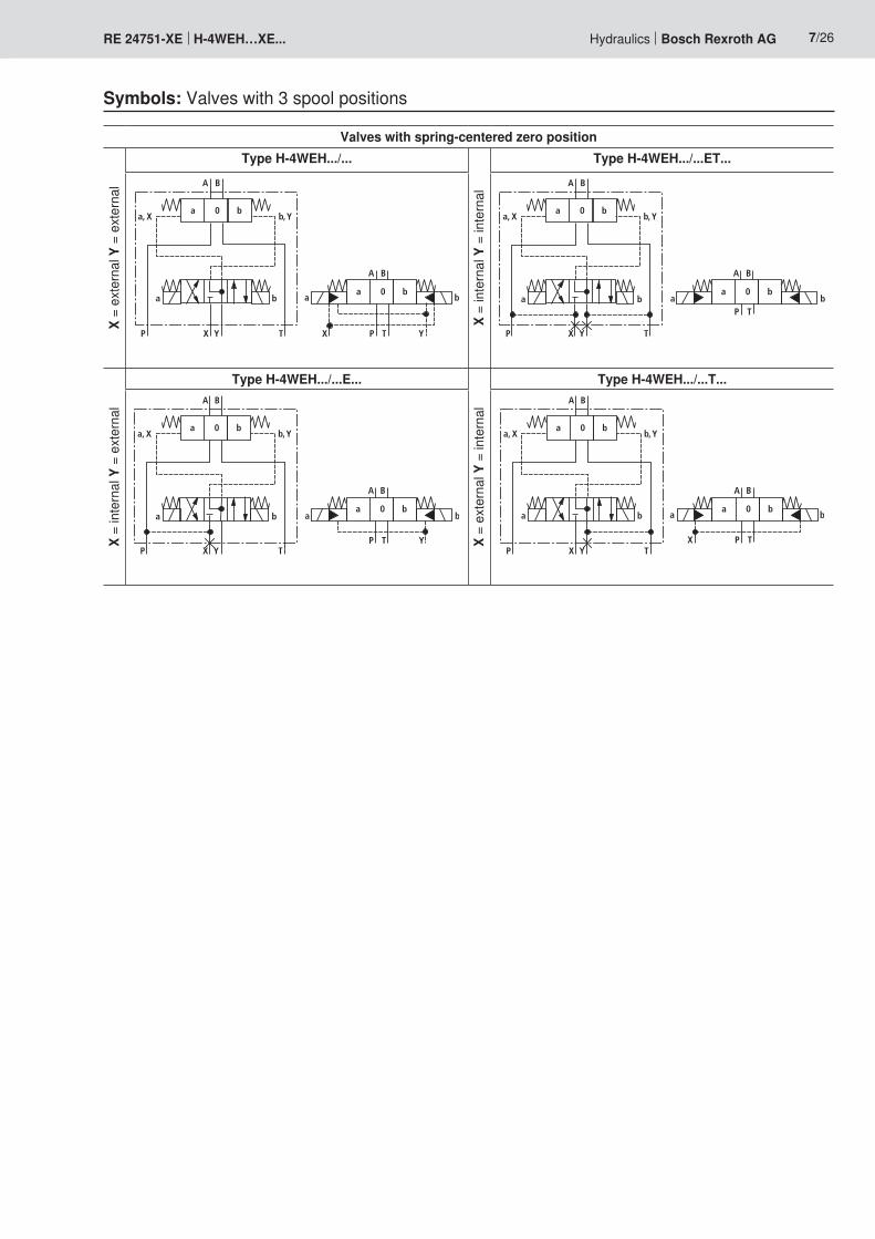
Notices:– Representation of the symbols according to DIN ISO 1219-1.
Hydraulic interim positions are represented by dashes.– Other symbols upon request

Hydraulics Bosch Rexroth AGRE 24751-XE H-4WEH…XE... 5/26
Symbols: Valve with 2 spool positions
Valves with spring end position Valves with hydraulic end position
X =
exte
rnal
Y =
ext
erna
l
Type H-4WEH.../... Type H-4WEH..H.../... Type H-4WEH..H.../O... Type H-4WEH..H.../OF...
A B
a ba
a b
P X Y T
b
P T
A B
P T
a ba, X b, Y
YX
P T YX
A B
a ba b
P T
A B
P T
a ba, X b, Y
YX
a b
P T
YX
A B
a ba b
P T
a b
P T
P T
YX
YX
A B
P T
a ba, X b, Y
A B
a ba b
P T
A B
P T
a ba, X b, Y
YX
a b
P T
YX
X =
inte
rnal
Y =
ext
erna
l
Type H-4WEH.../...E... Type H-4WEH..H.../...E... Type H-4WEH..H.../O...E... Type H-4WEH..H.../OF...E...
A B
A B
P T
a ba, X b, Y
YX
a ba b
P T YP T
a b
P TA B
A B
P T
a ba, X b, Y
YX
a ba b
P T Y
a b
P TA B
A B
P T
a ba, X b, Y
YX
a ba b
YP T
a b
P TA B
A B
P T
a ba, X b, Y
YX
a ba b
YP T
a b
P T
Continuation, see next page

6/26 Bosch Rexroth AG Hydraulics H-4WEH…XE... RE 24751-XE
Symbols: Valve with 2 spool positions
Valves with spring end position Valves with hydraulic end position
X =
inte
rnal
Y =
inte
rnal
Type H-4WEH.../...ET... Type H-4WEH..H.../...ET... Type H-4WEH..H.../O...ET... Type H-4WEH..H.../OF...ET...
A B
A B
P T
a ba, X b, Y
YX
a ba b
P T
a b
P TA B
A B
P T
a ba, X b, Y
YX
a ba b
P T
a b
P TA B
A B
P T
a ba, X b, Y
YX
a ba b
P T
a b
P TA B
A B
P T
a ba, X b, Y
YX
a ba b
P T
a b
P T
X =
exte
rnal
Y =
inte
rnal
Type H-4WEH.../...T... Type H-4WEH..H.../...T... Type H-4WEH..H.../O...T... Type H-4WEH..H.../OF...T...A B
P T
a ba, X b, Y
YX
A B
a ba b
X P T
a b
P T
A B
P T
a ba, X b, Y
YX
A B
a ba b
X P T
a b
P T
A B
P T
a ba, X b, Y
YX
A B
a ba b
X P T
a b
P T
A B
P T
a ba, X b, Y
YXA B
a ba b
X P T
a b
P T
Continuation from previous page
Hydraulics Bosch Rexroth AGRE 24751-XE H-4WEH…XE... 7/26
Symbols: Valves with 3 spool positions
Valves with spring-centered zero position
X =
exte
rnal
Y =
ext
erna
l
Type H-4WEH.../...
X =
inte
rnal
Y =
inte
rnal
Type H-4WEH.../...ET...A B
a 0a, X b, Y
b
A B
a 0 b
P TP TX Y
a b a b
X Y
A B
a 0a, X b, Y
b
A B
a 0 b
P T
P TX Y
a b a b
X =
inte
rnal
Y =
ext
erna
l
Type H-4WEH.../...E...
X =
exte
rnal
Y =
inte
rnal
Type H-4WEH.../...T...A B
a 0a, X b, Y
b
A B
a 0 b
P T YP TX Y
a b a b
A B
a 0a, X b, Y
b
A B
a 0 b
P TXP TX Y
a b a b

5.2 10 4 5.1
9
T
„b“ „a“
7
6
3.1
12
3.2
8
AP
BX Y
8/26 Bosch Rexroth AG Hydraulics H-4WEH…XE... RE 24751-XE
Directional valves type H-4WEH…The valve type H-4WEH is a directional spool valve with electro-hydraulic actuation. It controls the start, stop and direction of a flow.The directional valve basically consists of the main valve with housing (1), the main control spool (2), one or two return springs (3.1) and (3.2), as well as the pilot control valve (4) with one or two solenoids "a" (5.1) and/or "b" (5.2).The main control spool (2) in the main valve is held in the zero or initial position by the springs or by means of pressurization. In the initial position, the two spring chambers (6) and (8) are connected with the tank in a depressurized form via the pilot control valve (4). The pilot control valve is supplied with pilot oil via the control line (7). Supply can be effected internally or externally (externally via port X).Upon actuation of the pilot control valve, e. g. solenoid "a", the pilot control spool (10) is moved to the left and thus, the spring chamber (8) is pressurized with pilot pressure. The spring chamber (6) remains depressurized.
The pilot pressure acts on the left side of the main control spool (2) and moves it against the spring (3.1). This connects ports P with B and A with T in the main valve.When the solenoid is switched off, the pilot control spool returns into the initial position (except for impulse spool). The spring chamber (8) is unloaded to the tank.The pilot oil from the spring chamber is displaced into channel Y via the pilot control valve.The pilot oil supply and return can be effected internally or externally.The manual override (9) allows control spool (10) to be moved without solenoid energization.Notices:The main control spool (2) is held in central position by the return springs (3.1) and (3.2) in spring chambers (6) and (8) without pilot pressure, even if the valve is positioned for example vertically.Due to the design principle, internal leakage is inherent to the valves, which may increase over the life cycle.
Function, section
Type H-4WEH 16…XE...

Hydraulics Bosch Rexroth AGRE 24751-XE H-4WEH…XE... 9/26
Type H-4WEH…The pilot oil supply is effected externally via the X channel from a separate circuit.The pilot oil return is effected externally via the Y channel into the tank.Type H-4WEH…E…The pilot oil supply is effected internally from the P channel of the main valve. The pilot oil return is effected externally via the Y channel into the tank. In the subplate, port X is closed.Type H-4WEH…ET…The pilot oil supply is effected internally from the P channel of the main valve.The pilot oil return is effected internally via the T channel into the tank. In the subplate, ports X and Y are closed.Type H-4WEH…T…The pilot oil supply is effected externally via the X channel from a separate circuit.The pilot oil return is effected internally via the T channel into the tank. In the subplate, port Y is closed.
Pilot oil supply
�
�
�
��
Throttle insertUse of the throttle insert (2) is necessary if the pilot oil supply in the P channel of the pilot control valve (1) is to be limited.The throttle insert (2) is inserted in channel P of the pilot control valve (1).
1 Pilot control valve2 Throttle insert3 Seal ring4 Main valve
Technical datageneralInstallation position Any; horizontal with valves with hydraulic control spool return
"H" and control spool C, D, K, Z or YAmbient temperature range °C –20 … +70 1)
Storage temperature range °C +5 ... +40Maximum storage time Years 1Sizes NG 10 16 25 32Weight Valve with one solenoid kg 8.5 11 19 36.5
Valve with two solenoids, spring-centered kg 10.2 12.5 20.5 39Switching time adjustment kg 0.8Pressure reducing valve kg 0.4
Surface protection
Valve body Pilot control valve GalvanizedMain valve Galvanized
Solenoid GalvanizedMTTFd value according to EN ISO 13849 Years 100
1) Observe the "Special application conditions for safe application" on page 11.

10/26 Bosch Rexroth AG Hydraulics H-4WEH…XE... RE 24751-XE
Technical datahydraulicSizes NG 10 16 25 32Maximum operating pressure
Ports P, A, B bar 350Port T with pilot oil return
Y external bar 250
with pilot oil return Y internal bar 210
Port Y with pilot oil return external bar 210
Flow of the main valve l/min up to 160 up to 300 up to 650 up to 1100Maximum pilot pressure bar 250 (with a higher pilot pressure, use of a pressure reducing
valve is required)Minimum pilot pressure– with external or internal pilot oil supply X
(control spool D, K, E, J, L, M, Q, R, U, W)3-spool position valve, spring-centered bar 10 14 13 8.52-spool position valve, spring end position bar 10 14 13 102-spool position valve, hydraulic end position bar 7 14 8 5
– with internal pilot oil supply X (control spools C, F, H, P, T, V, Z, S 2) ) bar 6.5 3) 4.5 4) 4.5 4) 4.5 4)
Pilot volume for switching process3-spool position valve, spring-centered cm3 2.04 5.72 14.2 29.42-spool position valve cm3 4.08 11.45 28.4 58.8
Pilot volume for shortest switching time l/min approx. 35 approx. 35 approx. 35 approx. 45Hydraulic fluid See table belowHydraulic fluid temperature range °C –20 ... +80 (NBR seals)
–15 ... +80 (FKM seals)Viscosity range mm2/s 2.8 … 500 Maximum admissible degree of contamination of the hydraulic fluid Cleanliness class according to ISO 4406 (c)
Class 20/18/15 5)
Maximum surface temperature °C See information on explosion protection on page 11
Hydraulic fluid Classification Suitable sealing materials
Standards Data sheet
Mineral oils HL, HLP, HLPD NBR, FKM DIN 51524 90220Bio-degradable ▶ Insoluble in water HETG NBR, FKM ISO 15380 90221
HEES FKM ▶ Soluble in water HEPG FKM ISO 15380
Flame-resistant ▶ Containing water HFC (Fuchs Hydrotherm 46M, Petrofer Ultra Safe 620)
NBR ISO 12922 90223
Important information on hydraulic fluids: ▶ For further information and data on the use of other hydraulic fluids, please refer to the data sheets above or contact us!
▶ There may be limitations regarding the technical valve data (temperature, pressure range, life cycle, maintenance intervals, etc.)!
▶ Ignition temperature > 180 °C
▶ Flame-resistant – containing water: – Maximum pressure differential per control edge 50 bar – Pressure pre-loading at the tank port > 20% of the pressure differential, otherwise increased cavitation
– Life cycle as compared to operation with mineral oil HL, HLP 50 to 100%
Footnotes, see page 11
Hydraulics Bosch Rexroth AGRE 24751-XE H-4WEH…XE... 11/26
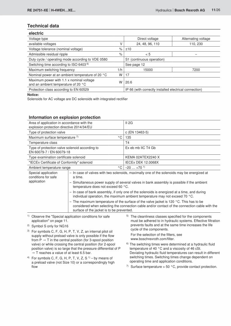
electricVoltage type Direct voltage Alternating voltageavailable voltages V 24, 48, 96, 110 110, 230Voltage tolerance (nominal voltage) % ±10Admissible residual ripple % < 5 –Duty cycle / operating mode according to VDE 0580 S1 (continuous operation)Switching time according to ISO 6403 6) See page 12Maximum switching frequency 1/h 15000 7200Nominal power at an ambient temperature of 20 °C W 17Maximum power with 1.1 x nominal voltage and an ambient temperature of 20 °C W 20.6
Protection class according to EN 60529 IP 66 (with correctly installed electrical connection)
Technical data
Information on explosion protectionArea of application in accordance with the explosion protection directive 2014/34/EU
II 2G
Type of protection valve c (EN 13463-5)Maximum surface temperature 7) °C 135Temperature class T4Type of protection valve solenoid according to EN 60079-7 / EN 60079-18
Ex eb mb IIC T4 Gb
Type examination certificate solenoid KEMA 02ATEX2240 X"IECEx Certificate of Conformity" solenoid IECEx DEK 12.0068XAmbient temperature range °C –20 … +70 1)
Special application conditions for safe application
– In case of valves with two solenoids, maximally one of the solenoids may be energized at a time.
– Simultaneous power supply of several valves in bank assembly is possible if the ambient temperature does not exceed 60 °C.
– In case of bank assembly, if only one of the solenoids is energized at a time, and during individual operation, the maximum ambient temperature may not exceed 70 °C.
– The maximum temperature of the surface of the valve jacket is 120 °C. This has to be considered when selecting the connection cable and/or contact of the connection cable with the surface of the jacket is to be prevented.
1) Observe the "Special application conditions for safe application" on page 11.
2) Symbol S only for NG163) For symbols C, F, G, H, P, T, V, Z, an internal pilot oil
supply without preload valve is only possible if the flow from P → T in the central position (for 3-spool position valve) or while crossing the central position (for 2-spool position valve) is so large that the pressure differential of P → T reaches a value of at least 6.5 bar.
4) For symbols C, F, G, H, P, T, V, Z, S 1) – by means of a preload valve (not Size 10) or a correspondingly high flow
5) The cleanliness classes specified for the components must be adhered to in hydraulic systems. Effective filtration prevents faults and at the same time increases the life cycle of the components.
For the selection of the filters, see www.boschrexroth.com/filter.
6) The switching times were determined at a hydraulic fluid temperature of 40 °C and a viscosity of 46 cSt. Deviating hydraulic fluid temperatures can result in different switching times. Switching times change dependent on operating time and application conditions.
7) Surface temperature > 50 °C, provide contact protection.
Notice: Solenoids for AC voltage are DC solenoids with integrated rectifier

12/26 Bosch Rexroth AG Hydraulics H-4WEH…XE... RE 24751-XE
Technical data
Free flow cross-sections in zero position with control spools Q, V and WControl spool Q A – T, B – T mm2 13 32 78 83 78Control spool V A – T, B – T mm2 13 32 73 83 73
P – A, P – B mm2 13 32 84 83 84Control spool W A – T, B – T mm2 2.4 6 10 14 20
Switching times (= Contacting at the pilot control valve until start of opening of the control edge in the main valve and change in the control spool stroke by 95%)
Pilot pressure bar 70 250 SpringON OFF
NG10 without throttle insert ms 50 ... 70 50 ... 70 30 ... 40with throttle insert ms 70 ... 100 60 ... 80 30 ... 40
NG16 without throttle insert ms 60 ... 90 50 ... 70 60 ... 90with throttle insert ms 120 ... 140 90 ... 110 60 ... 90
NG25 without throttle insert ms 80 ... 110 60 ... 80 110 ... 140with throttle insert ms 210 ... 260 130 ... 160 110 ... 140
NG32 without throttle insert ms 90 ... 140 80 ... 110 150 ... 170with throttle insert ms 430 ... 570 240 ... 360 150 ... 170
Notices:– The switching times are measured according to ISO 6403
with HLP46, ϑoil = 40 °C ± 5 °C. With different oil temperatures, variations are possible.
– The switching times increase by approx. 30 ms if the pressure reducing valve "D3" is used.
– The switching times have been determined under ideal conditions and may differ in the system, depending on the application conditions.

1 2
3
Hydraulics Bosch Rexroth AGRE 24751-XE H-4WEH…XE... 13/26
Electrical connectionThe type-examination tested valve solenoid of the valve is equipped with a terminal box and a type-tested cable gland.
NoticeWhen establishing the electrical connection, the protective earthing conductor (PE ) has to be connected properly.
Connection lineLine type Non-armored cables and lines (outer sheath sealing)Temperature range °C –30 … > +110
The connection is polarity-independent.Solenoids to be connected to AC voltage are equipped with an integrated rectifier.
Properties of the connection terminalsPosition Function Connectable line cross-section
1 Operating voltage connection Single-wire 0.75 … 2.5 mm2
Finely stranded 0.75 … 1.5 mm2
2 Connection for protective earthing conductor Single-wire max. 2.5 mm2
Finely stranded max. 1.5 mm2
3 Connection for potential equalization conductor Single-wire 4 … 6 mm2
Finely stranded 4 mm2
Cable glandType approval II 2G Ex e IIC GbThreaded connection M20 x 1.5Protection class according to EN 60529 IP 66 (with correctly installed electrical connection)Line diameter mm 7 … 10.5Sealing Outer sheath sealing

14/26 Bosch Rexroth AG Hydraulics H-4WEH…XE... RE 24751-XE
Electrical connection
Circuit diagrams
Direct voltage, polarity-independent Alternating voltage
����
�����
Over-current fuse and switch-off voltage peak
Voltage data in the valve type code
Nominal voltage valve
solenoid
Rated current valve
solenoid
Rated current for external miniature fuse: medium time-lag (M) according to DIN 41571 and
EN/IEC 60127
Rated voltage for external miniature fuse: medium time-lag (M) according to DIN 41571 and
EN/IEC 60127
Maximum voltage
value upon switch-off
Interference protection
circuit
G24 24 V DC 0.708 A DC 800 mA 250 V –90 V
Suppressor diode
bi-directional
G48 48 V DC 0.354 A DC 400 mA 250 V –200 V
G96 96 V DC 0.177 A DC 200 mA 250 V –370 V
G110 110 V DC 0.155 A DC 200 mA 250 V –390 V
W110R 110 V AC 0.163 A AC 200 mA 250 V –3 V Bridge rectifier and suppressor
diodeW230R 230 V AC 0.078 A AC 80 mA 250 V –3 V
Notice:A fuse which corresponds to the rated current according to DIN 41571 and EN / IEC 60127 has to be connected upstream of every valve solenoid (max. 3 x Irated).The shut-off threshold of the fuse has to match the prospective short-circuit current of the supply source.The prospective short-circuit current of the supply source may amount to a maximum of 1500 A.
This fuse may only be installed outside the potentially explosive atmosphere or must be of an explosion-proof design.When inductivities are switched off, voltage peaks result which may cause faults in the connected control electronics.The voltage peak must be damped by a suitable external circuitry. We recommend a circuitry with a suppressor diode with a limitation voltage of approx. 50 V.

6
1
10
8
6
4
2
20 40 60 80 100 120 140 16000
12
14
22
16
18
20
2
7
43
5
Hydraulics Bosch Rexroth AGRE 24751-XE H-4WEH…XE... 15/26
Characteristic curves: Type H-4WEH 10… (measured with HLP46, ϑoil = 40 °C ± 5 °C)
Symbol Spool position Symbol Zero positionP – A P – B A – T B – T A – T B – T P – T
E, Y, D 2 2 4 5F 1 4 1 4 F 3 – 6G, T 4 2 2 6 G, T – – 7H, C 4 4 1 4 H 1 3 5J, K 1 2 1 3L 2 3 1 4 L 3 – –M 4 4 3 4P 4 1 3 4 P – 7 5Q, V, W, Z 2 2 3 5R 2 2 3 –U 3 3 3 4 U – 4 –
Performance limits: Type H-4WEH 10… (measured with HLP46, ϑoil = 40 °C ± 5 °C)2- and 3-spool position valves maximum flow qV in l/minSymbol Operating pressure pmax in bar
200 250 315E, J, L, M, Q, R, U, V, W, C, D, K, Z, Y
160 160 160
H 160 150 120G, T 160 160 140F, P 160 140 120
Important notices see page 19.
∆p - qV characteristic curves
Flow in l/min →
Pres
sure
diff
eren
tial in
bar
→

02468
10121416182022242628
0 50 100 150 200 250 300
87654321
10
9
16/26 Bosch Rexroth AG Hydraulics H-4WEH…XE... RE 24751-XE
Characteristic curves: Type H-4WEH 16… (measured with HLP46, ϑoil = 40 °C ± 5 °C)
Symbol Spool positionP – A P – B A – T B – T P – T
E, Y, D 1 1 3 4 –E19 – 6 8 7 –F 1 1 5 4 –G, T 4 1 5 5 9H, C, Q, V, Z 1 1 5 6 –J, K, L 1 1 5 6 –
Symbol Spool positionP – A P – B A – T B – T P – T
M, W 1 1 3 4 –R 1 1 3 – –U 2 2 3 5 –S 3 3 3 – 10
Performance limits: Type H-4WEH 16… (measured with HLP46, ϑoil = 40 °C ± 5 °C)
∆p - qV characteristic curves
Flow in l/min →
Pres
sure
diff
eren
tial in
bar
→
2-spool position valve maximum flows qV in l/minSymbol Operating pressure pmax in bar
70 140 210 280 350X external, spring end position in the main valve (with pSt min =12 bar)C, D, K, Y, Z 300 300 300 300 300X external, spring end position in the main valve 1)
C 300 300 300 300 300D, Y 300 270 260 250 230K 300 250 240 230 210Z 300 260 190 180 160X external, hydraulic end position in the main valveHC, HD, HK, HZ, HY 300 300 300 300 300
3-spool position valve maximum flows qV in l/minControl spool Operating pressure pmax in bar
70 140 210 280 350X external, spring centering in the main valve E, E19, H, J, L, M, Q, U, W, R 300 300 300 300 300
F, P 300 250 180 170 150G, T 300 300 240 210 190S 300 300 300 250 220V 300 250 210 200 180
1) If the specified flow values are exceeded, the function of the return spring is no longer guaranteed if the pilot pressure fails!
• With control spools V, Z and HZ, the preload valve is not required for flows > 180 l/min.
Important notices see page 19.

1
234
5
6
0 100 200 300 400 500
78
600 650
10
8
6
4
2
12
1416
1820
22
Hydraulics Bosch Rexroth AGRE 24751-XE H-4WEH…XE... 17/26
Characteristic curves: Type H-4WEH 25… (measured with HLP46, ϑoil = 40 °C ± 5 °C)
Performance limits: Type H-4WEH 25… (measured with HLP46, ϑoil = 40 °C ± 5 °C)2-spool position valve maximum flows qV in l/minSymbol Operating pressure pmax in bar
70 140 210 280 350X external, spring end position in the main valve (with pSt min =13 bar)C, D, K, Y, Z 700 700 700 700 650X external, spring end position in the main valve 1)
C 700 700 700 700 650D, Y 700 650 400 350 300K 700 650 420 370 320Z 700 700 650 480 400X external, hydraulic end position in the main valveHC, HD, HK, HZ, HY 700 700 700 700 700
HC../O.. HD../O.. HK../O.. HZ../O..
700 700 700 700 700
HC../OF.. HD../OF.. HK../OF.. HZ../OF..
700 700 700 700 700
3-spool position valve maximum flows qV in l/minSymbol Operating pressure pmax in bar
70 140 210 280 350X external, spring centering in the main valve E, L, M, Q, U, W, 700 700 700 700 650
G, T 400 400 400 400 400F 650 550 430 330 300H 700 650 550 400 360J 700 700 650 600 520P 650 550 430 330 300V 650 550 400 350 310R 700 700 700 650 580
Characteristic curve selectionSymbol Spool position
P – A P – B A – T B – TE 1 1 1 3F 1 4 3 3G 3 1 2 4H 4 4 3 4J, Q 2 2 3 5
Symbol Spool positionP – A P – B A – T B – T
U 4 1 1 6V 2 4 3 6W 1 1 1 3T 3 1 2 4
Symbol Spool positionP – A P – B A – T B – T
L 2 2 3 3M 4 4 1 4P 4 1 1 5R 2 1 1 –
∆p - qV characteristic curves
Flow in l/min →
Pres
sure
diff
eren
tial in
bar
→
7 Symbol G central position P – T
8 Symbol T central position P – T
B -A symbol R
1) If the specified flow values are exceeded, the function of the return spring is no longer guaranteed if the pilot pressure fails!
Important notices see page 19.

18/26 Bosch Rexroth AG Hydraulics H-4WEH…XE... RE 24751-XE
Characteristic curves: Type H-4WEH 32… (measured with HLP46, ϑoil = 40 °C ± 5 °C)
Performance limits: Type H-4WEH 32… (measured with HLP46, ϑoil = 40 °C ± 5 °C)
��
��
��
�
�
�
�
�� ��� ��� ��� ������ ���
��
��
��� ��� ����
�
�
�
�
Flow in l/min →
Pres
sure
diff
eren
tial in
bar
→
∆p - qV characteristic curves – Symbol G and T
2-spool position valve maximum flows qV in l/minSymbol Operating pressure pmax in bar
70 140 210 280 350X external, spring end position in the main valve (with pSt min =10 bar)C, D, K, Y, Z 1100 1040 860 750 680X external, spring end position in the main valve 1)
C 1100 1040 860 800 700D, Y 1100 1040 540 480 420K 1100 1040 860 500 450Z 1100 1040 860 700 650X external, hydraulic end position in the main valveHC, HD, HK, HZ, HY 1100 1040 860 750 680
3-spool position valve maximum flows qV in l/minSymbol Operating pressure pmax in bar
70 140 210 280 350X external, spring centering in the main valve E, J, L, M, Q, U, W, R 1100 1040 860 750 680
G, T, H, F, P 900 900 800 650 450V 1100 1000 680 500 450
∆p - qV characteristic curves – Symbol E, R and W
Flow in l/min →
Pres
sure
diff
eren
tial in
bar
→
��
��
��
�
�
�
�
�� ��� ��� ��� ������ ���
��
��
��� ��� ����
�
�
�
�
Symbol Spool positionP – A P – B A – T B – T B – A
E 4 4 3 2 –R 4 4 3 – 1W 4 4 3 2 –
Symbol Spool positionP – A P – B A – T B – T P – T
G 7 8 7 5 6T 7 8 7 5 6
1) If the specified flow values are exceeded, the function of the return spring is no longer guaranteed if the pilot pressure fails!
Important notices see page 19.

Hydraulics Bosch Rexroth AGRE 24751-XE H-4WEH…XE... 19/26
Performance limits: important notices
NG16 – With pilot oil supply X internal, a preload valve has to be used for flows < 160 l/min due to the negative overlap of symbols V, C, Z and HC, HZ.
– With pilot oil supply X internal, sufficient flow has to be ensured due to the negative overlap of symbols F, G, H, P, S and T (for the determination of the required flow, see "Preload valve" characteristic curves (page 20). If the required flow is not reached, a preload valve has to be used (see page 10).
NG25 – With pilot oil supply X internal, a preload valve has to be used for flows < 180 l/min due to the negative overlap of the symbols Z, HZ and V.
– With pilot oil supply X internal, sufficient flow has to be ensured due to the negative overlap of symbols C, HC, F, G, H, P, and T (for the determination of the required flow, see "Preload valve" characteristic curves (page 20). If the required flow is not reached, a preload valve has to be used (see page 10).
NG32 – With pilot oil supply X internal, a preload valve has to be used for flows < 180 l/min due to the negative overlap of the symbols Z, HZ and V.
– With pilot oil supply X internal, sufficient flow has to be ensured due to the negative overlap of symbols C, HC, F, G, H, P, and T (for the determination of the required flow, see "Preload valve" characteristic curves (page 20). If the required flow is not reached, a preload valve has to be used (see page 10).
Notice (applies to all sizes):The specified switching power limits are valid for use with two directions of flow (e. g. from P to A and simultaneous return flow from B to T at a ratio of 1:1).Due to the flow forces acting within the valves, the admissible switching power limit may be considerably lower with only one direction of flow (e. g. from P to A while port B
is blocked, with flow in the same or different directions)!In such cases, please consult us!The switching power limit was established while the solenoids were at operating temperature, at 10% undervoltage and without tank preloading.

��
1
2
5
Hydraulics Bosch Rexroth AGRE 24751-XE H-4WEH…XE... 20/26
Switching time adjustment, pressure reducing valve, preload valve
Switching time adjustment "S/S2"The switching time of the main valve (1) is influenced by using a twin throttle check valve (2), type Z2FS 6.Symbol (3) shows the switching time adjustment "S" (supply control), symbol (4) shows the switching time adjustment "S2" (discharge control)
Type H-4WEH 10 ..4X/…S or S2
Pressure reducing valve "D3"With the design internal pilot oil supply (ET or E) or external pilot oil supply and a pilot pressure of more than 250 bar, the valve must be ordered with a pressure reducing valve (5), type ZDR6PO, and a throttle insert "B10".Ordering code: "B10..D3"
Type H-4WEH 10 ..4X/…/..D3
Preload valve "P4,5" (not for NG10)In case of valves with depressurized circulation and internal pilot oil supply, a preload valve is required in channel P of the main valve in order to build up the minimum pilot pressure.Ordering code: "P4,5"The pressure differential of the preload valve is to be added to the pressure differential of the main valve (see characteristic curves) to result in one total value.The cracking pressure amounts to approx. 4.5 bar.
Pres
sure
diff
eren
tial in
bar
→
Flow in l/min →
∆p–qV characteristic curve (measured with HLP46, ϑOil = 40 °C ± 5 °C)
141210
8
6
4
2
00 100 200 300 400 500 600 700
12 3
1 = NG16 2 = NG25 3 = NG32

704523
AT B T
Y
AT B T
1
9
„b“ „a“
X
35
54Ø11Ø6,6
8721
4010
1
2.32.213
15
3.24
8
3.1
15
132.17
5
P
P
PABT
6
27
13,5
108
PA B
TY
T1
73
F1 F2
F4 F3
2
X
110,556,5
16
28880
Hydraulics Bosch Rexroth AGRE 24751-XE H-4WEH…XE... 21/26
Dimensions: Type H-4WEH 10… (dimensions in mm)
Rzmax 4
0,01/100
Subplates (separate order) with porting pattern according to ISO 4401-05-05-0-05, see data sheet 45100.
Notice:Subplates are no components in the sense of directive 2014/34/EU and can be used after the manufacturer of the overall system has conducted an assessment of the risk of ignition. The "G...J3" versions are free from aluminum and/or magnesium and galvanized.
Valve mounting screws (separate order)For reasons of stability, exclusively use the following valve mounting screws: 4 hexagon socket head cap screws ISO 4762 - M6x45-10.9-flZn-240h-L (friction coefficient µtotal = 0.09 to 0.14)
Item explanations see page 25.
Required surface quality of the valve contact surface

A B Y
2755 155
96 18
9
10
1211
63163
15555
4010
121
2.32.213
15
3.2
45
132.17
3.1
15
14
„b“ „a“
6
142
21
94
12
F1F2
PBA
XT
F3F4
Y
F5
F6G2
G1
2
43
1628880
34,1Ø11Ø6,6
Ø18Ø11
XP
B YA
50101,6
93
1,6
3569
,9
1,6
P
TB A
T
22/26 Bosch Rexroth AG Hydraulics H-4WEH…XE... RE 24751-XE
Dimensions: Type H-4WEH 16… (dimensions in mm)
Rzmax 4
0,01/100
Subplates (separate order) with porting pattern according to ISO 4401-07-07-0-05, see data sheet 45100.
Notice:Subplates are no components in the sense of directive 2014/34/EU and can be used after the manufacturer of the overall system has conducted an assessment of the risk of ignition. The "G...J3" versions are free from aluminum and/or magnesium and galvanized.
Valve mounting screws (separate order)For reasons of stability, exclusively use the following valve mounting screws: 4 hexagon socket head cap screws ISO 4762-M10x60-10.9-flZn-240h-L (friction coefficient total: 0.09-0.14 according to VDA 235-101)2 hexagon socket head cap screws ISO 4762-M6x60-10.9-flZn-240h-L (friction coefficient µtotal = 0.09 to 0.14)
Item explanations see page 25.
Required surface quality of the valve contact surface

AXB
T P Y92 11
7
13077
53Ø20Ø14
19225
252,5
225
126
18
9
10
1112
„b“ „a“
4010
121
2.172.32.213
153.2
4
5
15
3.1
13
14
P
TB A
7272
99,5
6
F1 F2
P
BAX
T
F3F4
Y
F5
F6G2
G7
195
120
21
14
2
41
28880
16
Hydraulics Bosch Rexroth AGRE 24751-XE H-4WEH…XE... 23/26
Dimensions: Type H-4WEH 25… (dimensions in mm)
Rzmax 4
0,01/100
Subplates (separate order) with porting pattern according to ISO 4401-08-08-0-05, see data sheet 45100.
Notice:Subplates are no components in the sense of directive 2014/34/EU and can be used after the manufacturer of the overall system has conducted an assessment of the risk of ignition. The "G...J3" versions are free from aluminum and/or magnesium and galvanized.
Valve mounting screws (separate order)For reasons of stability, exclusively use the following valve mounting screws: 6 hexagon socket head cap screws ISO 4762-M12x60-10.9-flZn-240h-L (friction coefficient µtotal = 0.09 to 0.14)
Item explanations see page 25.
Required surface quality of the valve contact surface

76
T
Ø19Ø33Ø22
P Y
X A B
114,5190,5
159
79,5
197
286,521,5
152
8
9
10
11
12
1
„b“ „a“
101
2140
2.172.32.2
3.1
5
13
15
4
13
153.2
P
TB A
286,575,5
286,5104,575,5 315,5
14 6
F1 F2
P
BAX
T
F3F4
Y
F5
F6G2
G1
257
23
200
20,5
2
49
16
28880
24/26 Bosch Rexroth AG Hydraulics H-4WEH…XE... RE 24751-XE
Dimensions: Type H-4WEH 32… (dimensions in mm)
Rzmax 4
0,01/100
Subplates (separate order) with porting pattern according to ISO 4401-10-09-0-05, see data sheet 45100.
Notice:Subplates are no components in the sense of directive 2014/34/EU and can be used after the manufacturer of the overall system has conducted an assessment of the risk of ignition. The "G...J3" versions are free from aluminum and/or magnesium and galvanized.
Valve mounting screws (separate order)For reasons of stability, exclusively use the following valve mounting screws: 6 hexagon socket head cap screws ISO 4762-M20x80-10.9-flZn-240h-L (friction coefficient µtotal = 0.09 to 0.14)
Item explanations see page 25.
Required surface quality of the valve contact surface

Hydraulics Bosch Rexroth AGRE 24751-XE H-4WEH…XE... 25/26
Dimensions
1 Main valve2 Pilot control valve type 4WE 6…XE according to
data sheet 23178-XE2.1 • Pilot control valve type 4WE 6 D… (1 solenoid "a")
for main valves with symbol C, D, K, Z symbol HC, HD, HK, HZ
• Pilot control valve type 4WE 6 JA... (1 solenoid "a") for main valves with symbol EA, FA, etc., spring return
2.2 • Pilot control valve type 4WE 6 Y... (1 solenoid "b") for main valves with symbol Y symbol HY
• Pilot control valve type 4WE 6 JB... (1 solenoid "b") for main valves with symbol EB, FB, etc., spring return
2.3 • Pilot control valve type 4WE 6J… (2 solenoids) for main valves with 3 spool positions, spring-centered
3.1 Valve solenoid "a"3.2 Valve solenoid "b"
4 Switching time adjustment, optional5 Pressure reducing valve, optional
6 Machined valve contact surfacePorting pattern according to: ISO 4401-05-05-0-05 for NG10ISO 4401-07-07-0-05 for NG16ISO 4401-08-08-0-05 for NG25ISO 4401-10-09-0-05 for NG32
7 Name plate for the pilot control valve8 Name plate for the complete valve9 R-rings/O-rings
10 2-spool position valves with spring end position in the main valve (C, D, K, Z)
11 2-spool position valves with spring end position in the main valve (Y)
12 3-spool position valves, spring-centered 2-spool position valves with hydraulic end position in the main valve
13 Terminal box14 Locking pin 15 Manual override, optional16 Space required to remove the solenoid coil

Bosch Rexroth AG HydraulicsZum Eisengießer 197816 Lohr am Main, Germany Phone +49 (0) 93 52 / 18-0 [email protected] www.boschrexroth.de
© This document, as well as the data, specifications and other information set forth in it, are the exclusive property of Bosch Rexroth AG. It may not be reproduced or given to third parties without its consent.The data specified above only serve to describe the product. No statements concerning a certain condition or suitability for a certain application can be derived from our information. The information given does not release the user from the obligation of own judgment and verification. It must be remembered that our products are subject to a natural process of wear and aging.
26/26 Bosch Rexroth AG Hydraulics H-4WEH…XE... RE 24751-XE
Further information
Subplates Data sheet 45100Directional spool valves, direct operated, with solenoid actuation Data sheet 23178-XEUse of non-electrical hydraulic components in an explosive environment (ATEX) Data sheet 07011Hydraulic fluids on mineral oil basis Data sheet 90220Environmentally compatible hydraulic fluids Data sheet 90221Flame-resistant, water-free hydraulic fluids Data sheet 90222Flame-resistant hydraulic fluids - containing water (HFAE, HFAS, HFB, HFC) Data sheet 90223Directional spool valves, pilot-operated, with electro-hydraulic actuation Operating instructions 24751-XE-BDirectional spool valves, direct operated, with solenoid actuation Operating instructions 23178-XE-BSelection of filters www.boschrexroth.com/filterInformation on available spare parts www.boschrexroth.com/spc

Bosch Rexroth AG HydraulicsZum Eisengießer 197816 Lohr am Main, Germany Phone +49 (0) 93 52 / 18-0 [email protected] www.boschrexroth.de
© This document, as well as the data, specifications and other information set forth in it, are the exclusive property of Bosch Rexroth AG. It may not be reproduced or given to third parties without its consent.The data specified above only serve to describe the product. No statements concerning a certain condition or suitability for a certain application can be derived from our information. The information given does not release the user from the obligation of own judgment and verification. It must be remembered that our products are subject to a natural process of wear and aging.
Hydraulics Bosch Rexroth AGRE 24751-XE H-4WEH…XE... 27/26
Notes

Bosch Rexroth AG HydraulicsZum Eisengießer 197816 Lohr am Main, Germany Phone +49 (0) 93 52 / 18-0 [email protected] www.boschrexroth.de
© This document, as well as the data, specifications and other information set forth in it, are the exclusive property of Bosch Rexroth AG. It may not be reproduced or given to third parties without its consent.The data specified above only serve to describe the product. No statements concerning a certain condition or suitability for a certain application can be derived from our information. The information given does not release the user from the obligation of own judgment and verification. It must be remembered that our products are subject to a natural process of wear and aging.
28/26 Bosch Rexroth AG Hydraulics H-4WEH…XE... RE 24751-XE
Notes