4195ka, kb, kc, and ks series gauge pressure controllers · d200160x012 instruction manual form...
TRANSCRIPT
www.Fisher.com
D20
0160
X01
2
Instruction ManualForm 5207April 2007 4195KA, KB, KC, and KS Controllers
4195KA, KB, KC, and KS Series GaugePressure ControllersContents
1. IntroductionScope of Manual 1-3. . . . . . . . . . . . . . . . . . . . . . . . Description 1-4. . . . . . . . . . . . . . . . . . . . . . . . . . . . . Specifications 1-4. . . . . . . . . . . . . . . . . . . . . . . . . . Educational Services 1-4. . . . . . . . . . . . . . . . . . . .
2. InstallationController Mounting Orientation 2-1. . . . . . . . . . . Pipestand Mounting 2-1. . . . . . . . . . . . . . . . . . . . . Panel Mounting 2-1. . . . . . . . . . . . . . . . . . . . . . . . . Wall Mounting 2-1. . . . . . . . . . . . . . . . . . . . . . . . . . Actuator Mounting 2-1. . . . . . . . . . . . . . . . . . . . . . Pressure Connections 2-2. . . . . . . . . . . . . . . . . . .
Process Pressure Connection 2-3. . . . . . . . . . . Supply Pressure Connection 2-4. . . . . . . . . . . . Remote Set Point (suffix letter M)
Pressure Connection 2-4. . . . . . . . . . . . . . . . External Feedback Pressure Connection
(4195KB Series Controllers Only) 2-4. . . . . . Vent 2-5. . . . . . . . . . . . . . . . . . . . . . . . . . . . . . . . . .
3. 4195KA Series Proportional-Only ControllersAdjustments for 4195KA Series Controllers 3-1.
Manual Set Point Adjustment 3-1. . . . . . . . . . . . Remote Set Point (suffix letter M)
Adjustment 3-1. . . . . . . . . . . . . . . . . . . . . . . . . Proportional Band Adjustment (PB ADJ) 3-1. . Changing Controller Action 3-2. . . . . . . . . . . . . . Switching The Auto/Manual Station
(suffix letter E) 3-2. . . . . . . . . . . . . . . . . . . . . . Prestartup Checks for 4195KA Series
Controllers 3-2. . . . . . . . . . . . . . . . . . . . . . . . . . Startup for 4195KA Series Controllers 3-3. . . . . Calibration of 4195KA Series Controllers 3-4. . .
General Calibration Instructions 3-4. . . . . . . . . Process Indicator Zero and Span
Calibration 3-4. . . . . . . . . . . . . . . . . . . . . . . . . Remote Set Point (suffix letter M)
Zero and Span Calibration 3-6. . . . . . . . . . . . Flapper Alignment 3-6. . . . . . . . . . . . . . . . . . . . .
Principle of Operation for 4195KA SeriesControllers 3-7. . . . . . . . . . . . . . . . . . . . . . . . . .
Overall Operation 3-7. . . . . . . . . . . . . . . . . . . . . . Remote Set Point (suffix letter M)
Operation 3-8. . . . . . . . . . . . . . . . . . . . . . . . . . Auto/Manual Station (suffix letter E)
Operation 3-8. . . . . . . . . . . . . . . . . . . . . . . . . .
4. 4195KB Series Proportional-Plus-ResetControllers and 4195KC SeriesProportional-Plus-Reset-Plus-Rate Controllers
Adjustments for 4195KB and KC SeriesControllers 4-1. . . . . . . . . . . . . . . . . . . . . . . . . .
Manual Set Point Adjustment 4-1. . . . . . . . . . . . Remote Set Point (suffix letter M)
Adjustment 4-1. . . . . . . . . . . . . . . . . . . . . . . . . Proportional Band Adjustment (PB ADJ) 4-2. . Changing Controller Action 4-2. . . . . . . . . . . . . . Reset Adjustment 4-2. . . . . . . . . . . . . . . . . . . . . . Rate Adjustment 4-2. . . . . . . . . . . . . . . . . . . . . . . Anti-Reset Windup (suffix letter F)
Adjustment 4-2. . . . . . . . . . . . . . . . . . . . . . . . . Switching the Auto/Manual Station
(suffix letter E) 4-3. . . . . . . . . . . . . . . . . . . . . . Prestartup Checks for 4195KB and
KC Series Controllers 4-3. . . . . . . . . . . . . . . . . Startup for 4195KB and KC Series
Controllers 4-4. . . . . . . . . . . . . . . . . . . . . . . . . . Calibration of 4195KB and KC Series
Controllers 4-4. . . . . . . . . . . . . . . . . . . . . . . . . . General Calibration Instructions 4-5. . . . . . . . . Process Indicator Zero and Span
Calibration 4-5. . . . . . . . . . . . . . . . . . . . . . . . . Remote Set Point (suffix letter M)
Zero and Span Calibration 4-5. . . . . . . . . . . . Flapper Alignment 4-7. . . . . . . . . . . . . . . . . . . . . Anti-Reset Windup (suffix letter F)
Differential Relief Valve Calibration 4-9. . . . Principle of Operation for 4195KB and
KC Series Controllers 4-10. . . . . . . . . . . . . . . . Overall Operation 4-10. . . . . . . . . . . . . . . . . . . . . Anti-Reset Windup (suffix letter F)
Operation 4-13. . . . . . . . . . . . . . . . . . . . . . . . . Remote Set Point (suffix letter M)
Operation 4-13. . . . . . . . . . . . . . . . . . . . . . . . . Auto/Manual Station (suffix letter E)
Operation 4-13. . . . . . . . . . . . . . . . . . . . . . . . . External Feedback Operation 4-13. . . . . . . . . .

4195KA, KB, KC, and KS ControllersInstruction Manual
Form 5207April 2007
1-2
Contents (continued)5. 4195KS Series Differential Gap Controllers
Operating Information 5-1. . . . . . . . . . . . . . . . . . . Adjustments for 4195KS Series Differential
Gap Controllers 5-1. . . . . . . . . . . . . . . . . . . . . . Manual Set Point 5-1. . . . . . . . . . . . . . . . . . . . . . Remote Set Point (Option M) 5-1. . . . . . . . . . . . Proportional Band (Differential Gap) 5-1. . . . . . Changing Controller Action 5-1. . . . . . . . . . . . . . Auto/Manual Switching (Option E) 5-1. . . . . . .
Prestartup Checks 5-2. . . . . . . . . . . . . . . . . . . . . . Startup 5-2. . . . . . . . . . . . . . . . . . . . . . . . . . . . . . . . Calibration 5-3. . . . . . . . . . . . . . . . . . . . . . . . . . . . .
Process Zero and Span Adjustment 5-3. . . . . . Remote Set Point Zero and Span
(Option M) 5-4. . . . . . . . . . . . . . . . . . . . . . . . . Setting Switching Points 5-5. . . . . . . . . . . . . . . . Direct-Acting Controllers 5-5. . . . . . . . . . . . . . . Reverse-Acting Controllers 5-5. . . . . . . . . . . . .
Principle of Operation 5-7. . . . . . . . . . . . . . . . . . . Overall Operation 5-7. . . . . . . . . . . . . . . . . . . . . . Remote Set Point (Option M) 5-8. . . . . . . . . . . . Auto/Manual Option 5-8. . . . . . . . . . . . . . . . . . . .
6. MaintenanceInspection and Maintenance 6-1. . . . . . . . . . . . . . Troubleshooting 6-1. . . . . . . . . . . . . . . . . . . . . . . . Replacing Common Controller Parts 6-1. . . . . . .
Replacing the Process Pressure Scale 6-5. . . Replacing the Relay 6-6. . . . . . . . . . . . . . . . . . . . Replacing the Case and Cover 6-6. . . . . . . . . . Replacing the Gauges 6-6. . . . . . . . . . . . . . . . . . Replacing the Supply Gauge, Proportional,
Reset, Reset Valve and Positive TubingFeedback Assemblies 6-7. . . . . . . . . . . . . . .
Replacing the Proportional Band AdjustmentKnob, Nozzle Assembly, and Set PointBeam Assembly 6-7. . . . . . . . . . . . . . . . . . . . .
Replacing the Flapper Assembly andFlapper Flexure Pivot Assembly 6-11. . . . . .
Replacing the Proportional or ResetBellows 6-15. . . . . . . . . . . . . . . . . . . . . . . . . . .
Replacing the Reset Restriction Valve(4195KB Series) 6-17. . . . . . . . . . . . . . . . . . .
Replacing the Rate/Reset Valve Assembly(4195KC Series) 6-18. . . . . . . . . . . . . . . . . . .
Replacing the Anti-Reset Windup(suffix letter F) Differential Relief Valve 6-19
Replacing the Anti-Reset Windup(suffix letter F) Relief Valve TubingAssembly 6-19. . . . . . . . . . . . . . . . . . . . . . . . .
Bourdon Tube Controller Maintenanceand Calibration 6-20. . . . . . . . . . . . . . . . . . . . . .
Replacing the Bourdon Tube 6-20. . . . . . . . . . . Replacing Bourdon Tube Controller Links 6-20
Replacing Link 1 6-20. . . . . . . . . . . . . . . . . . . .
Replacing Link 2 6-21. . . . . . . . . . . . . . . . . . . . Replacing Link 3 6-22. . . . . . . . . . . . . . . . . . . . Replacing Link 4 6-22. . . . . . . . . . . . . . . . . . . .
Bourdon Tube Travel Stop Installationand Adjustment 6-23. . . . . . . . . . . . . . . . . . . .
Bourdon Tube Controller Calibration:Zero and Span Adjustment 6-24. . . . . . . . . .
Capsular Element Controller Maintenanceand Calibration 6-27. . . . . . . . . . . . . . . . . . . . . .
Replacing the Capsular ElementAssembly 6-27. . . . . . . . . . . . . . . . . . . . . . .
Replacing Capsular Element Parts 6-27. . . . Replacing the Long Pivot Assembly 6-27. . . Replacing the Short Pivot Assembly 6-28. . . Replacing the Process Drive Flexure 6-28. . Replacing the Process Tubing 6-29. . . . . . . .
Replacing Capsular ElementController Links 6-29. . . . . . . . . . . . . . . . . .
Replacing Link 1 6-30. . . . . . . . . . . . . . . . . . . . Replacing Link 2 6-30. . . . . . . . . . . . . . . . . . . . Replacing Link 3 6-30. . . . . . . . . . . . . . . . . . . . Replacing Link 4 6-31. . . . . . . . . . . . . . . . . . . . Replacing Link 5 6-31. . . . . . . . . . . . . . . . . . . .
Capsular Element ControllerMaintenance Calibration 6-32. . . . . . . . . . . . . Precalibration Procedure 6-32. . . . . . . . . . . . Aligning the Drive Bracket Assembly 6-32. . Setting the Travel Stops 6-32. . . . . . . . . . . . . Aligning the Linkage 6-33. . . . . . . . . . . . . . . . Capsular Element ControllerZero and Span Adjustment 6-34. . . . . . . . . .
Remote Set Point (suffix letter M)Maintenance 6-36. . . . . . . . . . . . . . . . . . . . . . . .
Replacing the Remote Set PointAssembly 6-36. . . . . . . . . . . . . . . . . . . . . . . . .
Replacing Remote Set PointAssembly Parts 6-36. . . . . . . . . . . . . . . . . .
Replacing Pivot Assembly A (key 114) 6-36. Replacing Pivot Assembly B (key 115) 6-37. Replacing the Drive Flexure 6-37. . . . . . . . . . Replacing the Remote Set Point Tubing 6-38Replacing Link A 6-38. . . . . . . . . . . . . . . . . . . Replacing Link B 6-38. . . . . . . . . . . . . . . . . . .
Remote Set Point (suffix letter M)Maintenance Calibration 6-38. . . . . . . . . . . . . .
Precalibration Procedure 6-38. . . . . . . . . . . . . . Aligning the Flexures 6-39. . . . . . . . . . . . . . . . . . Setting the Travel Stops 6-39. . . . . . . . . . . . . . . Aligning the Linkage 6-39. . . . . . . . . . . . . . . . . . Remote Set Point Zero and Span
Adjustment 6-40. . . . . . . . . . . . . . . . . . . . . . . . Remote Set Point Linearity Adjustment 6-41. .
Auto/Manual Station (suffix letter E)Maintenance 6-41. . . . . . . . . . . . . . . . . . . . . . . .
Replacing the Auto/Manual Station 6-41. . . . . .

4195KA, KB, KC, and KS ControllersInstruction ManualForm 5207April 2007
1-3
NAMEPLATE
W5663-1 / IL W6831 / IL
Figure 1-1. 4195K Series Gauge Pressure Controllers
Contents (continued)Replacing the Switch Body Assembly,
Lever O-Ring, Switch Body O-Ring,and Tubing Assembly 6-42. . . . . . . . . . . . . . .
Replacing the Loader Range Spring,Diaphragm Assembly, Ball Seat,Tubing, and Ball 6-43. . . . . . . . . . . . . . . . . . . .
Replacing the Loader Valve Plug andValve Plug Spring 6-44. . . . . . . . . . . . . . . . . .
7. PartsParts Ordering 7-1. . . . . . . . . . . . . . . . . . . . . . . . . Parts Kits 7-1. . . . . . . . . . . . . . . . . . . . . . . . . . . . . . Parts List 7-1. . . . . . . . . . . . . . . . . . . . . . . . . . . . . .
Abbreviations Used In The Parts List 7-1. . . . . Controller Common Parts 7-1. . . . . . . . . . . . . . . Process and Set Point Indicator
Assembly 7-11. . . . . . . . . . . . . . . . . . . . . . . . . Indicator Assembly 7-14. . . . . . . . . . . . . . . . . . . Capsular Element Assembly 7-14. . . . . . . . . . . Remote Set Point Assembly
(suffix letter M) 7-16. . . . . . . . . . . . . . . . . . . . . Auto/Manual Station (suffix letter E) 7-17. . . . . Controller Mounting Parts 7-19. . . . . . . . . . . . . .
Pipestand Mounting 7-19. . . . . . . . . . . . . . . . . Pipestand Mounting with Regulator 7-19. . . Panel Mounting 7-19. . . . . . . . . . . . . . . . . . . . Wall Mounting 7-19. . . . . . . . . . . . . . . . . . . . . .
Controller Mounting Parts for Actuatorwith Casing-Mounted Controller 7-19. . . .
Controller Mounting Parts for Actuatorwith Yoke-Mounted Controller 7-19. . . . . .
Regulator Mounting Parts 7-19. . . . . . . . . . . . . . Regulator Mounting Parts for
Casing-Mounted Regulator 7-19. . . . . . . . Regulator Mounting Parts for
Yoke-Mounted Regulator (MountingBracket Not Required) 7-19. . . . . . . . . . . .
Regulator Mounting Parts forYoke-Mounted Regulator(With Mounting Bracket) 7-19. . . . . . . . . . .
Fittings 7-20. . . . . . . . . . . . . . . . . . . . . . . . . . . . . .
Section 1 Introduction
Scope of ManualThis instruction manual provides installation,operating, calibration, maintenance, and partsordering information for 4195KA, KB, KC, and KSSeries gauge pressure indicating controllers.

4195KA, KB, KC, and KS ControllersInstruction Manual
Form 5207April 2007
1-4
Portions of this manual apply only to specific 4195KSeries controller configurations. Theseconfigurations are indicated by letter suffixes in thetype number that correspond to the mode and optiondesignated in table 1-2.
The specific controller type number (with lettersuffixes) is located on the nameplate shown in figure1-1. Refer to table 1-2 for the definition of each4195K Series type number.
Do not install, operate, or maintain this productwithout first � being fully trained and qualified invalve, actuator, and accessory installation,operation, and maintenance, and � carefully readingand understanding the contents of this manual. Ifyou have any questions about these instructions,contact your Emerson Process Management� salesoffice before proceeding.
DescriptionThe controllers described in this manual providegauge pressure control with the options as shown intable 1-2.
� 4195KA Series: Proportional-only control
� 4195KB Series: Proportional-plus-reset control
� 4195KC Series:Proportional-plus-reset-plus-rate control
� 4195KS Series: Differential gap control
These controllers show process pressure and setpoint on an easy-to-read process scale. Thecontroller output is a pneumatic signal that operatesa final control element.
Specifications
Specifications for the 4195KA, KB, KC, and KSSeries controllers are listed in table 1-1.
Educational ServicesFor information on available courses for the 4195KA,4195KB, 4195KC, and 4195KS Series gaugepressure indicating controllers, as well as a varietyof other products, contact:
Emerson Process ManagementEducational Services, RegistrationP.O. Box 190; 301 S. 1st Ave.Marshalltown, IA 50158−2823Phone: 800−338−8158 orPhone: 641−754−3771 FAX: 641−754−3431e-mail: [email protected]
Note
Neither Emerson, Emerson ProcessManagement, nor any of their affiliatedentities assumes responsibility for theselection, use, and maintenance ofany product. Responsibility for theselection, use, and maintenance ofany product remains with thepurchaser and end-user.

4195KA, KB, KC, and KS ControllersInstruction ManualForm 5207April 2007
1-5
Table 1-1. Specifications
Available Configurations
See table 1-2
Input Signal (Process Sensor Range(1))
Lower and Upper Range Limits: See tables 1-3and 1-4Maximum Allowable Operating Limits: Seetables 1-3 and 1-4
Output Signal(1)
Proportional-Only, Proportional-Plus-Reset,or Proportional-Plus-Reset-Plus-Rate Range:0.2 to 1.0 bar or 0.4 to 2.0 bar (3 to 15 psig or 6to 30 psig)Differential Gap Range: 0 and 1.4 bar (0 and 20psig) or 0 and 2.4 bar (0 and 35 psig)Action: Field-reversible between direct(increasing sensed process pressure increasesoutput pressure) or reverse (increasing sensedprocess pressure decreases output pressure).
Process Scale
Standard scale is matched to the range of thesensing element, with the exception of receivercontrollers. Optional(2) scales are available.
Process Connections
Standard: 1/4 NPT, internal, stainless steel (allinput ranges)Optional: 1/2 NPT, see table 1-5
Supply and Output Connections
1/4 NPT, internal
Supply Pressure Requirements(3)
See table 1-6
Supply Pressure Medium
Air or natural gas(4)
Remote Set Point Pressure Ranges
0.2 to 1.0 bar or 0.4 to 2.0 bar (3 to 15 psig or 6to 30 psig)
Controller Adjustments
Proportional Band(1): 5 to 500% of processinput spanReset(1): Adjustable from 0.01 to more than 74minutes per repeat (from 100 to less than 0.0135repeats per minute)Rate(1): Adjustable from 0 to 20 minutesDifferential Gap(1) Controllers: Adjustable from5 to 100% of process scale range Set Point: Adjustable from 0 to 100% of the scalespan
Controller Performance
Repeatability(1): 0.4% of output spanDead Band(1): Less than 0.4% of process scalespanTypical Frequency Response: 1.5 hertz and 90degree phase shift with 3.05 m (10 feet) of 6.4mm (1/4-inch) tubing and 1639 cm3 (100 cubicinch) volume
Steady-State Air Consumption(1,5,6)
0.2 to 1.0 Bar (3 to 15 Psig) Output: 0.1 normalm3/hr (3.5 scfh) 0.4 to 2.0 Bar (6 to 30 Psig) Output: 0.14 normalm3/hr (5.0 scfh)
Delivery Capacity(5)
0.2 to 1.0 Bar (3 to 15 Psig) Output: 5.9 normalm3/hr (240 scfh)0.4 to 2.0 Bar (6 to 30 Psig) Output: 10.4 normalm3/hr (350 scfh)
Operative Ambient Temperature Limits(1,3,7)
−40 to 71�C (−40 to 160�F)
Exhaust Capacity(5)
0.2 to 1.0 Bar (3 to 15 Psig) Output: 4.6 normalm3/hr (186 scfh)
0.4 to 2.0 Bar (6 to 30 Psig) Output: 7.0 normalm3/hr (295 scfh)
Hazardous Area Classification
Complies with the requirements of ATEX Group IICategory 2 Gas and Dust
continued

4195KA, KB, KC, and KS ControllersInstruction Manual
Form 5207April 2007
1-6
Table 1-1. Specifications (continued)
Housing
Designed to NEMA 3 (Weatherproof) and IEC529 IP54 Specifications
Mounting
Controller can be mounted on actuator, panel,wall, or pipestand.
Approximate Weight
4.5 kg (10 pounds)
Declaration of SEP
Fisher Controls International LLC declares thisproduct to be in compliance with Article 3paragraph 3 of the Pressure Equipment Directive(PED) 97 / 23 / EC. It was designed andmanufactured in accordance with SoundEngineering Practice (SEP) and cannot bear theCE marking related to PED compliance.
However, the product may bear the CE markingto indicate compliance with other applicable ECDirectives.
1. These terms are defined in ISA Standard S51.1.2. Consult your Emerson sales office for additional information.3. The pressure/temperature limits in this document and any applicable standard or code limitation should not be exceeded.4. This product can be used with natural gas. Natural gas should not contain more than 20 ppm of H2S.5. Normal m3/hr�Normal cubic meters per hour (0�C and 1.01325 bar, absolute). Scfh�Standard cubic feet per hour (60�F and 14.7 psia).6. Without auto/manual station. With auto/manual station, air consumption is 0.28 normal m3/hr (10.0 Scfh) for either output range.7. Also use these temperatures for transportation and storage limits.
Table 1-2. Available Configurations for 4195KA, 4195KB, 4195KC, and 4195KS Series Controllers
SERIES TYPENUMBER(1)
MODES OPTIONS
Proportional-Only
(One-ModeControllers)
Proportional-Plus-Reset(Two-ModeControllers)
Proportional-Plus-Reset-Plus-Rate
(Three-ModeControllers)
DifferentialGap
Controller
InternalAuto/Manual
StationE
Anti-ResetWindup
F
RemoteSetpoint
M
4195KA
4195KA4195KAE4195KAM4195KAME
XXXX
− − −− − −− − −− − −
− − −− − −− − −− − −
− − −− − −− − −− − −
− − −X
− − −X
− − −− − −− − −− − −
− − −− − −
XX
4195KB
4195KB4195KBE4195KBF4195KBFE4195KBM4195KBME4195KBFM4195KBFME
− − −− − −− − −− − −− − −− − −− − −− − −
XXXXXXXX
− − −− − −− − −− − −− − −− − −− − −− − −
− − −− − −− − −− − −− − −− − −− − −− − −
− − −X
− − −X
− − −X
− − −X
− − −− − −
XX
− − −− − −
XX
− − −− − −− − −− − −
XXXX
4195KC
4195KC4195KCE4195KCF4195KCFE4195KCM4195KCME4195KCFM4195KCFME
− − −− − −− − −− − −− − −− − −− − −− − −
− − −− − −− − −− − −− − −− − −− − −− − −
XXXXXXXX
− − −− − −− − −− − −− − −− − −− − −− − −
− − −X
− − −X
− − −X
− − −X
− − −− − −
XX
− − −− − −
XX
− − −− − −− − −− − −
XXXX
4195KS
4195KS4195KSE4195KSM4195KSME
− − −− − −− − −− − −
− − −− − −− − −− − −
− − −− − −− − −− − −
XXXX
− − −X
− − −X
− − −− − −− − −− − −
− − −− − −
XX
1. Reverse-acting constructions are designated by the suffix letter R added to the type number.
4195KA, KB, KC, and KS ControllersInstruction ManualForm 5207April 2007
1-7
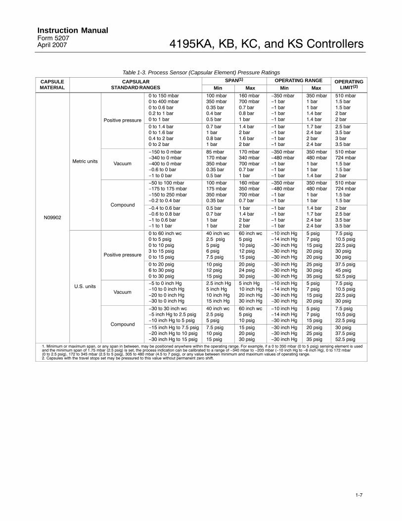
Table 1-3. Process Sensor (Capsular Element) Pressure Ratings
CAPSULEMATERIAL
CAPSULARSTANDARD RANGES
SPAN(1) OPERATING RANGE OPERATINGLIMIT(2)Min Max Min Max
N09902
Metric units
Positive pressure
0 to 150 mbar0 to 400 mbar0 to 0.6 bar0.2 to 1 bar0 to 1 bar
100 mbar350 mbar0.35 bar0.4 bar0.5 bar
160 mbar700 mbar0.7 bar0.8 bar1 bar
−350 mbar−1 bar−1 bar−1 bar−1 bar
350 mbar1 bar1 bar1.4 bar1.4 bar
510 mbar1.5 bar1.5 bar2 bar2 bar
0 to 1.4 bar0 to 1.6 bar0.4 to 2 bar0 to 2 bar
0.7 bar1 bar0.8 bar1 bar
1.4 bar2 bar1.6 bar2 bar
−1 bar−1 bar−1 bar−1 bar
1.7 bar2.4 bar2 bar2.4 bar
2.5 bar3.5 bar3 bar3.5 bar
Vacuum
−150 to 0 mbar−340 to 0 mbar−400 to 0 mbar−0.6 to 0 bar−1 to 0 bar
85 mbar170 mbar350 mbar0.35 bar0.5 bar
170 mbar340 mbar700 mbar0.7 bar1 bar
−350 mbar−480 mbar−1 bar−1 bar−1 bar
350 mbar480 mbar1 bar1 bar1.4 bar
510 mbar724 mbar1.5 bar1.5 bar2 bar
Compound
−50 to 100 mbar−175 to 175 mbar−150 to 250 mbar−0.2 to 0.4 bar
100 mbar175 mbar350 mbar0.35 bar
160 mbar350 mbar700 mbar0.7 bar
−350 mbar−480 mbar−1 bar−1 bar
350 mbar480 mbar1 bar1 bar
510 mbar724 mbar1.5 bar1.5 bar
−0.4 to 0.6 bar−0.6 to 0.8 bar−1 to 0.6 bar−1 to 1 bar
0.5 bar0.7 bar1 bar1 bar
1 bar1.4 bar2 bar2 bar
−1 bar−1 bar−1 bar−1 bar
1.4 bar1.7 bar2.4 bar2.4 bar
2 bar2.5 bar3.5 bar3.5 bar
U.S. units
Positive pressure
0 to 60 inch wc0 to 5 psig0 to 10 psig3 to 15 psig0 to 15 psig
40 inch wc2.5 psig5 psig6 psig7.5 psig
60 inch wc5 psig10 psig12 psig15 psig
−10 inch Hg−14 inch Hg−30 inch Hg−30 inch Hg−30 inch Hg
5 psig7 psig15 psig20 psig20 psig
7.5 psig10.5 psig22.5 psig30 psig30 psig
0 to 20 psig6 to 30 psig0 to 30 psig
10 psig12 psig15 psig
20 psig24 psig30 psig
−30 inch Hg−30 inch Hg−30 inch Hg
25 psig30 psig35 psig
37.5 psig45 psig52.5 psig
Vacuum
−5 to 0 inch Hg−10 to 0 inch Hg−20 to 0 inch Hg−30 to 0 inch Hg
2.5 inch Hg5 inch Hg10 inch Hg15 inch Hg
5 inch Hg10 inch Hg20 inch Hg30 inch Hg
−10 inch Hg−14 inch Hg−30 inch Hg−30 inch Hg
5 psig7 psig15 psig20 psig
7.5 psig10.5 psig22.5 psig30 psig
Compound
−30 to 30 inch wc−5 inch Hg to 2.5 psig−10 inch Hg to 5 psig
40 inch wc2.5 psig5 psig
60 inch wc5 psig10 psig
−10 inch Hg−14 inch Hg−30 inch Hg
5 psig7 psig15 psig
7.5 psig10.5 psig22.5 psig
−15 inch Hg to 7.5 psig−20 inch Hg to 10 psig−30 inch Hg to 15 psig
7.5 psig10 psig15 psig
15 psig20 psig30 psig
−30 inch Hg−30 inch Hg−30 inch Hg
20 psig25 psig35 psig
30 psig37.5 psig52.5 psig
1. Minimum or maximum span, or any span in between, may be positioned anywhere within the operating range. For example, if a 0 to 350 mbar (0 to 5 psig) sensing element is usedand the minimum span of 1.75 mbar (2.5 psig) is set, the process indication can be calibrated to a range of −340 mbar to −203 mbar (−10 inch Hg to −6 inch Hg), 0 to 172 mbar (0 to 2.5 psig), 172 to 345 mbar (2.5 to 5 psig), 305 to 480 mbar (4.5 to 7 psig), or any value between minimum and maximum values of operating range.2. Capsules with the travel stops set may be pressured to this value without permanent zero shift.

4195KA, KB, KC, and KS ControllersInstruction Manual
Form 5207April 2007
1-8
Table 1-4. Process Sensor (Bourdon Tube) Pressure Ratings and Materials
BOURDON TUBESSPAN(1) OPERATING RANGE(2) OPERATING
LIMITS(4)STANDARDMATERIALMinimum Maximum Minimum Maximum(3)
Bar
Metric units
0 to 1.60 to 2.50 to 40 to 6
1223.5
2447
−1−1−1−1
366
10
3.36.66.611
S31600 (316 SST)
0 to 100 to 160 to 250 to 40
7102020
14204040
−1−100
20306060
22336666
0 to 600 to 1000 to 1600 to 300
5576
160250
70100200350
0000
90135270420
103155310482
Psig Psig Psig Inch Hg Psig Psig STANDARDMATERIAL
U.S. units
0 to 300 to 600 to 1000 to 200
153050
100
3060
100200
−30−30−30−30
4284
140280
4896
160320
S31600 (316 SST)0 to 3000 to 6000 to 10000 to 1500
150300750
1100
300600
10001500
−30000
420840
13001950
480960
15002250
0 to 30000 to 5000
22003700
30005000
00
39006000
45007000
1. Minimum or maximum span, or any span in between, may be positioned anywhere within the operating range. For example, if a 0 to 2 bar (0 to 30 psig) sensing element is usedand the minimum span of 1 bar (15 psig) is set, the process indication can be calibrated to a range of −1 to 0 bar (−30 inch Hg to 0 psig), 0 to 1 bar (0 to 15 psig), 1 to 2 bar (15 to 30psig), 2 to 3 bar (27 to 42 psig) or any value between the operating range minimum and maximum values.2. Travel stops should be used when the maximum or minimum process pressure will be 5% over or under the calibrated range. For example, a 0 to 2 bar (0 to 30 psig) sensingelement is calibrated for 0.7 to 2 bar (10 to 30 psig), the desired range. The minimum expected pressure is 0 psig and the maximum expected pressure is 2.8 bar (40 psig). Travelstops must be used to prevent excessive overtravel and undertravel since the maximum allowable overpressure and underpressure is higher than 5% of the 1.4 bar (20 psig) spanwhich is ±70 mbar (±1 psig).3. Bourdon tube without travel stops may be pressured to this value without permanent zero shift.4. Bourdon tube with travel stops set may be pressured to this value without permanent zero shift.
Table 1-5. Optional Process ConnectionsINPUT RANGE CONNECTION
Bar Psig Size Material
Up to0 to 400
Up to0 to 5000
� 1/2 NPT externalor � 1/2 NPTinternal
� Steel or
� stainlesssteel
0 to 400 to0 to 600
0 to 5000 to0 to 10,000
1/2 NPT internal Stainless steel
0 to 400 to0 to 600
0 to 5000 to0 to 10,000
1/2 NPT external Stainless steel
Table 1-6. Supply Pressure DataOUTPUT SIGNAL
RANGENORMAL
OPERATINGSUPPLY
PRESSURE(1)
MAXIMUMPRESSURE LIMIT(2)
Bar0.2 to 1.0 1.4 2.8
0.4 to 2.0 2.4 2.8
Psig3 to 15 20 40
6 to 30 35 401. If this pressure is exceeded, control may be impaired.2. If this pressure is exceeded, damage to the controller may result.
4195KA, KB, KC, and KS ControllersInstruction ManualForm 5207April 2007
2-1
Section 2 Installation
WARNING
To avoid personal injury or propertydamage resulting from the suddenrelease of pressure:
� Always wear protective clothing,gloves, and eyewear when performingany installation operations.
� Personal injury or propertydamage may result from fire orexplosion if natural gas is used as thesupply medium and preventativemeasures are not taken. Preventativemeasures may include: Remoteventing of the unit, re-evaluating thehazardous area classification,ensuring adequate ventilation, and theremoval of any ignition sources. Forinformation on remote venting of thiscontroller, refer to page 2-5.
� Check with your process orsafety engineer for any additionalmeasures that must be taken toprotect against process media.
� If installing into an existingapplication, also refer to theWARNING at the beginning of theMaintenance section of thisinstruction manual.
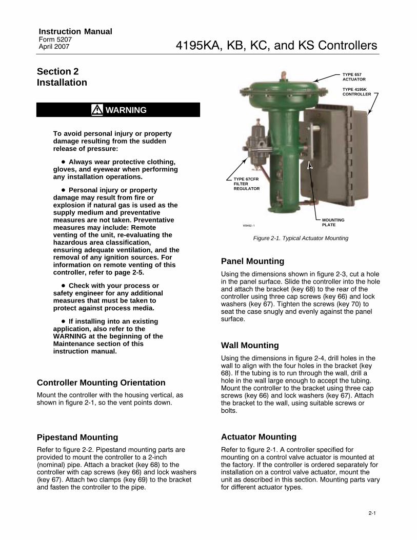
Controller Mounting OrientationMount the controller with the housing vertical, asshown in figure 2-1, so the vent points down.
Pipestand MountingRefer to figure 2-2. Pipestand mounting parts areprovided to mount the controller to a 2-inch(nominal) pipe. Attach a bracket (key 68) to thecontroller with cap screws (key 66) and lock washers(key 67). Attach two clamps (key 69) to the bracketand fasten the controller to the pipe.
MOUNTINGPLATE
TYPE 657ACTUATOR
TYPE 4195KCONTROLLER
TYPE 67CFRFILTERREGULATOR
W8462−1
Figure 2-1. Typical Actuator Mounting
Panel MountingUsing the dimensions shown in figure 2-3, cut a holein the panel surface. Slide the controller into the holeand attach the bracket (key 68) to the rear of thecontroller using three cap screws (key 66) and lockwashers (key 67). Tighten the screws (key 70) toseat the case snugly and evenly against the panelsurface.
Wall MountingUsing the dimensions in figure 2-4, drill holes in thewall to align with the four holes in the bracket (key68). If the tubing is to run through the wall, drill ahole in the wall large enough to accept the tubing.Mount the controller to the bracket using three capscrews (key 66) and lock washers (key 67). Attachthe bracket to the wall, using suitable screws orbolts.
Actuator MountingRefer to figure 2-1. A controller specified formounting on a control valve actuator is mounted atthe factory. If the controller is ordered separately forinstallation on a control valve actuator, mount theunit as described in this section. Mounting parts varyfor different actuator types.

4195KA, KB, KC, and KS ControllersInstruction Manual
Form 5207April 2007
2-2
49A3196-AA6732 / IL
HEX HEADCAP SCREW(KEY 66)
LOCKWASHER(KEY 67)
HEX NUT(KEY 364)
LOCKWASHER(KEY 363)
PIPE CLAMP(KEY 69)
LOCKWASHER(KEY 363)
HEX NUT(KEY 364)
HEX HEADCAP SCREW(KEY 66)
LOCKWASHER(KEY 67)
HEX HEADCAP SCREW(KEY 362)
BRACKET(KEY 68)
ELBOW(KEY 365)
REGULATOR
HEX HEADCAP SCREW(KEY 362)
BRACKET(KEY 68)
ELBOW(KEY 365)
PIPE CLAMP(KEY 69)
VERTICAL PIPE
HORIZONTAL PIPE
Figure 2-2. Pipestand Mounting
Attach the mounting bracket to the actuator yokewith cap screws, lock washers, and spacer spools.Attach the controller to the bracket with cap screws,lock washers, and spacer spools. On some designs,the mounting bracket is attached to the actuatorcasing rather than to the yoke.
Pressure Connections
WARNING
To avoid personal injury or propertydamage resulting from the suddenrelease of pressure, do not install any
system component where serviceconditions could exceed the limitsgiven in this manual. Usepressure-relieving devices as requiredby government or accepted industrycodes and good engineeringpractices.
Refer to figure 2-5 for pressure connection locations.Supply, output, remote set point, external feedback,and vent connections are 1/4 NPT, internal. Processpressure connections are 1/4 or 1/2 NPT (optional).Use 1/4-inch or 3/8-inch pipe or tubing for supply,output, remote set point, and external feedbackconnections.
4195KA, KB, KC, and KS ControllersInstruction ManualForm 5207April 2007
2-3
HEX HEADCAP SCREW(KEY 66)
LOCKWASHER(KEY 67)
ROUNDHEADMACHINESCREW(KEY 70)
BRACKET(KEY 68)
TOP VIEW
36A9760-AA6733 / IL
84(3.29)
63(2.49)
306(12.06)
14 R(0.56)
236(9.31)
mm(INCH)
13(0.50)
62(2.43)
REAR VIEW DIMENSIONS OFPANEL CUTOUT
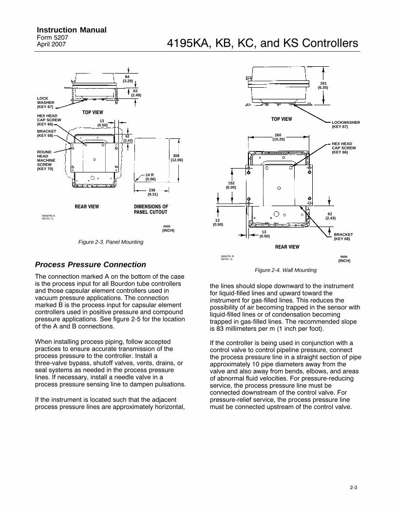
Figure 2-3. Panel Mounting
Process Pressure ConnectionThe connection marked A on the bottom of the caseis the process input for all Bourdon tube controllersand those capsular element controllers used invacuum pressure applications. The connectionmarked B is the process input for capsular elementcontrollers used in positive pressure and compoundpressure applications. See figure 2-5 for the locationof the A and B connections.
When installing process piping, follow acceptedpractices to ensure accurate transmission of theprocess pressure to the controller. Install athree-valve bypass, shutoff valves, vents, drains, orseal systems as needed in the process pressurelines. If necessary, install a needle valve in aprocess pressure sensing line to dampen pulsations.
If the instrument is located such that the adjacentprocess pressure lines are approximately horizontal,
HEX HEADCAP SCREW(KEY 66)
LOCKWASHER(KEY 67)
BRACKET(KEY 68)
TOP VIEW
36A9761-BA6734 / IL
161(6.35)
260(10.25)
152(6.00)
62(2.43) 13
(0.50)
REAR VIEW
mm(INCH)
13(0.50)
Figure 2-4. Wall Mounting
the lines should slope downward to the instrumentfor liquid-filled lines and upward toward theinstrument for gas-filled lines. This reduces thepossibility of air becoming trapped in the sensor withliquid-filled lines or of condensation becomingtrapped in gas-filled lines. The recommended slopeis 83 millimeters per m (1 inch per foot).
If the controller is being used in conjunction with acontrol valve to control pipeline pressure, connectthe process pressure line in a straight section of pipeapproximately 10 pipe diameters away from thevalve and also away from bends, elbows, and areasof abnormal fluid velocities. For pressure-reducingservice, the process pressure line must beconnected downstream of the control valve. Forpressure-relief service, the process pressure linemust be connected upstream of the control valve.

4195KA, KB, KC, and KS ControllersInstruction Manual
Form 5207April 2007
2-4
Supply Pressure Connection
WARNING
Severe personal injury or propertydamage may occur if the instrumentair supply is not clean, dry andoil-free, or noncorrosive gas. Whileuse and regular maintenance of a filterthat removes particles larger than 40microns in diameter will suffice inmost applications, check with anEmerson Process Management fieldoffice and industry instrument airquality standards for use withcorrosive gas or if you are unsureabout the proper amount or method ofair filtration or filter maintenance.
Supply pressure must be clean, dry air ornoncorrosive gas that meets the requirements ofISA Standard S7.3. Use a suitable supply pressureregulator to reduce the supply pressure source tothe normal operating supply pressure shown in table1-6. Connect supply pressure to the SUPPLYconnection on the bottom of the case, shown infigure 2-5.
Remote Set Point (suffix letter M)Pressure ConnectionIf the controller has remote set point (suffix letter M),connect the remote set point pressure to the top ofthe controller case at the location shown in figure2-5. Use clean, dry air or noncorrosive gas. Use a0.2 to 1.0 bar (3 to 15 psig) remote set pointpressure range for a 0.2 to 1.0 bar (3 to 15 psig)controller output signal range or a 0.4 to 2.0 bar (6to 30 psig) remote set point pressure range for a 0.4to 2.0 bar (6 to 30 psig) controller output signalrange. If pressure is supplied to the remote set pointconnection with a regulator, a small bleed orificeshould be placed between the regulator and remoteset point connection to prevent pressure variationsdue to regulator lock-up.
260(10.25)
102(4.00)
130(5.13)
51(2.00)
330(13.00)
3.44(87)
10.04(255)
5/16UNC-283 HOLES(MOUNTING)
1/4-18 NPTCONTROLLER OUTPUTCONNECTION
1/4-18 NPTSUPPLY PRESSURECONNECTION
1/4 NPTREMOTE SET POINTCONNECTION
147(5.80) 66
(2.56)
31(1.22)
1/4 NPT 4 HOLES
1/4-18NPT VENTCONNECTION
mm(INCH)
FRONT VIEW REAR VIEW
BOTTOM VIEW TOP VIEW
NOTES: 1/4-18 NPT PROCESS CONNECTION (MARKED A) FOR ALL
BOURDON TUBE CONTROLLERS AND FOR THOSE CAPSULAR ELEMENT CONTROLLERS USED IN VACUUM PRESSURE APPLICATIONS.
1/4-18 NPT PROCESS CONNECTION (MARKED B) FOR CAPSULAR ELEMENT CONTROLLERS USED IN POSITIVE AND COMPOUND PRESSURE APPLICATIONS.
FOR THE EXTERNAL FEEDBACK CONNECTIONS (4195KB CONTROLLERSONLY), EITHER THE A OR B CONNECTION IS USED, DEPENDING ON THE LOCATION OF THE PROCESS CONNECTION.
1
46A9765-AA2892-4 / IL
2
3
Figure 2-5. Connection Locations
External Feedback Pressure Connection(4195KB Series Controllers Only)
When a secondary controller in an overrideapplication has this option, reset windup isminimized in the secondary controller. Connect theexternal feedback connection of the secondarycontroller to the output of the customer-supplied highor low select relay (see figures 2-5 and 4-9).
4195KA, KB, KC, and KS ControllersInstruction ManualForm 5207April 2007
2-5
Vent
WARNING
Personal injury or property damagecould result from fire or explosion ofaccumulated gas, or from contact withhazardous gas, if a flammable orhazardous gas is used as the supplypressure medium. Because thecontroller case and cover assembly donot form a gas-tight seal when theassembly is enclosed, a remote ventline, adequate ventilation, andnecessary safety measures should beused to prevent the accumulation offlammable or hazardous gas.However, a remote vent pipe alonecannot be relied upon to remove allflammable or hazardous gas. Vent linepiping should comply with local andregional codes and should be as shortas possible with adequate insidediameter and few bends to reducecase pressure buildup.
CAUTION
When installing a remote vent pipe,take care not to over-tighten the pipein the vent connection. Excessivetorque will damage the threads in theconnection.
If a remote vent is required, the vent line must be asshort as possible with a minimum number of bendsand elbows. Vent line piping should have a minimuminside diameter of 19 mm (3/4 inches) for runs up to6.1 meters (20 feet) and a minimum inside diameterof 25 mm (1 inch) for runs from 6.1 to 30.5 meters(20 to 100 feet).
The vent must be protected against the entrance ofany foreign material that could plug it; or if a remotevent is not required, the vent opening in the casemust be protected against the entrance of anyforeign material that could plug it. Check the ventperiodically to be certain it is not plugged.

4195KA, KB, KC, and KS ControllersInstruction Manual
Form 5207April 2007
2-6

4195KA, KB, KC, and KS ControllersInstruction ManualForm 5207April 2007
3-1
METAL BALL
SWITCHING ZONEINDICATOR
LOADER KNOB
AUTO/MANUALSWITCH
W3679 / IL
AUTO/MANUAL STATION(SUFFIX LETTER E)
SET POINTINDICATOR
PROCESS POINTER
PROPORTIONAL BANDADJUSTMENT
PROPORTIONAL BANDINDICATOR COVER
OUTPUT PRESSUREGAUGE
W6832 / IL
Figure 3-1. 4195KA Series Controller Adjustment Locations
Section 34195KA Series Proportional-OnlyControllers
Adjustments for 4195KA SeriesControllersThis section includes descriptions of adjustmentsand procedures for prestartup, startup, andcalibration. Adjustment locations are shown infigures 3-1 and 3-3. To better understand theadjustments and overall controller operation, refer tothe Principle of Operation section and the schematicdiagrams in figures 3-4 and 3-5. Unless otherwisenoted, key numbers given in this section are found infigure 7-1.
Manual Set Point Adjustment
Adjust the set point by moving the set point indicatoruntil the line on the set point indicator is over thedesired value on the process pressure scale. Movethe indicator to the right to increase the set point andto the left to decrease it. Adjusting the set point doesnot affect the proportional band setting.
Remote Set Point (suffix letter M)Adjustment
CAUTION
Do not manually move the set pointindicator on controllers with remoteset point. Manually moving the setpoint indicator could damage thecontroller.
If the controller is equipped with remote set point(suffix letter M), vary the remote set point pressureto change the set point. Increase the pressure toincrease the set point, and decrease the pressure todecrease the set point.
Proportional Band Adjustment (PB ADJ)The proportional band determines the controlleroutput sensitivity. The proportional band adjustmentis marked in percentages of process pressurerequired to drive the controller from zero output tofull output.

4195KA, KB, KC, and KS ControllersInstruction Manual
Form 5207April 2007
3-2
W3439 / IL
Figure 3-2. Changing Controller Action on4195KA Series Controllers
To adjust the proportional band, open the controllercover and locate the proportional band adjustment(PB ADJ) knob. Rotate the knob until the desiredvalue is opposite the line on the proportional bandindicator cover.
Changing Controller ActionTo change the controller action from direct toreverse or vice versa, loosen the screws on theproportional band indicator cover. Lift the cover outas shown in figure 3-2 and rotate the proportionalband adjustment to the desired action. Setting theproportional band to the values in the white portionof the adjustment provides direct controller action;setting proportional band in the black portionprovides reverse controller action.
Bourdon Tube or Capsular Element Controllersfor Positive or Compound Pressure
� For direct control action:
An increasing sensed pressure increases outputpressure.
� For reverse control action:
An increasing sensed pressure decreases outputpressure.
Capsular Element Controllers for VacuumPressure
� For direct control action:
An increasing sensed vacuum increases outputpressure.
� For reverse control action:
An increasing sensed vacuum decreases outputpressure.
After changing the action, tighten the screws on theproportional band indicator cover.
Switching The Auto/Manual Station(suffix letter E)
Note
Switching the controller betweenautomatic and manual, or manual andautomatic mode, without balancingthe outputs, can disturb the processand cause controller cycling.
Refer to figure 3-1 if the controller has theauto/manual station (suffix letter E). To switch fromautomatic to manual mode, or from manual toautomatic, you must first balance the manual outputwith the controller output. Two balance methods areavailable to equalize the manual output with thecontroller output.
To switch from automatic to manual mode, carefullyadjust the loader knob until the metal ball inside theplastic tube moves into the switching zone. Thenmove the automatic/manual switch to MANUAL.Turn the loader knob clockwise to increase thecontroller output or counterclockwise to decrease it.
To switch from manual to automatic mode, adjustthe set point to move the ball into the switchingzone. Turn the switch to AUTO and adjust the setpoint to control the output.
When the auto/manual switch is in AUTO, adjustingthe loader knob has no effect on the controlleroutput. When the auto/manual switch is in MANUAL,changing the set point has no effect on the controlleroutput.
Prestartup Checks for 4195KA SeriesControllersRefer to figure 3-1 for adjustment locations and referto figure 7-1 for key number locations.
When performing the checks, open loop conditionsmust exist. An open loop exists when the controlleroutput does not affect the input pressure or othercontrol signal to the controller.

4195KA, KB, KC, and KS ControllersInstruction ManualForm 5207April 2007
3-3
Note
If the controller has the auto/manualstation (suffix letter E), be sure thecontroller is in the automatic modebefore performing the prestartupchecks.
1. Provide a means of measuring the controlleroutput pressure by connecting the controller outputto a pressure gauge. Connect supply pressure to thesupply pressure regulator and be sure it is deliveringthe proper supply pressure to the controller. Do notexceed the normal operating pressure in table 1-6.
2. For a controller with remote set point (suffix letterM), connect regulated pressure of 0.2 to 1.0 bar (3to 15 psig) or 0.4 to 2.1 bar (6 to 30 psig) to theremote set point connection at the top of thecontroller case.
3. Remove the two machine screws (key 6) and liftoff the proportional band indicator cover (key 36).
4. Adjust the set point a minimum of 20 percent ofinput span above the process pointer.
5. Adjust the proportional band for 5 percentDIRECT.
6. If necessary, connect a pressure source to theprocess connection and adjust the process pointerto the last mark on the left side of the scale. If thelast scale mark is 0 psig, a pressure source is notrequired.
7. The controller output pressure should be 0 bar (0psig).
8. Rotate the proportional band to 5 percentREVERSE.
9. The controller output should be within 0.14 bar (2psig) of the supply pressure.
10. If the controller output is within tolerance, adjustthe proportional band to 400 percent in the desiredaction, secure the proportional band indicator cover(key 36) with the machine screws (key 6), and go tothe startup procedure. If the controller outputpressure is not within tolerance, go to the 4195KASeries calibration procedure for recalibration.
Startup for 4195KA Series Controllers
Perform the prestartup checks and, if necessary,calibrate the controller prior to this procedure.
Note
When performing the startupprocedures, keep in mind that theinitial settings are guidelines. Theywill vary depending on the actualprocess being controlled.
1. Be sure the supply pressure regulator isdelivering the proper supply pressure to thecontroller.
2. For controllers with:
Manual set point:
Move the set point adjustment to the desired setpoint.
Remote set point:
a. See figure 2-5 for the location of the remoteset point connection. Connect an adjustablepressure source to the remote set pointconnection.
b. Adjust the pressure source until the set pointindicator reaches the desired set point.Remember: Increasing the remote set pointpressure increases the set point.
3. Set the proportional band adjustment to 100percent for fast processes. For slow processes,calculate the proportional band percentage from theequation below:
P.B. � 200 � Allowable OvershootPressure Span
For example:
200 � 0.14 bar2.1 bar
� 13%
4. Create a load upset by momentarily changing theset point. Check for system cycling. If the systemdoes not cycle, lower the proportional band setting(thus raising the gain) and disturb the system againby changing the set point. Continue this procedureuntil the system cycles. At this point, double theproportional band setting (proportional band setting×2).
5. Check the stability of the recommendedproportional band setting by introducing adisturbance and monitoring the process.
4195KA, KB, KC, and KS ControllersInstruction Manual
Form 5207April 2007
3-4
Calibration of 4195KA SeriesControllers
WARNING
To avoid personal injury or propertydamage resulting from the suddenrelease of pressure, do not exceed theoperating limits given in this manual.
General Calibration Instructions
Note
If the controller has the auto/manualstation (suffix letter E), be sure thecontroller is in the automatic modebefore performing calibration.
If the prestartup checks, or startup, reveal faultycontroller operation, perform the calibrationdescribed in this section. These instructions arevalid for either shop or field calibration, provided thatopen process loop conditions exist. Unlessotherwise noted, key numbers are found in figure 7-1.
Do not use the gauges supplied with the controllerduring calibration. Monitor process pressure, supplypressure, controller output pressure, and ifapplicable, remote set point pressure with externalgauges.
Process Indicator Zero and SpanCalibrationBefore starting this procedure:
� Provide a regulated process pressure to thecontroller and a means of measurement external tothe controller.
� Provide a means of measuring the controlleroutput pressure by connecting the controller outputto a pressure gauge (open loop conditions mustexist). Provide a regulated supply pressure to thecontroller. Do not exceed the normal operatingpressure in table 1-6.
Refer to figures 3-1 and 3-3 for adjustmentlocations.
Note
Any change to the process pointerspan adjustment will require
readjustment of the process pointerzero adjustment.
1. Remove the two screws (key 6) and lift off theproportional band indicator cover (key 36).
2. Set the proportional band between DIRECT andREVERSE.
3. Apply process pressure equal to the processscale span lower limit.
4. The process pointer should indicate the processscale lower limit. If not, adjust the process pointer tothe process scale lower limit by loosening the zeroadjustment locking screw and turning the zeroadjustment screw. Tighten the zero adjustmentlocking screw.
5. Apply process pressure equal to the processscale span upper limit.
6. The process pointer should indicate the processscale upper limit. If not, adjust the span screw tocorrect one-half of the error as follows: clockwise toincrease span for a low indication (below the upperlimit); counterclockwise to decrease span for a highindication (above the upper limit).
7. Repeat steps 3 through 6 until the error iseliminated.
8. Apply process pressure equal to the mid-scalevalue of the process scale span. The processpointer should indicate the mid-scale mark, ±2percent of span. If the error is greater than ±2percent, refer to the Maintenance section andperform the appropriate zero and span adjustmentprocedure for a Bourdon tube or capsular elementcontroller.
9. Adjust the process pointer to within ±1 percent ofthe mid-scale mark by loosening the locking screwand turning the zero adjustment screw. Thisdistributes the error over the entire scale span andbrings all points within ±1 percent of the processinput span.
10. Apply process pressure equal to the processscale span lower limit.
11. The process pointer should indicate the processscale lower limit ±1 percent of the scale span.
12. Apply process pressure equal to the processscale span upper limit.
13. The process pointer should indicate the processscale upper limit ±1 percent of the scale span.
14. If the error is greater than ±1 percent, repeatsteps 3 through 13.

4195KA, KB, KC, and KS ControllersInstruction ManualForm 5207April 2007
3-5
PROCESSPOINTER SPANADJUSTMENT
REMOTE SET POINTSPAN ADJUSTMENT(SUFFIX LETTER M)
SCREW 1
SCREW 2
SCREW 3
SIDE VIEW OF SET POINT/PROCESS INDICATOR ASSEMBLY
SIDE VIEW OF CONTROLLERSHOWING FLAPPER LEVELING SCREWS
56A9752-S SHT 1
39A1126-B
A6730 / IL
POINTER ZEROADJUSTMENT
POINTER ZEROADJUSTMENTLOCKING SCREW
PROCESS POINTERSPAN ADJUSTMENT
REMOTE SET POINTZERO ADJUSTMENTLOCKING SCREW(SUFFIX LETTER M)
REMOTE SET POINTZERO ADJUSTMENT(SUFFIX LETTER M)
FRONT VIEW
W6832 / IL
Figure 3-3. 4195KA Series Controller Calibration Adjustment Locations

4195KA, KB, KC, and KS ControllersInstruction Manual
Form 5207April 2007
3-6
Remote Set Point (suffix letter M) Zeroand Span CalibrationRefer to figures 3-1 and 3-3 for adjustmentlocations. Refer to figure 7-1 for key numberlocations.
Note
Any adjustment of the remote setpoint span adjustment screw requiresreadjustment of the remote set pointzero adjustment screw.
1. Remove the two screws (key 6) and lift off theproportional band indicator cover (key 36).2. Set the proportional band between DIRECT andREVERSE.3. Apply remote set point pressure equal to thelower range limit.4. The set point indicator should indicate theprocess scale lower limit. If not, loosen the remoteset point zero adjustment locking screw and adjustthe remote set point zero adjustment screw until theset point indicator aligns with the process scalelower limit. Tighten the zero adjustment lockingscrew.5. Apply remote set point pressure equal to theupper range limit.6. The set point indicator should indicate theprocess scale upper limit. If not, adjust the remoteset point span adjustment screw to correct one-halfthe error as follows: clockwise to increase span for alow indication; counterclockwise to decrease spanfor a high indication.7. Repeat steps 3 through 6 until the error iseliminated.8. Apply remote set point pressure equal to themid-range value.9. Make sure the set point indicator is within ±1percent of the mid-scale mark and if so, proceed tostep 12. If the set point indicator is not within 1percent, but is within ±2 percent of the mid-scalemark, then proceed with step 10. If the set pointindicator is not within ±2 percent, proceed to theremote set point calibration procedure in theMaintenance section.10. Loosen the remote set point zero adjustmentlocking screw and adjust the remote set point zeroadjustment screw to correct for half the error atmid-scale. Tighten the zero adjustment lockingscrew.
11. Apply remote set point pressure equal to thelower and upper range limits and make sure the setpoint indicator is within ±1 percent.
12. If necessary, perform the process indicator zeroand span calibration procedure in this section.Otherwise, perform the flapper alignment procedurein this section.
Flapper Alignment
Note
Perform the process indicator zeroand span calibration procedure and,for controllers with remote set point(suffix letter M), the remote set pointzero and span calibration procedurebefore the flapper alignment.
Flapper leveling screw numbers and adjustmentsare shown in figure 3-3. Key number locations areshown in figure 7-1.
Provide a means of measuring the controller outputpressure by connecting the controller output to apressure gauge (open-loop conditions must exist).Provide a regulated supply pressure to thecontroller. Do not exceed the normal operatingpressure in table 1-6. After performing the flapperalignment procedure, go to the startup procedure.
1. For a controller with manual set point, move theset point indicator to the mid-scale mark on theprocess scale. For a controller with remote set point(suffix letter M), adjust the remote set point pressureuntil the set point indicator is at the mid-scale markon the process scale.2. Apply process pressure equal to the mid-scalevalue of the process scale span. If pressure is notavailable to pressure the input element to themid-scale value, an alternate method is todisconnect link number 1 at the input element andtape the process pointer at the mid-scale mark onthe process scale. If the controller has a capsularinput element, note the hole from which link number1 was removed for proper replacement. This methodshould only be used if pressure is not available topressure the input element to the mid-scale value.3. Remove the two machine screws (key 6) and liftoff the proportional band indicator cover (key 36).4. Adjust the proportional band between DIRECTand REVERSE.5. The controller output should be 0.62 ±0.007 bar(9 ±0.10 psig) for a 0.2 to 1.0 bar (3 to 15 psig)output or 1.2 ±0.01 bar (18 ±0.2 psig) for a 0.4 to 2.0bar (6 to 30 psig) output. If not, adjust flapperleveling screw 2 (the screw nearest the nozzle) untilthe output is within tolerance.6. Set the proportional band to 30 percent DIRECT.

4195KA, KB, KC, and KS ControllersInstruction ManualForm 5207April 2007
3-7
SET POINT INDICATOR RESET BELLOWS (VENTED) REVERSE ACTIONQUADRANT
PROPORTIONALBELLOWS PROPORTIONAL
BAND ADJUSTMENT
FLAPPER PIVOT
DIRECT ACTIONQUADRANT
FLAPPER
NOZZLE
BEAM
CONNECTINGLINK
PROCESS POINTER
REMOTE SET POINTCONNECTED HERE
INPUT ELEMENTCONNECTED HERE
SUPPLYPRESSURE
RELAY
OUTPUT PRESSURETO FINAL CONTROLELEMENT
SUPPLY PRESSURE
OUTPUT PRESSURE
PROPORTIONAL PRESSURE
NOZZLE PRESSURE
FEEDBACKLINK
FEEDBACKMOTION
INPUTMOTION
FLAPPER DETAIL
46A9764-AB1489-2 / IL
Figure 3-4. 4195KA Series Controller Schematic
7. The controller output should be 0.62 ±0.02 bar (9±0.25 psig) or 1.2 ±0.04 bar (18 ±0.5 psig). If not,adjust flapper leveling screw 3 (the screw nearestthe nozzle).
8. Set the proportional band to 30 percentREVERSE.
9. The controller output should be 0.62 ±0.02 bar (9±0.25 psig) or 1.2 ±0.04 bar (18 ±0.5 psig). If not,adjust flapper leveling screw 1 (the screw nearestthe nozzle).
10. Repeat steps 4 through 9 until the controlleroutput remains in tolerance without further levelingscrew adjustments.
11. If link 1 was disconnected, remove the tape andreconnect link 1 to the input element.
12. Set the proportional band to 400 percent in thedesired controller action and replace the proportionalband indicator cover.
Principle of Operation for 4195KASeries Controllers
Overall OperationRefer to the schematic diagram in figure 3-4.
The input element is connected to the processpointer and to the flapper by connecting links. As theprocess pressure increases (in a direct-actingcontroller), the flapper moves toward the nozzle,restricting flow through the nozzle and increasingnozzle pressure. When this occurs, relay actionincreases the output pressure (delivery) of thecontroller. Output pressure is fed back to theproportional bellows. The action of the proportionalbellows counteracts the flapper movement thatresulted from the process pressure change andbacks the flapper away from the nozzle untilequilibrium is reached.
Moving the set point indicator changes the distancebetween the nozzle and flapper as does a change inprocess pressure, except that when the set point ischanged, the nozzle moves with respect to theflapper.
The proportional band adjustment positions thenozzle on the flapper. Increasing (widening) theproportional band moves the nozzle to a position on

4195KA, KB, KC, and KS ControllersInstruction Manual
Form 5207April 2007
3-8
AUTOMATICPOSITION
OUTPUT PRESSURETO FINAL CONTROLELEMENT
SUPPLYPRESSURE
RELAY
AUTO/MANUALSWITCH
MANUAL LOADER
MANUALLOADERKNOB
MANUALPOSITION
AUTO/MANUALSWITCH
OUTPUT PRESSURETO FINAL CONTROLELEMENT
PLASTICTUBE
METAL BALL
RELAY OUTPUT PRESSURE
SUPPLY PRESSURE
MANUAL LOADER OUTPUT PRESSURE
48A5230-AA2999-1 / IL
Figure 3-5. 4195KA Series Auto/Manual Station Schematic
the flapper where less input and more feedbackmotion occurs, which decreases the gain of thecontroller. Decreasing (narrowing) the proportionalband moves the nozzle toward a position wheremore input and less feedback motion occurs, whichincreases the gain. The controller action is changedfrom direct to reverse by turning the proportionalband adjustment to position the nozzle on theflapper quadrant to a point where the direction of theflapper motion versus input motion is reversed asshown in the flapper detail of figure 3-4. With thecontroller in the reverse-acting mode, an increase inprocess pressure causes a decrease in outputpressure.
Remote Set Point (suffix letter M)OperationThe capability to adjust the controller set point froma remote location is available with all 4195KA Seriescontrollers. This option is designated by the letter Min the type number.
A control pressure is applied to the capsular elementwithin the remote set point assembly. The expansionand contraction of the capsule moves the set pointadjustment via a connecting linkage. Increasing thecontrol pressure to the capsule increases the setpoint setting and decreasing the control pressurereduces the set point setting.
Auto/Manual Station (suffix letter E)OperationA controller with the auto/manual station (designatedby the suffix letter E in the type number) has pipingon the output side of the relay as shown in figure3-5. Supply pressure to the relay is also applied tothe manual loader. The manual loader, functioningas a regulator, applies pressure to one side of theplastic tube and to the auto/manual switch. Outputpressure from the relay registers on the other side ofthe plastic tube as well as in the auto/manual switch.
When the auto/manual switch is in the MANUALposition, the manual loader output is channeledthrough the auto/manual switch and becomes thecontroller output. When the auto/manual switch is inthe AUTO position, the relay output is channeledthrough the switch to become the controller output.
Before the auto/manual switch is operated, the relayoutput must equal the manual loader output to avoidbumping the process. Adjusting the set point variesthe pressure on the left-hand side of the plastic tube.Adjusting the manual loader knob varies thepressure on the right-hand side. When the pressuresare equal, the metal ball is centered in the tube andit is held in place by a small magnet. A pressureimbalance forces the ball to one end of the tubewhere it forms a seal, blocking air flow through thetube.
4195KA, KB, KC, and KS ControllersInstruction ManualForm 5207April 2007
4-1
METAL BALL
SWITCHING ZONEINDICATOR
LOADER KNOB
AUTO/MANUALSWITCH
W3679 / IL
AUTO/MANUAL STATION(SUFFIX LETTER E)
RATEADJUSTMENT RESET
ADJUSTMENTW3599−1 / IL
4195KC RESET AND RATE ADJUSTMENTS
SET POINTINDICATOR
TYPICAL ADJUSTMENTS4195KB SHOWNW6833 / IL
PROCESS POINTER
PROPORTIONAL BANDADJUSTMENT
ANTI-RESET WINDUPDIFFERENTIAL RELIEFVALVE (SUFFIX LETTER F)
SUPPLYPRESSURE GAUGE
RESETADJUSTMENT
OUTPUT PRESSUREGAUGE
Figure 4-1. 4195KB and KC Series Controller Adjustment Locations
Section 4 4195KB Series Proportional-Plus-Reset Controllers and 4195KCSeries Proportional-Plus-Reset-Plus-Rate Controllers
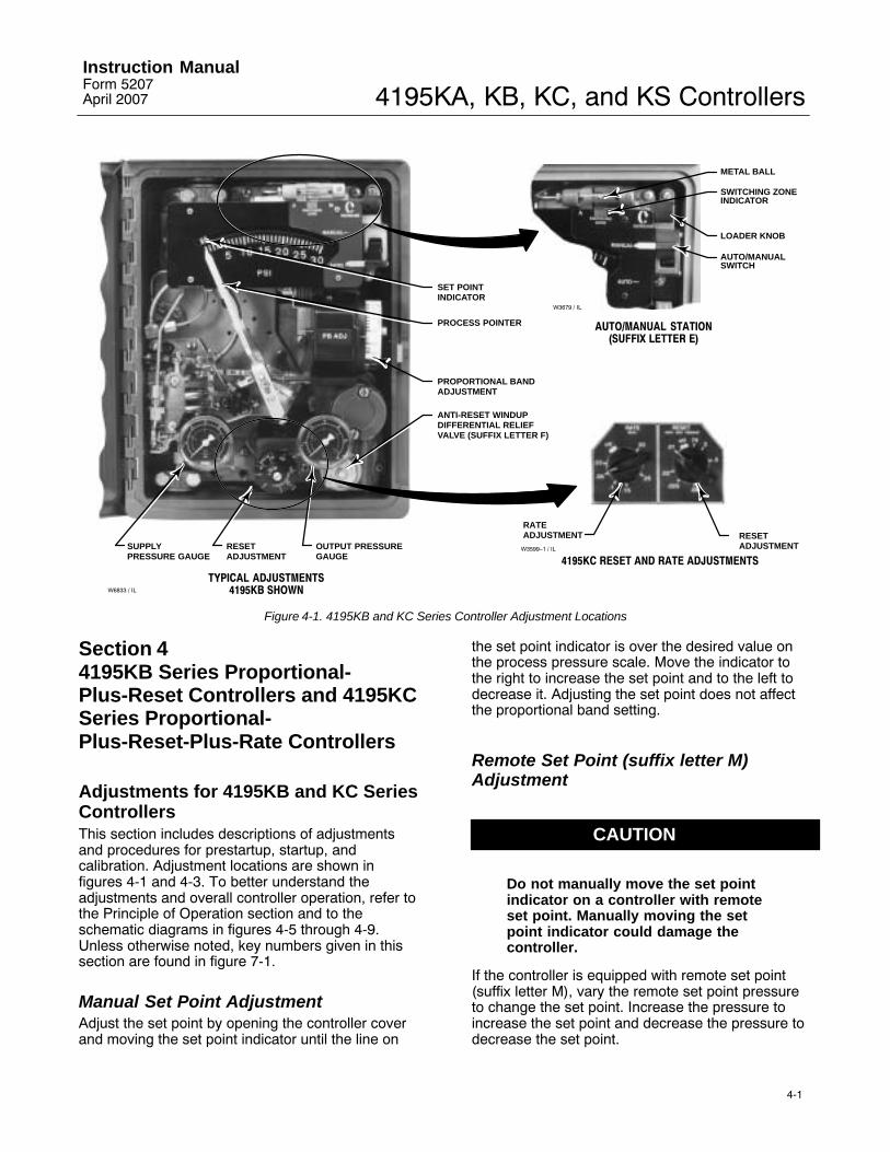
Adjustments for 4195KB and KC SeriesControllersThis section includes descriptions of adjustmentsand procedures for prestartup, startup, andcalibration. Adjustment locations are shown infigures 4-1 and 4-3. To better understand theadjustments and overall controller operation, refer tothe Principle of Operation section and to theschematic diagrams in figures 4-5 through 4-9.Unless otherwise noted, key numbers given in thissection are found in figure 7-1.
Manual Set Point AdjustmentAdjust the set point by opening the controller coverand moving the set point indicator until the line on
the set point indicator is over the desired value onthe process pressure scale. Move the indicator tothe right to increase the set point and to the left todecrease it. Adjusting the set point does not affectthe proportional band setting.
Remote Set Point (suffix letter M)Adjustment
CAUTION
Do not manually move the set pointindicator on a controller with remoteset point. Manually moving the setpoint indicator could damage thecontroller.
If the controller is equipped with remote set point(suffix letter M), vary the remote set point pressureto change the set point. Increase the pressure toincrease the set point and decrease the pressure todecrease the set point.

4195KA, KB, KC, and KS ControllersInstruction Manual
Form 5207April 2007
4-2
W3439 / IL
Figure 4-2. Changing Controller Action on4195KB and KC Series Controllers
Proportional Band Adjustment (PB ADJ)The proportional band determines the controlleroutput sensitivity. The proportional band adjustmentis marked in percentages of process pressurerequired to drive the controller from zero output tofull output.
To adjust the proportional band, open the controllercover and locate the proportional band adjustment(PB ADJ) knob. Rotate the knob until the desiredvalue is opposite the line on the proportional bandindicator cover.
Changing Controller ActionTo change the controller action from direct to reverseor vice versa, loosen the screws on the proportionalband indicator cover. Lift the cover out as shown infigure 4-2 and rotate the proportional bandadjustment to the desired action. Setting theproportional band to the values in the white portionof the adjustment provides direct controller action;setting proportional band in the black portionprovides reverse controller action.
Bourdon Tube or Capsular Element Controllersfor Positive or Compound Pressure
� For direct control action:
An increasing sensed pressure increases outputpressure.
� For reverse control action:
An increasing sensed pressure decreases outputpressure.
Capsular Element Controllers for VacuumPressure
� For direct control action:
An increasing sensed vacuum increases outputpressure.
� For reverse control action:
An increasing sensed vacuum decreases outputpressure.
After changing the action, tighten the screws on theproportional band indicator cover.
Reset AdjustmentTo adjust reset, open the controller cover and locatethe RESET adjustment. Rotate the adjustmentclockwise to decrease the minutes per repeat orcounterclockwise to increase the minutes per repeat.Increasing the minutes per repeat provides a slowerreset action.
Rate AdjustmentTo adjust rate, open the controller cover and locatethe RATE adjustment. Rotate the adjustmentclockwise to decrease the minutes (less rate action)or counterclockwise to increase the minutes (morerate action).
Anti-Reset Windup (suffix letter F)AdjustmentIf the arrow on the relief valve points toward thebottom of the controller case, as shown in figure 4-1,the valve opens with increasing controller outputpressure. If the arrow points in the oppositedirection, the relief valve opens with decreasingcontroller output pressure. Differential relief pressureis factory set at 0.3 bar (5 psig). Maximum reliefpressure is 0.5 bar (7 psig). The minimum is 0.1 bar(2 psig).
Turn the adjusting screw counterclockwise toincrease differential relief pressure, clockwise todecrease it.

4195KA, KB, KC, and KS ControllersInstruction ManualForm 5207April 2007
4-3
Switching the Auto/Manual Station(suffix letter E)
Note
Switching the controller betweenautomatic and manual, or manual andautomatic mode, without balancingthe outputs, can disturb the processand cause controller cycling.
Refer to figure 4-1 if the controller has theauto/manual station (suffix letter E). To switch fromautomatic to manual mode, or from manual toautomatic, you must first balance the manual outputwith the controller output. Two balance methods areavailable to equalize the manual output with thecontroller output.
To switch from automatic to manual mode, carefullyadjust the loader knob until the metal ball inside theplastic tube moves into the switching zone. Thenmove the automatic/manual switch to MANUAL.Turn the loader knob clockwise to increase thecontroller output or counterclockwise to decrease it.
To switch from manual to automatic mode, adjustthe set point to move the ball into the switchingzone. Turn the switch to AUTO and adjust the setpoint to control the output.
When the automatic/manual switch is in AUTO,adjusting the loader knob has no effect on thecontroller output. When the automatic/manual switchis in MANUAL, changing the set point has no effecton the controller output.
Prestartup Checks for 4195KB and KCSeries ControllersRefer to figure 4-1 for adjustment locations, andrefer to figure 7-1 for key number locations.
When performing the checks, open loop conditionsmust exist. An open loop exists when the controlleroutput does not affect the input pressure or othercontrol signal to the controller.
Note
If the controller has the auto/manualstation (suffix letter E), be sure thecontroller is in the automatic modebefore performing prestartup checks.If the controller has the externalfeedback option, connect the
controller output connection to theexternal feedback connection (seefigure 2-5). Adjust the controller forfull output pressure and with theRESET knob adjusted to 0.01minutes/repeat, verify the tubingconnections do not leak. Disconnectafter completing the prestartupchecks.
1. Provide a means of measuring the controlleroutput pressure by connecting the controller outputto a pressure gauge. Connect supply pressure to thesupply pressure regulator and be sure it is deliveringthe proper supply pressure to the controller. Do notexceed the normal operating pressure in table 1-6.
2. For a controller with remote set point (suffix letterM), connect regulated pressure of 0.2 to 1.0 bar (3to 15 psig) or 0.4 to 2.1 bar (6 to 30 psig) to theremote set point connection at the top of thecontroller case.
3. Remove the two machine screws (key 6) and liftoff the proportional band indicator cover (key 36).
4. Adjust the set point a minimum of 20 percent ofinput span above the process pointer.
5. Turn the reset adjustment to 0.01 minutes perrepeat.
6. Turn the rate adjustment to OFF (4195KCSeries).
7. Adjust the proportional band for 5 percentDIRECT.
8. If necessary, connect a pressure source to theprocess connection and adjust the process pointerto the last mark on the left side of the scale. If thelast scale mark is 0 bar (0 psig), a pressure sourceis not required.
9. The controller output pressure should be 0 bar (0psig).
10. Rotate the proportional band to 5 percentREVERSE.
11. The controller output should be within 0.14 bar(2 psig) of the supply pressure.
12. If the controller output is within tolerance, adjustthe proportional band to 400 percent in the desiredaction. Secure the proportional band indicator cover(key 36) with the machine screws (key 6), and go tothe startup procedure. If the controller outputpressure is not within tolerance, go to the 4195KBand KC Series calibration procedure forrecalibration.

4195KA, KB, KC, and KS ControllersInstruction Manual
Form 5207April 2007
4-4
Startup for 4195KB and KC SeriesControllersPerform the prestartup checks and, if necessary,calibrate the controller prior to this procedure.
Note
When performing the startupprocedures, keep in mind that theinitial settings are guidelines. Theywill vary depending on the actualprocess being controlled.
1. Be sure the supply pressure regulator isdelivering the proper supply pressure to thecontroller.
2. For controllers with:
Manual set point:
Move the set point indicator to the desired set point.
Remote set point:
a. See figure 2-5 for the location of the remoteset point connection. Connect an adjustablepressure source to the remote set pointconnection.
b. Adjust the pressure source until the set pointindicator reaches the desired set point.Remember: Increasing the remote set pointpressure increases the set point.
3. Set the reset adjustment to 0.05 minutes perrepeat for fast processes. Set it to 0.5 minutes perrepeat for slow processes. For controllers with rate,set the rate adjustment to OFF.
4. Set the proportional band to 100 percent for fastprocesses. For slow processes, calculate theproportional band percentage from the equationbelow:
P.B. � 200 � Allowable OvershootPressure Span
For example:
200 � 0.14 bar2.1 bar
� 13%
5. If the controller is used in conjunction with acontrol valve, return the control valve to service byslowly opening the upstream and downstreammanual control valves in the pipeline. Close themanual bypass valve, if one is used.
6. Tune the various controller actions.
Tuning proportional action: Create a load upsetby momentarily changing the set point. Check forsystem cycling. If the system does not cycle, lowerthe proportional band setting (thus raising the gain)and disturb the system again by changing the setpoint. Continue this procedure until the systemcycles. At this point, double the proportional bandsetting (proportional band setting ×2).
Tuning reset action: Disturb the system. If thesystem does not cycle, speed up the reset bychanging the setting to a lower value (faster reset).Disturb the system again. Continue this procedureuntil the system cycles. When the system cycles,multiply the reset time setting by a factor of three(reset setting ×3) and slow down the reset bychanging the reset setting to the higher value. Thereset is now tuned.
Tuning rate action: For a controller with rate(4195KC Series), adjust the rate toward the highersetting until cycling occurs. When the system cycles,divide the rate value by a factor of three (rate setting÷3) and decrease the rate by changing the setting tothe lower value. The rate is now tuned.
7. Check the stability of the recommendedproportional band setting by introducing adisturbance and monitoring the process.
8. Once stable control is attained, the processpointer and set point indicator should be in line. Ifthey are aligned, return the set point to the desiredvalue. If they are not, readjust the set point to thedesired control point and proceed with step 9.
9. If the process pointer is within 5 percent of theset point indicator, turn the link 3 adjustment (seefigure 6-13 or 6-21 for location) until the processpointer aligns with the set point indicator. Turn thelink 3 adjustment screw clockwise to increase theprocess indication or counterclockwise to decreaseit. If the process pointer is misaligned with the setpoint indicator by more than 5 percent of the scalespan, perform the calibration procedures for 4195KBand KC Series controllers.
Calibration of 4195KB and KC SeriesControllers
WARNING
To avoid personal injury or propertydamage resulting from the suddenrelease of pressure, do not exceed theoperating limits given in this manual.

4195KA, KB, KC, and KS ControllersInstruction ManualForm 5207April 2007
4-5
General Calibration Instructions
Note
If the controller has the auto/manualstation (suffix letter E), be sure thecontroller is in the automatic modebefore performing calibration.
If the prestartup checks, or startup, reveal faultycontroller operation, perform the calibrationdescribed in this section. These instructions arevalid for either shop or field calibration, provided thatopen loop conditions exist. Unless otherwise noted,key numbers are found in figure 7-1.
Do not use the gauges supplied with the controllerduring calibration. Monitor process pressure, supplypressure, controller output pressure, and ifapplicable, remote set point pressure with externalgauges.
Process Indicator Zero and SpanCalibrationBefore starting this procedure:
� Provide a regulated process pressure to thecontroller and a means of measurement external tothe controller.
� Provide a means of measuring the controlleroutput pressure by connecting the controller outputto a pressure gauge (open-loop conditions mustexist). Provide a regulated supply pressure to thecontroller. Do not exceed the normal operatingpressure in table 1-6.
Refer to figures 4-1 and 4-3 for adjustmentlocations.
Note
Any change to the process pointerspan adjustment will requirereadjustment of the process pointerzero adjustment.
1. Remove the two screws (key 6) and lift off theproportional band indicator cover (key 36).
2. Set the proportional band between DIRECT andREVERSE.
3. Apply process pressure equal to the processscale span lower limit.
4. The process pointer should indicate the processscale lower limit. If not, adjust the process pointer tothe process scale lower limit by loosening the zeroadjustment locking screw and turning the zero
adjustment screw. Tighten the zero adjustmentlocking screw.
5. Apply process pressure equal to the processscale span upper limit.
6. The process pointer should indicate the processscale upper limit. If not, adjust the process pointerspan screw to correct one-half the error as follows:clockwise to increase span for a low indication(below the upper limit); counterclockwise todecrease span for a high indication (above the upperlimit).
7. Repeat steps 3 through 6 until the error iseliminated.
8. Apply process pressure equal to the mid-scalevalue on the process scale span. The processpointer should indicate the mid-scale mark, ±2percent of span. If the error is greater than ±2percent, refer to the Maintenance section andperform the appropriate zero and span adjustmentprocedure for Bourdon tube or capsular elementcontrollers.
9. Adjust the process pointer to within ±1 percent ofthe mid-scale mark by loosening the zeroadjustment locking screw and turning the zeroadjustment screw. This distributes the error over theentire scale range and brings all points within ±1percent of the process scale span.
10. Apply process pressure equal to the processscale lower limit.
11. The process pointer should indicate the processscale lower limit ±1 percent of the scale span.
12. Apply process pressure equal to the processscale upper limit.
13. The process pointer should indicate the processscale upper limit ±1 percent of the process scalespan.
14. If the error is greater than ±1 percent, repeatsteps 3 through 13.
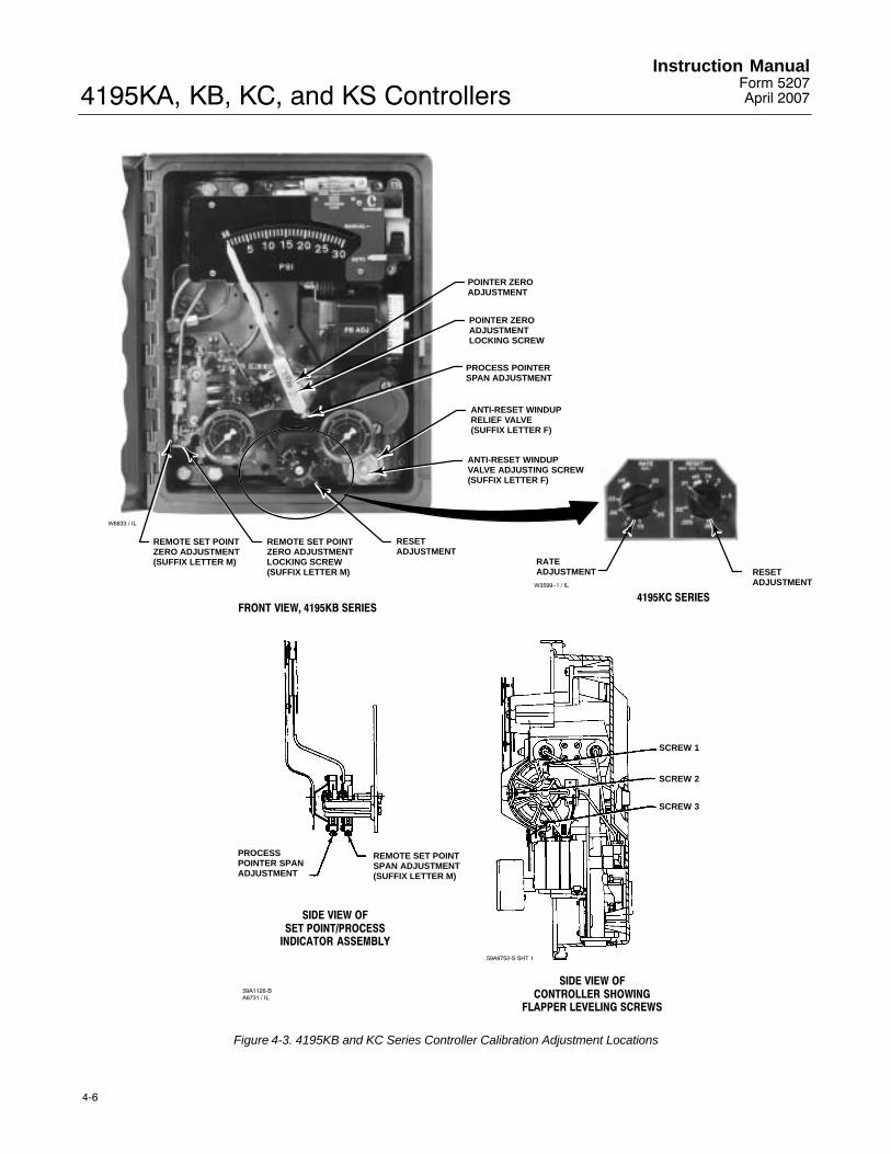
Remote Set Point (suffix letter M) Zeroand Span CalibrationRefer to figures 4-1 and 4-3 for adjustmentlocations. Refer to figure 7-1 for key numberlocations.
Note
Any adjustment of the remote setpoint span adjustment screw requiresreadjustment of the remote set pointzero adjustment screw.
1. Remove the two screws (key 6) and lift off theproportional band indicator cover (key 36).
4195KA, KB, KC, and KS ControllersInstruction Manual
Form 5207April 2007
4-6
RATEADJUSTMENT RESET
ADJUSTMENTW3599−1 / IL
4195KC SERIES
POINTER ZEROADJUSTMENT
POINTER ZEROADJUSTMENTLOCKING SCREW
PROCESS POINTERSPAN ADJUSTMENT
REMOTE SET POINTZERO ADJUSTMENTLOCKING SCREW(SUFFIX LETTER M)
REMOTE SET POINTZERO ADJUSTMENT(SUFFIX LETTER M)
FRONT VIEW, 4195KB SERIES
SCREW 1
SCREW 2
SCREW 3
PROCESSPOINTER SPANADJUSTMENT
REMOTE SET POINTSPAN ADJUSTMENT(SUFFIX LETTER M)
SIDE VIEW OFSET POINT/PROCESS
INDICATOR ASSEMBLY
SIDE VIEW OFCONTROLLER SHOWING
FLAPPER LEVELING SCREWS
39A1126-BA6731 / IL
59A9752-S SHT 1
ANTI-RESET WINDUPRELIEF VALVE(SUFFIX LETTER F)
RESETADJUSTMENT
ANTI-RESET WINDUPVALVE ADJUSTING SCREW(SUFFIX LETTER F)
W6833 / IL
Figure 4-3. 4195KB and KC Series Controller Calibration Adjustment Locations

4195KA, KB, KC, and KS ControllersInstruction ManualForm 5207April 2007
4-7
2. Set the proportional band between DIRECT andREVERSE.
3. Apply remote set point pressure equal to thelower range limit.
4. The set point indicator should indicate theprocess scale lower limit. If not, loosen the remoteset point zero adjustment locking screw and adjustthe remote set point zero adjustment screw until theset point indicator aligns with the process scalelower limit. Tighten the zero adjustment lockingscrew.
5. Apply remote set point pressure equal to theupper range limit.
6. The set point indicator should indicate theprocess scale upper limit. If not, adjust the remoteset point span adjustment screw to correct one-halfthe error as follows: clockwise to increase span for alow indication; counterclockwise to decease span fora high indication.
7. Repeat steps 3 through 6 until the error iseliminated.
8. Adjust the remote set point pressure to themid-range value.
9. Make sure the set point indicator is within ±1percent of the mid-scale mark, and if so, proceed tostep 12. If the set point indicator is not within 1percent, but is within ±2 percent of the mid-scalemark, proceed with step 10. If the set point indicatoris not within ±2 percent, proceed to the remote setpoint zero and span adjustment procedure in theMaintenance section.
10. Loosen the remote set point zero adjustmentlocking screw and adjust the remote set point zeroadjustment screw to correct for half the error at midscale. Tighten the zero adjustment locking screw.
11. Apply remote set point pressure equal to thelower and upper range limits and make sure the setpoint indicator is within ±1 percent.
12. If necessary, perform the process indicator zeroand span calibration procedure in this section.Otherwise, perform the flapper alignment procedurein this section.
Flapper Alignment
Note
Perform the process indicator zeroand span calibration procedure and,for controllers with remote set point(suffix letter M), the remote set point
zero and span calibration procedurebefore the flapper alignment.
Flapper leveling screw numbers and adjustmentsare shown in figure 4-3. Key number locations areshown in figure 7-1.
Provide a means of measuring the controller outputpressure by connecting the controller output to apressure gauge (open-loop conditions must exist).Do not apply supply pressure at this time.
Note
4195KB and KC Series controllers withanti-reset windup (suffix letter F) aresupplied with two O-rings (key 52),valve cover (key 51), and two machinescrews (key 53). Use these parts in thenext step.
1. For controllers with anti-reset windup (suffix letterF), record the direction of the arrow on the anti-resetwindup relief valve (key 55). Remove the relief valveand install the two O-rings (key 52) and valve cover(key 51) supplied with the controller. Secure thevalve cover with the two machine screws (key 53)provided.
2. If necessary, remove the two machine screws(key 6) and lift off the proportional band indicatorcover (key 36).
3. If the controller has the external feedback option(available with the 4195KB Series only), connect thecontroller output to the external feedbackconnection. See figure 2-5 for the location of theoutput and external feedback connections.
4. Provide regulated supply pressure to thecontroller. Do not exceed the normal operatingpressure in table 1-6.
5. For a controller with manual set point, move theset point indicator to the mid-scale mark on theprocess scale. For a controller with remote set point(suffix letter M), adjust the remote set point pressureuntil the set point indicator is at the mid-scale markon the process scale.
6. Set the reset adjustment to 0.01 minutes perrepeat.
7. If the controller has rate (4195KC Series), turnthe rate adjustment to OFF.
8. Apply process pressure equal to the mid-scalevalue of the process scale span. If pressure is notavailable to pressure the input element to mid-scalevalue, an alternate method is to disconnect linknumber 1 at the input element and tape the processpointer at mid-scale mark on the process scale. If

4195KA, KB, KC, and KS ControllersInstruction Manual
Form 5207April 2007
4-8
the controller has a capsular input element, note thehole where link number 1 is connected to the inputelement, then disconnect link 1. This method shouldonly be used if pressure is not available to pressurethe input element to the mid-scale value.
Note
Because of the high controller gain,the controller output will not remainstable in steps 9 through 13. Thecontroller output gauge is adequate tocheck the output pressure during thisprocedure.
9. Set the proportional band between DIRECT andREVERSE.
10. The controller output should be relatively stableat any value within the output range. If not, adjustflapper leveling screw 2 (the screw nearest thenozzle) until the output is relatively stable.
11. Set the proportional band to 30 percentDIRECT. The controller output should be relativelystable at any value within the output range. If not,adjust flapper leveling screw 3 (the screw nearestthe nozzle) until the output is relatively stable.
12. Set the proportional band to 30 percentREVERSE. The controller output should be relativelystable at any value within the output range. If not,adjust flapper leveling screw 1 (the screw nearestthe nozzle) until the output is relatively stable.
13. Repeat steps 9 through 12 until the controlleroutput remains relatively stable without furtherflapper leveling screw adjustment.
Note
Steps 14 through 20 check the flapperalignment.
14. Set the proportional band to 30 percentDIRECT.
W4039 / IL
W4038 / IL
RIGHT-HAND EDGE
LEFT-HAND EDGE
Figure 4-4. Alignment of the Process Pointer with the Set Point Indicator
15. Apply process pressure to the input element or,if link 1 was disconnected, remove the tape from theprocess pointer and move the pointer until it alignswith the right-hand edge of the set point indicator asshown in figure 4-4.
The controller output should be within 0.14 bar (2psig) of the supply pressure.
16. Apply process pressure to the input element or,if disconnected, move the process pointer until italigns with the left-hand edge of the set pointindicator as shown in figure 4-4.
The controller output pressure should go to 0 bar (0psig).
17. Set the proportional band to 30 percentREVERSE.
18. Apply process pressure to the input element or,if disconnected, move the process pointer until italigns with the right-hand edge of the set pointindicator as shown in figure 4-4. The controlleroutput should be 0 bar (0 psig).
19. Apply process pressure to the input element or,if disconnected, move the process pointer until italigns with the left-hand edge of the set pointindicator as shown in figure 4-4. The controlleroutput should be within 0.14 bar (2 psig) of thesupply pressure.
20. If the controller does not perform as indicated insteps 14 through 19, the flapper is not correctly

4195KA, KB, KC, and KS ControllersInstruction ManualForm 5207April 2007
4-9
aligned. This may occur because the output was notsufficiently stabilized in steps 9 through 13. Repeatsteps 8 through 19.
21. When the flapper is correctly aligned, set theproportional band to 400 percent in the desiredcontroller action and replace the proportional bandindicator cover. If link 1 was disconnected,reconnect link 1 to the input element using the samehole noted in step 8.
22. Remove supply pressure.
23. If the controller has the external feedbackoption, disconnect the outside tubing which connectsthe external feedback connection to the outputconnection.
24. For controllers with anti-reset windup (suffixletter F), remove the two machine screws, valvecover and two O-rings installed in step 1 of thisprocedure. Install the anti-reset windup relief valve(key 55) with the arrow pointing in the directionrecorded in step 1.
Anti-Reset Windup (suffix letter F)Differential Relief Valve Calibration
Calibration for the differential relief valve torelieve on rising controller output pressure
1. Provide a means of measuring the controlleroutput pressure by connecting the controller outputto a pressure gauge (open-loop conditions mustexist). Do not apply supply pressure at this time.
2. Set the reset adjustment to 0.01 minutes perrepeat (wide open) and the rate adjustment (4195KCSeries only) to the OFF position.
3. For a controller with manual set point, move theset point indicator to the mid-scale mark on theprocess scale. For a controller with remote set point,adjust the remote set point pressure until the setpoint indicator is at the mid-scale mark on theprocess scale.
4. Set the proportional band to 100 percent in eitherthe DIRECT or REVERSE action depending on theapplication requirements.
5. Refer to figure 4-3 for the location of theanti-reset windup differential relief valve. For thedifferential relief valve to relieve on rising controlleroutput pressure, install the valve so the arrow on thevalve points down. To change the direction of thearrow, loosen the two mounting screws, pull thevalve out, and reinstall the valve with the arrowpointing down. Tighten the two mounting screws.
6. Provide a regulated supply pressure to thecontroller. Do not exceed the normal operatingpressure in table 1-6.
Note
Because of the high controller gainwith the reset adjustment at 0.01minutes per repeat, the controlleroutput will not balance perfectly in thefollowing step. If the controller outputis stable for approximately 5 seconds,it is adequately balanced.
7. Increase the process pressure (or vacuum for avacuum controller) to the controller until thecontroller output pressure balances at 0.4 bar (6psig) for a 0.2 to 1.0 bar (3 to 15 psig) output rangeor 0.8 bar (12 psig) for a 0.4 to 2.0 bar (6 to 30 psig)output range.
8. Turn the reset adjustment to the CLOSED(4195KB Series) or OFF (4195KC Series) position.
9. Increase the controller output pressure in smallsteps [approximately 0.04 bar (0.5 psig)] bychanging the process pressure to the controller or bychanging the controller set point. After each changein process pressure or set point, the controlleroutput pressure should quickly change and thenstabilize at the new value.
10. Continue to change the controller outputpressure in 0.04 bar (0.5 psi) steps and check theoutput pressure after each step to make sure itstabilizes. At some point, the controller output willstart to ramp upward to supply pressure with nofurther change to the controller input or set point.Record the controller output pressure where thisramping action begins because this is the point atwhich the differential relief valve has relieved.
11. To obtain the differential relief valve differentialsetting, calculate the difference between the originalcontroller output pressure in step 7 and thecontroller output pressure recorded in step 10.
12. If the differential pressure calculated in step 11is incorrect for the application, adjust the differentialpressure by turning the differential relief valveadjustment screw shown in figure 4-3. Turn thescrew clockwise to decrease the differentialpressure or counterclockwise to increase thedifferential pressure. The differential relief valve isset at the factory to relieve at approximately 0.4 bar(5 psi) differential pressure.
13. Repeat steps 7 through 12 until the requireddifferential pressure is obtained.

4195KA, KB, KC, and KS ControllersInstruction Manual
Form 5207April 2007
4-10
Calibration for the differential relief valve torelieve on falling controller output pressure
1. Provide a means of measuring the controlleroutput pressure by connecting the controller outputto a pressure gauge (open-loop conditions mustexist). Do not apply supply pressure at this time.
2. Set the reset adjustment to 0.01 minutes perrepeat (wide open) and the rate adjustment (4195KCSeries only) to the OFF position.
3. For a controller with manual set point, move theset point indicator to the mid-scale mark on theprocess scale. For a controller with remote set point,adjust the remote set point pressure until the setpoint indicator is at the mid-scale mark on theprocess scale.
4. Set the proportional band to 100 percent in eitherthe DIRECT or REVERSE action depending on theapplication requirements.
5. Refer to figure 4-3 for the location of theanti-reset windup differential relief valve. For thedifferential relief valve to relieve on falling controlleroutput pressure, install the valve so the arrow on thevalve points up. To change the direction of thearrow, loosen the two mounting screws, pull thevalve out, and reinstall the valve with the arrowpointing up. Tighten the two mounting screws.
6. Provide a regulated supply pressure to thecontroller. Do not exceed the normal operatingpressure in table 1-6.
Note
Because of the high controller gainwith the reset adjustment at 0.01minutes per repeat, the controlleroutput will not balance perfectly in thefollowing step. If the controller outputis stable for approximately 5 seconds,it is adequately balanced.
7. Increase the process pressure (or vacuum for avacuum controller) to the controller until thecontroller output pressure balances at 0.8 bar (12psig) for a 0.2 to 1.0 bar (3 to 15 psig) output rangeor 1.6 bar (24 psig) for a 0.4 to 2.0 bar (6 to 30 psig)output range.
8. Turn the reset adjustment to the CLOSED(4195KB Series) or OFF (4195KC Series) position.
9. Decrease the controller output pressure in smallsteps [approximately 0.04 bar ( 0.5 psig)] bychanging the process pressure to the controller or by
changing the controller set point. After each changein controller process pressure or set point, thecontroller output pressure should quickly change andthen stabilize at the new value.
10. Continue to change the controller outputpressure in 0.04 bar (0.5 psi) steps and check theoutput pressure after each step to make sure itstabilizes. At some point, the controller output willstart to ramp downward to 0 bar (0 psig) with nofurther change to the controller input or set point.Record the controller output pressure where thisramping action begins because this is the point atwhich the differential relief valve has relieved.
11. To obtain the differential relief valve differentialsetting, calculate the difference between the originalcontroller output pressure in step 7 and thecontroller output pressure recorded in step 10.
12. If the differential pressure calculated in step 11is incorrect for the application, adjust the differentialpressure by turning the differential relief valveadjustment screw, shown in figure 4-3. Turn thescrew clockwise to decrease the differentialpressure or counterclockwise to increase thedifferential pressure. The differential relief valve isset at the factory to relieve at approximately 0.4 bar(5 psi) differential pressure.
13. Repeat steps 7 through 12 until the requireddifferential pressure is obtained.
Principle of Operation for 4195KB andKC Series Controllers
Overall OperationRefer to the schematic diagram in figure 4-5 for the4195KB Series controllers, or to the schematicdiagram in figure 4-6 for the 4195KC Seriescontrollers.
The input element is connected to the processpointer and to the flapper by connecting links. As theprocess pressure increases (in a direct-actingcontroller), the flapper moves toward the nozzle,restricting flow through the nozzle and increasingnozzle pressure. When this occurs, relay actionincreases the output pressure (delivery) of thecontroller. Output pressure is fed back to theproportional bellows and to the reset bellows. Theaction of the proportional bellows quicklycounteracts the flapper movement that resulted fromthe process pressure change and backs the flapperaway from the nozzle.
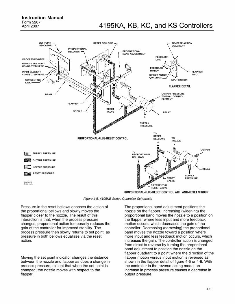
4195KA, KB, KC, and KS ControllersInstruction ManualForm 5207April 2007
4-11
SET POINTINDICATOR
PROCESS POINTER
REMOTE SET POINTCONNECTED HERE
INPUT ELEMENTCONNECTED HERE
CONNECTING LINK
BEAM
FLAPPER
NOZZLE
PROPORTIONALBELLOWS
RESET BELLOWS
PROPORTIONALBAND ADJUSTMENT
SUPPLYPRESSURE
RELAY
OUTPUT PRESSURETO FINAL CONTROLELEMENT
REVERSE ACTIONQUADRANT
FLAPPERPIVOT
FEEDBACKLINK
FEEDBACK MOTION
DIRECT ACTIONQUADRANT
INPUT MOTION
FLAPPER DETAIL
SUPPLY PRESSURE
OUTPUT PRESSURE
NOZZLE PRESSURE
RESET PRESSURE
RELAY
TONOZZLE
TORESETBELLOWS
TOPROPORTIONALBELLOWS
SUPPLYPRESSURERESET
VALVE
DIFFERENTIALRELIEF VALVE
OUTPUT
PROPORTIONAL-PLUS-RESET CONTROL
PROPORTIONAL-PLUS-RESET CONTROL WITH ANTI-RESET WINDUP
46A9764−CB1908−4 / IL
RESETVALVE
Figure 4-5. 4195KB Series Controller Schematic
Pressure in the reset bellows opposes the action ofthe proportional bellows and slowly moves theflapper closer to the nozzle. The result of thisinteraction is that, when the process pressurechanges, proportional action temporarily reduces thegain of the controller for improved stability. Theprocess pressure then slowly returns to set point, aspressure in both bellows equalizes via the resetaction.
Moving the set point indicator changes the distancebetween the nozzle and flapper as does a change inprocess pressure, except that when the set point ischanged, the nozzle moves with respect to theflapper.
The proportional band adjustment positions thenozzle on the flapper. Increasing (widening) theproportional band moves the nozzle to a position onthe flapper where less input and more feedbackmotion occurs, which decreases the gain of thecontroller. Decreasing (narrowing) the proportionalband moves the nozzle toward a position wheremore input and less feedback motion occurs, whichincreases the gain. The controller action is changedfrom direct to reverse by turning the proportionalband adjustment to position the nozzle on theflapper quadrant to a point where the direction of theflapper motion versus input motion is reversed asshown in the flapper detail of figure 4-5 or 4-6. Withthe controller in the reverse-acting mode, anincrease in process pressure causes a decrease inoutput pressure.
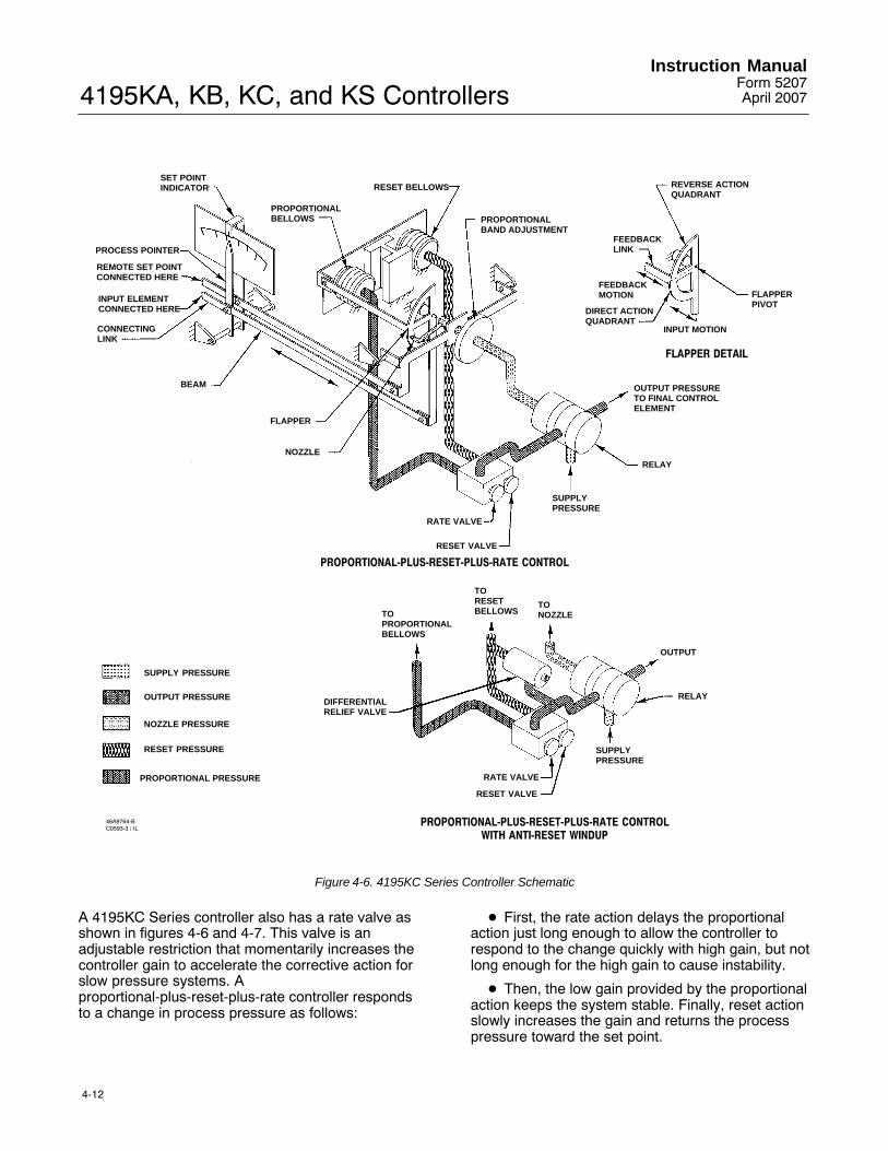
4195KA, KB, KC, and KS ControllersInstruction Manual
Form 5207April 2007
4-12
SET POINTINDICATOR
PROCESS POINTER
REMOTE SET POINTCONNECTED HERE
INPUT ELEMENTCONNECTED HERE
CONNECTING LINK
BEAM
FLAPPER
NOZZLE
PROPORTIONALBELLOWS
RESET BELLOWS
PROPORTIONALBAND ADJUSTMENT
SUPPLYPRESSURE
RELAY
OUTPUT PRESSURETO FINAL CONTROLELEMENT
REVERSE ACTIONQUADRANT
FLAPPERPIVOT
FEEDBACKLINK
FEEDBACK MOTION
DIRECT ACTIONQUADRANT
INPUT MOTION
FLAPPER DETAIL
SUPPLY PRESSURE
OUTPUT PRESSURE
NOZZLE PRESSURE
RESET PRESSURE
RELAY
TONOZZLE
TORESETBELLOWSTO
PROPORTIONALBELLOWS
DIFFERENTIALRELIEF VALVE
SUPPLYPRESSURE
OUTPUT
PROPORTIONAL-PLUS-RESET-PLUS-RATE CONTROL
PROPORTIONAL-PLUS-RESET-PLUS-RATE CONTROLWITH ANTI-RESET WINDUP
46A9764-BC0593-3 / IL
PROPORTIONAL PRESSURE RATE VALVE
RESET VALVE
RATE VALVE
RESET VALVE
Figure 4-6. 4195KC Series Controller Schematic
A 4195KC Series controller also has a rate valve asshown in figures 4-6 and 4-7. This valve is anadjustable restriction that momentarily increases thecontroller gain to accelerate the corrective action forslow pressure systems. Aproportional-plus-reset-plus-rate controller respondsto a change in process pressure as follows:
� First, the rate action delays the proportionalaction just long enough to allow the controller torespond to the change quickly with high gain, but notlong enough for the high gain to cause instability.
� Then, the low gain provided by the proportionalaction keeps the system stable. Finally, reset actionslowly increases the gain and returns the processpressure toward the set point.
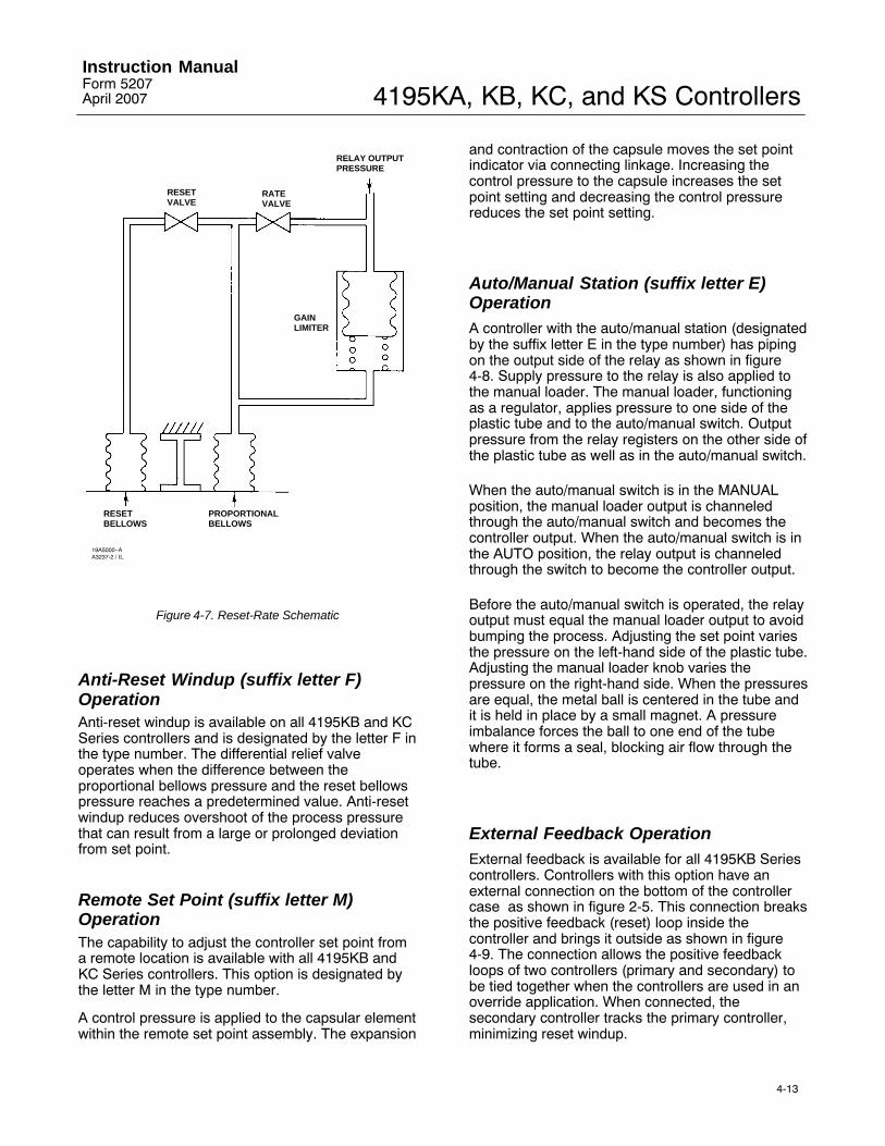
4195KA, KB, KC, and KS ControllersInstruction ManualForm 5207April 2007
4-13
RELAY OUTPUTPRESSURE
RATEVALVE
RESETVALVE
GAINLIMITER
PROPORTIONALBELLOWS
RESETBELLOWS
19A5000−AA3237-2 / IL
Figure 4-7. Reset-Rate Schematic
Anti-Reset Windup (suffix letter F)OperationAnti-reset windup is available on all 4195KB and KCSeries controllers and is designated by the letter F inthe type number. The differential relief valveoperates when the difference between theproportional bellows pressure and the reset bellowspressure reaches a predetermined value. Anti-resetwindup reduces overshoot of the process pressurethat can result from a large or prolonged deviationfrom set point.
Remote Set Point (suffix letter M)OperationThe capability to adjust the controller set point froma remote location is available with all 4195KB andKC Series controllers. This option is designated bythe letter M in the type number.
A control pressure is applied to the capsular elementwithin the remote set point assembly. The expansion
and contraction of the capsule moves the set pointindicator via connecting linkage. Increasing thecontrol pressure to the capsule increases the setpoint setting and decreasing the control pressurereduces the set point setting.
Auto/Manual Station (suffix letter E)OperationA controller with the auto/manual station (designatedby the suffix letter E in the type number) has pipingon the output side of the relay as shown in figure4-8. Supply pressure to the relay is also applied tothe manual loader. The manual loader, functioningas a regulator, applies pressure to one side of theplastic tube and to the auto/manual switch. Outputpressure from the relay registers on the other side ofthe plastic tube as well as in the auto/manual switch.
When the auto/manual switch is in the MANUALposition, the manual loader output is channeledthrough the auto/manual switch and becomes thecontroller output. When the auto/manual switch is inthe AUTO position, the relay output is channeledthrough the switch to become the controller output.
Before the auto/manual switch is operated, the relayoutput must equal the manual loader output to avoidbumping the process. Adjusting the set point variesthe pressure on the left-hand side of the plastic tube.Adjusting the manual loader knob varies thepressure on the right-hand side. When the pressuresare equal, the metal ball is centered in the tube andit is held in place by a small magnet. A pressureimbalance forces the ball to one end of the tubewhere it forms a seal, blocking air flow through thetube.
External Feedback OperationExternal feedback is available for all 4195KB Seriescontrollers. Controllers with this option have anexternal connection on the bottom of the controllercase as shown in figure 2-5. This connection breaksthe positive feedback (reset) loop inside thecontroller and brings it outside as shown in figure4-9. The connection allows the positive feedbackloops of two controllers (primary and secondary) tobe tied together when the controllers are used in anoverride application. When connected, thesecondary controller tracks the primary controller,minimizing reset windup.

4195KA, KB, KC, and KS ControllersInstruction Manual
Form 5207April 2007
4-14
AUTOMATICPOSITION
OUTPUT PRESSURETO FINAL CONTROLELEMENT
SUPPLYPRESSURE
RELAY
AUTO/MANUALSWITCH
MANUAL LOADER
MANUALLOADERKNOB
MANUALPOSITION
AUTO/MANUALSWITCH
OUTPUT PRESSURETO FINAL CONTROLELEMENT
PLASTIC TUBE
METAL BALL
RELAY OUTPUT PRESSURE
SUPPLY PRESSURE
MANUAL LOADER OUTPUT PRESSURE
48A5230-AA2999-1 / IL
Figure 4-8. 4195KB and KC Series Auto/Manual Station Schematic
47A0975−AA3342-1 / IL
TORESETBELLOWS
TONOZZLE
OUTPUT
RELAY
SUPPLYPRESSURE
EXTERNAL FEEDBACK TOOUTPUT OF HIGH OR LOWSELECT RELAY
TOPROPORTIONALBELLOWS
RESETVALVE
SUPPLY PRESSURE
OUTPUT PRESSURE
NOZZLE PRESSURE
RESET PRESSURE
SELECT RELAYOUTPUT
Figure 4-9. Schematic of External Feedback Option

4195KA, KB, KC, and KS ControllersInstruction ManualForm 5207April 2007
5-1
Section 5 4195KS Series Differential GapControllers
Operating InformationThis section includes descriptions of adjustmentsand procedures for prestartup and startup. Locationof adjustments is shown in figures 5-1 and 5-2. Tobetter understand the adjustments and overalloperation of the controller, refer to the Principle ofOperation section and the schematic diagrams,figures 5-4 and 5-5.
Note
Some of the following proceduresrequire that the proportional bandknob be adjusted to between DIRECTand REVERSE. If this is done, it willbe necessary to set the proportionalband knob to 400 (direct or reverseaction) before replacing theproportional band indicator cover.
Adjustments for 4195KS SeriesControllers
Manual Set Point
The set point adjustment adjusts the upper or lowerswitching point, depending on controller action. Toadjust the set point, open the controller cover, andmove the set point adjustment until the pointerindicates the desired value of pressure on theprocess pressure scale. Move the adjustment to theright to increase the set point, and to the left todecrease it. Adjusting the set point does not affectthe differential gap setting.
Remote Set Point (Option M)
CAUTION
Do not move the set point manuallyon controllers with remote set point.Doing so could damage the controller.
If the controller is equipped with remote set pointoption, vary the remote set point pressure to change
the set point. Increase the pressure to increase theset point, and decrease the pressure to decreasethe set point.
Proportional Band (Differential Gap)
The proportional band knob adjusts width of the gapbetween switching points. Rotate the knob until thedesired value is opposite the line on the proportionalband indicator cover.
Changing Controller Action
Controller action can be switched from direct toreverse or vice versa by loosening the screws on theproportional band indicator cover and moving thecover out so the proportional band knob can berotated to the desired action. The white portion ofthe adjustment enables direct controller action; theblack portion enables reverse controller action.
Auto/Manual Switching (Option E)
Refer to figure 5-5 if the controller has theauto/manual option. Two balance methods areavailable to equalize the manual output with thecontroller pressure. To switch from automatic tomanual mode, carefully adjust the loader knob untilthe metal ball inside the plastic tube moves into theswitching zone. The move the automatic/manualswitch to MANUAL. Turn the loader knob clockwiseto increase the controller output or counter clockwiseto decrease it. To switch from manual to automaticmode, adjust the set point manually or with remoteset point pressure to move the ball into the switchingzone. Turn the switch to AUTOMATIC, and adjustthe set point manually or with the remote set pointpressure to control the output.
When the automatic/manual switch is inAUTOMATIC, adjusting the loader knob has noeffect on the controller output. When theautomatic/manual switch is in MANUAL, changingthe set point adjustment has no effect on thecontroller output.
Note
Switching the controller betweenautomatic and manual, or manual andautomatic mode, without balancingthe outputs, can disturb the processand cause controller cycling.

4195KA, KB, KC, and KS ControllersInstruction Manual
Form 5207April 2007
5-2
C0528-1/IL
BOURDON TUBE
PROCESSINDICATORPROCESSINDICATOR
CONNECTINGLINK
SET POINTADJUSTMENT
INDICATOR ZERO ADJUSTMENT
ZERO ADJUSTMENTLOCKING SCREW
PROCESSSPAN ADJUSTMENT
OUTPUT PRESSUREGAUGE
PROPORTIONALBAND INDICATORCOVER
PROPORTIONALBAND ADJUSTMENT
SUPPLY PRESSUREGAUGE
ZERO ADJUSTMENTLOCKING SCREW
INDICATORZEROADJUSTMENT
TIE BAR
LINEARITYADJUSTMENT
PROCESSSPANADJUSTMENT
LINK 5
LINK 1
SHORTPIVOTASSEMBLY
LONG PIVOTASSEMBLY
BI METAL STRIP FOR TEMPERATURE COMPENSATION
SENSING ELEMENT CAN ALSO BE A CAPSULAR ELEMENT FRONT VIEW OF CONTROLLER WITHBOURDON TUBE PROCESS SENSOR
CAPSULAR ELEMENTPROCESS SENSOR
NOTE:
Figure 5-1. 4195KS Series Controller Parts and Adjustments Locations
Prestartup Checks for 4195KS SeriesControllersWhen performing the checks, open loop conditionsmust exist. Refer to figure 5-1 for location ofadjustments.
Note
If the controller has the auto/manualoption (option E), be sure thecontroller is in the automatic modeprior to performing prestartup checks.
1. Connect supply pressure to the supply pressureregulator, and be sure it is delivering the propersupply pressure to the controller. Provide a meansof measuring the controller output pressure.
2. For controllers with remote set point (option M),connect regulated pressure of 0.2 to 1.0 bar (3 to 15psig) or 0.4 to 2.1 bar (6 to 30 psig) to the remoteset point connection at the top of the controller case.
3. Loosen two screws (key 6), lift off theproportional band cover (key 36), and set the
proportional band knob between DIRECT andREVERSE.
4. The process indicator should indicate the processpressure. For example, with the process pressure at50 percent of the input span, the process pointershould be 50 percent (+/-1 percent) of its span.Slight adjustment of the indicator zero screw may benecessary. See figure 5-1 for zero adjustment andlocking screw location.
5. If desired, the accuracy can be verified at otherpoints on the scale. If the indicator appears to be outof calibration, refer to the process zero and spanadjustment portion of the calibration procedure.
6. Install the proportional band cover and install twoscrews (key 6).
Startup for 4195KS Series Controllers
It is recommended that the controller switchingpoints be set as described in the calibrationprocedures.

4195KA, KB, KC, and KS ControllersInstruction ManualForm 5207April 2007
5-3
C0528-1/IL
SCREW 1
SCREW 3
SCREW 2
SIDE VIEW OFCONTROLLER SHOWING
FLAPPER LEVELING SCREWS
PROCESSSPANADJUSTMENT
REMOTE SET POINTSPAN ADJUSTMENT
SIDE VIEW OFSET POINT/PROCESS
INDICATOR ASSEMBLY
Figure 5-1. 4195KS Series Controller Parts and Adjustments Locations (continued)
If they are used, slowly open the upstream anddownstream manual control valves in the pipelineand close the manual bypass valve.
Calibration of 4195KS SeriesControllers
Note
Some of the following proceduresrequire that the proportional bandknob be adjusted to between DIRECTand REVERSE. If this is done, it willbe necessary to set the proportionalband knob to 400 (direct or reverseaction) before replacing theproportional band indicator cover.
If the prestartup checks revealed faulty adjustmentof the process indicator, perform the calibrationprocedures. These procedures are valid for eithershop or field calibration, provided that open processloop conditions exist.
Note
If the controller has the auto/manualoption, be sure the controller is in the
automatic mode prior to performingthe calibration procedures.
Process Zero and Span Adjustment
Note
Any adjustment of the pointer spanadjustment screw will requirereadjustment of the pointer zeroadjustment screw.
1. Refer to figure 5-1 for location of adjustments.
2. Remove the two screws (key 6) and lift off theproportional band indicator cover (key 36).
3. Set the proportional band between DIRECT andREVERSE.
4. Adjust the process pressure to the low limit of theinput range.
5. Adjust the process pointer to the lowest limit ofthe input scale by loosening the zero adjustmentlocking screw and turning the zero adjustmentscrew.
6. Adjust the process pressure to the upper limit ofthe input span. Note whether the pointer indication isabove or below the upper limit of the process scale.
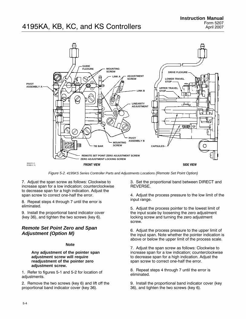
4195KA, KB, KC, and KS ControllersInstruction Manual
Form 5207April 2007
5-4
PIVOTASSEMBLY A
GUIDEFLEXURE MOUNTING
SCREW
LINK A ADJUSTMENTSCREW
LINK B
LINEARITYADJUSTMENT
PIVOTASSEMBLY B
MOUNTINGSCREWTIE BAR
REMOTE SET POINT ZERO ADJUSTMENT SCREWZERO ADJUSTMENT LOCKING SCREW
CAPSULES
UPPER TRAVELSTOP
LOWER TRAVELSTOP
DRIVE FLEXURE
SIDE VIEWFRONT VIEW36A9751-CB1668-4 / IL
Figure 5-2. 4195KS Series Controller Parts and Adjustments Locations (Remote Set Point Option)
7. Adjust the span screw as follows: Clockwise toincrease span for a low indication; counterclockwiseto decrease span for a high indication. Adjust thespan screw to correct one-half the error.
8. Repeat steps 4 through 7 until the error iseliminated.
9. Install the proportional band indicator cover (key 36), and tighten the two screws (key 6).
Remote Set Point Zero and SpanAdjustment (Option M)
Note
Any adjustment of the pointer spanadjustment screw will requirereadjustment of the pointer zeroadjustment screw.
1. Refer to figures 5-1 and 5-2 for location ofadjustments.
2. Remove the two screws (key 6) and lift off theproportional band indicator cover (key 36).
3. Set the proportional band between DIRECT andREVERSE.
4. Adjust the process pressure to the low limit of theinput range.
5. Adjust the process pointer to the lowest limit ofthe input scale by loosening the zero adjustmentlocking screw and turning the zero adjustmentscrew.
6. Adjust the process pressure to the upper limit ofthe input span. Note whether the pointer indication isabove or below the upper limit of the process scale.
7. Adjust the span screw as follows: Clockwise toincrease span for a low indication; counterclockwiseto decrease span for a high indication. Adjust thespan screw to correct one-half the error.
8. Repeat steps 4 through 7 until the error iseliminated.
9. Install the proportional band indicator cover (key36), and tighten the two screws (key 6).

4195KA, KB, KC, and KS ControllersInstruction ManualForm 5207April 2007
5-5
Setting Switching PointsDirect-Acting Controllers
The controller output signal will switch from zeropressure to full supply pressure when increasingprocess pressure passes the upper switching point.
The controller output signal will not return to zeropressure until decreasing process pressure passesthe lower switching point. When making adjustmentsas described in the following steps, keep in mindthat:
� Changing the set point adjustment will moveboth switching points equally in the direction ofadjustment.
� Changing the proportional band adjustment willwiden or narrow the differential gap between the twoswitching points by moving the position of the lowerswitching point.
Figure 5-3 shows the relationship between thepercent of sensor range between switching pointsand the proportional band setting on the controller.The following example illustrates how to use figure5-3.
Example: The sensing element has a range of 30psi. The lower switching point is to be set at 10 psiand the upper switching point is to be set at 25 psi.
Proceed as follows:
� Divide the differential gap (the differencebetween the upper and lower switching points) bythe sensing element range. Multiply the result by100 as shown in the following equation.
Differential Gap
Sensing Element Rangex 100 =
15 psi
30 psix 100 = 50
� Locate the 50 percent line on figure 5-3. Movealong this line until you intersect the curve. Read theproportional band setting on the left hand axis. Forthis example, the setting is approximately 35percent.
1. Using the curve in figure 5-3, determine thecorrect proportional band setting for the desired gap(expressed as a percent of the input span) betweenthe switching points.
2. Set the proportional band knob to the desiredsetting determined in step 1.
A2853−1 / IL
SIDE
% SENSOR RANGE BETWEEN SWITCHING POINTS
PR
OP
OR
TIO
NA
L B
AN
D S
ET
TIN
G
Figure 5-3. Curve for Determining Proportional Band Setting
3. Adjust the set point to the desired upperswitching point.
4. Increase the process pressure until the controlleroutput signal switches from zero pressure to fullsupply pressure.
5. Decrease the process pressure to the desiredswitching point at which the controller output signalswitches from full supply pressure to zero pressure.
6. Narrow or widen the proportional band slowlyuntil the output signal switches from full supplypressure to zero pressure.
7. Repeat steps 4 through 6 until the controlleroutput switches at the desired points.
8. Observe the process pointer when the outputswitches at the upper switching point. The processpointer indication should be within �2 percent of theset point indication.
Reverse-Acting Controllers
The controller output signal will switch from zeropressure to full supply pressure when decreasingprocess pressure passes the lower switching point.
The controller output signal will not return to zeropressure until increasing process pressure passesthe upper switching point. When makingadjustments as described in the following steps,keep in mind that:
� Changing the set point adjustment will moveboth switching points equally in the direction ofadjustment.
� Changing the proportional band adjustment willwiden or narrow the differential gap between the twoswitching points by moving the position of the lowerswitching point.

4195KA, KB, KC, and KS ControllersInstruction Manual
Form 5207April 2007
5-6
SET POINTINDICATOR
PROCESS POINTER
REMOTE SET POINTCONNECTED HERE
INPUT ELEMENTCONNECTED HERE
CONNECTING LINK
FLAPPER
NOZZLE
PROPORTIONALBELLOWS(VENTED)
POSITIVE FEEDBACKBELLOWS
PROPORTIONALBAND ADJUSTMENT
SUPPLYPRESSURE
RELAY
OUTPUT PRESSURETO FINAL CONTROLELEMENT
REVERSE ACTIONQUADRANT
FLAPPERPIVOT
FEEDBACKLINK
FEEDBACK MOTION
DIRECT ACTIONQUADRANT
INPUT MOTION
FLAPPER DETAIL
SUPPLY PRESSURE
OUTPUT PRESSURE
NOZZLE PRESSURE
POSITIVE FEEDBACK PRESSURE
B1546−2 / IL
Figure 5-4. 4195KS Series Controller Schematic
Figure 5-3 shows the relationship between thepercent of sensor range between switching pointsand the proportional band setting on the controller.The following example illustrates how to use figure5-3.
Example: The sensing element has a range of 30psi. The lower switching point is to be set at 10 psiand the upper switching point is to be set at 25 psi.
Proceed as follows:
� Divide the differential gap (the differencebetween the upper and lower switching points) bythe sensing element range. Multiply the result by100 as shown in the following equation.
� Locate the 50 percent line on figure 5-3. Movealong this line until you intersect the curve. Read theproportional band setting on the left hand axis. Forthis example, the setting is approximately 35percent.
Differential Gap
Sensing Element Rangex 100 =
15 psi
30 psix 100 = 50
1. Using the curve in figure 5-3, determine thecorrect proportional band setting for the desired gap(expressed as a percent of the maximum inputelement span) between the switching points.
2. Set the proportional band knob to the desiredsetting determined in step 1.
3. Adjust the set point to the desired lower switchingpoint.
4. Decrease the process pressure until thecontroller output signal switches from zero pressureto full supply pressure.
5. Increase the process pressure to the desiredswitching point at which the controller output signalswitches from full supply pressure to zero pressure.
6. Narrow or widen the proportional band slowlyuntil the output signal switches from full supplypressure to zero pressure.
7. Repeat steps 4 through 6 until the controlleroutput switches at the desired points.
8. Observe the process pointer when the outputswitches at the upper switching point. The processpointer indication should be within +/-2 percent ofthe set point indication.

4195KA, KB, KC, and KS ControllersInstruction ManualForm 5207April 2007
5-7
AUTOMATICPOSITION
OUTPUT PRESSURETO FINAL CONTROLELEMENT
SUPPLYPRESSURE
RELAY
AUTO/MANUALSWITCH
MANUAL LOADER
MANUALLOADERKNOB
MANUALPOSITION
AUTO/MANUALSWITCH
OUTPUT PRESSURETO FINAL CONTROLELEMENT
PLASTIC TUBE
METAL BALL
RELAY OUTPUT PRESSURE
SUPPLY PRESSURE
MANUAL LOADER OUTPUT PRESSURE
48A5230-AA2999-1 / IL
Figure 5-5. 4195KS Series Auto/Manual Schematic
Principle of Operation
Overall OperationRefer to the schematic diagram in figure 5-4.
The input element is connected to the processpointer and to the flapper by connecting links. As theprocess pressure increases (in a direct-actingcontroller). This movement restricts the flow throughthe nozzle and increases nozzle pressure. Whenthis occurs, relay action increases the outputpressure (delivery) of the controller. Output pressureis fed back to the positive feedback bellows. Theaction of this bellows is a positive feedback actionthat moves the flapper closer to the nozzle,increasing nozzle pressure, which in turn, increasesthe relay output. Output pressure to the final controlelement switches to full supply pressure.
As the process pressure decreases, approachingthe lower switching point, the flapper moves awayfrom the nozzle (in a direct-acting controller)reducing nozzle pressure. Through relay action,pressure to the positive feedback bellows is
reduced, moving the flapper further away from thenozzle, and further reducing nozzle pressure. Outputpressure to the final control element switches tozero.
The set point adjustment changes the proximity ofthe nozzle and flapper as does a change in processpressure except that, when the set point is changed,the nozzle moves with respect to the flapper. Theset point adjustment moves both the upper andlower switching points.
The proportional band knob positions the nozzle onthe flapper. Increasing (widening) the proportionalband moves the nozzle away from the inputconnection. When the proportional band adjustmentmoves the nozzle across the feedback connection,the controller action changes between direct andreverse. On a direct-acting controller, changing theproportional band adjustment will widen or narrowthe differential gap between the two switchingpoints. This is accomplished by moving the positionof the lower switching point. On a reverse-actingcontroller, changing the proportional bandadjustment will widen or narrow the differential gap

4195KA, KB, KC, and KS ControllersInstruction Manual
Form 5207April 2007
5-8
between the two switching points by moving theposition of the upper switching point.
Remote Set Point (Option M)
The capability to adjust the controller set point froma remote location is available with all 4195KS Seriescontrollers. This option is designated by the letter Min the type number.
Auto/Manual Option
Controllers with the auto/manual option (designatedby the letter E in the type number) have piping onthe output side of the relay as shown in figure 5-5.Supply pressure to the relay is also applied to themanual loader. The manual loader, functioning as aregulator, applies pressure to one side of the plastic
tube and to the auto/manual switch. Output pressurefrom the relay registers on the other side of theplastic tube as well as in the auto/manual switch.
When the auto/manual switch is in the MANUALposition, the manual loader output is channeledthrough the auto/manual switch and becomes theoutput of the controller. When the auto/manualswitch is in the AUTO position, the relay output ischanneled through the switch to become the outputof the controller.
Before the auto/manual switch is operated, the relayoutput must equal the manual loader output to avoidbumping the process. Adjusting the set point variesthe pressure on the left-hand side of the plastic tube.Adjusting the manual loader knob varies thepressure on the right-hand side. When the pressuresare equal, the metal ball is centered in the tube.Pressure imbalance forces the ball to one end of thetube where it forms a seal, blocking air flow throughthe tube.
4195KA, KB, KC, and KS ControllersInstruction ManualForm 5207April 2007
6-1
Section 6 MaintenanceController parts are subject to normal wear and mustbe inspected and replaced as necessary. Thefrequency of inspection and parts replacementdepends upon the severity of the service conditions.When inspection or repairs are required,disassemble only those parts necessary toaccomplish the job.
Inspection and Maintenance
WARNING
The following maintenanceprocedures require taking thecontroller out of service. To avoidpersonal injury and property damagecaused by uncontrolled processpressure, observe the following beforeperforming any maintenanceprocedures:
Before performing any maintenanceoperations:
� Always wear protective clothing,gloves, and eyewear.
� Provide some temporary meansof control for the process beforetaking the controller out of service.
� Shut off the supply pressure tothe controller.
� Personal injury or propertydamage may result from fire orexplosion if natural gas is used as thesupply pressure medium andpreventative measures are not taken.Preventative measures may include:Remote venting of the unit,Re-evaluation the hazardous areaclassification, ensuring adequateventilation, and the removal of anyignition sources. For information onremote venting of this controller, referto page 2-5.
� Disconnect any operating linesproviding supply air pressure, aprocess input signal, or otherpressure source to the controller.
� Check with your process orsafety engineer for any additional
measures that must be taken toprotect against process media.
Note
Unless otherwise noted, key numbersrefer to figures 7-1 through 7-7.Figures 3-1 and 3-3 show adjustmentlocations for 4195KA Seriescontrollers, figures 4-1 and 4-3 showadjustment locations for 4195KB andKC Series controllers, and figures 5-1and 5-2 show adjustment locations for4195KS Series controllers. Formaintenance on the indicatorassembly, refer to figures 7-2, 7-3 and7-4.
Select the appropriate maintenance procedure andperform the numbered steps. Each procedurerequires that the supply pressure be shut off beforebeginning maintenance.
The maintenance procedures section describes partreplacement common to 4195KA, KB, KC, and KSSeries controllers. After completing the maintenanceprocedures, perform the appropriate calibrationprocedures. Unless otherwise noted, calibrationprocedures for the 4195KA Series controller are inSection 3, calibration procedures for the 4195KBand KC Series controller are in Section 4, andcalibration procedures for the 4195KS Seriescontroller are in Section 5. If difficulty is encounteredperforming the calibration procedures in Section 3,4, or 5 refer to the calibration procedures in thissection.
TroubleshootingAs an aid to troubleshooting, table 6-1 lists somecommon operating faults, their probable cause, andsuggests procedures for correcting the faults.
Replacing Common Controller Parts
WARNING
To avoid personal injury or propertydamage caused by the uncontrolledrelease of pressure, be sure anytrapped process pressure is properlyvented from the controller. Vent anysupply pressure from the controllerbefore disassembly.

4195KA, KB, KC, and KS ControllersInstruction Manual
Form 5207April 2007
6-2
Table 6-1. Troubleshooting Chart Fault Possible Cause Check Correction
1. Process wanders or cyclesabout set point
1.1 Proportional band and resetsettings
1.1 Refer to the startup proceduresfor controller settings
1.1 If stable control cannot beattained, and all other elements ofthe loop are functionally correct,examine other possible causesrelated to the controller
1.2 Supply pressure varying 1.2 Monitor the supply pressurewith an external gauge. Ensure thatit is set correctly and does notfluctuate. Note the number ofinstruments being supplied by theregulator
1.2 Correct as necessary. Oneregulator per instrument isrecommended
1.3 Process pointer rubbing oncover or scale
1.3 Note if the pointer is bent 1.3 Bend pointer to provideclearance
1.4 Input element failure 1.4 Inspect the element for loosescrews and damaged flexures,links or pivots. Using a soapsolution, check the sensingelement for leaks
1.4 Repair or replace parts asnecessary
1.5 Linkage failure 1.5 Check for links that are bent ornot connected properly, flexuresbent or broken, pivots broken
1.5 Replace or repair as necessary
1.6 Relay malfunction 1.6 By changing the process setpoint and observing the outputverify that the output will change atabout the same rate in bothdirections.
1.6 If the output changes quickly inone direction and sluggishly in theother, replace the relay
1.7 Anti-reset windup differentialrelief valve set too low (suffix letterF only)
1.7 The minimum relief valvesetting is dependent on the loopdynamics and the controllersettings. If under normal loadchanges, the relief valve opens,instability can occur. Check byobserving the controller reaction toa set point or load change underclosed loop conditions
1.7 If the differential relief valveappears to be set too low, refer tothe section of this instructionmanual that covers the anti-resetwindup option
2. Controlling off set point asreflected by process and set pointindicators.
Note: Some offset is inherent withproportional-only controllers(4195KA Series). The amount ofoffset is a function of theproportional band setting
2.1 Supply pressure not setcorrectly
2.1 Check with an external source 2.1 Reset the supply pressure ifnecessary. If the condition occursagain, the regulator should berebuilt or replaced
2.2 Flapper not aligned 2.2 Refer to the flapper alignmentprocedure
2.2 Align the flapper as necessary
2.3 Leak in input element/tubingassembly
2.3 Using soap solution, check theinput element and tubing for leaks
2.3 Repair or replace parts asnecessary
2.4 Indicators out of calibration 2.4 Refer to the process indicator(and remote set if applicable) zeroand span calibration procedures inthis manual
2.4 Adjust as necessary
2.5 Linkage not connectedcorrectly
2.5 Inspect for loose screws anddamaged flexures, links or pivots
2.5 Repair or replace parts asnecessary
2.6 Leak in feedback system 2.6 Open the reset valve to 0.1minute/repeat. Adjust outputpressure to 1.4 bar (20 psig). Usingsoap solution, check for leaks inthe proportional and reset bellowsin the tubing that connects thesebellows
2.6 Repair as necessary
(continued)

4195KA, KB, KC, and KS ControllersInstruction ManualForm 5207April 2007
6-3
Table 6-1. Troubleshooting Chart (continued)Fault CorrectionCheckPossible Cause
2. Controlling off set point asreflected by process and set pointindicators.
Note: Some offset is inherent withproportional-only controllers(4195KA Series). The amount ofoffset is a function of theproportional band setting
2.7 Reset valve leaks 2.7 Hold the input constant andadjust the output to 1.0 bar (15psig) for a 0.2 to 1.0 bar (3 to 15psig) output or 2.0 bar (30 psig) fora 0.4 to 2.0 bar (6 to 30 psig)output. Close the reset valve. If thecontroller output varies as the resetvalve is closed and no leaks werefound in the rest of the feedbacksystem (Step 2.6), the reset valveis leaking
2.7 Replace the reset valve(4195KB Series) or the rate/resetvalve (4195KC Series)
2.8 Leak in remote set pointsystem
2.8 Adjust remote set pointpressure to 1.0 bar (15 psig). Usingsoap solution, check for leaks inthe remote set point and tubingassembly
2.8 Repair or replace parts asnecessary
2.9 Input element overpressured 2.9 Check for zero shift 2.9 Replace input element andadjust travel stops of applicable
3. Controlling off set point but notreflected by process and set pointindicators
3.1 Controller is out of calibration 3.1 Refer to the process indicator,remote set point (if applicable), andflapper alignment procedures
3.1 Adjust as necessary
4. No reset action (4195KB and4195KC Series)
4.1 Reset valve is plugged 4.1 Turn the reset valve through itsrange several times to remove anyrestrictions
4.1 If reset action returns, nofurther action is necessary. If not,replace the reset valve (4195KBSeries) or rate/reset valve (4195KCSeries)
4.2 Reset pressure leak 4.2 Adjust the output to 1.0 bar (15psig) for a 0.2 to 1.0 bar (3 to 15psig) output or 2.0 bar (30 psig) fora 0.4 to 2.0 bar (6 to 30 psig)output. Close the reset valve. If theoutput varies and no leaks werefound in the rest of the feedbacksystem (see Step 2.6), the resetvalve is leaking
4.2 Replace the reset valve(4195KB Series) or the rate/resetvalve (4195KC Series)
4.3 Tubing leak 4.3 With reset valve positioned at.01 minute/repeat put 1.0 bar (15psig) to the output port. Using soapsolution, check for leaks in thereset bellows and attached tubingassembly
4.3 Repair or replace parts asnecessary
5. Abnormal control point shiftwhen proportional band is changedNote: Control point shift is inherentwhen changing proportional band inproportional-only controllers(4195KA Series).
5.1 Flapper is out of alignment 5.1 Refer to flapper alignmentprocedure
5.1 Align flapper as necessary
5.2 Flapper is dirty or pitted 5.2 Inspect the flapper 5.2 Clean, or replace flapper asnecessary
6. Controller will not attain fulloutput range
6.1 Output pressure gauge notfunctioning
6.1 Measure the output with anexternal pressure gauge
6.1 Replace the gauge if it isdefective
6.2 Supply pressure not correct 6.2 Check with an external source 6.2 Repair or replace the supplypressure regulator, if necessary.Replace the supply pressure gaugeif necessary
6.3 Proportional band setting toowide (4195KA Series only)
6.3 Adjust proportional bandsetting to 10. Manually cap thenozzle. Output should increase
6.3 Use a narrower proportionalband setting
6.4 Input element or linkage failure 6.4 Inspect the element foralignment and loose screws
6.4 Repair or replace parts asnecessary
(continued)
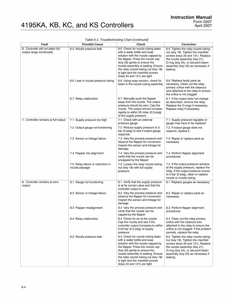
4195KA, KB, KC, and KS ControllersInstruction Manual
Form 5207April 2007
6-4
Table 6-1. Troubleshooting Chart (continued)Fault CorrectionCheckPossible Cause
6. Controller will not attain fulloutput range (continued)
6.5 Nozzle pressure leak 6.5 Check for nozzle tubing leakswith a water bottle and soapsolution with the nozzle capped bythe flapper. Press the nozzle cap(key 23) gently to ensure thenozzle assembly is sealing. Ensurethe relay nozzle tubing nut (key 18)is tight and the manifold screws(keys 34 and 131) are tight
6.5 Tighten the relay nozzle tubingnut (key 18). Tighten the manifoldscrews (keys 34 and 131). Replacethe nozzle assembly (key 21),O-ring (key 24), or set point beamassembly (key 23) as necessary ifleaking
6.6 Leak in nozzle pressure tubing 6.6 Using soap solution, check forleaks in the nozzle tubing assembly
6.6 Replace faulty parts asnecessary. Clean out the relayprimary orifice with the cleanoutwire attached to the relay to ensurethe orifice is not clogged
6.7 Relay malfunction 6.7 Manually push the flapperaway from the nozzle. The outputpressure should be zero. Cap thenozzle. The output should increaserapidly to within 35 mbar (0.5 psig)of the supply pressure
6.7 If the output does not changeas described, remove the relay.Replace the O-rings if necessary.Replace relay if necessary
7. Controller remains at full output 7.1 Supply pressure too high 7.1 Check with an externalpressure gauge
7.1 Supply pressure regulator orgauge may have to be replaced
7.2 Output gauge not functioning 7.2 Reduce supply pressure to 0bar (0 psig) to see if output gaugeresponds
7.2 If output gauge does notrespond, replace it
7.3 Sensor or linkage failure 7.3 Vary the process pressure andobserve the flapper for movement.Inspect the sensor and linkage fordamage
7.3 Repair or replace parts asnecessary
7.4 Flapper mis-alignment 7.4 Vary the process pressure andverify that the nozzle can beuncapped by the flapper
7.4 Perform flapper alignmentprocedures
7.5 Relay failure or restriction innozzle passage
7.5 Loosen the relay nozzle tubingnut (key 18) with full supplypressure
7.5 If the output pressure remainsat the supply pressure, replace therelay. If the output pressure movesto 0 bar (0 psig), clean or replacenozzle or nozzle tubing.
8. Controller remains at zerooutput
8.1 Gauge not functioning 8.1 Verify that the supply pressureis at its correct value and that thecontroller output is zero
8.1 Replace gauges as necessary
8.2 Sensor or linkage failure 8.2 Vary the process pressure andobserve the flapper for movement.Inspect the sensor and linkage fordamage
8.2 Repair or replace parts asnecessary
8.3 Flapper misalignment 8.3 Vary the process pressure andverify that the nozzle can becapped by the flapper
8.3 Perform flapper alignmentprocedures
8.4 Relay malfunction 8.4 Check for air at the nozzle.Cap the nozzle and see if thecontroller output increases to within0.03 bar (0.5 psig) of supplypressure
8.4 Clean out the relay primaryorifice with the cleanout wireattached to the relay to ensure theorifice is not clogged. If the problempersists, replace the relay
8.5 Nozzle pressure leak 8.5 Check for nozzle tubing leakswith a water bottle and soapsolution with the nozzle capped bythe flapper. Press the nozzle cap(key 23) gently to ensure thenozzle assembly is sealing. Ensurethe relay nozzle tubing nut (key 18)is tight and the manifold screws(keys 34 and 131) are tight
8.5 Tighten the relay nozzle tubingnut (key 18). Tighten the manifoldscrews (keys 34 and 131). Replacethe nozzle assembly (key 21),O-ring (key 24), or set point beamassembly (key 23) as necessary ifleaking

4195KA, KB, KC, and KS ControllersInstruction ManualForm 5207April 2007
6-5
DEFLECT LOWER PORTION OF THE SLOT
AND LIFT THE SCALE UP AND OFF
W3440 / IL
W3492 / IL
Figure 6-1. Changing the Scale
Replacing the Process Pressure Scale
WARNING
Refer to the Maintenance WARNINGon page 6-1.
CAUTION
To prevent the pointer or set pointindicator from rubbing on the cover orscale and producing an inaccurateindication, take care not to bend theprocess pointer or the set pointindicator while performing thefollowing procedure.
Refer to figure 6-1.
CLEAN-OUTWIRE
RELAYTAB
EXHAUST PORT(NO O-RINGUSED)
O-RINGS(KEY 15)
RELAYMOUNTINGSCREWS(KEY 10)
W5744 / IL
O-RING(KEY 13)
Figure 6-2. Relay Construction
1. Adjust the set point indicator (either manually orwith the remote set point pressure) to the mid-scalemark on the process scale.
2. Remove the four self-tapping screws (key 37).
3. Slide the process scale (key 61) downward sothat the top of the slot touches the set pointindicator. Deflect the lower portion of the slotoutward and carefully slide the scale up and off,clearing the set point indicator as shown in figure 6-1.
4. To install the replacement scale, deflect the lowerpart of the slot slightly so that the scale slidesdownward over the set point indicator and under theprocess pointer.
5. Secure the scale with the four self-tappingscrews (key 37).
6. If the controller has remote set point (suffix letterM), perform the appropriate remote set point zeroand span calibration procedure in Section 3, 4, or 5.
7. Perform the appropriate process indicator zeroand span calibration and the flapper alignmentprocedures in Section 3, 4, or 5.

4195KA, KB, KC, and KS ControllersInstruction Manual
Form 5207April 2007
6-6
Replacing the Relay
WARNING
Refer to the Maintenance WARNINGon page 6-1.
1. Loosen the two captive screws that hold the relay(key 50) in place.
2. Tip the relay slightly toward the side of the caseto clear the output pressure gauge (key 46) and liftout the relay.
3. Make sure the replacement relay has threeO-rings (keys 13 and 15) installed as shown in figure6-2. The fourth port is for exhaust and does notrequire an O-ring.
4. Install the replacement relay, making sure the tabon the relay, shown in figure 6-2, aligns with the tabon the frame.
5. Tighten the two screws that hold the relay inplace.
6. Perform the appropriate flapper alignmentprocedure in Section 3, 4, or 5.
Replacing the Case and Cover
WARNING
Refer to the Maintenance WARNINGon page 6-1.
CAUTION
The case and cover are an integralunit; attempting to separate them willdamage the hinge. If the cover needsto be replaced, replace the case also.
1. Remove the external piping and fittings from thecontroller.
2. Remove the controller from its mounting to amaintenance area.
3. Remove the nine screws (key 38) from the caseand cover assembly (key 1) and lift out the controllerassembly. If the controller has remote set point(suffix letter M), use a screwdriver or appropriatetool to deflect the case slightly at the remote setpoint connection to remove the controller assembly.Inspect the O-rings around the external pipingconnections and replace as necessary.
4. Position the controller assembly in thereplacement case and cover.
5. Start the nine mounting screws, but do nottighten.
6. Slide the controller assembly down to assure anO-ring seal at the pressure connections along thebottom of the case. Hold the controller assembly inplace while tightening the nine mounting screws.
7. Remove the blow-out plug (key 72) from theoriginal case, and install it in the replacement case.
8. Perform the controller calibration procedures and,if necessary, the appropriate remote set pointcalibration procedure in Section 3, 4, or 5.
9. Mount the controller as described in theInstallation section.
10. Connect the external piping to the controller.
Replacing the Gauges
WARNING
Refer to the Maintenance WARNINGon page 6-1.
CAUTION
Before performing this procedure, besure the replacement gauges are thecorrect range so that they are notdamaged by overpressure.
1. Unscrew the output pressure gauge or the supplypressure gauge (key 46) from the frame (key 3).
2. Before installing the replacement gauge, coat thethreads on the gauge with a sealant such as key 311or equivalent.
3. Screw the replacement gauge into the frame.
4. Apply the correct supply pressure and check forleaks with the nozzle capped for full output pressure.

4195KA, KB, KC, and KS ControllersInstruction ManualForm 5207April 2007
6-7
Replacing the Supply Gauge,Proportional, Reset, Reset Valve, andPositive Feedback Tubing Assemblies
WARNING
Refer to the Maintenance WARNINGon page 6-1.
1. Remove the controller assembly from the caseby performing steps 1 through 3 of the case andcover replacement procedure.
2. Unscrew the nuts at each end of the tubingassembly. Remove the tubing assembly.
3. Install the replacement tubing assembly.
4. Set the reset adjustment to 0.01 (4195KB andKC Series) and set the rate adjustment to OFF(4195KC Series).
5. Apply the correct supply pressure and check forleaks with the nozzle capped for full output pressure.Then, remove the supply pressure.
6. Position the controller assembly in the case andstart, but do not tighten the nine mounting screws.Slide the controller assembly down to assure anO-ring seal at the pressure connections along thebottom of the case. Hold the controller assembly inplace while tightening the nine mounting screws.
7. Perform the controller calibration procedures and,if necessary, the appropriate remote set pointcalibration procedure in Section 3, 4, or 5.
8. Mount the controller as described in theInstallation section.
9. Connect the external piping to the controller.
Replacing the Proportional BandAdjustment Knob, Nozzle Assembly, andSet Point Beam Assembly
WARNING
Refer to the Maintenance WARNINGon page 6-1.
Figure 6-3 shows the parts locations for theproportional band adjustment and set point beam.Unless otherwise noted, refer to this figure whileperforming the following procedures.
Disassembly
1. Remove the controller assembly from the caseby performing steps 1 through 3 of the case andcover replacement procedure.
2. Remove the two machine screws (key 6) and liftoff the proportional band indicator cover (key 36).See figure 7-1 for parts location.
3. Disconnect link 3 from the set point beam shoe,part of the set point beam assembly (key 23).
4. Remove the set point beam bias spring (key 28).
5. Remove the screw and washer (keys 19 and 20)that hold the adjustable set point pivot assembly(key 17) to the frame and remove the pivotassembly.
6. Unscrew the nut that secures the relay nozzletubing assembly (key 18) to the frame manifold (key 135).
7. While holding the proportional band adjustmentknob, remove the screw and washer (keys 19 and 20) that hold the relay nozzle tubing assembly(key 18) to the frame.
8. Remove the proportional band adjustment knob,relay nozzle tubing assembly, and set point beamassembly from the controller.
9. Remove the relay nozzle tubing assembly (key 18) from the set point beam assembly (key 23).
10. Remove the E-ring (key 27) from the nozzleassembly (key 21).
11. Remove the nozzle assembly (key 21) andplastic washer (key 22) from the bottom of the setpoint beam assembly (key 23).
12. Remove the retaining clip (key 26).
13. Remove the proportional band adjustment knob(key 25) and plastic washer from the set point beamassembly (key 23).
14. Inspect the nozzle assembly (key 21) and, ifnecessary, replace it. Inspect the nozzle orifice and,if necessary, clean it. Also, inspect the plasticwashers and, if necessary, replace them.
15. Inspect the nozzle assembly O-ring (key 24)and, if necessary, replace it.
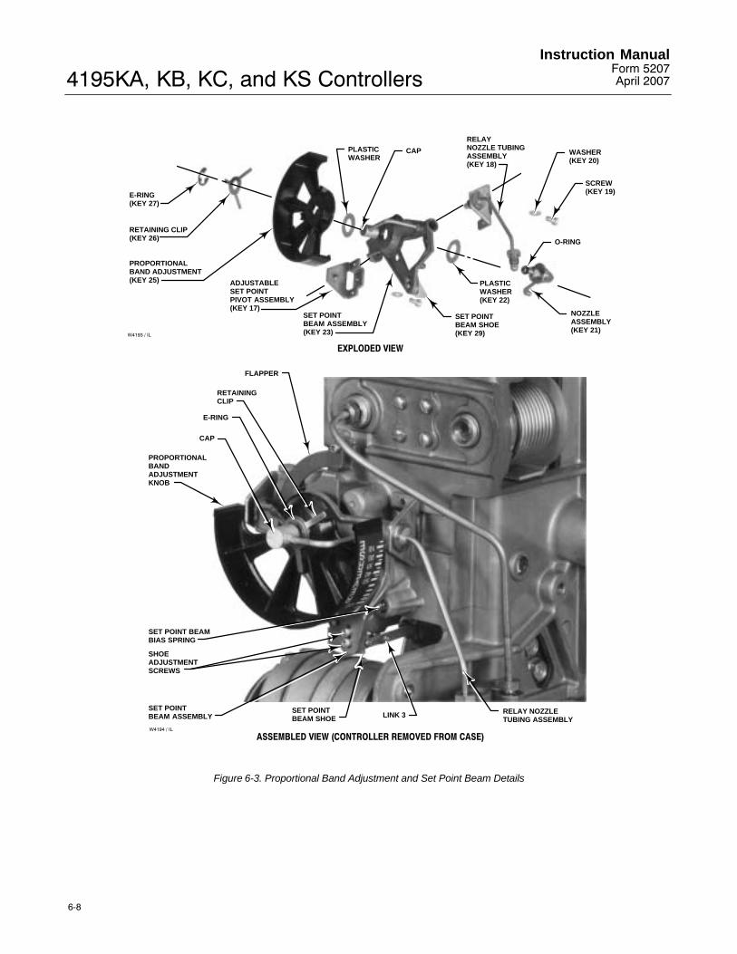
4195KA, KB, KC, and KS ControllersInstruction Manual
Form 5207April 2007
6-8
E-RING(KEY 27)
RETAINING CLIP(KEY 26)
PROPORTIONALBAND ADJUSTMENT(KEY 25) ADJUSTABLE
SET POINTPIVOT ASSEMBLY(KEY 17)
SET POINTBEAM ASSEMBLY(KEY 23)
SET POINTBEAM SHOE(KEY 29)
PLASTICWASHER(KEY 22)
NOZZLEASSEMBLY(KEY 21)
O-RING
SCREW(KEY 19)
WASHER(KEY 20)
RELAY NOZZLE TUBINGASSEMBLY(KEY 18)
CAPPLASTICWASHER
EXPLODED VIEW
ASSEMBLED VIEW (CONTROLLER REMOVED FROM CASE)
FLAPPER
RETAININGCLIP
E-RING
CAP
PROPORTIONALBANDADJUSTMENTKNOB
SET POINT BEAMBIAS SPRING
SHOEADJUSTMENTSCREWS
SET POINTBEAM ASSEMBLY
SET POINTBEAM SHOE LINK 3 RELAY NOZZLE
TUBING ASSEMBLYW4194 / IL
W4193 / IL
Figure 6-3. Proportional Band Adjustment and Set Point Beam Details

4195KA, KB, KC, and KS ControllersInstruction ManualForm 5207April 2007
6-9
Assembly
1. Apply a suitable lubricant, such as key 318 orequivalent, to the set point beam assembly; thenposition a plastic washer (key 22) and theproportional band adjustment knob (key 25) on theset point beam assembly (key 23) as shown in figure 6-3.
2. Position the retaining clip (key 26) on the threeposts on the proportional band adjustment knob.
3. Place the second plastic washer on the nozzleassembly. Apply a suitable lubricant, such as key317 or equivalent, to the nozzle assembly O-ring.
4. Insert the nozzle assembly (key 21) through theset point beam assembly (key 23), the plasticwasher (key 22), the proportional band adjustmentknob (key 25), and the retaining clip (key 26) into thecap. Align the nozzle with the tab on the proportionalband adjustment knob shown in figure 6-4; makesure the proportional band adjustment knob engagesthe flats on the nozzle assembly.
5. While holding the nozzle assembly (key 21)against the set point beam assembly (key 23),depress the retaining clip (key 26), and install theE-ring (key 27) into the E-ring groove on the nozzleassembly (key 21). Ensure that all three tabs of theE-ring are engaged.
6. Inspect the O-ring on the relay nozzle tubingassembly (key 18) and, if necessary, replace it.Apply a suitable lubricant to the O-ring.
7. Install the relay nozzle tubing assembly (key 18)into the set point beam assembly.
8. Set the proportional band adjustment betweenDIRECT and REVERSE. Do this by aligning the tabon the proportional band adjustment knob with thehole in the set point beam assembly as shown infigure 6-4.
9. Position the proportional band adjustment knob,relay nozzle tubing assembly, and the set pointbeam assembly on the frame. Screw the relaynozzle tubing nut loosely into the frame manifold.
10. Insert the machine screw, with plain washer(keys 19 and 20), through the frame and start it intothe relay nozzle tubing assembly (key 18), but donot tighten.
W3761 / IL
TAB
HOLE
Figure 6-4. Proportional Band Adjustment Knob Setting
11. Center the nozzle on the flapper as shown infigure 6-5 while squeezing the set point beamassembly firmly against the relay nozzle tubingassembly. With the nozzle centered on the flapper,tighten the machine screw (key 19). Ensure that thenozzle is still centered on the flapper.
12. Insert the pivot of the adjustable set point pivotassembly (key 17) into the hole in the set pointbeam assembly (key 23).
13. Insert the screw, with washer (keys 19 and 20),through the frame (key 3) and start it into theadjustable set point pivot assembly (key 17), but donot tighten.
14. Squeeze the adjustable set point pivot assemblyagainst the set point beam assembly. Check to besure the nozzle is still centered on the flapper andtighten the machine screw (key 19). If necessary,loosen both machine screws (key 19) to allowslightly moving the adjustable set point pivotassembly, set point beam assembly and the relaynozzle tubing assembly as a unit to center thenozzle on the flapper. After centering the nozzle,tighten the two machine screws.

4195KA, KB, KC, and KS ControllersInstruction Manual
Form 5207April 2007
6-10
FLAPPER NOZZLE
W3449 / IL
Figure 6-5. Nozzle-Flapper Positioning
15. Turn the proportional band adjustment knob to 5percent DIRECT. Refer to figure 6-6 to locate thelocking nut on the adjustable set point pivotassembly. Loosen the locking nut and back out theset screw slightly so that the set point beamassembly falls under its own weight when pivotedupward. Also, maintain a minimum side playbetween the adjustable set point pivot assembly andthe nozzle tubing assembly. Tighten the locking nut.
16. At the frame manifold (key 135), tighten the nutthat secures the tubing from the relay nozzle tubingassembly (key 18). Apply full supply pressure withthe nozzle capped and check for leaks. Removesupply pressure.
17. Install the set point beam bias spring (key 28)into the frame bore and onto the spring seat on theset point beam assembly.
18. Attach link 3 to the set point beam shoe asshown in figure 6-3.
19. For controllers with reset or rate adjustment(4195KB or 4195KC Series), turn the resetadjustment to the CLOSED (4195KB) or OFF(4195KC) position. Set the rate adjustment to theOFF position.
W4195 / IL
LOCKINGNUT
ADJUSTABLE SET POINTPIVOT ASSEMBLY
SCREW AND WASHER(KEYS 19 AND 20)
SCREW AND WASHER(KEYS 19 AND 20)
2
1
NOTES:SCREW INSERTED INTO THE ADJUSTABLE SET POINT PIVOT ASSEMBLY.SCREW INSERTED INTO THE RELAY NOZZLE TUBING ASSEMBLY.
2
1
Figure 6-6. Adjustable Set Point Pivot AssemblyLocking Nut Location
The controller output must be 0 bar (0 psig). To besure the controller output is 0 bar (0 psig ), removesupply pressure, set the reset adjustment to 0.01minutes per repeat and wait 30 seconds; then, turnthe reset adjustment to the CLOSED position(4195KB) or to the OFF position (4195KC).
20. Apply the correct supply pressure (refer to table1-6) to the controller and provide an accurate meansof measuring the controller output pressure.
21. Perform the appropriate process indicator zeroand span calibration procedure and, if necessary,the remote set point zero and span calibrationprocedure in Section 3, 4, or 5. When calibration iscomplete, continue with step 22 below.
Note
The following procedure (steps 22through 28) matches the processpointer motion to the set pointindicator motion so the controller willcontrol at set point at all positions onthe process scale.
22. Set the proportional band to 40 percent inREVERSE or DIRECT depending on the desiredcontroller action.
23. Adjust the set point to the lower limit on theprocess scale.

4195KA, KB, KC, and KS ControllersInstruction ManualForm 5207April 2007
6-11
24. Disconnect link 1 from the input element, notingthe hole from which it is removed, for capsular inputelements, and tape the process pointer to the lowerlimit on the process scale. The output pressure maybe anywhere between 0.2 to 1.0 bar (3 to 15 psig)for a 0.2 to 1.0 bar (3 to 15 psig) output signal rangeor between 0.4 to 2.0 bar (6 to 30 psig) for a 0.4 to2.0 bar (6 to 30 psig) output signal range. If theoutput is not within the specified range, adjust theflapper leveling screw nearest the nozzle until theoutput is within the range specified. Record thecontroller output pressure.
25. Adjust the set point to the upper limit on theprocess scale.
26. Remove the tape and move the process pointeruntil the controller output equals the pressurerecorded in step 24. Note the process pressureindication.
27. The process pressure indication should bewithin ±2 percent of the upper limit on the processscale.
If the process pressure indication in step 26 isgreater than the upper limit of the process scale by 2percent, loosen the shoe adjustment screws (key30), shown in figure 6-3, and move the set pointbeam shoe (key 29) slightly away from the center ofthe flapper assembly.
If the process pressure indication in step 26 is lessthan the upper limit of the process scale by 2percent, loosen the shoe adjustment screws (key30), shown in figure 6-3, and move the set pointbeam shoe (key 29) slightly toward the center of theflapper assembly.
28. Repeat steps 23 through 27 until the error isless than 2 percent of process scale span at theupper limit of the process scale.
29. Remove the tape from the process pointer andreconnect link 1 to the input element. If the controllerhas a capsular input element, be sure to reconnectlink 1 in the same hole noted in step 24.
30. Position the controller assembly in the case andstart, but do not tighten the nine mounting screws.Slide the controller assembly down to assure anO-ring seal at the pressure connections along thebottom of the case. Hold the controller assembly inplace while tightening the nine mounting screws.
31. Perform the controller calibration proceduresand, if necessary, the appropriate remote set pointcalibration procedure in Section 3, 4, or 5.
32. Mount the controller as described in theInstallation section.
33. Connect the external piping to the controller.
Replacing the Flapper Assembly andFlapper Flexure Pivot Assembly
WARNING
Refer to the Maintenance WARNINGon page 6-1.
1. Remove the controller assembly from the caseby performing steps 1 through 3 of the case andcover replacement procedure.
2. Remove the two screws (key 6) and lift off theproportional band indicator cover (key 36).
3. Disconnect link 3 from the set point beam shoe,part of the set point beam assembly (key 23). Referto figure 6-3 for the link location.
4. Remove the set point beam bias spring (key 28).Refer to figure 6-3 for the spring location.
5. Remove the screw and washer (keys 19 and 20)that hold the adjustable set point pivot assembly(key 17) to the frame.
6. Remove the adjustable set point pivot assembly(key 17).
7. Unscrew the nut that secures the relay nozzletubing assembly (key 18) to the frame manifold (key135). Refer to figure 6-3.
8. While holding the proportional band adjustmentknob, remove the screw and washer (keys 19 and 20) that hold the relay nozzle tubing assembly(key 18) to the frame.
9. Remove the proportional band adjustment knob,relay nozzle tubing assembly, and the set pointbeam assembly from the controller.
10. Disconnect link 2 from the flapper assembly(key 11). Refer to figure 6-7 for the link location.
11. Disconnect link 4 from the bellows bracket (key 31). Refer to figure 6-7 for the link location.
12. Remove the two cap screws (key 12) from theflexure pivot assembly (key 9). See figure 6-8 forscrew location.

4195KA, KB, KC, and KS ControllersInstruction Manual
Form 5207April 2007
6-12
PROPORTIONALBELLOWS
BELLOWSBRACKET(KEY 31)
ADJUSTABLESET POINT PIVOTASSEMBLY (KEY 17)
SCREW ANDWASHER(KEYS 19 AND 20)
LINK 4
LINK 2W4199 / IL
Figure 6-7. Bellows Assembly and Proportional Band Adjustment(Process Scale and Proportional Band Indicator Cover Removed)
13. Remove the flapper assembly and link 4 asshown in figure 6-9.
14. Remove the four machine screws (key 10),shown in figure 6-9, that hold the flexure pivotassembly to the frame.
15. Remove the flexure pivot assembly (key 9).
16. Install the replacement flexure pivot assemblywith the four screws (key 10). Do not tighten thescrews.
17. With the controller in the upright position, movethe flexure pivot assembly down as far as possibleand tighten the four screws (key 10).
18. Place the flapper assembly (key 11) on theflexure pivot assembly (key 9) with link 4 through thehole in the frame.
W4770 / IL
FLAPPER LEVELINGSCREW NUMBER 2
FLAPPERASSEMBLY
OBLONG HOLEIN FRAME
FLEXURE PIVOTASSEMBLY SCREWS (KEY 12)
Figure 6-8. Leveling Screw Alignment

4195KA, KB, KC, and KS ControllersInstruction ManualForm 5207April 2007
6-13
FOUR SCREWS(KEY 10)
FLEXURE PIVOTASSEMBLY(KEY 9)
FLAPPERASSEMBLYAND LINK 4
W4198 / IL
Figure 6-9. Exploded View of Flexure Pivot Assembly
19. Position the flapper assembly (key 11) on theflexure pivot assembly (key 9) and start the capscrews (key 12) that hold the flapper assembly tothe flexure pivot assembly. Do not tighten thescrews.
20. Align flapper leveling screw number 2 with thecenterline of the oblong hole in the frame as shownin figure 6-8. Tighten the cap screws (key 12).
Note
The following procedure (steps 21through 23) adjusts link 2 to ensurethat it will always be in tension toeliminate possible instability due tolost motion.
21. Disconnect link 1 from the input element, notingthe hole location if the controller has a capsular inputelement, and manually position the process pointerto the process scale upper limit. Tape the pointer inthis position.
22. Adjust the length of link 2 by turning theadjustment screw, shown in figure 6-10, clockwise toincrease the length or counterclockwise to
W3442-1 / IL
LINK 4 ADJUSTMENTLINK 4
LINK 3LINK 2
LINK 2 ADJUSTMENT
Figure 6-10. Link 2 and 4 Adjustment Locations
decrease the length, so that the pin on the end ofthe link is approximately one-half of its diametershort of aligning with the hole in the flapperassembly, as shown in figure 6-11.
23. Connect link 2 to the flapper assembly.24. Set the proportional band between DIRECT andREVERSE. Do this by aligning the tab on theproportional band adjustment knob with the hole inthe set point beam assembly as shown in figure 6-4.25. Position the proportional band adjustment knob,nozzle assembly, and set point beam assembly, andnozzle tubing assembly on the frame, and screw therelay nozzle tubing assembly nut loosely into theframe manifold (key 135).26. Insert the machine screw, with washer (keys 19and 20), through the frame and start it into the relaynozzle tubing assembly (key 18), but do not tighten.27. Center the nozzle on the flapper as shown infigure 6-5 while squeezing the set point beamassembly firmly against the relay nozzle tubingassembly. With the nozzle centered on the flapper,tighten the machine screw (key 19). Ensure that thenozzle is still centered on the flapper.

4195KA, KB, KC, and KS ControllersInstruction Manual
Form 5207April 2007
6-14
LEVELINGSCREWNUMBER 1
1/2 OF PINDIAMETER
CONNECTING TAB ONFLAPPER ASSEMBLY
W3451 / ILW4191 / IL
Figure 6-11. Link 2 Adjustment
28. Insert the pivot of the adjustable set point pivotassembly (key 17) into the hole in the set pointbeam assembly (key 23).
29. Insert the screw, with washer (keys 19 and 20),through the frame (key 3) and start it into theadjustable set point pivot assembly (key 17), but donot tighten.
30. Squeeze the adjustable set point pivot assemblyagainst the set point beam assembly. Check to besure the nozzle is still centered on the flapper andtighten the machine screw (key 19). If necessary,loosen both machine screws (key 19) to allowslightly moving the adjustable set point pivotassembly, set point beam assembly and the relaynozzle tubing assembly as a unit to center thenozzle on the flapper. After centering the nozzle,tighten the two machine screws.
31. Turn the proportional band adjustment knob to 5percent DIRECT. Refer to figure 6-6 to locate thelocking nut on the adjustable set point pivotassembly. Loosen the locking nut and back out theset screw slightly so that the set point beamassembly falls under its own weight when pivotedupward. Also, maintain a minimum side playbetween the adjustable set point pivot assembly andthe nozzle tubing assembly. Tighten the locking nut.
32. At the frame manifold (key 135), tighten the nutthat secures the tubing from the relay nozzle tubingassembly (key 18). Apply full supply pressure withthe nozzle capped (to obtain maximum outputpressure) and check for leaks. Remove supplypressure.
33. Install the set point beam bias spring (key 28)into the frame bore and onto the spring seat on theset point beam assembly, as shown in figure 6-3.
34. Attach link 3 to the set point beam shoe asshown in figure 6-3.
Note
The following procedure (steps 35through 41) adjusts link 4 so it willalways be in compression to eliminatepossible instability due to lost motion.
35. For controllers with reset and rate adjustments(4195KB or 4195KC Series), remove the supplypressure; then turn the reset adjustment to theCLOSED (4195KB) or OFF (4195KC) position.
The controller output must be 0 bar (0 psig). To besure the controller output is 0 bar (0 psig), removesupply pressure, set the reset adjustment to 0.01minutes per repeat and wait 30 seconds; then, turnthe reset adjustment to the CLOSED (4195KB) orOFF (4195KC) position.
36. Apply the correct supply pressure (refer to table1-6) to the controller and provide an accurate meansof measuring the controller output pressure.
37. Adjust the proportional band to 5 percentREVERSE and adjust the set point to the processscale upper limit.
38. With link 1 disconnected, tape the processpointer at the process scale lower limit. The outputpressure should be within 0.14 bar (2 psig) of the

4195KA, KB, KC, and KS ControllersInstruction ManualForm 5207April 2007
6-15
supply pressure. If not, adjust flapper leveling screw1 (the screw nearest the nozzle) until the output iswithin 0.14 bar (2 psig) of supply pressure.
39. Loosen the two adjustment screws on link 4,shown in figure 6-10, and connect the link to thebellows bracket (key 31), allowing the link to find itsfree length.
40. Tighten the two adjusting screws on link 4.
41. Lift link 4 out of the hole in the bellows bracket(key 31) and ensure it drops back into the holeunder its own weight. If not, repeat steps 39 and 40.
42. Adjust the proportional band to 40 percentREVERSE or DIRECT depending on the desiredcontroller action.
43. Adjust the set point to the process scale lowerlimit.
44. Tape the process pointer at the process scalelower limit. The output pressure may be anywherebetween 0.2 to 1.0 bar (3 and 15 psig) for a 0.2 to1.0 bar (3 to 15 psig) output signal range or between0.4 to 2.0 bar (6 and 30 psig) for a 0.4 to 2.0 bar (6to 30 psig) output signal range. If the output is notwithin the specified range, adjust the flapper levelingscrew nearest the nozzle until the output is withinthe range specified. Record the controller outputpressure.
45. Adjust the set point to the process scale upperlimit.
46. Remove the tape and move the process pointeruntil the controller output equals the pressurerecorded in step 44. Note the process pressureindication.
47. The process pressure indication should bewithin ±2 percent of the process scale upper limit.
If the process pressure indication in step 46 isgreater than the process scale upper limit by 2percent, loosen the shoe adjustment screws (key30), shown in figure 6-3, and move the set pointbeam shoe (key 29) slightly away from the center ofthe flapper assembly.
If the process pressure indication in step 46 is lessthan the process scale upper limit by 2 percent,loosen the shoe adjustment screws (key 30), shown
in figure 6-3, and move the set point beam shoe(key 29) slightly toward the center of the flapperassembly.
48. Repeat steps 43 through 47 until the error isless than 2 percent of the process scale span at theprocess scale upper limit.
49. Remove the tape from the process pointer andreconnect link 1 to the input element. If the controllerhas a capsular input element, be sure to reconnectlink 1 in the same hole noted in step 21.
50. Position the controller assembly in the case andstart, but do not tighten the nine mounting screws.Slide the controller assembly down to assure anO-ring seal at the pressure connections along thebottom of the case. Hold the controller assembly inplace while tightening the nine mounting screws.
51. Perform the controller calibration proceduresand, if necessary, the appropriate remote set pointcalibration procedure in Section 3, 4, or 5.
52. Mount the controller as described in theInstallation section.
53. Connect the external piping to the controller.
Replacing the Proportional, Reset orPositive Feedback Bellows
WARNING
Refer to the Maintenance WARNINGon page 6-1.
Refer to figure 6-12, unless otherwise noted.
1. Remove the controller assembly from the caseby performing steps 1 through 3 of the case andcover replacement procedure.
2. Remove the two screws (key 6) and lift off theproportional band indicator cover (key 36).
3. Disconnect link 4 (key 65) from the bellowsbracket (key 31).
4. Remove the two machine screws (key 35) andwasher (key 362) from the bellows assemblies.

4195KA, KB, KC, and KS ControllersInstruction Manual
Form 5207April 2007
6-16
RESETBELLOWS
WASHER(KEY 362)
TWO SCREWS(KEY 35)
RESETGAIN
BELLOWSBRACKET(KEY 31)
FOUR SCREWS (KEY 6)
PROPORTIONALBELLOWS
LINK 4(KEY 65)
W4199 / IL
Figure 6-12. Bellows Assembly, Bellows Bracket,and Bellows Beam Location
5. Remove the four machine screws (key 6) fromthe bellows beam (key 49) and remove the bellowsbracket (key 31).
6. Remove the proportional tubing assembly (key40) from the proportional bellows, the reset tubingassembly (key 43) from the reset bellows or thepositive feedback tubing assembly (key 45) from thepositive feedback bellows, depending on whichbellows is to be replaced.
7. Remove the four machine screws (key 71) fromthe bellows beam and remove the bellows beamfrom the frame.
CAUTION
When removing and replacing theproportional, reset, or positivefeedback bellows, keep in mind thatthe bellows has left-hand threads.Overtightening could damage thethreads.
Note
Both bellows need not be removed ifonly one requires replacement.
8. Unscrew the bellows assembly (key 48). If thebellows assembly cannot be removed by hand,thread a machine screw (key 35) into the bellowsuntil tight; then loosen the bellows assembly byapplying clockwise torque to the machine screw.
9. Before installing the replacement bellows, coatthe threads with a suitable lubricant, such as key310. Screw in the replacement bellows until it isfinger tight against the frame (key 3).
10. Reinstall the bellows beam (key 49) and tightenthe machine screws (key 71).
11. Position the bellows bracket (key 31) over thebellows. Insert a machine screw (key 35) throughthe bellows bracket (key 31) and into theproportional bellows. Do not tighten.
12. Place the washer (key 362) on the secondmachine screw (key 35) and start the screw throughthe bellows bracket (key 31) into the reset bellows.Do not tighten.
13. Compress the bellows and start the fourmachine screws (key 6) through the bellows bracket(key 31) into the bellows beam (key 49), but do nottighten.
14. Be sure that the bellows bracket is aligned suchthat it does not rub on the frame at any point andtighten the screws (keys 6 and 35).
15. Install the proportional, reset, or positivefeedback tubing assembly on the bellows base.
16. For a 4195KB or KC Series controller, set thereset adjustment for 0.01 minutes per repeat. For a4195KC Series controller, set the rate adjustment toOFF.
17. Apply the correct supply pressure with thenozzle capped and check for leaks. Remove thesupply pressure.
18. Reconnect link 4 (key 65) to the bellowsbracket. Be sure that the link does not contact theframe. If it does, loosen the four screws (key 6) thatattach the bellows bracket to the bellows beam andreposition the bellows bracket to provide clearance.Be sure the bellows bracket does not rub on theframe; then, tighten the screws.
19. Lift link 4 out of the hole in the bellows bracket(key 31) and ensure it drops back into the holeunder its own weight. If not, perform steps 35through 41 of the flapper assembly and flapperflexure pivot assembly replacement procedures.
20. If the controller is a proportional-only (4195KAor KS Series), go to step 33. If the controller hasreset (4195KB or KC Series), continue with step 21.

4195KA, KB, KC, and KS ControllersInstruction ManualForm 5207April 2007
6-17
Note
The following procedure (steps 21through 32) adjusts the reset gain ofthe controller to minimize steady-stateoffset.
21. Apply the correct supply pressure (refer to table1-6) to the controller and provide an accurate meansof measuring the controller output pressure. Alsoprovide a means of applying regulated processpressure.
22. Adjust the proportional band to 100 percentDIRECT.
23. Adjust the set point to the mid-scale mark onthe process scale.
24. Adjust the reset adjustment to 0.01 minutes perrepeat. For a 4195KC Series controller, set the rateadjustment to OFF.
25. Increase the process pressure until the outputpressure stabilizes at 0.2 bar (3 psig) for a 0.2 to 1.0bar (3 to 15 psig) output or 0.4 bar (6 psig) for a 0.4to 2.0 bar (6 to 30 psig) output. Record the processpressure reading.
Note
When the reset valve is at 0.01, thecontroller is very sensitive to anyprocess pressure change. Only smallprocess pressure changes may benecessary.
26. Very slowly increase the process pressure untilthe output pressure stabilizes at 1.0 bar (15 psig) fora 0.2 to 1.0 bar (3 to 15 psig) output or 2.0 bar (30psig) for a 0.4 to 2.0 bar (6 to 30 psig) output.Record the process pressure reading.
27. If the difference between the recorded processpressure in step 25 and the process pressure in step26 is larger than ±1 percent of the process scalespan, proceed with step 28. If the difference is lessthan ±1 percent, go to step 33.
28. Loosen the proportional bellows screw (key 35).
29. If the reading recorded in step 26 is greater thanin step 25, adjust the reset gain screw (key 34)one-half turn in (clockwise). If the reading recordedin step 26 is less than in step 25, adjust the gainscrew (key 34) one-half turn out (counterclockwise).
30. Tighten the proportional bellows screw (key 35).
31. Repeat steps 25 through 30 until the differenceis less than ±1 percent of the process scale span.
32. If ±1 percent of process scale span cannot beachieved by adjusting the gain screw (key 34),loosen the machine screw (key 35) attaching thereset bellows and slide it to the left if the reading instep 26 is greater than in step 25, or to the right ifthe reading in step 26 is less than in step 25.Tighten the screw and repeat steps 25 through 31.
33. Remove the supply pressure, the outputmeasurement device, and the regulated processpressure source.
34. Position the controller assembly in the case andstart, but do not tighten the nine mounting screws.Slide the controller assembly down to assure anO-ring seal at the pressure connections along thebottom of the case. Hold the controller assembly inplace while tightening the nine mounting screws.
35. Perform the controller calibration proceduresand, if necessary, the appropriate remote set pointcalibration procedure in Section 3, 4, or 5.
36. Mount the controller as described in theInstallation section.
37. Connect the external piping to the controller.
Replacing the Reset Restriction Valve(4195KB Series)
WARNING
Refer to the Maintenance WARNINGon page 6-1.
Refer to the 4195KB Series portion of figure 7-1 forkey number locations.
1. Remove the controller assembly from the caseby performing steps 1 through 3 of the case andcover replacement procedure.
2. Remove the reset valve tubing assembly (key 42)from the reset restriction valve (key 54).
3. Remove the reset tubing assembly (key 43) fromthe reset restriction valve.
4. For controllers with anti-reset windup (suffix letterF), remove the relief valve tubing assembly (key 44)from the reset restriction valve.
5. Remove the screw (key 162) that fastens thereset restriction valve to the frame.
6. Install the replacement reset restriction valve andsecure it with the screw removed in step 5.
7. Install the reset valve tubing assembly (key 42),the reset tubing assembly (key 43), and forcontrollers with anti-reset windup, the relief tubingassembly (key 44). Tighten all connections.

4195KA, KB, KC, and KS ControllersInstruction Manual
Form 5207April 2007
6-18
8. Set the reset adjustment to 0.01 minutes perrepeat.
9. Apply the proper supply pressure to thecontroller, cap the nozzle and check for leaks.Remove the supply pressure.
10. Position the controller assembly in the case andstart, but do not tighten the nine mounting screws.Slide the controller assembly down to assure anO-ring seal at the pressure connections along thebottom of the case. Hold the controller assembly inplace while tightening the nine mounting screws.
11. Perform the controller calibration proceduresand, if necessary, the appropriate remote set pointcalibration procedure in Section 4.
12. Mount the controller as described in theInstallation section.
13. Connect the external piping to the controller.
Replacing the Rate/Reset ValveAssembly (4195KC Series)
WARNING
Refer to the Maintenance WARNINGon page 6-1.
Note
Read this entire procedure beforeremoving any parts. Refer to the4195KC Series portion of figure 7-1 forkey number locations.
1. Remove the controller assembly from the caseby performing steps 1 through 3 of the case andcover replacement procedure.
2. Remove the two machine screws (key 71) on theside of the rate/reset valve assembly (key 262).
3. Gently pull the rate tubing assembly away fromthe rate/reset assembly and, remove the gasket (key5) from the side of the rate/reset assembly.
4. Unscrew the nut holding the reset tubingassembly (key 43) into the rate/reset valveassembly.
5. Unscrew the nut holding the proportional tubingassembly (key 40) into the rate/reset assembly.
6. For controllers with anti-reset windup (suffix letterF), unscrew the nut holding the relief tubingassembly (key 44) into the rate/reset assembly.
7. While holding the rate/reset valve assembly,remove the machine screw (key 162) from theframe.
8. Remove the rate/reset valve assembly from theframe.
9. Inspect and, if necessary, replace the gasket(key 5).
10. To install the replacement rate/reset valveassembly, position the assembly on the frame (key3) and secure it with the mounting screw (key 162).
11. Position the gasket (key 5) on the rate/resetvalve assembly. Hold the gasket in place whileinstalling the rate tubing assembly (key 137) on thevalve assembly using the two machine screws (key71).
12. Insert the reset tubing assembly (key 43) intothe rate/reset valve assembly and tighten the nut.
13. Insert the proportional tubing assembly (key 40)into the rate/reset valve assembly and tighten thenut.
14. For controllers with anti-reset windup (suffixletter F), insert the relief tubing assembly (key 44)into the rate/reset valve assembly and tighten thenut.
15. Set the reset to 0.01 minutes per repeat and therate to OFF.
16. Apply the proper supply pressure to thecontroller and check for leaks. Remove the supplypressure.
17. Position the controller assembly in the case andstart, but do not tighten the nine mounting screws.Slide the controller assembly down to assure anO-ring seal at the pressure connections along thebottom of the case. Hold the controller assembly inplace while tightening the nine mounting screws.
18. Perform the controller calibration proceduresand, if necessary, the appropriate remote set pointcalibration procedure in Section 4.
19. Mount the controller as described in theInstallation section.
20. Connect the external piping to the controller.

4195KA, KB, KC, and KS ControllersInstruction ManualForm 5207April 2007
6-19
Replacing the Anti-Reset Windup (suffixletter F) Differential Relief Valve
WARNING
Refer to the Maintenance WARNINGon page 6-1.
Refer to the 4195KB or 4195KC Series suffix letter Fportion of figure 7-1 for key number locations.
1. Loosen the two mounting screws in thedifferential relief valve (key 55) and remove the reliefvalve.
2. Inspect the O-rings on the replacement reliefvalve. Apply a suitable lubricant to the O-rings.
3. Install the replacement relief valve into thecontroller frame, keeping in mind that:
� When the arrow points up, the valve relieveswith decreasing output pressure.
� When the arrow points down, the valve relieveswith increasing output pressure.
4. Tighten the two screws that hold the relief valveto the frame.
5. The relief valve differential pressure is factory-setat 0.3 bar (5 psig). Maximum differential pressure is0.5 bar (7 psig); minimum differential pressure is0.14 bar (2 psig). If a different differential pressuresetting is desired, refer to the anti-reset windupvalve calibration procedure in Section 4.
Replacing the Anti-Reset Windup (suffixletter F) Relief Valve Tubing Assembly
WARNING
Refer to the Maintenance WARNINGon page 6-1.
Refer to the 4195KB or 4195KC Series suffix letter Fportion of figure 7-1 for key number locations.
COURSE ZERO ADJUSTMENT
LINK 1
LINK 4 ADJUSTMENT
LINK 4
LINK 2
LINK 3
LINK 3 ADJUSTMENT
LINK 2 ADJUSTMENT
W5745 / IL
Figure 6-13. Bourdon Tube Controller LinkLocations and Adjustments
1. Remove the controller assembly from the caseby performing steps 1 through 3 of the case andcover replacement procedure.
2. Loosen the nuts at both ends of the relief valvetubing (key 44) and remove the tubing.
3. Install the replacement relief valve tubing, andtighten the tubing nuts at both ends.
4. Apply the proper supply pressure to thecontroller, cap the nozzle and check for leaks.Remove the supply pressure.
5. Position the controller assembly in the case andstart, but do not tighten the nine mounting screws.Slide the controller assembly down to assure anO-ring seal at the pressure connections along thebottom of the case. Hold the controller assembly inplace while tightening the nine mounting screws.
6. Perform the controller calibration procedures and,if necessary, the appropriate remote set pointcalibration procedure in Section 4.
7. Mount the controller as described in theInstallation section.
8. Connect the external piping to the controller.

4195KA, KB, KC, and KS ControllersInstruction Manual
Form 5207April 2007
6-20
W5747 IL
Figure 6-14. Disconnecting Link 1 from the Bourdon Tube
Bourdon Tube Controller Maintenanceand Calibration
Replacing the Bourdon Tube
WARNING
Refer to the Maintenance WARNINGon page 6-1.
Refer to figure 7-2 for key number locations. Referto figure 6-13 for a detailed photograph of theBourdon tube controller link locations andadjustments.
1. Disconnect link 1 (key 382) from the Bourdontube (key 383) as shown in figure 6-14.
2. Unscrew the tubing nut from the Bourdon tube toallow for Bourdon tube removal.
3. Remove the self-tapping screws (key 384) thatfasten the Bourdon tube (key 383) to the indicatorassembly (key 101).
4. With care, separate the Bourdon tube (key 383)from the process tubing assembly (key 381) and liftout the Bourdon tube.
5. Carefully place the replacement Bourdon tube inposition and start the two self-tapping screws.Connect the process tubing assembly then tightenthe self-tapping screws to secure the Bourdon tube.
6. Apply process pressure equal to the processscale upper limit and check for leaks. Removeprocess pressure.
7. Connect link 1 to the Bourdon tube.
8. With the process pressure at 0 percent, theprocess pointer should indicate 0 percent on theprocess scale. If not, loosen the two screws on link 1and adjust the length of link 1 to position the processpointer at 0 percent. Tighten the screws.
9. Perform the controller calibration procedures and,if necessary, the appropriate remote set pointcalibration procedure in Section 3, 4, or 5.
Replacing Bourdon Tube ControllerLinks
WARNING
Refer to the Maintenance WARNINGon page 6-1.
This section describes the separate replacement offour links in the controller. Figure 6-13 shows thelocation of each link. To clarify the location of eachlink, the links are numbered as follows:
� Link 1 connects the Bourdon tube and theprocess pointer
� Link 2 connects the process pointer and theflapper assembly (key 11)
� Link 3 connects the set point indicator and theset point beam assembly (key 23)
� Link 4 (key 65) connects the flapper assemblyand the bellows bracket (key 31).
Replacing Bourdon Tube Controller Link 1
1. Remove the two screws (key 6), and lift off theproportional band indicator cover (key 36).
2. Note the hole position of link 1 in the processpointer. As shown in figure 6-14, disconnect the linkfrom the Bourdon tube and from the process pointer.Adjust the length of the replacement link to the samelength as the link being replaced.
3. Attach the replacement link to the original holesin the process pointer and the Bourdon tube. If youdo not know in which hole in the process pointer thelink was connected, place it in the middle hole. Ifduring the process indicator zero and spancalibration, the pointer will not travel the full scale

4195KA, KB, KC, and KS ControllersInstruction ManualForm 5207April 2007
6-21
ALIGNEDW3443-1 / IL MISALIGNED
W3475-1 / IL
FINE ZEROADJUSTMENT
ZERO ADJUSTMENTLOCKING SCREW
Figure 6-15. Process Pointer Alignment
even after full span adjustment, move the link to thebottom hole (the hole nearest the pointer pivot). Ifthe process pointer has too much travel, move thelink to the top hole (the hole furthest from the pointerpivot).
4. Move the set point Indicator, either manually orwith remote set point pressure, to the mid-scalemark on the process scale and set the proportionalband between DIRECT and REVERSE.
5. The process pointer should be aligned with thepointer subassembly as shown in figure 6-15. If not,loosen the zero adjustment locking screw and adjustthe process pointer zero adjustment to align theprocess pointer and pointer subassembly. Tightenthe zero adjustment locking screw.
6. Apply process pressure equal to the mid-scalevalue of the process scale span. The processpointer should indicate mid-scale ±3 percent of theprocess scale span. If not, loosen the two screws inlink 1 and move the process pointer to the mid-scalemark on the process scale. Tighten the screws.
7. Perform the controller calibration procedures and,if necessary, the appropriate remote set pointcalibration procedure in Section 3, 4, or 5.
Replacing Bourdon Tube Controller Link 2
1. Remove the two screws (key 6), and lift off theproportional band indicator cover (key 36).
2. Disconnect link 2 from the process pointer andfrom the flapper assembly (key 11). Remove thelink.
3. Install the replacement link with the screw headnearest the process pointer as shown in figure 6-13.Connect the link to the process pointer only.
4. The process pointer should be aligned with thepointer subassembly as shown in figure 6-15. If not,loosen the zero adjustment locking screw and adjustthe process pointer zero adjustment to align theprocess pointer and pointer subassembly. Tightenthe zero adjustment locking screw.
5. Move the set point indicator, either manually orwith the remote set point pressure, to the processscale lower limit and set the proportional band to 5percent REVERSE. The nozzle should not betouching the flapper. If it is, adjust flapper leveling
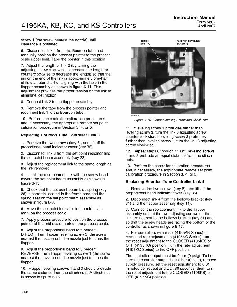
4195KA, KB, KC, and KS ControllersInstruction Manual
Form 5207April 2007
6-22
screw 1 (the screw nearest the nozzle) untilclearance is obtained.
6. Disconnect link 1 from the Bourdon tube andmanually position the process pointer to the processscale upper limit. Tape the pointer in this position.
7. Adjust the length of link 2 (by turning theadjusting screw clockwise to increase the length orcounterclockwise to decrease the length) so that thepin on the end of the link is approximately one-halfof its diameter short of aligning with the hole in theflapper assembly as shown in figure 6-11. Thisadjustment provides the proper tension on the link toeliminate lost motion.
8. Connect link 2 to the flapper assembly.
9. Remove the tape from the process pointer andreconnect link 1 to the Bourdon tube.
10. Perform the controller calibration proceduresand, if necessary, the appropriate remote set pointcalibration procedure in Section 3, 4, or 5.
Replacing Bourdon Tube Controller Link 3
1. Remove the two screws (key 6), and lift off theproportional band indicator cover (key 36).
2. Disconnect link 3 from the set point indicator andthe set point beam assembly (key 23).
3. Adjust the replacement link to the same length asthe link removed.
4. Install the replacement link with the screw headtoward the set point beam assembly as shown infigure 6-13.
5. Check that the set point beam bias spring (key28) is correctly located in the frame bore and thespring seat on the set point beam assembly asshown in figure 6-3.
6. Move the set point indicator to the mid-scalemark on the process scale.
7. Apply process pressure to position the processpointer at the mid-scale mark on the process scale.
8. Adjust the proportional band to 5 percentDIRECT. Turn flapper leveling screw 3 (the screwnearest the nozzle) until the nozzle just touches theflapper.
9. Adjust the proportional band to 5 percentREVERSE. Turn flapper leveling screw 1 (the screwnearest the nozzle) until the nozzle just touches theflapper.
10. Flapper leveling screws 1 and 3 should protrudethe same distance from the clinch nuts. A clinch nutis shown in figure 6-16.
W4191-1 / IL
FLAPPER LEVELINGSCREW
CLINCHNUT
Figure 6-16. Flapper leveling Screw and Clinch Nut
11. If leveling screw 1 protrudes further thanleveling screw 3, turn the link 3 adjusting screwcounterclockwise. If leveling screw 3 protrudesfurther than leveling screw 1, turn the link 3 adjustingscrew clockwise.
12. Repeat steps 8 through 11 until leveling screws1 and 3 protrude an equal distance from the clinchnuts.
13. Perform the controller calibration proceduresand, if necessary, the appropriate remote set pointcalibration procedure in Section 3, 4, or 5.
Replacing Bourdon Tube Controller Link 4
1. Remove the two screws (key 6), and lift off theproportional band indicator cover (key 36).
2. Disconnect link 4 from the bellows bracket (key31) and the flapper assembly (key 11).
3. Connect the replacement link to the flapperassembly so that the two adjusting screws on thelink are nearest to the bellows bracket (key 31) andso that the screw heads are facing the bottom of thecontroller as shown in figure 6-17.
4. For controllers with reset (4195KB Series) orreset and rate adjustments (4195KC Series), turnthe reset adjustment to the CLOSED (4195KB) orOFF (4195KC) position. Turn the rate adjustment(4195KC Series) to the OFF position.
The controller output must be 0 bar (0 psig). To besure the controller output is at 0 bar (0 psig), removesupply pressure, set the reset adjustment to 0.01minutes per repeat and wait 30 seconds; then, turnthe reset adjustment to the CLOSED (4195KB) orOFF (4195KC) position.

4195KA, KB, KC, and KS ControllersInstruction ManualForm 5207April 2007
6-23
W4195 / IL
BELLOWS BRACKET(KEY 31)
LINK 4 ADJUSTMENTSCREW HEADS
Figure 6-17. Position of Link 4 Adjustment Screws
5. Adjust the proportional band to 5 percentREVERSE and move the set point indicator to theprocess scale upper limit.
6. Disconnect link 1 from the Bourdon tube andmove the process pointer to the process scale lowerlimit. Tape the process pointer in this position.
7. Apply the correct supply pressure to thecontroller. The output of the controller should bewithin 0.14 bar (2 psig) of the supply pressure. If not,adjust flapper leveling screw 1 (the screw nearestthe nozzle) until the output is within 0.14 bar (2 psig)of supply pressure.
8. Loosen the two adjusting screws on link 4.Connect the free end of the link to the bellowsbracket and allow the link to find its free length.
9. Tighten the two adjusting screws on the link.
10. Raise link 4 out of the hole in the bellowsbracket (key 31) and ensure that it drops back intothe hole under its own weight. If not, repeat steps 8and 9.
11. For a controller with reset, adjust the resetadjustment to 0.01 minutes per repeat. The rateadjustment (4195KC) should remain in the OFFposition.
12. The controller output should be within 0.14 bar(2 psig) of the supply pressure. If not, adjust flapperleveling screw 1 (the screw nearest the nozzle) untilthe output is within 0.14 bar (2 psig) of supplypressure.
13. Remove the tape from the process pointer andconnect link 1 to the Bourdon tube.
14. Perform the controller calibration proceduresand, if necessary, the appropriate remote set pointcalibration procedure in Section 3, 4, or 5.
Bourdon Tube Travel Stop Installationand Adjustment
WARNING
Refer to the Maintenance WARNINGon page 6-1.
Note
The process indicator should becalibrated before installing oradjusting travel stops. Refer to theappropriate process indicator zeroand span calibration procedure inSection 3, 4, or 5.
Refer to figure 6-18 for adjustment locations andfigure 7-1 for key number locations.
The lower travel stop is necessary only if theoperating range lower limit is greater than 0 bar or 0psig (elevated zero) For example: The process scalelimits may be 0 to 300 psig, but the range ofoperation is 150 to 300 psig. In this example theelevated zero is 150 psig and the lower travel stopwould be adjusted for 5 percent of the process scalespan less than 150 psig(150 − (0.05 X 300) = 135 psig).
1. Remove the two screws (key 6), and lift off theproportional band indicator cover (key 36).
2. Set the proportional band between DIRECT andREVERSE.
3. Install the upper travel stop (key 73) or upper andlower travel stops (keys 73 and 74) with the machinescrews (keys 75 and 76). Do not tighten themachine screws (key 75) that secure the uppertravel stop. If only the upper travel stop is installed,go to step 10. Otherwise proceed with step 4.
4. If the operating range lower limit is 0 bar (0 psig),and a lower travel stop is installed, adjust the lowertravel stop adjustment so it does not interfere withthe Bourdon tube. Tighten the lower travel stopadjustment lock nut and proceed to step 10. If theoperating range lower limit is other than 0 psig(elevated zero), perform steps 5 through 15.
5. If the process scale lower limit is other than 0psig, adjust the process pressure to 5 percent of theprocess scale span less than the operating rangelower limit (see example at the beginning of thisprocedure).
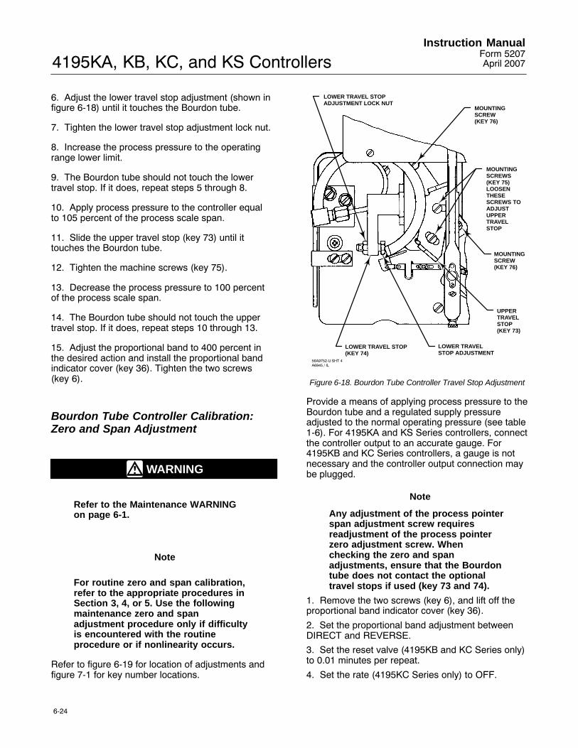
4195KA, KB, KC, and KS ControllersInstruction Manual
Form 5207April 2007
6-24
6. Adjust the lower travel stop adjustment (shown infigure 6-18) until it touches the Bourdon tube.
7. Tighten the lower travel stop adjustment lock nut.
8. Increase the process pressure to the operatingrange lower limit.
9. The Bourdon tube should not touch the lowertravel stop. If it does, repeat steps 5 through 8.
10. Apply process pressure to the controller equalto 105 percent of the process scale span.
11. Slide the upper travel stop (key 73) until ittouches the Bourdon tube.
12. Tighten the machine screws (key 75).
13. Decrease the process pressure to 100 percentof the process scale span.
14. The Bourdon tube should not touch the uppertravel stop. If it does, repeat steps 10 through 13.
15. Adjust the proportional band to 400 percent inthe desired action and install the proportional bandindicator cover (key 36). Tighten the two screws(key 6).
Bourdon Tube Controller Calibration:Zero and Span Adjustment
WARNING
Refer to the Maintenance WARNINGon page 6-1.
Note
For routine zero and span calibration,refer to the appropriate procedures inSection 3, 4, or 5. Use the followingmaintenance zero and spanadjustment procedure only if difficultyis encountered with the routineprocedure or if nonlinearity occurs.
Refer to figure 6-19 for location of adjustments andfigure 7-1 for key number locations.
LOWER TRAVEL STOPADJUSTMENT LOCK NUT
LOWER TRAVEL STOP(KEY 74)
LOWER TRAVEL STOP ADJUSTMENT
UPPER TRAVEL STOP(KEY 73)
MOUNTINGSCREW(KEY 76)
MOUNTINGSCREW(KEY 76)
MOUNTINGSCREWS(KEY 75)LOOSENTHESESCREWS TOADJUSTUPPER TRAVELSTOP
56A9752-U SHT 4A6945 / IL
Figure 6-18. Bourdon Tube Controller Travel Stop Adjustment
Provide a means of applying process pressure to theBourdon tube and a regulated supply pressureadjusted to the normal operating pressure (see table1-6). For 4195KA and KS Series controllers, connectthe controller output to an accurate gauge. For4195KB and KC Series controllers, a gauge is notnecessary and the controller output connection maybe plugged.
Note
Any adjustment of the process pointerspan adjustment screw requiresreadjustment of the process pointerzero adjustment screw. Whenchecking the zero and spanadjustments, ensure that the Bourdontube does not contact the optionaltravel stops if used (key 73 and 74).
1. Remove the two screws (key 6), and lift off theproportional band indicator cover (key 36).
2. Set the proportional band adjustment betweenDIRECT and REVERSE.
3. Set the reset valve (4195KB and KC Series only)to 0.01 minutes per repeat.
4. Set the rate (4195KC Series only) to OFF.

4195KA, KB, KC, and KS ControllersInstruction ManualForm 5207April 2007
6-25
RATEADJUSTMENT RESET
ADJUSTMENTW3599-1 / IL
4195KC SERIES
SCREW 1
SCREW 2
SCREW 3
PROCESSPOINTER SPANADJUSTMENT
REMOTE SET POINTSPAN ADJUSTMENT(SUFFIX LETTER M)
SIDE VIEW OFSET POINT/PROCESS
INDICATOR ASSEMBLY
SIDE VIEW OFCONTROLLER SHOWING
FLAPPER LEVELING SCREWS39A1126-BA6731 / IL
59A9752-S SHT 1NOTES:AVAILABLE ON 4195KB SERIES ONLY.AVAILABLE ON 4195KB AND KC SERIES SUFFIX
LETTER F ONLY.
POINTER ZEROADJUSTMENT
FRONT VIEW, 4195KB SERIESW6833 / IL
POINTER ZEROADJUSTMENTLOCKING SCREW
PROCESS POINTERSPAN ADJUSTMENT
ANTI-RESET WINDUPRELIEF VALVE
REMOTE SET POINTZERO ADJUSTMENT
REMOTE SET POINTZERO ADJUSTMENTLOCKING SCREW
RESETADJUSTMENT
ANTI-RESET WINDUPVALVE ADJUSTING SCREW
1
1
2
2
2
Figure 6-19. 4195K Controller Calibration Adjustment Locations
4195KA, KB, KC, and KS ControllersInstruction Manual
Form 5207April 2007
6-26
5. For a controller with manual set point, move theset point indicator to the mid-scale mark on theprocess scale. For a controller with remote set point,adjust the remote set point pressure until the setpoint indicator is at the mid-scale mark on theprocess scale.
6. Apply process pressure equal to the mid-scalevalue of the process scale span.
7. The process pointer should be aligned with thepointer subassembly as shown in figure 6-15. If not,loosen the zero adjustment locking screw and adjustthe zero adjustment screw to align the processpointer with the pointer subassembly. Tighten thezero adjustment locking screw.
8. The process pointer should indicate mid-scale ±3percent of the process scale span. If not, loosen thescrews in link 1 and adjust the length so that theprocess pointer points to the mid-scale mark on theprocess scale. Tighten the screws.
9. Apply process pressure equal to the processscale lower limit.
10. The process pointer should indicate the processscale lower limit. If not, loosen the zero adjustmentlocking screw and adjust the zero adjustment screwuntil the process pointer indicates the lower limit.Tighten the zero adjustment locking screw.
11. Apply process pressure equal to the processscale upper limit.
12. The pointer should indicate the process scaleupper limit. If not, proceed as follows:
a. If the pointer indicates less than the processscale upper limit, rotate the pointer spanadjustment clockwise to increase the span.Adjust the span adjustment screw to correct forhalf of the error.
b. If the pointer indicates greater than theprocess scale upper limit, rotate the pointer spanadjustment counterclockwise to decrease thespan. Adjust the span adjustment screw tocorrect for half of the error.
13. Repeat steps 9 through 12 until the zero andspan indications are within ±1 percent of the scalelimits with no further adjustment. If proper span isachieved, proceed to step 15. If the span adjustment
screw is adjusted to its limit and the span is still tooshort or too long, proceed with step 14.
14. Within the process pointer subassembly, thereare three holes for the connection of link 1. Useprocedure (a.) or (b.) below to make the coarsespan adjustment with link 1.
a. If the span is short (process pointer indicationis less than the process scale upper limit),disconnect link 1 from the process pointersubassembly and move the link to the lowesthole (the hole nearest the pointer pivot). Returnto step 9.
b. If the span is long, (process pointer indicationis greater than the process scale upper limit),disconnect link 1 from the process pointersubassembly and move the link to the highesthole (hole furthermost from the pointer pivot),and return to step 9.
15. Apply process pressure equal to the mid-scalevalue of the process scale span. The processpointer should indicate mid-scale ±2 percent of theprocess scale span. If the process pointer error is ±2percent or less, proceed to step 17. If the processpointer error is greater than ±2 percent, loosen thetwo Bourdon tube mounting screws (key 384, figure7-2). Also, loosen the two screws (keys 379 and380, figure 7-2) holding the process tubing retainer.
16. Slide the Bourdon tube up or down and tightenthe four screws loosened in step 15. Several triesmay be required to determine the direction in whichto move the Bourdon tube to obtain the requiredaccuracy. Return to step 5.
17. Adjust the process pointer to within ±1 percentof the mid-scale mark by loosening the zeroadjustment locking screw and adjusting the zeroadjustment screw. Tighten the zero adjustmentlocking screw. This distributes the error over theentire process scale and keeps all points within ±1percent of the process scale span.
18. Adjust the process pressure to the lower andupper limits of the process scale span to make surethe process pointer is still within ±1 percent of thelower and upper scale limits.
19. Perform the flapper alignment procedure and, ifnecessary, the appropriate remote set pointcalibration procedure in Section 3, 4, or 5.

4195KA, KB, KC, and KS ControllersInstruction ManualForm 5207April 2007
6-27
Capsular Element ControllerMaintenance and Calibration
Replacing the Capsular ElementAssembly
WARNING
Refer to the Maintenance WARNINGon page 6-1.
Refer to figure 7-5 for key number locations, unlessnoted otherwise.
1. Remove process pressure from the controller.
2. Note the hole location and disconnect link 1 (key90) from the process pointer.
3. Disconnect the process pressure connectionunion (key 93) from the pedestal assembly (key 81).Use two 5/16-inch hex wrenches.
4. Remove the four machine screws (key 127 infigure 7-3) that attach the capsular elementassembly to the indicator assembly (key 101 infigure 7-3).
CAUTION
In the following step, do not lift outthe capsular element assembly byholding the capsular element orlinkages. These parts may bedamaged.
5. Lift out the capsular element assembly by holdingthe tie bar (key 97), mounting plate (key 77), travelstop (key 83), or pedestal assembly (key 81).
6. Position the replacement capsular elementassembly over the mounting screw holes. Install andtighten the mounting screws (key 127 in figure 7-3).
7. Reconnect link 1 (key 90) to the process pointerin the same hole noted in step 2.
8. Reconnect the process pressure connectionunion (key 93).
9. Apply process pressure to the controller andcheck for leaks.
10. Perform the capsular element maintenancecalibration procedure in this section. Perform thecontroller calibration procedures and, if necessary,the appropriate remote set point calibrationprocedure in Section 3, 4, or 5.
Replacing Capsular Element Parts
WARNING
Refer to the Maintenance WARNINGon page 6-1.
CAUTION
Avoid bending or kinking the driveflexure during the followingprocedures. Bending or kinking thedrive flexure can result in productdamage, as well as impairedperformance.
Refer to figure 7-5 for capsular element key numberlocations. Refer to figure 6-19 for adjustmentlocations and refer to figure 7-4 for indicatorassembly (without process sensing element) partlocations.
Replacing the Long Pivot Assembly
1. Remove process pressure from the controller.
2. Remove the tie bar (key 97) from the capsularelement assembly by removing the mounting screws(key 103).
3. Note the hole position of link 5 (key 88) anddisconnect the link from the pivot adjustment arm onthe long pivot clevis assembly (key 78).
4. Using an Allen wrench, remove the cap screwand washer (keys 12 and 13) that attach the driveflexure (key 79) to the pivot adjustment arm of thelong pivot clevis assembly. Take care not to bend orkink the drive flexure.
5. Remove the two screws (key 102) attaching thelong pivot clevis assembly to the mounting plate (key 77).

4195KA, KB, KC, and KS ControllersInstruction Manual
Form 5207April 2007
6-28
END BUSHINGBEARING
SHAFT
BEARING
END BUSHING
ADJUSTMENT ARM
NOTE:BEFORE TIGHTENING THE DRIVE FLEXURE MOUNTING SCREWS,
POSITION THE SHAFT SO THE END BUSHINGS “FLOAT” IN THE BEARINGS.
26A9784-EA5682 / IL
1
1
1
Figure 6-20. Cutaway of Long Pivot Clevis Assembly
6. Loosen the screw on the pivot adjustment arm ofthe replacement pivot clevis assembly, and adjustthe arm to the same length as the arm on the pivotassembly being replaced.
7. Attach the replacement pivot clevis assembly tothe mounting plate with the two mounting screws(key 102).
8. Loosely connect the drive flexure to the pivotadjustment arm on the new pivot clevis assembly.
See figure 6-20. The adjustment arm of the longpivot clevis assembly is connected to a shaft thatturns on bushings at each end of the shaft. In thenext step, position the shaft so that both bushings��float�� inside the bearings and do not rest againstthe end of either bearing.
9. Apply 75 percent of the capsular element rangeto the capsule. The drive flexure should be straightand horizontal. Before tightening the drive flexurecap screws (key 12), hold the pivot shaft in themiddle of the bushing end play. Be sure neitherbushing is resting against the inside end of eitherbearing. Tighten the drive flexure cap screws to holdthe pivot shaft in position. Adjust the length of thepivot adjustment arm as needed until the driveflexure is horizontal. Take care not to kink or twistthe flexure when tightening the screws.
10. Connect the left-hand end of link 5 (key 88) tothe pivot adjustment arm in the hole position notedin step 3.
11. Replace the tie bar (key 97).
12. Perform the capsular element maintenancecalibration procedure in this section. Perform thecontroller calibration procedures and, if necessary,perform the appropriate remote set point calibrationprocedure in Section 3, 4, or 5.
Replacing the Short Pivot Assembly
1. Remove process pressure from the controller.
2. Note the hole positions of links 1 and 5 (keys 88and 90) and disconnect the links from the short pivotclevis assembly (key 89). Also, note the screwposition of the linearity adjustment for laterreference.
3. Remove the two machine screws (key 102)attaching the short pivot clevis assembly (key 89) tothe mounting plate (key 77) and remove the pivotclevis assembly.
4. Set the linearity adjustment screw in thereplacement pivot assembly to approximately thesame location as noted in step 2.
5. Position the replacement short pivot clevisassembly on the mounting plate, and attach it withthe two machine screws.
6. Attach links 1 and 5 (keys 88 and 90) in the samehole position as noted in step 2.
7. Perform the capsular element maintenancecalibration procedures in this section. Perform thecontroller calibration procedures and, if necessary,the appropriate remote set point calibrationprocedure in Section 3, 4, or 5.
Replacing the Process Drive Flexure
1. Set the process pressure to 75 percent of thecapsular element range.
2. Remove the tie bar (key 97) from the capsularelement assembly by removing the mounting screws(key 103).
3. Using an Allen wrench, remove the cap screwsand washers (keys 12 and 13) to disconnect thedrive flexure (key 79) from the drive bracketassembly (key 84) and from the pivot adjustmentarm of the long pivot clevis assembly (key 78).Remove the drive flexure.
4. Loosely connect the replacement drive flexure,making sure it is straight and horizontal.

4195KA, KB, KC, and KS ControllersInstruction ManualForm 5207April 2007
6-29
LINK 5 LINK 1 LINK 4 LINK 4 ADJUSTMENT
LINK 3 ADJUSTMENTLINK 2 ADJUSTMENT
LINEARITYADJUSTMENTSCREW
LINK 2 LINK 3W4769 / IL
Figure 6-21. Capsular Element Controller Link Locations and Adjustments
Note
See figure 6-20. The adjustment arm ofthe long pivot clevis assembly isconnected to a shaft that turns onbushings at each end of the shaft. Inthe next step, position the shaft sothat both bushings ‘‘float’’ inside thebearings and do not rest against theend of either bearing.
5. Before tightening the drive flexure cap screws(key 12), hold the pivot shaft in the middle of thebushing end play. Be sure neither bushing is restingagainst the inside end of either bearing. Tighten thedrive flexure cap screws to hold the pivot shaft inposition. Take care not to kink or twist the flexurewhen tightening the screws.
6. Perform the capsular element maintenancecalibration procedure in this section. Perform thecontroller calibration procedures and, if necessary,the appropriate remote set point calibrationprocedure in Section 3, 4, or 5.
Replacing the Process Tubing
1. Remove process pressure from the controller.
2. Using two open-end 5/16-inch wrenches,disconnect the process tubing (keys 91 or 92) at thepedestal assembly (key 81) and at the bottom of thecontroller case. Remove the tubing.
3. Install the replacement tubing, and tighten allconnections. Check for leaks.
4. Perform the controller calibration procedures and,if necessary, the appropriate remote set pointcalibration procedure in Section 3, 4, or 5.
Replacing Capsular Element ControllerLinks
WARNING
Refer to the Maintenance WARNINGon page 6-1.
This section describes the separate replacement offive links in the controller. Figure 6-21 shows thelocation of each link. To clarify the location of eachlink, the links are numbered as follows:
� Link 1 connects the short pivot clevis assemblyand the process pointer
� Link 2 connects the process pointer and theflapper assembly (key 11)
� Link 3 connects the set point indicator and theset point beam assembly (key 23)
� Link 4 (key 65) connects the flapper assemblyand the bellows bracket (key 31)
� Link 5 (key 88 in figure 7-5) connects the shortpivot clevis assembly (key 89) and the long pivotclevis assembly (key 78).

4195KA, KB, KC, and KS ControllersInstruction Manual
Form 5207April 2007
6-30
Replacing Capsular Element Controller Link 1
1. Remove the two screws (key 6), and lift off theproportional band indicator cover (key 36).
2. Note the hole position of link 1 and disconnectthe link from the short pivot clevis assembly andfrom the process pointer. Remove the link.
3. Attach the replacement link in the same holesnoted in step 2 to the process pointer and the shortpivot clevis assembly. If you do not know in whichhole in the process pointer the link was connected,place it in the middle hole. If during the processindicator zero and span calibration, the pointer willnot travel the full scale, even after full spanadjustment, move the link to the bottom hole (thehole nearest the pointer pivot). If the process pointerhas too much travel, move the link to the top hole(the hole furthermost from the pointer pivot).
4. Move the set point indicator, either manually orwith remote set point pressure, to the mid-scalemark on the process scale and set the proportionalband between DIRECT and REVERSE.
5. The process pointer should be aligned with thepointer subassembly as shown in figure 6-15. If not,loosen the zero adjustment locking screw and adjustthe process pointer zero adjustment to align theprocess pointer and pointer subassembly. Tightenthe zero adjustment locking screw.
6. Apply process pressure equal to the mid-scalevalue of the process scale span. The processpointer should indicate mid-scale ±3 percent of theprocess scale span. If not, loosen the screw in link 1or link 5, and move the pointer to the mid-scale markon the process scale. Tighten the screw.
7. Perform the controller calibration procedures and,if necessary, the appropriate remote set pointcalibration procedure in Section 3, 4, or 5.
Replacing Capsular Element Controller Link 2
1. Remove the two screws (key 6), and lift off theproportional band indicator cover (key 36).
2. Disconnect link 2 from the process pointer andfrom the flapper assembly (key 11). Remove thelink.
3. Install the replacement link with the screw headnearest the process pointer as shown in figure 6-21.Connect the link to the process pointer only.
4. The process pointer should be lined up with thepointer subassembly as shown in figure 6-15. If not,loosen the zero adjustment locking screw and adjustthe process pointer zero adjustment to align the
pointer with the process pointer subassembly.Tighten the zero adjustment locking screw.
5. Move the set point indicator, manually or withremote set point pressure, to the process scalelower limit and set the proportional band at 5 percentREVERSE. The nozzle should not be touching theflapper. If it is, adjust flapper leveling screw 1 (thescrew nearest the nozzle) until clearance isobtained.
6. Note the hole position and disconnect link 1 fromthe short pivot clevis assembly. Manually positionthe process pointer to the process scale upper limitand tape the process pointer in this position.
7. Adjust the length of link 2 (by turning theadjusting screw clockwise to increase the length orcounterclockwise to decrease the length) so that thepin on the end of the link is approximately one-halfof its diameter short of aligning with the hole in theflapper assembly as shown in figure 6-11. Thisadjustment provides the proper tension on the link toeliminate lost motion.
8. Connect link 2 to the flapper assembly.
9. Remove the tape from the process pointer andreconnect link 1 to the hole in the short pivot clevisassembly noted in step 6.
10. Perform the controller calibration proceduresand, if necessary, the appropriate remote set pointcalibration procedure in Section 3, 4, or 5.
Replacing Capsular Element Controller Link 3
1. Remove the two screws (key 6), and lift off theproportional band indicator cover (key 36).
2. Disconnect link 3 from the set point indicator andthe set point beam assembly (key 23).
3. Adjust the replacement link to the same length asthe link removed.
4. Install the replacement link with the screw headtoward the set point beam assembly as shown infigure 6-21.
5. Check that the set point beam bias spring (key28) is correctly located in the frame bore and thespring seat on the set point beam assembly asshown in figure 6-3.
6. Move the set point indicator to the mid-scalemark on the process scale.
7. Apply process pressure to position the processpointer at the mid-scale mark on the process scale.
8. Adjust the proportional band to 5 percentDIRECT. Turn flapper leveling screw 3 (the screwnearest the nozzle) until the nozzle just touches theflapper.

4195KA, KB, KC, and KS ControllersInstruction ManualForm 5207April 2007
6-31
9. Adjust the proportional band to 5 percentREVERSE. Turn flapper leveling screw 1 (the screwnearest the nozzle) until the nozzle just touches theflapper.
10. Flapper leveling screws 1 and 3 should protrudethe same distance from the clinch nuts. A clinch nutis shown in figure 6-16.
11. If leveling screw 1 protrudes further thanleveling screw 3, turn the link 3 adjusting screwcounterclockwise. If leveling screw 3 protrudesfurther than leveling screw 1, turn the link 3 adjustingscrew clockwise.
12. Repeat steps 8 through 11 until leveling screws1 and 3 protrude an equal distance from the clinchnuts.
13. Perform the controller calibration proceduresand, if necessary, the appropriate remote set pointcalibration procedure in Section 3, 4, or 5.
Replacing Capsular Element Controller Link 4
1. Remove the two screws (key 6), and lift off theproportional band indicator cover (key 36).
2. Disconnect link 4 from the bellows bracket (key31) and the flapper assembly (key 11).
3. Connect the replacement link to the flapperassembly so that the two adjusting screws on thelink are nearest to the bellows bracket (key 31) andso that the screw heads are facing the bottom of thecontroller as shown in figure 6-21.
4. For controllers with reset (4195KB Series) orreset and rate adjustments (4195KC Series), turnthe reset adjustment to the CLOSED (4195KB) orOFF (4195KC) position. Turn the rate adjustment(4195KC Series) to the OFF position.
The controller output must be 0 bar (0 psig). To besure the controller output is at 0 bar (0 psig), removesupply pressure, set the reset adjustment to 0.01minutes per repeat and wait 30 seconds; then, turnthe reset adjustment to the CLOSED (4195KB) orOFF (4195KC) position.
5. Adjust the proportional band to 5 percentREVERSE and move the set point indicator to theprocess scale upper limit.
6. Disconnect link 1 from the pivot arm. Tape theprocess pointer to the process scale lower limit (thelast mark on the left side of the scale).
7. Apply the correct supply pressure to thecontroller. The output of the controller should bewithin 0.14 bar (2 psig) of supply pressure. If not,adjust flapper leveling screw 1 (the screw nearest
the nozzle) until the output is within 0.14 bar (2 psig)of supply pressure.
8. Loosen the two adjusting screws on link 4.Connect the free end of the link to the bellowsbracket and allow the link to find its free length.
9. Tighten the two adjusting screws on the link.
10. Raise link 4 out of the hole in the bellowsbracket (key 31) and ensure that it drops back intothe hole under its own weight. If not, repeat steps 8and 9.
11. For a controller with reset, adjust the resetadjustment to 0.01 minutes per repeat. The rateadjustment (4195KC) should remain in the OFFposition.
12. The controller output should be within 0.14 bar(2 psig) of the supply pressure. If not, adjust flapperleveling screw 1 (the screw nearest the nozzle) untilthe output is within 0.14 bar (2 psig) of supplypressure.
13. Remove the tape from the process pointer andconnect link 1 to the pivot arm.
14. Perform the controller calibration proceduresand, if necessary, the appropriate remote set pointcalibration procedure in Section 3, 4, or 5.
Replacing Capsular Element Controller Link 5
1. Remove the two screws (key 6), and lift off theproportional band indicator cover (key 36).
2. Note the location of the connection holes anddisconnect both ends of link 5 (key 88) from thelever arms of the two pivot assemblies. Refer tofigure 6-22 for parts locations.
3. Loosen the adjustment screw on the replacementlink and adjust the length to match the original link.Tighten the adjustment screw.
4. Attach the replacement link to the two lever armsin the same holes noted in step 2.
5. Move the set point indicator, either manually orwith remote set point pressure, to the mid-scalemark on the process scale and set the proportionalband between DIRECT and REVERSE.
6. The process pointer should be aligned with thepointer subassembly as shown in figure 6-15. If not,loosen the zero adjustment locking screw and adjustthe process pointer zero adjustment to align theprocess pointer and pointer subassembly. Tightenthe zero adjustment locking screw.
7. Apply process pressure equal to the mid-scalevalue of the process scale span. The processpointer should indicate the mid-scale ±3 percent ofthe scale span. If not, loosen the screw in link 1 or
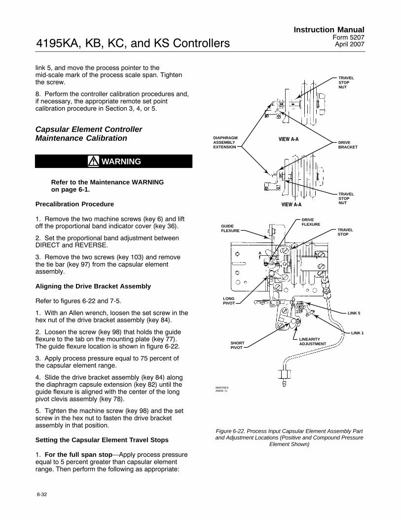
4195KA, KB, KC, and KS ControllersInstruction Manual
Form 5207April 2007
6-32
link 5, and move the process pointer to themid-scale mark of the process scale span. Tightenthe screw.
8. Perform the controller calibration procedures and,if necessary, the appropriate remote set pointcalibration procedure in Section 3, 4, or 5.
Capsular Element ControllerMaintenance Calibration
WARNING
Refer to the Maintenance WARNINGon page 6-1.
Precalibration Procedure
1. Remove the two machine screws (key 6) and liftoff the proportional band indicator cover (key 36).
2. Set the proportional band adjustment betweenDIRECT and REVERSE.
3. Remove the two screws (key 103) and removethe tie bar (key 97) from the capsular elementassembly.
Aligning the Drive Bracket Assembly
Refer to figures 6-22 and 7-5.
1. With an Allen wrench, loosen the set screw in thehex nut of the drive bracket assembly (key 84).
2. Loosen the screw (key 98) that holds the guideflexure to the tab on the mounting plate (key 77).The guide flexure location is shown in figure 6-22.
3. Apply process pressure equal to 75 percent ofthe capsular element range.
4. Slide the drive bracket assembly (key 84) alongthe diaphragm capsule extension (key 82) until theguide flexure is aligned with the center of the longpivot clevis assembly (key 78).
5. Tighten the machine screw (key 98) and the setscrew in the hex nut to fasten the drive bracketassembly in that position.
Setting the Capsular Element Travel Stops
1. For the full span stop�Apply process pressureequal to 5 percent greater than capsular elementrange. Then perform the following as appropriate:
DIAPHRAGMASSEMBLYEXTENSION
TRAVELSTOPNUT
TRAVELSTOPNUT
DRIVEBRACKET
GUIDEFLEXURE
LONGPIVOT
SHORTPIVOT
LINEARITYADJUSTMENT
LINK 1
LINK 5
TRAVELSTOP
DRIVEFLEXURE
AA
VIEW A-A
VIEW A-A
58A0708-EA6946 / IL
Figure 6-22. Process Input Capsular Element Assembly Partand Adjustment Locations (Positive and Compound Pressure
Element Shown)

4195KA, KB, KC, and KS ControllersInstruction ManualForm 5207April 2007
6-33
� For positive or compound pressure with athree-capsule stack, loosen the machine screws(key 139) that secure the travel stop (key 83) to themounting plate (key 77). Slide the travel stop until itis just touching the end of the capsule stack. Tightenthe travel stop mounting screws to lock it intoposition. Decrease the input pressure to 100 percentof the capsular element range and make sure thecapsule stack is not contacting the travel stop (key83).
� For positive or compound pressure with atwo-capsule stack, loosen the set screw (key 87) inthe travel stop nut (key 86) between the travel stop(key 83) and the capsule stack. Slide the nut alongthe diaphragm capsule extension (key 130) until itjust touches the travel stop (key 83). Tighten the setscrew to lock the travel stop nut in position.Decrease the input pressure to 100 percent of thecapsular element range and make sure the travelstop nut is not contacting the travel stop (key 83).
� For vacuum pressure, loosen the set screw(key 87) in the travel stop nut (key 86) on the end ofthe diaphragm capsule extension (key 132 or 133).The nut is located on the opposite side of the travelstop (key 83) from the capsule. Slide the nut alongthe diaphragm capsule extension until it just touchesthe travel stop (key 83). Tighten the set screw tolock the travel stop nut in position. Decrease thevacuum to 100 percent of the capsular elementrange and make sure the travel stop nut is notcontacting the travel stop (key 83).
2. For the zero stop�perform the following asappropriate:
� If the lower limit of the capsular element rangeis 0 bar (0 psig), adjust the process pressure to 0bar (0 psig). Slide the zero travel stop nut (key 86)along the diaphragm assembly extension until it isapproximately 0.4 mm (1/64-inch) away from thetravel stop. Tighten the set screw to lock the travelstop nut in position.
� If the lower limit of the capsular element rangeis other than 0 bar (0 psig), adjust the processpressure to 5 percent below the capsular elementrange lower limit and slide the travel stop nut (key86) along the diaphragm extension until it justtouches the travel stop (key 83). Tighten the setscrew. Increase the input pressure to the capsularelement range lower limit and make sure the travelstop nut is not contacting the travel stop (key 83).
Aligning the Capsular Element Linkage
1. Adjust the process pressure to 75 percent of thecapsular element range. The drive flexure (key 79)should be straight and horizontal. If it is not, proceedas follows:
a. Loosen the screw on the pivot adjustment armon the long pivot clevis assembly (key 78) andthe two screws mounting the drive flexure.
b. Adjust the length of the pivot adjustment armso that the drive flexure is parallel to thecenterline of the capsules. Tighten the screw toset the length of the pivot adjustment arm in thatposition.
Note
See figure 6-20. The adjustment arm ofthe long pivot clevis assembly isconnected to a shaft that turns onbushings at each end of the shaft. Inthe next step, position the shaft sothat both bushings ‘‘float’’ inside thebearings and do not rest against theend of either bearing.
c. Before retightening the drive flexure screws,hold the long pivot clevis assembly shaft in themiddle of the bushing end play. Be sure neitherbushing is resting against the inside end of eitherbearing.
d. Tighten the drive flexure screws to hold thepivot clevis assembly shaft in position.
2. Set the linearity adjustment screw on the shortpivot clevis assembly so the two arms of the shortpivot clevis assembly are parallel. The linearityadjustment screw should be near the center of itsslot.3. Make certain that the process pointer and pointersubassembly are aligned as shown in figure 6-15. Ifnot, loosen the zero adjustment locking screw andadjust the process pointer zero adjustment screw toalign the process pointer and pointer subassembly.Tighten the zero adjustment locking screw.4. Adjust the process pressure to 50 percent of thecapsular element range.
5. Loosen the screw on link 5 (key 88) and adjustthe link length so that the pivot arms of the shortpivot clevis assembly (key 89) and the long pivotclevis assembly (key 78) are parallel. Tighten thescrew.6. Complete the maintenance calibration byperforming the zero and span adjustments in thefollowing procedure.
4195KA, KB, KC, and KS ControllersInstruction Manual
Form 5207April 2007
6-34
Capsular Element Controller Zero and SpanAdjustment
Note
For routine zero and span calibration,refer to the appropriate procedures inSection 3, 4, or 5. Use the followingmaintenance zero and spanadjustment procedure only if difficultyis encountered with the routineprocedure or if nonlinearity occurs.
Provide a means of applying process pressure to thesensing element and a regulated supply pressureadjusted to the normal operating pressure (see table1-6). Plug the controller output or connect it to agauge. Monitoring the controller output is notnecessary. However, the flapper should not contactthe nozzle at any time while performing thisprocedure. If it does, adjust flapper screw 2 (the onenearest the nozzle) to provide clearance. Refer tofigure 6-19 for the adjustment locations. Refer tofigure 7-1 for the key number locations.
Note
Any adjustment of the process pointerspan adjustment screw requiresreadjustment of the process pointerzero adjustment screw.
1. Remove the two machine screws (key 6) and liftoff the proportional band indicator cover (key 36).
2. Set the proportional band between DIRECT andREVERSE.
3. Adjust the reset (4195KB and KC Series only) to0.01 minutes per repeat.
4. Adjust the rate (4195KC Series only) to OFF.
5. For a controller with manual set point, move theset point indicator to the mid-scale mark on theprocess scale. For a controller with remote set point,adjust the remote set point pressure until the setpoint indicator is at the mid-scale mark on theprocess scale.
6. Apply process pressure equal to the mid-scalevalue of the process scale span.
7. The process pointer should be aligned with thepointer subassembly as shown in figure 6-15. If not,loosen the zero adjustment locking screw and adjustthe zero adjustment screw to align the processpointer with the pointer subassembly. Tighten thezero adjustment locking screw.
8. The process pointer should indicate mid-scale ±3percent of the process scale span. If not, loosen thescrew on either link 1 or link 5 and adjust the lengthso that the process pointer points to the mid-scalemark on the process scale. Tighten the screw.
9. Apply process pressure equal to the processscale lower limit.
10. The process pointer should indicate the processscale lower limit. If not, loosen the zero adjustmentlocking screw and adjust the zero adjustment screwuntil the process pointer indicates the lower limit.Tighten the zero adjustment locking screw.
11. Apply process pressure equal to the processscale upper limit.
12. The process pointer should indicate the processscale upper limit. If not, proceed as follows:
a. If the pointer indicates less than the processscale upper limit, rotate the pointer spanadjustment clockwise to increase the span.Adjust the span adjustment screw to correct forone-half of the error.
b. If the pointer indicates greater than theprocess scale upper limit, rotate the pointer spanadjustment counterclockwise to decrease thespan. Adjust the span adjustment screw tocorrect for one-half of the error.
13. Repeat steps 9 through 12 until the zero andspan indications are within ±1 percent of the scalelimits with no further adjustment. If proper span isachieved, proceed to step 16. If the span adjustmentscrew is adjusted to its limit and the span is still tooshort or too long, proceed with step 14.
14. Within the process pointer subassembly, thereare three holes for the connection of link 1. Useprocedure (a.) or (b.) below to make the coarsespan adjustment with link 1.
a. If the span is short (process pointer indicationis less than the process scale upper limit),disconnect link 1 from the process pointersubassembly, move the link to the lowest hole(the hole nearest the pointer pivot), and return tostep 9. If the link is already in the lowest hole,proceed to step 15.
b. If the span is long, (process pointer indicationis greater than the process scale upper limit),disconnect link 1 from the process pointersubassembly, move the link to the highest hole(the hole furthermost from the pointer pivot), andreturn to step 9. If the link is already in thehighest hole, proceed to step 15.

4195KA, KB, KC, and KS ControllersInstruction ManualForm 5207April 2007
6-35
PIVOTASSEMBLY A
GUIDEFLEXURE MOUNTING
SCREW
LINK A ADJUSTMENTSCREW
LINK B
LINEARITYADJUSTMENT
PIVOTASSEMBLY B
MOUNTINGSCREWTIE BAR
REMOTE SET POINT ZERO ADJUSTMENT SCREWZERO ADJUSTMENT LOCKING SCREW
CAPSULES
UPPER TRAVELSTOP
LOWER TRAVELSTOP
DRIVE FLEXURE
SIDE VIEWFRONT VIEW36A9751-CB1668-4 / IL
Figure 6-23. Remote Set Point (suffix letter M) Parts and Adjustment Locations
15. At either end of link 5, there are four holes inwhich the link may be connected. A coarse spanadjustment can be made by moving both ends of link5 up or down.
a. If the span is short (process pointer indicationis less than the process scale upper limit),disconnect both ends of link 5, move the linkdown one set of holes, and return to step 6.
b. If the span is long (process pointer indicationis greater than the process scale upper limit),disconnect both ends of link 5, move the link upone set of holes, and return to step 6.
16. Apply process pressure equal to the mid-scalevalue of the process scale span. The processpointer should indicate mid-scale ±2 percent of thescale span. If the process pointer error is ±2 percentor less, proceed to step 17. If the process pointererror exceeds ±2 percent, the linearity can be
improved with the linearity adjustment. See figure6-22 for the linearity adjustment screw location.
a. If the error at mid-scale is high (processpointer is to the right side of the mid-scale mark),loosen the linearity adjustment screw and slide itupward in the curved slot. Tighten the screw andreturn to step 6.
b. If the error at mid-scale is low (processpointer is to the left side of the mid-scale mark),loosen the linearity adjustment screw and slide itdownward in the curved slot. Tighten the screwand return to step 6.
17. Adjust the process pointer to within ±1 percentof the mid-scale mark by loosening the zeroadjustment locking screw and adjusting the zeroadjustment screw. Tighten the zero adjustmentlocking screw. This distributes the error over theentire process scale and keeps all points within ±1percent of the process scale span.

4195KA, KB, KC, and KS ControllersInstruction Manual
Form 5207April 2007
6-36
18. Adjust the process pressure to the lower andupper limits of the scale span to make sure theprocess pointer is still within ±1 percent of the lowerand upper scale limits.
19. Perform the flapper alignment procedure and, ifnecessary, the appropriate remote set pointcalibration procedure in Section 3, 4, or 5.
Remote Set Point (suffix letter M)Maintenance
Replacing the Remote Set PointAssembly
WARNING
Refer to the Maintenance WARNINGon page 6-1.
Use the following procedures to replace the remoteset point assembly. Figure 6-23 shows the partlocations. Refer to figure 7-6 for key numberlocations.
Note
Remove the supply pressure gaugebefore attempting to remove thecapsular element assembly.
1. Decrease the remote set point pressure to 0 bar(0 psig).
2. Remove the supply pressure gauge.
3. Remove the pressure connection (key 93) at thepedestal assembly (key 105). Use two 5/16 inchwrenches.
4. Disconnect link B (key 126) from the connectionhole on the set point indicator.
5. Remove the three mounting screws (keys 120and 140) that attach the remote set point assemblyto the process/set point indicator assembly. Figure6-23 shows the mounting screw locations.
CAUTION
In the following step, do not lift outthe remote set point assembly byholding the capsular element orlinkages. These parts may bedamaged.
6. Lift out the remote set point assembly by holdingthe tie bar (key 106), mounting plate (key 111),travel stop (key 83), or pedestal assembly (key 105).
7. Align the replacement assembly with themounting screw holes. Replace the mountingscrews.
8. Reconnect the remote set point pressureconnection union (key 93). Apply full remote setpoint pressure and check for leaks.
9. Connect link B (key 126) to the connecting holeon the set point indicator.
10. Replace the supply pressure gauge.
11. Perform the remote set point maintenancecalibration procedure. Perform the appropriateprocess indicator zero and span calibration andflapper alignment procedure in Section 3, 4, or 5.
Replacing Remote Set Point AssemblyParts
WARNING
Refer to the Maintenance WARNINGon page 6-1.
CAUTION
Avoid bending or kinking the driveflexure during the followingprocedures. Bending or kinking thedrive flexure can result in productdamage, as well as impairedperformance.
Figure 6-23 shows the parts and adjustmentlocations. Refer to figure 7-6 for key numberlocations.
Replacing Pivot Assembly A (Key 114)
1. Decrease the remote set point pressure to 0 bar(0 psig).
2. Remove the two screws (key 103) and removethe tie bar (key 106).

4195KA, KB, KC, and KS ControllersInstruction ManualForm 5207April 2007
6-37
3. Note where link A is connected. Disconnect linkA (key 116) from the lever arm on pivot assembly A(key 114).
4. Disconnect the drive flexure (key 79) from theadjustment arm of pivot assembly A. Be careful notto bend or kink the drive flexure.
5. Remove the screw (key 122), washer (key 123),and nut (key 124) that attach the guide flexure (key119) to the top of the pivot assembly.
6. Remove the pivot screw and spring washer (keys109 and 112) and the mounting screw (key 102)attaching the pivot assembly to the mounting plate(key 111). Lift out pivot assembly A.
7. Loosen the adjustment screw (key 118) on theadjustment arm of the replacement pivot assembly,and set the arm to the same length as the arm onthe pivot assembly being replaced. Tighten thescrew.
8. To replace the pivot assembly, first put the springwasher (key 112) on the screw (key 109). Then,insert the screw through the replacement pivotassembly and into the mounting plate and tighten.Install the mounting screw (key 102) and tighten.
9. Connect the guide flexure (key 119) to the top ofthe replacement pivot assembly with the screw (key122), washer (key 123), and nut (key 124) as it wasbefore. The guide flexure should be straight andhorizontal as shown in figure 6-23. If not, loosen thescrews (key 122) and retighten to eliminate anybowing. Loosen the screws (key 139) and raise orlower the pedestal assembly (key 105) to get the linkhorizontal. Retighten the screws (key 139) andensure the diaphragm assembly extension (key 134)is centered in the upper travel stop (key 83) hole.
10. Apply remote set point pressure equal to 50percent of the remote set point input range.
Note
See figure 6-20. The adjustment arm ofthe remote set point pivot assembly Aturns on a bushing at each end of theshaft supporting the adjustment arm.In the next step, position the shaft soboth bushings ‘‘float’’ inside thebearings and do not rest against theend of either bearing.
11. Connect the drive flexure (key 79) to the arm onthe replacement pivot assembly, making sure itstays straight and vertical. Adjust the length of thepivot arm, if necessary, until the flexure is vertical.
Before tightening the drive flexure screws, hold thepivot assembly shaft in the middle of the bushingend play. Be sure neither bushing is resting againstthe inside end of either bearing. Tighten the driveflexure screws to hold pivot assembly A in thisposition. Do not bend or twist the flexure whentightening the screws.
12. Decrease the remote set point pressure to 0 bar(0 psig).
13. Connect the end of link A (key 116) to the pivotlever arm in the same holes noted in step 3.
14. Replace the tie bar (key 106).
15. Perform the remote set point maintenancecalibration procedure. Perform the appropriateprocess indicator zero and span calibration andflapper alignment procedures in Section 3, 4, or 5.
Replacing Pivot Assembly B (Key 115)
1. Decrease the remote set point pressure to 0 bar(0 psig).
2. Note the holes where links A and B areconnected. Disconnect links A and B (keys 116 and126) from the arms of pivot assembly B (key 115).
3. Remove the two screws (key 102) that attachpivot assembly B to the mounting plate (key 111).Remove the pivot assembly.
4. Loosen the linearity adjustment screw on thereplacement pivot assembly and set it in the sameposition as the adjustment on the original pivotassembly. Tighten the screw.
5. Set the replacement pivot assembly on themounting plate, and attach it with the two machinescrews.
6. Attach links A and B (keys 116 and 126) to thearms of the replacement pivot assembly in the sameholes noted in step 2.
7. Perform the remote set point maintenancecalibration procedure. Perform the appropriateprocess indicator zero and span calibration andflapper alignment procedures in Section 3, 4, or 5.
Replacing the Drive Flexure
1. Using an Allen wrench, remove the cap screws(key 12) and washers (key 13) to disconnect thedrive flexure (key 79) from the drive bracket (key121) and from the adjustment arm of pivot assemblyA. Remove the drive flexure.
2. Set the remote set point pressure to 50 percentof the remote set point input range.

4195KA, KB, KC, and KS ControllersInstruction Manual
Form 5207April 2007
6-38
Note
See figure 6-20. The adjustment arm ofthe remote set point pivot assembly Aturns on a bushing at each end of theshaft supporting the adjustment arm.In the next step, position the shaft soboth bushings ‘‘float’’ inside thebearings and do not rest against theend of either bearing.
3. Connect the new drive flexure making sure itstays straight and vertical. Adjust the length of thepivot arm, if necessary, until the drive flexure isstraight. Before tightening the drive flexure screws,hold the pivot assembly A shaft in the middle of thebushing end play. Be sure neither bushing is restingagainst the inside end of either bearing. Tighten thedrive flexure screws to hold the pivot shaft in thisposition. Do not bend or twist the flexure whentightening the screws.
4. Decrease the remote set point pressure to 0 bar(0 psig).
5. Perform the remote set point maintenancecalibration procedure. Perform the appropriateprocess indicator zero and span calibration andflapper alignment procedure in Section 3, 4, or 5.
Replacing the Remote Set Point Tubing
1. Decrease the remote set point pressure to 0 bar(0 psig).
2. Using two 5/16-inch open-end wrenches,disconnect the pressure connection union (key 93)from the pedestal assembly (key 105) and theconnection to the case exterior at the top of thecase.
3. Remove the tubing (key 104).
4. Install the replacement tubing, and reconnect thetwo pressure connections.
5. Apply full remote set point pressure, and checkfor leaks.
Replacing Link A
This procedure describes link A (key 116)replacement in the remote set point assembly.Figure 6-23 shows the link location.
1. Note the holes where link A is connected.Disconnect link A (key 116) from the lever arms onpivot assembly A and pivot assembly B.
2. Loosen the screw in the replacement link A andadjust the length to match the link being replaced.Tighten the screw.
3. Refer to figure 6-23 for the correct linkorientation. Attach the replacement link A to the twolever arms in the same holes noted in step 1.
4. Perform the remote set point maintenancecalibration procedure. Perform the appropriateprocess indicator zero and span calibration andflapper alignment procedures in Section 3, 4, or 5.
Replacing Link B
This procedure describes link B (key 126)replacement in the remote set point assembly.Figure 6-23 shows the link location.
1. Note the holes where link B is connected.Disconnect link B (key 126) from the pivot arm andfrom the set point indicator.
2. Loosen the screw in the replacement link B andadjust the length to match the link being replaced.Tighten the screw.
3. Refer to figure 6-23 for the correct linkorientation. Attach the replacement link B to thepivot arm and to the set point indicator in the sameholes as noted in step 1.
4. Perform the remote set point maintenancecalibration procedure. Perform the appropriateprocess indicator zero and span calibration andflapper alignment procedures in Section 3, 4, or 5.
Remote Set Point (suffix letter M)Maintenance CalibrationRefer to figure 6-23 for parts and adjustmentlocations. Refer to figures 7-1 and 7-6 for keynumber locations.
Precalibration Procedure
WARNING
Refer to the Maintenance WARNINGon page 6-1.
1. Remove the two screws (key 6) and lift off theproportional band indicator cover (key 36).
2. Set the proportional band adjustment betweenDIRECT and REVERSE.
3. Remove the two screws (key 103) and removethe tie bar (key 106) from the remote set pointassembly.
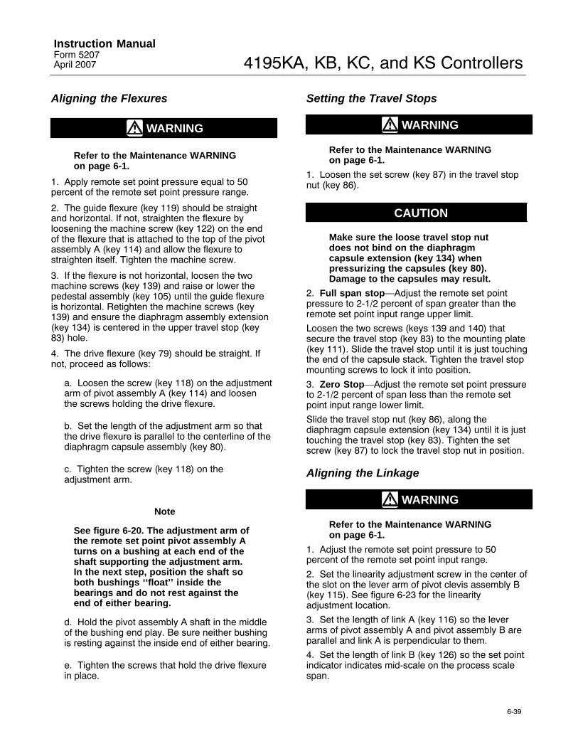
4195KA, KB, KC, and KS ControllersInstruction ManualForm 5207April 2007
6-39
Aligning the Flexures
WARNING
Refer to the Maintenance WARNINGon page 6-1.
1. Apply remote set point pressure equal to 50percent of the remote set point pressure range.
2. The guide flexure (key 119) should be straightand horizontal. If not, straighten the flexure byloosening the machine screw (key 122) on the endof the flexure that is attached to the top of the pivotassembly A (key 114) and allow the flexure tostraighten itself. Tighten the machine screw.
3. If the flexure is not horizontal, loosen the twomachine screws (key 139) and raise or lower thepedestal assembly (key 105) until the guide flexureis horizontal. Retighten the machine screws (key139) and ensure the diaphragm assembly extension(key 134) is centered in the upper travel stop (key83) hole.
4. The drive flexure (key 79) should be straight. Ifnot, proceed as follows:
a. Loosen the screw (key 118) on the adjustmentarm of pivot assembly A (key 114) and loosenthe screws holding the drive flexure.
b. Set the length of the adjustment arm so thatthe drive flexure is parallel to the centerline of thediaphragm capsule assembly (key 80).
c. Tighten the screw (key 118) on theadjustment arm.
Note
See figure 6-20. The adjustment arm ofthe remote set point pivot assembly Aturns on a bushing at each end of theshaft supporting the adjustment arm.In the next step, position the shaft soboth bushings ‘‘float’’ inside thebearings and do not rest against theend of either bearing.
d. Hold the pivot assembly A shaft in the middleof the bushing end play. Be sure neither bushingis resting against the inside end of either bearing.
e. Tighten the screws that hold the drive flexurein place.
Setting the Travel Stops
WARNING
Refer to the Maintenance WARNINGon page 6-1.
1. Loosen the set screw (key 87) in the travel stopnut (key 86).
CAUTION
Make sure the loose travel stop nutdoes not bind on the diaphragmcapsule extension (key 134) whenpressurizing the capsules (key 80).Damage to the capsules may result.
2. Full span stop�Adjust the remote set pointpressure to 2-1/2 percent of span greater than theremote set point input range upper limit.
Loosen the two screws (keys 139 and 140) thatsecure the travel stop (key 83) to the mounting plate(key 111). Slide the travel stop until it is just touchingthe end of the capsule stack. Tighten the travel stopmounting screws to lock it into position.
3. Zero Stop�Adjust the remote set point pressureto 2-1/2 percent of span less than the remote setpoint input range lower limit.
Slide the travel stop nut (key 86), along thediaphragm capsule extension (key 134) until it is justtouching the travel stop (key 83). Tighten the setscrew (key 87) to lock the travel stop nut in position.
Aligning the Linkage
WARNING
Refer to the Maintenance WARNINGon page 6-1.
1. Adjust the remote set point pressure to 50percent of the remote set point input range.
2. Set the linearity adjustment screw in the center ofthe slot on the lever arm of pivot clevis assembly B(key 115). See figure 6-23 for the linearityadjustment location.
3. Set the length of link A (key 116) so the leverarms of pivot assembly A and pivot assembly B areparallel and link A is perpendicular to them.
4. Set the length of link B (key 126) so the set pointindicator indicates mid-scale on the process scalespan.

4195KA, KB, KC, and KS ControllersInstruction Manual
Form 5207April 2007
6-40
5. Replace the tie bar (key 106) and install the twoscrews (key 103).
Remote Set Point Zero and SpanAdjustment
WARNING
Refer to the Maintenance WARNINGon page 6-1.
Note
For routine remote set point zero andspan calibration, refer to theappropriate procedures in Section 3,4, or 5. Use the following maintenanceremote set point zero and spanadjustment procedures only ifdifficulty is encountered with theroutine procedure or nonlinearityoccurs.
Refer to figures 6-19 and 6-23 for adjustmentlocations.
1. Decrease the remote set point pressure to 0percent of the remote set point input range.
2. The set point indicator should indicate the lowerlimit of the process scale span. If not, loosen theadjustment screw on link A (key 116), and adjust thelength so the set point indicator points to the lowerlimit of the process scale. Tighten the screw.
3. Make fine zero adjustments by loosening thezero adjustment locking screw (key 102) and turningthe zero adjustment screw (key 108). Tighten thelocking screw. Refer to figure 6-23 for the screwlocations.
4. Apply remote set point pressure equal to 100percent of the remote set point input range.
5. The set point indicator should indicate the upperlimit of the process scale span.
6. To increase the span, proceed as follows:
a. Turn the remote set point span adjustmentscrew clockwise.
b. To increase the span further than theadjustment screw allows, move both ends of linkA (key 116) to the right.
c. Make fine adjustments with the remote setpoint span adjustment screw.
7. To decrease the span, proceed as follows:
a. Turn the remote set point span adjustmentscrew counterclockwise.
b. To decrease the span further than theadjustment screw allows, move both ends of linkA (key 116) to the left.
c. Make fine adjustments with the remote setpoint span adjustment screw.
8. Repeat the adjustments until the upper and lowerindications are aligned with the upper and lowerlimits on the process scale.
9. Adjust the remote set point pressure for 50percent of the remote set point input range.
10. The set point indicator should indicate mid-scale±2 percent of the process scale span. If the error iswithin ±2 percent, proceed to step 11. If the error isgreater than ±2 percent of the scale span, proceedto the remote set point linearity adjustmentprocedure.
11. Adjust the set point indicator to mid-scale ±1percent of the process scale span by loosening thezero adjustment locking screw and turning the zeroadjustment screw. Tighten the locking screw.
12. Adjust the remote set point pressure to theupper and lower limits of the remote set point inputrange and make sure the set point indicator is stillwithin ±1 percent at the lower and upper limits of theprocess scale.
13. Perform the appropriate flapper alignmentprocedure and, if necessary, the process indicatorzero and span calibration procedure in Section 3, 4,or 5.

4195KA, KB, KC, and KS ControllersInstruction ManualForm 5207April 2007
6-41
Remote Set Point Linearity Adjustment
WARNING
Refer to the Maintenance WARNINGon page 6-1.
Adjust the linearity by loosening and repositioningthe linearity adjustment screw in the curved slot onthe lever arm of pivot assembly B (key 115).Adjusting the linearity affects the zero and spanadjustment.
1. Adjust the remote set point pressure to 50percent of the remote set point input range. The setpoint indicator should indicate mid-scale ±1 percentof the process scale span. If not, make fineadjustments by loosening the zero adjustmentlocking screw and turning the zero adjustmentscrew.
2. Adjust the remote set point pressure to 0 percentof the remote set point input range and note theindicator position relative to the process scale lowerlimit.
3. Adjust the remote set point pressure to 100percent of the remote set point input range and notethe indicator position relative to the process scaleupper limit.
4. If the greatest misalignment is positive (the setpoint indicator is to the right of the process scalelimits), loosen the linearity screw and move itclockwise in the slot. If the misalignment is negative,move the linearity screw counterclockwise in theslot.
5. If the misalignment is greater than 1 percent ofthe process scale span at the lower and upper limits,with one positive and the other negative, perform theremote set point zero and span adjustmentprocedure to correct a span error.
6. Repeat steps 1 through 4 until lower, middle, andupper indications are within ±1 percent of theprocess scale markings.
Auto/Manual Station (suffix letter E)Maintenance
Replacing the Auto/Manual Station
WARNING
Refer to the Maintenance WARNINGon page 6-1.
Refer to figures 7-1 and 7-7 for key numberlocations.
Note
This procedure also permitsreplacement of the switch manifoldO-rings (key 312), the auto/manualtubing assembly (key 138), and theframe gaskets (keys 4 and 5).
Disassembly
1. Remove the controller assembly from the caseby performing steps 1 through 3 of the case andcover replacement procedure.
2. Loosen the screw (key 316) that holds theauto/manual station (key 273) to the controllerframe.
3. Loosen the two screws (keys 314 and 315) thathold the auto/manual station to the auto/manualtubing assembly (key 138).
4. Remove the auto/manual station from thecontroller frame.
5. Remove the switch manifold O-rings (key 312).
6. Carefully loosen the nut on the relay nozzletubing assembly (key 18) where it connects to theauto/manual tubing assembly (key 138). Loosenthree screws (keys 34 and 131) and remove thetubing assembly and frame gaskets (keys 4 and 5).
7. Inspect the gaskets (keys 4 and 5) and O-rings(key 312) for wear. Replace if necessary.
Assembly
1. Install the gaskets and tubing assembly to theframe. Start, but do not tighten, the three screws(keys 34 and 131) and the nut on the relay nozzletubing assembly (key 18).
2. Install the switch manifold O-rings (key 312) andsecure the auto/manual station to the controllerframe with the screw (key 316) and to the tubingassembly (key 138) with the two screws (keys 314and 315). Do not tighten any screws.

4195KA, KB, KC, and KS ControllersInstruction Manual
Form 5207April 2007
6-42
CAUTION
In the next step, take care to tightenthe two screws (keys 314 and 315)evenly. Uneven tightening coulddamage the tubing assembly.
3. Position the auto/manual station as far down onthe frame and toward the scale as possible.Carefully tighten the two screws (keys 314 and 315)so that the auto/manual station contacts the threepads on the tubing assembly.
4. Carefully tighten the remaining screws and nuts.
5. Plug the controller output connection and applysupply pressure to the controller. Check for leaks.
6. Position the controller assembly in the case andstart, but do not tighten the nine mounting screws.Slide the controller assembly down to assure anO-ring seal at the pressure connections along thebottom of the case. Hold the controller assembly inplace while tightening the nine mounting screws.
7. Perform the appropriate calibration procedure inSection 3, 4, or 5.
Replacing the Switch Body Assembly,Lever O-Ring, Switch Body O-Ring, andTubing Assembly
WARNING
Refer to the Maintenance WARNINGon page 6-1.
Refer to figure 7-7 for key number location.
Disassembly
1. Remove the auto/manual station from thecontroller as described in steps 1 through 4 of thereplacing the auto/manual station procedure.
2. Loosen the two screws (key 288) and remove thelever cover plate (key 305).
WARNING
The lever spring (key 302) is underpreload. To avoid personal injury orlosing parts, carefully disassemble theauto/manual station.
3. Using a 1/16-inch (1.5 mm) punch, push thegroove pin (key 303) out toward the surface of thelever cover plate.
4. Remove the switch lever (key 304), lever spring(key 302), and lever spring seat (key 301).
5. Remove the tubing assembly (key 309).
WARNING
The switch body springs (key 295) areunder preload. To avoid personalinjury or losing parts, carefullyseparate the switch body assemblyfrom the loader assembly.
6. Loosen the two screws (key 290) and separatethe switch body assembly (key 291) from the loaderassembly (key 282).
7. Remove the O-rings (keys 292, 293, and 294),switch body springs (key 295), and balls (key 296).
8. Loosen two screws (key 308), and remove theclosing plate (key 307) and the closing plate gasket(key 306).
9. Pull the clip (key 300) from its engagement withthe lever assembly shaft (key 297).
10. Pull the lever assembly from the switch bodyassembly (key 291) and rocker (key 299).
11. Remove the O-ring (key 298).
12. Inspect the O-rings and gaskets for damage orwear; replace if necessary.
Assembly
1. Insert the lever assembly (key 297) into theswitch body assembly (key 291) and hold the rocker(key 299) with the flats on the lever assembly shaft.
2. Insert the clip (key 300) in the groove of the leverassembly shaft to hold the lever assembly (key 297)in the switch body assembly (key 291).
3. Position the closing plate gasket (key 306) andthe closing plate (key 307). Secure with two screws(key 308).
Note
After assembly in step 3, be sure theside of the closing plate marked OUTis visible.
4. Place the balls (key 296), switch body springs(key 295), and O-rings (keys 292, 293, and 294) inthe switch body assembly (key 291).

4195KA, KB, KC, and KS ControllersInstruction ManualForm 5207April 2007
6-43
Note
In the following step, the ends of thesprings must be in the counterboredspring seats before compression.
5. Compress the switch body springs with theloader assembly (key 282), and bolt the switch bodyassembly (key 291) to the loader assembly with thetwo screws (key 290).
6. Reconnect the tubing assembly (key 309).
7. Locate the lever spring (key 302) and the springseat (key 301) on the switch lever (key 304) andposition these parts in the opening of the loaderassembly (key 282).
8. Push the switch lever down, using the leverspring seat (key 301) and the lever assembly (key297) to preload the spring. Make sure the notch ofthe switch lever engages the pin of the leverassembly.
9. Drive in the groove pin (key 303) to hold theswitch lever.
10. Replace the lever cover plate (key 305) andattach with two screws (key 288).
11. Perform the assembly portion of the replacingthe auto/manual station procedure.
Replacing the Loader Range Spring,Diaphragm Assembly, Ball Seat, Tubing,and Ball
WARNING
Refer to the Maintenance WARNINGon page 6-1.
Refer to figure 7-7 for key number locations.
Disassembly
1. Remove the auto/manual station from thecontroller as described in steps 1 through 4 of thereplacing the auto/manual station procedure.
2. Remove the tubing assembly (key 309).
WARNING
To avoid personal injury caused bypreload from the range spring (key283), turn the loader knob (key 287)counterclockwise (opposite to the
arrow) to relieve pressure on thespring.
3. Loosen the four screws (key 289), and separatethe upper loader assembly (key 282) and the lowerloader assembly (key 274).
4. Remove the loader range spring (key 283), rangespring cup (key 284), and diaphragm assembly (key281).
5. Remove the tube (key 278), ball seats (key 280)and ball (key 279).
Assembly
1. Turn the loader knob (key 287) counterclockwiseto back the spring adjustment screw (key 285) allthe way out to eliminate loading the range spring.
2. Position the range spring cup (key 284), rangespring (key 283), and the diaphragm assembly (key281) on the upper loader assembly (key 282).
3. Position the ball (key 279), the tube (key 278),and the ball seats (key 280) between the ears of theloader assemblies (keys 282 and 274); position thediaphragm assembly (key 281) between the mainhalves of the loader assemblies.
Note
The tube (key 278) must be well seatedin the cups of the ball seats (key 280).
4. Bolt the loader assembly halves together usingthe four screws (key 289).
Note
Be sure that the supply and exhaustseats of the loader are correctlyaligned. Misalignment will impairloader performance.
5. Attach the tubing assembly (key 309).
6. Perform the assembly portion of the replacing theauto/manual station procedure.

4195KA, KB, KC, and KS ControllersInstruction Manual
Form 5207April 2007
6-44
Replacing the Loader Valve Plug andValve Plug Spring
WARNING
Refer to the Maintenance WARNINGon page 6-1.
Refer to figure 7-7 for key number location.
1. Remove the controller assembly from the caseby performing steps 1 through 3 of the case andcover replacement procedure.
2. Loosen the spring seat screw (key 275).
3. Remove the valve plug spring (key 276) and thevalve plug (key 277).
4. Inspect the parts and replace as necessary.
5. Install the valve plug spring and valve plug.
6. Tighten the spring seat screw.
7. Temporarily apply supply pressure and processpressure and check for leaks.
8. Position the controller assembly in the case andstart, but do not tighten the nine mounting screws.Slide the controller assembly down to assure anO-ring seal at the pressure connections along thebottom of the case. Hold the controller assembly inplace while tightening the nine mounting screws.
9. Mount the controller as described in theInstallation section.
10. Connect the external piping to the controller.

4195KA, KB, KC, and KS ControllersInstruction ManualForm 5207April 2007
7-1
Section 7 Parts
Parts OrderingWhenever corresponding with your EmersonProcess Management sales office about thisequipment, always mention the controller serialnumber. When ordering replacement parts, refer tothe 11-character part number of each required partas found in the following parts list.
WARNING
Use only genuine Fisher replacementparts. Components that are notsupplied by Emerson ProcessManagement should not, under anycircumstances, be used in any Fisherinstrument. Use of components notsupplied by Emerson will void yourwarranty, might adversely affect theperformance of the instrument, andcould give rise to personal injury andproperty damage.
Note
Neither Emerson, Emerson ProcessManagement, nor any of their affiliatedentities assumes responsibility for theselection, use, and maintenance ofany product. Responsibility for theselection, use, and maintenance ofany product remains with thepurchaser and end-user.
Parts KitsDescription Part Number
4190 Series Auto/Manual Repair KitContains keys 277, 278, 279, 281, 292,293, 294, 298, 306, 312 R4190X0AM12
4190 Series Auto/Manual Retrofit Kit, SST tubing,Contains keys 138, 273, 312, 313,314, 315, 316 R4190X00S12
4190 Series Case Handle KitContains lever and mounting hardware R4190X00H12
4190 Series Controller Repair KitContains keys 4, 5, 7, 8, 24, 52 R4190X00C12
4190 Series Pointer and Bracket Repair KitContains pointer and bracket ass�y,three machine screws, three washers R4190X00P12
Description Part Number
4190 Series Relay Replacement Kit Contains Relay Assembly (includes keys 13 and 15) and key 10
0.2 to 1.0 bar (3 to 15 psig) RRELAYX83C20.4 to 2.0 bar (6 to 30 psig) RRELAYX83D2
Type 4195KBF Anti-Reset Windup Retrofit Kit, SST tubing, Contains keys 44 and 55 R4190X00S22
Parts List
Abbreviations Used In Parts Listadj: adjustmentalt desgntn: alternative designationass�y: assemblyconn(s): connection(s)diff: differential (as in process differential
pressure)fdback: feedbackfill hd: fillister head (as in fillister head cap screw)ext: externalhd: head (as in machine screw head)int: internalOD: outside diameterp/o part of (as in part of another assembly)pl: plated (as in plated steel)pt: point (as in set point)qty: quantitySST: stainless steelw/: withw/o: without
Key Description Part Number
Controller Common Parts (figure 7-1)
Note
Figure 7-1 shows key numbers for the commonconstruction of all controller types. Figure 7-1continues over several pages. Be sure to check allpages of figure 7-1 to find the common keynumbers.
1 Case and cover ass�yFor use w/o remote set pt 46A5903X012For use w/remote set pt 46A5902X012
2 Nameplate, A91100 (aluminum) - - -3 Frame, A03600 (aluminum) 56A7001X0124* Frame gasket, chloroprene
For use between frame and framemanifold (key 135) 18A0749X012
5* Gasket, chloroprene4195KA, KB, and KS (1 req�d)4195KC (2 req�d) 18A0742X012
6 Machine screw, fill hd, 18−8 SST (9 req�d)2 req�d to mount the prop band ind coverto the frame
4 req�d to mount bellows bracket(key 31) to bellows beam (key 49)
2 req�d to attach process scalebrackets (keys 376, 377) to frame 1P4373X0012
*Recommended spare parts
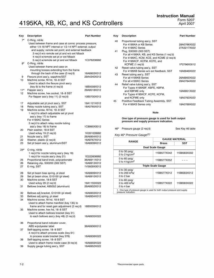
4195KA, KB, KC, and KS ControllersInstruction Manual
Form 5207April 2007
7-2
Key Description Part Number
7* O-Ring, nitrileUsed between frame and case at conns: process pressure,either 1/4-18 NPT internal or 1/2-14 NPT external; outputand supply; remote set point; and external feedback3 req�d w/o remote set pt and w/o ext fdback4 req�d w/remote set pt or ext fdback5 req�d w/remote set pt and ext fdback 1C376206992
8* O-Ring, nitrileUsed between frame and case onmounting bosses extending from the framethrough the back of the case (3 req�d) 16A6903X012
9 Flexure pivot ass�y, sapphire/SST 29A4340X01210 Machine screw, fill hd, 18−8 SST
Used to attach the flexure pivot ass�y(key 9) to the frame (4 req�d) 18B0008X012
11* Flapper ass�y 29A9518X01212 Machine screw, hex socket, 18−8 SST
For flapper ass�y (key 11) (2 req�d) 10B0700X012
17 Adjustable set pt pivot ass�y, SST 19A1121X01218 Relay nozzle tubing ass�y, SST 18A0765X01219 Machine screw, fill hd, 18−8 SST
1 req�d to attach adjustable set pt pivotass�y (key 17) to frame
For 4195KC Series3 req�d to attach relay nozzle tubing ass�y (key 18) to frame 1C8990X0012
20 Plain washer, 18-8 SSTUsed w/key 19 (2 req�d) 1K261028992
21 Nozzle ass�y, SST 26A6904X01222 Washer, plastic (2 req�d) 16A9767X01223 Set pt beam ass�y, aluminum/SST 16A6939X012
24* O-ring, nitrile1 req�d for nozzle tubing ass�y (key 18)1 req�d for nozzle ass�y (key 21) 1E222606992
25 Proportional band knob, polycarbonate 36A6911X01226 Retaining clip, S30200 (302 SST) 16A6913X01227 E-ring, SST 1V5929X0012
28 Set pt beam bias spring, pl steel 16A6909X01229 Set pt beam shoe, G10100 (pl steel) 16A6910X01230 Machine screw, 18-8 SST
Used w/key 29 (2 req�d) 19A1155X02231 Bellows bracket, A95052 (aluminum) 26A6932X012
32 Bellows adj bracket, G10100 (pl steel) 16A6933X01233 Bellows adj spring, pl steel 16A6934X01234 Machine screw, fill hd, 18-8 SST
Used to attach frame manifold (key 135) toframe and for reset gain adjustment (2 req�d) 18B0009X012
35 Machine screw, hex hd, 18−8 SSTUsed to attach bellows bracket (key 31)to each bellows ass�y (key 48) (2 req�d) 16A6935X022
36 Proportional band indicator cover,ABS w/polyester label 36A6936X012
37 Self-tapping screw, 18−8 SST4 req�d to attach process scale (key 61)to process scale bracket (key 376) 16A6938X022
38 Self-tapping screw, 18−8 SSTUsed to attach frame inside case (9 req�d) 16A6959X022
39 Supply gauge tubing ass�y, SST 16A6952X022
Key Description Part Number
40 Proportional tubing ass�y, SSTFor 4195KA or KB Series 28A0766X022For 4195KC Series 27A3217X022
41 Plug, S30300 (303 SST)For all 4195KA, KB, and KS Series (1 req�d)For 4195KC, KCM, KCE, and KCME (2 req�d)For 4195KCF, KCFM, KCFE, and KCFME (1 req�d) 1P2796X0012
42 Reset valve tubing ass�y, SSTFor 4195KB Series w/o ext feedback, SST 16A6949X022
43 Reset tubing ass�y, SSTFor all 4195KB Series 26A6950X022For all 4195KC Series 28A0764X022
44 Relief valve tubing ass�y, SSTFor Types 4195KBF, KBFE, KBFM,and KBFME only 16A6951X022
For Types 4195KCF, KCFE, KCFM,and KCFME only 18A0763X022
45 Posititve Feedback Tubing Assembly, SSTFor 4195KS Series only 18A0769X022
Note
One type of pressure gauge is used for both outputpressure and supply pressure indication.
46* Pressure gauge (2 req�d) See Key 46 table
Key 46* Pressure Gauge(1)
RANGEGAUGE MATERIAL
Brass SST
Dual Scale Gauge
0 to 30 psig/0 to 2 kg/cm2 11B8577X042 11B8583X032
0 to 60 psig/0 to 4 kg/cm2 11B8577X052 − − −
Triple Scale Gauge
0 to 30 psig/0 to 200 kPa/0 to 2 bar
11B8577X012 11B8583X012
0 to 60 psig/0 to 400 kPa/0 to 4 bar
11B8577X022 11B8583X022
1. One type of pressure gauge is used for both output pressure and supplypressure indication.
*Recommended spare parts

4195KA, KB, KC, and KS ControllersInstruction ManualForm 5207April 2007
7-3
Key Description Part Number
48* Bellows ass�y (2 req�d)Brass 16A6953X012SST 16A6953X022
49 Bellows beam, A96061 (aluminum)0.2 to 1.0 bar (3 to 15 psig) 16A6957X0120.4 to 2.0 bar (6 to 30 psig) 16A6958X012
51 Relief valve cover plate, A03600 (aluminum) 2V59730801252* O-ring, nitrile 1C853806992
Used w/key 51 (2 req�d)53 Machine screw, fill hd, 18−8 SST
Used w/key 51 (2 req�d)4195KA, KB, and KS Series4195KC Series (7 req�d) 1U8842X0012
54 Reset restriction valve (4195KB Series only) 19A4361X03255 Differential relief valve
For all 4195KB and KC Series w/suffixletter F, anti-reset windup 21A6447X0A2
Key Description Part Number
56 Process and set pt indicator ass�y w/sensing element
The part numbers in the Key 56 tables are for the completeprocess and set pt indicator ass�y with a process sensingelement. Individual indicator ass�y parts are listed in twosubsections of this parts list: the Process and Set PointIndicator Assembly (key 56) subsection and the IndicatorAssembly (key 101) subsection. Key numbers for individualindicator parts also appear in figures 7-2 and 7-3.
Process and set pt indicator ass�yw/Bourdon tube sensing element See Key 56 tables
Process and set pt indicator ass�yw/capsular element ass�y See Key 56 tables
Key 56 Process and Set Point Indicator Assembly with Bourdon TubeBAR RANGE PSIG RANGE ASSEMBLY PART NUMBER
W/O Remote Set Point W/Remote Set Point
With S31600 (316 SST) Bourdon Tube
0 to 1.6 or 0 to 20 to 4 or 0 to 2.50 to 60 to 10
0 to 300 to 600 to 1000 to 200
32B1532X01232B1532X02232B1532X03232B1532X042
32B1532X14232B1532X15232B1532X16232B1532X172
0 to 160 to 40 or 0 to 250 to 600 to 100
0 to 3000 to 6000 to 10000 to 1500
32B1532X05232B1532X06232B1532X07232B1532X082
32B1532X18232B1532X19232B1532X20232B1532X212
0 to 1600 to 250 or 0 to 300
0 to 30000 to 5000
32B1532X09232B1532X102
32B1532X22232B1532X232
Key 56 Process and Set Point Indicator Assembly with Capsular Element Assembly
RANGE
ASSEMBLY PART NUMBER
W/O Remote Set Point W/Remote Set Point
N09902 N09902
Positive and Compound Element
U.S. Units
0 to 60 inch wc0 to 5 psig 0 to 10 Psig 0 to 12 Psig 0 to 15 Psig 0 to 20 Psig 0 to 24 Psig 0 to 30 Psig
36A6986X08236A6986X09236A6986X10236A6986X11236A6986X30236A6986X12236A6986X13236A6986X142
36A6986X22236A6986X23236A6986X24236A6986X25236A6986X32236A6986X26236A6986X27236A6986X282
Vacuum Element
U.S. Units
−5 to 0 Inch Hg−10 to 0 Inch Hg−20 to 0 Inch Hg−30 to 0 Inch Hg
36A6987X05236A6987X06236A6987X07236A6987X082
36A6987X13236A6987X14236A6987X15236A6987X162
*Recommended spare parts
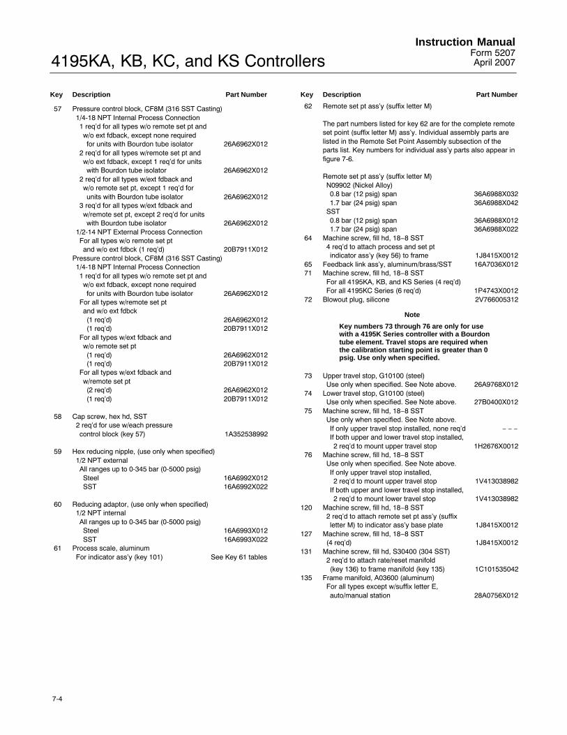
4195KA, KB, KC, and KS ControllersInstruction Manual
Form 5207April 2007
7-4
Key Description Part Number
57 Pressure control block, CF8M (316 SST Casting)1/4-18 NPT Internal Process Connection1 req�d for all types w/o remote set pt andw/o ext fdback, except none requiredfor units with Bourdon tube isolator 26A6962X012
2 req�d for all types w/remote set pt andw/o ext fdback, except 1 req�d for unitswith Bourdon tube isolator 26A6962X012
2 req�d for all types w/ext fdback andw/o remote set pt, except 1 req�d forunits with Bourdon tube isolator 26A6962X012
3 req�d for all types w/ext fdback andw/remote set pt, except 2 req�d for unitswith Bourdon tube isolator 26A6962X012
1/2-14 NPT External Process ConnectionFor all types w/o remote set ptand w/o ext fdbck (1 req�d) 20B7911X012
Pressure control block, CF8M (316 SST Casting)1/4-18 NPT Internal Process Connection1 req�d for all types w/o remote set pt andw/o ext fdback, except none requiredfor units with Bourdon tube isolator 26A6962X012
For all types w/remote set ptand w/o ext fdbck(1 req�d) 26A6962X012(1 req�d) 20B7911X012
For all types w/ext fdback andw/o remote set pt(1 req�d) 26A6962X012(1 req�d) 20B7911X012
For all types w/ext fdback andw/remote set pt(2 req�d) 26A6962X012(1 req�d) 20B7911X012
58 Cap screw, hex hd, SST2 req�d for use w/each pressurecontrol block (key 57) 1A352538992
59 Hex reducing nipple, (use only when specified)1/2 NPT externalAll ranges up to 0-345 bar (0-5000 psig)Steel 16A6992X012SST 16A6992X022
60 Reducing adaptor, (use only when specified)1/2 NPT internalAll ranges up to 0-345 bar (0-5000 psig)Steel 16A6993X012SST 16A6993X022
61 Process scale, aluminumFor indicator ass�y (key 101) See Key 61 tables
Key Description Part Number
62 Remote set pt ass�y (suffix letter M)
The part numbers listed for key 62 are for the complete remoteset point (suffix letter M) ass�y. Individual assembly parts arelisted in the Remote Set Point Assembly subsection of theparts list. Key numbers for individual ass�y parts also appear infigure 7-6.
Remote set pt ass�y (suffix letter M)N09902 (Nickel Alloy)0.8 bar (12 psig) span 36A6988X0321.7 bar (24 psig) span 36A6988X042
SST0.8 bar (12 psig) span 36A6988X0121.7 bar (24 psig) span 36A6988X022
64 Machine screw, fill hd, 18−8 SST4 req�d to attach process and set ptindicator ass�y (key 56) to frame 1J8415X0012
65 Feedback link ass�y, aluminum/brass/SST 16A7036X01271 Machine screw, fill hd, 18−8 SST
For all 4195KA, KB, and KS Series (4 req�d)For all 4195KC Series (6 req�d) 1P4743X0012
72 Blowout plug, silicone 2V766005312
Note
Key numbers 73 through 76 are only for usewith a 4195K Series controller with a Bourdontube element. Travel stops are required whenthe calibration starting point is greater than 0psig. Use only when specified.
73 Upper travel stop, G10100 (steel)Use only when specified. See Note above. 26A9768X012
74 Lower travel stop, G10100 (steel)Use only when specified. See Note above. 27B0400X012
75 Machine screw, fill hd, 18−8 SSTUse only when specified. See Note above.If only upper travel stop installed, none req�d − − −If both upper and lower travel stop installed,2 req�d to mount upper travel stop 1H2676X0012
76 Machine screw, fill hd, 18−8 SSTUse only when specified. See Note above.If only upper travel stop installed,2 req�d to mount upper travel stop 1V413038982
If both upper and lower travel stop installed,2 req�d to mount lower travel stop 1V413038982
120 Machine screw, fill hd, 18−8 SST2 req�d to attach remote set pt ass�y (suffixletter M) to indicator ass�y base plate 1J8415X0012
127 Machine screw, fill hd, 18−8 SST(4 req�d) 1J8415X0012
131 Machine screw, fill hd, S30400 (304 SST)2 req�d to attach rate/reset manifold(key 136) to frame manifold (key 135) 1C101535042
135 Frame manifold, A03600 (aluminum)For all types except w/suffix letter E,auto/manual station 28A0756X012

4195KA, KB, KC, and KS ControllersInstruction ManualForm 5207April 2007
7-5
Key 61 Process Scale, Positive PressureScale Range Part Number
Bar Scales
0 to 150 mbar0 to 400 mbar0 to 0.60 to 1
1R0003X15621R0003X04221R0003X04021R0003X0432
0.2 to 10 to 1.40 to 1.60 to 20.4 to 2
1R0003X16021R0003X16121R0003X04421R0003X16521R0003X1622
0 to 2.50 to 40 to 60 to 100 to 16
1R0003X04521R0003X04621R0003X04721R0003X04821R0003X0492
0 to 250 to 400 to 600 to 1000 to 160
1R0003X05721R0003X05021R0003X05121R0003X05221R0003X0532
0 to 250 1R0003X0542
Psig Scales
0 to 60 inch wc0 to 50 to 103 to 150 to 15
1R0003X02021R0003X02121R0003X02221R0003X01721R0003X0232
0 to 206 to 300 to 300 to 600 to 100
1R0003X02421R0003X01821R0003X00321R0003X00421R0003X0052
0 to 2000 to 3000 to 6000 to 10000 to 1500
1R0003X00621R0003X00721R0003X00821R0003X00921R0003X0102
0 to 30000 to 5000
1R0003X01121R0003X0122
kPa Scales
0 to 2000 to 4000 to 7000 to 14000 to 2000
1R0003X09221R0003X09321R0003X09421R0003X07021R0003X0952
0 to 40000 to 70000 to 10,0000 to 20,0000 to 35,000
1R0003X09621R0003X09721R0003X07121R0003X09821R0003X0992
Key 61 Process Scale, All ControllersScale Range Part Number
0 to 100%0 to 10 Square Root0 to 100 Square Root
1R0003X10421R0003X11721R0003X1292
Key 61 Process Scale, Vacuum and Compound PressureSCALE RANGE PART
NUMBERVacuum Pressure
Bar Scales
150 to 0 mbar400 to 0 mbar0.6 to 01 to 0
1R0003X16321R0003X05921R0003X06021R0003X0612
In Scales
5 to 010 to 020 to 030 to 0
1R0003X03221R0003X03321R0003X03421R0003X0192
Compound Pressure
Bar Scales
−50 to +100 mbar−150 to +250 mbar−0.2 to +0.4−0.4 to +0.6−0.6 to +0.8−1 to +0.6−1 to +1
1R0003X15721R0003X06321R0003X06421R0003X06521R0003X15821R0003X06621R0003X1592
Psig Scales
30 inches wc vac. to 30 inches wc5 inches Hg vac. to 2.5 psig10 inches Hg vac. to 5 psig15 inches Hg vac. to 7.5 psig20 inches Hg vac. to 10 psig30 inches Hg vac. to 15 psig
1R0003X02521R0003X03521R0003X03621R0003X02621R0003X03721R0003X0272
Key Description Part Number
136 Rate/reset manifold, A03600 (aluminum)For all types except 4195KC Series 28A0747X012
137 Rate tubing ass�y (for 4195KC Series only)SST/aluminum 28A0762X042
138 Auto/manual tubing ass�yUse w/suffix letter E, auto/manual station onlySST/aluminum 38A2859X022
140 Machine screw, fill hd, 18−8 SSTUsed to attach remote set pt ass�y (suffixletter M) to indicator ass�y (key 56) 16A7007X022
162 Machine screw, hex hd, 18−8 SSTUsed to attach the reset valve (4195KB Series)or rate/reset valve (4195KC Series) to the frameFor 4195KB and KC Series only 1B8480X0012
262 Rate/reset valve ass�y (for 4195KC Series only)Brass bellows0.2 to 1.0 bar (3 to 15 psig) 39A6013X0520.4 to 2.0 bar (6 to 30 psig) 39A6013X072
SST bellows0.2 to 1.0 bar (3 to 15 psig) 39A6013X0620.4 to 2.0 bar (6 to 30 psig) 39A6013X082
273 Auto/manual station (suffix letter E) 48A2905X012
The part number listed for key 273 is for the completeauto/manual station (suffix letter E). Individual ass�y parts arelisted in the Auto/Manual Station subsection of the parts list.Key numbers for individual ass�y parts also appear in figure7-7.
310 Lithium grease (not furnished with controller)311 Anti-seize sealant (not furnished with controller)
312* O-ring, nitrileFor all types w/suffix letter E,auto/manual station (3 req�d) 1P8453X0022
*Recommended spare parts

4195KA, KB, KC, and KS ControllersInstruction Manual
Form 5207April 2007
7-6
SECTION D-D
SEE VIEW H SEE VIEW G B
B
SEE VIEW LC
C
DD
K
K
SEE VIEW M
SEE VIEW E
SECTION B-B
VIEW C-C 4195KA SERIES
APPLY LUB/ SEALANT56A9752-U SHT 1 and 2 / DOC
VIEW C-C 4195KS SERIES
Figure 7-1. Controller Assembly Drawings
Key Description Part Number
313 Auto/Manual Scale, plasticFor all types w/suffix letter E,auto/manual station 38A2901X012
314 Machine screw, fill hd, 18−8 SSTFor all types w/suffix letter E,auto/manual station 1C101535042
315 Machine screw, fill hd, 18−8 SSTFor all types w/suffix letter E,auto/manual station 1B9925X0012
Key Description Part Number
316 Machine screw, SSTFor all types w/suffix letter E,auto/manual station 1U8841X0012
317 Silicone based lubricant, (not furnished with controller)318 Lubricant, silicone, not furnished with controller)339 External feedback ass�y, SST tubing
For controllers w/Bourdon tube orvacuum capsule 28A7285X022
For controllers w/positive or w/compound capsules 29A5715X022
362 Spring retaining washer, SST 1B196138992365 Washer, 18−8 SST 11B6501X012

4195KA, KB, KC, and KS ControllersInstruction ManualForm 5207April 2007
7-7
F F F F
VIEW F-F VIEW F-F
VIEW E4195KB SERIES
VIEW E4195KB SERIES WITHANTI-RESET WINDUP(SUFFIX LETTER F)
VIEW C-C4195KB SERIES
VIEW C-C4195KB SERIES WITHANTI-RESET WINDUP(SUFFIX LETTER F)
56A9752-U SHT 2 / DOC
VIEW K-KPROCESS CONNECTION
ADAPTORS
56A9752-U SHT 4 / DOC
Figure 7-1. Controller Assembly Drawings (cont’d)

4195KA, KB, KC, and KS ControllersInstruction Manual
Form 5207April 2007
7-8
VIEW F-F
VIEW F-F
VIEW E 4195KC SERIES
VIEW E 4195KC SERIES WITHANTI-RESET WINDUP (SUFFIX LETTER F)
VIEW C-C 4195KC SERIES VIEW C-C 4195KC SERIES WITHANTI-RESET WINDUP(SUFFIX LETTER F)
F F
F F
56A9752-U SHT 3 / DOC
Figure 7-1. Controller Assembly Drawings (cont’d)

4195KA, KB, KC, and KS ControllersInstruction ManualForm 5207April 2007
7-9
SECTION B-B4195KA SERIES
SECTION B-B4195KB SERIES
SECTION B-B4195KC SERIES
56A9752-U SHT 2 / DOC56A9752-U SHT 3 / DOC
VIEW LCONTROLLERS WITH AUTO/MANUAL STATION
(SUFFIX LETTER E)
56A9752-U SHT 4 / DOC
VIEW B-B 4195KS SERIES
56A9752-U SHT 2 / DOC
Figure 7-1. Controller Assembly Drawings (cont’d)
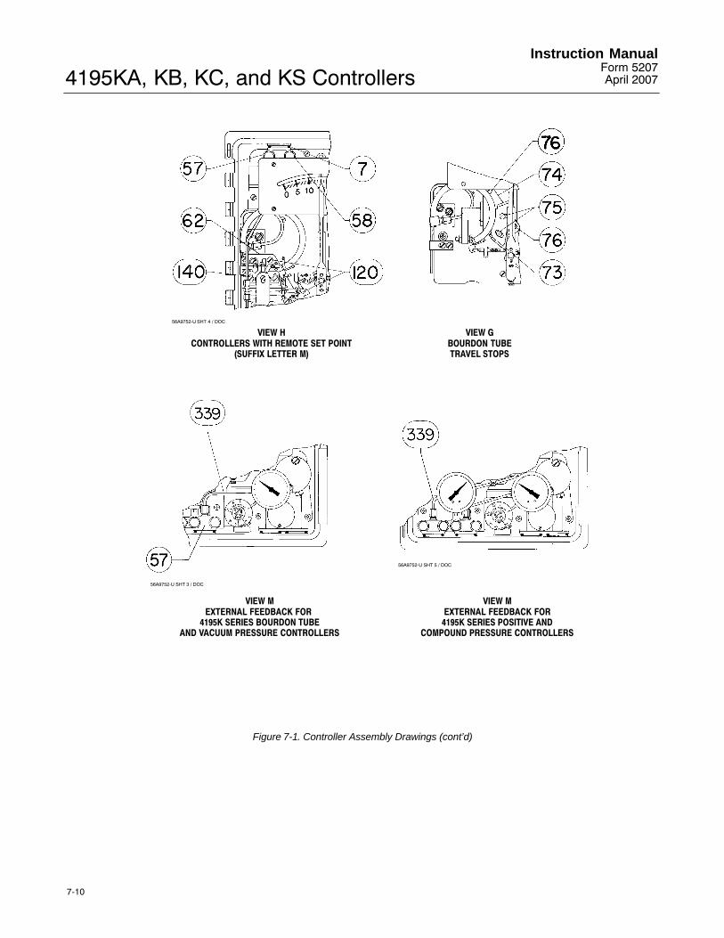
4195KA, KB, KC, and KS ControllersInstruction Manual
Form 5207April 2007
7-10
56A9752-U SHT 4 / DOC
56A9752-U SHT 3 / DOC
56A9752-U SHT 5 / DOC
VIEW HCONTROLLERS WITH REMOTE SET POINT
(SUFFIX LETTER M)
VIEW GBOURDON TUBETRAVEL STOPS
VIEW MEXTERNAL FEEDBACK FOR
4195K SERIES BOURDON TUBEAND VACUUM PRESSURE CONTROLLERS
VIEW MEXTERNAL FEEDBACK FOR
4195K SERIES POSITIVE ANDCOMPOUND PRESSURE CONTROLLERS
Figure 7-1. Controller Assembly Drawings (cont’d)

4195KA, KB, KC, and KS ControllersInstruction ManualForm 5207April 2007
7-11
32B1532-A / DOC
Figure 7-2. Process and Set Point Indicator Assembly for Bourdon Tube Controllers
Process and Set Point IndicatorAssembly (key 56) (figures 7-2 and 7-3)Key Description Part Number
With capsular element ass’y
101 Indicator ass�y
The part numbers listed here for key 101 are for the indicatorass�y only. Individual part numbers are listed in the IndicatorAssembly and the Capsular Element Assembly subsections ofthis parts list. Key numbers for individual ass�y parts alsoappear in figures 7-4 and 7-5.
For use w/o remote set pt 39A1126X012For use w/remote set pt 39A1126X022
113 Capsular element ass�y See Key 113 table
The part numbers listed in the key 113 table are for thecomplete capsular element ass�y. Individual ass�y parts arelisted in the Capsular Element Assembly subsection of thisparts list. Key numbers for individual ass�y parts also appear infigure 7-4.
Key Description Part Number
127 Machine screw, fill hd, 18−8 SST4 req�d to attach the capsular element ass�y to the indicator ass�y (key 101) 1J8415X0012
With Bourdon tube
101 Indicator ass�y
The part numbers listed here for key 101 are for the indicatorass�y only. Individual part numbers are listed in the IndicatorAssembly subsection of this parts list. Key numbers forindividual ass�y parts also appear in figure 7-4.
For use w/o remote set pt 39A1126X012For use w/remote set pt 39A1126X022
379 Process Tube Retainer, S30400 (304 SST) 18A8870X012380 Machine screw, pan hd, 18−8 SST 1H2674X0012381 Process tubing ass�y, SST 12B4951X012382 Link ass�y, steel/SST 22B0469X012383* Bourdon tube See Key 383 table384 Screw, self-tapping, pl steel (2 req�d) 16A9772X022
*Recommended spare parts
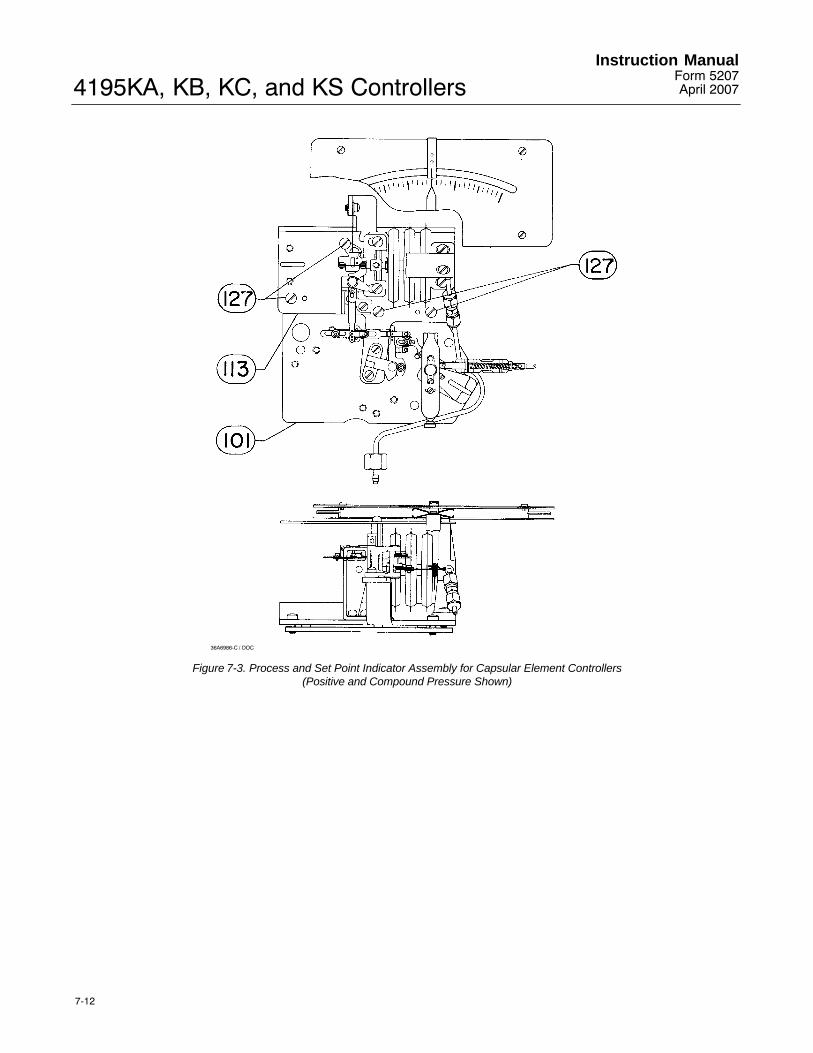
4195KA, KB, KC, and KS ControllersInstruction Manual
Form 5207April 2007
7-12
36A6986-C / DOC
Figure 7-3. Process and Set Point Indicator Assembly for Capsular Element Controllers(Positive and Compound Pressure Shown)

4195KA, KB, KC, and KS ControllersInstruction ManualForm 5207April 2007
7-13
Key 113 Capsular Element Assembly(1)
PRESSURE RANGEMATERIAL
N09902
Positive
0 to 60 inch wc0 to 5 psig0 to 10 psig3 to 15 psig
58A0708X08258A0708X09258A0708X10258A0708X112
0 to 15 psig0 to 20 psig6 to 30 psig0 to 30 psig
58A0508X15258A0708X12258A0708X13258A0708X142
Vacuum
−5 to 0 inch Hg−10 to 0 inch Hg−20 to 0 inch Hg−30 to 0 inch Hg
58A0710X05258A0710X06258A0710X07258A0710X082
Compound
−30 to 30 inch wc−5 inch Hg to 2.5 psig−10 inch Hg to 5 psig
58A0708X17258A0708X18258A0708X192
−15 inch Hg to 7.5 psig−20 inch Hg to 10 psig−30 inch Hg to 15 psig
58A0708X20258A0708X27258A0708X222
1. For information on scale compatibility, consult your Emerson Process Management sales office. Capsular Element Assembly may be ordered as part of the Process/SetpointIndicator Assembly (key 56) or ordered separately. See Capsular Element Assembly section for available replacement parts.
Key 383* Bourdon TubesBAR RANGE PSIG RANGE PART NUMBER
S31600 (316 SST) Bourdon Tube
0 to 1.6 or 0 to 20 to 4 or 0 to 2.50 to 60 to 10
0 to 300 to 600 to 1000 to 200
32B4589X01232B4589X02232B4589X03232B4589X042
0 to 160 to 40 or 0 to 250 to 600 to 100
0 to 3000 to 6000 to 10000 to 1500
32B4589X05232B4589X06232B4589X07232B4589X082
0 to 1600 to 250 or 0 to 300
0 to 30000 to 5000
32B4589X09232B4589X102
*Recommended spare parts

4195KA, KB, KC, and KS ControllersInstruction Manual
Form 5207April 2007
7-14
39A1126-H / DOC
Figure 7-4. Indicator Assembly
Indicator Assembly (key 101) (figure 7-4)
Key Description Part Number
Note
Key numbers 37, 61, 376, 377, and 378 are notincluded as part of the indicator assembly (key101). If replacing the indicator assembly andthese parts are required, order themseparately.
37 Self-tapping screw, 18−8 SST4 req�d to attach process scale (key 61)to process scale bracket (key 376) 16A6938X022
61 Process scale, aluminum See Key 61 table353 Machine screw, pan hd, 18−8 SST
(4 req�d) 16A7044X022366 Controller Mounting Plate, 18−8 SST 38A1735X012
367 Support bracket ass�y, zinc/brass 16A7013X012368 Link ass�y, 18−8 SST (2 req�d) 16A7039X012369 Process pointer adj ass�y,
aluminum/SST/brass 28A1736X012370 Set pt pointer ass�y
aluminum/SST/brass 26A9750X012
371 Pivot pin, S30200 (302 SST) (2 req�d) 16A7027X012372 Washer, plain, 18−8 SST
(4 req�d) 1V7657X0012374 Pointer and bracket ass�y
aluminum/steel 26A7059X012
Key Description Part Number
375 Set pt indicator ass�y, A93003 (aluminum)For controllers w/remote set pt 31B2241X012For controllers w/o remote set pt 26A7045X012
376 Dial Bracket, G10080 (steel) 36A7050X012377 Dial bracket, G10080 (steel) 36A7051X012378 Screw, self-tapping, 18−8 SST
(2 req�d) 16A9772X022
Capsular Element Assembly (key 113)(figure 7-5)12 Cap screw, hex socket, 18−8 SST
(2 req�d) 1U62133298213 Plain washer, 18−8 SST
(2 req�d) 61000310X1277 Mounting plate, G10100 (pl steel) 38A0667X01278 Long pivot clevis ass�y, plastic/SST 26A9784X01279 Drive flexure, S30200 (302 SST) 16A9794X01280 Diaphragm capsule ass�y See Key 80 table81 Pedestal assembly, SST 18A0670X01282 Diaphragm ass�y extension, A96061 (aluminum)
See key 80 table to determine if required 18A0698X01283 Travel stop, CF8 (SST casting) 16A9797X01284 Drive bracket ass�y, SST 16A9798X01286 Travel stop nut, S30300 (303 SST)
See key 80 table for quantity 16A9799X01287 Set screw, 18−8 SST
1 req�d for drive bracket ass�y (key 84), 1J8406X00121 req�d for each travel stop nut (key 86) 1J8406X0012
88 Connecting link ass�y,aluminum/bronze/brass 10B8448X012
89 Short pivot clevis ass�y, plastic/SST 16A9791X012
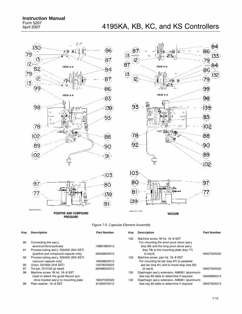
4195KA, KB, KC, and KS ControllersInstruction ManualForm 5207April 2007
7-15
VIEW A-A
VIEW A-A
VIEW A-A
VIEW A-A
58A0708-E/DOC58A0710-C / DOC
POSITIVE AND COMPOUNDPRESSURE
VACUUM
Figure 7-5. Capsular Element Assembly
Key Description Part Number
90 Connecting link ass�y,aluminum/bronze/brass 10B8769X012
91 Process tubing ass�y, S30400 (304 SST)(positive and compound capsule only) 28A0682X012
92 Process tubing ass�y, S30400 (304 SST)(vacuum capsule only) 18A0683X012
93 Union, S31600 (316 SST) 1A5782X002297 Tie bar, G10100 (pl steel) 26A9803X01298 Machine screw, fill hd, 18−8 SST
Used to attach the guide flexure (p/odrive bracket ass�y) to mounting plate 18A0703X022
99 Plain washer, 18−8 SST 61000370X12
Key Description Part Number
102 Machine screw, fill hd, 18−8 SSTFor mounting the short pivot clevix ass�y(key 89) and the long pivot clevis ass�y(key 78) to the mounting plate (key 77)(4 req�d) 18A0703X022
103 Machine screw, pan hd, 18−8 SSTFor mounting tie bar (key 97) to pedestalass�ies (key 81) and to travel stop (key 83)(2 req�d) 18A0703X022
130 Diaphragm ass�y extension, A96061 (aluminum)See key 80 table to determine if required 18A0699X012
132 Diaphragm ass�y extension, A96061 (aluminum)See key 80 table to determine if required 18A0700X012

4195KA, KB, KC, and KS ControllersInstruction Manual
Form 5207April 2007
7-16
Key 80 Capsular Element Assembly, Travel Stop (key 86) and Diaphragm Assembly Extension
RANGE
CAPSULAR ELEMENT MATERIAL
N09902
CapsularElement(key 80)
Part Number
Number ofTravel Stops
(key 86)Required
DiaphragmAssemblyExtensionRequired
Positive and Compound Element
Metric units
0 to 150 mbar0 to 400 mbar0 to 0.6 bar0 to 1 bar and 0.2 to 1 bar0 to 1.4 bar0 to 1.6 bar and 0 to 2 bar0.4 to 2 bar
26A9773X01226A9775X01226A9775X01226A9776X03226A9777X01226A9779X01226A9778X022
1222212
key 82key 130key 130key 130key 130key 82key 130
U. S. units
0 to 60 inch wc0 to 5 psig0 to 10 psig0 to 15 psig and 3 to 15 psig0 to 20 psig6 to 30 psig0 to 30 psig
26A9773X01226A9774X01226A9775X01226A9776X03226A9777X01226A9778X02226A9779X012
1122221
key 82key 82key 130key 130key 130key 130key 82
Vacuum Element
Metric units−150 to 0 mbar−400 to 0 mbar and 0.6 to 0 bar−1 to 0 bar
26A9773X01226A9775X01226A9776X032
222
key 132key 133key 133
U. S. units
−5 to 0 inch Hg−10 to 0 inch Hg−20 to 0 inch Hg−30 to 0 inch Hg
26A9773X01226A9774X01226A9775X01226A9776X032
2222
key 132key 132key 133key 133
Key Description Part Number
133 Diaphragm ass�y extension, A96061 (aluminum)See key 80 table to determine if required 18A0701X012
139 Machine screw, fill hd, 18−8 SST2 req�d to mount each pedestal ass�y (key 81)(4 req�d) 1J8415 X0012
Relay (figure 6-2)Relay Assembly (includes keys 13 and 15)
0.2 to 1.0 bar (3 to 15 psig) 32B0257X0C20.4 to 2.0 bar (6 to 30 psig) 32B0257X0D2
10 Relay mounting screw, 18−8 SST(2 req�d) 1U901238982
13* O-ring, nitrile 17A6891X01215* O-ring, nitrile (2 req�d) 1D687506992
Note
The above relay parts are included in the 4190Series Relay Replacement Kit.
Remote Set Point Assembly (suffix letterM) (key 62) (figure 7-6)12 Cap screw, hex socket, 18−8 SST
(2 req�d) 1U62133298213 Plain washer, 18−8 SST (3 req�d) 61000310X1279 Drive flexure, SST 16A9794X012
Key Description Part Number
80 Diaphragm capsule ass�y1 bar (12 psig) spanN09902 (Nickel Alloy) 26A9776X032SST 28A2848X022
2 bar (24 psig) spanN09902 (Nickel Alloy) 26A9778X022SST 28A2850X022
83 Travel stop, CF8 (SST casting) 16A9797X01286 Travel stop nut, S30300 (303 SST) 16A9799X01287 Set screw, hex socket, 18−8 SST 1J8406X001293 Union, S31600 (316 SST) 1A5782X002299 Plain washer, 18−8 SST 61000370X12
102 Machine screw, fill hd, 18−8 SST(4 req�d) 18A0703X022
103 Machine screw, pan hd, 18−8 SST(2 req�d) 18A0703X022
104 Remote set pt tubing ass�y,S30400 (304 SST) 28A0697X012
105 Pedestal ass�y, SST 18A0669X022106 Tie bar, G10100 (pl steel) 16A9789X022107 Spring, pl steel 18A0704X012108 Zero adj screw, S30300 (303 SST) 18A1737X022109 Pivot screw, S30300 (303 SST) 18A1738X022110 Zero adj bracket, S30400 (304 SST) 28A0661X012
*Recommended spare parts

4195KA, KB, KC, and KS ControllersInstruction ManualForm 5207April 2007
7-17
APPLY LUB / SEALANT36A6988-C / DOC
Figure 7-6. Remote Set Point Assembly
Key Description Part Number
111 Mounting plate, G10100 (pl steel) 38A0668X012112 Spring washer, pl steel 17A2700X012114 Pivot clevis ass�y A, plastic/SST 18A0658X012115 Pivot clevis ass�y B, plastic/SST 16A9808X012116 Connecting link ass�y,
aluminum/bronze/brass 18A0666X012
118 Cap screw, hex socket, 18−8 SST 1U621332982119 Guide flexure, S30200 (302 SST) 18A0660X012121 Drive bracket, S30400 (304 SST) 28A0662X012122 Machine screw, fill hd, 18−8 SST
(2 req�d) 1U3737X0012123 Plain washer, 18−8 SST 1P752438982124 Nut, Hex, 18−8 SST 60000410X12125 Spacer, A92011 (aluminum) 18A0702X012126 Connecting link ass�y,
aluminum/bronze/brass 18A0676X012
134 Diaphragm ass�y extension, A92011 (aluminum) 18A1739X012139 Machine screw, fill hd, 18−8 SST
(3 req�d) 1J8415X0012141 Adj arm, S30400 (304 SST) 28A0663X012311 Anti-seize sealant (not furnished with controller)
Auto/Manual Station (suffix letter E)(figure 7-7)274 Lower loader ass�y, aluminum 18A2892X012275 Spring seat screw, pl steel 18A2876X012276 Valve plug spring, K08500 (pl steel) 18A2877X012277 Valve plug, 18−8 SST 18A2878X012278 Tube, plastic 18A2880X012279 Ball, SST 18A2902X012280 Ball seat, nitrile (2 req�d) 18A2881X012281 Diaphragm ass�y, nitrile/aluminum 18A2884X012282 Loader ass�y, aluminum/plastic 18A2893X012283 Range spring, SST 18A2885X012284 Range spring cup, pl steel 18A2869X012285 Spring adj screw, pl steel 18A2886X012286 Retaining ring, pl steel 18A2903X012287 Loader knob, plastic 18A2891X012288 Machine screw, rd hd, 18−8 SST
(2 req�d) 1C208235072289 Machine screw, fill hd, 18−8 SST
(4 req�d) 1C8969X0012290 Machine screw, fill hd, S30200 (302 SST)
(2 req�d) 1K318838992291 Switch body ass�y, aluminum/nitrile 28A2890X012292* O-ring, nitrile 1U2398X0032293* O-ring, nitrile 11A8741X052294* O-ring, nitrile 13A1584X012295 Switch body spring, K08500 (pl steel)
(2 req�d) 18A2889X012
*Recommended spare parts

4195KA, KB, KC, and KS ControllersInstruction Manual
Form 5207April 2007
7-18
48A2905-A / DOC
APPLY LUB / SEALANT
A
A
B
B
C
C
SECTION A-A
SECTION C-C
SECTION B-B
Figure 7-7. Auto/Manual Station Assembly
Key Description Part Number
296 Ball, SST (2 req�d) 1J1550X0012297 Lever ass�y, SST 18A2866X012
298* O-ring, nitrile 1E222606992299 Rocker, A96061 (aluminum) 18A2871X012300 Clip, SST 18A2872X012
301 Lever spring seat, SST 18A2870X012302 Lever spring, K08500 (pl steel) 18A2895X012303 Groove pin, SST 16A6380X012
Key Description Part Number
304 Switch lever, polycarbonate/SST 38A2897X012305 Switch lever cover plate, aluminum/chromate 18A2873X012306* Closing plate gasket, chloroprene 18A2898X012307 Closing plate, SST 18A2875X012308 Machine screw, pan hd, 18−8 SST
(2 req�d) 18A2899X022309 Tubing ass�y, SST 28A2863X012310 Lithium grease (not furnished with controller)311 Anti-seize sealant (not furnished with controller)
*Recommended spare parts
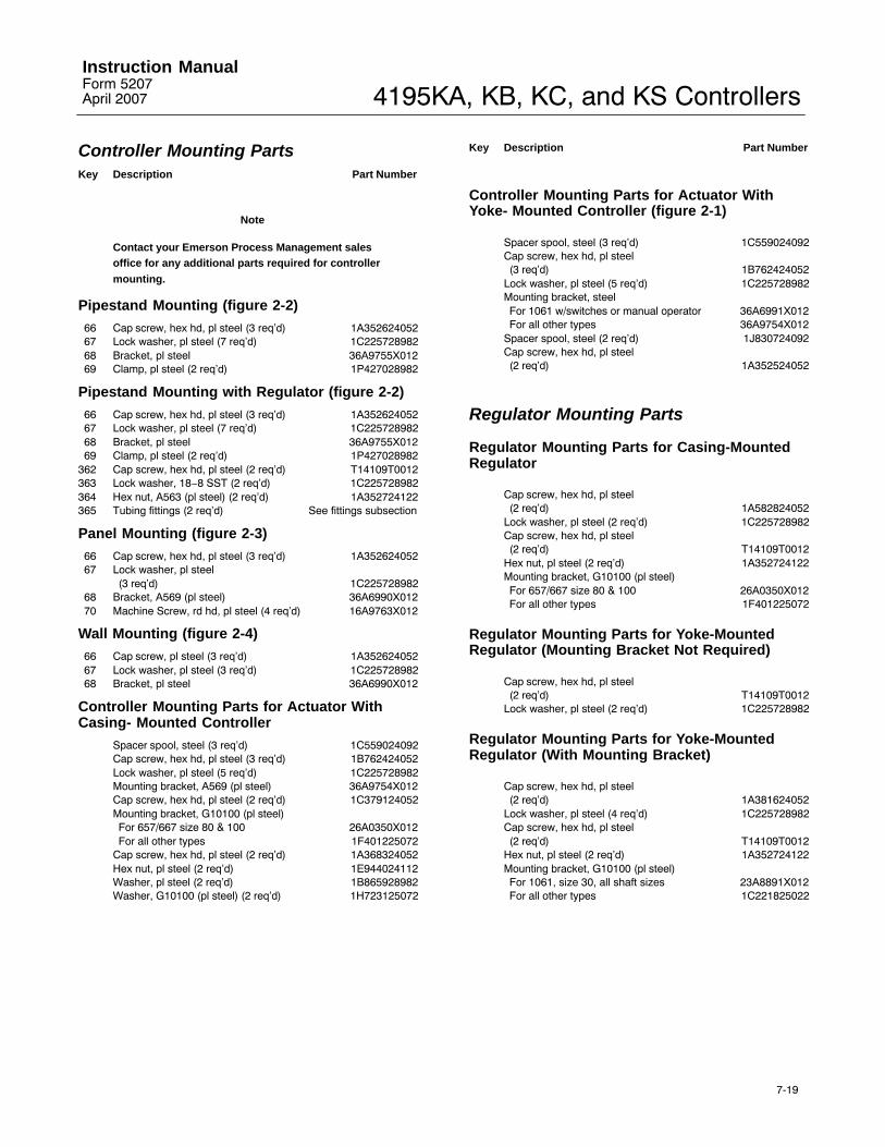
4195KA, KB, KC, and KS ControllersInstruction ManualForm 5207April 2007
7-19
Controller Mounting PartsKey Description Part Number
Note
Contact your Emerson Process Management salesoffice for any additional parts required for controllermounting.
Pipestand Mounting (figure 2-2)
66 Cap screw, hex hd, pl steel (3 req�d) 1A35262405267 Lock washer, pl steel (7 req�d) 1C22572898268 Bracket, pl steel 36A9755X01269 Clamp, pl steel (2 req�d) 1P427028982
Pipestand Mounting with Regulator (figure 2-2)
66 Cap screw, hex hd, pl steel (3 req�d) 1A35262405267 Lock washer, pl steel (7 req�d) 1C22572898268 Bracket, pl steel 36A9755X01269 Clamp, pl steel (2 req�d) 1P427028982
362 Cap screw, hex hd, pl steel (2 req�d) T14109T0012363 Lock washer, 18−8 SST (2 req�d) 1C225728982364 Hex nut, A563 (pl steel) (2 req�d) 1A352724122365 Tubing fittings (2 req�d) See fittings subsection
Panel Mounting (figure 2-3)
66 Cap screw, hex hd, pl steel (3 req�d) 1A35262405267 Lock washer, pl steel
(3 req�d) 1C22572898268 Bracket, A569 (pl steel) 36A6990X01270 Machine Screw, rd hd, pl steel (4 req�d) 16A9763X012
Wall Mounting (figure 2-4)
66 Cap screw, pl steel (3 req�d) 1A35262405267 Lock washer, pl steel (3 req�d) 1C22572898268 Bracket, pl steel 36A6990X012
Controller Mounting Parts for Actuator WithCasing- Mounted Controller
Spacer spool, steel (3 req�d) 1C559024092Cap screw, hex hd, pl steel (3 req�d) 1B762424052Lock washer, pl steel (5 req�d) 1C225728982Mounting bracket, A569 (pl steel) 36A9754X012Cap screw, hex hd, pl steel (2 req�d) 1C379124052Mounting bracket, G10100 (pl steel)For 657/667 size 80 & 100 26A0350X012For all other types 1F401225072
Cap screw, hex hd, pl steel (2 req�d) 1A368324052Hex nut, pl steel (2 req�d) 1E944024112Washer, pl steel (2 req�d) 1B865928982Washer, G10100 (pl steel) (2 req�d) 1H723125072
Key Description Part Number
Controller Mounting Parts for Actuator WithYoke- Mounted Controller (figure 2-1)
Spacer spool, steel (3 req�d) 1C559024092Cap screw, hex hd, pl steel(3 req�d) 1B762424052
Lock washer, pl steel (5 req�d) 1C225728982Mounting bracket, steelFor 1061 w/switches or manual operator 36A6991X012For all other types 36A9754X012
Spacer spool, steel (2 req�d) 1J830724092Cap screw, hex hd, pl steel(2 req�d) 1A352524052
Regulator Mounting Parts
Regulator Mounting Parts for Casing-MountedRegulator
Cap screw, hex hd, pl steel(2 req�d) 1A582824052
Lock washer, pl steel (2 req�d) 1C225728982Cap screw, hex hd, pl steel(2 req�d) T14109T0012
Hex nut, pl steel (2 req�d) 1A352724122Mounting bracket, G10100 (pl steel)For 657/667 size 80 & 100 26A0350X012For all other types 1F401225072
Regulator Mounting Parts for Yoke-MountedRegulator (Mounting Bracket Not Required)
Cap screw, hex hd, pl steel(2 req�d) T14109T0012
Lock washer, pl steel (2 req�d) 1C225728982
Regulator Mounting Parts for Yoke-MountedRegulator (With Mounting Bracket)
Cap screw, hex hd, pl steel(2 req�d) 1A381624052
Lock washer, pl steel (4 req�d) 1C225728982Cap screw, hex hd, pl steel(2 req�d) T14109T0012
Hex nut, pl steel (2 req�d) 1A352724122Mounting bracket, G10100 (pl steel)For 1061, size 30, all shaft sizes 23A8891X012For all other types 1C221825022
4195KA, KB, KC, and KS ControllersInstruction Manual
Form 5207April 2007
7-20
FittingsKey Description Part Number
Note
The quantity shown make up the fitting for one endof the tubing or hose. Specify quantity of fittingsrequired.
Fittings for 3/8-inch tubing, casing- oryoke-mounted controller with regulatorConnector, brass (2 req�d) 1B885618992Elbow, brass (2 req�d) 1B884618992
Fittings for 3/8-inch tubing,pipestand-mounted controller with regulatorElbow, brass (2 req�d) 1B884618992
Key Description Part Number
Fittings for 3/8-inch tubing,all controllers without regulatorConnector, brass (1 req�d) 1B885618992Elbow, brass (1 req�d) 1B884618992
Fittings for 1/2-inch synthetic rubber hose,all controllers w/ or w/o regulatorConnector, 316 SST 15A6002XK32Elbow, 316 SST 15A6002XK12Swivel, 316 SST (2 req�d) 15A6002XK22
Emerson Process ManagementMarshalltown, Iowa 50158 USACernay 68700 France Sao Paulo 05424 BrazilSingapore 128461
www.Fisher.com
The contents of this publication are presented for informational purposes only, and while every effort has been made to ensure their accuracy, theyare not to be construed as warranties or guarantees, express or implied, regarding the products or services described herein or their use or applicability. We reserve the right to modify or improve the designs or specifications of such products at any time without notice.
Neither Emerson, Emerson Process Management, nor any of their affiliated entities assumes responsibility for the selection, use and maintenanceof any product. Responsibility for the selection, use and maintenance of any product remains with the purchaser and end-user.
�Fisher Controls International LLC 1983, 2007; All Rights Reserved Printed in USA
Fisher is a mark owned by Fisher Controls International LLC, a member of the Emerson Process Management business division of Emerson Electric Co. Emerson Process Management, Emerson, and the Emerson logo are trademarks and service marks of Emerson Electric Co. Allother marks are the property of their respective owners.