419 instrument
TRANSCRIPT
8/10/2019 419 Instrument
http://slidepdf.com/reader/full/419-instrument 1/126
Tidal Test Tank Project Page | 1
Table of Contents
1 Introduction .................................................................................................................................... 8
1.1 The Team ................................................................................................................................. 8
1.1.1 Team Role Selection ......................................................................................................... 9
1.1.2 Company Organisational Structure................................................................................ 11
1.2 The Business Plan .................................................................................................................. 12
1.2.1 Mission ........................................................................................................................... 12
1.2.2 Aims and Objectives ....................................................................................................... 12
1.2.3 Marketing and Promotion Strategy ............................................................................... 12
1.2.4 Competitive Advantage ................................................................................................. 13
1.2.5 Future Products and Services ........................................................................................ 13
1.3 Issues and Constraints ........................................................................................................... 14
2 Project Description ....................................................................................................................... 15
2.1 Problem Analysis ................................................................................................................... 15
2.2 Team Strategy on Solution Formulation ............................................................................... 16
2.2.1 Project Management Tools ............................................................................................ 16
3 Research ....................................................................................................................................... 19
3.1 Market Research ................................................................................................................... 19
3.1.1 Market Analysis .............................................................................................................. 19
3.1.2 Size and Trends of the Market ....................................................................................... 19
3.1.3 Target Market ................................................................................................................ 20
3.1.4 Existing Customers ......................................................................................................... 20
3.2 Customer Requirements ....................................................................................................... 20
3.2.1 Stakeholders .................................................................................................................. 21
3.2.2 Stakeholder Requirements ............................................................................................ 23

8/10/2019 419 Instrument
http://slidepdf.com/reader/full/419-instrument 2/126
Tidal Test Tank Project Page | 2
3.3 Final Customer Requirements ............................................................................................... 24
3.4 Product Life Cycle .................................................................................................................. 25
3.5 Medway River Research ........................................................................................................ 28
3.5.1 Types of Ports................................................................................................................. 28
3.5.2 Typical Test tank facilities .............................................................................................. 31
4 Product Analysis ........................................................................................................................... 32
4.1 Functional Analysis ................................................................................................................ 32
4.2 Customer Attributes to Product Characteristics Conversion Analysis .................................. 33
5 The Solution .................................................................................................................................. 35
5.1 The Different Solutions ......................................................................................................... 35
5.1.1 Tide Simulation .............................................................................................................. 36
5.1.2 Water Level Control ....................................................................................................... 36
5.1.3 Salinity Control ............................................................................................................... 36
5.1.4 Temperature Control ..................................................................................................... 37
5.1.5 Test Tank Dimensions .................................................................................................... 37
5.2 Quality Function Deployment ............................................................................................... 39
5.3 Quality Assurance Management System .............................................................................. 42
5.3.1 Standards ....................................................................................................................... 42
5.3.2 Ergonomics ..................................................................................................................... 43
5.3.3 Quality Costs .................................................................................................................. 44
5.4 G6 Tidal Solutions Quality Policy ........................................................................................... 45
6 Proposed Design ........................................................................................................................... 39
6.1 System Components List ....................................................................................................... 39
6.2 Process Flow Design .............................................................................................................. 41
6.3 Control system Design ........................................................................................................... 44

8/10/2019 419 Instrument
http://slidepdf.com/reader/full/419-instrument 3/126
Tidal Test Tank Project Page | 3
6.3.1 Control System ............................................................................................................... 45
6.3.2 Advantages of using the Lab-view PC Interface............................................................. 49
6.3.3 Control System Parts List ............................................................................................... 49
6.3.4 Control System Work Breakdown Structure .................................................................. 50
6.4 Electrical Systems Products and Design ................................................................................ 51
6.4.1 System Requirements .................................................................................................... 51
6.4.2 Electrical System Design ................................................................................................ 52
6.4.3 Electrical Components List ............................................................................................. 53
7 Manufacturing Plan ...................................................................................................................... 55
7.1 Supply Chain .......................................................................................................................... 57
7.1.1 Supply Chain Process ..................................................................................................... 57
7.1.2 Organizations Identified in the Supply Chain ................................................................ 58
7.2 Triangle of Forces Analysis (Quality, Time, Costs) ................................................................ 58
8 Product Costing ............................................................................................................................ 59
8.1 Procurement Policy ............................................................................................................... 61
8.1.1 Definition ....................................................................................................................... 61
8.1.2 Purpose .......................................................................................................................... 61
8.1.3 Organisational Scope and Compliance .......................................................................... 61
8.1.4 Policy Content and Guidelines ....................................................................................... 62
8.1.5 Documentation of Procurement Decision, Payment and Taxation ............................... 62
8.1.6 Procurement Tools ......................................................................................................... 63
8.1.7 Terms and Conditions .................................................................................................... 63
8.1.8 Environmental Requirements ........................................................................................ 63
8.1.9 Legal Obligations ............................................................................................................ 64
8.1.10 Supplier Relationships .................................................................................................... 64

8/10/2019 419 Instrument
http://slidepdf.com/reader/full/419-instrument 4/126
Tidal Test Tank Project Page | 4
9 Health and Safety ......................................................................................................................... 65
9.1 Health and Safety in the Tidal Tank Area (client responsibility) ........................................... 65
9.2 Tidal Tank and Reservoir Tank .............................................................................................. 66
9.3 Electrical Health and Safety .................................................................................................. 67
9.4 Platform Health and Safety ................................................................................................... 68
9.5 Health and Safety Life Cycle .................................................................................................. 69
10 Services ..................................................................................................................................... 70
10.1 Maintenance Program........................................................................................................... 70
10.2 Tank Maintenance ................................................................................................................. 70
10.3 Reservoir Maintenance ......................................................................................................... 71
10.4 Components Maintenance .................................................................................................... 71
10.4.1 Sensors ........................................................................................................................... 71
10.4.2 Pump .............................................................................................................................. 72
10.4.3 Valves, Pipes and Fittings ............................................................................................... 72
10.5 Platform Maintenance .......................................................................................................... 72
10.6 Breakdown ............................................................................................................................ 72
10.7 Recommended Planned Maintenance Schedule .................................................................. 72
11 Environmental Impact and Consideration ................................................................................ 73
11.1 What are the overall impacts on the environment from the project? ................................. 73
11.2 Trade effluent ........................................................................................................................ 74
11.2.1 Water Pollution Regulations .......................................................................................... 74
11.2.2 Saltwater Disposal .......................................................................................................... 75
11.3 Disposing Tank Materials ...................................................................................................... 76
11.3.1 Reusing Components in the System .............................................................................. 76
11.3.2 Complete Disposal of the System .................................................................................. 77

8/10/2019 419 Instrument
http://slidepdf.com/reader/full/419-instrument 5/126
Tidal Test Tank Project Page | 5
12 Bibliography .............................................................................................................................. 78
APPENDICES ......................................................................................................................................... 81
APPENDIX 1 – PROJECT GANTT CHARTS .............................................................................................. 82
APPENDIX 2 – TIDAL TANK SPECIFICATION .......................................................................................... 86
APPENDIX 3 – TANK SUPPORT ASSEMBLY DRAWING .......................................................................... 91
APPENDIX 4 – USER PLATFORM DRAWING ......................................................................................... 96
APPENDIX 5 – SALT WATER CREATION ................................................................................................ 98
13 APPENDIX 6 – PERSONAL PROFILES ........................................................................................ 102
APPENDIX 7 – PEER REVIEW REPORTS ............................................................................................... 109
14 APPENDIX 8 – MISCELLANEOUS DRAWINGS .......................................................................... 116
Table of Figures
Figure 1: Company Logo and Contact Details ........................................................................................ 8
Figure 2: G6 Tidal Solutions Team Profile .............................................................................................. 9
Figure 3: G6 Tidal Solutions Organisational Structure ......................................................................... 11
Figure 4: Tidal Test Tank Project Stakeholders .................................................................................... 22
Figure 5: Customer and Stakeholder Relationship .............................................................................. 22
Figure 6: Stakeholder Requirements ................................................................................................... 23
Figure 7: Flow Diagram for Determination of Customer Requirements ............................................. 24
Figure 8: Product Life Cycle Diagram Invalid source specified. ........................................................... 26
Figure 9:Tidal Test Tank Product Life Cycle Diagram ........................................................................... 26
Figure 10: Example of a closed port (Medway Ports overview map, 2011) ........................................ 29
Figure 11:Example of an open port (Medway Ports overview map, 2011) ......................................... 30
Figure 12: Example of a dry dock (Daniel Adamson Preservation Society, 2011) ............................... 30
Figure 13: Tidal test Tank QFD Matrix ................................................................................................. 40
Figure 14: Solution Path ....................................................................................................................... 41
Figure 15: Quality and Profitability (Summers, 2000) ......................................................................... 44
Figure 16: Assembly of the Proposed Design ...................................................................................... 39
8/10/2019 419 Instrument
http://slidepdf.com/reader/full/419-instrument 6/126
Tidal Test Tank Project Page | 6
Figure 17: Work Breakdown Structure ................................................................................................ 40
Figure 18: The path taken by water in the system .............................................................................. 41
Figure 19: Control Technique Comparison .......................................................................................... 44
Figure 20: Control System Design Process (Dorf & Bishop, 2005) ....................................................... 45
Figure 21: Instrumentation Schematic ................................................................................................ 48
Figure 22: Control System Work Breakdown Structure....................................................................... 50
Figure 23 Electrical Wiring System Diagram ........................................................................................ 54
Figure 24: Project Implementation Gantt Chart (Time Estimation) .................................................... 55
Figure 25: Project Implementation Network Diagram ........................................................................ 56
Figure 26: Supply Chain Management and Process ............................................................................ 57
Figure 27: Triangle of Forces Analysis .................................................................................................. 58
Figure 28: Health and Safety Cycle (Phil Hughes, 2009) ...................................................................... 69
Figure 29 :"Reduce, Reuse, and Recycle" Waste management (the 2e element) .............................. 73
Figure 30 End-of-life FRP Components ................................................................................................ 76
Figure 31: Tidal Testing Facility ............................................................................................................ 87
Figure 32: Chart of concentration converted to salt requirements. ................................................. 101

8/10/2019 419 Instrument
http://slidepdf.com/reader/full/419-instrument 7/126
Tidal Test Tank Project Page | 7
List of Tables
Table 1: The team’s individual Belbin Score .......................................................................................... 9
Table 2: Team roles and individual duties ........................................................................................... 10
Table 3: Tidal Test Tank Functional Analysis ........................................................................................ 33
Table 4: Customer Attributes to Product Characteristics .................................................................... 34
Table 5: Table of flow rates for tide cycles .......................................................................................... 43
Table 6: Mechanical Parts List.............................................................................................................. 43
Table 7: Level Transducer Specification ............................................................................................... 46
Table 8: Instrument and Equipment List.............................................................................................. 49
Table 9: List of Electrical Components ................................................................................................. 53
Table 10: Task Identification ................................................................................................................ 56
Table 11: Table of Costs ....................................................................................................................... 60
Table 12:Table of salinity concentration converted to salt requirements ........................................ 100

8/10/2019 419 Instrument
http://slidepdf.com/reader/full/419-instrument 8/126
Tidal Test Tank Project Page | 8
1 Introduction
G6 Tidal Solutions Limited is a small Engineering Consultancy Design Company involved in
producing technical and design solutions. The company specialises in consulting for small to
medium sized organisations in need of innovative solutions in the Marine Industry. Effective project
management and great discipline are some of the key factors that make G6 Tidal Solutions a
reliable consultant company that is sure to deliver the best results for the best time.
Some of the services that are carried out by the organisation include the design and manufacture of
once-off specialised marine test rigs, creating solutions to problems faced with equipment in
marine environments and designing methods of best practice in order to improve longevity ofalready existing marine equipment.
Figure 1: Company Logo and Contact Details
1.1 The Team
G6 Tidal Solutions is made up of 6 team members. A tool that is now popular in team role selection
was used to determine the roles played by each team member. This tool is known as the Belbin
Team Roles Theory. It identifies the typical roles that can be characteristic to varying extents in
individuals working in a group dynamic. A Team Role came to be defined as “A tendency to behave,
contribute and interrelate with others in a particular way.” (Associates, 2007)
The members of the team are each dedicated individuals in pursuit of excellence. Each member
plays a role that is vital in order for the team to succeed as a united entity. There is also a degree of
flexibility with each role to allow for accountability and responsibility of the entire organization.
9 St. Mary’s Industrial Estate
Chatham Maritime
8/10/2019 419 Instrument
http://slidepdf.com/reader/full/419-instrument 9/126
Tidal Test Tank Project Page | 9
1.1.1 Team Role Selection
C o o r d i n a t o r
S h a p e r
R e s o u r c e
I n v e s t i g a t o r
P l a n t
T e a m
W o r k e r
M o n i t o r
E v a l u a t o
r
I m p l e m e
n t e r
C o m p l e t
e r
F i n i s h e r
Gugulethu 0 23 11 0 4 0 13 19
Chi Wai 4 9 7 21 5 8 7 9
Evans 4 6 12 8 13 10 10 8
Ofonama 10 10 4 8 6 10 13 11
Laykun 10 10 8 12 11 4 7 7
Chinelo 9 6 7 3 7 5 9 25
Leadership Individual Harmonistic DeliveryOutward Looking Inward Looking
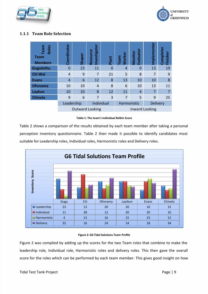
Table 1: The team’s individual Belbin Score
Table 2 shows a comparison of the results obtained by each team member after taking a personal
perception inventory questionnaire. Table 2 then made it possible to identify candidates most
suitable for Leadership roles, Individual roles, Harmonistic roles and Delivery roles.
Figure 2: G6 Tidal Solutions Team Profile
Figure 2 was complied by adding up the scores for the two Team roles that combine to make the
leadership role, Individual role, Harmonistic roles and delivery roles. This then gave the overall
score for the roles which can be performed by each team member. This gives good insight on how
Gugu Chi Ofonama Layikun Evans Chinelo
Leadership 23 13 20 20 10 15
Individual 11 28 12 20 20 10
Harmonistic 4 13 16 15 23 12
Delivery 32 16 24 14 18 34
I n v e n t o r y S c o r e
G6 Tidal Solutions Team Profile
T e
a m
R o
l e s
Team
Members

8/10/2019 419 Instrument
http://slidepdf.com/reader/full/419-instrument 10/126
Tidal Test Tank Project Page | 10
to distribute work that needs to be carried out in the duration of the group project to ensure
optimum individual contribution to the task at hand.
Names Roles Duties
Gugulethu Moyo Team Manager
Chair Meetings
Set Weekly Goals
Distribute Tasks
Review Team Progress
Mechanical Design
Ofonama Archibong Assistant Manager
Team Administration
Control &
Instrumentation Systems
Design
Chinelo S. Ifeji Business Services Consultant Set Up Business Plan
Marketing Research
Procurement and Product
costing policies
Chi Wai Wan Design Services Consultant
Technical Designs and
Drawings
Assembly Instructions
Layikun Berhanu Electrical Engineering Consultant Electrical Systems Design
Environmental
Considerations
Evans Waithira Health and Safety Consultant
Health and Safety
Platform Design
Table 2: Team roles and individual duties
The roles and duties outlined in Table 2 are an indication of the primary roles performed by each
member. Each member showed flexibility in carrying out other important duties that were outside
their primary roles. As a result, the team was able to function as a whole by providing a great
working dynamic relationship amongst members.

8/10/2019 419 Instrument
http://slidepdf.com/reader/full/419-instrument 11/126
Tidal Test Tank Project Page | 11
1.1.2 Company Organisational Structure
Figure 3: G6 Tidal Solutions Organisational Structure
One of the factors that affect the success of an organisation is the organisational structure.
It is of grave importance to have a clear organisational structure in order to ensure that the
right decisions are made in the company by the correct people. It also provides a clear view
of the different functional departments of an organisation. It also provides a hierarchy that
indicates a chain of command that is simple for all to understand.
Business
Development
Costing and
Marketing
Business
Strategy/Plan
Market Research
(Chinelo S. ifeji)
Customer Services
(G6 Tidal Solutions Limited)
Services Department
Health and Safety
(Evans Waithira)
Consultancy(G6 Tidal Solutions Limited)
Maintenance
(Chinelo S. Ifeji)
Quality Control
(Chinelo S. Ifeji)
TEAM MANAGER
(Gugulethu Moyo)
ASSISTANT MANAGER
(Ofonama Archibong)
Engineering Division/
Technical Support
Mechanical Operations
(Chi Wai , Gugulethu,
Ofonama )
Electrical Operations
(Layikun Berhanu, Evans
Waithira
Control Systems
(Layikun Berhanu, Ofonama
Archibong)
8/10/2019 419 Instrument
http://slidepdf.com/reader/full/419-instrument 12/126
Tidal Test Tank Project Page | 12
1.2
The Business Plan
In order for any company to break into a market it needs to have a solid business plan. G6
Tidal Solutions has the following business plan which will aid in the journey towards a bigger
market share.
1.2.1 Mission
The mission of the company is to become a leader in Engineering and Management
consulting by providing clients with best possible solutions and business services which can
fully satisfy their requirements.
1.2.2 Aims and Objectives
Aims: G6 Tidal Solutions aim to provide high quality goods and services to its clients
through intense customer involvement in the design of products.
Objectives:
To be selected from the client, University of Greenwich, as the leading consultingbusiness for the “Tidal-Test-Tank” project
Create and maintain strong client relationships
Become an established consultancy company in the region within the period of 3 to
5 years
To become a international organization after the first 5 years of operation
1.2.3 Marketing and Promotion Strategy
G6 will be employing various media in order to create an awareness of the services it
provides. Seeing as it is a new company, it is important to gain recognition in local areas and
in the rest of the UK as soon as possible. The first step towards becoming known is to list the
company in the Yellow Pages. The next step is to create a company brochure which will be
distributed to education institutions, professional institutions, as well as relevant exhibition
events that are to be attended by the organization. The brochure will be aimed at informing
potential clients of the organisation’s range of products and services. Furthermore the

8/10/2019 419 Instrument
http://slidepdf.com/reader/full/419-instrument 13/126
Tidal Test Tank Project Page | 13
leaflet will highlight G6 Tidal Solution Limited past experience, career highlights as well as
the expertise employed.
Digital advertising marketing will help the company to create awareness outside Greater
London area and outside the English border. The internet is able to give instant exposure to
a vast potential of clients nationally and internationally by combining interactivity,
transaction, and communication. This would allow for lead times to be reduced drastically.
Its usage will boost the business by drawing customers from all over the world. The
company’s website is thus included in any printed literature that the company G6 Tidal
Solutions distributes.
1.2.4 Competitive Advantage
The key advantages of the business are:
The firm is able to provide to customers robust products
Intense quality control and thus providing quality assurance to the client
Competitive prices
Provide optional service of commissioning and installations
Capacity to innovate and modify solutions in short lead times
Ability to work using best practice operations
Create and maintaining a great level of customer satisfaction by involving the
customer in the design of their required product
Strong initial advertising/marketing
Intense customer involvement in design to ensure customer requirements are best
met
1.2.5 Future Products and Services
The company’s focus will be on expanding and upgrading its services according to customer
needs and changes in the market in order to maintain client loyalty as well as the company’s
market share.

8/10/2019 419 Instrument
http://slidepdf.com/reader/full/419-instrument 14/126
Tidal Test Tank Project Page | 14
1.3
Issues and Constraints
The main issues and constraints faced by a company that is emerging into the business
world are that the organization is at a stage where its members are still building relations
with each other in order to have a truly functioning business. This means that although
individually experienced in respective fields, the members are still learning to work as
united entity whilst trying to build customer relations at the same time. Also, being a new
company, finances are relatively limited and this may make the organisation vulnerable to
losing clients to companies that have more money to spend on projects that are similar to
those pursues by G6 Tidal Solutions Limited.
G6 Tidal Solutions is an infant company that is not yet known by the targeted market. The
main hurdle at hand is to gain the contract with the University of Greenwich in order to
prove experience in the chosen business sector.

8/10/2019 419 Instrument
http://slidepdf.com/reader/full/419-instrument 15/126
Tidal Test Tank Project Page | 15
2 Project Description
The University of Greenwich’s School of Engineering is in need of a new Tidal -Test- Tank to
be one of the testing facilities in the Hydraulics laboratory. The aim of the group design
project is for groups to propose and tender an all encompassing design to the client, The
University of Greenwich. The School of Engineering is the main vendor and will therefore
select the most suitable design for use out of the 16 competing groups of final year
students.
2.1
Problem Analysis
G6 Tidal Solution was created so that it would be able to propose a design to the client. The
first part of the project is to be able to create a team that works and shows an
understanding of how professional engineering consultants work. That is to create an
identity and set up an organisation that has set work structures and policies that encourage
maximum individual performance.
The next part of the project is to demonstrate a systematic approach to designing and
problem solving. This requires due research to be carried out for the relevant product in
terms of Market research, Product research and all aspects of the product that need to be
considered in order to produce a product that is satisfactory for the client, and also
conforms to relevant Health and safety regulations, and Environmental regulations.

8/10/2019 419 Instrument
http://slidepdf.com/reader/full/419-instrument 16/126
Tidal Test Tank Project Page | 16
2.2
Team Strategy on Solution Formulation
The Belbin team roles identification tool was very useful in identifying the typical
characteristics of each team member. It aided the team in allocating basic team roles as
shown in Chapter 1.1.1. Once this was achieved, the team’s main strategy to ensure a
successful outcome to the project was as follows.
1. Maintaining high level of discipline to enable effective communication and time
management
2. Encouragement of intellectual input from all members in terms of the direction to be
taken by the team and direct involvement where major decisions needed to be made
3. Intensive research into the product and customer requirements
4. Identification of the different systems within the Main Tidal Test Tank System
5. Allocation of the design of various subsystems that make up the whole tidal test tank
main system to different team members.
6. Protection of confidential information
This strategy has proved to be successful in delivering a complete project within the giventimescales.
2.2.1 Project Management Tools
Each group of people working in a team is likely to have different of managing a project. G6
Tidal Solutions employed the following project management tools to ensure that the project
was carried out to the required quality and within the given time scales.
Time Management
Microsoft Project: The group used this tool to a plan of the tasks that needed to
be carried out and the time allocated for each task.
Every Wednesday from 11am till 5pm was also set aside for carrying out work
that needed to be done in Nelson Computer Labs. This enabled a good work
environment for the group as all members were able to collaborate and carry out
work without delay.

8/10/2019 419 Instrument
http://slidepdf.com/reader/full/419-instrument 17/126
Tidal Test Tank Project Page | 17
Communication
Meetings: Meetings were scheduled for every Tuesday morning from the time
when the project began in order for the team to provide regular updates on
progress made. This also enabled regular intervals to review progress for each
task and to prioritise the most important goals on a weekly basis. It also allowed
the whole team to be aware of what each member was contributing. All meeting
minutes were recorded to show agendas and actions carried out. Relevant
documentation can be found in individual logbooks.
Emails and telephone conversations were used as a means of maintaining good
communication links amongst group members. Emails were also used for
distributing any documentation generated by the tasks carried out by each team
member.
Interviews were carried out for the stakeholders and customers identified in the
report to enable the team to have an understanding of requirements so that a
suitable design could be produced.
Group Motivation
On several occasions the team went out on social luncheons as a team building
technique. This proved to be very effective for team motivation as the team
members were able to interact together in high spirits.
Team members also proved the ability to support each other where certain
members may have needed assistance.
Project Actions
Each team member was able to contribute to the team in an exceptional manner.
Although tasks were delegated by the team manager, team members showed
great initiative by volunteering to carry out tasks they felt they would be able to
deliver. All main decisions were discussed by the team and agreed on so that
work could move on to the next tasks.
The project plan was followed and reviewed and amended depending on the
progress made by the team.
8/10/2019 419 Instrument
http://slidepdf.com/reader/full/419-instrument 18/126
Tidal Test Tank Project Page | 18
Brainstorming: The group had several brainstorming sessions in order to identify
key tasks that needed to be done. Also, brainstorming was used as a means of
identifying the customer requirements and to rank them in order of importance.
Material selection software, CAD software as well as Microsoft package software
were used to produce the bulk of the documented work generated by the team.
The design process involved coming up with designs and ensuring that primary
requirements were satisfied. The design was amended several times in order for
a practical product to be proposed to the client. Some of the designs formulated
were abandoned due to cost factors, some for health and safety reasons, and
some for not being able to meet all primary requirements.
A Shared Drive was created for easy access to group information. All meeting
minutes as well as research literature were uploaded and shared on this system
so that each member of the team has easy access to group information.

8/10/2019 419 Instrument
http://slidepdf.com/reader/full/419-instrument 19/126
Tidal Test Tank Project Page | 19
3 Research
In the engineering Industry or any other industry, every project undertaken by any
organisation requires a level of professionalism that is relevant to the industry. The main
method of ensuring that high standards of professionalism are employed in company
projects is to carry out relevant research before the project is set in motion in order to avoid
epic failures that lead to catastrophe, loss of money, and loss of market share.
3.1
Market Research
Market Research is a systematic, objective collection and analysis of data about a particular
target market, competition, and environment.
The purpose of any market research project is to achieve an increased understanding of the
subject matter. With markets throughout the world becoming increasingly more
competitive, market research is now on the agenda of many organisations, whether they
are large or small. (Definition of Market Research, 2005-2011)
3.1.1 Market Analysis
To fully understand the targeted market and to efficiently meet customer requirements,
suggestions and complaints from clients have been analysed and evaluated. Additionally,
detailed research on the project, industries and companies related to the subject has been
carried out. G6 Tidal Solutions encourages its customers to give feedback on the services
they receive in order to ensure that standards of service are at their best levels at all times.
3.1.2 Size and Trends of the Market
G6 Tidal Solutions is currently in competition with 16 organizations for the Tidal Test Tank
Project contract bid. The potential Client is the University of Greenwich. The University will
select the company which will offer the following:
Best solution
High quality service

8/10/2019 419 Instrument
http://slidepdf.com/reader/full/419-instrument 20/126
Tidal Test Tank Project Page | 20
Low-cost design
From investigations so far completed, it is possible to confirm there is a market for the
offered system. Consequently, G6 Tidal Solutions will release further production of the
system as the demand grows. Therefore, the market can be defined as a Bull Market.
A Bull Market is defined as a
financial market of a group of securities in which prices are
rising or are expected to rise. The term "bull market" is most often used to refer to the stock
market, but can be applied to anything that is traded, such as bonds, currencies and
commodities. (Bull Market, 2011)
3.1.3 Target Market
The target market of the business is small to medium sized businesses and educational
institutions around the United Kingdom that are particularly interested in Marine
Engineering and Management solutions. The company will work on a basis of submitting
proposals in response to requests by potential customers. Necessary research will also be
carried out for potential customers to ensure that the organisation builds relations with
customers that share similar business interests and policies with G6 Tidal Solutions.
3.1.4 Existing Customers
The University of Greenwich is the first client of the organisation although the clientele base
is predicted to grow as the company begins to be known and recognised by other
organisations in the Marine Industry.
3.2
Customer Requirements
Customer requirements for any project or product show detail of the customer’s
expectations from the particular product, usually in their own words. The customer
requirement information is sourced through inquiry and person to person interview with
the customer in question. The customer requirements usually, but not in all cases have
primary (very important), secondary (not so important) and secondary (can be done

8/10/2019 419 Instrument
http://slidepdf.com/reader/full/419-instrument 21/126
Tidal Test Tank Project Page | 21
without) requirements that has to be met by any service provider or product designer as the
case may be.
In some cases like a project, there may be multiple customers to make use of the same final
product. In such cases, retrieving the customer requirements is more tedious as multiple
customers are involved. This is where it becomes very important to identify the
stakeholders for the project at hand.
3.2.1 Stakeholders
The stakeholders of a project are the people that are of interest in the project; these are the
people who are affected by the main decisions made with regards to a project. The
following lists the project stakeholders identified by brainstorming
Mr Rodney Beams
Mr Peter Snelling
Students
Mr Bruce Hassan
Mr Vic Cosgrove
Mr Ian Cakebread
Dr Malcolm Butler
Professor Ndy Ekere
Commercial Port Operator
Other Technical staff
Other Universities
Local Community
These listed stakeholders were classified in their order of importance and direct
involvement with the final product. See classification schematic below of the stakeholders
8/10/2019 419 Instrument
http://slidepdf.com/reader/full/419-instrument 22/126
Tidal Test Tank Project Page | 22
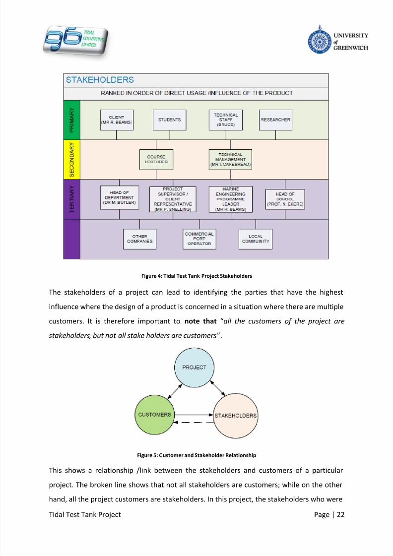
Figure 4: Tidal Test Tank Project Stakeholders
The stakeholders of a project can lead to identifying the parties that have the highest
influence where the design of a product is concerned in a situation where there are multiple
customers. It is therefore important to note that “all the customers of the project are
stakeholders, but not all stake holders are customers”.
Figure 5: Customer and Stakeholder Relationship
This shows a relationship /link between the stakeholders and customers of a particular
project. The broken line shows that not all stakeholders are customers; while on the otherhand, all the project customers are stakeholders. In this project, the stakeholders who were

8/10/2019 419 Instrument
http://slidepdf.com/reader/full/419-instrument 23/126
Tidal Test Tank Project Page | 23
not considered to be customers were mostly the tertiary stakeholders. This simple
relationship and the classified stakeholders, helped in identifying the parties whose primary
requirements were priority.
3.2.2 Stakeholder Requirements
The selected stakeholders from the above classification, who were perceived to be
customers of the project, were then interviewed to obtain individual requirements that
translated into stakeholder requirements. The selected stakeholders that were interviewed
include:
Mr Rodney Beams (Main Project Client)
Mr Peter Snelling (Client Representative)
Mr Bruce Hassan (Technician)
Mr Ian Cakebread (Technical Manager)
End User (Students)
Figure 6: Stakeholder Requirements

8/10/2019 419 Instrument
http://slidepdf.com/reader/full/419-instrument 24/126
Tidal Test Tank Project Page | 24
Customer requirements can finally be drawn from the above requirements stated by each
stakeholder/customer.
3.3
Final Customer Requirements
This was done by selecting any requirements common to all the listed stakeholders, and
then taking requirements of more important customers into consideration. Please see listed
customer requirements below, not necessarily in order of importance
Test tank should be a cheap, cost effective solution
Must be simple and easy to use / operate
The tank should be capable of performing simple tidal test
Tank should be capable of simulating the tidal behaviour of another river or marine
environment
Safe for all users to operate (very important )
Easy to set up for testing
Safe location and safe working height
Reliable, durable and requires less maintenance
Capable of being self maintained
Should be physically accessible for users
The tank should have a long life span (at least 25 years)
Should provide accurate and reliable test results to users (especially students)
The diagram below is a summary of the process of determining customer requirements.
Figure 7: Flow Diagram for Determination of Customer Requirements
These customer requirements listed above are the backbone on which the project/product
design is made and completed, as the customer has to be satisfied in the listed ways. It is
important to note that the customer requirements listed could be further classified into
groups in order of importance from primary to tertiary. It should also be noted that not all

8/10/2019 419 Instrument
http://slidepdf.com/reader/full/419-instrument 25/126
Tidal Test Tank Project Page | 25
the requirements were supplied by the customer as they may not know what they want
sometimes, but know what they do not want.
3.4
Product Life Cycle
The product life cycle (PLC) of a product is the life path of the product from conception to
disposal. When a new product is conceived and introduced into the market, it goes through
a stage concept development where no profit is made as the product is not yet released to
the market. It then goes through a stage of research and development where customer
surveys and prototype development. Again, at this stage, no sales have been made yet, thus
the product is still not yet profitable. When the product has been proved to work and
relevant market research has been carried out, the product is then introduced to the
market. At the level, customers are neither familiar nor loyal to the product.
The product’s life continues into the growth stage where it begins to gain reputation and
customer loyalty. This results in increased sales volume of the product. The maturity of the
product in the market begins when the product has a good reputation and continues to see
constant sales volume. After spending some time in maturity, the product starts to see a
decline in the sales volume as a result of age, lack of improvement and even market
saturation.
Improvements to products and new market strategies at intervals when the product
experiences some decline, can increase the life span of the product. After complete decline
of the product it can be disposed appropriately. The producer can begin to change its
facilities so that it begins to produce alternative products. This pattern of product life cycle
is general for all products and can be configured to suite special situations.
The life of a product experiences changes in the marketing situation, and maybe the sales
outcome of the product as a whole may be declined. When this happens, the manufacturers
have to device a means to increase the sales volume of the product back to an acceptable
level even if not as much as the previous sales volume before the decline.

8/10/2019 419 Instrument
http://slidepdf.com/reader/full/419-instrument 26/126
Tidal Test Tank Project Page | 26
Figure 8: Product Life Cycle Diagram Invalid source specified.
The Tidal Test Tank is a one off product, but experiences the same life cycle as any other
product would, from inception, to decline and disposal. The life cycle can be suited to the
status of the test tank as a special case. Below is a schematic of the tidal test tank PLC
Figure 9:Tidal Test Tank Product Life Cycle Diagram
The sales axis of the tidal tank is represented by the product’s functions in the above
schematic. The test tank will be contracted out to the company; hence the customer for the
product is already available. This means that the product does not have to go into the
market for sale after the design and manufacture. Interestingly, in the concept and designstage, the product sees no sale (functions) as the product is not yet realised. The
8/10/2019 419 Instrument
http://slidepdf.com/reader/full/419-instrument 27/126
Tidal Test Tank Project Page | 27
introduction stage is represented by the testing and maximising the tank’s operational
functions. This involves testing the different systems that make up the product, and then
making needed adjustment so that the product is used at its optimum operation conditions.
The introductory testing stage passes and ushers in the product multiple functions provided
by the product in its operational life. This stage sees the increased functions of the product
and it represents the growth and maturity stage of the test tank. After some time of being
used, the factors of age, wear and tear on components start to show as the components of
the system start to break down. Most common examples of this include corrosion which can
further lead to failure of the critical components such as pumps and valves. This
phenomenon therefore reduces the functionality of the test tank, and marks the onset of
the product decline.
The decline of the test tank can be delayed by carrying out major service as indicated at set
intervals, or even component change, for example changing pumps every 2 or 3 years. It is
however important to note that, the service and change carried out on the tank would not
restore it to its initial level of operational functionality, as indicated on the PLC diagram
above. The decline stage can then be allowed to fully set in when the expected operational
life (about 25 years) of the product has been fulfilled or when the product becomes
redundant.
The disposal of the product after its service is very important and marks the end of the PLC.
Disposing of the tank system involves firstly assessing the extent of disposal that has to be
done. When this is completed, the components of the tank that could still be useful for
other purposes are identified and dismantled off the main system. The rest of the system
can then be dismantled, with the recyclable parts sent off for recycling and the non
recyclable parts disposed off appropriately.

8/10/2019 419 Instrument
http://slidepdf.com/reader/full/419-instrument 28/126
Tidal Test Tank Project Page | 28
3.5
Medway River Research
The purpose of the tidal test tank is to be able to mimic the tide characteristics of the
Medway River. The first step towards being able to simulate the Medway River tides was to
find out the tide behaviour of the river. The Medway river average tidal range is known to
be 5.7m (East, 2007). A study of free tide charts indicated that the highest tides in Chatham
can reach heights of 6.65m at high spring tides. (Admiralty, 2011)
Another factor to be considered is the type of water that flows in the Medway River. In
order to design as tank that holds a close resemblance to the Medway River, it is important
to also know the condition of the water that flows in the river. It would be easy to assume
that the river Medway contains fresh water. However, because it is a tidal river, it has a back
flow of sea water. This water is saltier than fresh water, however less salty than sea water.
This is known as brackish water. The water in the river becomes more salty in the direction
of the sea. The concentration of salt in sea water is an average of about 35g of salt per litre
of sea water. Brackish water ranges from 5g to 30g of salt per litre of water. (Crest, 2010)
3.5.1 Types of Ports
It has not been stated what kind of port for which the tidal test tank will be used to test port
operations. Thus it made sense to research on the types of ports that exist. There are 3
types of ports. The first is known as a closed port. An example is Medway port. This is a port
where by basins are created that are accessed by ships through locks. The water in this type
of port is kept at a constant level. As a result, the port operations within the basins are not
affected by the rise and fall of the tide. However, the ships are scheduled to go in and out of
the port depending on the tides; if the tide is too low then the ships have to wait for it to
rise again before they can leave or enter the port.
The second type of port is known as a open port. An example of an open port is Sheerness.
The water level in the port rises and falls with the tide. This means that ships have a limited
amount of time to load and unload.

8/10/2019 419 Instrument
http://slidepdf.com/reader/full/419-instrument 29/126
Tidal Test Tank Project Page | 29
The third type of port is known as a dry port. This is a type of port that is used for ship
maintenance amongst other port operations. This type of port is known as a dry dock
because the basin where the ship s contained has the water in it fully drained when the
ships are being handled.
Figure 10: Example of a closed port (Medway Ports overview map, 2011)

8/10/2019 419 Instrument
http://slidepdf.com/reader/full/419-instrument 30/126
Tidal Test Tank Project Page | 30
Figure 11:Example of an open port (Medway Ports overview map, 2011)
Figure 12: Example of a dry dock (Daniel Adamson Preservation Society, 2011)

8/10/2019 419 Instrument
http://slidepdf.com/reader/full/419-instrument 31/126
Tidal Test Tank Project Page | 31
3.5.2 Typical Test tank facilities
The different tests that a towing tank is used for tests on ship models. Such tests include
resistance tests, cavitation tests, propulsion tests and open water test amongst other tests
that can be carried out on scaled down models of ships. The most common tanks are towing
tanks that are much bigger that is required in this project. As a result it was necessary to
deviate from the normal type of towing tank designs.

8/10/2019 419 Instrument
http://slidepdf.com/reader/full/419-instrument 32/126
Tidal Test Tank Project Page | 32
4 Product Analysis
In order for any designer to be able to design a product that is required by his client, it is
important for an analysis of the product to be carried out. Such an analysis enables the
designer to identify any constraints that need to be overcome in order for the product to
have certain attributes required by the client. A designer is thus able to identify the tools
needed for a solution to be formulated with regards to satisfying customer requirements.
4.1 Functional Analysis
A product function is defined as the normal actions that are performed by the particular
device or product (WebFinance Inc, 2011). Where the tidal test tank is concerned, the
product functions would be what the tasks the tank is expected to perform and any other
functions that may come as a by-product of having the tidal test tank. An obvious function
of the tidal test tank is “tidal testing”, which could be regarded as a primary funct ion of the
product. All other functions that the tank can satisfy that are not as important as the
primary function can be considered to be secondary and tertiary functions.
On another hand, functionality is the ability for a product to perform a particular task or
function (Farlex Inc, 2011). This implies that the functional analysis of a product not only
shows the intended and possible functions of the product, but also the expected ability of
performing the named product functions.
The above named function is however not all the possible functions of the tidal tank, hence
the tank functional analysis shows all the functions of the tidal tank, both intended and
possible and also its expected capabilities in a hierarchical order of importance. The product
function analysis was obtained through interaction with the customers and by
brainstorming within the group. The functional data in table 3 was a result of the analysis
carried out.

8/10/2019 419 Instrument
http://slidepdf.com/reader/full/419-instrument 33/126
Tidal Test Tank Project Page | 33
PRIMARY SECONDARY TERTIARY
Execute Essential Tidal Tests Crane Supports for lifting test ship
model
Perform other marine related
tests
Contain Salt Water Tank Accessibility Aesthetics
Pump Salt Water Mooring Maintenance
Hold Model Test Ship Chain Blocks Water Storage Unit
Simulate Tidal Characteristics of
River Medway
Ergonomics (Usability)
Mimic Port Operations
Control Temperature, water
level and salinity
Table 3: Tidal Test Tank Functional Analysis
In the above functional analysis also show functional requirements of the tidal test tank
product. The hierarchy of classification is as follows
Primary Functions: The functions of the product that are basic/necessary to its
operation.
Secondary Functions: These are not basic to the operation of the product, but are
however desired by the user with relatively less significant importance compared
with the primary requirements.
Tertiary Functions: These are desired functions that hold the least importance. They
can only be achieved when all the primary and secondary functional requirementshave been achieved.
4.2
Customer Attributes to Product Characteristics Conversion Analysis
The customer attributes are expectations of the customer in terms of requirements from
the product of interest. These attributes cannot be quantified or measured as they are
desires; hence the service provider has to determine a way to relate to the attributes. On
the other hand, characteristics are the physical properties of the product that can be

8/10/2019 419 Instrument
http://slidepdf.com/reader/full/419-instrument 34/126
Tidal Test Tank Project Page | 34
quantified/measured and therefore controlled. These then enable the designer to set limits
for the design so that the customer attributes are provided.
CUSTOMER ATTRIBUTES PRODUCT CHARACTERSITCS
Execute Essential Tidal Tests Use pump to move water in and out of tank
Tank solution should be Cheap Tank to exceed not more than £75000
Safe Working Height Height not more than 1m
Long Service LifeTank designed to last at least 25 years
Control Water Temperature Use heater, chiller and sensors to monitor and
control the temperature
Control Water Salinity Use salinometer to monitor the water salinity
Table 4: Customer Attributes to Product Characteristics

8/10/2019 419 Instrument
http://slidepdf.com/reader/full/419-instrument 35/126
Tidal Test Tank Project Page | 35
5 The Solution
The product developed to be designed is a tidal test tank aimed as simulating the tidal
motion of the Medway River. The tank also has the capabilities of simulating tidal
movement of other Port environments around the world. This product will be designed to
be mostly automatic and simple to operate and use. The automated parts of the system
limit the amount of manual control by the test tank operator, making the system safe.
Different system parameters are specified in this chapter, some of which are driven by
customer requirements and also government policy. The set parameters will then be used
to design a product that satisfies the customer and the stakeholders.
5.1
The Different Solutions
After having set all the parameters that were to be designed for, a number of solutions were
formulated in order to create a test tank system capable of satisfying all basic customer
requirements. Brain storming is the main tool that was used to determine the way in which
each requirement was to be satisfied. Following brainstorming, different solution design
solution ideas were generated and were then considered one after another. The most viable
idea at a time was chosen and critically examined including the feasibility and realisation of
the solution.
This method of generation the solution to the tank design problem helped the group have
multiple design ideas that could be employed with minimal modifications as the problem
solution. When the likely design was chosen by the group, unfolding developments at the
time forced the group to review and modify the design to suite the situation, solving the
problem or eliminating it completely. After this stage and all design integrity have been met,
the design was finalised as the group’s solution to the tidal test tank project. In summary,
the design solution involved the following steps in sequence
Generate Design Ideas – Consider Ideas – Choose Design – Review Design – Finalise Design

8/10/2019 419 Instrument
http://slidepdf.com/reader/full/419-instrument 36/126
Tidal Test Tank Project Page | 36
5.1.1 Tide Simulation
In order to be able to simulate the tide movements, it was determined that the tidal test
tank would need to have a reservoir that would contain the volume of water required to
produce the rise and fall of water level in the tidal test tank. This was the main concept
around which most of the detail of the design was based on.
The next consideration was the duration of the testing times. The tide in the river rises and
falls every 6 hours. It would be very time consuming to carry out tests on a real time basis.
Also, the users of the tank, the university students, would use the testing facility during a
laboratory session. The laboratory sessions at the university last for 2 hours. It would thus
make sense to simulate a tide rise/ fall in 2 hours. Water level in the test tank would change
from high to low, or low to high in a 2 hour laboratory session.
5.1.2 Water Level Control
Having reservoir means that a means of moving water between the test tank and the
reservoir is needed. The two tanks would be arranged so that the reservoir can be at high
level, and gravity could be used to move the water from the reservoir to the test tank. A
pump would thus be used to pump water back to the reservoir. This method was not
adopted as it provided no means of a controlled flow rate of water from the reservoir to the
test tank. The flow rate of water would be highest when the reservoir is full, and then
reduce as the water level in the reservoir drops. As a result, this arrangement was not used.
5.1.3
Salinity Control
It was considered to have a dosing unit for the test tank in order to make brackish water for
the tidal test tank. The dosing unit would have a concentrated solution of brine and then be
used to make the required concentrations of brackish water in the test tank. Water
becomes saturated with salt at about at concentration slightly higher than sea water levels.
With a dosing unit at this concentration, the dosing unit would need to have a mixing tank
that is about the same size at the test tank. Consequently, this was not to be pursued for the
test tank on account of the system becoming complicated and unnecessarily costly.

8/10/2019 419 Instrument
http://slidepdf.com/reader/full/419-instrument 37/126
Tidal Test Tank Project Page | 37
5.1.4 Temperature Control
A temperature range is required for the tidal testing facility. This is 0oC to 40oC. There are
many ways in which water can have heat added to it or removed from it. The most viable
solutions formulated for this were the use of electrical heating elements to heat the water,
and to use a chiller to cool the water.
5.1.5 Test Tank Dimensions
As mentioned earlier in the report, most test tank facilities that exist tend to be very large.
In this case, research revealed that only one ship model needs to be tested at a time during
any laboratory sessions. The largest model is about 2m long. The tidal test tank needs to be
able to accommodate such a model, so its’ length is to be no less than 2.5m.
1.
Defined Operational Conditions
PARAMETER VALUE REASONS
WORKING FLUID 0 – 35 g/l saltwaterThe tank would normally contain salt or fresh
water for test purposes
WATER LEVEL
(MIN – MAX)0.2 - 1 m
The tank would contain salt water up to 1m
high
OPERATING
TEMPERATURE
RANGE
0 - 40 o
CThe tank water temperature may vary
depending the conditions to be simulated
STATIC PRESSURE
(MIN – MAX)
4.03 - 10.01
kPa absolute
Pressure force as a result of stagnant water
level
2.
Physical and Mechanical Characteristics
TANK DEPTH 1.2m Physical dimensions and measurements of the
tank
SHAPE Rectangular Prism Physical tank shape
MATERIAL GFRPTank material should be capable of handling
the force, exerted by weight of water
STANDS Anti-vibration Feet Aide in vibration management
ACCESSIBILITY PlatformPlatform around the tank with a barrier
structure to stop users from leaning into tank
8/10/2019 419 Instrument
http://slidepdf.com/reader/full/419-instrument 38/126
Tidal Test Tank Project Page | 38
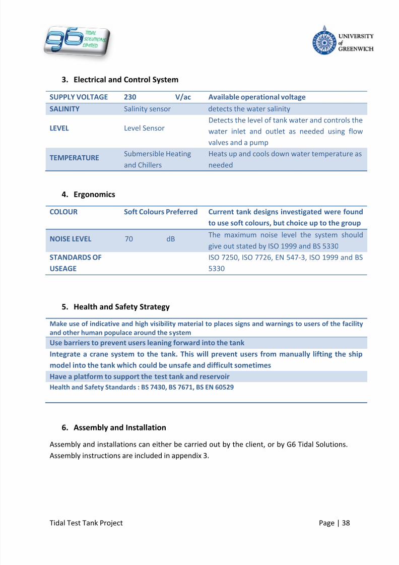
3.
Electrical and Control System
SUPPLY VOLTAGE 230 V/ac Available operational voltageSALINITY Salinity sensor detects the water salinity
LEVEL Level SensorDetects the level of tank water and controls the
water inlet and outlet as needed using flow
valves and a pump
TEMPERATURESubmersible Heating
and Chillers
Heats up and cools down water temperature as
needed
4.
Ergonomics
COLOUR Soft Colours Preferred Current tank designs investigated were found
to use soft colours, but choice up to the group
NOISE LEVEL 70 dBThe maximum noise level the system should
give out stated by ISO 1999 and BS 5330
STANDARDS OF
USEAGE
ISO 7250, ISO 7726, EN 547-3, ISO 1999 and BS
5330
5.
Health and Safety Strategy
Make use of indicative and high visibility material to places signs and warnings to users of the facility
and other human populace around the system
Use barriers to prevent users leaning forward into the tank
Integrate a crane system to the tank. This will prevent users from manually lifting the ship
model into the tank which could be unsafe and difficult sometimes
Have a platform to support the test tank and reservoir
Health and Safety Standards : BS 7430, BS 7671, BS EN 60529
6.
Assembly and Installation
Assembly and installations can either be carried out by the client, or by G6 Tidal Solutions.
Assembly instructions are included in appendix 3.
8/10/2019 419 Instrument
http://slidepdf.com/reader/full/419-instrument 39/126
Tidal Test Tank Project Page | 39
5.2
Quality Function Deployment
The quality function deployment (QFD) is a visual decision making tool which shows how
existing and proposed solutions for a certain application are matched with customer
requirements (WebFinance Inc, 2011). It transforms the customer requirements into design
quality which can be used to deploy functions to meet that stated design quality. The QFD
matrix is also known as the House of Quality (HOQ Matrix) and is comprised of various
rooms interacting with each other to make up the entire house.
The rooms are Customer Requirements: this is where customer requirements are represented in
their own words.
Planning Matrix: this room shows how existing products including this company’s
product fairs with the named customer requirements.
Technical Requirements: this room is also known as the engineering characteristics.
The information here is developed by the design team who identify the measurable
characteristics of the product that are related to meeting the customer
requirements.
Interrelationships: this is the main body if the HOQ matrix and it identifies the
relationship between the customer requirements and the technical requirements.
Roof: this identifies the areas where the technical requirements that characterise the
product support or impedes one another.
Targets: this is the last room in the HOQ matrix and it summarises the data
contained in the other rooms and final design targets.

8/10/2019 419 Instrument
http://slidepdf.com/reader/full/419-instrument 40/126
Tidal Test Tank Project Page | 40
Figure 13: Tidal test Tank QFD Matrix
Having identified QFD as a viable quality tool, the group decided to carry out a QFD analysis.
The illustration in figure 14 is the result of the QFD analysis carried out by the group to
check the quality and integrity of the design. Have such a QFD analysis, the group can
determine the acceptance of the product by providing customers with what they require,
hence avoiding failure.
As a summary, the group took careful solution steps in a systematic sequential order to
achieve the optimum solution to the problem at hand. See the schematic below for a
summary of the solution tools used by the group to achieve the final solution

8/10/2019 419 Instrument
http://slidepdf.com/reader/full/419-instrument 41/126
Tidal Test Tank Project Page | 41
Figure 14: Solution Path

8/10/2019 419 Instrument
http://slidepdf.com/reader/full/419-instrument 42/126
Tidal Test Tank Project Page | 42
5.3
Quality Assurance Management System
In order to develop a quality product, the company has established an effective quality
management system. The foundation of a quality organisation is the concept of the
customer and supplier working together for their mutual benefits; consequently the
customer-supplier interfaces are extended into and outside the organisation.
Quality Management System will help to direct and control the business in order to
continually improve the effectiveness and efficiency of its performance.
Thanks to this system two basic requirements will be met:
Customer’s requirements: confidence in the ability of the organisation to deliver the
desired design and service consistently meeting their needs and expectations
Organisation’s requirements: efficient use of the available resources at an optimum
cost
Quality Management Systems are used in all sectors of the business and it will:
Set direction and meet customer’s expectations
Improve process control
Reduce time and wastage
Lower costs
Increase market share (QUALITY MANAGEMENT SYSTEM (QMS) STANDARD, 2011)
5.3.1 Standards
The following standards will be used to monitor the quality of the product and service:
ISO 9000: 2000 – Quality Management Systems – Fundamentals and Vocabulary
ISO 9001: 2000 – Quality Management Systems – Requirements
ISO 9004: 2000 – Guidelines for Performance Improvement
ISO 1400 – Environment Management Standard (Summers, 2000)

8/10/2019 419 Instrument
http://slidepdf.com/reader/full/419-instrument 43/126
Tidal Test Tank Project Page | 43
These standards are built around business processes, with a strong emphasis on
improvement and a focus on meeting the needs of the customers. In fact, the family of ISO
9000 contains eight quality management principles, upon which to base an efficient,
effective, and adaptable QMS, which are applicable throughout industry, commerce and
service sectors:
Customer Focus
Leadership
Involving People
Process Approach
Systems Approach
Continual Improvement
Factual Decision Making
Mutually Beneficial Supplier Relationships (Quality Management Systems, 2011)
5.3.2 Ergonomics
The Company in order to develop a quality design has followed these standards:
ISO 7250: 1996 Basic Human Body Measurement for technological design
ISO/TR 16071: 2003 Ergonomics of Human System Interaction- Guidance on
Accessibility for human-computer interfaces
ISO/TR 16982: 2002 Ergonomics of Human System Interaction- Usability methods
supporting Human-Centred Design
ISO 7726: 1998 Ergonomics of the thermal environment- Instruments for measuring
physical quantities
ISO/CD 20282-1 Ease of operations of everyday products- part 1: context of use and
user characteristics
ISO/CD 20282-2 Ease of operations of everyday products- part 2: Test method
EN 547-3: 1996 Safety of machinery- Human body measurements- part 3
Anthropometric data (Pheasant, 1998)
ISO 1999 – Methods for estimating the risk of hearing damage (NOISE)
8/10/2019 419 Instrument
http://slidepdf.com/reader/full/419-instrument 44/126
Tidal Test Tank Project Page | 44
The design has been constructed for members of user population who fall between the 5 th
and 95th
percentiles in any particular respect; hence 90% of users are accommodated within
the design limits. (Pheasant, 1998)
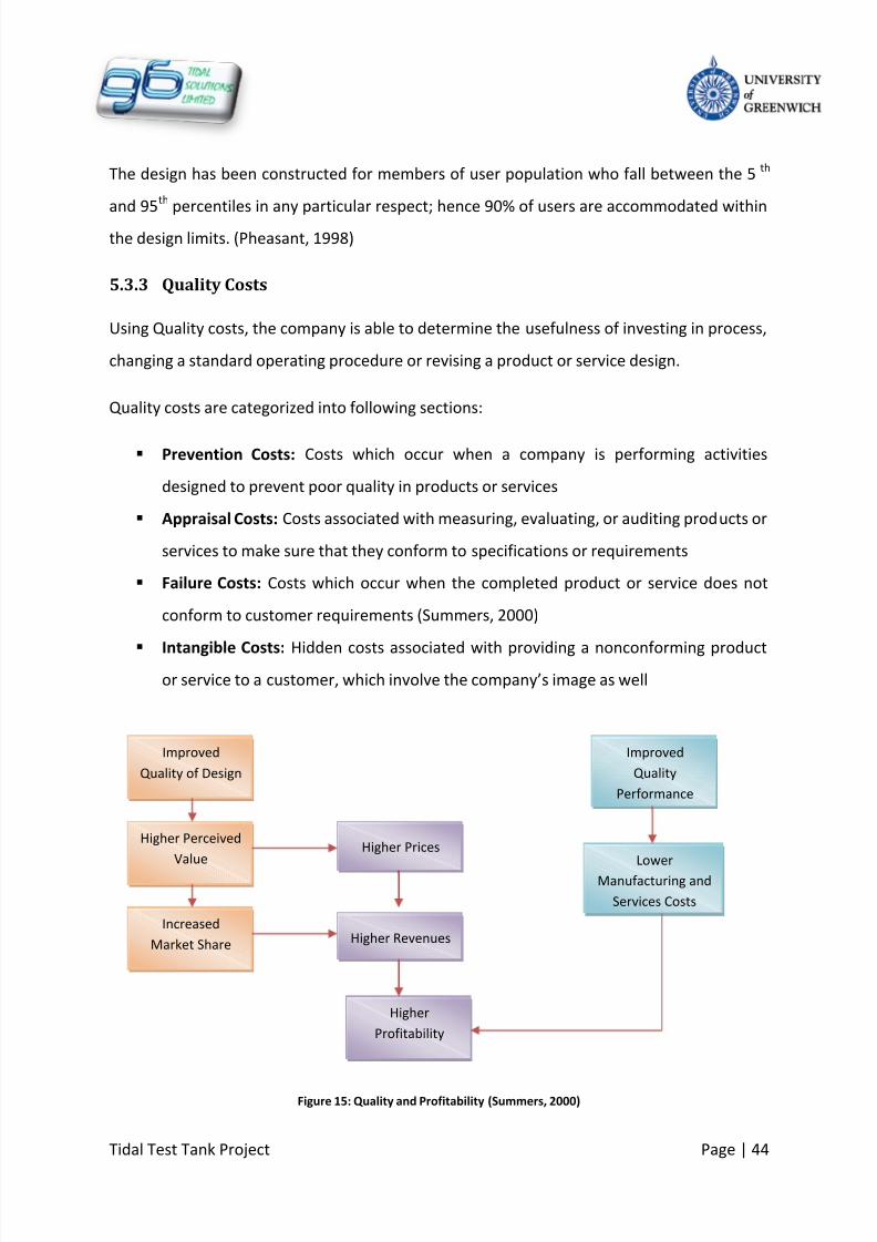
5.3.3 Quality Costs
Using Quality costs, the company is able to determine the usefulness of investing in process,
changing a standard operating procedure or revising a product or service design.
Quality costs are categorized into following sections:
Prevention Costs: Costs which occur when a company is performing activities
designed to prevent poor quality in products or services
Appraisal Costs: Costs associated with measuring, evaluating, or auditing products or
services to make sure that they conform to specifications or requirements
Failure Costs: Costs which occur when the completed product or service does not
conform to customer requirements (Summers, 2000)
Intangible Costs: Hidden costs associated with providing a nonconforming productor service to a customer, which involve the company’s image as well
Figure 15: Quality and Profitability (Summers, 2000)
Improved
Quality of Design
Higher Perceived
Value
Increased
Market Share
Higher Prices
Higher
Profitability
Higher Revenues
Improved
Quality
Performance
Lower
Manufacturing and
Services Costs

8/10/2019 419 Instrument
http://slidepdf.com/reader/full/419-instrument 45/126
Tidal Test Tank Project Page | 45
5.4
G6 Tidal Solutions Quality Policy
The overall policy of the company is to provide organisation, people and resources to supply
our customers with products and services which satisfy their requirements in every respect.
Additionally, it is G6 Tidal Solutions Limited policy to continually improve the quality by
monitoring, measuring and enhancing the company’s Quality and Procedural System.
The organisation’s approach to Quality Assurance has been designed to satisfy the goals
stated in the Business Plan. It intends to ensure that appropriate conditions are in place in
order to follow international and local standards and legislations, and to fulfil customer
needs.
To achieve G6 Tidal Solutions objectives, the company will provide ongoing development of
management processes by:
Using and developing key performance indicators
Being innovative
Investing in new technology
Continually developing the expertise, professionalism and integrity of the entire
company
Following environmental legislations
Signing contracts with suppliers ISO 9001 certified

8/10/2019 419 Instrument
http://slidepdf.com/reader/full/419-instrument 46/126
Tidal Test Tank Project Page | 39
6
Proposed Design
After much consideration and having carried out necessary analyses, the following design is
being proposed to be manufactured as the tidal test tank.
Figure 16: Assembly of the Proposed Design
Refer to Appendix A for the complete Product Specification and technical drawings
6.1
System Components List
Tidal Test Tank
Reservoir
Pump
Salinometer
PC
Pipes and fittings
Chiller
Electric heating elements
Level sensor
Valves
Tank Support platform
User Platform

8/10/2019 419 Instrument
http://slidepdf.com/reader/full/419-instrument 47/126
Tidal Test Tank Project Page | 40
Figure 17: Work Breakdown Structure

8/10/2019 419 Instrument
http://slidepdf.com/reader/full/419-instrument 48/126
Tidal Test Tank Project Page | 41
6.2
Process Flow Design
Figure 18: The path taken by water in the system

8/10/2019 419 Instrument
http://slidepdf.com/reader/full/419-instrument 49/126
Tidal Test Tank Project Page | 42
The Process flow design illustrates the path taken by the water when it is moved for the
tidal simulations.
On initial set up, the main test tank will be filled to the High Water Level from the mains in
order to provide the full volume of water required in the system which is about 3000 litres.
Water from the test tank will be fed to the reservoir by means of gravity through an
actuated control valve. The control valve will limit the flow rate to required amounts. The
reservoir is only large enough to hold the required movable water to create tide simulations
in the tide testing facility. The volume of movable water needed for tidal rise and fall in the
test tank is 1800 litres. This amounts to a low and high level of 0.2 m and 1 m respectively.
When the reservoir contains water at the High Water Level (HWL) mark (0.45m), the test
tank is at Low Water Level (LWL) (0.2m), which is the lowest water level allowed in the test
tank. When water in the test tank is at the HWL mark, then the reservoir is at its LWL mark.
From the reservoir, water is moved by a single phase pump at full speed through a flow
reducing throttle valve. At this point, any excess water from the pump is sent back to the
reservoir, and the required flow rate is sent directly to the test tank. Alternatively, water can
be fed to the test tank via the chiller when the water needs to be chilled.
When water reaches the LWL in the reservoir, a switch is triggered in the reservoir that
stops the pump, preventing overflow in the test tank and potential damage to the pump.
This means that the test tank is full and the test tank is at HWL. At this level, the actuated
valve at the test tank outlet can then be opened so that it begins to feed water back to the
reservoir. Then when water reaches LWL in the test tank, the actuated valve is commanded
to shut fully.
When the water reaches the HWL in the reservoir, a switch is triggered that will start the
pump so that it feeds water to the test tank. This means that the system can run tide cycles
automatically whilst the user carries out measurements. The automatic cycles range from 2
hours to 6 hours depending on the set flow rates for the experiments. The flow rates can be
set on the Labview PC.

8/10/2019 419 Instrument
http://slidepdf.com/reader/full/419-instrument 50/126
Tidal Test Tank Project Page | 43
Water for 1 cycle [m3
] 1800Simulated Tide Range [m] 1
Pipe Internal Diameter[cm] 3
Time [hours] 2 3 4 5 6
Flow rate [l/m] 15 10 7.5 6 5
Velocity [m/s] 0.35 0.24 0.18 0.14 0.12
Table 5: Table of flow rates for tide cycles
Table 5 indicates the flow rates that can be achieved by the system.
Name Descript ion Suppl ier Material
Test Tank
(LxWxH)
3m x1m x 1.2m Nicholson Glass Fibre
Reinforced
Plastic
Reservoir
(LxWxH)
4.2m x 1.2x 0.5m Nicholson Glass Fibre
Reinforced
Plastic
Pipes 3cm Ø
1.5cm Ø
Piscis PVC
Tank Connectors Tank to pipe
connectors
Piscis PVC
Pipe Connectors Pipe threaded
joints
Piscis PVC
Tank Support
Structure
Stand for the
tank
Parker Steel & Sons Steel
User Platform - RS Components Wood
Guard Rails - RS Components Steel
Stairs - Ladderstore Wood
Table 6: Mechanical Parts List

8/10/2019 419 Instrument
http://slidepdf.com/reader/full/419-instrument 51/126
Tidal Test Tank Project Page | 44
6.3
Control system Design
The test tank is designed to simulate tidal characteristics in real and scaled time as
required. Also to be controlled by the test tank are the water salinity, water temperature
and water flow rate. These requirements necessitated the design of a control system to
monitor and control the named parameters. In the process of designing this control system,
different control techniques came up and were briefly investigated to choose the best
option. They are
Mechanical Control: This involves the use of mechanical instruments to monitor andcontrol the said parameters. For example, using a hydrometer to measure the
salinity of the water.
Instrumentation: This involves the use of electronic instruments that have been pre-
programmed to measure and possibly control certain quantities.
Electronic Programmable Circuits: Sensing instruments are employed and controlled
using self programmed electronic circuits.
Figure 19: Control Technique Comparison

8/10/2019 419 Instrument
http://slidepdf.com/reader/full/419-instrument 52/126
Tidal Test Tank Project Page | 45
6.3.1 Control System
The schematic above was used as a comparison tool between the three control techniques.
Instrumentation was chosen to be used in the control system design. This meant that
sensors and similar instruments to measure control the stated quantities had to be selected
in the process of designing the control system
Figure 20: Control System Design Process (Dorf & Bishop, 2005)
The above design process was followed to select the necessary instrumentation in the
process of designing the control system. The goal of the control system, was to achieve a
fully or semi automatic control of certain quantities. The important quantities to monitor
and control were
Water Temperature
Water Salinity
Water Level
Water Flow Rate

8/10/2019 419 Instrument
http://slidepdf.com/reader/full/419-instrument 53/126
Tidal Test Tank Project Page | 46
The listed quantities can be monitored and controlled using electronic instruments and
sensors. The sensors can only be selected by carefully determining the requirements it has
to meet in terms of performance, dimensions, protection against adverse conditions etc.
These considerations were used to write up a specification for the level control sensor.
PARAMETER VALUE UNIT REASONS
LIQUID SENSED SALT AND/OR FRESH
WATER
The test tank would normally contain salt or fresh
water which is the working fluid of the system
LEVEL RANGE TO
DETECT
0 – 1.2 m The transducer must measure water levels up to 1.2
m above the minimum (i.e. zero level). The
maximum water level in the tank is 1 m, hencehaving more level measurement capacity will check
for overflow
ACCURACY CLASS ±0.5 %FS Sometimes referred to as tolerance. The output
must be within a small percentage of the full scale
value
OPERATING
TEMPERATURE
RANGE
0 - 40oC The transducer should be capable of working in
fairly diverse temperatures. The test tank can be
used to simulate any particular marine region/area
at any weather
SPECIFIC GRAVITY
AT MAXTEMPERATURE
1.02 Dimensionless ratio of the density of the fluid
compared to a standard density. This value varieswith temperature and could affect suspended
particles
RATED OUTPUT ±5 VDC The output of the transducer should be a
reasonable DC voltage signal to allow for accurate
measurement
RESOLUTION 0.05 m The transducer must be capable of measuring small
level changes of at least 0.05 m, to have more
sampled level data and accuracy
SUPPLY VOLTAGE 5 – 15 VDC Transducers usually require excitation voltage to
operate
MAXIMUM MASS 0.75 Kg Low mass is a desired if the sensor will be placed in
the tank. There would be no distortion of results
OUTPUT
INTERFACE
USB USB serial connection to computer software should
be available. The software will assist in level
monitoring, control and data recording
CONTROL PROGRAMMABLE The sensor should be capable of being programmed
further to aide with overall system control and data
manipulation
PROTECTION CLASS IP58 Minimum The transducer must be protected against salt and
other particles. It should also be protected from
continuous immersion in water
Table 7: Level Transducer Specification
8/10/2019 419 Instrument
http://slidepdf.com/reader/full/419-instrument 54/126
Tidal Test Tank Project Page | 47
The specification was used to search for suitable level transducers for the control system.
Two transducers were identified and reviewed
1. Flowline Inc’s Echopod which uses ultrasonic means of sensing, to switch and
control the level as desired
2. Honeywell Limited’s LLE Series optical sensor, which uses infrared technology to
sense and transmit result to the controller
The two transducers were reviewed and the Honeywell optical level sensor was chosen for
the control system. Some of its features include
Small size, thereby needing less space
Digital output
Microprocessor compatible, hence programmable
Pre-wired
The above specification writing and selection method was implemented for the other
sensors and instruments and equipment used in the control system. A list of the selected
instruments and equipments can be found later in this report. The instrumentation
schematic in figure 19 shows the interaction between the sensors in the system
The chiller is shown independent on the schematic as it will not be automatically controlled
from the PC interface like the other sensors and equipment. The sensors in the control
system are to be strategically placed inside or outside the test tank as required by their
function. The measured parameters are sent back to the PC interface via hardware USBinterface. The Labview PC software interface will be used on the control panel to monitor
and control and output and inputs of the sensors in the system.

8/10/2019 419 Instrument
http://slidepdf.com/reader/full/419-instrument 55/126
Tidal Test Tank Project Page | 48
Figure 21: Instrumentation Schematic
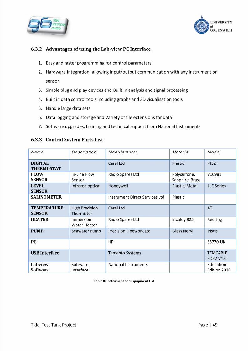
8/10/2019 419 Instrument
http://slidepdf.com/reader/full/419-instrument 56/126
Tidal Test Tank Project Page | 49
6.3.2 Advantages of using the Lab-view PC Interface
1.
Easy and faster programming for control parameters
2. Hardware integration, allowing input/output communication with any instrument or
sensor
3. Simple plug and play devices and Built in analysis and signal processing
4. Built in data control tools including graphs and 3D visualisation tools
5. Handle large data sets
6. Data logging and storage and Variety of file extensions for data
7. Software upgrades, training and technical support from National Instruments
6.3.3 Control System Parts List
Name Descript ion Manufacturer Material Model
DIGITAL
THERMOSTAT
Carel Ltd Plastic PJ32
FLOW
SENSOR
In-Line Flow
Sensor
Radio Spares Ltd Polysulfone,
Sapphire, Brass
V10981
LEVELSENSOR
Infrared optical Honeywell Plastic, Metal LLE Series
SALINOMETER Instrument Direct Services Ltd Plastic
TEMPERATURE
SENSOR
High Precision
Thermistor
Carel Ltd AT
HEATER Immersion
Water Heater
Radio Spares Ltd Incoloy 825 Redring
PUMP Seawater Pump Precision Pipework Ltd Glass Noryl Piscis
PC HP S5770-UK
USB Interface Temento Systems TEMCABLE
PDP2 V1.0
Labview
Software
Software
Interface
National Instruments Education
Edition 2010
Table 8: Instrument and Equipment List

8/10/2019 419 Instrument
http://slidepdf.com/reader/full/419-instrument 57/126
Tidal Test Tank Project Page | 50
6.3.4 Control System Work Breakdown Structure
Below is the WBS for the control system. It shows the manner in which the various control
sub-systems interact in a hierarchical order. This can also be used to represent the control
system’s bill of materials (BOM) as it will have the same content in this case only.
Figure 22: Control System Work Breakdown Structure

8/10/2019 419 Instrument
http://slidepdf.com/reader/full/419-instrument 58/126
Tidal Test Tank Project Page | 51
6.4
Electrical Systems Products and Design
An electrical system plays a significant role in the tidal test tank system. Several electrical
components have been selected based on the main supply voltage. A single phase 240V/ac
is set out as a main supply. On the basis of this restriction the components have been
selected to meet the requirements.
6.4.1 System Requirements
Control Panel: The control Panel is mainly used for the purpose of controlling the
system as a whole. Therefore the control panel will need to have several
characteristic and parameters.
Characteristics
Starts, Stops and Protects the
single phase centrifugal pump.
Functioning Over wide Voltage
Hand/Remote Resetting Over
Load Relay
Reputed make Switch Gear
Products with CE markings.
Heavy duty Start & Run
Capacitors
Indicating Lamp for Power
Supply
Load Current & Phase Voltage
Measurement
Wall Mounted Type
Ease wiring of Terminal Block
Gasketted Cover
Dust & Vermin Proof
Cable Glands for Easy Wiring
Technical Parameters
Single Phase
Voltage : 240 Volts AC
Frequency : 50 Hz
Protection : Single Phasing,
Over Load and Short Circuit
Relay Type : Thermal SPST

8/10/2019 419 Instrument
http://slidepdf.com/reader/full/419-instrument 59/126
Tidal Test Tank Project Page | 52
Transformers: A transformer is used to step down the voltage to the required output
voltage for several components within the system, due to their operating voltage
characteristics.
Voltage Regulator AC to DC: Several components are operating at a lower voltage
than specified, therefore AC to DC conversion will be required in order for the
components to operate accordingly
Wiring Cables: Different types of electrical wiring cables are used depending on the
components operating parameters. The length and diameter each cable will changebased on the operating voltage and current of each component.
Relay Switch: The relay switch is used as a circuit break from the main control panel.
5 relay circuit breakers will be required to protect the component from overload or
short circuit.
6.4.2 Electrical System Design
A design has been carried out based on the system requirements. As shown in Figure 12 the
control panel consists of 5 relay circuit breaker to protect all the components used.
Primarily one relay will be used to operate the water level sensor, temperature sensor, and
flow sensor because their operating voltage falls between 4.5 -12V/DC. Hence a transformer
is utilised to step down the voltage from 240V AC – 50V AC. Additionally, because the
sensors are operating on DC characteristics, a voltage regulator is required for the
conversion of AC to DC. The pumping system will use one relay circuit breaker given that it is
operating at 230V AC at 3.3A. Furthermore, the pumping system will have its own
Emergency Stop Push Button (ESPB) in case of a malfunction in the pumping system.
Other components such as water heater, Digital thermostat, and water chiller will have their
individual relay circuit breakers. These components will not require transformer or voltage
regulator since they are operating above 230V AC.

8/10/2019 419 Instrument
http://slidepdf.com/reader/full/419-instrument 60/126
Tidal Test Tank Project Page | 53
Moreover the value readings from the water heater, Digital Thermostat, water level sensor,
temperature sensor, and flow sensor are ought to be interfaced to a PC using a standard
USB cable.
6.4.3 Electrical Components List
Product
Description
Supplier Material Model
Control panel CLE PVC 1DS1
Relay switch RS PVC sx460
Transformer RS - CT-1000
Voltage regulator Digit-key - PTH08T220W
Wiring Cables Alert Electrical Cooper RG-59
Emergency Stop
station
Newlec Industrial
Control
Stainless steel s2750
Table 9: List of Electrical Components

8/10/2019 419 Instrument
http://slidepdf.com/reader/full/419-instrument 61/126
Tidal Test Tank Project Page | 54
Figure 23 Electrical Wiring System Diagram
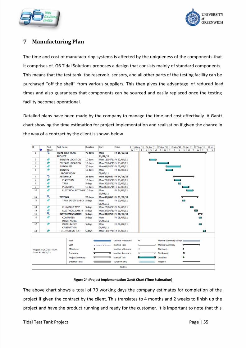
8/10/2019 419 Instrument
http://slidepdf.com/reader/full/419-instrument 62/126
Tidal Test Tank Project Page | 55
7 Manufacturing Plan
The time and cost of manufacturing systems is affected by the uniqueness of the components that
it comprises of. G6 Tidal Solutions proposes a design that consists mainly of standard components.
This means that the test tank, the reservoir, sensors, and all other parts of the testing facility can be
purchased “off the shelf” from various suppliers. This then gives the advantage of reduced lead
times and also guarantees that components can be sourced and easily replaced once the testing
facility becomes operational.
Detailed plans have been made by the company to manage the time and cost effectively. A Gantt
chart showing the time estimation for project implementation and realisation if given the chance in
the way of a contract by the client is shown below
Figure 24: Project Implementation Gantt Chart (Time Estimation)
The above chart shows a total of 70 working days the company estimates for completion of the
project if given the contract by the client. This translates to 4 months and 2 weeks to finish up the
project and have the product running and ready for the customer. It is important to note that this
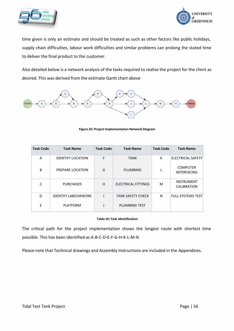
8/10/2019 419 Instrument
http://slidepdf.com/reader/full/419-instrument 63/126
Tidal Test Tank Project Page | 56
time given is only an estimate and should be treated as such as other factors like public holidays,
supply chain difficulties, labour work difficulties and similar problems can prolong the stated time
to deliver the final product to the customer.
Also detailed below is a network analysis of the tasks required to realise the project for the client as
desired. This was derived from the estimate Gantt chart above
Figure 25: Project Implementation Network Diagram
Task Code Task Name Task Code Task Name Task Code Task Name
A IDENTIFY LOCATION F TANK K ELECTRICAL SAFETY
B PREPARE LOCATION G PLUMBING LCOMPUTER
INTERFACING
C PURCHASES H ELECTRICAL FITTINGS MINSTRUMENT
CALIBRATION
D IDENTIFY LABOURWORK I TANK SAFETY CHECK N FULL SYSTEMS TEST
E PLATFORM J PLUMBING TEST
Table 10: Task Identification
The critical path for the project implementation shows the longest route with shortest time
possible. This has been identified as A-B-C-D-E-F-G-H-K-L-M-N
Please note that Technical drawings and Assembly Instructions are included in the Appendices.

8/10/2019 419 Instrument
http://slidepdf.com/reader/full/419-instrument 64/126
Tidal Test Tank Project Page | 57
7.1
Supply Chain
Seeing as most of the product is made of purchase components, A supply chain analysis has been
carried out in order to identify the links within the supply chain. This is also important as it enables
G6 Tidal Solutions to formulate a supply chain strategy that will allow for the project to be a
success.
7.1.1 Supply Chain Process
Figure 26: Supply Chain Management and Process
RAW MATERIALS SUPPLIERS MANUFACTURING
DISTRIBUTION/
DELIVERY
G6 TIDAL
SOLUTIONS
THROUGH COMPANY
CUSTOMERS
DIRECT TO CLIENT

8/10/2019 419 Instrument
http://slidepdf.com/reader/full/419-instrument 65/126
Tidal Test Tank Project Page | 58
7.1.2 Organizations Identified in the Supply Chain
RS Components U.K.
Charthouse Technology Ltd
Piscis
Instruments Direct (Services) Ltd
Pc World
Nicholson Plastics
Parker Steel&Sons
CLE
Digit-Key
Alert Electrical
National Instruments
7.2
Triangle of Forces Analysis (Quality, Time, Costs)
The triangle of forces, also known as the scope triangle shows the possible forces or tradeoffs that
are encountered in a project. These forces are
Quality: the performance and worth that can be achieved in the project
Time: the available time to complete the project
Cost: the resources available for the realisation project
The figure below shows the interaction between the above name forces
Figure 27: Triangle of Forces Analysis (WebFinance Inc, 2011)
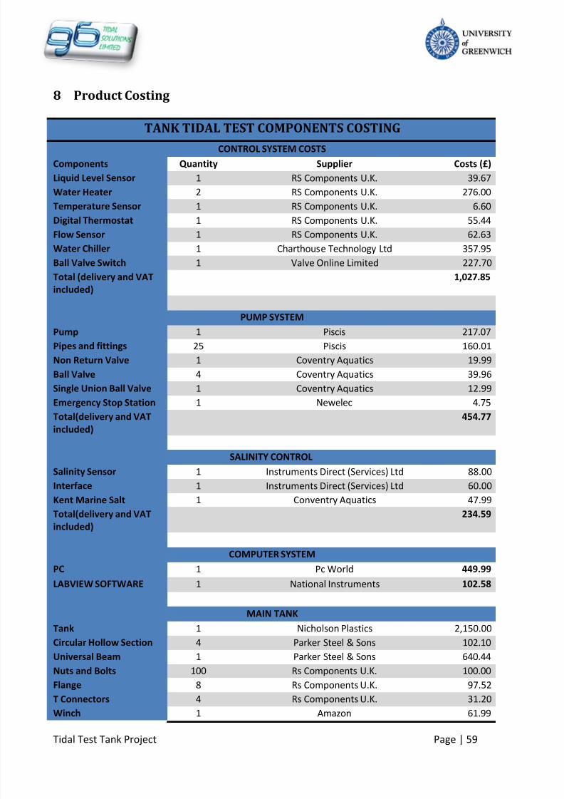
8/10/2019 419 Instrument
http://slidepdf.com/reader/full/419-instrument 66/126
Tidal Test Tank Project Page | 59
8 Product Costing
TANK TIDAL TEST COMPONENTS COSTING
CONTROL SYSTEM COSTS
Components Quantity Supplier Costs (£)
Liquid Level Sensor 1 RS Components U.K. 39.67
Water Heater 2 RS Components U.K. 276.00
Temperature Sensor 1 RS Components U.K. 6.60
Digital Thermostat 1 RS Components U.K. 55.44
Flow Sensor 1 RS Components U.K. 62.63
Water Chiller 1 Charthouse Technology Ltd 357.95
Ball Valve Switch 1 Valve Online Limited 227.70
Total (delivery and VATincluded)
1,027.85
PUMP SYSTEM
Pump 1 Piscis 217.07
Pipes and fittings 25 Piscis 160.01
Non Return Valve 1 Coventry Aquatics 19.99
Ball Valve 4 Coventry Aquatics 39.96
Single Union Ball Valve 1 Coventry Aquatics 12.99
Emergency Stop Station 1 Newelec 4.75
Total(delivery and VATincluded)
454.77
SALINITY CONTROL
Salinity Sensor 1 Instruments Direct (Services) Ltd 88.00
Interface 1 Instruments Direct (Services) Ltd 60.00
Kent Marine Salt 1 Conventry Aquatics 47.99
Total(delivery and VAT
included)
234.59
COMPUTER SYSTEM
PC 1 Pc World 449.99
LABVIEW SOFTWARE 1 National Instruments 102.58
MAIN TANK
Tank 1 Nicholson Plastics 2,150.00
Circular Hollow Section 4 Parker Steel & Sons 102.10
Universal Beam 1 Parker Steel & Sons 640.44
Nuts and Bolts 100 Rs Components U.K. 100.00
Flange 8 Rs Components U.K. 97.52
T Connectors 4 Rs Components U.K. 31.20Winch 1 Amazon 61.99

8/10/2019 419 Instrument
http://slidepdf.com/reader/full/419-instrument 67/126
Tidal Test Tank Project Page | 60
Total (delivery and VAT
included)
3,183.25
RESEVOIR Tank 1 Nicholson Plastics 1,530.00
PLATFORM
Stand 10 RS Components U.K. 189.40
Nuts and Bolts 40 RS Components U.K. 60.00
Base 2 Aluminium Wearhouse U.K. 401.82
Flanges 20 RS Components U.K. 243.80
Rails 3 RS Components U.K. 503.94
Connectors 6 RS Components U.K. 61.62
Stairs 1 Ladderstore 300.80Total (delivery and VAT
included)
1,761.38
ELECTRICAL EQUIPMENT
Control Panel 1 CLE 275.00
Relay Switch 5 RS Components U.K. 96.65
Transformer 1 RS Components U.K. 75.19
Voltage Regulator 1 Digit-Key 16.97
Wiring Cables 1 Alert Electrical 39.60
Total (delivery and VAT
included)
503.41
OVERALL PRODUCT
TOTAL
9,247.82
PRICE CHARGE 11,097.38
CONSULTANCY
Consultants 6 G6 Tidal Solutions
Man Hours 150 G6 Tidal Solutions
Rate £/hour 55 G6 Tidal Solutions
Total Charge 49,500.00GRAND TOTAL
60,597.38
Table 11: Table of Costs
The stated costs will be subject to change as the project goes through to completion. Finally, the
company has decided to adhere to high quality standards to keep out clients satisfied has in the
way also created a prolonged time to realise the project at a high cost as well. According to the
company’s method, the long time the project follows cannot be shortened, or costs reduced

8/10/2019 419 Instrument
http://slidepdf.com/reader/full/419-instrument 68/126
Tidal Test Tank Project Page | 61
without a direct negative impact on the impact on the quality of the project outcome. This
compromise can only be made by the customer if they require services to be done at a shorter time
and possibly cost.
8.1 Procurement Policy
8.1.1 Definition
A procurement policy is defined as the rules and regulations which are set in place to govern the
process of acquiring goods and services needed by an organisation to function efficiently.
The process seeks to minimize expenses associated with the purchase of goods and services by
using strategies such as volume purchasing, the establishment of vendors and supply chain and
establishing protocols which help to keep inventories low. (What Is Procurement Policy?, 2011)
8.1.2 Purpose
The purpose of this Policy is to ensure that all Procurement Activities are carried out by G6 Tidal
Solutions, by using best practice in the application of ethical standards and conduction of them in a
fair, objective and transparent manner.
These benefits will be delivered and achieved through leadership, knowledge, expertise and
facilitation of the procurement process.
8.1.3 Organisational Scope and Compliance
Only Employees with delegated procurement authority are allowed to commit expenditure to third
party; the employees engaged in these activities are required to familiarise themselves with the
content of this Policy and comply with it.
8/10/2019 419 Instrument
http://slidepdf.com/reader/full/419-instrument 69/126
Tidal Test Tank Project Page | 62
8.1.4 Policy Content and Guidelines
G6 Tidal Solutions’ Procurement Activities are guided by the principles listed below:
Apply a consistent and standard approach
Build and maintain supplier relationships
Conduct procurement activities in a manner which satisfies the requirements of
accountability and fulfil legal and financial obligations (Transport for London: Procurement
Policy, 2005)
Carry out the activities by applying professional standards required
Full compliance with this Policy is required; a breach of it may constitute misconduct Employees involved in procurement are required to observe high ethical standards; they
must promote procurement transactions in a manner which ensures the consulting
business maintains its reputation of fair, honesty and integrity dealing with suppliers
Employees involved in these activities are required to respect the confidentiality of
information they are exposed to in the course of their work, and must disclose this
information to third parties. Additionally, this information should not be used for personal
gain
G6 Tidal Solutions Limited must establish an appropriate products list to the vendor
The company has to establish the criteria to be met by any product proposed for inclusion
on a qualified products list and make this criteria available to the public and to the
interested vendors
8.1.5 Documentation of Procurement Decision, Payment and Taxation
The Team Leader of G6 Tidal Solutions Limited is in charge for the administration of
procurement functions. Delegation of authority is limited within the organisation: the
company will maintain a documented scheme of delegation for Procurement and only those
employees with delegated procurement authority will be permitted to make a third party
commitment on behalf of G6 Tidal Solutions
Comprehensive documentation should be formulated for buying decisions and processes
followed should be completed by the employees executing the transaction, and stored for a
minimum of 10 years
8/10/2019 419 Instrument
http://slidepdf.com/reader/full/419-instrument 70/126
Tidal Test Tank Project Page | 63
Common Consolidated Corporate Tax Base (CCCTB) will be used by the company for the
calculation of taxable profits (Common Tax Base , 2011)
All items should be supported by the original receipt or invoice
Whether an item invoice or receipt is not available from the supplier, the employee
executing the procurement transaction must record the details, which it will be used as
supporting documentation and submitted to the Finance Department
8.1.6 Procurement Tools
G6 Tidal Solutions Limited will use a combination of Procurement tools:
Implementing an electronic procurement system
Approved contracted suppliers who invoice the company directly
8.1.7 Terms and Conditions
The company’s terms and conditions for the supply of goods and services will form the basis of any
contract entered into with suppliers unless otherwise agreed in writing.
Terms and conditions must be established in advance of any commitment being made with a
supplier. Any exceptions must be authorised by the Team leader.
8.1.8 Environmental Requirements
Environmental procurement leads to the implementation of environmental considerations into
routine procurement decisions by buying energy-efficient products where cost and function are
equivalent over the useful life of the good.
8/10/2019 419 Instrument
http://slidepdf.com/reader/full/419-instrument 71/126
Tidal Test Tank Project Page | 64
8.1.9 Legal Obligations
G6 Tidal Solutions Limited is required to manage its policy documentation within a legislative
framework:
Financial Delegated Authority Policy
Travel and Expenses Policy
Environmentally Sustainable Procurement Guidelines
The Greater London Authority Act 1999
8.1.10 Supplier Relationships
All Suppliers will be dealt equally, with integrity, fairness and courtesy and in a professional
manner.
Relationships with suppliers should be constructive, but built on a competitive approach
which will lead to cost savings and better quality.
Collaborative and strategic alliances with key suppliers
Developing new suppliers and improving the capability of existing suppliers where
appropriate

8/10/2019 419 Instrument
http://slidepdf.com/reader/full/419-instrument 72/126
Tidal Test Tank Project Page | 65
9 Health and Safety
It is the primary responsibility of G6 Tidal Solutions to keep the high standards for health and safety
issues by identifying hazards, assessing risks, and implementing controls for the product to be
provided our clients. Guidelines of the health and safety standards within the UK regulations have
been followed.
The Health and safety standards conformed to are as follows;
British Standards; BS 7430, BS 7671, BS EN 60529
British and international standards: BS EN 61557-1:1997, IEC 6155-1:1997 (Duncan, Cahill,
& Heighway, 2006)
9.1 Health and Safety in the Tidal Tank Area (client responsibility)
1. Provision of a well-written statement or poster of the health and safety policy with clearly
identified responsibilities.
2. The reasons for any control measures to be adopted and how to use them properly.
3. Providing information, instruction, training to staff and information on all equipment
4. Ensuring that equipment is in good condition and only used for suitable operations
5. Ensuring that plant and machinery is safe to use, and that safe working practices are set up
and followed
6. All materials should be handled, stored and used safely
7.
Prohibition of eating , drinking, smoking within the tank area
8. Prevention or control of exposure to substances that may damage user health
9. Precautions against the risks caused by flammable or explosive hazards, electrical
equipment and noise.
10. Avoid potentially dangerous work involving manual handling and if it can't be avoided,
take precautions to reduce the risk of injury
8/10/2019 419 Instrument
http://slidepdf.com/reader/full/419-instrument 73/126
Tidal Test Tank Project Page | 66
11. Relevant protective clothing or equipment for examples cap, Hi-Vest, boots and gloves to
be worn where applicable
12.
Workplace and equipment should be kept clean
13. Ensure that workrooms are big enough to allow easy movement with at least 11 cubic
meters per person
14. Working areas, for examples, floors, walkways, stairs, roadways etc, should be safe to use
15. people should be protected from falling from height or into dangerous substances
9.2 Tidal Tank and Reservoir Tank
1. Water should be recycled regularly if possible
2. Tank should be kept clean
3. Potential hazards from using chemical and other substances
4. Need to ensure that right warning signs or boards are provided regarding water safety
5.
Tidal tank and reservoir should not be loaded with more than the recommended levels ofwater
6. Pressure on tank - Atmospheric pressure must be maintained in tank at all times
7. Both tanks should be inspected for leaks and signs of fatigue
8. Inspection should be carried out fittings and exterior gaskets for leaks and signs of general
corrosion and deterioration.

8/10/2019 419 Instrument
http://slidepdf.com/reader/full/419-instrument 74/126
Tidal Test Tank Project Page | 67
9.3
Electrical Health and Safety
Working with electrical equipment is made safe by carrying out suitable checks, such as inspection
or testing on all electrical equipment and components to ensure that they are in suitable working
condition. The level of inspection or testing should depend upon the risks. It is hazardous for to
work within areas with unprotected live wires.
The most common hazards that occur with electrical equipment or installation are as follows:
1. Poor maintenance of electrical equipment
2. Exposure to mains electricity supplies where UK currently supplies 240volts
3. Incorrect use of electrical equipment in potentially explosive areas
4. Poor electrical installations and faulty electric appliances are often the root cause fire
accident.
5. Avoiding of any contact with live parts causing shock and burns
6. Fixed electrical installations should be inspected and tested by a competent person at least
every three years.
7.
A test certificate confirming the date and results of the inspection and test should beprepared and displayed at all time.
8. Precautions against the risks caused by flammable or explosive hazards, electrical
equipment.
9. Electrical shock hazards: All persons should not touch electrical controls in a tank area, such
as a pump power, electrical switch; when standing on a wet floor as this can be fatal.
The client is recommended to take necessary measures to avoid such hazards and
any life threatening hazards related to working with electricity that may not be
mentioned in this document.

8/10/2019 419 Instrument
http://slidepdf.com/reader/full/419-instrument 75/126
Tidal Test Tank Project Page | 68
9.4
Platform Health and Safety
The work platform is provided with guard rails and toe boards
The platform is not to hold more than 8 persons working on the testing facility
Guard rails are provided to avoid falls due to working at height
Steps are there for access and regress to the platform
It’s suitable to be carried test before being used and inspected at least once a month to
prevent any crack forming, defects or any loosen bolts.
Any person working with the platform area should always wear relevant personal protective
equipment such safety boots, visible vest, cap, gloves were applicable.
Students working around the platform should aware of the safety issues that arise with
working at height
Workrooms must be big enough to allow easy access of movement within the platform
area.

8/10/2019 419 Instrument
http://slidepdf.com/reader/full/419-instrument 76/126
Tidal Test Tank Project Page | 69
9.5
Health and Safety Life Cycle
The diagram below shows how health and safety hazards can be identified through a cycle. A
systematic approach is essential and is based on the four steps of identifying hazards, assessing
risks, applying controls and reviewing their effectiveness.
Figure 28: Health and Safety Cycle (Phil Hughes, 2009)
8/10/2019 419 Instrument
http://slidepdf.com/reader/full/419-instrument 77/126
Tidal Test Tank Project Page | 70
10 Services
A good consultancy company provides solutions for its clients either by designing new products or
by designing modifications to the client’s already existing equipment. An excellent consultancy
company continues relations with customers after implementing solutions by recommending
methods of best practice as well as good maintenance plans. G6 Tidal Solutions offers this service
to all its clients.
10.1
Maintenance Program
G6 Tidal Solutions an organization that is committed to provide an excellent maintenance service by
providing prompt responses to problems faced by customers. As shown in the Product Life cycle, all
equipment starts to deteriorate with time and use. It is therefore necessary to be able to
recommend maintenance programmes that would enable the product’s lifespan to be lengthened.
That way, the client is able to use the equipment as long as possible.
10.2
Tank Maintenance
The main tank is made of 40% glass fibre ABS material. This material has good resistance to
chemical attack; however it is not immune to degradation caused by:
Visible light
Ozone and other extraneous pollutants
Intrinsic manufacturing impurities
Oxygen
Heat
Consequently deterioration-fighting chemicals are added to the material during the manufacturing
of the product. Moreover to extend the life span of the product, dirt and grime can be cleaned with
distilled or deionised water and strains can be removed with a non-ionic detergent. It is advisable to
avoid using solvents, as the material is likely to have a strong reaction to the solvent leading to
cracking to the product. (Restoring plastic based items, 2011)
It is also important to check for leaks periodically. The tank is made up of separate panels. Although
a sealant is used within the joints, leaks may be experienced in areas where the sealant is not

8/10/2019 419 Instrument
http://slidepdf.com/reader/full/419-instrument 78/126
Tidal Test Tank Project Page | 71
evenly distributed, or simply where the sealant has failed. Another area to regularly check for
leakages is in joints where the tank is joined to pipes and instruments (Brown, 2011). The test tank
will be containing salt, so it would be advisable to rinse out the tank with fresh water when it is fullydrained to avoid a build up of salt crystals on the walls of the tank.
10.3
Reservoir Maintenance
The reservoir is made of the same material as the tidal test tank. It would then have the same
maintenance routine as the tidal test tank. The reservoir would require occasional freshwater
rinsing to remove salt crystals. A routine check for leaks can be coincided with that of the Tidal test
tank. Focus should be made on the joints and connection for pipes and instruments.
Cracks and other signs of fatigue can be checked for every 3 years. It is important to do this as the
tank experiences cyclic loading by the pressure exerted on its walls due to the rise and fall of water
level.
10.4
Components Maintenance
Every system is as robust as its weakest component. It is therefore important to recognise that
practicing the best methods of operation includes carrying out the relevant and necessary routine
and long term maintenance procedures for the various parts that make the entire system.
10.4.1 Sensors
These can be considered to be consumables. This means that they can be replaced when they cease
to perform their required function.

8/10/2019 419 Instrument
http://slidepdf.com/reader/full/419-instrument 79/126
Tidal Test Tank Project Page | 72
10.4.2 Pump
The pump is one of the key components of the system, thus it is of great importance to keep it well
maintained. It is recommended to flush it with fresh water when it completes its service with saline
water. This will prevent the collection of salt crystals in the pump, and lengthen its lifespan. The
pump is a component that will not have the same lifespan as the tank. Consequently, every time a
main overhaul is carried out, the pump may have to be replaced, depending on its condition at the
time when the planned maintenance occurs.
10.4.3 Valves, Pipes and Fittings
The valves and pipes can be subject to clogging due to scale built up. It is recommended to de-scale
them at set intervals of the year in order to maintain high system performance.
10.5
Platform Maintenance
The platform will be used by people. It is therefore recommended that the platform be inspected
on a monthly basis to ensure that it is intact for health and safety reasons. Inspected platforms
should be tagged accordingly to ensure that they do not fail when they are in service.
10.6
Breakdown
The Tidal Testing facility has been designed in a way that avoids complete system breakdown. Each
part of the system can be independently dismantled. This enables maintenance to be carried out on
specific areas of the testing facility without disassembling the entire system.
10.7 Recommended Planned Maintenance Schedule
During the operational phase, Tidal Test Tank is recommended to be overhauled every 3 years for
inspection and repairs of any components demonstrating reduced performance.
Machinery maintenance takes place periodically when the tidal test tank is in operation. Important
environmental aspect to take under consideration is:
Discharges
Waste Management and treatment
Noise and dust emission

8/10/2019 419 Instrument
http://slidepdf.com/reader/full/419-instrument 80/126
Tidal Test Tank Project Page | 73
11 Environmental Impact and Consideration
Designing waste disposal facilities that meet the environmental rules and regulations is a complex
task because of the large number of factors that influence waste. As a result, customers are
becoming mindful of the way in which their operations affect the environment. An Environmental
Impact Assessment is required for any project that is likely alter the environment significantly.
Planning authorities require the developer to produce an environmental statement including.
A description of the development and data on the main impact it is likely to have on
the environment
A description of the likely significant environmental impacts including direct and
indirect impacts
Impact on human beings
Impact on landscape and cultural heritage
Reduce
Reuse
Recycle
Responsible
Disposal
Figure 29 :"Reduce, Reuse, and Recycle" Waste management (the 2e element)
11.1 What are the overall impacts on the environment from the project?
The project may have some significant impacts on the environment due to the use of excessive salt
water which needs to be disposed at least once every six month. In addition at the end of the
materials product’s life cycle and how it is disposed may play a significant role on the environment.
8/10/2019 419 Instrument
http://slidepdf.com/reader/full/419-instrument 81/126
Tidal Test Tank Project Page | 74
11.2
Trade effluent
Trade effluent is any liquid waste that is discharged from premises being used for a business, trade
or industries. This project in particular has considered two methods of disposing systems due to
the involvement of relatively large amount of salt water effluent involved. On the one hand, salt
water can be disposed of via waste disposing companies. A contract can be made with companies
to collect and dispose salt water on regular intervals of the year. A potential company that would
be suitable for this purpose is Envirogreen. On the other hand, salt water can be disposed of using
the mains sewerage system. However this option requires certain regulations to be obeyed by the
company or the user responsible for discharging trade effluent to a foul sewer. These are explored
later in the report. Some of the factors of concern where large volumes of salt water are being
disposed of in the sewerage are:
Damaging the sewers
Damaging the sewer treatment works
Cause a health hazard for sewerage workers or the general public
Harm the environment
11.2.1 Water Pollution Regulations
It is important to be aware of the effect of water pollution when disposing salt water. It can be
considered as a substance which capable of entering surface waters or groundwater. The following
legislations have been used as a guide to the way in which G6 Tidal Solutions recommends for salt
water disposal.
The Anti-pollution Works Regulations 1999 water resources, England and Wales No. 1006
The control of pollution ( Applications, Appeals and registers) regulations 1996
The Hazardous Waste Regulations 2005 (which implement the provisions of the European
Hazardous Waste Directive 91/689/EEC) provides a consistent definition of Hazardous
Waste and ensures environmentally sound management and regulation of such waste.

8/10/2019 419 Instrument
http://slidepdf.com/reader/full/419-instrument 82/126
Tidal Test Tank Project Page | 75
11.2.2 Saltwater Disposal
Several investigations have been made to find a solution for the problems outlined above. Hence it
is important that the company or the user complies with the restrictions regardless of how much
trade effluent is been discharged. Hence there needs to be a trade effluent agreement with the
local water and Sewerage Company before discharging any trade effluent to the sewer.
Disposing salt water via waste disposing companies will depend upon the user’s location, how the
chemical is contained as well as the type of chemical that needs to be disposed. In this case, the
effluent is 3000l of brackish water, with a potential maximum concentration that reaches seawater
levels. From the research carried out it has been concluded that to collect and dispose of hazardous
wastes, there is a minimum collection charge of £320.00 including VAT (Envirogreen).
Having listed out the environmental problems and solutions previously, it is important to outline
the responsibilities of the general user of the product as follows
Notification and registration to relevant authorities
Selection and approval of specialist contractors for the disposal of Hazardous Waste
Provision of advice to Schools and Departments regarding classification of Waste Schools
and Departments are responsible for
Ensuring they have systems for risk assessment, identification, and suitable packaging
available for the management of Hazardous Waste
Monitoring that staff, students and contractors are following the necessary systems Staff,
students and contractors are responsible for
Staff contractors who generate hazardous waste are responsible for ensuring that it is
packaged properly

8/10/2019 419 Instrument
http://slidepdf.com/reader/full/419-instrument 83/126
Tidal Test Tank Project Page | 76
11.3
Disposing Tank Materials
According to the product life cycle the tank and any other component parts related to the tank will
be dismantled and disposed of, or reused for other purposes.
11.3.1 Reusing Components in the System
Once the product has fulfilled its purpose, some of the components may need to be reused for
suitable applications. The following components could possibly be reused depending on their
operating conditions and the state they are in when the product has reach the end of its estimated
lifespan.
Pump
Sensors
Pipes PVC material
GFRP reservoir
There are some advantages in that some components, such as the sensors, have no direct contact
with the salt water hence the likelihood of damaging them is low compared to the pump. The pumpis exposed to the salt water during laboratorial operations. Also the effects of salt water on PVC and
stainless steel materials are insignificant.
Figure 30 End-of-life FRP Components
As mentioned above some components may need to be reused on the bases of their functionality.
However when recycling or disposing large amounts of materials some legislation may need to be

8/10/2019 419 Instrument
http://slidepdf.com/reader/full/419-instrument 84/126
Tidal Test Tank Project Page | 77
considered. As the waste Framework Directive requires that the waste to be classified by the type
and the purpose of its use, Generic Fibre Reinforced Polymer (GFRP) waste can be classified under
several codes of the EU waste list as follows
Frame work Directives (75/442/EEC) in 1975
Additional related document including 91/156/EEC
European waste list (commission Decision) 2000/532/EEC
11.3.2 Complete Disposal of the System
Alternatively, if there is no usable application for the components in the system, complete disposal
is the only remaining option. There are different regulations and requirements for the disposal of
materials such as GFRP, pipes, fittings and valves, and for the disposal of electrical components
such as pumps and sensors and the PC.
The estimated cost for incineration of GFRP is £120 to £150 per tonne (National Composites
Network). Other components in the system

8/10/2019 419 Instrument
http://slidepdf.com/reader/full/419-instrument 85/126
Tidal Test Tank Project Page | 78
12 Bibliography
Admiralty. (2011). Admiralty Easy Tide. Retrieved 03 22, 2011, from Admiralty Easy Tide:
http://easytide.ukho.gov.uk/EASYTIDE/EasyTide/ShowPrediction.aspx?PortID=0109&PredictionLen
gth=7
Articles: eProcurement : Electronic Procurement. (2010). Retrieved from Advanced Supply
Management: http://www.epiqtech.com/Electronic-Procurement.htm
Associates, B. (2007). Belbin Team Role Theory.
Baker, G. (2011). Lecture 1-2. Kent.
Brown, D. (2011). Guide to Fiberglass Tanks Installation and Maintenance. Retrieved 03 30, 2011,
from How-to Guides for Work: http://www.work.com/fiberglass-tanks-installation-and-maintenance-30189/
Bull Market . (2011). Retrieved March 23, 2011, from Investopedia:
http://www.investopedia.com/terms/b/bullmarket.asp
Common Tax Base . (2011, March 17). Retrieved from European Commission Taxation and Customs
Union:
http://ec.europa.eu/taxation_customs/taxation/company_tax/common_tax_base/index_en.htm
Crest, N. (2010). Estuaries in NSW . Retrieved 03 15, 2011, from Estuarine Water Quality :http://www.dnr.nsw.gov.au/estuaries/factsheets/wquality/salinity.shtml
Daniel Adamson Preservation Society . (2011). Retrieved from Daniel Adamson Preservation Society:
http://www.danieladamson.co.uk/press/dapsres/dry-dock%20web%2012.JPG]
Definition of Market Research. (2005-2011). Retrieved March 23, 2011, from Market Research, By
DJS Research Ltd:
http://www.marketresearchworld.net/index.php?option=com_content&task=view&id=14&Itemid=
38
Dorf, R. C., & Bishop, R. H. (2005). Modern Control System, Tenth Edition. New Jersey: Pearson
Prentice Hall.
Duncan, M., Cahill, F., & Heighway, P. (2006). Health and Safety at Work Essentials. London:
Lawpack Publishing Limited.
East, M. C. (2007, July). River Medway Report. Retrieved from www.marinesoutheast.co.uk
Ergonomics resources . (2002). Retrieved from Humanics Ergonomics: http://www.humanics-
es.com/recc-ergonomics.htm

8/10/2019 419 Instrument
http://slidepdf.com/reader/full/419-instrument 86/126
Tidal Test Tank Project Page | 79
Farlex Inc. (2011). Functionality . Retrieved March 15, 2011, from TheFreeDictionary :
http://www.thefreedictionary.com/functionality
Medway Ports overview map. (2011). Retrieved from Medway Ports:http://www.medwayports.com/maps/index.htm
Pheasant, S. (1998). Body Space: Anthropometry, Ergonomics and the Design of Work. United
Kingdom: Taylor&Francis, Inc.
Phil Hughes, E. F. (2009). Introduction to Health & Safety at work. Oxford: Elsevier limited .
Procurement Regulations. (2010). Retrieved from Metropolitan Sewer District:
http://www.msdlouky.org/insidemsd/pdfs/finalprocure.pdf
QUALITY MANAGEMENT SYSTEM (QMS) STANDARD. (2011). Retrieved from
http://www.wrightquality.co.uk/iso_9001_quality_management_systems.html
Quality Management Systems. (2011). Retrieved from From Quality to Excellence:
http://www.businessballs.com/dtiresources/quality_management_systems_QMS.pdf
Quality Policy . (2000). Retrieved from Long&Marshall Limited:
http://www.longmar.com/missionstatement.html
Restoring plastic based items. (2011). Retrieved March 29, 2011, from Telecommunications
Heritage Group (UK): http://www.thg.org.uk/special_interest/Tips_plastic.html
Schlickman, J. J. (2003). ISO 9001:2000 Quality Management System Design . Norwood: Artech
House, Inc.
Summers, D. C. (2000). Quality. New Jersey: Prentice Hall, Inc.
Supply Chain Management . (2011). Retrieved from Connect Group Integrated Subcontractors:
http://www.connectsystems.eu/index.php?id=303
Transport for London: Procurement Policy. (2005). Retrieved from Transport for London:http://www.tfl.gov.uk/assets/downloads/businessandpartners/procurement-policy-april-05.pdf
Vorley, G. (1993 ). Quality Assurance Management (Principles and Practice). England: Nexus
Business Communication Limited.
WebFinance Inc. (2011). Function. Retrieved March 15, 2011, from BusinessDictionary.com:
http://www.businessdictionary.com/definition/function.html
WebFinance Inc. (2011). Quality Function Deployment (QFD) Matrix . Retrieved March 16, 2011,
from BusinessDictionary.com: http://www.businessdictionary.com/definition/quality-function-deployment-QFD-matrix.html

8/10/2019 419 Instrument
http://slidepdf.com/reader/full/419-instrument 87/126
Tidal Test Tank Project Page | 80
What Is Procurement Policy? (2011, February 21). Retrieved from Wise Geek:
http://www.wisegeek.com/what-is-procurement-policy.htm

8/10/2019 419 Instrument
http://slidepdf.com/reader/full/419-instrument 88/126
Tidal Test Tank Project Page | 81
APPENDICES
8/10/2019 419 Instrument
http://slidepdf.com/reader/full/419-instrument 89/126
Tidal Test Tank Project Page | 82
APPENDIX 1 – PROJECT
GANTT CHARTS
1. PROJECT GANTT CHART
2. UPDATED PROJECT GANTT CHART
3. COMPANY PROJECT IMPLEMENTATION GANTT CHART

8/10/2019 419 Instrument
http://slidepdf.com/reader/full/419-instrument 90/126
Tidal Test Tank Project Page | 83

8/10/2019 419 Instrument
http://slidepdf.com/reader/full/419-instrument 91/126
Tidal Test Tank Project Page | 84
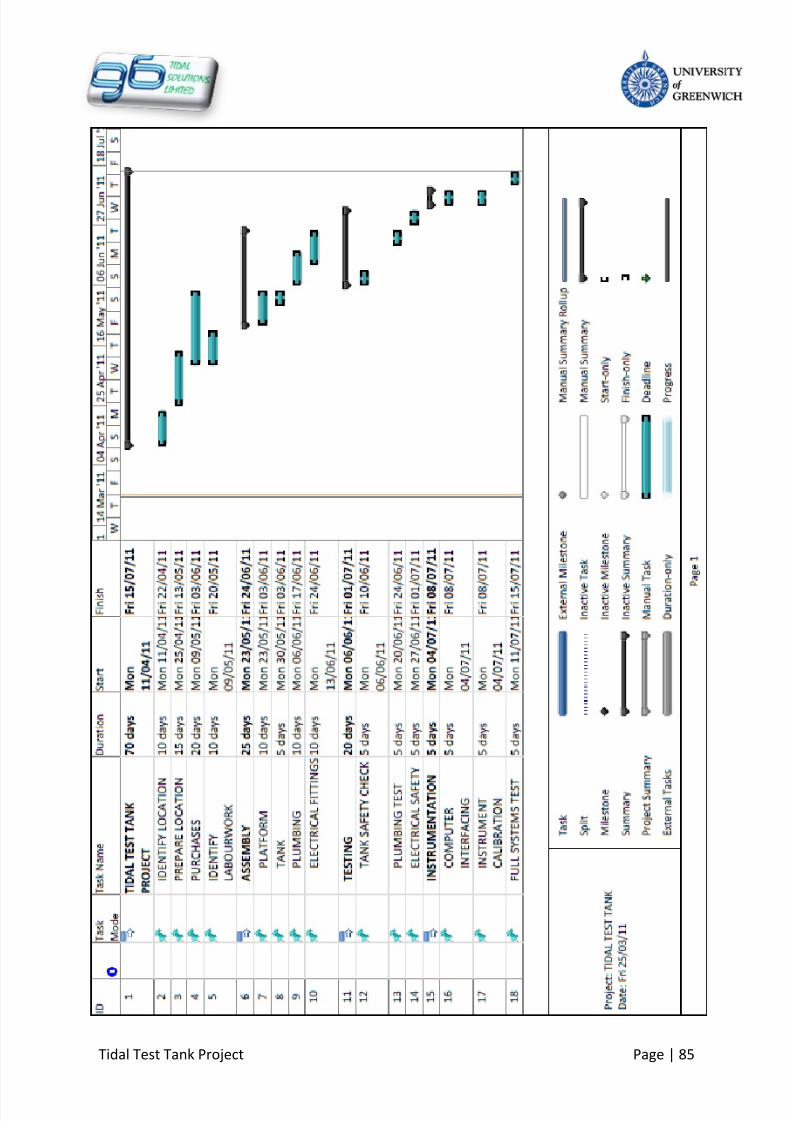
8/10/2019 419 Instrument
http://slidepdf.com/reader/full/419-instrument 92/126
Tidal Test Tank Project Page | 85

8/10/2019 419 Instrument
http://slidepdf.com/reader/full/419-instrument 93/126
Tidal Test Tank Project Page | 86
APPENDIX 2 – TIDAL TANK
SPECIFICATION

8/10/2019 419 Instrument
http://slidepdf.com/reader/full/419-instrument 94/126
Tidal Test Tank Project Page | 87
TIDAL TEST TANK - SPECIFICATION
1.
PRODUCT DESCRIPTION
The tidal test tank is designed to simulate the tidal conditions, primarily of the Medway
River Port but is capable of simulating any tidal environment in the world. This test facility is
capable of testing the loading and unloading effects of ship models up to 2.5m in length.
The tidal movement is controlled by a pump, which is automatically switched by a level
sensor to come on or off as required. The test tank’s Labview PC interface allows full
automatic control of sensors and also provides data logging and analysis capabilities.
Figure 31: Tidal Testing Facility
2. FEATURES
Fully automatic water level control
Platform built around tank to ease use
Electric winch drum provided to aide in ship model placement
Labview PC interface to control sensors and also for data logging and analysis
Electrically and mechanically robust system

8/10/2019 419 Instrument
http://slidepdf.com/reader/full/419-instrument 95/126
Tidal Test Tank Project Page | 88
3. TYPICAL USES
Tidal testing
Water storage
4. TECHNICAL INFORMATION
Specifications
Working fluid Saline and/or fresh water
Max Water level 1m
Operation mode Static and dynamic water flow
Pressure range Up to 1.1 Bar
Typical tide time 1.5 - 2 hoursWater flow method Pumped and gravity feed
Mechanical Information
Mounting Tank bolted together, bolted to platform
Material(s)Tank / Reservoir – Glass Reinforced Polymer
I support beams – steel
Platform - steel
Tank size 3m x 1m x 1mPlatform height 0.7 m
Environmental
Operating temperature 0 – 40oC
Storage temperature Room temperature (about 20 o
C)
Operating pressure range 0 to 1.1 Bar
Noise level 70 dB
Protection class IP68
Electrical and Control
Supply Voltage 230 V/ac
Electrical leads Insulated and connected via control box
Sensor power connection Via step-down transformer and voltage regulator
Step down capacity 240 – 50 V/ac
Standards
Conforms to ISO, CE and BS standards
Examples BS7430, BS7671, BSEN 60529, ISO 7250, ISO 7726, EN547-3
5.
TECHNICAL DRAWINGS

8/10/2019 419 Instrument
http://slidepdf.com/reader/full/419-instrument 96/126
Tidal Test Tank Project Page | 89
GRP Tank Panel GRP Bolted Tank
GRP Reservoir Steel Platform

8/10/2019 419 Instrument
http://slidepdf.com/reader/full/419-instrument 97/126
Tidal Test Tank Project Page | 90
Process Flow Schematic
Control System Schematic
Electrical Connection Schematic
Control Panel (240 ac)Relay switch
Main Supply
Single Phase 240V AC
Relay
1
Relay
5
Relay
4
Relay
3
Relay
2
AC
To
DC
Water Heater
240V/AC
Digital
Thermostat 230V/
ACT
L
F
Water Chiller
(230V/ AC)
Step Down Transformer
240V ac/ 50V ac
Voltage Regulator AC
to DC (12V)
Water Level Sensor
(5-12V/DC)
Temperature Sensor
(5-12V/DC)
Flow Sensor
(4.5 – 24V/DC)
Interface
Emergency
control

8/10/2019 419 Instrument
http://slidepdf.com/reader/full/419-instrument 98/126
Tidal Test Tank Project Page | 91
APPENDIX 3 – TANK
SUPPORT ASSEMBLYDRAWING
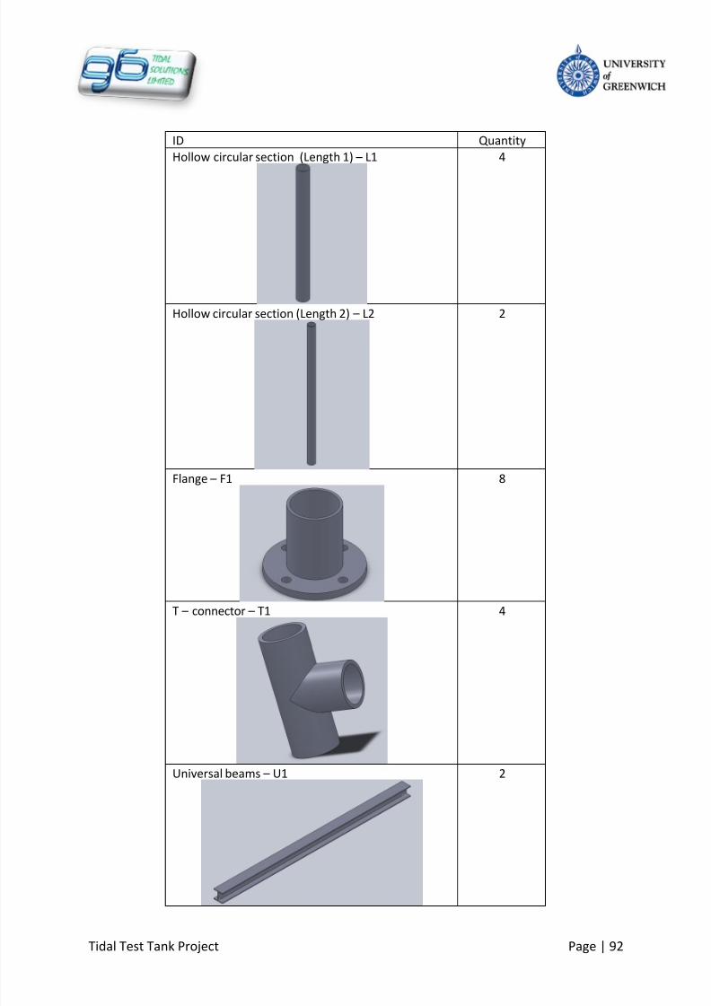
8/10/2019 419 Instrument
http://slidepdf.com/reader/full/419-instrument 99/126
Tidal Test Tank Project Page | 92
ID Quantity
Hollow circular section (Length 1) – L1 4
Hollow circular section (Length 2) – L2 2
Flange – F1 8
T – connector – T1 4
Universal beams – U1 2

8/10/2019 419 Instrument
http://slidepdf.com/reader/full/419-instrument 100/126
Tidal Test Tank Project Page | 93
Nut – N2 -
Bolt – B2 -

8/10/2019 419 Instrument
http://slidepdf.com/reader/full/419-instrument 101/126
Tidal Test Tank Project Page | 94
Step 1
All joint are secured by pre-existing fasteners in each part
Step 2 – Front View
L1
F1
L2
F1T1
U1
B2 N2

8/10/2019 419 Instrument
http://slidepdf.com/reader/full/419-instrument 102/126
Tidal Test Tank Project Page | 95
Step 2 – Side View
The bottom flanges are bolted to the ground to stabilize the whole frame structure
Final tank support assembly
U1
B2 N2

8/10/2019 419 Instrument
http://slidepdf.com/reader/full/419-instrument 103/126
Tidal Test Tank Project Page | 96
APPENDIX 4 – USERPLATFORM DRAWING
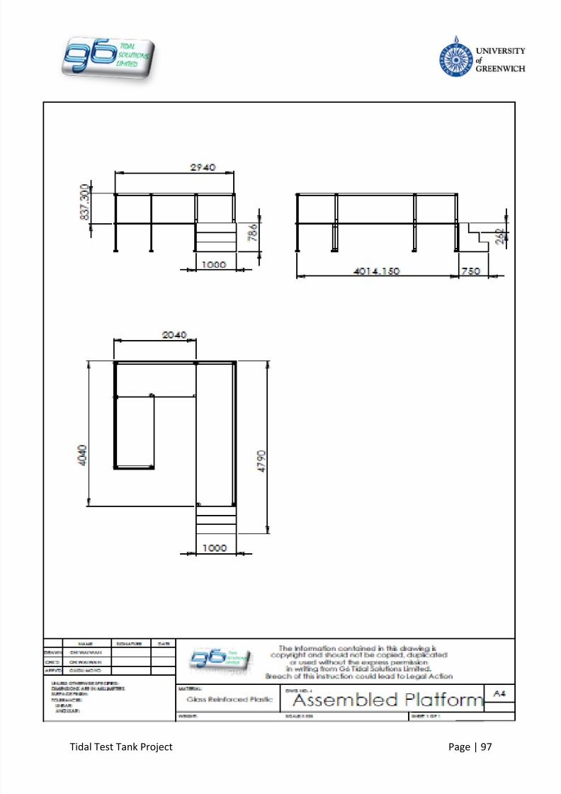
8/10/2019 419 Instrument
http://slidepdf.com/reader/full/419-instrument 104/126
Tidal Test Tank Project Page | 97

8/10/2019 419 Instrument
http://slidepdf.com/reader/full/419-instrument 105/126
Tidal Test Tank Project Page | 98
APPENDIX 5 – SALT WATERCREATION

8/10/2019 419 Instrument
http://slidepdf.com/reader/full/419-instrument 106/126
Tidal Test Tank Project Page | 99
Water Salinity
The Medway River contains brackish water as mentioned before. The salt content in the
water consists of a wide variety of salts and not just sodium chloride. As a result, it has been
decided that marine salt can be used in order to provide the Medway Estuary conditions.
The salt content in brackish water ranges from 5g of salt per litre of fresh water, to 30g of
salt per litre of fresh water. However, to allow for more flexibility of testing conditions,
calculations have been made so that the salinity in the tank can range from fresh water
conditions to sea water conditions.
Instructions for making the salt water in required concentrations from fresh water
1. Ensure entire system empty (test tank, pipe work and reservoir)
2. Make sure all valves to and from the test tank are closed
3. Half fill the tidal test tank ( to the 1500litre mark) with fresh water from the mains
source
4. Raise water temperature to about room temperature.
5. Add the required salt i.e. 5kg to 105kg of salt. Do not handle more than 25kg of salt
at a time.
6. Evenly distribute the salt in the tank to avoid creating a lump of salt collecting one
section of the tank
7. Allow the salt to dissolve till the water is saturated
8. Add the remaining fresh water in intervals, allowing the salt to mix in the water
9.
Fill the tank to the 3000litre mark
10. Check if salt is completely dissolved then distribute the water to the reservoir.
Low Concentration to High Concentration salinity
Example, if concentration is at 10g/l then 30 kg of salt is already in the water, to increase
salinity to 25g/l, simply add a further 45kg of salt to the water in the test tank and allow it to
dissolve

8/10/2019 419 Instrument
http://slidepdf.com/reader/full/419-instrument 107/126
Tidal Test Tank Project Page | 100
Volume of water = 3000litres
Concentration [g/l] Density[kg/m3] Salt Requirements [kg]
5 1005 1510 1010 30
15 1015 45
20 1020 60
25 1025 75
30 1030 90
35 1035 105
Table 12:Table of salinity concentration converted to salt requirements
Suppliers
This is a table of possible suppliers that can be used for the supply of bulk sea salt. If the
same supplier is used on a regular basis, then a contract can be set up in order to reduce the
cost of the salt per unit mass.
Salt Supplier Cost Contact
Kent Reef Salt Coventry Aquatics £1.90 per Kg Tel: (024) 7650 3050
Instant Marine Salt 123 Aquatics £2.00 per Kg Tel: (017) 3346 8677
Sea Salt Summer Naturals £0.90 per Kg Tel:(016) 1338 2256
Red Sea salt Amazon £1.97 per Kg Amazon.co.uk
Caution:
Health and Safety regulations;
o Do not lift more than 25kg of salt at a time.
Allow salt to fully dissolve in the test tank before distributing water through the
piping and pump system to avoid moving solid salt particles.
Note: Evaporation of water from the test tank due to warm conditions in the testing
environment can lead to higher concentrations of salt water as the water evaporates into
the atmosphere.

8/10/2019 419 Instrument
http://slidepdf.com/reader/full/419-instrument 108/126
Tidal Test Tank Project Page | 101
Chart for selecting required amounts of salt for desired concentrations of salinity.
Figure 32: Chart of concentration converted to salt requirements.
0
5
10
15
20
25
30
35
40
45
50
55
60
65
70
75
80
85
90
95
100
105
110
115
0 5 10 15 20 25 30 35 40
S a l t R e q u i r e m e n t [ k g ]
Concentration [g/l]
Concentration to Salt requirement for 3000l of
water
Salt
Linear (Salt)

8/10/2019 419 Instrument
http://slidepdf.com/reader/full/419-instrument 109/126
Tidal Test Tank Project Page | 102
13
APPENDIX 6 –
PERSONAL PROFILES
1. GUGULETHU MOYO
2. OFONAMA ARCHIBONG
3. CHINELO S. IFEJI
4. CHI WAI WAN
5. EVANS WAITHIRA
6. LAYIKUN BERHANU

8/10/2019 419 Instrument
http://slidepdf.com/reader/full/419-instrument 110/126
Tidal Test Tank Project Page | 103
PROFILE
BASIC INFORMATION
Gugulethu Moyo is a BEng Mechanical Engineering
Student.
SWOT ANALYSIS
Strengths Weaknesses
Good decision maker Worrier
Good at planning ahead and setting goals
Highly Analytical
Very supportive in a team role
Conservative
Impatient
Opportunities Threats
Learning from others Developing leadership skills for future
career
May lack motivation sometimes
May clash with team members if they do
not understand the scope of work to be done
Gugulethu is the Team Manager for the Tidal Test Tank project. She also contributed in the
mechanical design of the test tank system and ensured that all the subsystems were able to
join into a function whole.
Name: Gugulethu Moyo
Reference Number: 000471731
Team Role: Team Manager

8/10/2019 419 Instrument
http://slidepdf.com/reader/full/419-instrument 111/126
Tidal Test Tank Project Page | 104
PROFILE
BASIC INFORMATION
Name: Ofonama Archibong
Reference Number: 000478040
Team Role: Assistant Group Manager
Ofonama is a BEng Mechanical Engineering
student. He is a self-motivated individual,
who has gathered a number of useful skills,
both hard and soft during the course of study.
He is currently the Assistant Group Manager
of the Company.
SWOT ANALYSIS
Strengths Weaknesses
Very analytical
Spend too much time on little details
Good researcher of information Could be nervous dealing with crowd
Patient, tolerable and can work with divers
people
Sometimes poor with time
management
Opportunities Threats
Ability to learn from others
Lack of support in tasks could affectproductivity
Learn more by self learning Rival intellectual may pose threat to me
Use analytical skills for group project
Poor time management could affect
productivity
Besides the role of assistant group manager, he also handles all administrative activities of
the group. Lastly, he is part of the group’s Engineering Division handling the roles ofconsultant in mechanical operations and control systems.

8/10/2019 419 Instrument
http://slidepdf.com/reader/full/419-instrument 112/126
Tidal Test Tank Project Page | 105
PROFILE
BASIC INFORMATION
Name: Chinelo S. Ifeji
Reference Number: 000502422
Team Role: Researcher/Business Division
Consultant
Chinelo is a BEng Engineering Business Management student. She is a hard-worker andfocused individual, who has learnt to enjoy challenges and handling multiple jobs during the
course of study.
SWOT ANALYSIS
Strengths Weaknesses
Reliable Do not rely enough on people
Do not rely on her potential
Strict to deadlines Do not take initiative
Sociable Over thinking
Opportunities Threats
Have an understanding how to work in a
team
Overloaded
Learn more about my capabilities Competition between other companies
Improve time management skills
Besides the role of consultant of the Business Division, she is also responsible of the Quality
Control Management and Maintenance Service of the Company.
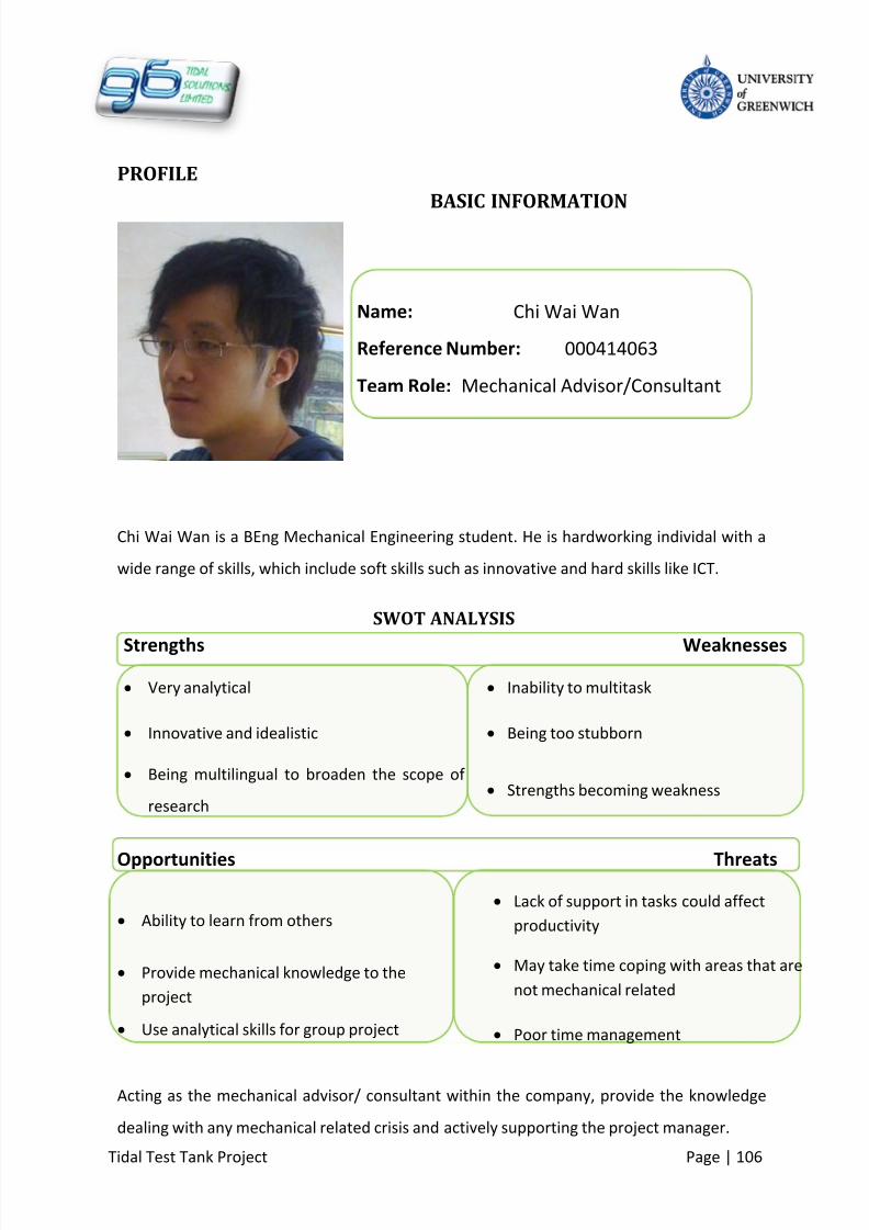
8/10/2019 419 Instrument
http://slidepdf.com/reader/full/419-instrument 113/126
Tidal Test Tank Project Page | 106
PROFILE
BASIC INFORMATION
Name: Chi Wai Wan
Reference Number: 000414063
Team Role: Mechanical Advisor/Consultant
Chi Wai Wan is a BEng Mechanical Engineering student. He is hardworking individal with a
wide range of skills, which include soft skills such as innovative and hard skills like ICT.
SWOT ANALYSIS
Strengths Weaknesses
Very analytical Inability to multitask
Innovative and idealistic Being too stubborn
Being multilingual to broaden the scope of
research Strengths becoming weakness
Opportunities Threats
Ability to learn from others Lack of support in tasks could affect
productivity
Provide mechanical knowledge to the
project
May take time coping with areas that are
not mechanical related
Use analytical skills for group project Poor time management
Acting as the mechanical advisor/ consultant within the company, provide the knowledge
dealing with any mechanical related crisis and actively supporting the project manager.

8/10/2019 419 Instrument
http://slidepdf.com/reader/full/419-instrument 114/126
Tidal Test Tank Project Page | 107
PROFILE
BASIC INFORMATION
Name: Evans Waithira
Reference Number: 000468700
Team Role: Electrical Operations
Mr. Evans is a BEng Electrical and Electronics Engineering
Technology student. Evans being an energetic and
enthusiastic person who enjoys a challenge and
achieving personal goals. He is currently the Electrical
Operations Department also in part of designing the
platform of the Company.
SWOT ANALYSIS
Strengths Weaknesses
Good Listener
Time management
Working under Pressure Overload of work
Being co-operative and punctual. Being distracted
Opportunities Threats
Keen to learn more others
Being late for group meetings
Learn more by self learning Arguments between team colleagues
Gathering information in research. Clashes between work mates

8/10/2019 419 Instrument
http://slidepdf.com/reader/full/419-instrument 115/126
Tidal Test Tank Project Page | 108
PROFILE
BASIC INFORMATION
Name: Layikun Berhanu
Reference Number: 000477587
Team Role: Electrical Operation Adviser
Layikun is a Beng Electrical and Electronics technology
student. He is part of the electrical and control system
consultant department.
SWOT ANALYSIS
Strengths Weaknesses
Gathering resources and information Time management
Communication skills nervous dealing with crowd
Highly motivated whilst working alongside
people Deviate from the main point
Opportunities Threats
Learn from others The tendency to putt other work first
Improvement on different skills Spending more time on one particular point
Share my knowledge with others
Bad Decision Making

8/10/2019 419 Instrument
http://slidepdf.com/reader/full/419-instrument 116/126

8/10/2019 419 Instrument
http://slidepdf.com/reader/full/419-instrument 117/126
Tidal Test Tank Project Page | 110
Peer Review Report, Proforma.
To be completed by each team member, review and feedback on fellow team member’sperformance. Add each of the team members Peer review reports as separate appendixto group report. Complete as proforma instructions.
University of GreenwichMedway School of Engineering
Group DesignPeer Assessment Report
Your Name: GUGULETHU MOYO
Your student number: 000471735
Performance rating guidelines;
Your individual peer assessment for each of your fellow team colleagues should be based upon the following;
0 – 3 = No, or negligible project engagement. Overall team working, low. Contribution towards thecompletion of the project, very low.
4 – 7 = Satisfactory and regular team working engagement. Contributed fully towards the overallcompletion of the project.
8 – 10 = Outstanding and very significant leadership and team working. Contribution throughout the project process beyond the average team mem ber’s requirements.
NB: - Performance rating and comments will be required to be supported by evidence within the respective logbook(s).
Group Member Name
Overallassessmentrating (0 – 10)
Comments (if any)
Chi Wai Wan 8 Brings a different perspective to design process
Ofonama Archibong 9 Puts a lot of effort and diligence into tasks
Evans Waithira 7 Room for improvement on carrying out tasks,however he engaged with the group throughout.
Chinelo Stefania Ifeji 8 Shows dedication to tasks and initiative
Layikun Berhanu 8 Takes initiative and does all required work

8/10/2019 419 Instrument
http://slidepdf.com/reader/full/419-instrument 118/126
Tidal Test Tank Project Page | 111
Peer Review Report, Proforma.
To be completed by each team member, review and feedback on fellow team member’sperformance. Add each of the team members Peer review reports as separate appendixto group report. Complete as proforma instructions.
University of Greenwich
Medway School of Engineering
Group DesignPeer Assessment Report
Your Name: OFONAMA ARCHIBONG
Your student number : 000478040
Performance rating guidelines;
Your individual peer assessment for each of your fellow team colleagues should be based upon the following;
0 – 3 = No, or negligible project engagement. Overall team working, low. Contribution towards thecompletion of the project, very low.
4 – 7 = Satisfactory and regular team working engagement. Contributed fully towards the overallcompletion of the project.
8 – 10 = Outstanding and very significant leadership and team working. Contribution throughout the project process beyond the average team member’s requirements.
NB: - Performance rating and comments will be required to be supported by evidence within the respective logbook(s).
Group Member Name
Overallassessmentrating (0 – 10) Comments (if any)
Gugulethu Moyo 10 She was very instrumental to the team’s efficiency.
Also showed outstanding leadership and ensuredthe team worked in order.
Chinelo S. Ifeji 10 We had our differences, but I do respect herdedication and attitude towards team work. Heroverall contribution to the team was excellent.
Chi Wai Wan 8 His CAD skills were very useful to the team’sdesign process. Overall contribution was great
Evans Waithira 8 Although struggled at the beginning, he did comeout from his comfort zone to contribute his fairquota to the team
Layikun Berhanu 9 He showed dedication to the group work. Therewere highs and lows but his overall contributionwas brilliant

8/10/2019 419 Instrument
http://slidepdf.com/reader/full/419-instrument 119/126
Tidal Test Tank Project Page | 112
Peer Review Report, Proforma.
To be completed by each team member, review and feedback on fellow team member’sperformance. Add each of the team members Peer review reports as separate appendixto group report. Complete as proforma instructions.
University of GreenwichMedway School of Engineering
Group DesignPeer Assessment Report
Your Name: CHINELO STEFANIA IFEJI
Your student number: 000502422
Performance rating guidelines;
Your individual peer assessment for each of your fellow team colleagues should be based upon the following;
0 – 3 = No, or negligible project engagement. Overall team working, low. Contribution towards thecompletion of the project, very low.
4 – 7 = Satisfactory and regular team working engagement. Contributed fully towards the overallcompletion of the project.
8 – 10 = Outstanding and very significant leadership and team working. Contribution throughout the project process beyond the average team member’s requirem ents.
NB: - Performance rating and comments will be required to be supported by evidence within the respective logbook(s).
Group Member Name
Overallassessmentrating (0 – 10)
Comments (if any)
Gugulethu Moyo 9
Ofonama Archibong 9
Chi Wai Wan 8
Layikun Berhanu 8
Evans Waithira 8

8/10/2019 419 Instrument
http://slidepdf.com/reader/full/419-instrument 120/126
Tidal Test Tank Project Page | 113
Peer Review Report, Proforma.
To be completed by each team member, review and feedback on fellow team member’sperformance. Add each of the team members Peer review reports as separate appendixto group report. Complete as proforma instructions.
University of Greenwich
Medway School of Engineering
Group DesignPeer Assessment Report
Your Name: CHI WAI WAN
Your student number: 000414063
Performance rating guidelines;
Your individual peer assessment for each of your fellow team colleagues should be based upon the following;
0 – 3 = No, or negligible project engagement. Overall team working, low. Contribution towards thecompletion of the project, very low.
4 – 7 = Satisfactory and regular team working engagement. Contributed fully towards the overallcompletion of the project.
8 – 10 = Outstanding and very significant leadership and team working. Contribution throughout the project process beyond the average team member’s requirements.
NB: - Performance rating and comments will be required to be supported by evidence within the respective logbook(s).
Group Member Name
Overallassessmentrating (0 – 10)
Comments (if any)
Gugulethu Moyo 10 Hard working group leader Never cease to strive to reach set targets and try tosupport every member in her ability
Chinelo S. Ifeji 9 Bright individual with great contributionKnowledgeable in management/business aspects
Ofonama Archibong 10 Helpful with all memb ers’ task as well as producing great work individually
Layikun Berhanu 9 Excellent work with the electrical aspects of the project. Occasionally presented leadership bydirectly contacting others
Evans Waithira 8 Did working outside his comfort zone, producing good results

8/10/2019 419 Instrument
http://slidepdf.com/reader/full/419-instrument 121/126
Tidal Test Tank Project Page | 114
Peer Review Report, Proforma.
To be completed by each team member, review and feedback on fellow team member’sperformance. Add each of the team members Peer review reports as separate appendixto group report. Complete as proforma instructions.
University of GreenwichMedway School of Engineering
Group DesignPeer Assessment Report
Your Name: EVANS WAITHIRA
Your student number: 000468700
Performance rating guidelines;
Your individual peer assessment for each of your fellow team colleagues should be based upon the following;
0 – 3 = No, or negligible project engagement. Overall team working, low. Contribution towards thecompletion of the project, very low.
4 – 7 = Satisfactory and regular team working engagement. Contributed fully towards the overallcompletion of the project.
8 – 10 = Outstanding and very significant leadership and team working. Contribution throughout the project process beyond the average team member’s require ments.
NB: - Performance rating and comments will be required to be supported by evidence within the respective logbook(s).
Group Member Name
Overallassessmentrating (0 – 10)
Comments (if any)
Gugulethu Moyo 8
Ofonama Archibong 8
Chinelo S. Ifeji 8
Chi Wai Wan 8
Layikun Berhanu 8

8/10/2019 419 Instrument
http://slidepdf.com/reader/full/419-instrument 122/126
Tidal Test Tank Project Page | 115
Peer Review Report, Proforma.
To be completed by each team member, review and feedback on fellow teammember’s performance. Add each of the team members Peer review reports asseparate appendix to group report. Complete as proforma instructions.
University of GreenwichMedway School of Engineering
Group DesignPeer Assessment Report
Your Name: LAYIKUN BERHANU
Your student number: 000477587
Performance rating guidelines;
Your individual peer assessment for each of your fellow team colleagues should be based upon the following;
0 – 3 = No, or negligible project engagement. Overall team working, low. Contribution towardsthe completion of the project, very low.
4 – 7 = Satisfactory and regular team working engagement. Contributed fully towards the overallcompletion of the project.
8 – 10 = Outstanding and very significant leadership and team working. Contributionthroughout the project process beyond the average team member’s re quirements.
NB: - Performance rating and comments will be required to be supported by evidence within the respective logbook(s).
Group Member Name
Overallassessmentrating (0 – 10)
Comments (if any)
Ofonama Archibong 8
Gugulethu Mayo 8
Evans Watithira 8
Chi Wai Wan 8
Chinelo Stefania Ifeji 8

8/10/2019 419 Instrument
http://slidepdf.com/reader/full/419-instrument 123/126
Tidal Test Tank Project Page | 116
14
APPENDIX 8 –
MISCELLANEOUS
DRAWINGS
1. TANK PANELS
2. TANK DRAWING
3. RESERVIOR TANK
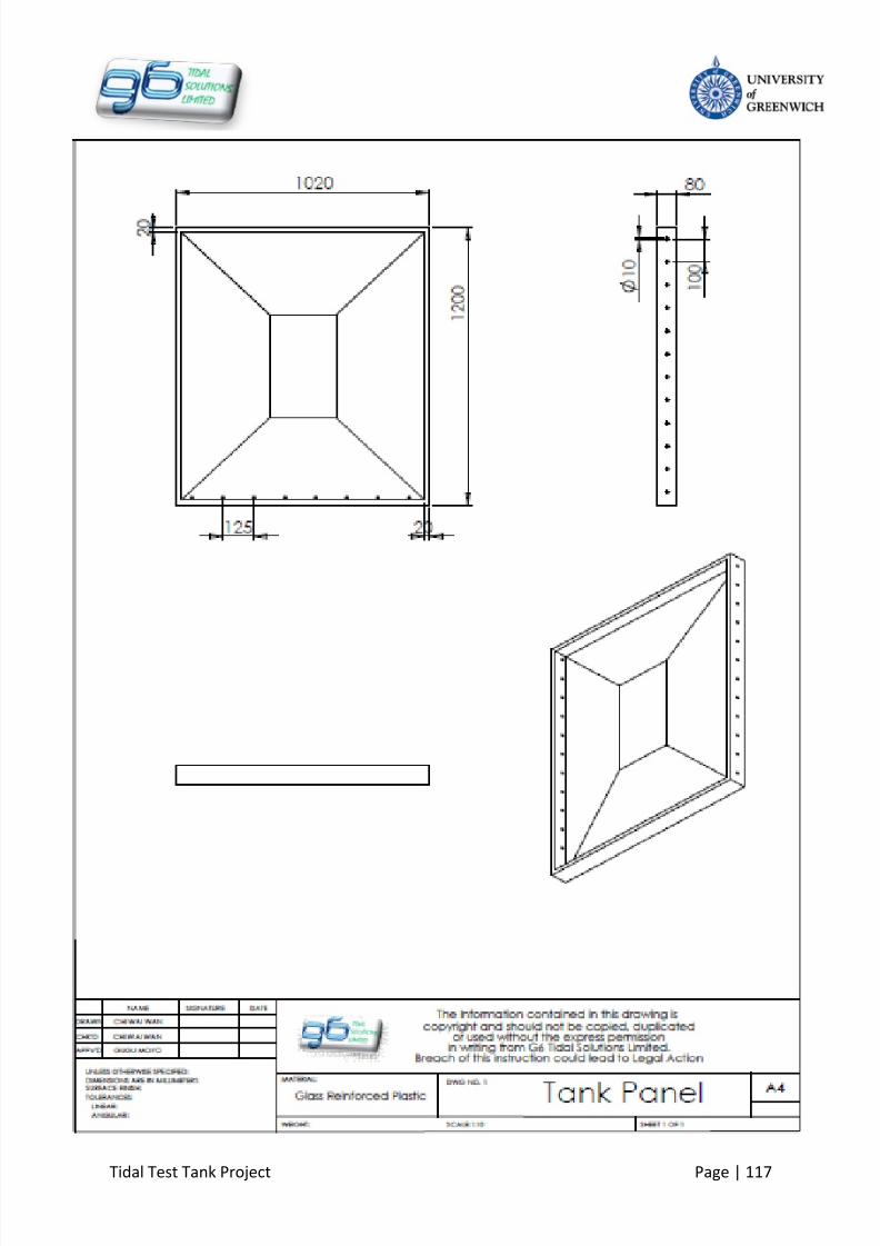
8/10/2019 419 Instrument
http://slidepdf.com/reader/full/419-instrument 124/126
Tidal Test Tank Project Page | 117

8/10/2019 419 Instrument
http://slidepdf.com/reader/full/419-instrument 125/126
Tidal Test Tank Project Page | 118

8/10/2019 419 Instrument
http://slidepdf.com/reader/full/419-instrument 126/126