4.14 thermowells tw - kishore karuppaswamy | … · 2016-05-10 · tance to the point of...
TRANSCRIPT
697
4.14 Thermowells
H. L. DANEMAN
(1995)
B. G. LIPTÁK
(2003)
Applications:
Providing mechanical and corrosion protection for thermal elements and for sightingof radiation pyrometers
Temperature Range:
From cryogenic up to 3500
°
F (1950
°
C)
Materials of Construction:
Carbon steel, 304 or 316 stainless steel, Carpenter 20, Hastelloy B or C, Inconel,Monel, nickel, titanium, glass-lined, or ceramics (alumina or mullite). See Table 4.14gfor a detailed listing of recommended materials for a variety of applications.
Costs:
Steel, 304 or 316 stainless steel well with 0.5 in. (13 mm) NPT threaded connectionand 2.5 in. (64 mm) insertion length costs $25 to $35, while with 10.5 in. (268 mm)insertion length the cost is about $75. Flanged units cost about twice as much. Relativeto stainless steel, the cost multipliers of other well materials are as follows: 1.1 forMonel; 2.0 for Inconel, Carpenter 20, nickel, titanium, and ceramics; and 3.0 forHastelloy B and C.
Partial List of Suppliers:
ABB Inc.-Instrumentation (www.abb.com/us/instrumentation)Barber Colman Industrial Instruments (www.barber-colman.com)Brooklyn Thermometer Co. (www.brooklynthermometer.com)Buffalo Gauge (www.buffalogauge.com)Chino Works America Inc. (www.chinoamerica.com)Conax Buffalo Corp. (www.conaxbuffalo.com)Dresser Instrument (www.dresserinstruments.com)Foxboro-Invensys (www.foxboro.com)H-B Instrumentation (www.hbinstrument.com)Honeywell Industry Solutions (www.iac.honeywell.com)Johnson Controls (www.johnsoncontrols.com)Jumo Process Control (www.jumousa.com)Marsh Bellofram (www.marshbellofram.com)Moeller Instrument Co. (www.moellerinstrument.com)Omega Engineering (www.omega.com)Palmer Instruments (www.palmerinstruments.com)Princo Instruments (www.princoinstruments.com)Sandelius Instruments (www.sandelius.com)Siemens Energy & Automation (www.sea.siemens.com)Tel-Tru Manufacturing Co. (www.teltru.com)Temtex (www.temtex.com)Thermo Electric (www.thermo-electric-direct.com)Trend Instruments (www.trendinst.com)H.O. Trerice (www.hotrerice.com)United Electric (www.ueonline.com)Weiss Instruments (www.weissinstruments.com)Weksler Instruments (www.dresserinstruments.com)WIKA Instrument (www.wika.com)
The purpose of thermowells is to protect the thermal elementsfrom mechanical damage and corrosion or to act as sightingtubes for radiation thermometers. Some of these protective
sockets have already been discussed in other sections of thisvolume. These references include Figure 4.2d in connectionwith bimetallic thermometers; Figure 4.6e in connection with
TW
Flow Sheet Symbol
© 2003 by Béla Lipták

698
Temperature Measurement
filled bulb thermometers; Figure 4.9i in connection withpyrometer sighting tubes, Figure 4.10k in connection withresistance temperature detector protection; and Figures 4.13q,4.13t, and 4.13ee in connection with thermocouple wells. Thediscussion here will build on (but not repeat) what was alreadysaid in connection with the noted figures.
INTRODUCTION
Thermowells permit the removal of thermal elements forcalibration, replacement, or repairs and also allow the use ofportable sensors. The well or protection tube is permanentlyinserted into the pipe or vessel and is secured by threads,flanges, or welds, allowing the thermal element to be insertedinto the well without causing any stress (Figure 4.14a).
THERMOWELL TYPES
Thermowells are usually metallic and may be coated withother materials to provide additional corrosion protection.Integral flanges or threaded sections enable the wells to besecured to the pipe or vessel (Figure 4.14b). Internal threadssecure nipples which extend the head beyond any insulation.It is important to avoid contamination of temperature sensorsby oil (such as cutting oils) left on the inner surface of drilledwells or accumulations of foreign materials within wells.
Protection Tubes
Protection tubes can also be ceramic when used to protectnoble metal thermocouples (TCs) or as sighting tubes forradiation pyrometers. While not as strong as metallic ther-mowells, they do not droop and can withstand higher tem-peratures; in addition, they are free of contamination whichcan cause thermocouple drift due to vapor deposition of ele-ments at higher temperatures. Mullite and high-purity alu-mina are commonly used as ceramic thermowell materials.In addition to being corrosion-resistant, mullite can operateup to 3200
°
F (1750
°
C) and alumina up to 3540
°
F (1950
°
C).When platinum TCs are used at temperatures exceeding2200
°
F (1200
°
C), mullite should not be used, because itcontains impurities that can contaminate platinum. For suchapplications, high-purity alumina is the proper choice.
Dual protection tubes may be used where the outer tubeprovides mechanical protection and the inner tube providescorrosion or permeation protection. See Figure 4.14c for anexample of protective layers used on a high-temperature TC.
The sheaths are either extruded or woven and are usedto protect TCs or other wires. Woven sheaths are similar tothose used for electrical insulation and may be made ofstainless steel, Inconel, tinned copper, fiberglass, or ceramics.They can withstand temperatures up to 2200
°
F (1204
°
C)continuously or 2800
°
F (1538
°
C) for short periods of time.
Sheaths
Extruded sheaths can be plastic or metallic. The metallicsheaths are commonly used for mineral-insulated thermo-couples in which the wire elements are surrounded by
FIG. 4.14a
The test well and its installation.
Cap and Chain
Immersion Length R U Insertion Length
Well LengthA
Insertion Length
1 " (45 mm)Lagging
Extension " (13 mm)NPT(F)
U
" NPT(M)(13 mm)
FIG. 4.14b
Flanged thermowells with tapered and straight shanks. (Courtesyof Trend Instruments Inc.)
Any Flange Size
Any Flange Size
U
U
2 "(57 mm)
"(6.3 mm)
6 "(165 mm)
" NPSM(12.7 mm)
Standard “U” Dimensions:2, 4, 7, 10, 13, 16, and 22"(1" 254 mm)
Bore
B Dia.
Bore +002−000
+002−000
1-1/16"(27 mm)
2 "(57 mm)
"(6.3 mm) " NPSM
(12.7 mm)
© 2003 by Béla Lipták

4.14 Thermowells
699
ceramic oxides such as magnesium oxide (Figure 4.14d).After being packed with powdered oxides, the sheaths areswaged or rolled under pressure to reduce their diameterand tightly pack the powdered insulation. While this pro-cess serves to reduce intrusion of atmosphere within thesheath, it does not protect against humidity or moisture.Moisture intrusion is rapid and deteriorates insulation resis-tance to the point of thermocouple failure. Procedures forinsulation resistance testing are to be found in the AmericanSociety for Testing and Materials documentation. Such test-ing is vital for mineral-insulated, metal-sheathed TCsstored in the open at construction sites or in repair shopsfor periods of time. Sheathing can also cause vapor transferat elevated temperatures, which can result in thermocoupledrift. This is the case with stainless steel sheaths used fornickel-bearing TCs such as types K and N. The offendingelement is manganese, and the problem can be eliminatedby specifying low-manganese Inconel or modified Nicrosilsheathing.
THERMOWELL INSTALLATION
Well installation should be planned so that the wells are readilyaccessible for servicing and the thermal elements can be with-drawn without obstruction by adjacent structures. It is desirableto install spare wells for calibration purposes so the workingsensor can be compared to a standard temperature sensor.
Vertical installation is preferred for very high temperatureuse to prevent sagging. Horizontal installation, on the otherhand, avoids some contamination by foreign materials(Figure 4.14e). In horizontal installations, consideration shouldbe given to the possibility that construction or repair person-nel might misuse the wells as steps.
Immersion Depth
The thermowell immersion depth (U) should be sufficientto eliminate conduction error. A general rule is to use aninsertion length equaling a minimum of 10 times the diameterof the protection tube or well. Another rule of thumb is tohave the sensitive portion of the sensor immersed to a depthof a minimum of 3 in. (75 mm) plus the length of the sensitiveportion. In the case of expansion bulbs, the immersion depthmay be specified by the supplier or can be indicated on acalibration report, if furnished.
For pipe installations, such as steam or hot water lines,insertion in an elbow on the axis of the pipe can permit anappropriate immersion depth should the diameter of the pipe
FIG. 4.14c
Multiple layers of protection used on a high-temperature thermocouple.
FIG. 4.14d
Thermocouple wires surrounded by magnesium oxide or other min-eral insulation and protected by an integral metal sheath of stainlesssteel or Inconel.
Primary Cermet Well Permeable to O2, CO, CO2, H2 above 330 kPa
Secondary Sheath, Permeable toH2 Only (Disilicide-Coated Molybdenum)
Refractory Magnesium OxideInsulation
W5Re/W26ReRefractory Element Thermocouple
Not Affected by H2
3 3
1
FIG. 4.14e
Flanged thermowell designs used on erosive services.
1
MachinedTip
Slip-on Reducing Flange
To be Specified
8"
Construction
Straight Taper-6"
Machined TipVessel Wall
Bevel for Welding
1" Schedule80 Pipe
2" Schedule80 Pipe
1" LubricatedPlug Valve2" Weld Neck Flange to Vessel Specification
InstallationNote:Valve Provided to Shear Thermocouple and Shut Off Leak inEvent of Thermowell Failure
" Thick SteelRetaining Ring
Lining
1" Schedule 80Seamless PipeWeld
1" ASA STD B2.1Tapered Pipe Thread
SealWeld
Weld
2"
38"
38" 1
32"
78"
±2"
45°
(1" = 25.4 mm)
© 2003 by Béla Lipták
be inadequate (Figure 4.14f).

700
Temperature Measurement
When installing thermowells at an angle or in elbows, itis hard to maintain sanitary conditions, which is an importantconsideration in the food and pharmaceutical industries.
Thermowells inserted into small pipes can also cause exces-sive flow restrictions, pressure drops, or even plugging.
Thermowell Time Constants
The time constant of a thermal element increases with itsmass. If time constants of a couple of seconds or less arerequired, unprotected, small diameter, and bare thermal ele-ments must be used. The addition of even a thin-walledsheath or thermowell increases the time constant to about 5s as a minimum, and with larger bulbs it can reach 30 s. Itis also important to maintain positive contact between thethermal element and the well in order to make sure that thetemperature being measured reflects the temperature of theprocess on the outside and not the air temperature on theinside of the well.
If the process gases include hydrogen and a filled thermalelement is used, it might be a good idea to vent the well,since hydrogen can damage the filling material.
In Table 4.14g, well material recommendations are givenfor a variety of services.
FIG. 4.14f
Alternate ways of installing thermowells in pipes that are 3 in. (75 mm)or smaller in diameter.
1
Hex Bushing
70°
60°
TABLE 4.14g
Selection Guide for Thermowell Materials
2
Application Thermowell Material Application Thermowell Material
Heat Treating
AnnealingUp to 704
°
C (1300
°
F)Over 704
°
C (1300
°
F)
Carburizing hardeningUp to 816
°
C (1500
°
F)1093
°
C (1500 to 2000
°
F)Over 1093
°
C (2000
°
F)
Nitriding salt baths
CyanideNeutralHigh speed
Iron and Steel
Basic oxygen furnace
Blast furnacesDowncomerStove domeHot blast mainStove trunkStove outlet flue
Open hearthFlues and stackCheckersWaste heat boiler
Black steelInconel 600,
a
Type 446 SS
Black steel, Type 446 SSInconel 600, Type 446 SSCeramic
b
Type 446 SSNickel (CP)Type 446 SSCeramic
b
Quartz
Inconel 600, Type 446 SSSilicon carbideInconel 600Inconel 600Black steel
Inconel 600, Type 446 SSInconel 600, CermetsInconel 600, Type 446 SS
Iron and Steel cont.
Billet heating slab heating andbutt weldingUp to 1093
°
C (2000
°
F)Over 1093
°
C (2000
°
F)
Bright annealing batchTop work temperature
Bottom work temperature
Continuous furnace sectionForgingSoaking pits
Up to 1093
°
C (2000
°
F)Over 1093
°
C (2000
°
F)
Nonferrous Metals
AluminumMeltingHeat treatingBrass or bronze
LeadMagnesiumTinZincPickling tanks
Inconel 600, Type 446 SSSilicon ceramic carbide
Not required (use bare type J thermocouple)
Type 446 SS
Inconel 600, ceramic
b
Silicon carbide, ceramic
b
Inconel 600, Silicon ceramic carbide
b
Cast iron (white-washed)Black steelNot required (use dip-type
thermocouple)Type 446 SS, black steelBlack steel, cast ironExtra heavy carbon steelExtra heavy carbon steelChemical lead
© 2003 by Béla Lipták

4.14 Thermowells
701
TABLE 4.14g (Continued)
Selection Guide for Thermowell Materials
2
Application Thermowell Material Application Thermowell Material
Cement
Exit fluesKilns, heating zone
Ceramic
Kilns DryersVitreous enameling
Glass
Fore hearths and feedersLehrsTanks
Roof and wallFlues and checkers
Paper
Digesters
Petroleum
Dewaxing
Towers
Transfer lines
Factioning column
Bridgewall
Power
Coal-air mixtures
Flue gases
Preheaters
Steel lines
Water lines
Boiler tubes
Gas Producers
Producer gas
Water gasCarburetorSuperheaterTar stills
Incinerators
Up to 1093
°
C (2000
°
F) Over 1093
°
C (2000
°
F)
Inconel 600, Type 446 SSInconel 600
Ceramic
b
and silicon carbide
c
Silicon carbide, black steelInconel 600, Type 446 SS
Platinum thimbleBlack steel
Ceramic
a
Inconel 600, Type 446 SS
Type 316 SS, Type 446 SS
Types 304, 310, 316, 321, 347 SS, carbon steel
Types 304, 310, 316, 321, 347 SS,carbon steel
Types 304, 310, 316, 321, 347 SS, carbon steel
Types 304, 310, 316, 321, 347 SS, carbon steel
Types 304, 310, 316, 321, 347 SS, carbon steel
304 SS
Black steel, Type 446 SS
Black steel, Type 446 SS
Types 347 or 316 SS
Low carbon steels
Type 304, 309, or 310 SS
Type 446 SS
Inconel 600, Type 446 SSInconel 600, Type 446 SSLow carbon steels
Inconel 600, Type 446 SSCeramic (primary), silicon carbide (secondary)
a
Food
Baking ovens
Charretort, sugar
Vegetables and fruit
Chemical
Acetic acid10 to 50% 21
°
C (70
°
F)50% 100
°
C (212
°
F)99% 21 to 100
°
C (70 to 212
°
F)
Alcohol, ethyl, methyl21 to 100
°
C (70 to 212
°
F)
AmmoniaAll concentrations 21
°
C (70
°
F)
Ammonium chlorideAll concentrations 100
°
C (212
°
F)
Ammonium nitrateAll concentrations 21 to 100
°
C (70 to 212
°
F)Ammonium sulphate, 10% to
saturated 100
°
C (212
°
C)
Barium chloride, all concentrations 21
°
C (70
°
F)
Barium hydroxide, all concentrations, 21
°
C (70
°
F)
Barium sulphite
Brines
Bromine
Butadiene
Butane
Butyl acetate
Butyl alcohol
Calcium chlorate, dilute, 21 to 66
°
C (70 to 150
°
F)
Calcium hydroxide10 to 20% 100
°
C (212
°
F)50% 100
°
C (212
°
F)
Carbolic acid, all, 100
°
C (212
°
F)
Carbon dioxide, wet or dry
Chlorine gas
Dry, 21
°
C (70
°
F)Moist, 7 to 100
°
C (20 to 212
°
F)
Chromic acid, 10 to 50% 100
°
C (212
°
F)
Citric acid15% 21
°
C (70
°
F)
Black steel
Black steel
Type 304 SS
Type 304, Hastelloy C,
d
Monel
Type 316, Hastelloy C,
d
MonelType 430, Hastelloy C,
d Monel
Type 304
Types 304, 316 SS
Types 316 SS, Monel
Type 316 SS
Type 316 SS
Monel, Hastelloy C
Low carbon steels
Nichrome,a Hastelloy C
Monel
Tantalum, Monel
Type 304 SS
Type 304 SS
Monel
copper, Type 304 SS
Type 304 SSType 304 SS, Hastelloy CType 316 SS, Hastelloy C
Type 316 SS
2017-T4 aluminum, Monel, nickel
Type 316 SS, MonelHastelloy C
Type 316 SS, Hastelloy C (all concentrations)
Type 304, SS, Hastelloy C (all concentrations)
© 2003 by Béla Lipták
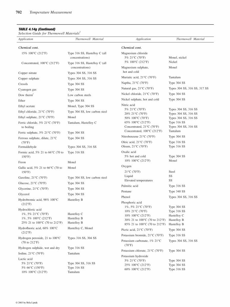
702 Temperature Measurement
TABLE 4.14g (Continued)Selection Guide for Thermowell Materials2
Application Thermowell Material Application Thermowell Material
Chemical cont.
15% 100°C (212°F)
Concentrated, 100°C (212°F)
Copper nitrate
Copper sulphate
Cresols
Cyanogen gas
Dow thermf
Ether
Ethyl acetate
Ethyl chloride, 21°C (70°F)
Ethyl sulphate, 21°C (70°F)
Ferric chloride, 5% 21°C (70°F) to boiling
Ferric sulphate, 5% 21°C (70°F)
Ferrous sulphate, dilute, 21°C (70°F)
Formaldehyde
Formic acid, 5% 21 to 66°C (70 to 150°F)
Freon
Gallic acid, 5% 21 to 66°C (70 to 150°F)
Gasoline, 21°C (70°F)
Glucose, 21°C (70°F)
Glycerine, 21°C (70°F)
Glycerol
Hydrobromic acid, 98% 100°C(212°F)
Hydrochloric acid1%, 5% 21°C (70°F)1%, 5% 100°C (212°F)25% 21 to 100°C (70 to 212°F)
Hydrofluoric acid, 60% 100°C (212°F)
Hydrogen peroxide, 21 to 100°C (70 to 212°F)
Hydrogen sulphide, wet and dry
Iodine, 21°C (70°F)
Lactic acid5% 21°C (70°F)5% 66°C (150°F)10% 100°C (212°F)
Type 316 SS, Hastelloy C (all concentrations)
Type 316 SS, Hastelloy C (all concentrations)
Types 304 SS, 316 SS
Types 304 SS, 316 SS
Type 304 SS
Type 304 SS
Low carbon steels
Type 304 SS
Monel, Type 304 SS
Type 304 SS, low carbon steel
Monel
Tantalum, Hastelloy C
Type 304 SS
Type 304 SS
Types 304 SS, 316 SS
Type 316 SS
Monel
Monel
Type 304 SS, low carbon steel
Type 304 SS
Type 304 SS
Type 304 SS
Hastelloy B
Hastelloy CHastelloy BHastelloy B
Hastelloy C, Monel
Types 316 SS, 304 SS
Type 316 SS
Tantalum
Type 304 SS, 316 SSType 316 SSTantalum
Chemical cont.
Magnesium chloride5% 21°C (70°F)5% 100°C (212°F)
Magnesium sulphate, hot and cold
Muriatic acid, 21°C (70°F)
Naptha, 21°C (70°F)
Natural gas, 21°C (70°F)
Nickel chloride, 21°C (70°F)
Nickel sulphate, hot and cold
Nitric acid5% 21°C (70°F)20% 21°C (70°F)50% 100°C (70°F)65% 100°C (212°F)Concentrated, 21°C (70°F)Concentrated, 100°C (212°F)
Nitrobenzene 21°C (70°F)
Oleic acid, 21°C (70°F)Oleum, 21°C (70°F)
Oxalic acid5% hot and cold10% 100°C (212°F)
Oxygen
21°C (70°F)LiquidElevated temperatures
Palmitic acid
Pentane
Phenol
Phosphoric acid1%, 5% 21°C (70°F)10% 21°C (70°F)10% 100°C (212°F)30% 21 to 100°C (70 to 212°F)85% 21 to 100°C (70 to 212°F)
Picric acid, 21°C (70°F)
Potassium bromide, 21°C (70°F)
Potassium carbonate, 1% 21°C(70°F)
Potassium chlorate, 21°C (70°F)
Potassium hydroxide5% 21°C (70°F)25% 100°C (212°F)60% 100°C (212°F)
Monel, nickelNickel
Monel
Tantalum
Type 304 SS
Types 304 SS, 316 SS, 317 SS
Type 304 SS
Type 304 SS
Types 304 SS, 316 SSTypes 304 SS, 316 SSTypes 304 SS, 316 SSType 316 SSTypes 304 SS, 316 SSTantalum
Type 304 SS
Type 316 SSType 316 SS
Type 304 SSMonel
SteelSSSS
Type 316 SS
Type 340 SS
Types 304 SS, 316 SS
Type 304 SSType 316 SSHastelloy CHastelloy BHastelloy B
Type 304 SS
Type 316 SS
Types 304 SS, 316 SS
Type 304 SS
Type 304 SSType 304 SSType 316 SS
© 2003 by Béla Lipták

4.14 Thermowells 703
References
1. American Petroleum Institute, Manual on Installation of RefineryInstruments, API RP 550, 1965.
2. American Society for Testing and Materials, Manual on the Use ofThermocouples in Temperature Measurement, STP 470B, WestConshocken, PA, 1981.
Bibliography
Adler, C.B., “Reliability Aspects of Temperature Measurement,” InstrumentSociety of America Conference, 2001.
American Society of Mechanical Engineers Boiler and Pressure Vessel Code,Section VIII, New York, 1965.
American Society for Testing and Materials Annual Book of ASTM Stan-dards, Part 44, West Conshocken, PA, 1980.
TABLE 4.14g (Continued)Selection Guide for Thermowell Materials2
Application Thermowell Material Application Thermowell Material
Chemical cont.
Potassium nitrate5% 21°C (70°F)5% 100°C (212°F)
Potassium permanganate, 5% 21°C (70°F)
Potassium sulphate, 5% 21°C (70°F)
Potassium sulphide, 21°C (70°F)
Propane
Pyrogallic acid
Quinine bisulphate, dry
Quinine sulphate, dry
Seawater
Salicylic acid
Sodium bicarbonateAll concentrations, 21°C (70°F)5% 66°C (150°F)
Sodium carbonate, 5% 21 to 66°C (70 to 150°F)
Sodium chloride5% 21 to 66°C (70 to 150°F)
Saturated, 21 to 100°C (70 to212°F)
Sodium fluoride, 5% 21°C (70°F)
Sodium hydroxide
Sodium hypochlorite, 5% still
Sodium nitrate, fused
Sodium peroxide
Type 304 SSType 304 SS
Type 304 SS
Types 304 SS, 316 SS
Types 304 SS, 316 SS
Type 304 SS, low carbon steel
Type 304 SS
Type 316 SS
Type 304 SS
Monel or Hastelloy C
Nickel
Type 304 SSTypes 304 SS, 316 SSTypes 304 SS, 316 SS
Type 316 SS
Type 316 SS, Monel
Monel
Types 304 SS, 316 SS, Hastelloy C
Type 316 SS, Hastelloy C
Type 316 SS
Type 304 SS
Chemical cont.
Sodium sulphate, 21°C (70°F)
Sodium sulphide, 21°C (70°F)
Sodium sulphite, 30% 66°C (150°F)
Sulphur dioxideMoist gas, 21°C (70°F)Gas, 302°C (575°F)
SulphurDry moltenWet
Sulphuric acid5% 21 to 100°C (70 to 212°F)10% 21 to 100°C (70 to 212°F)50% 21 to 100°C (70 to 212°F)90% 21°C (70°F)90% 100°C (212°F)
Tannic acid, 21°C (70°F)
Tartaric acid21°C (70°F)66°C (150°F)
Toluene
Turpentine
Whiskey and wine
Xylene
Zinc chloride
Zinc sulphate5% 21°C (70°F)Saturated, 21°C (70°F)25% 100°C (212°F)
Types 304 SS, 316 SS
Type 316 SS
Type 304 SS
Type 316 SSTypes 304 SS, 316 SS
Type 304 SSType 316 SS
Hastelloy B, 316 SSHastelloy BHastelloy BHastelloy BHastelloy D
Type 304 SS, Hastelloy B
Type 304 SSType 316 SS
2017-T4 aluminum, low carbon steel
Types 304 SS, 316 SS
Type 304 SS, nickel
Copper
Monel
Types 304 SS, 316 SSTypes 304 SS, 316 SSTypes 304 SS, 316 SS
a Trademark of the International Nickel Co.b Due to susceptibility to cracking, sudden thermal shocks should be avoided.c Due to susceptibility to cracking, sudden thermal shocks should be avoided.d Trademark of the Cabot Corp.e Trademark of the Driver-Harris Co.f Trademark of the Dow Chemical Corp.
© 2003 by Béla Lipták

704 Temperature Measurement
Bluestein, I., “Understanding Contact Temperature Sensors,” Sensors, October2001.
Gordon Co., Temperature Measurement Handbook.JMS Southeast, Inc. JMS Southeast Co. Catalog, Statesville, NC.Johnson, R., “Measuring the Hot, Difficult and Inaccessible,” Control Engi-
neering, June 2001.Magison, E., “Temperature Measurement,” InTech, October 25, 2001.Masek, J.A., “Thermowell Design for Process Piping,” Hydrocarbon Pro-
cessing, February 1964.
Michalski, L. et al., Temperature Measurement, 2nd ed., London: John Wiley& Sons, 2001.
Nicholas, J.V. and White, D.R., Traceable Temperature, New York: JohnWiley & Sons, 1982.
OMEGA Engineering Inc., Complete Temperature Handbook and Encyclo-pedia, Stamford, CT, 1989.
Thermo Electric Co., Temperature Measurement Designers’ Guide, RochellePark, NJ.
Volbrecht, A. and Gordon, W., “Temperature Measurement: Making Senseof it All,” Sensors, June 1998.
© 2003 by Béla Lipták