40mpha high wall ductless system sizes 09 to 24 · high wall ductless system sizes 09 to 24. 2...
TRANSCRIPT
Specifications subject to change without notice.
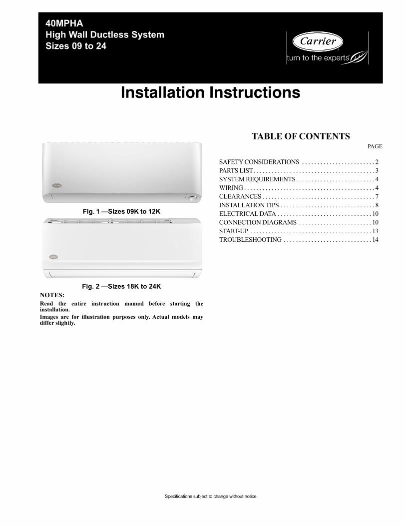
Fig. 1 —Sizes 09K to 12K
Fig. 2 —Sizes 18K to 24KNOTES:Read the entire instruction manual before starting theinstallation.Images are for illustration purposes only. Actual models maydiffer slightly.
TABLE OF CONTENTSPAGE
SAFETY CONSIDERATIONS . . . . . . . . . . . . . . . . . . . . . . . . 2PARTS LIST. . . . . . . . . . . . . . . . . . . . . . . . . . . . . . . . . . . . . . . . 3SYSTEM REQUIREMENTS. . . . . . . . . . . . . . . . . . . . . . . . . . 4WIRING . . . . . . . . . . . . . . . . . . . . . . . . . . . . . . . . . . . . . . . . . . . 4CLEARANCES . . . . . . . . . . . . . . . . . . . . . . . . . . . . . . . . . . . . . 7INSTALLATION TIPS . . . . . . . . . . . . . . . . . . . . . . . . . . . . . . . 8ELECTRICAL DATA . . . . . . . . . . . . . . . . . . . . . . . . . . . . . . . 10CONNECTION DIAGRAMS . . . . . . . . . . . . . . . . . . . . . . . . 10START-UP . . . . . . . . . . . . . . . . . . . . . . . . . . . . . . . . . . . . . . . . 13TROUBLESHOOTING . . . . . . . . . . . . . . . . . . . . . . . . . . . . . 14
Installation Instructions
40MPHAHigh Wall Ductless SystemSizes 09 to 24

2 Specifications subject to change without notice. 40MPHA-02SI
SAFETY CONSIDERATIONSInstalling, starting up, and servicing air-conditioning equipmentcan be hazardous due to system pressures, electrical components,and equipment location (roofs, elevated structures, etc.).Only trained, qualified installers and service mechanics shouldinstall, start-up, and service this equipment.Untrained personnel can perform basic maintenance functions suchas coil cleaning. All other operations should be performed bytrained service personnel only.When working on the equipment, observe the precautions in theliterature and on tags, stickers, and labels attached to theequipment.Follow all safety codes. Wear safety glasses and work gloves. Keepa quenching cloth and a fire extinguisher nearby when brazing.Use care in handling, rigging, and setting bulky equipment.Read these instructions thoroughly and follow all warnings orcautions included in literature and attached to the unit. Consultlocal building codes and National Electrical Code (NEC) forspecial requirements. Recognize safety information.
This is the safety-alert symbol . When you see this symbol onthe unit and in instructions or manuals, be alert to the potential forpersonal injury. Understand these signal words: DANGER,WARNING, and CAUTION. These words are used with thesafety-alert symbol. DANGER identifies the most serious hazardswhich will result in severe personal injury or death. WARNINGsignifies hazards which could result in personal injury or death.CAUTION is used to identify unsafe practices which may result inminor personal injury or product and property damage.NOTE is used to highlight suggestions which will result inenhanced installation, reliability, or operation.
ELECTRICAL SHOCK HAZARDFailure to follow this warning could result in personalinjury or death.Before installing, modifying, or servicing system, mainelectrical disconnect switch must be in the OFFposition. There may be more than 1 disconnect switch.Lock out and tag switch with a suitable warning label.
WARNING
ELECTRICAL SHOCK HAZARDFailure to follow this warning could result in death, serious personal injury, and/or property damage. Never use air or gases containing oxygen for leak testing or operating refrigerant compressors. Pressurized mixtures of air or gases containing oxygen can lead to an explosion.
WARNING
EQUIPMENT DAMAGE HAZARDFailure to follow this caution may result in equipmentdamage or improper operation.Do not bury more than 36 in. (914 mm) of refrigerant pipein the ground. If any section of pipe is buried, there must bea 6 in. (152 mm) vertical rise to the valve connections onthe outdoor units. If more than the recommended length isburied, refrigerant may migrate to the cooler buried sectionduring extended periods of system shutdown. This causesrefrigerant slugging and could possibly damage thecompressor at start-up.
CAUTION

40MPHA-02SI Specifications subject to change without notice. 3
PARTS LIST
Table 1: Parts List
Fig. 3 — Parts ListNOTES:
If the outdoor unit is higher than the indoor unit, prevent rain from flowing into the indoor unit along the connection pipe bymaking a downward arc in the connection pipe before it enters the wall to the indoor unit. This ensures that rain drips from theconnection pipe before it enters the wall.Piping and the interconnecting wiring are field supplied.Figure 3 is only a sketch. Different models may be slightly different.
The following units are covered in these installation instructions.
Table 2 — Unit Sizes
PART NAME QUANTITYIndoor Unit 1Wall Mounting Plate 1Wall Mounting Screw A ST3.9x25 5Anchor 5Air Filter 2Wireless Remote Controller 1Wireless Remote Controller Holder 1Remote Controller Mounting Screw B (ST2.9x10) 1Battery AAA.LR03 2Multi-function board (installed on the front panel) 2Flare nuts for liquid and gas pipes 1Installation Instructions Manual 1Owner's manual 1Warranty Card 1Drain Adapter 1Stencil 1Wi-Fi USB Dongle 1
Wall Mounting Plate
Refrigerant PipingSignal Cable
Remote Control
Drainage Pipe
Louver
Remote Control Holder
Functional Filter
Front Panel
Occupancy Sensor(Only Sizes 09-12)
Timer
Boost
DESCRIPTION kBTUh V-Ph-Hz OUTDOOR MODEL
High Wall Heat Pump
9 208/230-1-60 40MPHAQ09XA312 208/230-1-60 40MPHAQ12XA318 208/230-1-60 40MPHAQ18XA324 208/230-1-60 40MPHAQ24XA3
4 Specifications subject to change without notice. 40MPHA-02SI
SYSTEM REQUIREMENTSAllow sufficient space for airflow and service of the unit. See Fig. 4 for the required minimum distances between the unit, walls or ceilings.
Piping
IMPORTANT: Both refrigerant lines must be insulated separately.Table 3 lists the pipe sizes for the indoor unit. Refer to the outdoor unit installation instructions for other allowed piping lengths andrefrigerant information.
Table 3 — Indoor Unit Pipe Sizes
All outdoor units have an electronic expansion valve to manage the refrigerant flow of the fan coil connected.
WIRINGAll wires must be sized per NEC (National Electrical Code) orCEC (Canadian Electrical Code) and local codes. Use ElectricalData table MCA (minimum circuit amps) and MOCP (maximumover current protection) to correctly size the wires and thedisconnect fuse or breakers respectively.
Recommended Connection Method for Power and Communication WiringThe main power is supplied to the outdoor unit. The field supplied14/3 stranded wire with ground with a 600 volt insulation rating,power/communication wiring from the outdoor unit to indoor unitconsists of four (4) wires and provides the power for the indoorunit. Two wires are line voltage AC power, one is communicationwiring (S) and the other is a ground wire. Wiring between indoorand outdoor unit is polarity sensitive. The use of BX wire is NOTrecommended.If installed in a high Electromagnetic field (EMF) area andcommunication issues exists, a 14/2 stranded shielded wire can beused to replace L2 and (S) between outdoor unit and indoor unitlanding the shield onto ground in the outdoor unit only.
UNIT SIZE 9K (208-230V) 12K (208-230V) 18K (208-230V) 24K (208-230V)
Gas Pipe
In. 3/8 1/2 5/8 5/8(mm) 9.52 12.7 15.9 15.9
Liquid Pipe
In. 1/4 1/4 3/8 3/8(mm) 6.35 6.35 9.52 9.52
EQUIPMENT DAMAGE HAZARDFailure to follow this caution may result in equipmentdamage or improper operation.
Wires should be sized based on NEC and local codes.
CAUTION
EQUIPMENT DAMAGE HAZARDFailure to follow this caution may result in equipment damageor improper operation. Be sure to comply with local codes while running wire fromthe indoor unit to the outdoor unit. Every wire must be connected firmly. Loose wiring maycause the terminal to overheat or result in unit malfunction. Afire hazard may also exist. Ensure all wiring is tightlyconnected. No wire should touch the refrigerant tubing, compressor orany moving parts.Disconnecting means must be provided and shall be locatedwithin sight and readily accessible from the air conditioner.Connecting cable with conduit shall be routed through thehole in the conduit panel.
CAUTION
40MPHA-02SI Specifications subject to change without notice. 5
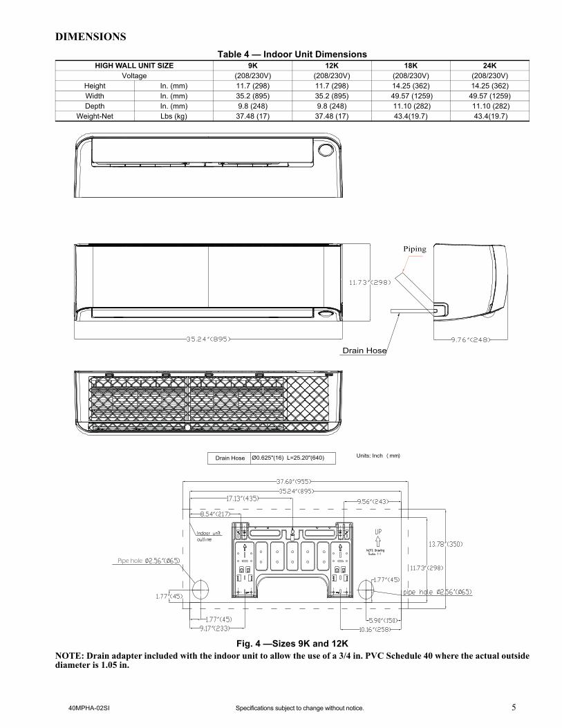
DIMENSIONS
Table 4 — Indoor Unit Dimensions
Fig. 4 —Sizes 9K and 12KNOTE: Drain adapter included with the indoor unit to allow the use of a 3/4 in. PVC Schedule 40 where the actual outsidediameter is 1.05 in.
HIGH WALL UNIT SIZE 9K 12K 18K 24KVoltage (208/230V) (208/230V) (208/230V) (208/230V)
Height In. (mm) 11.7 (298) 11.7 (298) 14.25 (362) 14.25 (362) Width In. (mm) 35.2 (895) 35.2 (895) 49.57 (1259) 49.57 (1259) Depth In. (mm) 9.8 (248) 9.8 (248) 11.10 (282) 11.10 (282)
Weight-Net Lbs (kg) 37.48 (17) 37.48 (17) 43.4(19.7) 43.4(19.7)
Piping
Drain Hose
Drain Hose Ø0.625"(16) L=25.20"(640)
Pipe hole

6 Specifications subject to change without notice. 40MPHA-02SI
DIMENSIONS (CONT)
Fig. 5 —Sizes 18K and 24K
Piping
Drain Hose

40MPHA-02SI Specifications subject to change without notice. 7
CLEARANCES
Fig. 6 —Unit ClearancesNOTE: The top clearance recommended for proper return airflow is 5.9in (15cm). Reduction of this clearance maydecrease the performance of these units. This may be reduced to 3.2in (80mm) as long as the right and left clearances areachieved.
4.75 in(12 cm) min.
6 ft (1.8m)
CEILING
FLOOR
5.9in. (15cm) min.
4.75 in(12 cm) min.

8 Specifications subject to change without notice. 40MPHA-02SI
INSTALLATION TIPSIdeal installation locations include:
Indoor Unit
• A location where there are no obstacles near inlet and outlet area.• A location which can bear the weight of indoor unit.• Do not install indoor units near a direct source of heat such as
direct sunlight or a heating appliance.• A location which provides appropriate clearances (see Fig. 6).
INDOOR UNIT INSTALLATION
Fig. 7 —High Wall Unit
Prior to InstallationBefore installing the indoor unit, ensure the compatibility with theOutdoor unit using the product data as a reference.
Select the Installation Location:
Before installing the indoor unit, choose an appropriate location.The following are standards that should help you choose anappropriate location for the unit. Proper installation locations mustmeet the following standards:
1. Good air circulation2. Convenient drainage3. Noise from the unit will not disturb others4. Firm and solid—the location will not vibrate5. A site strong enough to support the weight of the unit6. A location at least 3.28 ft. (1m) from all other electrical devices
(e.g., TV, radio, computer)7. DO NOT install the unit in the following locations:
a. Near any source of heat, steam, or combustible gasb. Near flammable items such as curtains or clothingc. Near any obstacle that might block air circulationd. Near the doorwaye. In a location subject to direct sunlight
NOTE: Wall Holes: If there is no fixed refrigerant piping.While choosing a location, you should leave ample room for awall hole (refer to the Drill wall hole for connective piping step)for the signal cable and refrigerant piping that connect theindoor and outdoor units. The default position for all piping isthe right side of the indoor unit (while facing the unit). However,the unit can accommodate piping to both the left and right.
Attach the Mounting Plate to the Wall:
1. Carefully remove the mounting plate, which is attached to theback of the indoor unit.
2. Using the Stencil, determine the wall hole position. The mountingplate should be located horizontally and level on the wall. Allminimum spacings shown in Fig. 6 should be maintained.
3. If the wall is block, brick, concrete or similar material, drill 0.2”(5 mm) diameter holes and insert anchors for the appropriatemounting screws.
4. Attach the mounting plate to the wall.
Mounting Plate Dimensions
Different model sizes have different mounting plates. Ensurethere’s enough room to mount the indoor unit (refer to Figures 4 and5). The following measurements can be located on these figures:• Width of mounting plate• Height of mounting plate• Width of indoor unit relative to plate• Height of indoor unit relative to plate• Recommended position of wall hole (both to the left and right of
mounting plate)• Relative distances between screw holes.
Fig. 8 —Mounting Plate Orientation
DRILL HOLE IN WALL FOR THE INTERCONNECTING PIPING, DRAIN AND WIRING
Refrigerant Line Routing
The refrigerant lines may be routed in any of the four directionsshown in Fig. 10. For maximum serviceability, it is recommended tohave refrigerant line flare connections and the drain connections onthe outside of the wall that the fan coil will be mounted on.
If piping is going through the back:• Determine the pipe hole position using the mounting plate as a
template. Drill pipe hole diameter per values given in Figures 4and 5. The outside pipe hole is 1/2-in. (13 mm) min. lower thaninside pipe hole, so it slants slightly downward (see Fig. 9).
Fig. 9 —Drill HolesIf piping is going through the right or left side:• Use a small saw blade to carefully remove the corresponding
plastic covering on side panel and drill the appropriate size holewhere the pipe is going through the wall.
Fig. 10 —Piping Locations
Correct orientation of the Mounting Plate
1/2 in. (13 mm)Min.
INDOOR OUTDOOR
Pipe holder
Pipe cover
Right piping
Left piping
Pipe cover
Right back piping
Left back piping
1 2
3
4

40MPHA-02SI Specifications subject to change without notice. 9
Prepare the Refrigerant Piping
The refrigerant piping is inside an insulating sleeve attached to theback of the unit. You must prepare the piping before passing itthrough the hole in the wall.
NOTE: (Piping Angle) Refrigerant piping can exit theindoor unit from four different angles facing the front ofthe unit (see Fig. 11):
1. Left-hand side2. Left rear3. Right-hand side4. Right rear
Fig. 11 —Piping Angle
If the refrigerant piping is already embedded in the wall, perform thefollowing steps:
1. Hook the top of the indoor unit on the upper hook of the mountingplate. Keep in mind that the hooks on the mounting plate aresmaller than the holes on the back of the unit. If you find that youdo not have ample room to connect the embedded pipes to theindoor unit, the unit can be adjusted left or right by about 1.25-1.95in. (30-50mm), depending on the model (see Fig. 12).
Fig. 12 —Hook Indoor Unit to Mounting Plate2. Use the holders in the mounting plate to prop up the unit, allowing
you enough space to connect the refrigerant piping, signal cable,and the drain hose.
Fig. 13 —Use Holder to Prop up the Unit3. Connect the drain hose and refrigerant piping.4. Keep the pipe connection point exposed to perform the leak test.5. After the leak test, wrap the connection point with insulation tape.6. If the holders (see step 2.) are being used to prop out the unit, be
sure to fold and latch them completely into the mounting plate.Remove any other bracket or wedge that is propping out the unit.
7. Using even pressure, push down on the bottom half of the unit.Keep pushing down until the unit snaps onto the hooks along thebottom of the mounting plate.
If there is no refrigerant piping embedded in the wall, perform thefollowing steps:
1. Based on the position of the wall hole relative to the mountingplate, choose the side from which the piping will exit the unit.
2. If the wall hole is behind the unit, keep the knock-out panel inplace. If the wall hole is to the side of the indoor unit, remove theplastic knock-out panel from that side of the unit (see Fig. 11).This creates a slot through which your piping can exit the unit.Use needle nose pliers if the plastic panel is too difficult toremove by hand.
Fig. 14 —Knock-out Panel3. Use scissors to cut down the length of the insulating sleeve to
reveal about 1.57in. (40mm) of the refrigerant piping. This servesmultiple purposes:a. To facilitate the refrigerant piping connection process b. To facilitate Gas Leak Checks and enable you to check
for kinks in the copper tubing.
4. Connect the indoor unit’s refrigerant piping to the connectivepiping (line set) that joins the indoor and outdoor units.
5. Based on the position of the wall hole relative to the mountingplate, determine the necessary angle of your piping.
6. Grip the refrigerant piping at the base of the bend.7. Slowly, with even pressure, bend the piping towards the hole. Do
not kink or damage the piping during the process.
(1)
(2)
(3)
(4)
ELECTRICAL OPERATION HAZARDBe extremely careful not to dent or damage the piping whilebending them away from the unit. Any dents in the pipingwill affect the unit’s performance.
WARNING
Move to left or right
30-50mm(1.2-1.95in)
30-50mm(1.2-1.95in)
Knock-out Panel

10 Specifications subject to change without notice. 40MPHA-02SI
ELECTRICAL DATA
Table 5 — Electrical Data
LEGENDFLA- Full Load Amps
CONNECTION DIAGRAMS
Fig. 15 —Connection DiagramsNOTES:
1. Do not use thermostat wire for any connection between indoor and outdoor units.2. All connections between indoor and outdoor units must be as shown. The connections are sensitive to polarity and will result in a fault code.
TERMINAL BLOCK LOCATION
1. Open the front panel of the indoor unit.2. Using a screwdriver, open the wire box cover on the right side of
the unit, then open the terminal block cover. This will reveal theterminal block.
Fig. 16 —Terminal Block Location
Fig. 17 —Control and Power Wiring on the Indoor Unit
HIGH WALL UNIT SIZEINDOOR FAN MAX FUSE CB AMP
V-Ph-Hz FLA HP
Refer to outdoor unit installation instructions –Indoor unit powered by the outdoor unitHeat Pump Models
9K
208/230-1-60
0.34 0.02712K 0.34 0.02718K 0.5 0.08224K 0.5 0.082
SL1 L2
208/230-1-60
Main Power Supply
L1 L2 S L1 L2
CONNECTING CABLEOUTDOOR TO INDOOR
Indoor UnitPower Supply
208/230-1-60
Indoor SignalHighVoltage
GND
Ground
Power toIndoor Unit
Indoor SignalHighVoltage
208/230-1-60FIELD POWER SUPPLY
GND
208/230-1-60
208-230V Indoor Unit 208-230V Outdoor Unit
Wire box cover
Screw
Screw
Terminal block
cover
Cable clamp
L1 L2 S
208/230V

40MPHA-02SI Specifications subject to change without notice. 11
INSTALL ALL POWER, INTERCONNECTING WIRING, AND PIPING TO THE INDOOR UNIT
1. Run interconnecting piping and wiring from outdoor unit toindoor unit.
2. Run interconnecting cable through hole in wall (outside to inside).3. Lift indoor unit into position and route piping and drain through
hole in wall (inside to outside). Fit the interconnecting wiring intoback side of indoor unit.
4. Put upper claw at back of indoor unit on upper hook of MountingPlate, move indoor unit from side to side to see that it is securelyhooked.
5. Open the indoor unit’s front panel by loosening the screws, whichprovides a large space for wiring connection.
6. Open the wire box cover to connect the cable.7. Pull interconnecting wire up from back of indoor unit and
position in close to the terminal block on indoor unit.8. Push lower part of indoor unit up on wall, then move indoor unit
from side to side, up and down to check if it is hooked securely(see Fig. 18).
Fig. 18 —Indoor Unit Installation9. Connect wiring from outdoor unit per connection diagram (see
Fig. 15 and Fig. 16).10. Replace the wire cover on the front of the unit, and the plastic
panel on the back.
Pipinga. Cut the pipe, with a pipe cutter, at 90 degrees (see Fig. 19).b. Remove the service connection, if provided with the unit.
Fig. 19 —Pipe Cuttingc. Remove all the burrs from the cut cross section of the
pipe avoiding any burrs inside the tubes.d. d. Remove the flare nuts attached to the indoor and
outdoor units.e. Install the correct size flare nut onto the tubing and make
the flare connection. Refer to Table 6 for flare spacing.
Table 6 — Flare Spacing
Fig. 20 —Flare Spacingf. Apply a small amount of refrigerant oil to the flare
connection on the tubing.g. Align center of the pipes and/or service valve.
Fig. 21 —Align Pipe Centerh. Connect both the liquid and gas piping to the indoor uniti. Tighten the flare nut using a torque wrench as specified in
Table 7.
Table 7 — Tightening Torque
Fig. 22 —Tighten the Flare NutFor additional diagnostic information, refer to the Service Manual.
Refrigerant tubes and indoor coil should be evacuated using therecommended deep vacuum method of 500 microns. The alternatetriple evacuation method may be used if the procedure outlinedbelow is followed. Always break a vacuum with dry nitrogen.
OUTER DIAM. INCH (MM)
A INCH (MM)MAX. MIN.
Ø 1/4” (6.35) 0.05 (1.3) 0.03 (0.7)Ø 3/8” (9.52) 0.06 (1.6) 0.04 (1.0)Ø 1/2” (12.7) 0.07 (1.8) 0.04 (1.0)
Ø 5/8” (15.88) 0.09 (2.2) 0.08 (2.0)
Upper hook
Lower hook
90 Roughness BurrSlanted
PIPE DIAMETER INCH (MM)TIGHTENING TORQUE
Ft-lb N-mØ1/4” (6.35) 10 to 13 13.6 to 17.6Ø3/8” (9.52) 24 to 31 32.5 to 42.0Ø1/2” (12.7) 37 to 46 50.1 to 62.3
Ø5/8” (15.88) 50 to 60 67.7 to 81.3
Bar
Copper pipe
Clamp handleRed arrow mark
Cone
Yoke
Handle
Bar"A"
Indoor unit tubing Flare nut Piping
Flare nut
Copper tube
UNIT DAMAGE HAZARDFailure to follow this caution may result in equipmentdamage or improper operation.Never use the system compressor as a vacuum pump.
WARNING

12 Specifications subject to change without notice. 40MPHA-02SI
FINAL TUBING CHECK
IMPORTANT: Ensure certain factory tubing on theindoor unit has not shifted during shipment. Ensure tubesare not rubbing against each other or any sheet metal.Pay close attention to feeder tubes, making sure wire tieson feeder tubes are secure and tight.
DRAIN CONNECTIONSConnect the drain line. The drain line must not have a trap anywherein its length, must pitch downwards, and must be insulated up to theoutside wall (see Fig. 20). By default, the drain hose is attached tothe left-hand side of unit (when facing the back of the unit).However, it can also be attached to the right-hand side.
a. To ensure proper drainage, attach the drain hose on thesame side that your refrigerant piping exits the unit.
b. Attach a drain hose extension (purchased separately) tothe end of drain hose.
c. Wrap the connection point firmly with Teflon tape toensure good seal and to prevent leaks.
d. For the portion of the drain hose that remains indoors,e. Wrap it with foam pipe insulation to prevent
condensation.f. Remove the air filter and pour a small amount of water
into the drain pan to ensure that water flows from the unitsmoothly.
Plug the Unused Drain Hole
To prevent unwanted leaks you must plug the unused drain hole withthe rubber plug provided.
Fig. 23 —Proper Drain Hose InstallationNOTE: For proper orientation of the refrigerant piping,electrical cable and drain lines, refer to Fig. 21.
Fig. 24 —Bundle drain hose, refrigerant pipes, & signal cable
NOTE: For applications where gravity cannot be used fordrainage, a condensate pump accessory is available.Consult the condensate pump Installation Instructions formore information.
WIRELESS REMOTE CONTROL INSTALLATION
Mounting Bracket (if installed on the wall)
1. Use the two screws supplied with the wireless remote controllerto attach the mounting bracket to the wall in a location selected bythe customer and within operating range.
2. Install the batteries in the remote controller.3. Place the remote controller into the remote controller mounting
bracket.
NOTE: For remote controller operation, refer to the unitOwner’s Manual.
WIRED REMOTE CONTROLLER INSTALLATIONFor setup instructions, refer to the wired controller installationmanual.
1. Use the multi-function board mounted on the front panel.
Fig. 25 —Multi-Function Board2. Disassemble the Multi-Function Board.
Fig. 26 —Multi-Function Board3. Open the multi-function board to make the wiring connection.
Fig. 27 —Multi-Function Board
retaw otni dne niard tup ton oDreporP Do not form a rise
Indoor Unit
Space behind unit
Refrigerant piping
Drain hoseSignal wire
Insulation tape

40MPHA-02SI Specifications subject to change without notice. 13
4. Cut the female plug from the cable supplied with the wiredremote controller and strip the wires to connect to the Multi-Function board.
Fig. 28 —Cut the female plug and strip the wires5. Connect the wired remote controller cable to the multi-function
board using:a. X—Brownb. (2.) Y—Yellowc. (3.) E—Black (ground)d. (4.) 5V—Red (power)
Fig. 29 —Connect the cable to the board6. Re-install the multi-function board on the bracket located on the
front panel.
Fig. 30 —Install the multi-function board
START-UP
Test Operation
Perform a test operation after completing gas leak and electricalsafety check (see Fig. 28).
1. Push “ON/OFF” on the remote controller to begin testing.
NOTE: A protection feature prevents air conditionerfrom being activated for approximately 3 to 4 minutes.
2. Push MODE, select COOLING, HEATING, FAN mode tocheck that all functions work correctly.
3. To run the test using the MANUAL button in the indoor unit:a. Open front panel of the indoor unit;b. Push the manual switch once to energize the unit. The set
conditions of manual operation are as follows:· Preset set point: 76F (24C)· Fan speed: AUTO· Discharge air direction: Pre-set position based on operation in “COOL” or “HEAT” mode.
4. Be sure to set manual switch to “OFF” (by pushing it twice again)after finishing test operation.
NOTE: If the ambient temperature is below 63F (17C).The remote controller can not be used to turn on theCOOL function when the ambient temperature is below63F (17C). In this instance, the MANUAL CONTROLbutton can be used to test the COOL function.
1. MANUAL CONTROL is located on the right-hand side of thedisplay box located on the front panel of the indoor unit (see Fig.31). Press the button two times to select the COOL function.Perform a Test Run as normal.
Fig. 31 —Test operation
Manual Control Button
AUTO/COOL

Copyright 2018 Carrier D 3300 Riverview Parkway Atlanta GA, 30339 Edition Date: 12/18 Catalog No. 40MPHA-02SI
Manufacturer reserves the right to discontinue, or change at any time, specifications or designs without notice and without incurring obligations. Replaces: 40MPHA-01SI
SYSTEM CHECKS1. Conceal the tubing where possible.2. Ensure the drain tube slopes downward along its entire length.3. Ensure all tubing and connections are properly insulated.4. Fasten tubes to the outside wall, when possible.5. Seal the hole through which the cables and tubing pass.
INDOOR UNIT1. Do all remote controller buttons function properly?2. Do the display panel lights work properly?3. Does the air deflection louver function properly?4. Does the drain work?
Explain Following Items To Customer (with the aid of theOwner’s Manual):
1. How to turn air conditioner on and off; selecting COOLING,HEATING and other operating modes; setting a desiredtemperature; setting the timer to automatically start and stop airconditioner operation; and all other features of the remote controland display panel.
2. How to remove and clean the air filter.3. How to set air deflection louver.4. Explain care and maintenance.5. Present the Owner’s Manual and installation instructions to
customer.
TROUBLESHOOTINGFor ease of service, the systems are equipped with diagnostic code display LEDs on both the indoor and outdoor units. The indoor diagnosticdisplay is a combination of flashing LEDs on the display panel or the front of the unit.Some indoor units display error codes specifying failure modes in outdoor units. If possible, always check the diagnostic codes displayed onthe indoor unit first.The diagnostic codes displayed in the indoor and outdoor units are listed in Table 8.
INDOOR UNIT DIAGNOSTIC GUIDES
Table 8 — Unit Diagnostic Guides
For additional diagnostic information, refer to the Service Manual.
DISPLAY LED STATUSE0 Indoor unit EEPROM hardware errorE1 Indoor / outdoor units communication errorE2 Zero-crossing signal detection errorE3 Indoor fan speed has been out of controlE4 Indoor room temperature sensor T1 open circuit or short circuitE5 Evaporator coil temperature sensor T2 open circuit or short circuitEA Indoor unit EEPROM parameter errorEb Communication error between the indoor PCB and display boardEc Refrigerant leakage detectionEf Intelligent eye module errorF1 Outdoor ambient temperature sensor T4 open circuit or short circuitF2 Condenser coil temperature sensor T3 open circuit or short circuitF3 Compressor discharge temperature sensor TP open circuit or short circuitF4 Outdoor unit EEPROM parameter errorF5 Outdoor fan speed has been out of controlF6 Temperature sensor T2B (Located on the outdoor pipe) open circuit or short circuitP0 IPM malfunction or IGBT over-strong current protection
P11/P10 Over voltage or over low voltage protectionP2 High temperature protection of IPM moduleP4 Inverter compressor drive errorP6 Low pressure protection (Only for the outdoor unit with pressure switch)