40” plug aerator - tractor supply company · 2020-03-12 · your aerator is now fully assembled...
TRANSCRIPT
40” Plug Aerator
Model# AE-40T
11122010
Page 1
Pre-assembly Instructions: For best results, follow all directions step by step. Read entire step instructions first, and then proceed with the set up. Open all boxes before beginning to assemble and check parts and hardware. HELPFUL TIP: Read ALL instructions before starting to assemble.
Check Parts and Hardware:
Group together and check that all hardware and parts are included. Refer to parts and hardware illustrations below.
If you are missing parts, contact Customer Service at 218-943-6296 for missing hardware or parts.
Recommended Tools for Assembly: 1 each – Combination Wrench 10mm, 11 mm, 12mm, 13mm, 19mm (one ratcheting for faster work) 1 – Adjustable Wrench – Medium Size 1 – Medium Size Pliers 1 – Tape Measure may be useful to measure parts
PARTS LISTINGS:
NOTE: Parts #9 & #11 below will be assembled for this model
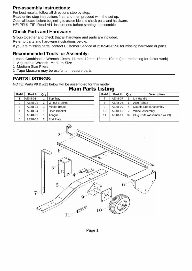
Main Parts Listing
Ref# Part # Qty Description
1 AE48-01 1 Top Tray
2 AE48-02 3 Wheel Bracket
3 AE48-03 1 Middle Brace
4 AE48-04 1 Hitch Bracket
5 AE48-05 1 Tongue
6 AE48-06 2 End Plate
Ref# Part # Qty Description
7 AE48-07 1 Lift Handle
8 AE48-08 1 Axle / Shaft
9 AE48-09 4 Double Spool Assembly
10 AE48-10 2 Wheel Assembly
11 AE48-11 32 Plug Knife (assembled w/ #9)
Page 2
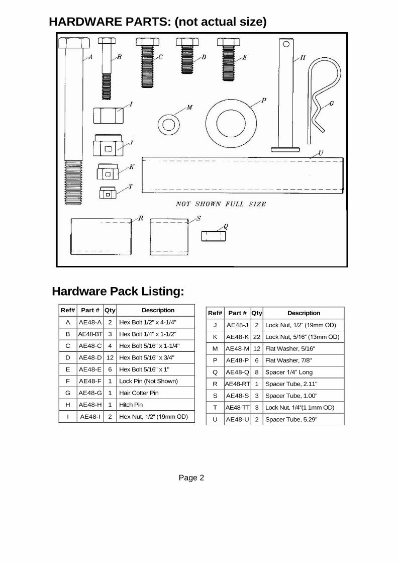
HARDWARE PARTS: (not actual size)
Hardware Pack Listing:
Ref# Part # Qty Description
A AE48-A 2 Hex Bolt 1/2" x 4-1/4"
B AE48-BT 3 Hex Bolt 1/4" x 1-1/2"
C AE48-C 4 Hex Bolt 5/16" x 1-1/4"
D AE48-D 12 Hex Bolt 5/16" x 3/4"
E AE48-E 6 Hex Bolt 5/16" x 1"
F AE48-F 1 Lock Pin (Not Shown)
G AE48-G 1 Hair Cotter Pin
H AE48-H 1 Hitch Pin
I AE48-I 2 Hex Nut, 1/2“ (19mm OD)
Ref# Part # Qty Description
J AE48-J 2 Lock Nut, 1/2“ (19mm OD)
K AE48-K 22 Lock Nut, 5/16“ (13mm OD)
M AE48-M 12 Flat Washer, 5/16"
P AE48-P 6 Flat Washer, 7/8"
Q AE48-Q 8 Spacer 1/4” Long
R AE48-RT 1 Spacer Tube, 2.11"
S AE48-S 3 Spacer Tube, 1.00"
T AE48-TT 3 Lock Nut, 1/4“(1 1mm OD)
U AE48-U 2 Spacer Tube, 5.29"
Page 3
Assembly Instructions:
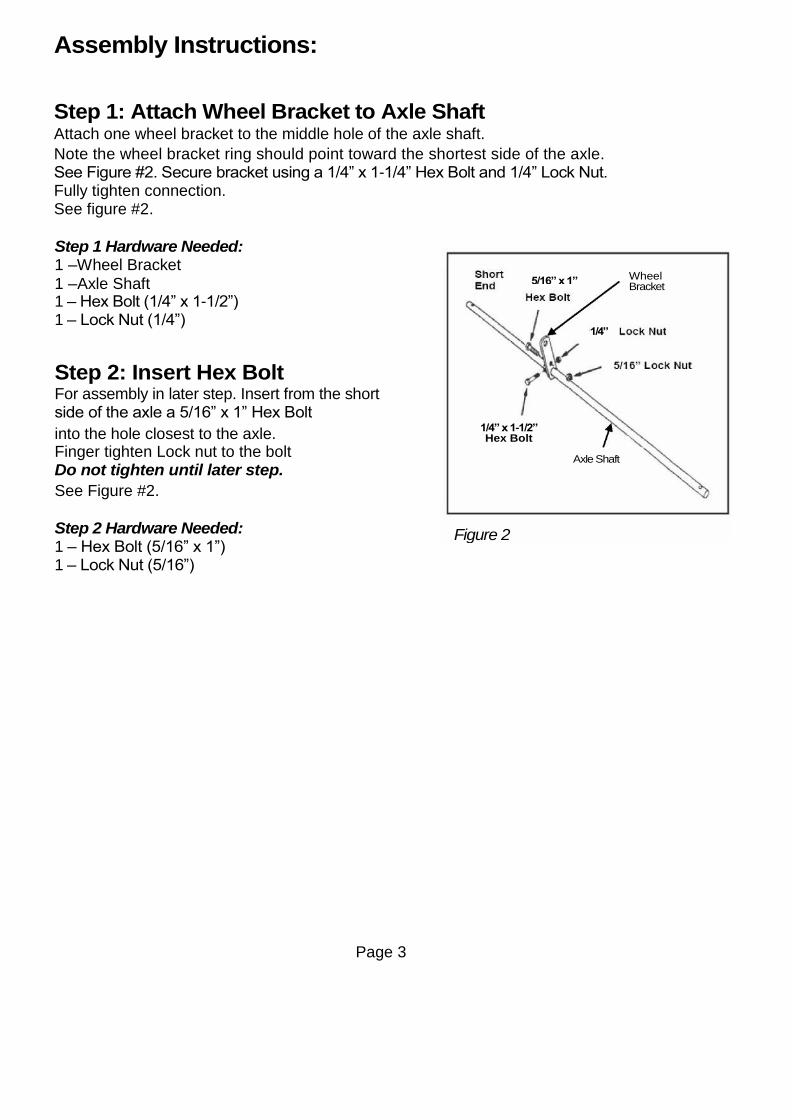
Step 1: Attach Wheel Bracket to Axle Shaft Attach one wheel bracket to the middle hole of the axle shaft.
Note the wheel bracket ring should point toward the shortest side of the axle. See Figure #2. Secure bracket using a 1/4” x 1-1/4” Hex Bolt and 1/4” Lock Nut. Fully tighten connection. See figure #2.
Step 1 Hardware Needed: 1 –Wheel Bracket
1 –Axle Shaft 1 – Hex Bolt (1/4” x 1-1/2”) 1 – Lock Nut (1/4”)
Step 2: Insert Hex Bolt For assembly in later step. Insert from the short side of the axle a 5/16” x 1” Hex Bolt
into the hole closest to the axle. Finger tighten Lock nut to the bolt Do not tighten until later step.
See Figure #2.
Step 2 Hardware Needed: 1 – Hex Bolt (5/16” x 1”) 1 – Lock Nut (5/16”)
Wheel Bracket
5/16” x 1”
1/4”
1/4” x 1-1/2” Hex Bolt
Axle Shaft
Figure 2

Page 4
Step 3: Assemble Short Side of Axle Shaft Assemble below items onto short side of the axle shaft in the following order. Note the plugger knives should face out 1. Start with one double spool
2. 5.29” spacer tube 3. Double spool 4. 1” spacer tube
5. Flat washer (7/8”) See figure #3.
Step 3 Hardware Needed: 2 – Double spools 1 – 5.29” spacer tube 1 – 1” spacer tube
1 – Flat washer (7/8”)
Step 4: Assemble Long Side of Axle Shaft Assemble these items onto LONG SIDE of the axle shaft in the following order. Plugger knives can face same direction when assembled.
1. Start with 1” spacer tube
2. 7/8” flat washer
3. Middle Brace
4. 7/8” flat washer 5. 2.11” spacer tube 6. Double spool assembly 7. 5.29” spacer tube
8. Double spool assembly 9. 1” spacer tube
10. 7/8” flat Washer
See Figure #4 for detail
Step 4 Hardware Needed:
1 – Middle brace 2 – Double spools 1 –2.11” spacer tube 1 – 5.29” spacer tube 2 – 1” spacer tube 3 – Flat washer (7/8”)
Figure 3
2. 11” Long
Figure 4
Page 5
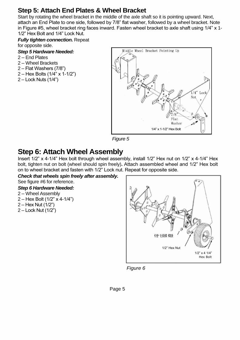
Step 5: Attach End Plates & Wheel Bracket Start by rotating the wheel bracket in the middle of the axle shaft so it is pointing upward. Next, attach an End Plate to one side, followed by 7/8” flat washer, followed by a wheel bracket. Note in Figure #5, wheel bracket ring faces inward. Fasten wheel bracket to axle shaft using 1/4” x 1-1/2” Hex Bolt and 1/4” Lock Nut.
Fully tighten connection. Repeat for opposite side.
Step 5 Hardware Needed:
2 – End Plates 2 – Wheel Brackets 2 – Flat Washers (7/8”) 2 – Hex Bolts (1/4” x 1-1/2”) 2 – Lock Nuts (1/4”)
Figure 5
Step 6: Attach Wheel Assembly Insert 1/2” x 4-1/4” Hex bolt through wheel assembly, install 1/2” Hex nut on 1/2” x 4-1/4” Hex bolt, tighten nut on bolt (wheel should spin freely). Attach assembled wheel and 1/2” Hex bolt on to wheel bracket and fasten with 1/2” Lock nut. Repeat for opposite side.
Check that wheels spin freely after assembly. See figure #6 for reference.
Step 6 Hardware Needed: 2 – Wheel Assembly 2 – Hex Bolt (1/2” x 4-1/4”) 2 – Hex Nut (1/2”) 2 – Lock Nut (1/2”)
Figure 6
1/4” x 1-1/2” Hex Bolt
1/2” Lock Nut 1/2” Lock Nut
1/2” Hex Nut
1/2” x 4 1/4”
Hex Bolt
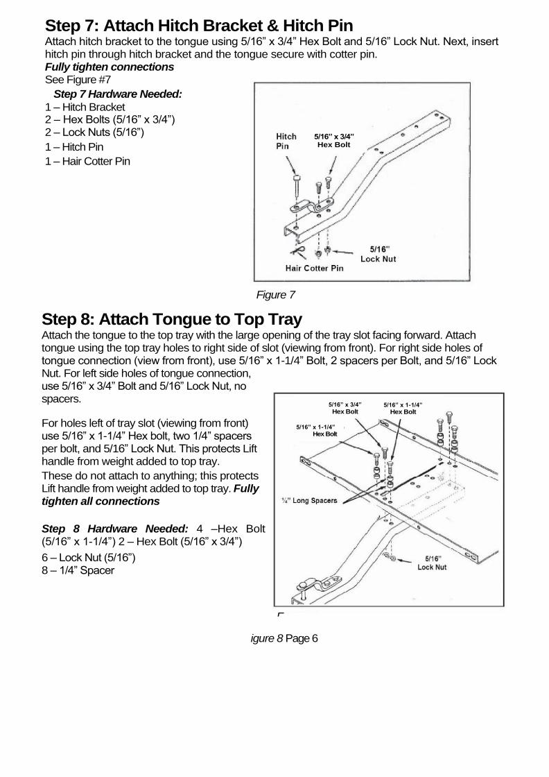
Step 7: Attach Hitch Bracket & Hitch Pin Attach hitch bracket to the tongue using 5/16” x 3/4” Hex Bolt and 5/16” Lock Nut. Next, insert hitch pin through hitch bracket and the tongue secure with cotter pin. Fully tighten connections See Figure #7
Step 7 Hardware Needed:
1 – Hitch Bracket 2 – Hex Bolts (5/16” x 3/4”) 2 – Lock Nuts (5/16”)
1 – Hitch Pin
1 – Hair Cotter Pin
Figure 7
Step 8: Attach Tongue to Top Tray Attach the tongue to the top tray with the large opening of the tray slot facing forward. Attach tongue using the top tray holes to right side of slot (viewing from front). For right side holes of tongue connection (view from front), use 5/16” x 1-1/4” Bolt, 2 spacers per Bolt, and 5/16” Lock Nut. For left side holes of tongue connection, use 5/16” x 3/4” Bolt and 5/16” Lock Nut, no spacers.
For holes left of tray slot (viewing from front) use 5/16” x 1-1/4” Hex bolt, two 1/4” spacers per bolt, and 5/16” Lock Nut. This protects Lift handle from weight added to top tray.
These do not attach to anything; this protects Lift handle from weight added to top tray. Fully tighten all connections
Step 8 Hardware Needed: 4 –Hex Bolt (5/16” x 1-1/4”) 2 – Hex Bolt (5/16” x 3/4”)
6 – Lock Nut (5/16”) 8 – 1/4” Spacer
F
igure 8 Page 6
5/16” x 3/4” Hex Bolt
5/16” x 1-1/4” Hex Bolt
5/16” x 3/4”
Hex Bolt 5/16” x 1-1/4”
Hex Bolt

Figure 10 Page 7
Step 9: Attaching Middle Brace Position Top Tray between End Plates by leaning the Top Tray into the End Plates. Temporarily attach one end plate to the top tray using 5/16” x 3/4” bolts. Swing middle brace into position and fasten to top tray using 5/16” x 1” Bolts and 5/16” Lock Nuts. Do not fully tighten until final step. Step 9 Hardware Needed: 4– Hex Bolt (5/16” x 1”) 4 – Lock Nuts (5/16”) 4 – Flat Washers (5/16”)
Step 10: Secure Upper Tray Attach both end plates to the top tray using 5/16” x 3/4” Hex Bolt, 5/16” Flat Washer, and 5/16” Lock Nut for each corner (2 connections per corner). Repeat for each corner. Do not fully tighten until final step. Step 10 Hardware Needed: 8 – Hex Bolt (5/16” x 3/4”) 8 – Lock Nuts (5/16”) 8 – Washer (5/16”)
Figure 9
5/16” x 3/4” Hex Bolt

Page 8
Step 11: Attach Lift Handle Place the lift handle through the large opening in the tray slot. Attach the lift handle to the wheel bracket using the 5/16” x 1” bolt and 5/16” nut you pre-assembled earlier in step 2, and for open hole using a 5/16” x 1” Hex Bolt, with 5/16” Lock Nut. Fully tighten connections. Step 11 Hardware Needed: 1 – Hex Bolt (5/16 x 1”) 1 – Lock Nut (5/16”)
Figure 11
5/16” x 1” Hex Bolt

Page 9
Final Step: Check Handle & Tighten Connections Carefully place the aerator upright on the wheels. Check that lift handle moves freely with-in slot; IF NEEDED, make following adjustments Lock the lift handle by moving into large offset hole in front of tray slot, then secure with locking pin. Refer to Figure #12.
For #1 in Figure #12: Adjust the Tray side to side until the lift handle moves freely from back to front For #2 in Figure #12:
Re-straighten end plates, then fully tighten all 8 corner connections making sure lift handle still moves freely.
Tighten middle brace and top tray connections from step 9 and 10
CHECK THAT ALL CONNECTIONS ARE TIGHT.
Figure #12 – Close Up Photo
BEHIND THE LIFT ARM on the top tray is a place for locking pin device. Slide locking pin through holes when aerator is in the upright position. This is a safety lock to keep the aerator from dropping down while towing and not in use. This can help prevent damage to plug knives.
Your Aerator is now fully assembled and ready for use.
MAINTENANCE: Plugger knives can be periodically sharpened with a small grinder to have continued good plugs from the soil.
Oil the axle shaft and wheel hubs as needed with spray lubricant or small amount of grease
Clean and dry the aerator before long periods of storage.
Maximum weight capacity on top tray is 120lbs.
Figure 12
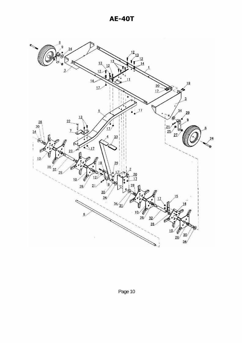
AE-40T Parts Illustration And Listing
Page 10
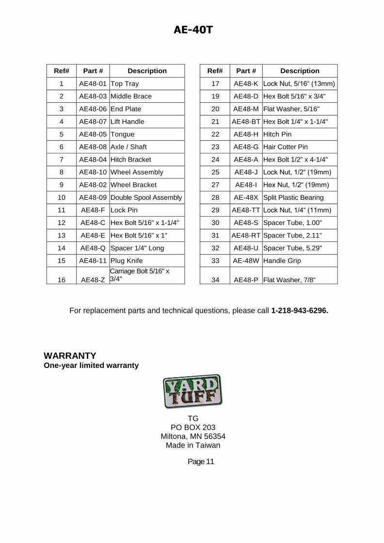
AE-40T Parts Illustration And Listing
Page 11
For replacement parts and technical questions, please call 1-218-943-6296.
WARRANTY One-year limited warranty
TG
PO BOX 203 Miltona, MN 56354
Made in Taiwan
Ref# Part # Description
1 AE48-01 Top Tray
2 AE48-03 Middle Brace
3 AE48-06 End Plate
4 AE48-07 Lift Handle
5 AE48-05 Tongue
6 AE48-08 Axle / Shaft
7 AE48-04 Hitch Bracket
8 AE48-10 Wheel Assembly
9 AE48-02 Wheel Bracket
10 AE48-09 Double Spool Assembly
11 AE48-F Lock Pin
12 AE48-C Hex Bolt 5/16" x 1-1/4"
13 AE48-E Hex Bolt 5/16" x 1"
14 AE48-Q Spacer 1/4" Long
15 AE48-11 Plug Knife
16 AE48-Z
Carriage Bolt 5/16" x 3/4"
Ref# Part # Description
17 AE48-K Lock Nut, 5/16“ (13mm)
19 AE48-D Hex Bolt 5/16" x 3/4"
20 AE48-M Flat Washer, 5/16"
21 AE48-BT Hex Bolt 1/4" x 1-1/4"
22 AE48-H Hitch Pin
23 AE48-G Hair Cotter Pin
24 AE48-A Hex Bolt 1/2" x 4-1/4"
25 AE48-J Lock Nut, 1/2“ (19mm)
27 AE48-I Hex Nut, 1/2“ (19mm)
28 AE-48X Split Plastic Bearing
29 AE48-TT Lock Nut, 1/4“ (11mm)
30 AE48-S Spacer Tube, 1.00"
31 AE48-RT Spacer Tube, 2.11"
32 AE48-U Spacer Tube, 5.29"
33 AE-48W Handle Grip
34 AE48-P Flat Washer, 7/8"