40348 a/v c and a/v c m
TRANSCRIPT

40348 AV CONTROLLER AND AV CONTROLLER MANAGER MANUAL
Table of Contents
System Requirements 1
Package Contents 1
Device Overview 2
Hardware Installation 3
Hardware Connections 4
Software Installation 5
AV Controller Manager Functions
Introduction amp Overview System Configuration Device Configuration 6
Button Settings 9
Controller Settings 16
Snapshot 18
Event Log 19
Admin 20
Adding a Device 20
Database Utility 23
Changing the active script 27
IR Learning 28
USB On-The-Go (OTG) 29
Changing the Battery 30
Changing the Buttons 30
Firmware update procedure 31
Frequently Asked QuestionsTroubleshooting 32
System Requirements
Operating System
Windowsreg Server 2003 XP Vista Sever 2008 7 8 81 and 10
Processor
400MHz Pentiumreg processor or equivalent (Minimum)
1GHz Pentiumreg processor or equivalent (Recommended)
RAM
96MB (Minimum)
256MB (Recommended)
Hard Disk
Up to 500MB of available space may be required
Display
800x600 256 Colors (Minimum)
1024x768 high color 32-bit (Recommended)
Description Replacement Part Number
C2G AV Controller Wall Plate ---
Key Plate 98073
Face Plate 40345
1 Sheet of Rubberized buttons 98078
Multiport Controller Interface Adapter (MCIA) 98071
Single IR Emitter Cable 40432
ACDC Power Adapter 98070
Mounting Hardware 98072
Always use an approved ACDC adapter that provides output power in the range of 75~12V DC 500mA
Other Available Parts Part
Numbers
Two Position Screw Terminal Block (MCIA Compo-nent)
98074
DC Power Cable 98075
Plenum-Rated DC Power Cable 98079
USB A Female to USB Mini A Male Adapter 40346
1m USB A Female to USB Mini A Male Adapter Cable 40347
1m USB A Male to 5-Pin Mini B Male Cable 27005
Package Contents
1
Device Overview
Push But-
tons
1-8
IR Learn-
ing Sensor
USB Port
RJ45
Port
Power Input Port
12V Trigger RJ45 Port
DB9 RS-232
Serial Port 1
DB9 RS-232
Serial Port 2
Stickndash On IR Emitter
35mm Mono Connector
35mm IR Emitter Port
2
Hardware Installation
Mounting the Key Plate The key plate must be mounted to the C2G AV Controller before the face plate is mounted Use the following steps to assemble and mount the key plate Arrange the buttons in the holes of the key plate Choose the buttons that will be used and tear them from the button sheet Insert the bottom tab of the key plate into the hole at the bottom of the PCB Be sure that the opening for the USB port aligns with the USB port on the PCB
Push the top of the key plate toward the PCB until the key plate locks into place
Mounting the Wall Plate Mount the C2G AV Controller to the wall following Steps 1 - 3 Step 1 Identify the desired location for mounting the junction box Step 2 Connect the Cat5E cable to the PCB wall plate controller and mount the PCB wall plate to the junction box The controller requires a minimum junction box depth of 22mm Step 3 Mount the face plate to the PCB wall plate
Multiport Controller Interface Adapter The Multiport Controller Interface Adapter (MCIA) is the central connection point for the C2G AV Controller The ports on the MCIA are as follows
55mm DC Power Port - Power input port
RJ45 - Data input port and power output port
35mm Port - IR signal output port
Screw Terminal Port - IR signal output port
DB9 Port - Serial RS232 output Port The dip switches on the MCIA alter the pinout of the DB9 Serial RS232 port There are two different settings standard and reversed See the dip switch settings to the right
Standard ldquo=ldquo - This setting configures the pinout of the DB9 port on the MCIA to match the standard Reversed ldquoXrdquo - This setting is used in situations where the Serial cable being used does not match the pinout requirements of the device being controlled ie null-modem
Connecting the Controller Step 1 Connect a Cat5E cable between the RJ45 port on the MCIA and the RJ45 port on the C2G AV Controller Step 2 Using a RS232 serial control cable (not supplied with this unit) connect the MCIArsquos DB9 port to the projectorvideo display devicersquos RS232 port (If applicable) Step 3 Connect the IR Emitter Cable to the 35mm jack on the MCIA and peel off the adhesive cover on the IR Emitter head Place the IR Emitter head on the IR eye of the device to be controlled (If applicable) Step 4 Connect the ACDC Power Adapter to an available AC outlet and then to the DC power input port on the MCIA Warning The ACDC Power Adapter should only be installed in an accessible location and in accordance with local building codes Always use an approved ACDC adapter that provides output power in the range of 75~12V DC 500mA
3
Hardware Connections
RJ45
An RJ45 port is located on both the MCIA and the back of the wall plate controller A Cat5E cable must be connected between
the MCIA and the wall plate controller to provide a link to pass power from the MCIA to the wall plate controller as well as pass
IR and Serial control signals from the wall plate controller through the MCIA to the devices that will be controlled The Cat5E ca-
ble used to connect the MCIA to the wall plate controller should be wired to the T568B pinout standard
Infrared (IR) There are two different IR ports located on the MCIA a 35 mm port and a Screw Terminal Both of these ports allow the wall plate controller to operate devices through the use of IR signals
35mm Port (IR1) - This port provides a tip-sleeve (TS) connection and accepts a standard 35mm mono connection from an IR emitter
Screw Terminal Port (IR2)- This port provides a bare wire connection from an IR emitter and will accept a minimum wire
gauge of 24AWG and a maximum wire gauge of 14AWG This port is ideal for situations where the IR emitter must be ex-
tended The left opening is the positive and the right opening is the negative portion of the IR signal
Serial RS232DB9 Port This port allows the controller to operate devices through the use of Serial RS232 commands The dip switches on the MCIA alter the pinout of the DB9 Serial RS232 port There are two different settings straight and crossed (null-modem)
55mm DC Power Port This port on the MCIA accepts a 9V 500mA DC power input from the ACDC power adapter or other DC power source and pro-vides power to the wall plate controller Always use an approved ACDC adapter that provides output power in the range of 75~12V DC 500mA 4
Software Installation
Note Do not connect the C2G AV controller to the host PC until the software program has been installed Step 1 Insert the software installation CD into the computers CD drive If AutoPlay is enabled then the software installation process will begin immediately If AutoPlay is not enabled on the computer then open Windows Explorer navigate to the contents of the CD drive and then double-click on the Setupexe file to install the software
Step 2 Once the installation process has started through AutoPlay or the Setupexe file the computer will prepare to install the software
Step 3 After the computer has prepared the installation the AV Controller Manager software welcome screen will appear Click the Next gt button to continue
Step 4 Select the installation folder where the software will be installed The default installation location CProgram Files (x86)AV Controller Manager will be auto-populated in the folder text box and using that location is recommended Click on the Next gt button to continue
Step 5 The installer will indicate that it is ready to install the software on the computer Click the Next gt button to continue
Step 6 After a brief installation process the installer will indicate that the AV Control Manager has been successfully installed Click the Close button to exit the installer
5
Introduction The AV Controller Manager is the graphical user interface (GUI) software that allows a user to configure and program the C2G AV Controller The GUI is pre-loaded with serial RS-232 commands for many popular projectors allowing for faster installation However the GUI provides the ability to add devices that are not pre-loaded into the library To begin programming connect the controller to an available USB port on the computer and then start the GUI by simply double clicking the AV Controller Manager icon on the desktop or in the Start menu
AV Controller Manager Functions
The System Configuration screen is the first step in the programming process
and is used to ensure that the controller is being properly recognized by the
GUI To perform this check click on the System Configuration tab and then
click on the Read Controller Version button If the controller is properly
recognized then the System Configuration chart will be populated with the
controllers firmware hardware and software version numbers If the
information is not populated then please see the Troubleshooting amp FAQs
section for possible solutions
Device Configuration
The Device Configuration screen allows devices that are programmed into the
GUI to be selected so that they may be used for button programming Up to six
devices may be added simultaneously Use the dropdown boxes within the
Device Information field to select the Device Type ManufacturerBrand Model
Number and Control Command type of each device that is to be configured
Once all fields have been selected click on the Save button to add the device to
the table on the right side of the GUI window Repeat this process for each
device that will be added for programming Once all devices have been added
continue to the Button Settings tab
If a Device Type ManufacturerBrand or Model Number is not listed in the drop
downs of the Device Information field then it must be added through the Admin
tab Please see the Admin section for specific instructions on adding a device
For 12V trigger device configuration use the following settings
Device Type - Controller
ManufacturerBrand - C2G
Model Number - MCIA2
Note If a device will be setup for both serial and IR Control Command Types
then it must be added to the device table twice Enter the device once with a
Control Command Type of serial and once with a Control Command Type of
IR
To remove a device from the table click on the red button within the Delete
column
AV Controller Manager
6
Device Configuration Example
Step 1 Select the Device Type from the dropdown within the Device Information field
Step 2 Select the ManufacturerBrand from the dropdown within the Device Information field
Step 3 Select the Model Number from the dropdown within the Device
Information field If applicable select the Control Command Type from the
Device Information field
Step 4 Set the Baud rate to the manufactured determined increment The
Baud rate is often found in device manual or directly from the manufacturer
Step 5 Set the port number based on which port the selected device has
been plugged into on the MCIA2 box
Note The Control Command field will only need to be selected if the device has both serial and IR commands stored in the GUI library If only serial or IR are entered into the GUI library then this field will auto-populate
7
Step 6 Click on the Save button to store the device information in the Device table Repeat these steps for all devices in the system that will be controlled Up to six devices may be programmed simultaneously
Note Click on the red button within the Delete column to remove a device from the table
8
Button Settings
Clickable Area Function Related Area
Clicking on the numbered buttons in this area selects the button that will be
programmed The button number that is currently being programmed will be
displayed in the Button column in the programming table
Timed Events may only be used on one of the virtual buttons Clicking on one of
the virtual buttons 9 - 12 automatically activates the Timed Events
configuration window
The Timed Event configuration window opens to Daily programming by default
Daily programming provides the ability to program an event which will occur on
specific days of the week at specific times The Save Settings button saves the
day and time configuration The Clear Settings button will clear the day and time
configuration
Click on the Repeat button to access the Repeat configuration window Repeat
programming provides the ability to program the duration between event
occurrences This means that the events will occur whenever the set duration
has elapsed The Save Settings button saves the duration time configuration
The Clear Settings button will clear the duration time configuration
Click on the top of the Button Press column highlighted in red to activate the
Button Press Option configuration window This option is set to Single by
default The Single configuration allows one command to be programmed to the
button While in Single each press of the button will execute the single
command that is programmed on the button
Click on the Sequential button to enable the programming of up to four
commands per button Once the controller is programmed with the Sequential
Button Press Option each press of the button will perform the next command in
the command stack Once the last command in the command stack has been
performed the next press of the button will perform the first command in the
command stack
Click on the Fire All button which will enable the programming of up to four
commands per button Once the controller is programmed with the Fire All
Button Press Option each press of the button will perform all of the commands
in the command stack with a delay between each command Use the Program
Delay dropdown to select the amount of delay between each of the command
performed
The Button Settings screen allows the buttons to be configured with the functions that will control the devices in the AV system The screen shows the standard button layout on the wall plate controller 1 - 8 the four virtual buttons 9 - 12 as well as the 36 button functions Please note that the virtual buttons cannot be accessed through the buttons on the wall plate controller and are only used for timed events
The following table illustrates the various clickable areas within the Button
Settings screen and explains the function of each area It is
recommended that this section is read before programming the buttons
9
Button Settings
Clickable Area Function Related Area
When programming button 8 click on the Button Press column to activate the
Button Press Option configuration window and then click on the Keypad Lock
button which will program button 8 as the lock button Once the controller is
programmed with the Keypad Lock on button 8 pressing button 8 will lock out
the keypad until the selected pin is entered This option also allows the user to
select the duration of the inactivity timer Once this time is selected the
controller will automatically lock if it has not been used for the selected period of
time Use the text box next to PIN to enter the PIN code that will be required
to unlock the controller The pin numbers will relate to the button numbers on the
controller so the pin must use numbers between 1 and 8 and must be four digits
in length Use the dropdown next to Time to Lock to select the time period in
seconds of the inactivity timer When Keypad Lock has been selected for button
8 the button 8 within the GUI will show a lock icon
Click on the top of the Repeat Command column highlighted in red to activate
the Repeat Command configuration window which is set to off by default When
the Repeat Command Option is off pressing and holding the button on the
controller will have no affect on the number of times the command is executed
Click the Repeat On button to activate the Repeat Command Option When the
Repeat Command Option is enabled pressing and holding the button on the
controller will cause the command to be repeatedly executed until the button is
released The most common application for using this function is when
programming volume controls
Use the dropdown in the Device column to select which device will be controlled
by the command
Use the dropdown in the Function column to select which command will be
programmed on the button
Clicking the Read Button button downloads and displays the configuration
information of the active script on the controller The AV Controller must be
connected to a USB port on the computer for this button to function properly
Clicking the Save Button button stores the configuration information for the
button that is currently being programmed within the GUI Each button must be
saved before configuring a different button Switching to another button without
clicking the Save Button will cause the configuration information to be lost
Clicking the Clear Button Settings button deletes the configuration information
for the button that is currently being programmed
Clicking the Play Button Commands button executes the commands that have
been configured for the current button to test for functionality
Clicking the Save Script button saves the configuration information from all
buttons into a format that may be uploaded to the controller
Clicking the Clear All Buttons button deletes the configuration in the GUI from all
buttons
10
Button Settings Example
Accessing the Button Settings Tab
Click within the Button Settings tab under the AV Controller Manager title bar to program and configure the specific functions of each button
Button Selection
Click on the numbered buttons within this area to select the button which will be programmed The button that is currently being programmed will be displayed in the Button column of the Programming table
Timed Events
Timed Events may only be used on one of the virtual buttons Clicking on one of the virtual buttons 9 - 12 automatically activates the Timed Events configuration window
Daily Timed Event
The Timed Event configuration window opens to Daily programming by default Daily programming provides the ability to program an event that will occur on a specific day of the week at a specific time To program a timed event hold down the CTRL key on the keyboard and use the mouse to click on each day that the event should occur and then use the dropdown boxes to select the time of day that the event will occur Click on the Save Settings button to store the day and time configuration The Clear Setting button will clear the day and
11
Button Settings Example
Button Press
Click on the top of the Button Press column in the Programming Table to open the Button Press Option configuration panel This configuration panel controls how the controller sends stacked commands up to 4 per button to the devices Three options are available through the Button Press Option configuration panel Single Sequential Fire All Single - This is the default option and is used when only a single command has been programmed to the button This option will send that single command each time the button is pressed
Button Press - Sequential
This option is used to program more than one command to the button and will send the next command in the stack each time the button is pressed Once the last command in the stack has been performed the next button press will perform the first command in the stack
Button Press - Fire All
This option is used to program more than one command to the button and will perform all commands in the stack each time the button is pressed When selecting this option a program delay must be selected using the dropdown in the Button Press Option configuration panel The program delay allows an interval between 1 and 255 seconds to be set between the firing of the commands in the stack
Button Press - Keypad Lock
This option is used to program button 8 as the Keypad Lock When selecting this option a PIN number and Time to Lock duration must be selected using the text box and dropdown in the Button Press Option configuration panel The PIN number is used to unlock the keypad and the Time to Lock time period is a timer that will automatically lock the controller after a period of inactivity
12
Button Settings Example
Repeat Command
Click on the top of the Repeat Command column in the Programming Table to open the Repeat Command Option configuration panel The Repeat Command option is set to Off by default When the Repeat Command Option is Off pressing and holding the button on the controller will have no affect on the number of times the command is performed
Repeat Command
Click the Repeat On button to activate the Repeat Command Option When the Repeat Command Option is on pressing and holding the button on the wall plate controller will cause the command to be repeatedly executed until the button is released The most common application for this option is when programming Volume controls
Device
The Device column in the Programming Table is used to select the device that will be controlled Use the dropdown in the column to select the device When the device is selected the Mode column will automatically populate with the Control Command Type that was selected on the Device Configuration screen
Function
The Function column in the Programming Table is used to select the command that will be used to control the device selected in the Device Column Use the dropdown in the column to select the command
13
Button Settings Example
Read Button
This button is used to read the configuration information that is currently stored in the active script on the wall plate controller Note The wall plate controller must be connected to a USB port on the computer for this button to function
Save Button
This button is used to store the configuration information for the button that is currently being programmed in the GUI Each button must be saved before configuring a different button Note If a button is not saved before configuring a different button then the configuration information will be lost
Clear Button Settings
This button is used to delete the configuration information for the button that is currently being programmed in the GUI
Play Button Commands
This button is used to test the configuration information programmed to the button Note The button configuration information must be saved the wall plate controller must be connected to a USB port on the computer and the MCIA must be connected to the device through IR or serial for this button to function
14
Button Settings Example
Save Script
This button is used to save the configuration information from all of the buttons into a file format that may be uploaded to the wall plate controller Note The default location for saved script files is CProgram Files (x86)AV Controller Manager It is recommended that script files be saved in this default location unless the script will be saved to a USB thumb drive
Clear All Buttons
This button is used to delete the configuration information from all buttons
15
Controller Settings
Accessing Controller Settings
Click within the Controller Settings tab under the AV Controller Manager title bar to upload and download scripts as well as change various controller settings
Install Configuration From File
This button is used to load script files stored in a location on the computer other than the default location CProgram Files (x86)AV Controller Manager Files loaded into the GUI using this button will appear in the Available Configuration Files window Note Script files that are saved in the default location CProgram Files (x86)AV Controller Manager will automatically appear in the Available Configuration Files window
Active Configuration File
To upload a script file to the wall plate controller the script file must be moved from the Available Configuration Files window to the Active Configuration File window To move a file between the windows click on the file to be moved and then click on the arrow button between the two windows to move the file Note Only one file may be moved to the Active Configuration File window and uploaded to the controller at a time
16
Controller Settings
Upload Script
This button is used to upload the script in the Active Configuration File window to the wall plate controller Use the following steps to upload a script Step 1 Move one script from the Available Configuration Files window to the Active Configuration File window Step 2 Click on the Upload Script button Step 3 Use the dropdown in the popup window to select an available Scenario number between 1 and 9 and then click on the OK button Note The wall plate controller must be connected to a USB port on the computer Only one file may be uploaded to the wall plate controller at a time This process must be repeated for each script uploaded to the wall plate controller
Clear Configuration
This button is used to remove a script from the Active Configuration File window This will allow other scripts to be uploaded to the wall plate controller
Set Controller Date Time
This button is used to read and adjust the wall plate controllers date and time settings Click on the Apply button to save any changes that are made before clicking on the OK button to exit Click on the Set to PC Time button to set the wall plate controller to match the computers date and time settings Note The wall plate controller must be connected to a USB port on the computer for this button to function
Tone Settings
This button is used to turn the wall plate controllers tone on or off The wall plate controllers tone is on by default and the controller will produce an audible tone with button presses To turn off this setting click on the Tone Settings - Off button Note The wall plate controller must be connected to a USB port on the computer for this button to function
17
Controller Settings
Factory Reset
This button is used to restore the wall plate controller to the factory settings and will erase the memory on the controller Warning Any configuration information that is stored on the wall plate controller will be erased and will be unrecoverable Note The wall plate controller must be connected to a USB port on the computer for this button to function
Password Settings
This button is not active in this version of software
Snapshot
Accessing Snapshot
This screen shows the current configuration for buttons 1 - 8 within the GUI Click on the Snapshot tab under the AV Controller Manager title bar to access this information
Snapshot - Virtual Buttons
To view the current configuration information of the virtual buttons 9 - 12 within the GUI click on the virtual buttons link at the bottom of the Snapshot tab Note This link will not be active unless information has been saved to the virtual buttons
18
Event Log
Accessing Event Log
This screen provides information on changes that have been made to the wall plate controller Click on the Event Log tab under the AV Controller Manager title bar to access this information Note The wall plate controller must be connected to a USB port on the computer for this button to function
Event Log - Export Log
The Export Log button save the Event Log information to a file on the computer Clicking the button opens a popup window to chose the save location and file name Note The wall plate controller must be connected to a USB port on the computer for this button to function
Event Log - Clear Log
The Clear Log button will erase the Event Log information from the controller Note The wall plate controller must be connected to a USB port on the computer for this button to function
19
Admin
Accessing Admin
The Admin tab provides the ability to add devices and make adjustments to the control command database Click on the Admin tab under the AV Controller Manager title bar to access this information
Adding a Device
Device Type
Admin will open to the Device Type screen by default This screen allows different types of devices ie Blu-ray DVD etc to be added to the control command database To add a device type type the name of the device type into the Device Type Name text box click on the Submit button and then click on the OK button in the popup window To remove a device type click on the device type within the View Delete Device field click on the Delete button at the bottom of the filed and then click on the OK button in the popup window
Brand
Use the dropdown at the top of the Admin screen to switch to the brand screen The brand screen allows different brands to be added to the control command database
20
Adding a Device
Brand - Adding a brand
To add a brand type the brand name into the Brand Name text box click on the Submit button and then click on the OK button in the popup window To remove a brand click on the brand within the View Delete Device field click on the Delete button at the bottom of the filed and then click on the OK button in the popup window
Model
Use the dropdown at the top of the Admin screen to switch to the model screen The model screen allows different model numbers to be added to the control command database
Model - Adding a model number
To add a model number select the device type using the Select Device dropdown select the brand name using the Select Brand dropdown type the model number into the Model Name text box click on the Submit button and then click on the OK button in the popup window To remove a model click on the model within the View Delete Device field click on the Delete button at the bottom of the filed and then click on the OK button in the popup window
Device Details
Use the dropdown at the top of the Admin screen to switch to the device details screen The device details screen allows an assignment of IR or serial control for the commands that will be entered into the control command database
21
Adding a Device
Device Details - Assigning device details
To assign device details select the device type using the Device Type dropdown select the brand name using the Brand dropdown select the model number using the Model dropdown click on the radio button for IR or Serial click on the Submit button and then click on the OK button in the popup window To assign device details to a different device click on the Reset button and then repeat the steps described above
Device Functions
Use the dropdown at the top of the Admin screen to switch to the device func-tions screen The device functions screen allows the control commands for the device to be entered into the control command database
22
Adding a Device
This dropdown will auto-populate with the control type entered on the Device Details screen unless the device has been entered twice as IR and serial If both control types have been entered on the Device Details screen then select the control type for the functions that will be entered into the control command database The command must be learned by the wall plate controller within 60 seconds of clicking lt Learn IR gt If the command is not learned in that time frame then the software will present a time out message and the process must be repeated When the command is successfully learned the controller will beep and the command string will appear in the command string text box If the button on the IR remote is pressed for too long of a duration during the learning step the IR command string may repeat multiple time If the code is duplicated multiple times it will cause the command to fail To correct a command failure please delete the previous command and try the learning phase again
Device Functions - Adding device functions
To assign device functions select the device type using the Device Type dropdown select the brand name using the Brand dropdown select the model number using the Model dropdown select the control type using the Control Type dropdown and then use the Function Name dropdown to select lt Add New Function gt or if IR lt Learn IR gt Serial Commands Selecting lt Add New Function gt is required for entering serial commands After selecting lt Add New Function gt enter the name of the function ie Power On Power Off etc into the Function Name text box enter the command string into the Command String text box click on Submit button and then click on the OK button in the popup window Infrared Commands IR commands may be manually entered by selecting lt Add New Function gt After selecting lt Add New Function gt type the name of the function ie Power On Power Off etc into the Function Name text box enter the command string into the Command String text box click on Submit button and then click on the OK button in the popup window IR commands may also be learned through the wall plate controllers IR receiver by selecting lt Learn IR gt The wall plate controller must be connected to a USB port on the computer for this function to work After clicking on lt Learn IR gt point the devices remote at the IR window on the wall plate controller press the button on the remote for the function that will be learned for a very short duration type the name of the function ie Power On Power Off etc into the Function Name text box click on Submit button and then click on the OK button in the popup window To assign device functions to a different device click on the Reset button and then repeat the steps described above
Database Utility
Accessing Database Utility
The Database Utility screen allows for additions to and storage of the control command database using Microsoft
reg Access database files Use the dropdown
at the top of the Admin screen to switch to the Database Utility screen
23
Database Utility
Accessing the Database Utility
The Database Utility screen allows for additions to and storage of the control command database using Microsoft
reg Access database files Use the dropdown
at the top of the Admin screen to switch to the Database Utility screen
Database Utility - Export
The export button compresses and stores the database information Click on the Export button select a location on the computer for storage through the popup window and then click on the Save button to save the file and close the popup window
Database Utility - Import
The import button allows a Microsoftreg Access file to be uploaded to the control
command database See the file format below for the required fields To import a file click on the Import button select the file through the popup window and then click on the Open button to import the file and close the popup window Note Importing a file will add information to the database and will only replace information in the database that is duplicate
Database Utility - Backup
The Backup button stores the database information to a location on the computer Click on the Backup button select a location on the computer for storage through the popup window and then click on the Save button to save the file and close the popup window
24
Database Utility
Import Excel Files
The Import Excel Files screen allows for additions to the control command database using Microsoft
reg Excel files Use the dropdown at the top of the
Admin screen to switch to the Import Excel Files screen
Import Excel Files - Start
The Start button allows a Microsoftreg Excel file to be uploaded to the control
command database See the file format below for the required fields To import a file click on the Start button select the folder that contains the Excel file through the popup window and then click on the OK button to import the file and close the popup window Note Importing a file will add information to the database and will only replace information in the database that is duplicate
Import Excel Files - Clear Data Base
The Clear Data Base button compresses the database and remove the data This allows for a smaller database with fewer options which may streamline programming To clear the database click on the Clear Data Base button and then click OK on the popup window
25
Database Utility
Note A sample file comes with the software The sample file can be modified to create a custom device type data base The sample file is located under CProgramFiles (x86)AV Controller Manager4200W-Serialxlsx When saving the new file ensure that the file name ends with -serialxlsx 1 Device Type should describe the device that is being entered ie Projector Blu-ray Player etc 2 Multiple model numbers should be listed in different cells of column C Adding multiple model number in the same cell will
create an error when importing the data 3 Controller Type can only be Serial or IR 4 List Baud Rate without abbreviations Example 192Kbps should be listed as 19200 5 Columns F to I should only contain one character per cell If the requirement is =None use N 6 Column K will be a combination of upper and lower case letters using the description outlined in the user manual for the
device 7 Column L is for ASCII code only and will not be imported to the database 8 Columns M N and O is for the main code string in Hexadecimal M is used for the Start bit N is used for the main
code and O is for the EndReturn bit
Required fields for Microsoftreg Access and Microsoft
reg Excel files
26
The C2G AV Controller is able to hold up to nine different scripts programmed through the GUI and one script that is reserved for the IR learning function Use the following steps to switch the active script Step 1 Put the controller into administrator mode by connecting a USB Mini A adapter or cable to the USB port on the front of the wall plate controller When in administrator mode all of the buttons will be illuminated blue with the exception of button number 8 which will be illuminated green Step 2 Press and release button number 2 and then enter the code for the desired script (refer to the chart below for script codes) After pressing button number 2 the script code must be entered within 5 seconds or an error will occur indicated by a triple beep and button number 8 which will be illuminated red If an error occurs then the controller will remain in error mode for 15 seconds and then will return to administrator mode and the script change may be attempted again If the script code is entered correctly then the controller will beep button 8 will blink green and the button corresponding to the script will blink twice to confirm the selection After several seconds all keys will illuminate in sequence and the controller will be reset This confirms that the new script is loaded and the controller is ready to use Note Buttons 1 and 8 will blink when script 9 is selected and buttons 2 and 8 will blink twice when script 10 is selected
Script Script Code
Script 1 1 - 1 - 1
Script 2 2 - 2 - 2
Script 3 3 - 3 - 3
Script 4 4 - 4 - 4
Script 5 5 - 5 - 5
Script 6 6 - 6 - 6
Script 7 7 - 7 - 7
Script 8 8 - 8 - 8
Script 9 1 - 1 - 2
Script 10 (IR Learning)
1 - 1 - 3
Changing the Active Script
27
The C2G AV Controller is capable of learning IR commands from a devices remote control through the front of the wall plate Use the following steps to learn IR Commands Step 1 Put the controller into administrator mode by connecting a USB Mini A adapter or cable to the USB port on the front of the wall plate controller When in administrator mode all of the buttons will be illuminated blue with the exception of button number 8 which will be illuminated green Step 2 Press and release button number 4 to enter IR learning mode After pressing button number 4 all buttons will dim and then button 8 will illuminate green when the controller is ready to proceed Step 3 Press and release the button that is to be programmed within 10 seconds of button 8 illuminating green The button that was pressed will be illuminated blue as well as the top button 1 or 2 of the opposite column of buttons This indicates that the button will be programmed with one command Press and release the button that is being programmed up to three additional times to increase the number of commands that will be programmed to that button Step 4 After the proper number of commands have been selected wait five seconds and then the top button 1 or 2 in the column opposite of the button being programmed will begin blinking indicating that the controller is ready to learn the first command Step 5 Point the devices remote control at the IR window on the wall plate controller and press the button on the remote control for the command that will be learned When the command is learned the controller will beep once and the top button 1 or 2 in the column opposite of the button being programmed will stop blinking indicating that the code has been successfully learned The next button down in the column opposite of the button being programmed will begin blinking indicating that the controller is ready to learn the next command Repeat this process until the last command has been learned Step 6 Once the last command has been learned all buttons will dim except for the button that is being programmed which will being blinking and continue to blink for eight seconds During this time the blinking button may be pressed and held for five seconds to set the button press option
If a single command is learnedhellip
the default button press option setting is Single In this mode each press of the button will fire the command
and the blinking button is pressed and held for five seconds then the button press option will be set to Repeat In this mode holding down the button will repeatedly fire the command until the button is released This is typically used for volume controls
If multiple commands are learnedhellip
the default button press option setting is Sequential In this mode each press of the button will fire the next command in the stack After the last command has been fired the next button press will perform the first command in the stack
and the blinking button is pressed and held for five seconds then the button press option will be set to Fire-All In this mode each press of the button will fire all commands in the stack
Once eight seconds have elapsed or the button being programmed has been pressed and held the controller will beep and all buttons will be illuminated blue with the exception of button 8 which will be illuminated green Step 7 Repeat steps 1 through 6 for each button that is to be programmed through IR learning Step 8 Once all buttons have been programmed switch to script 10 where the IR learning information is stored Use the following steps to select script 10
Insert the mini-A USB adapter into the USB port on the front of the controller The controller will enter Admin mode indicated by button 8 being illuminated green
Push button 2 to enter script selection mode
Within 5 seconds of pushing button 2 push the sequence 1 - 1 - 3 to select script 10
If the script code is entered correctly then the controller will beep button 8 will blink green and then button 8 and 2 will blink twice to confirm the selection
Remove the Mini-A USB adapter to resume normal operation using script 10 See the Changing scripts from the controller keypad section for specific instructions on changing scripts If the button that is to be programmed is not pressed then the controller will present an error The controller will beep twice button 8 will blink red and then the controller will return to administrator mode After an error these steps will have to be repeated to enter IR learning mode and learn IR commands
IR Learning Direct To The Face Plate
28
The C2G AV Controller features USB On-The-Go which allows scripts to be uploaded or downloaded from a USB thumb drive Uploading a script to the controller Note The script that is uploaded from a USB thumb drive to the controller will overwrite the active script Use the instructions in the Changing scripts from the controller keypad section to select an empty script or a script that may be overwritten before uploading from a USB thumbdrive Note When saving a script file to the USB thumb drive it must be saved within a specific folder named script and with a specific name scenarioxml If the file is not saved in the required format then it will not be possible to upload the file The following path must be used for saving the file
scriptscenarioxml
If the script is downloaded of another C2G AV Controller then it will automatically be placed in this path with these names Use the following steps to upload a script to the controller Step 1 Save a script file to a USB thumb drive from a computer to the path scriptscenarioxml or download a script from another C2G AV Controller Step 2 Connect the USB thumb drive to the USB A female port of a USB A female to USB Mini A male adapter or adapter cable and then connect the adapter or adapter cable to the USB port on the front of the wall plate controller Once connected the controller will enter Admin mode indicated by button 8 which will be illuminated green Step 3 Press and release button 1 to begin the upload process After a few seconds the buttons will repeatedly light in the following sequence 7 5 3 1 which will indicate uploading The controller will beep and the buttons will stop blinking to indicate that the upload is complete Step 4 Disconnect the adapter or adapter cable from the controller to return to normal operation Downloading a script from the controller Note The controller will download the active script only Use the following steps to download a script from the controller Use the instructions in the Changing scripts from the controller keypad section to select the script that will be downloaded Step 1 Connect the USB thumb drive to the USB A female port of a USB A female to USB Mini A male adapter or adapter cable and then connect the adapter or adapter cable to the USB port on the front of the wall plate controller Once connected the controller will enter Admin mode indicated by button 8 which will be illuminated green Step 2 Press and release button 3 to begin the download process After a few seconds the buttons will repeatedly light in the following sequence 1 3 5 7 which will indicate downloading The controller will beep and the buttons will stop blinking to indicate that the download is complete Step 3 Disconnect the adapter or the adapter cable from the controller to return to normal operation
29
The C2G AV Controller contains a CR1225 battery that support the real-time clock operation for timed events The battery is located between the main PCB of the wall plate controller and the daughter board PCB at the top of the wall plate Use the following steps to replace the battery Warning Ensure that the controller is disconnected from power before replacing the battery Failure to do so may result in damage to the controller Step 1 Remove the wall plate from its mounting location and disconnect the Cat5E cable Step 2 Locate and remove the battery The battery is located between the main PCB of the wall plate controller and the daughter board PCB at the top of the wall plate Note To avoid damage to the controller use a small non-conductive object to remove the battery Step 3 Insert a new battery size CR1225 into the wall plate controller The positive side of the battery should face the main PCB and the front of the wall plate controller Step 4 Reconnect the Cat5E cable and mount the wall plate Caution There is a risk of explosion if the battery is replaced by an incorrect type Dispose of old batteries in accordance with local laws
Changing the Battery
Use the following instructions to change the buttons on the wall plate controller Step 1 Remove the wall plate from its mounting location and disconnect the Cat5E cable Step 2 From the back of the wall plate controller push down on the key plate retaining tab and then toward the front of the wall plate Step 3 Once the top retaining tab is loose carefully remove the key plate from the wall plate controller Step 4 Choose the buttons that will be used and tear them from the button sheet Step 5 Arrange the buttons in the holes of the key plate Step 6 Insert the bottom tab of the key plate into the hole at the bottom of the PCB Be sure that the opening for the USB port aligns with the USB port on the PCB Step 7 Push the top of the key plate toward the PCB until the key plate locks into place Step 8 Reconnect the Cat5E cable and mount the wall plate
Changing the buttons
30
Updating the firmware of the AV Controller may be required occasionally Use the following steps to update the firmware Note Copy the entire Firmware folder from CProgram Files (x86)AV Controller Manager onto a USB thumb drive Make sure no other file folders have firmware in the file name on the thumb drive Use the following steps to update the firmware of the controller Step 1 Save the firmware folder to a USB thumb drive from a computer with the AV Controller software Step 2 Connect the USB thumb drive to the USB A female port of a USB A female to USB Mini A male adapter or adapter cable and then connect the adapter or adapter cable to the USB port on the front of the wall plate controller Once connected the controller will enter Admin mode indicated by button 8 which will be illuminated green Step 3 Press and release button 7 to begin the update process After a few seconds the buttons will repeatedly light in the following sequence 7 5 3 1 which will indicate updating The controller will beep and the buttons will stop blinking to indicate that the update is complete Step 4 Disconnect the adapter or adapter cable from the controller to return to normal operation
Firmware Update Procedure
31
1 The serial codes that I entered are not working What can I do 2 The make and model of my serial or IR device is not listed how can I add it 3 Where can I get a replacement USB mini-A adapter in order to access admin mode 4 How can I change the active script that I am using 5 I am receiving an error when trying to upload a script from a USB thumbdrive What is the problem 6 The controller is not lighting up blue What is the problem 7 Where can I get a serial cable to go from the MCIA to my projector 8 How can I extend the IR emitter cable longer than the 9 foot cable provided 9 How do I locate the serial codes for my device 10 How do I load the same script onto other controllers 11 The controller is not being recognized by the software What can I do 12 I am receiving an error when uploading firmware from a USB thumbdrive What is the problem 13 I am receiving an error when downloading a script to a USB thumbdrive What is the problem 14 I am receiving an error when attempting to learn IR commands through the face plate What is the problem 1 The serial codes that I entered are not working What can I do
Please make sure that the serial codes are entered in Hexadecimal format and not ASCII If the serial codes are provided in ASCII format then they will need to be converted to Hexadecimal
Verify that the baud rate is set correctly for the model of projector
Make certain the serial cable being used is the correct pinout for the projector
If the cable is a straight through serial cable and the projector requires null modem then use the dip switches on the MCIA adapter to reverse the pinout of the cable
2 The make and model of my serial or IR device is not listed how can I add it
If a device is not listed in the pre-configured devices then it must be manually addedPlease click on the admin tab login and then follow the instructions on Adding a DeviceEach IR or serial command that will be used for that device must be added through the Adding a Device screen
3 Where can I get a replacement USB mini-A adapter in order to access admin mode
Please contact us at 800-506-9607 in order to obtain a replacement USB mini-A adapter Two options are available
40346 - USB A Female to USB Mini-A Male Adapter
40347 - 1m USB A Female to USB Mini-A Male Adapter Cable 4 How can I change the active script that I am using
Please refer to the Changing scripts from the controller keypad section
5 I am receiving an error when trying to upload a script from a USB drive What is the problem There may be a few issues that would cause this problem
Ensure that the script file is saved on the USB thumbdrive in the proper folder and that it is named properly The file must be saved to the following folder with the following name scriptscenarioxml
Ensure that the USB OTG upload procedures are followed See the USB OTG section for upload procedures
Ensure that the USB thumbdrive is known good and working Test with a different USB thumbdrive if available
6 The controller is not lighting up blue What is the problem
Make sure the controller is connected to the MCIA adapter with a known good Cat5E cable Verify that the Cat5E cable is good by testing that cable with a continuity tester or a different Cat5E cable
Make sure the MCIA adapter is connected to power The power cable should be plugged into the MCIA on one end and then connected to a power outlet or the C2G Audio Amplifier
Test an additional wall plate controller MCIA adapter or power adaptercable it in the same configuration (If available)
7 Where can I get a serial cable to go from the MCIA to my projector
That depends upon the serial connector on the projector If the serial connection on the projector is a DB9 port then we offer a wide selection of cables that may be used If the serial connection on the projector is a different connector than a DB9 then contact us at 800-506-9607 to see if we carry or if we can make the cable for the projector
FAQTroubleshooting
32
8 How can I extend the IR emitter cable longer than the 9 foot cable provided There are 2 ways to extend the IR emitters 1 A 35mm mono extension cable may be used to extend the IR emitter up to 25ft 2 The screw terminal block that connects to the IR2 port on the side of the MCIA adapter may be used to extend the
IR emitter up to 50ft This extension requires a cable that has at least 2 conductors (ie a Cat5E cable) and a 2-conductor 35mm keystone jack similar to our item 37035 Use the following steps to extend the IR emitter from the screw terminal
Remove the green screw terminal block connector from the controllers packaging
Select a bulk cable that has a least 2 conductors with at minimum wire gauge of 24AWG ie Cat5E cable at the
appropriate length for the IR emitter extension up to 50ft
Insert and secure the conductors into the two opening of the screw terminal block
Secure the other end of the conductors into the back of the keystone jack 37035
To terminate to the keystone jack push down on the orange tabs and insert the wires The left side
(screw facing up) conductor of the screw terminal block connects to the positive (+) position on the keystone and the right side (screw facing up) conductor of the screw terminal block connects to the Negative (-) position on the keystone
Connect the IR emitter cable to the 35mm female port on the keystone jack remove the adhesive cover
from the IR emitter head and then stick the IR emitter heard on the IR receive of the device to be controlled
9 How do I locate the serial codes for my device
This can be commonly found in the manual of the device If this information is not included in the manual then contact the manufacturer of the device to obtain the serial codes
10 How do I load the same script onto other controllers
Once the script has been created in the Button Setting section of the software it can be saved onto a USB thumbdrive and
uploaded to other controllers
It is also possible to download the active script from one controller and then upload it to another controller Please see the
upload and download steps in the USB OTG section for specific instructions on this process
11 The controller is not being recognized by the software What can I do
Verify that the USB cable used to connect the controller to the computers USB port is known good Test with an alternate
USB cable if available
Verify that the controller is connected to power through the MCIA adapter All of the buttons on the controller should be
illuminated blue If the buttons are not illuminated blue then see question 9 for possible solutions
If the software was started before the controller was connected to the computer then the controller will not be recognized
To correct this issue disconnect the controller shut down the software reconnect the controller and then start the software
Verify that the controller is being recognized by the computer While the controller is connected to the computer open
Windows Device Manger The AV Controller should be listed the category of libusb-win32 devices as Audio Video Controller
12 I am receiving an error when uploading firmware from a USB thumbdrive What is the problem
There may be a few issues that would cause this problem
Ensure that the firmware file is saved on the USB thumbdrive in the proper folder and that it is named properly
The file must be saved to the following folder with the following name firmwarefirmwaredfu
Ensure that the firmware update procedures are followed See the Firmware Update section for the update
process
Ensure that the USB thumbdrive is known good and working Test with a different USB thumbdrive if available
13 I am receiving an error when downloading a script to a USB thumbdrive What is the problem
There may be a couple of issues that would cause this problem
Ensure that the script download procedures are followed See the USB OTG section for specific instructions on
this process
Ensure that the USB thumbdrive is known good and working Test with a different USB thumbdrive if available
14 I am receiving an error when attempting to learn IR commands through the face plate What is the problem
There may be a few issues that would cause this problem
Ensure that the procedures in the IR learning through the face plate are followed See the IR Learning through the
face plate for specific instructions on this process
When IR Learning mode has been initiated the key that will be programmed must be pressed within 10 seconds
If this key is not pressed then the controller will present an error
Once the controller has indicated that it is ready to learn an IR command the command must be sent within 20
seconds If the command is not sent then the controller will present an error
FAQTroubleshooting
33

Button Settings
Clickable Area Function Related Area
When programming button 8 click on the Button Press column to activate the
Button Press Option configuration window and then click on the Keypad Lock
button which will program button 8 as the lock button Once the controller is
programmed with the Keypad Lock on button 8 pressing button 8 will lock out
the keypad until the selected pin is entered This option also allows the user to
select the duration of the inactivity timer Once this time is selected the
controller will automatically lock if it has not been used for the selected period of
time Use the text box next to PIN to enter the PIN code that will be required
to unlock the controller The pin numbers will relate to the button numbers on the
controller so the pin must use numbers between 1 and 8 and must be four digits
in length Use the dropdown next to Time to Lock to select the time period in
seconds of the inactivity timer When Keypad Lock has been selected for button
8 the button 8 within the GUI will show a lock icon
Click on the top of the Repeat Command column highlighted in red to activate
the Repeat Command configuration window which is set to off by default When
the Repeat Command Option is off pressing and holding the button on the
controller will have no affect on the number of times the command is executed
Click the Repeat On button to activate the Repeat Command Option When the
Repeat Command Option is enabled pressing and holding the button on the
controller will cause the command to be repeatedly executed until the button is
released The most common application for using this function is when
programming volume controls
Use the dropdown in the Device column to select which device will be controlled
by the command
Use the dropdown in the Function column to select which command will be
programmed on the button
Clicking the Read Button button downloads and displays the configuration
information of the active script on the controller The AV Controller must be
connected to a USB port on the computer for this button to function properly
Clicking the Save Button button stores the configuration information for the
button that is currently being programmed within the GUI Each button must be
saved before configuring a different button Switching to another button without
clicking the Save Button will cause the configuration information to be lost
Clicking the Clear Button Settings button deletes the configuration information
for the button that is currently being programmed
Clicking the Play Button Commands button executes the commands that have
been configured for the current button to test for functionality
Clicking the Save Script button saves the configuration information from all
buttons into a format that may be uploaded to the controller
Clicking the Clear All Buttons button deletes the configuration in the GUI from all
buttons
10
Button Settings Example
Accessing the Button Settings Tab
Click within the Button Settings tab under the AV Controller Manager title bar to program and configure the specific functions of each button
Button Selection
Click on the numbered buttons within this area to select the button which will be programmed The button that is currently being programmed will be displayed in the Button column of the Programming table
Timed Events
Timed Events may only be used on one of the virtual buttons Clicking on one of the virtual buttons 9 - 12 automatically activates the Timed Events configuration window
Daily Timed Event
The Timed Event configuration window opens to Daily programming by default Daily programming provides the ability to program an event that will occur on a specific day of the week at a specific time To program a timed event hold down the CTRL key on the keyboard and use the mouse to click on each day that the event should occur and then use the dropdown boxes to select the time of day that the event will occur Click on the Save Settings button to store the day and time configuration The Clear Setting button will clear the day and
11
Button Settings Example
Button Press
Click on the top of the Button Press column in the Programming Table to open the Button Press Option configuration panel This configuration panel controls how the controller sends stacked commands up to 4 per button to the devices Three options are available through the Button Press Option configuration panel Single Sequential Fire All Single - This is the default option and is used when only a single command has been programmed to the button This option will send that single command each time the button is pressed
Button Press - Sequential
This option is used to program more than one command to the button and will send the next command in the stack each time the button is pressed Once the last command in the stack has been performed the next button press will perform the first command in the stack
Button Press - Fire All
This option is used to program more than one command to the button and will perform all commands in the stack each time the button is pressed When selecting this option a program delay must be selected using the dropdown in the Button Press Option configuration panel The program delay allows an interval between 1 and 255 seconds to be set between the firing of the commands in the stack
Button Press - Keypad Lock
This option is used to program button 8 as the Keypad Lock When selecting this option a PIN number and Time to Lock duration must be selected using the text box and dropdown in the Button Press Option configuration panel The PIN number is used to unlock the keypad and the Time to Lock time period is a timer that will automatically lock the controller after a period of inactivity
12
Button Settings Example
Repeat Command
Click on the top of the Repeat Command column in the Programming Table to open the Repeat Command Option configuration panel The Repeat Command option is set to Off by default When the Repeat Command Option is Off pressing and holding the button on the controller will have no affect on the number of times the command is performed
Repeat Command
Click the Repeat On button to activate the Repeat Command Option When the Repeat Command Option is on pressing and holding the button on the wall plate controller will cause the command to be repeatedly executed until the button is released The most common application for this option is when programming Volume controls
Device
The Device column in the Programming Table is used to select the device that will be controlled Use the dropdown in the column to select the device When the device is selected the Mode column will automatically populate with the Control Command Type that was selected on the Device Configuration screen
Function
The Function column in the Programming Table is used to select the command that will be used to control the device selected in the Device Column Use the dropdown in the column to select the command
13
Button Settings Example
Read Button
This button is used to read the configuration information that is currently stored in the active script on the wall plate controller Note The wall plate controller must be connected to a USB port on the computer for this button to function
Save Button
This button is used to store the configuration information for the button that is currently being programmed in the GUI Each button must be saved before configuring a different button Note If a button is not saved before configuring a different button then the configuration information will be lost
Clear Button Settings
This button is used to delete the configuration information for the button that is currently being programmed in the GUI
Play Button Commands
This button is used to test the configuration information programmed to the button Note The button configuration information must be saved the wall plate controller must be connected to a USB port on the computer and the MCIA must be connected to the device through IR or serial for this button to function
14
Button Settings Example
Save Script
This button is used to save the configuration information from all of the buttons into a file format that may be uploaded to the wall plate controller Note The default location for saved script files is CProgram Files (x86)AV Controller Manager It is recommended that script files be saved in this default location unless the script will be saved to a USB thumb drive
Clear All Buttons
This button is used to delete the configuration information from all buttons
15
Controller Settings
Accessing Controller Settings
Click within the Controller Settings tab under the AV Controller Manager title bar to upload and download scripts as well as change various controller settings
Install Configuration From File
This button is used to load script files stored in a location on the computer other than the default location CProgram Files (x86)AV Controller Manager Files loaded into the GUI using this button will appear in the Available Configuration Files window Note Script files that are saved in the default location CProgram Files (x86)AV Controller Manager will automatically appear in the Available Configuration Files window
Active Configuration File
To upload a script file to the wall plate controller the script file must be moved from the Available Configuration Files window to the Active Configuration File window To move a file between the windows click on the file to be moved and then click on the arrow button between the two windows to move the file Note Only one file may be moved to the Active Configuration File window and uploaded to the controller at a time
16
Controller Settings
Upload Script
This button is used to upload the script in the Active Configuration File window to the wall plate controller Use the following steps to upload a script Step 1 Move one script from the Available Configuration Files window to the Active Configuration File window Step 2 Click on the Upload Script button Step 3 Use the dropdown in the popup window to select an available Scenario number between 1 and 9 and then click on the OK button Note The wall plate controller must be connected to a USB port on the computer Only one file may be uploaded to the wall plate controller at a time This process must be repeated for each script uploaded to the wall plate controller
Clear Configuration
This button is used to remove a script from the Active Configuration File window This will allow other scripts to be uploaded to the wall plate controller
Set Controller Date Time
This button is used to read and adjust the wall plate controllers date and time settings Click on the Apply button to save any changes that are made before clicking on the OK button to exit Click on the Set to PC Time button to set the wall plate controller to match the computers date and time settings Note The wall plate controller must be connected to a USB port on the computer for this button to function
Tone Settings
This button is used to turn the wall plate controllers tone on or off The wall plate controllers tone is on by default and the controller will produce an audible tone with button presses To turn off this setting click on the Tone Settings - Off button Note The wall plate controller must be connected to a USB port on the computer for this button to function
17
Controller Settings
Factory Reset
This button is used to restore the wall plate controller to the factory settings and will erase the memory on the controller Warning Any configuration information that is stored on the wall plate controller will be erased and will be unrecoverable Note The wall plate controller must be connected to a USB port on the computer for this button to function
Password Settings
This button is not active in this version of software
Snapshot
Accessing Snapshot
This screen shows the current configuration for buttons 1 - 8 within the GUI Click on the Snapshot tab under the AV Controller Manager title bar to access this information
Snapshot - Virtual Buttons
To view the current configuration information of the virtual buttons 9 - 12 within the GUI click on the virtual buttons link at the bottom of the Snapshot tab Note This link will not be active unless information has been saved to the virtual buttons
18
Event Log
Accessing Event Log
This screen provides information on changes that have been made to the wall plate controller Click on the Event Log tab under the AV Controller Manager title bar to access this information Note The wall plate controller must be connected to a USB port on the computer for this button to function
Event Log - Export Log
The Export Log button save the Event Log information to a file on the computer Clicking the button opens a popup window to chose the save location and file name Note The wall plate controller must be connected to a USB port on the computer for this button to function
Event Log - Clear Log
The Clear Log button will erase the Event Log information from the controller Note The wall plate controller must be connected to a USB port on the computer for this button to function
19
Admin
Accessing Admin
The Admin tab provides the ability to add devices and make adjustments to the control command database Click on the Admin tab under the AV Controller Manager title bar to access this information
Adding a Device
Device Type
Admin will open to the Device Type screen by default This screen allows different types of devices ie Blu-ray DVD etc to be added to the control command database To add a device type type the name of the device type into the Device Type Name text box click on the Submit button and then click on the OK button in the popup window To remove a device type click on the device type within the View Delete Device field click on the Delete button at the bottom of the filed and then click on the OK button in the popup window
Brand
Use the dropdown at the top of the Admin screen to switch to the brand screen The brand screen allows different brands to be added to the control command database
20
Adding a Device
Brand - Adding a brand
To add a brand type the brand name into the Brand Name text box click on the Submit button and then click on the OK button in the popup window To remove a brand click on the brand within the View Delete Device field click on the Delete button at the bottom of the filed and then click on the OK button in the popup window
Model
Use the dropdown at the top of the Admin screen to switch to the model screen The model screen allows different model numbers to be added to the control command database
Model - Adding a model number
To add a model number select the device type using the Select Device dropdown select the brand name using the Select Brand dropdown type the model number into the Model Name text box click on the Submit button and then click on the OK button in the popup window To remove a model click on the model within the View Delete Device field click on the Delete button at the bottom of the filed and then click on the OK button in the popup window
Device Details
Use the dropdown at the top of the Admin screen to switch to the device details screen The device details screen allows an assignment of IR or serial control for the commands that will be entered into the control command database
21
Adding a Device
Device Details - Assigning device details
To assign device details select the device type using the Device Type dropdown select the brand name using the Brand dropdown select the model number using the Model dropdown click on the radio button for IR or Serial click on the Submit button and then click on the OK button in the popup window To assign device details to a different device click on the Reset button and then repeat the steps described above
Device Functions
Use the dropdown at the top of the Admin screen to switch to the device func-tions screen The device functions screen allows the control commands for the device to be entered into the control command database
22
Adding a Device
This dropdown will auto-populate with the control type entered on the Device Details screen unless the device has been entered twice as IR and serial If both control types have been entered on the Device Details screen then select the control type for the functions that will be entered into the control command database The command must be learned by the wall plate controller within 60 seconds of clicking lt Learn IR gt If the command is not learned in that time frame then the software will present a time out message and the process must be repeated When the command is successfully learned the controller will beep and the command string will appear in the command string text box If the button on the IR remote is pressed for too long of a duration during the learning step the IR command string may repeat multiple time If the code is duplicated multiple times it will cause the command to fail To correct a command failure please delete the previous command and try the learning phase again
Device Functions - Adding device functions
To assign device functions select the device type using the Device Type dropdown select the brand name using the Brand dropdown select the model number using the Model dropdown select the control type using the Control Type dropdown and then use the Function Name dropdown to select lt Add New Function gt or if IR lt Learn IR gt Serial Commands Selecting lt Add New Function gt is required for entering serial commands After selecting lt Add New Function gt enter the name of the function ie Power On Power Off etc into the Function Name text box enter the command string into the Command String text box click on Submit button and then click on the OK button in the popup window Infrared Commands IR commands may be manually entered by selecting lt Add New Function gt After selecting lt Add New Function gt type the name of the function ie Power On Power Off etc into the Function Name text box enter the command string into the Command String text box click on Submit button and then click on the OK button in the popup window IR commands may also be learned through the wall plate controllers IR receiver by selecting lt Learn IR gt The wall plate controller must be connected to a USB port on the computer for this function to work After clicking on lt Learn IR gt point the devices remote at the IR window on the wall plate controller press the button on the remote for the function that will be learned for a very short duration type the name of the function ie Power On Power Off etc into the Function Name text box click on Submit button and then click on the OK button in the popup window To assign device functions to a different device click on the Reset button and then repeat the steps described above
Database Utility
Accessing Database Utility
The Database Utility screen allows for additions to and storage of the control command database using Microsoft
reg Access database files Use the dropdown
at the top of the Admin screen to switch to the Database Utility screen
23
Database Utility
Accessing the Database Utility
The Database Utility screen allows for additions to and storage of the control command database using Microsoft
reg Access database files Use the dropdown
at the top of the Admin screen to switch to the Database Utility screen
Database Utility - Export
The export button compresses and stores the database information Click on the Export button select a location on the computer for storage through the popup window and then click on the Save button to save the file and close the popup window
Database Utility - Import
The import button allows a Microsoftreg Access file to be uploaded to the control
command database See the file format below for the required fields To import a file click on the Import button select the file through the popup window and then click on the Open button to import the file and close the popup window Note Importing a file will add information to the database and will only replace information in the database that is duplicate
Database Utility - Backup
The Backup button stores the database information to a location on the computer Click on the Backup button select a location on the computer for storage through the popup window and then click on the Save button to save the file and close the popup window
24
Database Utility
Import Excel Files
The Import Excel Files screen allows for additions to the control command database using Microsoft
reg Excel files Use the dropdown at the top of the
Admin screen to switch to the Import Excel Files screen
Import Excel Files - Start
The Start button allows a Microsoftreg Excel file to be uploaded to the control
command database See the file format below for the required fields To import a file click on the Start button select the folder that contains the Excel file through the popup window and then click on the OK button to import the file and close the popup window Note Importing a file will add information to the database and will only replace information in the database that is duplicate
Import Excel Files - Clear Data Base
The Clear Data Base button compresses the database and remove the data This allows for a smaller database with fewer options which may streamline programming To clear the database click on the Clear Data Base button and then click OK on the popup window
25
Database Utility
Note A sample file comes with the software The sample file can be modified to create a custom device type data base The sample file is located under CProgramFiles (x86)AV Controller Manager4200W-Serialxlsx When saving the new file ensure that the file name ends with -serialxlsx 1 Device Type should describe the device that is being entered ie Projector Blu-ray Player etc 2 Multiple model numbers should be listed in different cells of column C Adding multiple model number in the same cell will
create an error when importing the data 3 Controller Type can only be Serial or IR 4 List Baud Rate without abbreviations Example 192Kbps should be listed as 19200 5 Columns F to I should only contain one character per cell If the requirement is =None use N 6 Column K will be a combination of upper and lower case letters using the description outlined in the user manual for the
device 7 Column L is for ASCII code only and will not be imported to the database 8 Columns M N and O is for the main code string in Hexadecimal M is used for the Start bit N is used for the main
code and O is for the EndReturn bit
Required fields for Microsoftreg Access and Microsoft
reg Excel files
26
The C2G AV Controller is able to hold up to nine different scripts programmed through the GUI and one script that is reserved for the IR learning function Use the following steps to switch the active script Step 1 Put the controller into administrator mode by connecting a USB Mini A adapter or cable to the USB port on the front of the wall plate controller When in administrator mode all of the buttons will be illuminated blue with the exception of button number 8 which will be illuminated green Step 2 Press and release button number 2 and then enter the code for the desired script (refer to the chart below for script codes) After pressing button number 2 the script code must be entered within 5 seconds or an error will occur indicated by a triple beep and button number 8 which will be illuminated red If an error occurs then the controller will remain in error mode for 15 seconds and then will return to administrator mode and the script change may be attempted again If the script code is entered correctly then the controller will beep button 8 will blink green and the button corresponding to the script will blink twice to confirm the selection After several seconds all keys will illuminate in sequence and the controller will be reset This confirms that the new script is loaded and the controller is ready to use Note Buttons 1 and 8 will blink when script 9 is selected and buttons 2 and 8 will blink twice when script 10 is selected
Script Script Code
Script 1 1 - 1 - 1
Script 2 2 - 2 - 2
Script 3 3 - 3 - 3
Script 4 4 - 4 - 4
Script 5 5 - 5 - 5
Script 6 6 - 6 - 6
Script 7 7 - 7 - 7
Script 8 8 - 8 - 8
Script 9 1 - 1 - 2
Script 10 (IR Learning)
1 - 1 - 3
Changing the Active Script
27
The C2G AV Controller is capable of learning IR commands from a devices remote control through the front of the wall plate Use the following steps to learn IR Commands Step 1 Put the controller into administrator mode by connecting a USB Mini A adapter or cable to the USB port on the front of the wall plate controller When in administrator mode all of the buttons will be illuminated blue with the exception of button number 8 which will be illuminated green Step 2 Press and release button number 4 to enter IR learning mode After pressing button number 4 all buttons will dim and then button 8 will illuminate green when the controller is ready to proceed Step 3 Press and release the button that is to be programmed within 10 seconds of button 8 illuminating green The button that was pressed will be illuminated blue as well as the top button 1 or 2 of the opposite column of buttons This indicates that the button will be programmed with one command Press and release the button that is being programmed up to three additional times to increase the number of commands that will be programmed to that button Step 4 After the proper number of commands have been selected wait five seconds and then the top button 1 or 2 in the column opposite of the button being programmed will begin blinking indicating that the controller is ready to learn the first command Step 5 Point the devices remote control at the IR window on the wall plate controller and press the button on the remote control for the command that will be learned When the command is learned the controller will beep once and the top button 1 or 2 in the column opposite of the button being programmed will stop blinking indicating that the code has been successfully learned The next button down in the column opposite of the button being programmed will begin blinking indicating that the controller is ready to learn the next command Repeat this process until the last command has been learned Step 6 Once the last command has been learned all buttons will dim except for the button that is being programmed which will being blinking and continue to blink for eight seconds During this time the blinking button may be pressed and held for five seconds to set the button press option
If a single command is learnedhellip
the default button press option setting is Single In this mode each press of the button will fire the command
and the blinking button is pressed and held for five seconds then the button press option will be set to Repeat In this mode holding down the button will repeatedly fire the command until the button is released This is typically used for volume controls
If multiple commands are learnedhellip
the default button press option setting is Sequential In this mode each press of the button will fire the next command in the stack After the last command has been fired the next button press will perform the first command in the stack
and the blinking button is pressed and held for five seconds then the button press option will be set to Fire-All In this mode each press of the button will fire all commands in the stack
Once eight seconds have elapsed or the button being programmed has been pressed and held the controller will beep and all buttons will be illuminated blue with the exception of button 8 which will be illuminated green Step 7 Repeat steps 1 through 6 for each button that is to be programmed through IR learning Step 8 Once all buttons have been programmed switch to script 10 where the IR learning information is stored Use the following steps to select script 10
Insert the mini-A USB adapter into the USB port on the front of the controller The controller will enter Admin mode indicated by button 8 being illuminated green
Push button 2 to enter script selection mode
Within 5 seconds of pushing button 2 push the sequence 1 - 1 - 3 to select script 10
If the script code is entered correctly then the controller will beep button 8 will blink green and then button 8 and 2 will blink twice to confirm the selection
Remove the Mini-A USB adapter to resume normal operation using script 10 See the Changing scripts from the controller keypad section for specific instructions on changing scripts If the button that is to be programmed is not pressed then the controller will present an error The controller will beep twice button 8 will blink red and then the controller will return to administrator mode After an error these steps will have to be repeated to enter IR learning mode and learn IR commands
IR Learning Direct To The Face Plate
28
The C2G AV Controller features USB On-The-Go which allows scripts to be uploaded or downloaded from a USB thumb drive Uploading a script to the controller Note The script that is uploaded from a USB thumb drive to the controller will overwrite the active script Use the instructions in the Changing scripts from the controller keypad section to select an empty script or a script that may be overwritten before uploading from a USB thumbdrive Note When saving a script file to the USB thumb drive it must be saved within a specific folder named script and with a specific name scenarioxml If the file is not saved in the required format then it will not be possible to upload the file The following path must be used for saving the file
scriptscenarioxml
If the script is downloaded of another C2G AV Controller then it will automatically be placed in this path with these names Use the following steps to upload a script to the controller Step 1 Save a script file to a USB thumb drive from a computer to the path scriptscenarioxml or download a script from another C2G AV Controller Step 2 Connect the USB thumb drive to the USB A female port of a USB A female to USB Mini A male adapter or adapter cable and then connect the adapter or adapter cable to the USB port on the front of the wall plate controller Once connected the controller will enter Admin mode indicated by button 8 which will be illuminated green Step 3 Press and release button 1 to begin the upload process After a few seconds the buttons will repeatedly light in the following sequence 7 5 3 1 which will indicate uploading The controller will beep and the buttons will stop blinking to indicate that the upload is complete Step 4 Disconnect the adapter or adapter cable from the controller to return to normal operation Downloading a script from the controller Note The controller will download the active script only Use the following steps to download a script from the controller Use the instructions in the Changing scripts from the controller keypad section to select the script that will be downloaded Step 1 Connect the USB thumb drive to the USB A female port of a USB A female to USB Mini A male adapter or adapter cable and then connect the adapter or adapter cable to the USB port on the front of the wall plate controller Once connected the controller will enter Admin mode indicated by button 8 which will be illuminated green Step 2 Press and release button 3 to begin the download process After a few seconds the buttons will repeatedly light in the following sequence 1 3 5 7 which will indicate downloading The controller will beep and the buttons will stop blinking to indicate that the download is complete Step 3 Disconnect the adapter or the adapter cable from the controller to return to normal operation
29
The C2G AV Controller contains a CR1225 battery that support the real-time clock operation for timed events The battery is located between the main PCB of the wall plate controller and the daughter board PCB at the top of the wall plate Use the following steps to replace the battery Warning Ensure that the controller is disconnected from power before replacing the battery Failure to do so may result in damage to the controller Step 1 Remove the wall plate from its mounting location and disconnect the Cat5E cable Step 2 Locate and remove the battery The battery is located between the main PCB of the wall plate controller and the daughter board PCB at the top of the wall plate Note To avoid damage to the controller use a small non-conductive object to remove the battery Step 3 Insert a new battery size CR1225 into the wall plate controller The positive side of the battery should face the main PCB and the front of the wall plate controller Step 4 Reconnect the Cat5E cable and mount the wall plate Caution There is a risk of explosion if the battery is replaced by an incorrect type Dispose of old batteries in accordance with local laws
Changing the Battery
Use the following instructions to change the buttons on the wall plate controller Step 1 Remove the wall plate from its mounting location and disconnect the Cat5E cable Step 2 From the back of the wall plate controller push down on the key plate retaining tab and then toward the front of the wall plate Step 3 Once the top retaining tab is loose carefully remove the key plate from the wall plate controller Step 4 Choose the buttons that will be used and tear them from the button sheet Step 5 Arrange the buttons in the holes of the key plate Step 6 Insert the bottom tab of the key plate into the hole at the bottom of the PCB Be sure that the opening for the USB port aligns with the USB port on the PCB Step 7 Push the top of the key plate toward the PCB until the key plate locks into place Step 8 Reconnect the Cat5E cable and mount the wall plate
Changing the buttons
30
Updating the firmware of the AV Controller may be required occasionally Use the following steps to update the firmware Note Copy the entire Firmware folder from CProgram Files (x86)AV Controller Manager onto a USB thumb drive Make sure no other file folders have firmware in the file name on the thumb drive Use the following steps to update the firmware of the controller Step 1 Save the firmware folder to a USB thumb drive from a computer with the AV Controller software Step 2 Connect the USB thumb drive to the USB A female port of a USB A female to USB Mini A male adapter or adapter cable and then connect the adapter or adapter cable to the USB port on the front of the wall plate controller Once connected the controller will enter Admin mode indicated by button 8 which will be illuminated green Step 3 Press and release button 7 to begin the update process After a few seconds the buttons will repeatedly light in the following sequence 7 5 3 1 which will indicate updating The controller will beep and the buttons will stop blinking to indicate that the update is complete Step 4 Disconnect the adapter or adapter cable from the controller to return to normal operation
Firmware Update Procedure
31
1 The serial codes that I entered are not working What can I do 2 The make and model of my serial or IR device is not listed how can I add it 3 Where can I get a replacement USB mini-A adapter in order to access admin mode 4 How can I change the active script that I am using 5 I am receiving an error when trying to upload a script from a USB thumbdrive What is the problem 6 The controller is not lighting up blue What is the problem 7 Where can I get a serial cable to go from the MCIA to my projector 8 How can I extend the IR emitter cable longer than the 9 foot cable provided 9 How do I locate the serial codes for my device 10 How do I load the same script onto other controllers 11 The controller is not being recognized by the software What can I do 12 I am receiving an error when uploading firmware from a USB thumbdrive What is the problem 13 I am receiving an error when downloading a script to a USB thumbdrive What is the problem 14 I am receiving an error when attempting to learn IR commands through the face plate What is the problem 1 The serial codes that I entered are not working What can I do
Please make sure that the serial codes are entered in Hexadecimal format and not ASCII If the serial codes are provided in ASCII format then they will need to be converted to Hexadecimal
Verify that the baud rate is set correctly for the model of projector
Make certain the serial cable being used is the correct pinout for the projector
If the cable is a straight through serial cable and the projector requires null modem then use the dip switches on the MCIA adapter to reverse the pinout of the cable
2 The make and model of my serial or IR device is not listed how can I add it
If a device is not listed in the pre-configured devices then it must be manually addedPlease click on the admin tab login and then follow the instructions on Adding a DeviceEach IR or serial command that will be used for that device must be added through the Adding a Device screen
3 Where can I get a replacement USB mini-A adapter in order to access admin mode
Please contact us at 800-506-9607 in order to obtain a replacement USB mini-A adapter Two options are available
40346 - USB A Female to USB Mini-A Male Adapter
40347 - 1m USB A Female to USB Mini-A Male Adapter Cable 4 How can I change the active script that I am using
Please refer to the Changing scripts from the controller keypad section
5 I am receiving an error when trying to upload a script from a USB drive What is the problem There may be a few issues that would cause this problem
Ensure that the script file is saved on the USB thumbdrive in the proper folder and that it is named properly The file must be saved to the following folder with the following name scriptscenarioxml
Ensure that the USB OTG upload procedures are followed See the USB OTG section for upload procedures
Ensure that the USB thumbdrive is known good and working Test with a different USB thumbdrive if available
6 The controller is not lighting up blue What is the problem
Make sure the controller is connected to the MCIA adapter with a known good Cat5E cable Verify that the Cat5E cable is good by testing that cable with a continuity tester or a different Cat5E cable
Make sure the MCIA adapter is connected to power The power cable should be plugged into the MCIA on one end and then connected to a power outlet or the C2G Audio Amplifier
Test an additional wall plate controller MCIA adapter or power adaptercable it in the same configuration (If available)
7 Where can I get a serial cable to go from the MCIA to my projector
That depends upon the serial connector on the projector If the serial connection on the projector is a DB9 port then we offer a wide selection of cables that may be used If the serial connection on the projector is a different connector than a DB9 then contact us at 800-506-9607 to see if we carry or if we can make the cable for the projector
FAQTroubleshooting
32
8 How can I extend the IR emitter cable longer than the 9 foot cable provided There are 2 ways to extend the IR emitters 1 A 35mm mono extension cable may be used to extend the IR emitter up to 25ft 2 The screw terminal block that connects to the IR2 port on the side of the MCIA adapter may be used to extend the
IR emitter up to 50ft This extension requires a cable that has at least 2 conductors (ie a Cat5E cable) and a 2-conductor 35mm keystone jack similar to our item 37035 Use the following steps to extend the IR emitter from the screw terminal
Remove the green screw terminal block connector from the controllers packaging
Select a bulk cable that has a least 2 conductors with at minimum wire gauge of 24AWG ie Cat5E cable at the
appropriate length for the IR emitter extension up to 50ft
Insert and secure the conductors into the two opening of the screw terminal block
Secure the other end of the conductors into the back of the keystone jack 37035
To terminate to the keystone jack push down on the orange tabs and insert the wires The left side
(screw facing up) conductor of the screw terminal block connects to the positive (+) position on the keystone and the right side (screw facing up) conductor of the screw terminal block connects to the Negative (-) position on the keystone
Connect the IR emitter cable to the 35mm female port on the keystone jack remove the adhesive cover
from the IR emitter head and then stick the IR emitter heard on the IR receive of the device to be controlled
9 How do I locate the serial codes for my device
This can be commonly found in the manual of the device If this information is not included in the manual then contact the manufacturer of the device to obtain the serial codes
10 How do I load the same script onto other controllers
Once the script has been created in the Button Setting section of the software it can be saved onto a USB thumbdrive and
uploaded to other controllers
It is also possible to download the active script from one controller and then upload it to another controller Please see the
upload and download steps in the USB OTG section for specific instructions on this process
11 The controller is not being recognized by the software What can I do
Verify that the USB cable used to connect the controller to the computers USB port is known good Test with an alternate
USB cable if available
Verify that the controller is connected to power through the MCIA adapter All of the buttons on the controller should be
illuminated blue If the buttons are not illuminated blue then see question 9 for possible solutions
If the software was started before the controller was connected to the computer then the controller will not be recognized
To correct this issue disconnect the controller shut down the software reconnect the controller and then start the software
Verify that the controller is being recognized by the computer While the controller is connected to the computer open
Windows Device Manger The AV Controller should be listed the category of libusb-win32 devices as Audio Video Controller
12 I am receiving an error when uploading firmware from a USB thumbdrive What is the problem
There may be a few issues that would cause this problem
Ensure that the firmware file is saved on the USB thumbdrive in the proper folder and that it is named properly
The file must be saved to the following folder with the following name firmwarefirmwaredfu
Ensure that the firmware update procedures are followed See the Firmware Update section for the update
process
Ensure that the USB thumbdrive is known good and working Test with a different USB thumbdrive if available
13 I am receiving an error when downloading a script to a USB thumbdrive What is the problem
There may be a couple of issues that would cause this problem
Ensure that the script download procedures are followed See the USB OTG section for specific instructions on
this process
Ensure that the USB thumbdrive is known good and working Test with a different USB thumbdrive if available
14 I am receiving an error when attempting to learn IR commands through the face plate What is the problem
There may be a few issues that would cause this problem
Ensure that the procedures in the IR learning through the face plate are followed See the IR Learning through the
face plate for specific instructions on this process
When IR Learning mode has been initiated the key that will be programmed must be pressed within 10 seconds
If this key is not pressed then the controller will present an error
Once the controller has indicated that it is ready to learn an IR command the command must be sent within 20
seconds If the command is not sent then the controller will present an error
FAQTroubleshooting
33

Button Settings Example
Repeat Command
Click on the top of the Repeat Command column in the Programming Table to open the Repeat Command Option configuration panel The Repeat Command option is set to Off by default When the Repeat Command Option is Off pressing and holding the button on the controller will have no affect on the number of times the command is performed
Repeat Command
Click the Repeat On button to activate the Repeat Command Option When the Repeat Command Option is on pressing and holding the button on the wall plate controller will cause the command to be repeatedly executed until the button is released The most common application for this option is when programming Volume controls
Device
The Device column in the Programming Table is used to select the device that will be controlled Use the dropdown in the column to select the device When the device is selected the Mode column will automatically populate with the Control Command Type that was selected on the Device Configuration screen
Function
The Function column in the Programming Table is used to select the command that will be used to control the device selected in the Device Column Use the dropdown in the column to select the command
13
Button Settings Example
Read Button
This button is used to read the configuration information that is currently stored in the active script on the wall plate controller Note The wall plate controller must be connected to a USB port on the computer for this button to function
Save Button
This button is used to store the configuration information for the button that is currently being programmed in the GUI Each button must be saved before configuring a different button Note If a button is not saved before configuring a different button then the configuration information will be lost
Clear Button Settings
This button is used to delete the configuration information for the button that is currently being programmed in the GUI
Play Button Commands
This button is used to test the configuration information programmed to the button Note The button configuration information must be saved the wall plate controller must be connected to a USB port on the computer and the MCIA must be connected to the device through IR or serial for this button to function
14
Button Settings Example
Save Script
This button is used to save the configuration information from all of the buttons into a file format that may be uploaded to the wall plate controller Note The default location for saved script files is CProgram Files (x86)AV Controller Manager It is recommended that script files be saved in this default location unless the script will be saved to a USB thumb drive
Clear All Buttons
This button is used to delete the configuration information from all buttons
15
Controller Settings
Accessing Controller Settings
Click within the Controller Settings tab under the AV Controller Manager title bar to upload and download scripts as well as change various controller settings
Install Configuration From File
This button is used to load script files stored in a location on the computer other than the default location CProgram Files (x86)AV Controller Manager Files loaded into the GUI using this button will appear in the Available Configuration Files window Note Script files that are saved in the default location CProgram Files (x86)AV Controller Manager will automatically appear in the Available Configuration Files window
Active Configuration File
To upload a script file to the wall plate controller the script file must be moved from the Available Configuration Files window to the Active Configuration File window To move a file between the windows click on the file to be moved and then click on the arrow button between the two windows to move the file Note Only one file may be moved to the Active Configuration File window and uploaded to the controller at a time
16
Controller Settings
Upload Script
This button is used to upload the script in the Active Configuration File window to the wall plate controller Use the following steps to upload a script Step 1 Move one script from the Available Configuration Files window to the Active Configuration File window Step 2 Click on the Upload Script button Step 3 Use the dropdown in the popup window to select an available Scenario number between 1 and 9 and then click on the OK button Note The wall plate controller must be connected to a USB port on the computer Only one file may be uploaded to the wall plate controller at a time This process must be repeated for each script uploaded to the wall plate controller
Clear Configuration
This button is used to remove a script from the Active Configuration File window This will allow other scripts to be uploaded to the wall plate controller
Set Controller Date Time
This button is used to read and adjust the wall plate controllers date and time settings Click on the Apply button to save any changes that are made before clicking on the OK button to exit Click on the Set to PC Time button to set the wall plate controller to match the computers date and time settings Note The wall plate controller must be connected to a USB port on the computer for this button to function
Tone Settings
This button is used to turn the wall plate controllers tone on or off The wall plate controllers tone is on by default and the controller will produce an audible tone with button presses To turn off this setting click on the Tone Settings - Off button Note The wall plate controller must be connected to a USB port on the computer for this button to function
17
Controller Settings
Factory Reset
This button is used to restore the wall plate controller to the factory settings and will erase the memory on the controller Warning Any configuration information that is stored on the wall plate controller will be erased and will be unrecoverable Note The wall plate controller must be connected to a USB port on the computer for this button to function
Password Settings
This button is not active in this version of software
Snapshot
Accessing Snapshot
This screen shows the current configuration for buttons 1 - 8 within the GUI Click on the Snapshot tab under the AV Controller Manager title bar to access this information
Snapshot - Virtual Buttons
To view the current configuration information of the virtual buttons 9 - 12 within the GUI click on the virtual buttons link at the bottom of the Snapshot tab Note This link will not be active unless information has been saved to the virtual buttons
18
Event Log
Accessing Event Log
This screen provides information on changes that have been made to the wall plate controller Click on the Event Log tab under the AV Controller Manager title bar to access this information Note The wall plate controller must be connected to a USB port on the computer for this button to function
Event Log - Export Log
The Export Log button save the Event Log information to a file on the computer Clicking the button opens a popup window to chose the save location and file name Note The wall plate controller must be connected to a USB port on the computer for this button to function
Event Log - Clear Log
The Clear Log button will erase the Event Log information from the controller Note The wall plate controller must be connected to a USB port on the computer for this button to function
19
Admin
Accessing Admin
The Admin tab provides the ability to add devices and make adjustments to the control command database Click on the Admin tab under the AV Controller Manager title bar to access this information
Adding a Device
Device Type
Admin will open to the Device Type screen by default This screen allows different types of devices ie Blu-ray DVD etc to be added to the control command database To add a device type type the name of the device type into the Device Type Name text box click on the Submit button and then click on the OK button in the popup window To remove a device type click on the device type within the View Delete Device field click on the Delete button at the bottom of the filed and then click on the OK button in the popup window
Brand
Use the dropdown at the top of the Admin screen to switch to the brand screen The brand screen allows different brands to be added to the control command database
20
Adding a Device
Brand - Adding a brand
To add a brand type the brand name into the Brand Name text box click on the Submit button and then click on the OK button in the popup window To remove a brand click on the brand within the View Delete Device field click on the Delete button at the bottom of the filed and then click on the OK button in the popup window
Model
Use the dropdown at the top of the Admin screen to switch to the model screen The model screen allows different model numbers to be added to the control command database
Model - Adding a model number
To add a model number select the device type using the Select Device dropdown select the brand name using the Select Brand dropdown type the model number into the Model Name text box click on the Submit button and then click on the OK button in the popup window To remove a model click on the model within the View Delete Device field click on the Delete button at the bottom of the filed and then click on the OK button in the popup window
Device Details
Use the dropdown at the top of the Admin screen to switch to the device details screen The device details screen allows an assignment of IR or serial control for the commands that will be entered into the control command database
21
Adding a Device
Device Details - Assigning device details
To assign device details select the device type using the Device Type dropdown select the brand name using the Brand dropdown select the model number using the Model dropdown click on the radio button for IR or Serial click on the Submit button and then click on the OK button in the popup window To assign device details to a different device click on the Reset button and then repeat the steps described above
Device Functions
Use the dropdown at the top of the Admin screen to switch to the device func-tions screen The device functions screen allows the control commands for the device to be entered into the control command database
22
Adding a Device
This dropdown will auto-populate with the control type entered on the Device Details screen unless the device has been entered twice as IR and serial If both control types have been entered on the Device Details screen then select the control type for the functions that will be entered into the control command database The command must be learned by the wall plate controller within 60 seconds of clicking lt Learn IR gt If the command is not learned in that time frame then the software will present a time out message and the process must be repeated When the command is successfully learned the controller will beep and the command string will appear in the command string text box If the button on the IR remote is pressed for too long of a duration during the learning step the IR command string may repeat multiple time If the code is duplicated multiple times it will cause the command to fail To correct a command failure please delete the previous command and try the learning phase again
Device Functions - Adding device functions
To assign device functions select the device type using the Device Type dropdown select the brand name using the Brand dropdown select the model number using the Model dropdown select the control type using the Control Type dropdown and then use the Function Name dropdown to select lt Add New Function gt or if IR lt Learn IR gt Serial Commands Selecting lt Add New Function gt is required for entering serial commands After selecting lt Add New Function gt enter the name of the function ie Power On Power Off etc into the Function Name text box enter the command string into the Command String text box click on Submit button and then click on the OK button in the popup window Infrared Commands IR commands may be manually entered by selecting lt Add New Function gt After selecting lt Add New Function gt type the name of the function ie Power On Power Off etc into the Function Name text box enter the command string into the Command String text box click on Submit button and then click on the OK button in the popup window IR commands may also be learned through the wall plate controllers IR receiver by selecting lt Learn IR gt The wall plate controller must be connected to a USB port on the computer for this function to work After clicking on lt Learn IR gt point the devices remote at the IR window on the wall plate controller press the button on the remote for the function that will be learned for a very short duration type the name of the function ie Power On Power Off etc into the Function Name text box click on Submit button and then click on the OK button in the popup window To assign device functions to a different device click on the Reset button and then repeat the steps described above
Database Utility
Accessing Database Utility
The Database Utility screen allows for additions to and storage of the control command database using Microsoft
reg Access database files Use the dropdown
at the top of the Admin screen to switch to the Database Utility screen
23
Database Utility
Accessing the Database Utility
The Database Utility screen allows for additions to and storage of the control command database using Microsoft
reg Access database files Use the dropdown
at the top of the Admin screen to switch to the Database Utility screen
Database Utility - Export
The export button compresses and stores the database information Click on the Export button select a location on the computer for storage through the popup window and then click on the Save button to save the file and close the popup window
Database Utility - Import
The import button allows a Microsoftreg Access file to be uploaded to the control
command database See the file format below for the required fields To import a file click on the Import button select the file through the popup window and then click on the Open button to import the file and close the popup window Note Importing a file will add information to the database and will only replace information in the database that is duplicate
Database Utility - Backup
The Backup button stores the database information to a location on the computer Click on the Backup button select a location on the computer for storage through the popup window and then click on the Save button to save the file and close the popup window
24
Database Utility
Import Excel Files
The Import Excel Files screen allows for additions to the control command database using Microsoft
reg Excel files Use the dropdown at the top of the
Admin screen to switch to the Import Excel Files screen
Import Excel Files - Start
The Start button allows a Microsoftreg Excel file to be uploaded to the control
command database See the file format below for the required fields To import a file click on the Start button select the folder that contains the Excel file through the popup window and then click on the OK button to import the file and close the popup window Note Importing a file will add information to the database and will only replace information in the database that is duplicate
Import Excel Files - Clear Data Base
The Clear Data Base button compresses the database and remove the data This allows for a smaller database with fewer options which may streamline programming To clear the database click on the Clear Data Base button and then click OK on the popup window
25
Database Utility
Note A sample file comes with the software The sample file can be modified to create a custom device type data base The sample file is located under CProgramFiles (x86)AV Controller Manager4200W-Serialxlsx When saving the new file ensure that the file name ends with -serialxlsx 1 Device Type should describe the device that is being entered ie Projector Blu-ray Player etc 2 Multiple model numbers should be listed in different cells of column C Adding multiple model number in the same cell will
create an error when importing the data 3 Controller Type can only be Serial or IR 4 List Baud Rate without abbreviations Example 192Kbps should be listed as 19200 5 Columns F to I should only contain one character per cell If the requirement is =None use N 6 Column K will be a combination of upper and lower case letters using the description outlined in the user manual for the
device 7 Column L is for ASCII code only and will not be imported to the database 8 Columns M N and O is for the main code string in Hexadecimal M is used for the Start bit N is used for the main
code and O is for the EndReturn bit
Required fields for Microsoftreg Access and Microsoft
reg Excel files
26
The C2G AV Controller is able to hold up to nine different scripts programmed through the GUI and one script that is reserved for the IR learning function Use the following steps to switch the active script Step 1 Put the controller into administrator mode by connecting a USB Mini A adapter or cable to the USB port on the front of the wall plate controller When in administrator mode all of the buttons will be illuminated blue with the exception of button number 8 which will be illuminated green Step 2 Press and release button number 2 and then enter the code for the desired script (refer to the chart below for script codes) After pressing button number 2 the script code must be entered within 5 seconds or an error will occur indicated by a triple beep and button number 8 which will be illuminated red If an error occurs then the controller will remain in error mode for 15 seconds and then will return to administrator mode and the script change may be attempted again If the script code is entered correctly then the controller will beep button 8 will blink green and the button corresponding to the script will blink twice to confirm the selection After several seconds all keys will illuminate in sequence and the controller will be reset This confirms that the new script is loaded and the controller is ready to use Note Buttons 1 and 8 will blink when script 9 is selected and buttons 2 and 8 will blink twice when script 10 is selected
Script Script Code
Script 1 1 - 1 - 1
Script 2 2 - 2 - 2
Script 3 3 - 3 - 3
Script 4 4 - 4 - 4
Script 5 5 - 5 - 5
Script 6 6 - 6 - 6
Script 7 7 - 7 - 7
Script 8 8 - 8 - 8
Script 9 1 - 1 - 2
Script 10 (IR Learning)
1 - 1 - 3
Changing the Active Script
27
The C2G AV Controller is capable of learning IR commands from a devices remote control through the front of the wall plate Use the following steps to learn IR Commands Step 1 Put the controller into administrator mode by connecting a USB Mini A adapter or cable to the USB port on the front of the wall plate controller When in administrator mode all of the buttons will be illuminated blue with the exception of button number 8 which will be illuminated green Step 2 Press and release button number 4 to enter IR learning mode After pressing button number 4 all buttons will dim and then button 8 will illuminate green when the controller is ready to proceed Step 3 Press and release the button that is to be programmed within 10 seconds of button 8 illuminating green The button that was pressed will be illuminated blue as well as the top button 1 or 2 of the opposite column of buttons This indicates that the button will be programmed with one command Press and release the button that is being programmed up to three additional times to increase the number of commands that will be programmed to that button Step 4 After the proper number of commands have been selected wait five seconds and then the top button 1 or 2 in the column opposite of the button being programmed will begin blinking indicating that the controller is ready to learn the first command Step 5 Point the devices remote control at the IR window on the wall plate controller and press the button on the remote control for the command that will be learned When the command is learned the controller will beep once and the top button 1 or 2 in the column opposite of the button being programmed will stop blinking indicating that the code has been successfully learned The next button down in the column opposite of the button being programmed will begin blinking indicating that the controller is ready to learn the next command Repeat this process until the last command has been learned Step 6 Once the last command has been learned all buttons will dim except for the button that is being programmed which will being blinking and continue to blink for eight seconds During this time the blinking button may be pressed and held for five seconds to set the button press option
If a single command is learnedhellip
the default button press option setting is Single In this mode each press of the button will fire the command
and the blinking button is pressed and held for five seconds then the button press option will be set to Repeat In this mode holding down the button will repeatedly fire the command until the button is released This is typically used for volume controls
If multiple commands are learnedhellip
the default button press option setting is Sequential In this mode each press of the button will fire the next command in the stack After the last command has been fired the next button press will perform the first command in the stack
and the blinking button is pressed and held for five seconds then the button press option will be set to Fire-All In this mode each press of the button will fire all commands in the stack
Once eight seconds have elapsed or the button being programmed has been pressed and held the controller will beep and all buttons will be illuminated blue with the exception of button 8 which will be illuminated green Step 7 Repeat steps 1 through 6 for each button that is to be programmed through IR learning Step 8 Once all buttons have been programmed switch to script 10 where the IR learning information is stored Use the following steps to select script 10
Insert the mini-A USB adapter into the USB port on the front of the controller The controller will enter Admin mode indicated by button 8 being illuminated green
Push button 2 to enter script selection mode
Within 5 seconds of pushing button 2 push the sequence 1 - 1 - 3 to select script 10
If the script code is entered correctly then the controller will beep button 8 will blink green and then button 8 and 2 will blink twice to confirm the selection
Remove the Mini-A USB adapter to resume normal operation using script 10 See the Changing scripts from the controller keypad section for specific instructions on changing scripts If the button that is to be programmed is not pressed then the controller will present an error The controller will beep twice button 8 will blink red and then the controller will return to administrator mode After an error these steps will have to be repeated to enter IR learning mode and learn IR commands
IR Learning Direct To The Face Plate
28
The C2G AV Controller features USB On-The-Go which allows scripts to be uploaded or downloaded from a USB thumb drive Uploading a script to the controller Note The script that is uploaded from a USB thumb drive to the controller will overwrite the active script Use the instructions in the Changing scripts from the controller keypad section to select an empty script or a script that may be overwritten before uploading from a USB thumbdrive Note When saving a script file to the USB thumb drive it must be saved within a specific folder named script and with a specific name scenarioxml If the file is not saved in the required format then it will not be possible to upload the file The following path must be used for saving the file
scriptscenarioxml
If the script is downloaded of another C2G AV Controller then it will automatically be placed in this path with these names Use the following steps to upload a script to the controller Step 1 Save a script file to a USB thumb drive from a computer to the path scriptscenarioxml or download a script from another C2G AV Controller Step 2 Connect the USB thumb drive to the USB A female port of a USB A female to USB Mini A male adapter or adapter cable and then connect the adapter or adapter cable to the USB port on the front of the wall plate controller Once connected the controller will enter Admin mode indicated by button 8 which will be illuminated green Step 3 Press and release button 1 to begin the upload process After a few seconds the buttons will repeatedly light in the following sequence 7 5 3 1 which will indicate uploading The controller will beep and the buttons will stop blinking to indicate that the upload is complete Step 4 Disconnect the adapter or adapter cable from the controller to return to normal operation Downloading a script from the controller Note The controller will download the active script only Use the following steps to download a script from the controller Use the instructions in the Changing scripts from the controller keypad section to select the script that will be downloaded Step 1 Connect the USB thumb drive to the USB A female port of a USB A female to USB Mini A male adapter or adapter cable and then connect the adapter or adapter cable to the USB port on the front of the wall plate controller Once connected the controller will enter Admin mode indicated by button 8 which will be illuminated green Step 2 Press and release button 3 to begin the download process After a few seconds the buttons will repeatedly light in the following sequence 1 3 5 7 which will indicate downloading The controller will beep and the buttons will stop blinking to indicate that the download is complete Step 3 Disconnect the adapter or the adapter cable from the controller to return to normal operation
29
The C2G AV Controller contains a CR1225 battery that support the real-time clock operation for timed events The battery is located between the main PCB of the wall plate controller and the daughter board PCB at the top of the wall plate Use the following steps to replace the battery Warning Ensure that the controller is disconnected from power before replacing the battery Failure to do so may result in damage to the controller Step 1 Remove the wall plate from its mounting location and disconnect the Cat5E cable Step 2 Locate and remove the battery The battery is located between the main PCB of the wall plate controller and the daughter board PCB at the top of the wall plate Note To avoid damage to the controller use a small non-conductive object to remove the battery Step 3 Insert a new battery size CR1225 into the wall plate controller The positive side of the battery should face the main PCB and the front of the wall plate controller Step 4 Reconnect the Cat5E cable and mount the wall plate Caution There is a risk of explosion if the battery is replaced by an incorrect type Dispose of old batteries in accordance with local laws
Changing the Battery
Use the following instructions to change the buttons on the wall plate controller Step 1 Remove the wall plate from its mounting location and disconnect the Cat5E cable Step 2 From the back of the wall plate controller push down on the key plate retaining tab and then toward the front of the wall plate Step 3 Once the top retaining tab is loose carefully remove the key plate from the wall plate controller Step 4 Choose the buttons that will be used and tear them from the button sheet Step 5 Arrange the buttons in the holes of the key plate Step 6 Insert the bottom tab of the key plate into the hole at the bottom of the PCB Be sure that the opening for the USB port aligns with the USB port on the PCB Step 7 Push the top of the key plate toward the PCB until the key plate locks into place Step 8 Reconnect the Cat5E cable and mount the wall plate
Changing the buttons
30
Updating the firmware of the AV Controller may be required occasionally Use the following steps to update the firmware Note Copy the entire Firmware folder from CProgram Files (x86)AV Controller Manager onto a USB thumb drive Make sure no other file folders have firmware in the file name on the thumb drive Use the following steps to update the firmware of the controller Step 1 Save the firmware folder to a USB thumb drive from a computer with the AV Controller software Step 2 Connect the USB thumb drive to the USB A female port of a USB A female to USB Mini A male adapter or adapter cable and then connect the adapter or adapter cable to the USB port on the front of the wall plate controller Once connected the controller will enter Admin mode indicated by button 8 which will be illuminated green Step 3 Press and release button 7 to begin the update process After a few seconds the buttons will repeatedly light in the following sequence 7 5 3 1 which will indicate updating The controller will beep and the buttons will stop blinking to indicate that the update is complete Step 4 Disconnect the adapter or adapter cable from the controller to return to normal operation
Firmware Update Procedure
31
1 The serial codes that I entered are not working What can I do 2 The make and model of my serial or IR device is not listed how can I add it 3 Where can I get a replacement USB mini-A adapter in order to access admin mode 4 How can I change the active script that I am using 5 I am receiving an error when trying to upload a script from a USB thumbdrive What is the problem 6 The controller is not lighting up blue What is the problem 7 Where can I get a serial cable to go from the MCIA to my projector 8 How can I extend the IR emitter cable longer than the 9 foot cable provided 9 How do I locate the serial codes for my device 10 How do I load the same script onto other controllers 11 The controller is not being recognized by the software What can I do 12 I am receiving an error when uploading firmware from a USB thumbdrive What is the problem 13 I am receiving an error when downloading a script to a USB thumbdrive What is the problem 14 I am receiving an error when attempting to learn IR commands through the face plate What is the problem 1 The serial codes that I entered are not working What can I do
Please make sure that the serial codes are entered in Hexadecimal format and not ASCII If the serial codes are provided in ASCII format then they will need to be converted to Hexadecimal
Verify that the baud rate is set correctly for the model of projector
Make certain the serial cable being used is the correct pinout for the projector
If the cable is a straight through serial cable and the projector requires null modem then use the dip switches on the MCIA adapter to reverse the pinout of the cable
2 The make and model of my serial or IR device is not listed how can I add it
If a device is not listed in the pre-configured devices then it must be manually addedPlease click on the admin tab login and then follow the instructions on Adding a DeviceEach IR or serial command that will be used for that device must be added through the Adding a Device screen
3 Where can I get a replacement USB mini-A adapter in order to access admin mode
Please contact us at 800-506-9607 in order to obtain a replacement USB mini-A adapter Two options are available
40346 - USB A Female to USB Mini-A Male Adapter
40347 - 1m USB A Female to USB Mini-A Male Adapter Cable 4 How can I change the active script that I am using
Please refer to the Changing scripts from the controller keypad section
5 I am receiving an error when trying to upload a script from a USB drive What is the problem There may be a few issues that would cause this problem
Ensure that the script file is saved on the USB thumbdrive in the proper folder and that it is named properly The file must be saved to the following folder with the following name scriptscenarioxml
Ensure that the USB OTG upload procedures are followed See the USB OTG section for upload procedures
Ensure that the USB thumbdrive is known good and working Test with a different USB thumbdrive if available
6 The controller is not lighting up blue What is the problem
Make sure the controller is connected to the MCIA adapter with a known good Cat5E cable Verify that the Cat5E cable is good by testing that cable with a continuity tester or a different Cat5E cable
Make sure the MCIA adapter is connected to power The power cable should be plugged into the MCIA on one end and then connected to a power outlet or the C2G Audio Amplifier
Test an additional wall plate controller MCIA adapter or power adaptercable it in the same configuration (If available)
7 Where can I get a serial cable to go from the MCIA to my projector
That depends upon the serial connector on the projector If the serial connection on the projector is a DB9 port then we offer a wide selection of cables that may be used If the serial connection on the projector is a different connector than a DB9 then contact us at 800-506-9607 to see if we carry or if we can make the cable for the projector
FAQTroubleshooting
32
8 How can I extend the IR emitter cable longer than the 9 foot cable provided There are 2 ways to extend the IR emitters 1 A 35mm mono extension cable may be used to extend the IR emitter up to 25ft 2 The screw terminal block that connects to the IR2 port on the side of the MCIA adapter may be used to extend the
IR emitter up to 50ft This extension requires a cable that has at least 2 conductors (ie a Cat5E cable) and a 2-conductor 35mm keystone jack similar to our item 37035 Use the following steps to extend the IR emitter from the screw terminal
Remove the green screw terminal block connector from the controllers packaging
Select a bulk cable that has a least 2 conductors with at minimum wire gauge of 24AWG ie Cat5E cable at the
appropriate length for the IR emitter extension up to 50ft
Insert and secure the conductors into the two opening of the screw terminal block
Secure the other end of the conductors into the back of the keystone jack 37035
To terminate to the keystone jack push down on the orange tabs and insert the wires The left side
(screw facing up) conductor of the screw terminal block connects to the positive (+) position on the keystone and the right side (screw facing up) conductor of the screw terminal block connects to the Negative (-) position on the keystone
Connect the IR emitter cable to the 35mm female port on the keystone jack remove the adhesive cover
from the IR emitter head and then stick the IR emitter heard on the IR receive of the device to be controlled
9 How do I locate the serial codes for my device
This can be commonly found in the manual of the device If this information is not included in the manual then contact the manufacturer of the device to obtain the serial codes
10 How do I load the same script onto other controllers
Once the script has been created in the Button Setting section of the software it can be saved onto a USB thumbdrive and
uploaded to other controllers
It is also possible to download the active script from one controller and then upload it to another controller Please see the
upload and download steps in the USB OTG section for specific instructions on this process
11 The controller is not being recognized by the software What can I do
Verify that the USB cable used to connect the controller to the computers USB port is known good Test with an alternate
USB cable if available
Verify that the controller is connected to power through the MCIA adapter All of the buttons on the controller should be
illuminated blue If the buttons are not illuminated blue then see question 9 for possible solutions
If the software was started before the controller was connected to the computer then the controller will not be recognized
To correct this issue disconnect the controller shut down the software reconnect the controller and then start the software
Verify that the controller is being recognized by the computer While the controller is connected to the computer open
Windows Device Manger The AV Controller should be listed the category of libusb-win32 devices as Audio Video Controller
12 I am receiving an error when uploading firmware from a USB thumbdrive What is the problem
There may be a few issues that would cause this problem
Ensure that the firmware file is saved on the USB thumbdrive in the proper folder and that it is named properly
The file must be saved to the following folder with the following name firmwarefirmwaredfu
Ensure that the firmware update procedures are followed See the Firmware Update section for the update
process
Ensure that the USB thumbdrive is known good and working Test with a different USB thumbdrive if available
13 I am receiving an error when downloading a script to a USB thumbdrive What is the problem
There may be a couple of issues that would cause this problem
Ensure that the script download procedures are followed See the USB OTG section for specific instructions on
this process
Ensure that the USB thumbdrive is known good and working Test with a different USB thumbdrive if available
14 I am receiving an error when attempting to learn IR commands through the face plate What is the problem
There may be a few issues that would cause this problem
Ensure that the procedures in the IR learning through the face plate are followed See the IR Learning through the
face plate for specific instructions on this process
When IR Learning mode has been initiated the key that will be programmed must be pressed within 10 seconds
If this key is not pressed then the controller will present an error
Once the controller has indicated that it is ready to learn an IR command the command must be sent within 20
seconds If the command is not sent then the controller will present an error
FAQTroubleshooting
33

Button Settings Example
Save Script
This button is used to save the configuration information from all of the buttons into a file format that may be uploaded to the wall plate controller Note The default location for saved script files is CProgram Files (x86)AV Controller Manager It is recommended that script files be saved in this default location unless the script will be saved to a USB thumb drive
Clear All Buttons
This button is used to delete the configuration information from all buttons
15
Controller Settings
Accessing Controller Settings
Click within the Controller Settings tab under the AV Controller Manager title bar to upload and download scripts as well as change various controller settings
Install Configuration From File
This button is used to load script files stored in a location on the computer other than the default location CProgram Files (x86)AV Controller Manager Files loaded into the GUI using this button will appear in the Available Configuration Files window Note Script files that are saved in the default location CProgram Files (x86)AV Controller Manager will automatically appear in the Available Configuration Files window
Active Configuration File
To upload a script file to the wall plate controller the script file must be moved from the Available Configuration Files window to the Active Configuration File window To move a file between the windows click on the file to be moved and then click on the arrow button between the two windows to move the file Note Only one file may be moved to the Active Configuration File window and uploaded to the controller at a time
16
Controller Settings
Upload Script
This button is used to upload the script in the Active Configuration File window to the wall plate controller Use the following steps to upload a script Step 1 Move one script from the Available Configuration Files window to the Active Configuration File window Step 2 Click on the Upload Script button Step 3 Use the dropdown in the popup window to select an available Scenario number between 1 and 9 and then click on the OK button Note The wall plate controller must be connected to a USB port on the computer Only one file may be uploaded to the wall plate controller at a time This process must be repeated for each script uploaded to the wall plate controller
Clear Configuration
This button is used to remove a script from the Active Configuration File window This will allow other scripts to be uploaded to the wall plate controller
Set Controller Date Time
This button is used to read and adjust the wall plate controllers date and time settings Click on the Apply button to save any changes that are made before clicking on the OK button to exit Click on the Set to PC Time button to set the wall plate controller to match the computers date and time settings Note The wall plate controller must be connected to a USB port on the computer for this button to function
Tone Settings
This button is used to turn the wall plate controllers tone on or off The wall plate controllers tone is on by default and the controller will produce an audible tone with button presses To turn off this setting click on the Tone Settings - Off button Note The wall plate controller must be connected to a USB port on the computer for this button to function
17
Controller Settings
Factory Reset
This button is used to restore the wall plate controller to the factory settings and will erase the memory on the controller Warning Any configuration information that is stored on the wall plate controller will be erased and will be unrecoverable Note The wall plate controller must be connected to a USB port on the computer for this button to function
Password Settings
This button is not active in this version of software
Snapshot
Accessing Snapshot
This screen shows the current configuration for buttons 1 - 8 within the GUI Click on the Snapshot tab under the AV Controller Manager title bar to access this information
Snapshot - Virtual Buttons
To view the current configuration information of the virtual buttons 9 - 12 within the GUI click on the virtual buttons link at the bottom of the Snapshot tab Note This link will not be active unless information has been saved to the virtual buttons
18
Event Log
Accessing Event Log
This screen provides information on changes that have been made to the wall plate controller Click on the Event Log tab under the AV Controller Manager title bar to access this information Note The wall plate controller must be connected to a USB port on the computer for this button to function
Event Log - Export Log
The Export Log button save the Event Log information to a file on the computer Clicking the button opens a popup window to chose the save location and file name Note The wall plate controller must be connected to a USB port on the computer for this button to function
Event Log - Clear Log
The Clear Log button will erase the Event Log information from the controller Note The wall plate controller must be connected to a USB port on the computer for this button to function
19
Admin
Accessing Admin
The Admin tab provides the ability to add devices and make adjustments to the control command database Click on the Admin tab under the AV Controller Manager title bar to access this information
Adding a Device
Device Type
Admin will open to the Device Type screen by default This screen allows different types of devices ie Blu-ray DVD etc to be added to the control command database To add a device type type the name of the device type into the Device Type Name text box click on the Submit button and then click on the OK button in the popup window To remove a device type click on the device type within the View Delete Device field click on the Delete button at the bottom of the filed and then click on the OK button in the popup window
Brand
Use the dropdown at the top of the Admin screen to switch to the brand screen The brand screen allows different brands to be added to the control command database
20
Adding a Device
Brand - Adding a brand
To add a brand type the brand name into the Brand Name text box click on the Submit button and then click on the OK button in the popup window To remove a brand click on the brand within the View Delete Device field click on the Delete button at the bottom of the filed and then click on the OK button in the popup window
Model
Use the dropdown at the top of the Admin screen to switch to the model screen The model screen allows different model numbers to be added to the control command database
Model - Adding a model number
To add a model number select the device type using the Select Device dropdown select the brand name using the Select Brand dropdown type the model number into the Model Name text box click on the Submit button and then click on the OK button in the popup window To remove a model click on the model within the View Delete Device field click on the Delete button at the bottom of the filed and then click on the OK button in the popup window
Device Details
Use the dropdown at the top of the Admin screen to switch to the device details screen The device details screen allows an assignment of IR or serial control for the commands that will be entered into the control command database
21
Adding a Device
Device Details - Assigning device details
To assign device details select the device type using the Device Type dropdown select the brand name using the Brand dropdown select the model number using the Model dropdown click on the radio button for IR or Serial click on the Submit button and then click on the OK button in the popup window To assign device details to a different device click on the Reset button and then repeat the steps described above
Device Functions
Use the dropdown at the top of the Admin screen to switch to the device func-tions screen The device functions screen allows the control commands for the device to be entered into the control command database
22
Adding a Device
This dropdown will auto-populate with the control type entered on the Device Details screen unless the device has been entered twice as IR and serial If both control types have been entered on the Device Details screen then select the control type for the functions that will be entered into the control command database The command must be learned by the wall plate controller within 60 seconds of clicking lt Learn IR gt If the command is not learned in that time frame then the software will present a time out message and the process must be repeated When the command is successfully learned the controller will beep and the command string will appear in the command string text box If the button on the IR remote is pressed for too long of a duration during the learning step the IR command string may repeat multiple time If the code is duplicated multiple times it will cause the command to fail To correct a command failure please delete the previous command and try the learning phase again
Device Functions - Adding device functions
To assign device functions select the device type using the Device Type dropdown select the brand name using the Brand dropdown select the model number using the Model dropdown select the control type using the Control Type dropdown and then use the Function Name dropdown to select lt Add New Function gt or if IR lt Learn IR gt Serial Commands Selecting lt Add New Function gt is required for entering serial commands After selecting lt Add New Function gt enter the name of the function ie Power On Power Off etc into the Function Name text box enter the command string into the Command String text box click on Submit button and then click on the OK button in the popup window Infrared Commands IR commands may be manually entered by selecting lt Add New Function gt After selecting lt Add New Function gt type the name of the function ie Power On Power Off etc into the Function Name text box enter the command string into the Command String text box click on Submit button and then click on the OK button in the popup window IR commands may also be learned through the wall plate controllers IR receiver by selecting lt Learn IR gt The wall plate controller must be connected to a USB port on the computer for this function to work After clicking on lt Learn IR gt point the devices remote at the IR window on the wall plate controller press the button on the remote for the function that will be learned for a very short duration type the name of the function ie Power On Power Off etc into the Function Name text box click on Submit button and then click on the OK button in the popup window To assign device functions to a different device click on the Reset button and then repeat the steps described above
Database Utility
Accessing Database Utility
The Database Utility screen allows for additions to and storage of the control command database using Microsoft
reg Access database files Use the dropdown
at the top of the Admin screen to switch to the Database Utility screen
23
Database Utility
Accessing the Database Utility
The Database Utility screen allows for additions to and storage of the control command database using Microsoft
reg Access database files Use the dropdown
at the top of the Admin screen to switch to the Database Utility screen
Database Utility - Export
The export button compresses and stores the database information Click on the Export button select a location on the computer for storage through the popup window and then click on the Save button to save the file and close the popup window
Database Utility - Import
The import button allows a Microsoftreg Access file to be uploaded to the control
command database See the file format below for the required fields To import a file click on the Import button select the file through the popup window and then click on the Open button to import the file and close the popup window Note Importing a file will add information to the database and will only replace information in the database that is duplicate
Database Utility - Backup
The Backup button stores the database information to a location on the computer Click on the Backup button select a location on the computer for storage through the popup window and then click on the Save button to save the file and close the popup window
24
Database Utility
Import Excel Files
The Import Excel Files screen allows for additions to the control command database using Microsoft
reg Excel files Use the dropdown at the top of the
Admin screen to switch to the Import Excel Files screen
Import Excel Files - Start
The Start button allows a Microsoftreg Excel file to be uploaded to the control
command database See the file format below for the required fields To import a file click on the Start button select the folder that contains the Excel file through the popup window and then click on the OK button to import the file and close the popup window Note Importing a file will add information to the database and will only replace information in the database that is duplicate
Import Excel Files - Clear Data Base
The Clear Data Base button compresses the database and remove the data This allows for a smaller database with fewer options which may streamline programming To clear the database click on the Clear Data Base button and then click OK on the popup window
25
Database Utility
Note A sample file comes with the software The sample file can be modified to create a custom device type data base The sample file is located under CProgramFiles (x86)AV Controller Manager4200W-Serialxlsx When saving the new file ensure that the file name ends with -serialxlsx 1 Device Type should describe the device that is being entered ie Projector Blu-ray Player etc 2 Multiple model numbers should be listed in different cells of column C Adding multiple model number in the same cell will
create an error when importing the data 3 Controller Type can only be Serial or IR 4 List Baud Rate without abbreviations Example 192Kbps should be listed as 19200 5 Columns F to I should only contain one character per cell If the requirement is =None use N 6 Column K will be a combination of upper and lower case letters using the description outlined in the user manual for the
device 7 Column L is for ASCII code only and will not be imported to the database 8 Columns M N and O is for the main code string in Hexadecimal M is used for the Start bit N is used for the main
code and O is for the EndReturn bit
Required fields for Microsoftreg Access and Microsoft
reg Excel files
26
The C2G AV Controller is able to hold up to nine different scripts programmed through the GUI and one script that is reserved for the IR learning function Use the following steps to switch the active script Step 1 Put the controller into administrator mode by connecting a USB Mini A adapter or cable to the USB port on the front of the wall plate controller When in administrator mode all of the buttons will be illuminated blue with the exception of button number 8 which will be illuminated green Step 2 Press and release button number 2 and then enter the code for the desired script (refer to the chart below for script codes) After pressing button number 2 the script code must be entered within 5 seconds or an error will occur indicated by a triple beep and button number 8 which will be illuminated red If an error occurs then the controller will remain in error mode for 15 seconds and then will return to administrator mode and the script change may be attempted again If the script code is entered correctly then the controller will beep button 8 will blink green and the button corresponding to the script will blink twice to confirm the selection After several seconds all keys will illuminate in sequence and the controller will be reset This confirms that the new script is loaded and the controller is ready to use Note Buttons 1 and 8 will blink when script 9 is selected and buttons 2 and 8 will blink twice when script 10 is selected
Script Script Code
Script 1 1 - 1 - 1
Script 2 2 - 2 - 2
Script 3 3 - 3 - 3
Script 4 4 - 4 - 4
Script 5 5 - 5 - 5
Script 6 6 - 6 - 6
Script 7 7 - 7 - 7
Script 8 8 - 8 - 8
Script 9 1 - 1 - 2
Script 10 (IR Learning)
1 - 1 - 3
Changing the Active Script
27
The C2G AV Controller is capable of learning IR commands from a devices remote control through the front of the wall plate Use the following steps to learn IR Commands Step 1 Put the controller into administrator mode by connecting a USB Mini A adapter or cable to the USB port on the front of the wall plate controller When in administrator mode all of the buttons will be illuminated blue with the exception of button number 8 which will be illuminated green Step 2 Press and release button number 4 to enter IR learning mode After pressing button number 4 all buttons will dim and then button 8 will illuminate green when the controller is ready to proceed Step 3 Press and release the button that is to be programmed within 10 seconds of button 8 illuminating green The button that was pressed will be illuminated blue as well as the top button 1 or 2 of the opposite column of buttons This indicates that the button will be programmed with one command Press and release the button that is being programmed up to three additional times to increase the number of commands that will be programmed to that button Step 4 After the proper number of commands have been selected wait five seconds and then the top button 1 or 2 in the column opposite of the button being programmed will begin blinking indicating that the controller is ready to learn the first command Step 5 Point the devices remote control at the IR window on the wall plate controller and press the button on the remote control for the command that will be learned When the command is learned the controller will beep once and the top button 1 or 2 in the column opposite of the button being programmed will stop blinking indicating that the code has been successfully learned The next button down in the column opposite of the button being programmed will begin blinking indicating that the controller is ready to learn the next command Repeat this process until the last command has been learned Step 6 Once the last command has been learned all buttons will dim except for the button that is being programmed which will being blinking and continue to blink for eight seconds During this time the blinking button may be pressed and held for five seconds to set the button press option
If a single command is learnedhellip
the default button press option setting is Single In this mode each press of the button will fire the command
and the blinking button is pressed and held for five seconds then the button press option will be set to Repeat In this mode holding down the button will repeatedly fire the command until the button is released This is typically used for volume controls
If multiple commands are learnedhellip
the default button press option setting is Sequential In this mode each press of the button will fire the next command in the stack After the last command has been fired the next button press will perform the first command in the stack
and the blinking button is pressed and held for five seconds then the button press option will be set to Fire-All In this mode each press of the button will fire all commands in the stack
Once eight seconds have elapsed or the button being programmed has been pressed and held the controller will beep and all buttons will be illuminated blue with the exception of button 8 which will be illuminated green Step 7 Repeat steps 1 through 6 for each button that is to be programmed through IR learning Step 8 Once all buttons have been programmed switch to script 10 where the IR learning information is stored Use the following steps to select script 10
Insert the mini-A USB adapter into the USB port on the front of the controller The controller will enter Admin mode indicated by button 8 being illuminated green
Push button 2 to enter script selection mode
Within 5 seconds of pushing button 2 push the sequence 1 - 1 - 3 to select script 10
If the script code is entered correctly then the controller will beep button 8 will blink green and then button 8 and 2 will blink twice to confirm the selection
Remove the Mini-A USB adapter to resume normal operation using script 10 See the Changing scripts from the controller keypad section for specific instructions on changing scripts If the button that is to be programmed is not pressed then the controller will present an error The controller will beep twice button 8 will blink red and then the controller will return to administrator mode After an error these steps will have to be repeated to enter IR learning mode and learn IR commands
IR Learning Direct To The Face Plate
28
The C2G AV Controller features USB On-The-Go which allows scripts to be uploaded or downloaded from a USB thumb drive Uploading a script to the controller Note The script that is uploaded from a USB thumb drive to the controller will overwrite the active script Use the instructions in the Changing scripts from the controller keypad section to select an empty script or a script that may be overwritten before uploading from a USB thumbdrive Note When saving a script file to the USB thumb drive it must be saved within a specific folder named script and with a specific name scenarioxml If the file is not saved in the required format then it will not be possible to upload the file The following path must be used for saving the file
scriptscenarioxml
If the script is downloaded of another C2G AV Controller then it will automatically be placed in this path with these names Use the following steps to upload a script to the controller Step 1 Save a script file to a USB thumb drive from a computer to the path scriptscenarioxml or download a script from another C2G AV Controller Step 2 Connect the USB thumb drive to the USB A female port of a USB A female to USB Mini A male adapter or adapter cable and then connect the adapter or adapter cable to the USB port on the front of the wall plate controller Once connected the controller will enter Admin mode indicated by button 8 which will be illuminated green Step 3 Press and release button 1 to begin the upload process After a few seconds the buttons will repeatedly light in the following sequence 7 5 3 1 which will indicate uploading The controller will beep and the buttons will stop blinking to indicate that the upload is complete Step 4 Disconnect the adapter or adapter cable from the controller to return to normal operation Downloading a script from the controller Note The controller will download the active script only Use the following steps to download a script from the controller Use the instructions in the Changing scripts from the controller keypad section to select the script that will be downloaded Step 1 Connect the USB thumb drive to the USB A female port of a USB A female to USB Mini A male adapter or adapter cable and then connect the adapter or adapter cable to the USB port on the front of the wall plate controller Once connected the controller will enter Admin mode indicated by button 8 which will be illuminated green Step 2 Press and release button 3 to begin the download process After a few seconds the buttons will repeatedly light in the following sequence 1 3 5 7 which will indicate downloading The controller will beep and the buttons will stop blinking to indicate that the download is complete Step 3 Disconnect the adapter or the adapter cable from the controller to return to normal operation
29
The C2G AV Controller contains a CR1225 battery that support the real-time clock operation for timed events The battery is located between the main PCB of the wall plate controller and the daughter board PCB at the top of the wall plate Use the following steps to replace the battery Warning Ensure that the controller is disconnected from power before replacing the battery Failure to do so may result in damage to the controller Step 1 Remove the wall plate from its mounting location and disconnect the Cat5E cable Step 2 Locate and remove the battery The battery is located between the main PCB of the wall plate controller and the daughter board PCB at the top of the wall plate Note To avoid damage to the controller use a small non-conductive object to remove the battery Step 3 Insert a new battery size CR1225 into the wall plate controller The positive side of the battery should face the main PCB and the front of the wall plate controller Step 4 Reconnect the Cat5E cable and mount the wall plate Caution There is a risk of explosion if the battery is replaced by an incorrect type Dispose of old batteries in accordance with local laws
Changing the Battery
Use the following instructions to change the buttons on the wall plate controller Step 1 Remove the wall plate from its mounting location and disconnect the Cat5E cable Step 2 From the back of the wall plate controller push down on the key plate retaining tab and then toward the front of the wall plate Step 3 Once the top retaining tab is loose carefully remove the key plate from the wall plate controller Step 4 Choose the buttons that will be used and tear them from the button sheet Step 5 Arrange the buttons in the holes of the key plate Step 6 Insert the bottom tab of the key plate into the hole at the bottom of the PCB Be sure that the opening for the USB port aligns with the USB port on the PCB Step 7 Push the top of the key plate toward the PCB until the key plate locks into place Step 8 Reconnect the Cat5E cable and mount the wall plate
Changing the buttons
30
Updating the firmware of the AV Controller may be required occasionally Use the following steps to update the firmware Note Copy the entire Firmware folder from CProgram Files (x86)AV Controller Manager onto a USB thumb drive Make sure no other file folders have firmware in the file name on the thumb drive Use the following steps to update the firmware of the controller Step 1 Save the firmware folder to a USB thumb drive from a computer with the AV Controller software Step 2 Connect the USB thumb drive to the USB A female port of a USB A female to USB Mini A male adapter or adapter cable and then connect the adapter or adapter cable to the USB port on the front of the wall plate controller Once connected the controller will enter Admin mode indicated by button 8 which will be illuminated green Step 3 Press and release button 7 to begin the update process After a few seconds the buttons will repeatedly light in the following sequence 7 5 3 1 which will indicate updating The controller will beep and the buttons will stop blinking to indicate that the update is complete Step 4 Disconnect the adapter or adapter cable from the controller to return to normal operation
Firmware Update Procedure
31
1 The serial codes that I entered are not working What can I do 2 The make and model of my serial or IR device is not listed how can I add it 3 Where can I get a replacement USB mini-A adapter in order to access admin mode 4 How can I change the active script that I am using 5 I am receiving an error when trying to upload a script from a USB thumbdrive What is the problem 6 The controller is not lighting up blue What is the problem 7 Where can I get a serial cable to go from the MCIA to my projector 8 How can I extend the IR emitter cable longer than the 9 foot cable provided 9 How do I locate the serial codes for my device 10 How do I load the same script onto other controllers 11 The controller is not being recognized by the software What can I do 12 I am receiving an error when uploading firmware from a USB thumbdrive What is the problem 13 I am receiving an error when downloading a script to a USB thumbdrive What is the problem 14 I am receiving an error when attempting to learn IR commands through the face plate What is the problem 1 The serial codes that I entered are not working What can I do
Please make sure that the serial codes are entered in Hexadecimal format and not ASCII If the serial codes are provided in ASCII format then they will need to be converted to Hexadecimal
Verify that the baud rate is set correctly for the model of projector
Make certain the serial cable being used is the correct pinout for the projector
If the cable is a straight through serial cable and the projector requires null modem then use the dip switches on the MCIA adapter to reverse the pinout of the cable
2 The make and model of my serial or IR device is not listed how can I add it
If a device is not listed in the pre-configured devices then it must be manually addedPlease click on the admin tab login and then follow the instructions on Adding a DeviceEach IR or serial command that will be used for that device must be added through the Adding a Device screen
3 Where can I get a replacement USB mini-A adapter in order to access admin mode
Please contact us at 800-506-9607 in order to obtain a replacement USB mini-A adapter Two options are available
40346 - USB A Female to USB Mini-A Male Adapter
40347 - 1m USB A Female to USB Mini-A Male Adapter Cable 4 How can I change the active script that I am using
Please refer to the Changing scripts from the controller keypad section
5 I am receiving an error when trying to upload a script from a USB drive What is the problem There may be a few issues that would cause this problem
Ensure that the script file is saved on the USB thumbdrive in the proper folder and that it is named properly The file must be saved to the following folder with the following name scriptscenarioxml
Ensure that the USB OTG upload procedures are followed See the USB OTG section for upload procedures
Ensure that the USB thumbdrive is known good and working Test with a different USB thumbdrive if available
6 The controller is not lighting up blue What is the problem
Make sure the controller is connected to the MCIA adapter with a known good Cat5E cable Verify that the Cat5E cable is good by testing that cable with a continuity tester or a different Cat5E cable
Make sure the MCIA adapter is connected to power The power cable should be plugged into the MCIA on one end and then connected to a power outlet or the C2G Audio Amplifier
Test an additional wall plate controller MCIA adapter or power adaptercable it in the same configuration (If available)
7 Where can I get a serial cable to go from the MCIA to my projector
That depends upon the serial connector on the projector If the serial connection on the projector is a DB9 port then we offer a wide selection of cables that may be used If the serial connection on the projector is a different connector than a DB9 then contact us at 800-506-9607 to see if we carry or if we can make the cable for the projector
FAQTroubleshooting
32
8 How can I extend the IR emitter cable longer than the 9 foot cable provided There are 2 ways to extend the IR emitters 1 A 35mm mono extension cable may be used to extend the IR emitter up to 25ft 2 The screw terminal block that connects to the IR2 port on the side of the MCIA adapter may be used to extend the
IR emitter up to 50ft This extension requires a cable that has at least 2 conductors (ie a Cat5E cable) and a 2-conductor 35mm keystone jack similar to our item 37035 Use the following steps to extend the IR emitter from the screw terminal
Remove the green screw terminal block connector from the controllers packaging
Select a bulk cable that has a least 2 conductors with at minimum wire gauge of 24AWG ie Cat5E cable at the
appropriate length for the IR emitter extension up to 50ft
Insert and secure the conductors into the two opening of the screw terminal block
Secure the other end of the conductors into the back of the keystone jack 37035
To terminate to the keystone jack push down on the orange tabs and insert the wires The left side
(screw facing up) conductor of the screw terminal block connects to the positive (+) position on the keystone and the right side (screw facing up) conductor of the screw terminal block connects to the Negative (-) position on the keystone
Connect the IR emitter cable to the 35mm female port on the keystone jack remove the adhesive cover
from the IR emitter head and then stick the IR emitter heard on the IR receive of the device to be controlled
9 How do I locate the serial codes for my device
This can be commonly found in the manual of the device If this information is not included in the manual then contact the manufacturer of the device to obtain the serial codes
10 How do I load the same script onto other controllers
Once the script has been created in the Button Setting section of the software it can be saved onto a USB thumbdrive and
uploaded to other controllers
It is also possible to download the active script from one controller and then upload it to another controller Please see the
upload and download steps in the USB OTG section for specific instructions on this process
11 The controller is not being recognized by the software What can I do
Verify that the USB cable used to connect the controller to the computers USB port is known good Test with an alternate
USB cable if available
Verify that the controller is connected to power through the MCIA adapter All of the buttons on the controller should be
illuminated blue If the buttons are not illuminated blue then see question 9 for possible solutions
If the software was started before the controller was connected to the computer then the controller will not be recognized
To correct this issue disconnect the controller shut down the software reconnect the controller and then start the software
Verify that the controller is being recognized by the computer While the controller is connected to the computer open
Windows Device Manger The AV Controller should be listed the category of libusb-win32 devices as Audio Video Controller
12 I am receiving an error when uploading firmware from a USB thumbdrive What is the problem
There may be a few issues that would cause this problem
Ensure that the firmware file is saved on the USB thumbdrive in the proper folder and that it is named properly
The file must be saved to the following folder with the following name firmwarefirmwaredfu
Ensure that the firmware update procedures are followed See the Firmware Update section for the update
process
Ensure that the USB thumbdrive is known good and working Test with a different USB thumbdrive if available
13 I am receiving an error when downloading a script to a USB thumbdrive What is the problem
There may be a couple of issues that would cause this problem
Ensure that the script download procedures are followed See the USB OTG section for specific instructions on
this process
Ensure that the USB thumbdrive is known good and working Test with a different USB thumbdrive if available
14 I am receiving an error when attempting to learn IR commands through the face plate What is the problem
There may be a few issues that would cause this problem
Ensure that the procedures in the IR learning through the face plate are followed See the IR Learning through the
face plate for specific instructions on this process
When IR Learning mode has been initiated the key that will be programmed must be pressed within 10 seconds
If this key is not pressed then the controller will present an error
Once the controller has indicated that it is ready to learn an IR command the command must be sent within 20
seconds If the command is not sent then the controller will present an error
FAQTroubleshooting
33

Controller Settings
Factory Reset
This button is used to restore the wall plate controller to the factory settings and will erase the memory on the controller Warning Any configuration information that is stored on the wall plate controller will be erased and will be unrecoverable Note The wall plate controller must be connected to a USB port on the computer for this button to function
Password Settings
This button is not active in this version of software
Snapshot
Accessing Snapshot
This screen shows the current configuration for buttons 1 - 8 within the GUI Click on the Snapshot tab under the AV Controller Manager title bar to access this information
Snapshot - Virtual Buttons
To view the current configuration information of the virtual buttons 9 - 12 within the GUI click on the virtual buttons link at the bottom of the Snapshot tab Note This link will not be active unless information has been saved to the virtual buttons
18
Event Log
Accessing Event Log
This screen provides information on changes that have been made to the wall plate controller Click on the Event Log tab under the AV Controller Manager title bar to access this information Note The wall plate controller must be connected to a USB port on the computer for this button to function
Event Log - Export Log
The Export Log button save the Event Log information to a file on the computer Clicking the button opens a popup window to chose the save location and file name Note The wall plate controller must be connected to a USB port on the computer for this button to function
Event Log - Clear Log
The Clear Log button will erase the Event Log information from the controller Note The wall plate controller must be connected to a USB port on the computer for this button to function
19
Admin
Accessing Admin
The Admin tab provides the ability to add devices and make adjustments to the control command database Click on the Admin tab under the AV Controller Manager title bar to access this information
Adding a Device
Device Type
Admin will open to the Device Type screen by default This screen allows different types of devices ie Blu-ray DVD etc to be added to the control command database To add a device type type the name of the device type into the Device Type Name text box click on the Submit button and then click on the OK button in the popup window To remove a device type click on the device type within the View Delete Device field click on the Delete button at the bottom of the filed and then click on the OK button in the popup window
Brand
Use the dropdown at the top of the Admin screen to switch to the brand screen The brand screen allows different brands to be added to the control command database
20
Adding a Device
Brand - Adding a brand
To add a brand type the brand name into the Brand Name text box click on the Submit button and then click on the OK button in the popup window To remove a brand click on the brand within the View Delete Device field click on the Delete button at the bottom of the filed and then click on the OK button in the popup window
Model
Use the dropdown at the top of the Admin screen to switch to the model screen The model screen allows different model numbers to be added to the control command database
Model - Adding a model number
To add a model number select the device type using the Select Device dropdown select the brand name using the Select Brand dropdown type the model number into the Model Name text box click on the Submit button and then click on the OK button in the popup window To remove a model click on the model within the View Delete Device field click on the Delete button at the bottom of the filed and then click on the OK button in the popup window
Device Details
Use the dropdown at the top of the Admin screen to switch to the device details screen The device details screen allows an assignment of IR or serial control for the commands that will be entered into the control command database
21
Adding a Device
Device Details - Assigning device details
To assign device details select the device type using the Device Type dropdown select the brand name using the Brand dropdown select the model number using the Model dropdown click on the radio button for IR or Serial click on the Submit button and then click on the OK button in the popup window To assign device details to a different device click on the Reset button and then repeat the steps described above
Device Functions
Use the dropdown at the top of the Admin screen to switch to the device func-tions screen The device functions screen allows the control commands for the device to be entered into the control command database
22
Adding a Device
This dropdown will auto-populate with the control type entered on the Device Details screen unless the device has been entered twice as IR and serial If both control types have been entered on the Device Details screen then select the control type for the functions that will be entered into the control command database The command must be learned by the wall plate controller within 60 seconds of clicking lt Learn IR gt If the command is not learned in that time frame then the software will present a time out message and the process must be repeated When the command is successfully learned the controller will beep and the command string will appear in the command string text box If the button on the IR remote is pressed for too long of a duration during the learning step the IR command string may repeat multiple time If the code is duplicated multiple times it will cause the command to fail To correct a command failure please delete the previous command and try the learning phase again
Device Functions - Adding device functions
To assign device functions select the device type using the Device Type dropdown select the brand name using the Brand dropdown select the model number using the Model dropdown select the control type using the Control Type dropdown and then use the Function Name dropdown to select lt Add New Function gt or if IR lt Learn IR gt Serial Commands Selecting lt Add New Function gt is required for entering serial commands After selecting lt Add New Function gt enter the name of the function ie Power On Power Off etc into the Function Name text box enter the command string into the Command String text box click on Submit button and then click on the OK button in the popup window Infrared Commands IR commands may be manually entered by selecting lt Add New Function gt After selecting lt Add New Function gt type the name of the function ie Power On Power Off etc into the Function Name text box enter the command string into the Command String text box click on Submit button and then click on the OK button in the popup window IR commands may also be learned through the wall plate controllers IR receiver by selecting lt Learn IR gt The wall plate controller must be connected to a USB port on the computer for this function to work After clicking on lt Learn IR gt point the devices remote at the IR window on the wall plate controller press the button on the remote for the function that will be learned for a very short duration type the name of the function ie Power On Power Off etc into the Function Name text box click on Submit button and then click on the OK button in the popup window To assign device functions to a different device click on the Reset button and then repeat the steps described above
Database Utility
Accessing Database Utility
The Database Utility screen allows for additions to and storage of the control command database using Microsoft
reg Access database files Use the dropdown
at the top of the Admin screen to switch to the Database Utility screen
23
Database Utility
Accessing the Database Utility
The Database Utility screen allows for additions to and storage of the control command database using Microsoft
reg Access database files Use the dropdown
at the top of the Admin screen to switch to the Database Utility screen
Database Utility - Export
The export button compresses and stores the database information Click on the Export button select a location on the computer for storage through the popup window and then click on the Save button to save the file and close the popup window
Database Utility - Import
The import button allows a Microsoftreg Access file to be uploaded to the control
command database See the file format below for the required fields To import a file click on the Import button select the file through the popup window and then click on the Open button to import the file and close the popup window Note Importing a file will add information to the database and will only replace information in the database that is duplicate
Database Utility - Backup
The Backup button stores the database information to a location on the computer Click on the Backup button select a location on the computer for storage through the popup window and then click on the Save button to save the file and close the popup window
24
Database Utility
Import Excel Files
The Import Excel Files screen allows for additions to the control command database using Microsoft
reg Excel files Use the dropdown at the top of the
Admin screen to switch to the Import Excel Files screen
Import Excel Files - Start
The Start button allows a Microsoftreg Excel file to be uploaded to the control
command database See the file format below for the required fields To import a file click on the Start button select the folder that contains the Excel file through the popup window and then click on the OK button to import the file and close the popup window Note Importing a file will add information to the database and will only replace information in the database that is duplicate
Import Excel Files - Clear Data Base
The Clear Data Base button compresses the database and remove the data This allows for a smaller database with fewer options which may streamline programming To clear the database click on the Clear Data Base button and then click OK on the popup window
25
Database Utility
Note A sample file comes with the software The sample file can be modified to create a custom device type data base The sample file is located under CProgramFiles (x86)AV Controller Manager4200W-Serialxlsx When saving the new file ensure that the file name ends with -serialxlsx 1 Device Type should describe the device that is being entered ie Projector Blu-ray Player etc 2 Multiple model numbers should be listed in different cells of column C Adding multiple model number in the same cell will
create an error when importing the data 3 Controller Type can only be Serial or IR 4 List Baud Rate without abbreviations Example 192Kbps should be listed as 19200 5 Columns F to I should only contain one character per cell If the requirement is =None use N 6 Column K will be a combination of upper and lower case letters using the description outlined in the user manual for the
device 7 Column L is for ASCII code only and will not be imported to the database 8 Columns M N and O is for the main code string in Hexadecimal M is used for the Start bit N is used for the main
code and O is for the EndReturn bit
Required fields for Microsoftreg Access and Microsoft
reg Excel files
26
The C2G AV Controller is able to hold up to nine different scripts programmed through the GUI and one script that is reserved for the IR learning function Use the following steps to switch the active script Step 1 Put the controller into administrator mode by connecting a USB Mini A adapter or cable to the USB port on the front of the wall plate controller When in administrator mode all of the buttons will be illuminated blue with the exception of button number 8 which will be illuminated green Step 2 Press and release button number 2 and then enter the code for the desired script (refer to the chart below for script codes) After pressing button number 2 the script code must be entered within 5 seconds or an error will occur indicated by a triple beep and button number 8 which will be illuminated red If an error occurs then the controller will remain in error mode for 15 seconds and then will return to administrator mode and the script change may be attempted again If the script code is entered correctly then the controller will beep button 8 will blink green and the button corresponding to the script will blink twice to confirm the selection After several seconds all keys will illuminate in sequence and the controller will be reset This confirms that the new script is loaded and the controller is ready to use Note Buttons 1 and 8 will blink when script 9 is selected and buttons 2 and 8 will blink twice when script 10 is selected
Script Script Code
Script 1 1 - 1 - 1
Script 2 2 - 2 - 2
Script 3 3 - 3 - 3
Script 4 4 - 4 - 4
Script 5 5 - 5 - 5
Script 6 6 - 6 - 6
Script 7 7 - 7 - 7
Script 8 8 - 8 - 8
Script 9 1 - 1 - 2
Script 10 (IR Learning)
1 - 1 - 3
Changing the Active Script
27
The C2G AV Controller is capable of learning IR commands from a devices remote control through the front of the wall plate Use the following steps to learn IR Commands Step 1 Put the controller into administrator mode by connecting a USB Mini A adapter or cable to the USB port on the front of the wall plate controller When in administrator mode all of the buttons will be illuminated blue with the exception of button number 8 which will be illuminated green Step 2 Press and release button number 4 to enter IR learning mode After pressing button number 4 all buttons will dim and then button 8 will illuminate green when the controller is ready to proceed Step 3 Press and release the button that is to be programmed within 10 seconds of button 8 illuminating green The button that was pressed will be illuminated blue as well as the top button 1 or 2 of the opposite column of buttons This indicates that the button will be programmed with one command Press and release the button that is being programmed up to three additional times to increase the number of commands that will be programmed to that button Step 4 After the proper number of commands have been selected wait five seconds and then the top button 1 or 2 in the column opposite of the button being programmed will begin blinking indicating that the controller is ready to learn the first command Step 5 Point the devices remote control at the IR window on the wall plate controller and press the button on the remote control for the command that will be learned When the command is learned the controller will beep once and the top button 1 or 2 in the column opposite of the button being programmed will stop blinking indicating that the code has been successfully learned The next button down in the column opposite of the button being programmed will begin blinking indicating that the controller is ready to learn the next command Repeat this process until the last command has been learned Step 6 Once the last command has been learned all buttons will dim except for the button that is being programmed which will being blinking and continue to blink for eight seconds During this time the blinking button may be pressed and held for five seconds to set the button press option
If a single command is learnedhellip
the default button press option setting is Single In this mode each press of the button will fire the command
and the blinking button is pressed and held for five seconds then the button press option will be set to Repeat In this mode holding down the button will repeatedly fire the command until the button is released This is typically used for volume controls
If multiple commands are learnedhellip
the default button press option setting is Sequential In this mode each press of the button will fire the next command in the stack After the last command has been fired the next button press will perform the first command in the stack
and the blinking button is pressed and held for five seconds then the button press option will be set to Fire-All In this mode each press of the button will fire all commands in the stack
Once eight seconds have elapsed or the button being programmed has been pressed and held the controller will beep and all buttons will be illuminated blue with the exception of button 8 which will be illuminated green Step 7 Repeat steps 1 through 6 for each button that is to be programmed through IR learning Step 8 Once all buttons have been programmed switch to script 10 where the IR learning information is stored Use the following steps to select script 10
Insert the mini-A USB adapter into the USB port on the front of the controller The controller will enter Admin mode indicated by button 8 being illuminated green
Push button 2 to enter script selection mode
Within 5 seconds of pushing button 2 push the sequence 1 - 1 - 3 to select script 10
If the script code is entered correctly then the controller will beep button 8 will blink green and then button 8 and 2 will blink twice to confirm the selection
Remove the Mini-A USB adapter to resume normal operation using script 10 See the Changing scripts from the controller keypad section for specific instructions on changing scripts If the button that is to be programmed is not pressed then the controller will present an error The controller will beep twice button 8 will blink red and then the controller will return to administrator mode After an error these steps will have to be repeated to enter IR learning mode and learn IR commands
IR Learning Direct To The Face Plate
28
The C2G AV Controller features USB On-The-Go which allows scripts to be uploaded or downloaded from a USB thumb drive Uploading a script to the controller Note The script that is uploaded from a USB thumb drive to the controller will overwrite the active script Use the instructions in the Changing scripts from the controller keypad section to select an empty script or a script that may be overwritten before uploading from a USB thumbdrive Note When saving a script file to the USB thumb drive it must be saved within a specific folder named script and with a specific name scenarioxml If the file is not saved in the required format then it will not be possible to upload the file The following path must be used for saving the file
scriptscenarioxml
If the script is downloaded of another C2G AV Controller then it will automatically be placed in this path with these names Use the following steps to upload a script to the controller Step 1 Save a script file to a USB thumb drive from a computer to the path scriptscenarioxml or download a script from another C2G AV Controller Step 2 Connect the USB thumb drive to the USB A female port of a USB A female to USB Mini A male adapter or adapter cable and then connect the adapter or adapter cable to the USB port on the front of the wall plate controller Once connected the controller will enter Admin mode indicated by button 8 which will be illuminated green Step 3 Press and release button 1 to begin the upload process After a few seconds the buttons will repeatedly light in the following sequence 7 5 3 1 which will indicate uploading The controller will beep and the buttons will stop blinking to indicate that the upload is complete Step 4 Disconnect the adapter or adapter cable from the controller to return to normal operation Downloading a script from the controller Note The controller will download the active script only Use the following steps to download a script from the controller Use the instructions in the Changing scripts from the controller keypad section to select the script that will be downloaded Step 1 Connect the USB thumb drive to the USB A female port of a USB A female to USB Mini A male adapter or adapter cable and then connect the adapter or adapter cable to the USB port on the front of the wall plate controller Once connected the controller will enter Admin mode indicated by button 8 which will be illuminated green Step 2 Press and release button 3 to begin the download process After a few seconds the buttons will repeatedly light in the following sequence 1 3 5 7 which will indicate downloading The controller will beep and the buttons will stop blinking to indicate that the download is complete Step 3 Disconnect the adapter or the adapter cable from the controller to return to normal operation
29
The C2G AV Controller contains a CR1225 battery that support the real-time clock operation for timed events The battery is located between the main PCB of the wall plate controller and the daughter board PCB at the top of the wall plate Use the following steps to replace the battery Warning Ensure that the controller is disconnected from power before replacing the battery Failure to do so may result in damage to the controller Step 1 Remove the wall plate from its mounting location and disconnect the Cat5E cable Step 2 Locate and remove the battery The battery is located between the main PCB of the wall plate controller and the daughter board PCB at the top of the wall plate Note To avoid damage to the controller use a small non-conductive object to remove the battery Step 3 Insert a new battery size CR1225 into the wall plate controller The positive side of the battery should face the main PCB and the front of the wall plate controller Step 4 Reconnect the Cat5E cable and mount the wall plate Caution There is a risk of explosion if the battery is replaced by an incorrect type Dispose of old batteries in accordance with local laws
Changing the Battery
Use the following instructions to change the buttons on the wall plate controller Step 1 Remove the wall plate from its mounting location and disconnect the Cat5E cable Step 2 From the back of the wall plate controller push down on the key plate retaining tab and then toward the front of the wall plate Step 3 Once the top retaining tab is loose carefully remove the key plate from the wall plate controller Step 4 Choose the buttons that will be used and tear them from the button sheet Step 5 Arrange the buttons in the holes of the key plate Step 6 Insert the bottom tab of the key plate into the hole at the bottom of the PCB Be sure that the opening for the USB port aligns with the USB port on the PCB Step 7 Push the top of the key plate toward the PCB until the key plate locks into place Step 8 Reconnect the Cat5E cable and mount the wall plate
Changing the buttons
30
Updating the firmware of the AV Controller may be required occasionally Use the following steps to update the firmware Note Copy the entire Firmware folder from CProgram Files (x86)AV Controller Manager onto a USB thumb drive Make sure no other file folders have firmware in the file name on the thumb drive Use the following steps to update the firmware of the controller Step 1 Save the firmware folder to a USB thumb drive from a computer with the AV Controller software Step 2 Connect the USB thumb drive to the USB A female port of a USB A female to USB Mini A male adapter or adapter cable and then connect the adapter or adapter cable to the USB port on the front of the wall plate controller Once connected the controller will enter Admin mode indicated by button 8 which will be illuminated green Step 3 Press and release button 7 to begin the update process After a few seconds the buttons will repeatedly light in the following sequence 7 5 3 1 which will indicate updating The controller will beep and the buttons will stop blinking to indicate that the update is complete Step 4 Disconnect the adapter or adapter cable from the controller to return to normal operation
Firmware Update Procedure
31
1 The serial codes that I entered are not working What can I do 2 The make and model of my serial or IR device is not listed how can I add it 3 Where can I get a replacement USB mini-A adapter in order to access admin mode 4 How can I change the active script that I am using 5 I am receiving an error when trying to upload a script from a USB thumbdrive What is the problem 6 The controller is not lighting up blue What is the problem 7 Where can I get a serial cable to go from the MCIA to my projector 8 How can I extend the IR emitter cable longer than the 9 foot cable provided 9 How do I locate the serial codes for my device 10 How do I load the same script onto other controllers 11 The controller is not being recognized by the software What can I do 12 I am receiving an error when uploading firmware from a USB thumbdrive What is the problem 13 I am receiving an error when downloading a script to a USB thumbdrive What is the problem 14 I am receiving an error when attempting to learn IR commands through the face plate What is the problem 1 The serial codes that I entered are not working What can I do
Please make sure that the serial codes are entered in Hexadecimal format and not ASCII If the serial codes are provided in ASCII format then they will need to be converted to Hexadecimal
Verify that the baud rate is set correctly for the model of projector
Make certain the serial cable being used is the correct pinout for the projector
If the cable is a straight through serial cable and the projector requires null modem then use the dip switches on the MCIA adapter to reverse the pinout of the cable
2 The make and model of my serial or IR device is not listed how can I add it
If a device is not listed in the pre-configured devices then it must be manually addedPlease click on the admin tab login and then follow the instructions on Adding a DeviceEach IR or serial command that will be used for that device must be added through the Adding a Device screen
3 Where can I get a replacement USB mini-A adapter in order to access admin mode
Please contact us at 800-506-9607 in order to obtain a replacement USB mini-A adapter Two options are available
40346 - USB A Female to USB Mini-A Male Adapter
40347 - 1m USB A Female to USB Mini-A Male Adapter Cable 4 How can I change the active script that I am using
Please refer to the Changing scripts from the controller keypad section
5 I am receiving an error when trying to upload a script from a USB drive What is the problem There may be a few issues that would cause this problem
Ensure that the script file is saved on the USB thumbdrive in the proper folder and that it is named properly The file must be saved to the following folder with the following name scriptscenarioxml
Ensure that the USB OTG upload procedures are followed See the USB OTG section for upload procedures
Ensure that the USB thumbdrive is known good and working Test with a different USB thumbdrive if available
6 The controller is not lighting up blue What is the problem
Make sure the controller is connected to the MCIA adapter with a known good Cat5E cable Verify that the Cat5E cable is good by testing that cable with a continuity tester or a different Cat5E cable
Make sure the MCIA adapter is connected to power The power cable should be plugged into the MCIA on one end and then connected to a power outlet or the C2G Audio Amplifier
Test an additional wall plate controller MCIA adapter or power adaptercable it in the same configuration (If available)
7 Where can I get a serial cable to go from the MCIA to my projector
That depends upon the serial connector on the projector If the serial connection on the projector is a DB9 port then we offer a wide selection of cables that may be used If the serial connection on the projector is a different connector than a DB9 then contact us at 800-506-9607 to see if we carry or if we can make the cable for the projector
FAQTroubleshooting
32
8 How can I extend the IR emitter cable longer than the 9 foot cable provided There are 2 ways to extend the IR emitters 1 A 35mm mono extension cable may be used to extend the IR emitter up to 25ft 2 The screw terminal block that connects to the IR2 port on the side of the MCIA adapter may be used to extend the
IR emitter up to 50ft This extension requires a cable that has at least 2 conductors (ie a Cat5E cable) and a 2-conductor 35mm keystone jack similar to our item 37035 Use the following steps to extend the IR emitter from the screw terminal
Remove the green screw terminal block connector from the controllers packaging
Select a bulk cable that has a least 2 conductors with at minimum wire gauge of 24AWG ie Cat5E cable at the
appropriate length for the IR emitter extension up to 50ft
Insert and secure the conductors into the two opening of the screw terminal block
Secure the other end of the conductors into the back of the keystone jack 37035
To terminate to the keystone jack push down on the orange tabs and insert the wires The left side
(screw facing up) conductor of the screw terminal block connects to the positive (+) position on the keystone and the right side (screw facing up) conductor of the screw terminal block connects to the Negative (-) position on the keystone
Connect the IR emitter cable to the 35mm female port on the keystone jack remove the adhesive cover
from the IR emitter head and then stick the IR emitter heard on the IR receive of the device to be controlled
9 How do I locate the serial codes for my device
This can be commonly found in the manual of the device If this information is not included in the manual then contact the manufacturer of the device to obtain the serial codes
10 How do I load the same script onto other controllers
Once the script has been created in the Button Setting section of the software it can be saved onto a USB thumbdrive and
uploaded to other controllers
It is also possible to download the active script from one controller and then upload it to another controller Please see the
upload and download steps in the USB OTG section for specific instructions on this process
11 The controller is not being recognized by the software What can I do
Verify that the USB cable used to connect the controller to the computers USB port is known good Test with an alternate
USB cable if available
Verify that the controller is connected to power through the MCIA adapter All of the buttons on the controller should be
illuminated blue If the buttons are not illuminated blue then see question 9 for possible solutions
If the software was started before the controller was connected to the computer then the controller will not be recognized
To correct this issue disconnect the controller shut down the software reconnect the controller and then start the software
Verify that the controller is being recognized by the computer While the controller is connected to the computer open
Windows Device Manger The AV Controller should be listed the category of libusb-win32 devices as Audio Video Controller
12 I am receiving an error when uploading firmware from a USB thumbdrive What is the problem
There may be a few issues that would cause this problem
Ensure that the firmware file is saved on the USB thumbdrive in the proper folder and that it is named properly
The file must be saved to the following folder with the following name firmwarefirmwaredfu
Ensure that the firmware update procedures are followed See the Firmware Update section for the update
process
Ensure that the USB thumbdrive is known good and working Test with a different USB thumbdrive if available
13 I am receiving an error when downloading a script to a USB thumbdrive What is the problem
There may be a couple of issues that would cause this problem
Ensure that the script download procedures are followed See the USB OTG section for specific instructions on
this process
Ensure that the USB thumbdrive is known good and working Test with a different USB thumbdrive if available
14 I am receiving an error when attempting to learn IR commands through the face plate What is the problem
There may be a few issues that would cause this problem
Ensure that the procedures in the IR learning through the face plate are followed See the IR Learning through the
face plate for specific instructions on this process
When IR Learning mode has been initiated the key that will be programmed must be pressed within 10 seconds
If this key is not pressed then the controller will present an error
Once the controller has indicated that it is ready to learn an IR command the command must be sent within 20
seconds If the command is not sent then the controller will present an error
FAQTroubleshooting
33

Adding a Device
This dropdown will auto-populate with the control type entered on the Device Details screen unless the device has been entered twice as IR and serial If both control types have been entered on the Device Details screen then select the control type for the functions that will be entered into the control command database The command must be learned by the wall plate controller within 60 seconds of clicking lt Learn IR gt If the command is not learned in that time frame then the software will present a time out message and the process must be repeated When the command is successfully learned the controller will beep and the command string will appear in the command string text box If the button on the IR remote is pressed for too long of a duration during the learning step the IR command string may repeat multiple time If the code is duplicated multiple times it will cause the command to fail To correct a command failure please delete the previous command and try the learning phase again
Device Functions - Adding device functions
To assign device functions select the device type using the Device Type dropdown select the brand name using the Brand dropdown select the model number using the Model dropdown select the control type using the Control Type dropdown and then use the Function Name dropdown to select lt Add New Function gt or if IR lt Learn IR gt Serial Commands Selecting lt Add New Function gt is required for entering serial commands After selecting lt Add New Function gt enter the name of the function ie Power On Power Off etc into the Function Name text box enter the command string into the Command String text box click on Submit button and then click on the OK button in the popup window Infrared Commands IR commands may be manually entered by selecting lt Add New Function gt After selecting lt Add New Function gt type the name of the function ie Power On Power Off etc into the Function Name text box enter the command string into the Command String text box click on Submit button and then click on the OK button in the popup window IR commands may also be learned through the wall plate controllers IR receiver by selecting lt Learn IR gt The wall plate controller must be connected to a USB port on the computer for this function to work After clicking on lt Learn IR gt point the devices remote at the IR window on the wall plate controller press the button on the remote for the function that will be learned for a very short duration type the name of the function ie Power On Power Off etc into the Function Name text box click on Submit button and then click on the OK button in the popup window To assign device functions to a different device click on the Reset button and then repeat the steps described above
Database Utility
Accessing Database Utility
The Database Utility screen allows for additions to and storage of the control command database using Microsoft
reg Access database files Use the dropdown
at the top of the Admin screen to switch to the Database Utility screen
23
Database Utility
Accessing the Database Utility
The Database Utility screen allows for additions to and storage of the control command database using Microsoft
reg Access database files Use the dropdown
at the top of the Admin screen to switch to the Database Utility screen
Database Utility - Export
The export button compresses and stores the database information Click on the Export button select a location on the computer for storage through the popup window and then click on the Save button to save the file and close the popup window
Database Utility - Import
The import button allows a Microsoftreg Access file to be uploaded to the control
command database See the file format below for the required fields To import a file click on the Import button select the file through the popup window and then click on the Open button to import the file and close the popup window Note Importing a file will add information to the database and will only replace information in the database that is duplicate
Database Utility - Backup
The Backup button stores the database information to a location on the computer Click on the Backup button select a location on the computer for storage through the popup window and then click on the Save button to save the file and close the popup window
24
Database Utility
Import Excel Files
The Import Excel Files screen allows for additions to the control command database using Microsoft
reg Excel files Use the dropdown at the top of the
Admin screen to switch to the Import Excel Files screen
Import Excel Files - Start
The Start button allows a Microsoftreg Excel file to be uploaded to the control
command database See the file format below for the required fields To import a file click on the Start button select the folder that contains the Excel file through the popup window and then click on the OK button to import the file and close the popup window Note Importing a file will add information to the database and will only replace information in the database that is duplicate
Import Excel Files - Clear Data Base
The Clear Data Base button compresses the database and remove the data This allows for a smaller database with fewer options which may streamline programming To clear the database click on the Clear Data Base button and then click OK on the popup window
25
Database Utility
Note A sample file comes with the software The sample file can be modified to create a custom device type data base The sample file is located under CProgramFiles (x86)AV Controller Manager4200W-Serialxlsx When saving the new file ensure that the file name ends with -serialxlsx 1 Device Type should describe the device that is being entered ie Projector Blu-ray Player etc 2 Multiple model numbers should be listed in different cells of column C Adding multiple model number in the same cell will
create an error when importing the data 3 Controller Type can only be Serial or IR 4 List Baud Rate without abbreviations Example 192Kbps should be listed as 19200 5 Columns F to I should only contain one character per cell If the requirement is =None use N 6 Column K will be a combination of upper and lower case letters using the description outlined in the user manual for the
device 7 Column L is for ASCII code only and will not be imported to the database 8 Columns M N and O is for the main code string in Hexadecimal M is used for the Start bit N is used for the main
code and O is for the EndReturn bit
Required fields for Microsoftreg Access and Microsoft
reg Excel files
26
The C2G AV Controller is able to hold up to nine different scripts programmed through the GUI and one script that is reserved for the IR learning function Use the following steps to switch the active script Step 1 Put the controller into administrator mode by connecting a USB Mini A adapter or cable to the USB port on the front of the wall plate controller When in administrator mode all of the buttons will be illuminated blue with the exception of button number 8 which will be illuminated green Step 2 Press and release button number 2 and then enter the code for the desired script (refer to the chart below for script codes) After pressing button number 2 the script code must be entered within 5 seconds or an error will occur indicated by a triple beep and button number 8 which will be illuminated red If an error occurs then the controller will remain in error mode for 15 seconds and then will return to administrator mode and the script change may be attempted again If the script code is entered correctly then the controller will beep button 8 will blink green and the button corresponding to the script will blink twice to confirm the selection After several seconds all keys will illuminate in sequence and the controller will be reset This confirms that the new script is loaded and the controller is ready to use Note Buttons 1 and 8 will blink when script 9 is selected and buttons 2 and 8 will blink twice when script 10 is selected
Script Script Code
Script 1 1 - 1 - 1
Script 2 2 - 2 - 2
Script 3 3 - 3 - 3
Script 4 4 - 4 - 4
Script 5 5 - 5 - 5
Script 6 6 - 6 - 6
Script 7 7 - 7 - 7
Script 8 8 - 8 - 8
Script 9 1 - 1 - 2
Script 10 (IR Learning)
1 - 1 - 3
Changing the Active Script
27
The C2G AV Controller is capable of learning IR commands from a devices remote control through the front of the wall plate Use the following steps to learn IR Commands Step 1 Put the controller into administrator mode by connecting a USB Mini A adapter or cable to the USB port on the front of the wall plate controller When in administrator mode all of the buttons will be illuminated blue with the exception of button number 8 which will be illuminated green Step 2 Press and release button number 4 to enter IR learning mode After pressing button number 4 all buttons will dim and then button 8 will illuminate green when the controller is ready to proceed Step 3 Press and release the button that is to be programmed within 10 seconds of button 8 illuminating green The button that was pressed will be illuminated blue as well as the top button 1 or 2 of the opposite column of buttons This indicates that the button will be programmed with one command Press and release the button that is being programmed up to three additional times to increase the number of commands that will be programmed to that button Step 4 After the proper number of commands have been selected wait five seconds and then the top button 1 or 2 in the column opposite of the button being programmed will begin blinking indicating that the controller is ready to learn the first command Step 5 Point the devices remote control at the IR window on the wall plate controller and press the button on the remote control for the command that will be learned When the command is learned the controller will beep once and the top button 1 or 2 in the column opposite of the button being programmed will stop blinking indicating that the code has been successfully learned The next button down in the column opposite of the button being programmed will begin blinking indicating that the controller is ready to learn the next command Repeat this process until the last command has been learned Step 6 Once the last command has been learned all buttons will dim except for the button that is being programmed which will being blinking and continue to blink for eight seconds During this time the blinking button may be pressed and held for five seconds to set the button press option
If a single command is learnedhellip
the default button press option setting is Single In this mode each press of the button will fire the command
and the blinking button is pressed and held for five seconds then the button press option will be set to Repeat In this mode holding down the button will repeatedly fire the command until the button is released This is typically used for volume controls
If multiple commands are learnedhellip
the default button press option setting is Sequential In this mode each press of the button will fire the next command in the stack After the last command has been fired the next button press will perform the first command in the stack
and the blinking button is pressed and held for five seconds then the button press option will be set to Fire-All In this mode each press of the button will fire all commands in the stack
Once eight seconds have elapsed or the button being programmed has been pressed and held the controller will beep and all buttons will be illuminated blue with the exception of button 8 which will be illuminated green Step 7 Repeat steps 1 through 6 for each button that is to be programmed through IR learning Step 8 Once all buttons have been programmed switch to script 10 where the IR learning information is stored Use the following steps to select script 10
Insert the mini-A USB adapter into the USB port on the front of the controller The controller will enter Admin mode indicated by button 8 being illuminated green
Push button 2 to enter script selection mode
Within 5 seconds of pushing button 2 push the sequence 1 - 1 - 3 to select script 10
If the script code is entered correctly then the controller will beep button 8 will blink green and then button 8 and 2 will blink twice to confirm the selection
Remove the Mini-A USB adapter to resume normal operation using script 10 See the Changing scripts from the controller keypad section for specific instructions on changing scripts If the button that is to be programmed is not pressed then the controller will present an error The controller will beep twice button 8 will blink red and then the controller will return to administrator mode After an error these steps will have to be repeated to enter IR learning mode and learn IR commands
IR Learning Direct To The Face Plate
28
The C2G AV Controller features USB On-The-Go which allows scripts to be uploaded or downloaded from a USB thumb drive Uploading a script to the controller Note The script that is uploaded from a USB thumb drive to the controller will overwrite the active script Use the instructions in the Changing scripts from the controller keypad section to select an empty script or a script that may be overwritten before uploading from a USB thumbdrive Note When saving a script file to the USB thumb drive it must be saved within a specific folder named script and with a specific name scenarioxml If the file is not saved in the required format then it will not be possible to upload the file The following path must be used for saving the file
scriptscenarioxml
If the script is downloaded of another C2G AV Controller then it will automatically be placed in this path with these names Use the following steps to upload a script to the controller Step 1 Save a script file to a USB thumb drive from a computer to the path scriptscenarioxml or download a script from another C2G AV Controller Step 2 Connect the USB thumb drive to the USB A female port of a USB A female to USB Mini A male adapter or adapter cable and then connect the adapter or adapter cable to the USB port on the front of the wall plate controller Once connected the controller will enter Admin mode indicated by button 8 which will be illuminated green Step 3 Press and release button 1 to begin the upload process After a few seconds the buttons will repeatedly light in the following sequence 7 5 3 1 which will indicate uploading The controller will beep and the buttons will stop blinking to indicate that the upload is complete Step 4 Disconnect the adapter or adapter cable from the controller to return to normal operation Downloading a script from the controller Note The controller will download the active script only Use the following steps to download a script from the controller Use the instructions in the Changing scripts from the controller keypad section to select the script that will be downloaded Step 1 Connect the USB thumb drive to the USB A female port of a USB A female to USB Mini A male adapter or adapter cable and then connect the adapter or adapter cable to the USB port on the front of the wall plate controller Once connected the controller will enter Admin mode indicated by button 8 which will be illuminated green Step 2 Press and release button 3 to begin the download process After a few seconds the buttons will repeatedly light in the following sequence 1 3 5 7 which will indicate downloading The controller will beep and the buttons will stop blinking to indicate that the download is complete Step 3 Disconnect the adapter or the adapter cable from the controller to return to normal operation
29
The C2G AV Controller contains a CR1225 battery that support the real-time clock operation for timed events The battery is located between the main PCB of the wall plate controller and the daughter board PCB at the top of the wall plate Use the following steps to replace the battery Warning Ensure that the controller is disconnected from power before replacing the battery Failure to do so may result in damage to the controller Step 1 Remove the wall plate from its mounting location and disconnect the Cat5E cable Step 2 Locate and remove the battery The battery is located between the main PCB of the wall plate controller and the daughter board PCB at the top of the wall plate Note To avoid damage to the controller use a small non-conductive object to remove the battery Step 3 Insert a new battery size CR1225 into the wall plate controller The positive side of the battery should face the main PCB and the front of the wall plate controller Step 4 Reconnect the Cat5E cable and mount the wall plate Caution There is a risk of explosion if the battery is replaced by an incorrect type Dispose of old batteries in accordance with local laws
Changing the Battery
Use the following instructions to change the buttons on the wall plate controller Step 1 Remove the wall plate from its mounting location and disconnect the Cat5E cable Step 2 From the back of the wall plate controller push down on the key plate retaining tab and then toward the front of the wall plate Step 3 Once the top retaining tab is loose carefully remove the key plate from the wall plate controller Step 4 Choose the buttons that will be used and tear them from the button sheet Step 5 Arrange the buttons in the holes of the key plate Step 6 Insert the bottom tab of the key plate into the hole at the bottom of the PCB Be sure that the opening for the USB port aligns with the USB port on the PCB Step 7 Push the top of the key plate toward the PCB until the key plate locks into place Step 8 Reconnect the Cat5E cable and mount the wall plate
Changing the buttons
30
Updating the firmware of the AV Controller may be required occasionally Use the following steps to update the firmware Note Copy the entire Firmware folder from CProgram Files (x86)AV Controller Manager onto a USB thumb drive Make sure no other file folders have firmware in the file name on the thumb drive Use the following steps to update the firmware of the controller Step 1 Save the firmware folder to a USB thumb drive from a computer with the AV Controller software Step 2 Connect the USB thumb drive to the USB A female port of a USB A female to USB Mini A male adapter or adapter cable and then connect the adapter or adapter cable to the USB port on the front of the wall plate controller Once connected the controller will enter Admin mode indicated by button 8 which will be illuminated green Step 3 Press and release button 7 to begin the update process After a few seconds the buttons will repeatedly light in the following sequence 7 5 3 1 which will indicate updating The controller will beep and the buttons will stop blinking to indicate that the update is complete Step 4 Disconnect the adapter or adapter cable from the controller to return to normal operation
Firmware Update Procedure
31
1 The serial codes that I entered are not working What can I do 2 The make and model of my serial or IR device is not listed how can I add it 3 Where can I get a replacement USB mini-A adapter in order to access admin mode 4 How can I change the active script that I am using 5 I am receiving an error when trying to upload a script from a USB thumbdrive What is the problem 6 The controller is not lighting up blue What is the problem 7 Where can I get a serial cable to go from the MCIA to my projector 8 How can I extend the IR emitter cable longer than the 9 foot cable provided 9 How do I locate the serial codes for my device 10 How do I load the same script onto other controllers 11 The controller is not being recognized by the software What can I do 12 I am receiving an error when uploading firmware from a USB thumbdrive What is the problem 13 I am receiving an error when downloading a script to a USB thumbdrive What is the problem 14 I am receiving an error when attempting to learn IR commands through the face plate What is the problem 1 The serial codes that I entered are not working What can I do
Please make sure that the serial codes are entered in Hexadecimal format and not ASCII If the serial codes are provided in ASCII format then they will need to be converted to Hexadecimal
Verify that the baud rate is set correctly for the model of projector
Make certain the serial cable being used is the correct pinout for the projector
If the cable is a straight through serial cable and the projector requires null modem then use the dip switches on the MCIA adapter to reverse the pinout of the cable
2 The make and model of my serial or IR device is not listed how can I add it
If a device is not listed in the pre-configured devices then it must be manually addedPlease click on the admin tab login and then follow the instructions on Adding a DeviceEach IR or serial command that will be used for that device must be added through the Adding a Device screen
3 Where can I get a replacement USB mini-A adapter in order to access admin mode
Please contact us at 800-506-9607 in order to obtain a replacement USB mini-A adapter Two options are available
40346 - USB A Female to USB Mini-A Male Adapter
40347 - 1m USB A Female to USB Mini-A Male Adapter Cable 4 How can I change the active script that I am using
Please refer to the Changing scripts from the controller keypad section
5 I am receiving an error when trying to upload a script from a USB drive What is the problem There may be a few issues that would cause this problem
Ensure that the script file is saved on the USB thumbdrive in the proper folder and that it is named properly The file must be saved to the following folder with the following name scriptscenarioxml
Ensure that the USB OTG upload procedures are followed See the USB OTG section for upload procedures
Ensure that the USB thumbdrive is known good and working Test with a different USB thumbdrive if available
6 The controller is not lighting up blue What is the problem
Make sure the controller is connected to the MCIA adapter with a known good Cat5E cable Verify that the Cat5E cable is good by testing that cable with a continuity tester or a different Cat5E cable
Make sure the MCIA adapter is connected to power The power cable should be plugged into the MCIA on one end and then connected to a power outlet or the C2G Audio Amplifier
Test an additional wall plate controller MCIA adapter or power adaptercable it in the same configuration (If available)
7 Where can I get a serial cable to go from the MCIA to my projector
That depends upon the serial connector on the projector If the serial connection on the projector is a DB9 port then we offer a wide selection of cables that may be used If the serial connection on the projector is a different connector than a DB9 then contact us at 800-506-9607 to see if we carry or if we can make the cable for the projector
FAQTroubleshooting
32
8 How can I extend the IR emitter cable longer than the 9 foot cable provided There are 2 ways to extend the IR emitters 1 A 35mm mono extension cable may be used to extend the IR emitter up to 25ft 2 The screw terminal block that connects to the IR2 port on the side of the MCIA adapter may be used to extend the
IR emitter up to 50ft This extension requires a cable that has at least 2 conductors (ie a Cat5E cable) and a 2-conductor 35mm keystone jack similar to our item 37035 Use the following steps to extend the IR emitter from the screw terminal
Remove the green screw terminal block connector from the controllers packaging
Select a bulk cable that has a least 2 conductors with at minimum wire gauge of 24AWG ie Cat5E cable at the
appropriate length for the IR emitter extension up to 50ft
Insert and secure the conductors into the two opening of the screw terminal block
Secure the other end of the conductors into the back of the keystone jack 37035
To terminate to the keystone jack push down on the orange tabs and insert the wires The left side
(screw facing up) conductor of the screw terminal block connects to the positive (+) position on the keystone and the right side (screw facing up) conductor of the screw terminal block connects to the Negative (-) position on the keystone
Connect the IR emitter cable to the 35mm female port on the keystone jack remove the adhesive cover
from the IR emitter head and then stick the IR emitter heard on the IR receive of the device to be controlled
9 How do I locate the serial codes for my device
This can be commonly found in the manual of the device If this information is not included in the manual then contact the manufacturer of the device to obtain the serial codes
10 How do I load the same script onto other controllers
Once the script has been created in the Button Setting section of the software it can be saved onto a USB thumbdrive and
uploaded to other controllers
It is also possible to download the active script from one controller and then upload it to another controller Please see the
upload and download steps in the USB OTG section for specific instructions on this process
11 The controller is not being recognized by the software What can I do
Verify that the USB cable used to connect the controller to the computers USB port is known good Test with an alternate
USB cable if available
Verify that the controller is connected to power through the MCIA adapter All of the buttons on the controller should be
illuminated blue If the buttons are not illuminated blue then see question 9 for possible solutions
If the software was started before the controller was connected to the computer then the controller will not be recognized
To correct this issue disconnect the controller shut down the software reconnect the controller and then start the software
Verify that the controller is being recognized by the computer While the controller is connected to the computer open
Windows Device Manger The AV Controller should be listed the category of libusb-win32 devices as Audio Video Controller
12 I am receiving an error when uploading firmware from a USB thumbdrive What is the problem
There may be a few issues that would cause this problem
Ensure that the firmware file is saved on the USB thumbdrive in the proper folder and that it is named properly
The file must be saved to the following folder with the following name firmwarefirmwaredfu
Ensure that the firmware update procedures are followed See the Firmware Update section for the update
process
Ensure that the USB thumbdrive is known good and working Test with a different USB thumbdrive if available
13 I am receiving an error when downloading a script to a USB thumbdrive What is the problem
There may be a couple of issues that would cause this problem
Ensure that the script download procedures are followed See the USB OTG section for specific instructions on
this process
Ensure that the USB thumbdrive is known good and working Test with a different USB thumbdrive if available
14 I am receiving an error when attempting to learn IR commands through the face plate What is the problem
There may be a few issues that would cause this problem
Ensure that the procedures in the IR learning through the face plate are followed See the IR Learning through the
face plate for specific instructions on this process
When IR Learning mode has been initiated the key that will be programmed must be pressed within 10 seconds
If this key is not pressed then the controller will present an error
Once the controller has indicated that it is ready to learn an IR command the command must be sent within 20
seconds If the command is not sent then the controller will present an error
FAQTroubleshooting
33
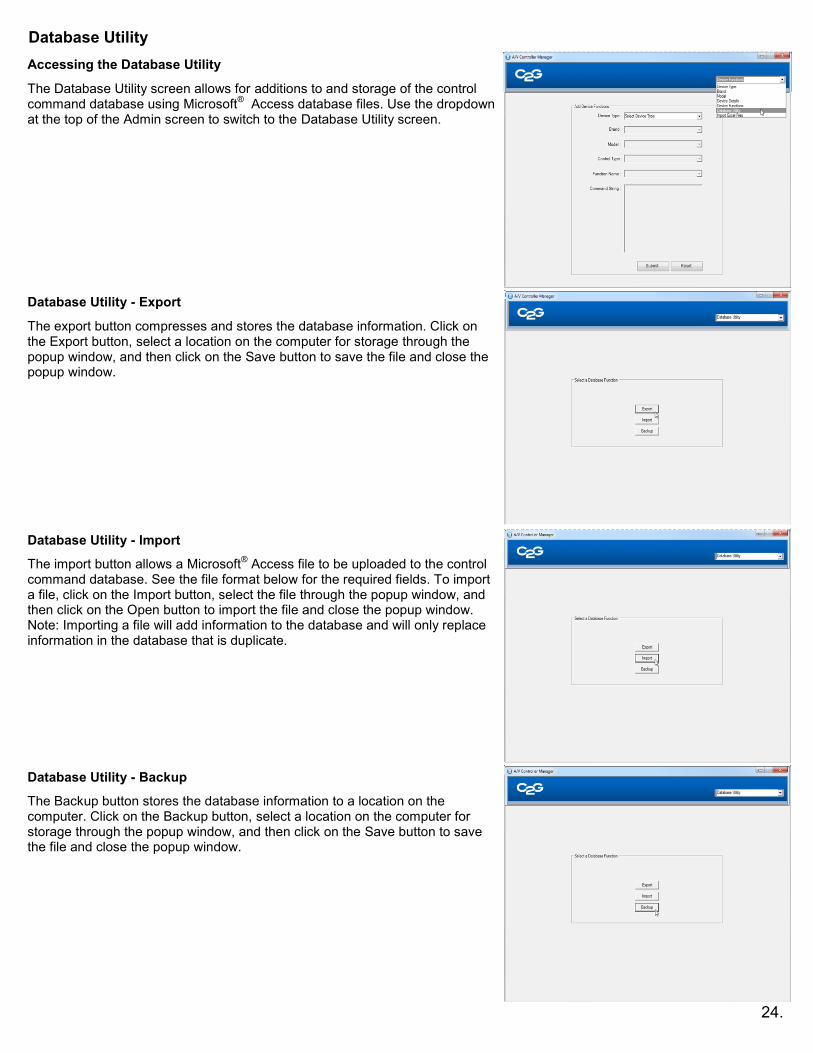
Database Utility
Note A sample file comes with the software The sample file can be modified to create a custom device type data base The sample file is located under CProgramFiles (x86)AV Controller Manager4200W-Serialxlsx When saving the new file ensure that the file name ends with -serialxlsx 1 Device Type should describe the device that is being entered ie Projector Blu-ray Player etc 2 Multiple model numbers should be listed in different cells of column C Adding multiple model number in the same cell will
create an error when importing the data 3 Controller Type can only be Serial or IR 4 List Baud Rate without abbreviations Example 192Kbps should be listed as 19200 5 Columns F to I should only contain one character per cell If the requirement is =None use N 6 Column K will be a combination of upper and lower case letters using the description outlined in the user manual for the
device 7 Column L is for ASCII code only and will not be imported to the database 8 Columns M N and O is for the main code string in Hexadecimal M is used for the Start bit N is used for the main
code and O is for the EndReturn bit
Required fields for Microsoftreg Access and Microsoft
reg Excel files
26
The C2G AV Controller is able to hold up to nine different scripts programmed through the GUI and one script that is reserved for the IR learning function Use the following steps to switch the active script Step 1 Put the controller into administrator mode by connecting a USB Mini A adapter or cable to the USB port on the front of the wall plate controller When in administrator mode all of the buttons will be illuminated blue with the exception of button number 8 which will be illuminated green Step 2 Press and release button number 2 and then enter the code for the desired script (refer to the chart below for script codes) After pressing button number 2 the script code must be entered within 5 seconds or an error will occur indicated by a triple beep and button number 8 which will be illuminated red If an error occurs then the controller will remain in error mode for 15 seconds and then will return to administrator mode and the script change may be attempted again If the script code is entered correctly then the controller will beep button 8 will blink green and the button corresponding to the script will blink twice to confirm the selection After several seconds all keys will illuminate in sequence and the controller will be reset This confirms that the new script is loaded and the controller is ready to use Note Buttons 1 and 8 will blink when script 9 is selected and buttons 2 and 8 will blink twice when script 10 is selected
Script Script Code
Script 1 1 - 1 - 1
Script 2 2 - 2 - 2
Script 3 3 - 3 - 3
Script 4 4 - 4 - 4
Script 5 5 - 5 - 5
Script 6 6 - 6 - 6
Script 7 7 - 7 - 7
Script 8 8 - 8 - 8
Script 9 1 - 1 - 2
Script 10 (IR Learning)
1 - 1 - 3
Changing the Active Script
27
The C2G AV Controller is capable of learning IR commands from a devices remote control through the front of the wall plate Use the following steps to learn IR Commands Step 1 Put the controller into administrator mode by connecting a USB Mini A adapter or cable to the USB port on the front of the wall plate controller When in administrator mode all of the buttons will be illuminated blue with the exception of button number 8 which will be illuminated green Step 2 Press and release button number 4 to enter IR learning mode After pressing button number 4 all buttons will dim and then button 8 will illuminate green when the controller is ready to proceed Step 3 Press and release the button that is to be programmed within 10 seconds of button 8 illuminating green The button that was pressed will be illuminated blue as well as the top button 1 or 2 of the opposite column of buttons This indicates that the button will be programmed with one command Press and release the button that is being programmed up to three additional times to increase the number of commands that will be programmed to that button Step 4 After the proper number of commands have been selected wait five seconds and then the top button 1 or 2 in the column opposite of the button being programmed will begin blinking indicating that the controller is ready to learn the first command Step 5 Point the devices remote control at the IR window on the wall plate controller and press the button on the remote control for the command that will be learned When the command is learned the controller will beep once and the top button 1 or 2 in the column opposite of the button being programmed will stop blinking indicating that the code has been successfully learned The next button down in the column opposite of the button being programmed will begin blinking indicating that the controller is ready to learn the next command Repeat this process until the last command has been learned Step 6 Once the last command has been learned all buttons will dim except for the button that is being programmed which will being blinking and continue to blink for eight seconds During this time the blinking button may be pressed and held for five seconds to set the button press option
If a single command is learnedhellip
the default button press option setting is Single In this mode each press of the button will fire the command
and the blinking button is pressed and held for five seconds then the button press option will be set to Repeat In this mode holding down the button will repeatedly fire the command until the button is released This is typically used for volume controls
If multiple commands are learnedhellip
the default button press option setting is Sequential In this mode each press of the button will fire the next command in the stack After the last command has been fired the next button press will perform the first command in the stack
and the blinking button is pressed and held for five seconds then the button press option will be set to Fire-All In this mode each press of the button will fire all commands in the stack
Once eight seconds have elapsed or the button being programmed has been pressed and held the controller will beep and all buttons will be illuminated blue with the exception of button 8 which will be illuminated green Step 7 Repeat steps 1 through 6 for each button that is to be programmed through IR learning Step 8 Once all buttons have been programmed switch to script 10 where the IR learning information is stored Use the following steps to select script 10
Insert the mini-A USB adapter into the USB port on the front of the controller The controller will enter Admin mode indicated by button 8 being illuminated green
Push button 2 to enter script selection mode
Within 5 seconds of pushing button 2 push the sequence 1 - 1 - 3 to select script 10
If the script code is entered correctly then the controller will beep button 8 will blink green and then button 8 and 2 will blink twice to confirm the selection
Remove the Mini-A USB adapter to resume normal operation using script 10 See the Changing scripts from the controller keypad section for specific instructions on changing scripts If the button that is to be programmed is not pressed then the controller will present an error The controller will beep twice button 8 will blink red and then the controller will return to administrator mode After an error these steps will have to be repeated to enter IR learning mode and learn IR commands
IR Learning Direct To The Face Plate
28
The C2G AV Controller features USB On-The-Go which allows scripts to be uploaded or downloaded from a USB thumb drive Uploading a script to the controller Note The script that is uploaded from a USB thumb drive to the controller will overwrite the active script Use the instructions in the Changing scripts from the controller keypad section to select an empty script or a script that may be overwritten before uploading from a USB thumbdrive Note When saving a script file to the USB thumb drive it must be saved within a specific folder named script and with a specific name scenarioxml If the file is not saved in the required format then it will not be possible to upload the file The following path must be used for saving the file
scriptscenarioxml
If the script is downloaded of another C2G AV Controller then it will automatically be placed in this path with these names Use the following steps to upload a script to the controller Step 1 Save a script file to a USB thumb drive from a computer to the path scriptscenarioxml or download a script from another C2G AV Controller Step 2 Connect the USB thumb drive to the USB A female port of a USB A female to USB Mini A male adapter or adapter cable and then connect the adapter or adapter cable to the USB port on the front of the wall plate controller Once connected the controller will enter Admin mode indicated by button 8 which will be illuminated green Step 3 Press and release button 1 to begin the upload process After a few seconds the buttons will repeatedly light in the following sequence 7 5 3 1 which will indicate uploading The controller will beep and the buttons will stop blinking to indicate that the upload is complete Step 4 Disconnect the adapter or adapter cable from the controller to return to normal operation Downloading a script from the controller Note The controller will download the active script only Use the following steps to download a script from the controller Use the instructions in the Changing scripts from the controller keypad section to select the script that will be downloaded Step 1 Connect the USB thumb drive to the USB A female port of a USB A female to USB Mini A male adapter or adapter cable and then connect the adapter or adapter cable to the USB port on the front of the wall plate controller Once connected the controller will enter Admin mode indicated by button 8 which will be illuminated green Step 2 Press and release button 3 to begin the download process After a few seconds the buttons will repeatedly light in the following sequence 1 3 5 7 which will indicate downloading The controller will beep and the buttons will stop blinking to indicate that the download is complete Step 3 Disconnect the adapter or the adapter cable from the controller to return to normal operation
29
The C2G AV Controller contains a CR1225 battery that support the real-time clock operation for timed events The battery is located between the main PCB of the wall plate controller and the daughter board PCB at the top of the wall plate Use the following steps to replace the battery Warning Ensure that the controller is disconnected from power before replacing the battery Failure to do so may result in damage to the controller Step 1 Remove the wall plate from its mounting location and disconnect the Cat5E cable Step 2 Locate and remove the battery The battery is located between the main PCB of the wall plate controller and the daughter board PCB at the top of the wall plate Note To avoid damage to the controller use a small non-conductive object to remove the battery Step 3 Insert a new battery size CR1225 into the wall plate controller The positive side of the battery should face the main PCB and the front of the wall plate controller Step 4 Reconnect the Cat5E cable and mount the wall plate Caution There is a risk of explosion if the battery is replaced by an incorrect type Dispose of old batteries in accordance with local laws
Changing the Battery
Use the following instructions to change the buttons on the wall plate controller Step 1 Remove the wall plate from its mounting location and disconnect the Cat5E cable Step 2 From the back of the wall plate controller push down on the key plate retaining tab and then toward the front of the wall plate Step 3 Once the top retaining tab is loose carefully remove the key plate from the wall plate controller Step 4 Choose the buttons that will be used and tear them from the button sheet Step 5 Arrange the buttons in the holes of the key plate Step 6 Insert the bottom tab of the key plate into the hole at the bottom of the PCB Be sure that the opening for the USB port aligns with the USB port on the PCB Step 7 Push the top of the key plate toward the PCB until the key plate locks into place Step 8 Reconnect the Cat5E cable and mount the wall plate
Changing the buttons
30
Updating the firmware of the AV Controller may be required occasionally Use the following steps to update the firmware Note Copy the entire Firmware folder from CProgram Files (x86)AV Controller Manager onto a USB thumb drive Make sure no other file folders have firmware in the file name on the thumb drive Use the following steps to update the firmware of the controller Step 1 Save the firmware folder to a USB thumb drive from a computer with the AV Controller software Step 2 Connect the USB thumb drive to the USB A female port of a USB A female to USB Mini A male adapter or adapter cable and then connect the adapter or adapter cable to the USB port on the front of the wall plate controller Once connected the controller will enter Admin mode indicated by button 8 which will be illuminated green Step 3 Press and release button 7 to begin the update process After a few seconds the buttons will repeatedly light in the following sequence 7 5 3 1 which will indicate updating The controller will beep and the buttons will stop blinking to indicate that the update is complete Step 4 Disconnect the adapter or adapter cable from the controller to return to normal operation
Firmware Update Procedure
31
1 The serial codes that I entered are not working What can I do 2 The make and model of my serial or IR device is not listed how can I add it 3 Where can I get a replacement USB mini-A adapter in order to access admin mode 4 How can I change the active script that I am using 5 I am receiving an error when trying to upload a script from a USB thumbdrive What is the problem 6 The controller is not lighting up blue What is the problem 7 Where can I get a serial cable to go from the MCIA to my projector 8 How can I extend the IR emitter cable longer than the 9 foot cable provided 9 How do I locate the serial codes for my device 10 How do I load the same script onto other controllers 11 The controller is not being recognized by the software What can I do 12 I am receiving an error when uploading firmware from a USB thumbdrive What is the problem 13 I am receiving an error when downloading a script to a USB thumbdrive What is the problem 14 I am receiving an error when attempting to learn IR commands through the face plate What is the problem 1 The serial codes that I entered are not working What can I do
Please make sure that the serial codes are entered in Hexadecimal format and not ASCII If the serial codes are provided in ASCII format then they will need to be converted to Hexadecimal
Verify that the baud rate is set correctly for the model of projector
Make certain the serial cable being used is the correct pinout for the projector
If the cable is a straight through serial cable and the projector requires null modem then use the dip switches on the MCIA adapter to reverse the pinout of the cable
2 The make and model of my serial or IR device is not listed how can I add it
If a device is not listed in the pre-configured devices then it must be manually addedPlease click on the admin tab login and then follow the instructions on Adding a DeviceEach IR or serial command that will be used for that device must be added through the Adding a Device screen
3 Where can I get a replacement USB mini-A adapter in order to access admin mode
Please contact us at 800-506-9607 in order to obtain a replacement USB mini-A adapter Two options are available
40346 - USB A Female to USB Mini-A Male Adapter
40347 - 1m USB A Female to USB Mini-A Male Adapter Cable 4 How can I change the active script that I am using
Please refer to the Changing scripts from the controller keypad section
5 I am receiving an error when trying to upload a script from a USB drive What is the problem There may be a few issues that would cause this problem
Ensure that the script file is saved on the USB thumbdrive in the proper folder and that it is named properly The file must be saved to the following folder with the following name scriptscenarioxml
Ensure that the USB OTG upload procedures are followed See the USB OTG section for upload procedures
Ensure that the USB thumbdrive is known good and working Test with a different USB thumbdrive if available
6 The controller is not lighting up blue What is the problem
Make sure the controller is connected to the MCIA adapter with a known good Cat5E cable Verify that the Cat5E cable is good by testing that cable with a continuity tester or a different Cat5E cable
Make sure the MCIA adapter is connected to power The power cable should be plugged into the MCIA on one end and then connected to a power outlet or the C2G Audio Amplifier
Test an additional wall plate controller MCIA adapter or power adaptercable it in the same configuration (If available)
7 Where can I get a serial cable to go from the MCIA to my projector
That depends upon the serial connector on the projector If the serial connection on the projector is a DB9 port then we offer a wide selection of cables that may be used If the serial connection on the projector is a different connector than a DB9 then contact us at 800-506-9607 to see if we carry or if we can make the cable for the projector
FAQTroubleshooting
32
8 How can I extend the IR emitter cable longer than the 9 foot cable provided There are 2 ways to extend the IR emitters 1 A 35mm mono extension cable may be used to extend the IR emitter up to 25ft 2 The screw terminal block that connects to the IR2 port on the side of the MCIA adapter may be used to extend the
IR emitter up to 50ft This extension requires a cable that has at least 2 conductors (ie a Cat5E cable) and a 2-conductor 35mm keystone jack similar to our item 37035 Use the following steps to extend the IR emitter from the screw terminal
Remove the green screw terminal block connector from the controllers packaging
Select a bulk cable that has a least 2 conductors with at minimum wire gauge of 24AWG ie Cat5E cable at the
appropriate length for the IR emitter extension up to 50ft
Insert and secure the conductors into the two opening of the screw terminal block
Secure the other end of the conductors into the back of the keystone jack 37035
To terminate to the keystone jack push down on the orange tabs and insert the wires The left side
(screw facing up) conductor of the screw terminal block connects to the positive (+) position on the keystone and the right side (screw facing up) conductor of the screw terminal block connects to the Negative (-) position on the keystone
Connect the IR emitter cable to the 35mm female port on the keystone jack remove the adhesive cover
from the IR emitter head and then stick the IR emitter heard on the IR receive of the device to be controlled
9 How do I locate the serial codes for my device
This can be commonly found in the manual of the device If this information is not included in the manual then contact the manufacturer of the device to obtain the serial codes
10 How do I load the same script onto other controllers
Once the script has been created in the Button Setting section of the software it can be saved onto a USB thumbdrive and
uploaded to other controllers
It is also possible to download the active script from one controller and then upload it to another controller Please see the
upload and download steps in the USB OTG section for specific instructions on this process
11 The controller is not being recognized by the software What can I do
Verify that the USB cable used to connect the controller to the computers USB port is known good Test with an alternate
USB cable if available
Verify that the controller is connected to power through the MCIA adapter All of the buttons on the controller should be
illuminated blue If the buttons are not illuminated blue then see question 9 for possible solutions
If the software was started before the controller was connected to the computer then the controller will not be recognized
To correct this issue disconnect the controller shut down the software reconnect the controller and then start the software
Verify that the controller is being recognized by the computer While the controller is connected to the computer open
Windows Device Manger The AV Controller should be listed the category of libusb-win32 devices as Audio Video Controller
12 I am receiving an error when uploading firmware from a USB thumbdrive What is the problem
There may be a few issues that would cause this problem
Ensure that the firmware file is saved on the USB thumbdrive in the proper folder and that it is named properly
The file must be saved to the following folder with the following name firmwarefirmwaredfu
Ensure that the firmware update procedures are followed See the Firmware Update section for the update
process
Ensure that the USB thumbdrive is known good and working Test with a different USB thumbdrive if available
13 I am receiving an error when downloading a script to a USB thumbdrive What is the problem
There may be a couple of issues that would cause this problem
Ensure that the script download procedures are followed See the USB OTG section for specific instructions on
this process
Ensure that the USB thumbdrive is known good and working Test with a different USB thumbdrive if available
14 I am receiving an error when attempting to learn IR commands through the face plate What is the problem
There may be a few issues that would cause this problem
Ensure that the procedures in the IR learning through the face plate are followed See the IR Learning through the
face plate for specific instructions on this process
When IR Learning mode has been initiated the key that will be programmed must be pressed within 10 seconds
If this key is not pressed then the controller will present an error
Once the controller has indicated that it is ready to learn an IR command the command must be sent within 20
seconds If the command is not sent then the controller will present an error
FAQTroubleshooting
33