4024 ieee journal on selected areas in …web.stanford.edu/~x23wu/stac.pdf · stac: simultaneous...
TRANSCRIPT

4024 IEEE JOURNAL ON SELECTED AREAS IN COMMUNICATIONS, VOL. 34, NO. 12, DECEMBER 2016
STAC: Simultaneous Transmitting andAir Computing in Wireless Data Center Networks
Xiugang Wu, Member, IEEE, Shengli Zhang, Member, IEEE, and Ayfer Özgür, Member, IEEE
Abstract— The data center network (DCN), wired or wireless,features large amounts of many-to-one (M2O) sessions. EachM2O session is currently established using point-to-point (P2P)communications and store-and-forward (SAF) relays, and isgenerally followed by a certain computation at the destination,typically a weighted summation of the received information digits.Fundamentally different from this separate P2P/SAF-based-transmission and computation framework, this paper proposessimultaneous transmission and air computation (STAC), a novelphysical layer scheme that achieves STAC in wireless DCNs.In particular, STAC builds on a number of distinguishing char-acteristics of DCs to take advantage of the superposition natureof electromagnetic signals. With STAC, multiple sources transmitin the same time slot with appropriately chosen parameters, suchthat the superimposed signal can be directly transformed to thedesired summation at the receiver. To enable STAC, we proposean enhanced software-defined network architecture, where awired low-bandwidth backbone provides wireless transceiverswith external reference signals. We also discuss some new chal-lenges that STAC brings to scheduling and routing. Theoreticalanalysis and simulation results show that STAC can significantlyimprove both bandwidth and energy efficiency in DCNs.
Index Terms— Data center network, green communications,software defined network, wireless network.
I. INTRODUCTION
AMODERN Data Center (DC) typically consists of a largededicated cluster of commercial computers (work nodes)
that are housed together to store/process big files in a parallelmanner. The parallel storage/processing of the files necessi-tates frequent communication among the work nodes, whichis accomplished through the Data Center Network (DCN).Despite the maturity in deployment and their high bandwidth,there are a few critical problems associated with wired DCNs,such as limited flexibility, cabling complexity, device cost,over subscription, etc. These problems significantly limit thescalability of DCNs and are being exacerbated by the huge
Manuscript received February 1, 2016; revised July 18, 2016; acceptedAugust 23, 2016. Date of publication September 20, 2016; date of currentversion December 29, 2016. This work was supported in part the National973 Project under Grant 2013CB336700, in part by the Chinese NSF Projectunder Grant 61372078, and in part by the Shenzhen NSF Project underGrant JCYJ20160226192223251. This paper was presented at the IEEE/CICInternational Conference on Communications in China, Shenzhen, China,November 2015 [1]. (Corresponding author: Shengli Zhang.)
X. Wu and A. Özgür are with the Department of Electrical Engineering,Stanford University, Stanford, CA 94305 USA (e-mail: [email protected];[email protected]).
S. Zhang is with the Faculty of Information Engineering, Shenzhen Univer-sity, Shenzhen 518060, China (e-mail: [email protected]).
Color versions of one or more of the figures in this paper are availableonline at http://ieeexplore.ieee.org.
Digital Object Identifier 10.1109/JSAC.2016.2611838
amount of data that needs to be stored/processed within a DCand exchanged through the DCN in today’s age of big data.
To overcome these limitations, recent works [2]–[7] haveexplored the possibility of constructing wireless DCNs usinghigh frequency electromagnetic (EM) signalling. Although thedata rate of wireless links is still currently lower than thatof wireline links, wireless transmission techniques have beenunder rapid development, and particularly, 60 GHz techniqueshave been proposed for realizing wireless DCN links withbandwidth comparable to wireline connections in [2] and [3],while the blockage and directivity problems associated withEM waves can be significantly mitigated by utilizing strategieslike ceiling reflection and 3D beamforming [4]. Free-spaceoptical DCN communication has also been investigated [5],and shown to achieve further improvements in bandwidth, aswell as nearly perfect directivity which helps to significantlyreduce interference in the wireless DCN and protect the uplayer rate from being dramatically decreased. On the otherhand, [6] considers augmenting the wired DCN with wirelessflyways, and [7] demonstrates that a completely wireless DCNwith a Cayley structure is feasible and performs even betterthan a wired DCN.
A. Challenging the P2P and SAF Paradigm
This paper aims to further the research of wireless DCNsby challenging two of its fundamental assumptions, namely,Point-to-Point (P2P) communication and Store-and-Forward(SAF) relaying. These two paradigms form the basis oftoday’s ubiquitous wireless networks, e.g., cellular and 802.11networks, and are also widely adopted as the assumptions inthe literature on wireless DCNs [8], [9]; however, here weargue that they may be highly suboptimal for DCNs due to anumber of distinguishing characteristics of the traffic and thecomputations typically occurring within DCs.
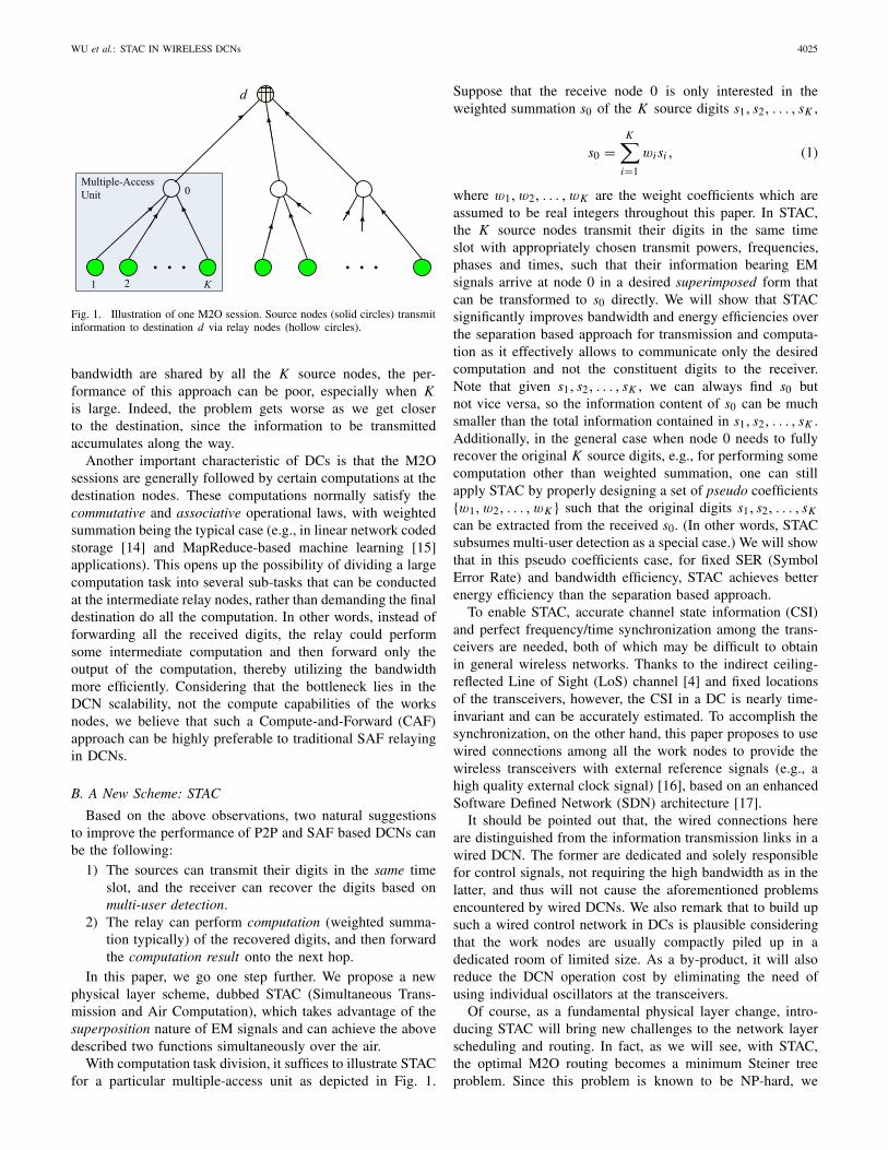
First, the DCNs feature a large number of Many-to-One (M2O) sessions arising from various DC applications,e.g., Google File System (GFS) [10] and MapReduce [11].Due to the limited transmission range of high frequency EMwaves, these M2O sessions are established through multi-hopping over hierarchical multiple-access units [12], [13] asshown in Fig. 1, where each hop is based on P2P com-munication followed by SAF relaying onto the next hop.Specifically, with Time Division Multiple-Access (TDMA)inside the multiple-access unit, the source nodes 1, 2, . . . , Ksuccessively transmit their information to the relay node 0 indifferent time slots via P2P transmissions, and the relay storesthe received information in its buffer before forwarding themto the destination d . Since node 0’s buffer and input/output
0733-8716 © 2016 IEEE. Personal use is permitted, but republication/redistribution requires IEEE permission.See http://www.ieee.org/publications_standards/publications/rights/index.html for more information.
WU et al.: STAC IN WIRELESS DCNs 4025
Fig. 1. Illustration of one M2O session. Source nodes (solid circles) transmitinformation to destination d via relay nodes (hollow circles).
bandwidth are shared by all the K source nodes, the per-formance of this approach can be poor, especially when Kis large. Indeed, the problem gets worse as we get closerto the destination, since the information to be transmittedaccumulates along the way.
Another important characteristic of DCs is that the M2Osessions are generally followed by certain computations at thedestination nodes. These computations normally satisfy thecommutative and associative operational laws, with weightedsummation being the typical case (e.g., in linear network codedstorage [14] and MapReduce-based machine learning [15]applications). This opens up the possibility of dividing a largecomputation task into several sub-tasks that can be conductedat the intermediate relay nodes, rather than demanding the finaldestination do all the computation. In other words, instead offorwarding all the received digits, the relay could performsome intermediate computation and then forward only theoutput of the computation, thereby utilizing the bandwidthmore efficiently. Considering that the bottleneck lies in theDCN scalability, not the compute capabilities of the worksnodes, we believe that such a Compute-and-Forward (CAF)approach can be highly preferable to traditional SAF relayingin DCNs.
B. A New Scheme: STAC
Based on the above observations, two natural suggestionsto improve the performance of P2P and SAF based DCNs canbe the following:
1) The sources can transmit their digits in the same timeslot, and the receiver can recover the digits based onmulti-user detection.
2) The relay can perform computation (weighted summa-tion typically) of the recovered digits, and then forwardthe computation result onto the next hop.
In this paper, we go one step further. We propose a newphysical layer scheme, dubbed STAC (Simultaneous Trans-mission and Air Computation), which takes advantage of thesuperposition nature of EM signals and can achieve the abovedescribed two functions simultaneously over the air.
With computation task division, it suffices to illustrate STACfor a particular multiple-access unit as depicted in Fig. 1.
Suppose that the receive node 0 is only interested in theweighted summation s0 of the K source digits s1, s2, . . . , sK ,
s0 =K∑
i=1
wi si , (1)
where w1, w2, . . . , wK are the weight coefficients which areassumed to be real integers throughout this paper. In STAC,the K source nodes transmit their digits in the same timeslot with appropriately chosen transmit powers, frequencies,phases and times, such that their information bearing EMsignals arrive at node 0 in a desired superimposed form thatcan be transformed to s0 directly. We will show that STACsignificantly improves bandwidth and energy efficiencies overthe separation based approach for transmission and computa-tion as it effectively allows to communicate only the desiredcomputation and not the constituent digits to the receiver.Note that given s1, s2, . . . , sK , we can always find s0 butnot vice versa, so the information content of s0 can be muchsmaller than the total information contained in s1, s2, . . . , sK .Additionally, in the general case when node 0 needs to fullyrecover the original K source digits, e.g., for performing somecomputation other than weighted summation, one can stillapply STAC by properly designing a set of pseudo coefficients{w1, w2, . . . , wK } such that the original digits s1, s2, . . . , sK
can be extracted from the received s0. (In other words, STACsubsumes multi-user detection as a special case.) We will showthat in this pseudo coefficients case, for fixed SER (SymbolError Rate) and bandwidth efficiency, STAC achieves betterenergy efficiency than the separation based approach.
To enable STAC, accurate channel state information (CSI)and perfect frequency/time synchronization among the trans-ceivers are needed, both of which may be difficult to obtainin general wireless networks. Thanks to the indirect ceiling-reflected Line of Sight (LoS) channel [4] and fixed locationsof the transceivers, however, the CSI in a DC is nearly time-invariant and can be accurately estimated. To accomplish thesynchronization, on the other hand, this paper proposes to usewired connections among all the work nodes to provide thewireless transceivers with external reference signals (e.g., ahigh quality external clock signal) [16], based on an enhancedSoftware Defined Network (SDN) architecture [17].
It should be pointed out that, the wired connections hereare distinguished from the information transmission links in awired DCN. The former are dedicated and solely responsiblefor control signals, not requiring the high bandwidth as in thelatter, and thus will not cause the aforementioned problemsencountered by wired DCNs. We also remark that to build upsuch a wired control network in DCs is plausible consideringthat the work nodes are usually compactly piled up in adedicated room of limited size. As a by-product, it will alsoreduce the DCN operation cost by eliminating the need ofusing individual oscillators at the transceivers.
Of course, as a fundamental physical layer change, intro-ducing STAC will bring new challenges to the network layerscheduling and routing. In fact, as we will see, with STAC,the optimal M2O routing becomes a minimum Steiner treeproblem. Since this problem is known to be NP-hard, we

4026 IEEE JOURNAL ON SELECTED AREAS IN COMMUNICATIONS, VOL. 34, NO. 12, DECEMBER 2016
Algorithm 1 Network Coded Recovery
1: s0 =∑Ki=1 wi si
2: s0 ← s0 mod 2q
develop a greedy single-M2O session routing algorithm, anduse it in the case of multiple M2O sessions to demonstrate thenetwork gain brought by STAC.
The remainder of the paper is organized as follows. First,Section II presents some motivating examples, followed bya detailed description of the STAC system architecture inSection III. Then, Sections IV and V discuss the techni-cal issues and performance improvements at the physicallayer and the network layer, respectively. Finally, SectionVI concludes the paper and proposes some future researchdirections.
II. MOTIVATING EXAMPLES
Two major DC applications are i) distributed file stor-age, e.g., GFS [10] and Hadoop Distributed File System(HDFS) [18], and ii) parallel big data processing based onthe MapReduce model [11]. We now present three detailedDC application examples mentioned in Section I that motivateSTAC, where the first two correspond to GFS and MapReduce,respectively, and the last one shows the flexibility of STACfor general applications. Again, with task division, we canconcentrate our discussion on the multiple-access unit depictedin Fig. 1.
A. Network Coded Storage
Due to the non-negligible node failures in a DC [10], indistributed storage systems, a big file is usually divided intomany fixed-length data blocks that are further protected bymultiple replicas stored at different work nodes.
For storage efficiency, a network code can be applied [14],[19], [20], where each node stores network coded blocksinstead of raw data. When a coded block is lost due toa node failure, it can be reconstructed at another node byperforming Algorithm 1 on a digit-by-digit basis, where s0denotes a digit from the lost coded block requiring recovery,s1, s2, . . . , sK are digits from the data blocks stored at the othernodes, w1, w2, . . . , wK are the network coding coefficients,and the modulo operation is due to the finite field size 2q .Clearly, with STAC, we can achieve Step 1 of the algorithmdirectly.
B. MapReduce Based Data Processing
In MapReduce model, when the map nodes finish theprocessing, their outputs with the same key will be sentto a specified reduce node for the final computations. Suchcomputations are also typically in the form of weightedsummations [11], [21], e.g., for all machine leaning algorithmsfitting the statistical query model [15], scientific processes[22], [23], documents similarity comparisons [24], etc. Again,STAC can be applied to achieve simultaneous transmissionand computation here.
Algorithm 2 Source Digits Extraction1: i ← 12: while i ≤ K do3: si ← s0 mod 2q
4: s0 ← (s0 − si )/2q
5: i ← i + 16: end while
C. General Case
When the receive node 0 needs the original source digits,one can appropriately design a set of pseudo coefficients{w1, w2, . . . , wK } such that the source digits s1, s2, . . . , sK
can be extracted from s0. In particular, suppose for eachi = 1, 2, . . . , K ,
0 ≤ si ≤ 2q − 1,
then choosing wi = 2q(i−1) yields
s0 =K∑
i=1
2q(i−1)si ,
based on which all the source digits can be extracted withAlgorithm 2.
To conclude this section, we point out that STAC can have awide range of applications in addition to the above examples.For example, although our motivation for proposing STACmainly comes from M2O sessions that include the aboveexamples as special cases, it can also be applied to P2P orM2M (Many-to-Many) situations with the idea of combiningor splitting sessions as discussed in [25]. Also, note thatalthough this paper focuses on wireless DCNs, the applicationof STAC may not be restricted to DCs. In fact, it can be appliedto any general wireless networks with MapReduce or Hadoopapplications [26], or wireless sensor networks where the sensornodes need to finish some computation task in a cooperativeway [27].
III. SYSTEM ARCHITECTURE WITH STAC
This section describes the system architecture with STAC.We first introduce the principle of a basic STAC unit, andthen propose an enhanced SDN architecture that enables thefunctioning of DCNs with STAC units.
A. A Basic STAC Unit
STAC is a general physical layer scheme that can be appliedto wireless DCs with any structure, carrier frequency, etc.For illustration, consider a typical layout of the wirelessDC as shown in Fig. 2, where each rack contains multiplework nodes and has an antenna array mounted on its top tocommunicate with other racks (communications within a rackare accomplished with intra-rack connections) [7]. As in [4],ceiling-reflecting and 3D beamforming techniques are adoptedto achieve an indirect LoS link between any two antenna arrayswithout causing interference to others.
Suppose K work nodes (in K different racks) need totransmit their digits s1, s2, . . . , sK to node 0 for computing

WU et al.: STAC IN WIRELESS DCNs 4027
Fig. 2. A typical wireless DC layout.
the weighted summation as in (1). The operating principle ofSTAC is illustrated in the following.
Each source node i maps its digit si to a baseband modu-lated complex symbol di , and then up converts the symbol di
to a passband signal given by√
Pi e− jθi di (t)e
− j fct ,
where θi and√
Pi are the pre-equalizing phase and amplitudecoefficients, respectively. Suppose each node i transmits attime ti using 3D beamforming, then the received passbandsignal y(t) can be expressed as
K∑
i=1
hi ejθ ′i
√Pi e− jθi di (t − ti − τi )e
− j fc(t−ti−τi ) + n(t)
where hi e jθ ′i is the equivalent complex channel coefficientfrom node i to 0, τi is the propagation delay for node i , andn(t) is a Gaussian noise of variance σ 2 for both the real andimaginary dimensions. With accurate CSI, one can set
θ ′i = θi and ti = t0 − τi , (2)
such that the received signal simplifies to
y(t) =K∑
i=1
hi
√Pi di (t − t0)e
− j fc(t−t0) + n(t),
which, after down conversion and sampling at time t = t0,yields the baseband symbol1
y =K∑
i=1
hi
√Pi di + n, (3)
where n ∼ N (0, σ 2). Clearly, if each node i sets
Pi = (wi/hi )2, (4)
then after eliminating the noise, node 0 can construct thedesired digit s0 as in (1) from the symbol y in (3).
1The hi in (3) are real variables, so that the real and imaginary partsof symbol y can be separated. In this paper, we only consider the realpart for simplicity. In general, complex signals are more complicated whensuperimposed. However, we assume phase synchronization in STAC, whereall the complex signals are superimposed in a synchronized version. In otherwords, the real parts and the imaginary parts of the signals are summedseparately. By precoding the imaginary part and real part with their owncalculated coefficients, two summed symbols can be obtained at the receiver,from the real and imaginary parts respectively.
Fig. 3. An enhanced SDN architecture.
With the above described principle, one can see that thetime/frequency synchronization and pre-equalization, such as(2) and (4), are essential for STAC, and synchronization failureand channel impairments may severely degrade the perfor-mance of STAC. These synchronization and pre-equalizationissues may not be easy to resolve in general [28], [29],however in DCs the transceiver and environment are typicallystatic, and there is only LoS (Line-of-Sight) propagationpath, i.e., no reflection, no multi-path and no interference.Under this circumstance, one can relatively easily achieve thesynchronization and pre-equalization by using an enhancedSDN architecture as we discuss next.
B. An Enhanced SDN Architecture
The DC generally work based on centralized control, wherethe front servers, including the job scheduler and data manager,control all the work nodes. In current DCNs, control signalsand data traffic share the same network. Here, we propose touse a dedicated low bandwidth wired control network withan added network server as shown in Fig. 3, based on anenhanced SDN architecture. As mentioned in Section I, thewired control network is feasible due to limited DC size andfixed node locations.
Our SDN architecture is an enhanced one in the sense that,it not only accomplishes networking control as in generalSDNs, but also also provides the wireless transceivers thephysical and upper layer configurations to enable STAC,including the synchronization information, the physical layerparameters such as powers, frequencies, phases and times, andthe scheduling/routing information.
Synchronization with External Reference Signals: Externalreference signals are provided to all the transceivers for syn-chronization. These include a high quality external clock sig-nal, with which individual crystal oscillators at the transceiversare no longer needed and the operation cost can be therebyreduced. These reference signals can also help calibrate thewireless transceivers, e.g., reduce the errors induced from thedevice hardware differences [16].
Physical Layer Parameters: The network server maintainsa connection information table that stores important physicallayer parameters for each connection, such as the transmissiondelay τ , channel coefficient he− jθ and the steering vec-tors required for 3D beamforming. When a transceiver fails

4028 IEEE JOURNAL ON SELECTED AREAS IN COMMUNICATIONS, VOL. 34, NO. 12, DECEMBER 2016
(or a new one comes in), it informs the network server throughthe control network and the connection information table isupdated.
Scheduling/Routing: Also maintained by the network serveris a table storing the scheduling/routing information. Whena current task finishes or a new one needs to start, the jobscheduler informs the network server to update the schedul-ing/routing information table. Then the network server initiatesthe needed coordinations between the work nodes involved.
Difference From Traditional SDN: Note that the traditionalSDN, which centralizedly control the routings and switchesin the network, has already been deployed in current wiredDCN to manage the data flows at the network layer. In STAC,the physical layer transmissions are much more complex andimportant, and we extend the concepts of SDN to the physi-cal layer. Specifically, there are two fundamental extensions.i) The OpenFlow [30] interface between the controller andthe node (end node and routing node) should be extendedto include the physical transmission parameters, such as thetransmission time, coefficients, beamforming direction and soon. The physical parameters can be initially obtained whena wireless transceiver joins the network with measuring thechannels between the transceiver and its neighbors (thereis a direct link between them). Note that the complexityof this procedure is fixed for any size of network as theneighbor number is almost fixed and the channel conditionsare almost static. In OpenFlow, the flows are first identified bymatching to their head information before they are forwardedaccordingly. Both the head information and the forward rulesare pre-determined by the controller. In our scheme, we needto add the physical layer head information, such as transceiveraddress and channel into the match field. We also need toadd the physical transmission parameters into the forwardrule. ii) The controller should provide synchronization signals,such as an external clock signal, to provide a master-slavetype synchronization service to all the wireless transceivers.Specifically, the external clock signal can help to guaranteesynchronized frequency and clock steps. The controller canalso periodically send time synchronize packets in a master-slave manner as in [31] to obtain initial time synchronizationand to deal with other synchronization errors.
Another feature of our enhanced SDN is that we usewireless channels for the data transmission and wired channelfor the control network. This is because control informationis typically light but periodical and static, and therefore wecan simply connect the transceivers directly with wirelineswithout using expensive and high-energy-cost switches. On theother hand, wireless transmissions, with increasing rate andunlimited bandwidth inside the DC, are more appropriate forheavy and random data traffics.
IV. PHYSICAL LAYER ISSUES
A. Modulation-Demodulation Mapping
The modulation for STAC is the same as that for P2Pchannels. However, their demodulation mappings are subtlydifferent: STAC demodulation maps a superimposed symbol,which may even not belong to the transmit symbol sets,
to the summation of the digits, whereas the P2P channeldemodulation maps a particular symbol from the transmitsymbol set to the corresponding digit.
1) STAC Modulation: Specifically, writing node i ’s digit si
into the bit sequence form yields
[si (1), si (2), . . . , si (l), . . . , si (L)]where si (l) is the l-th bit, L is the sequence length, and
si =L−1∑
l=0
2lsi (l).
For modulation, throughout this paper we assume BPSK(Binary Phase Shift Keying)2 is used without error correctioncoding. At node i , each bit si (l) is modulated to a symboldi (l) ∈ {−1,+1} as di (l) = 1− 2× si (l).
2) STAC Demodulation: After the l-th transmission and theremoval of noise with signal detection, the received superim-posed symbol can be written as
y(l) =K∑
i=1
hi
√Pi di(l) (5)
By setting the transmit power3 Pi = (wi/hi )2, one has
y(l) =K∑
i=1
wi di (l), (6)
which, through the operation
1
2
(K∑
i=1
wi − y(l)
),
yields the summation∑K
i=1 wi si (l).Finally, the desired digit can be constructed as
L−1∑
l=0
2lK∑
i=1
wi si (l) =K∑
i=1
wi
L−1∑
l=0
2l si (l) =K∑
i=1
wi si .
B. Signal Detection
We now present a simple signal detection scheme forremoving the noise in (3) to obtain (5), and analyze itscorresponding SER. It suffices to consider only one of the Ltransmissions, and hence the index l as in the last subsectionwill be omitted.
Specifically, view the symbol∑K
i=1 wi di in (6) as a pointof a non-standard PAM (Pulse Amplitude Modulation) con-stellation that results from the weighted superposition of thetransmit BPSK constellations and hence may have unequal dis-tance between different adjacent constellation points. A simpledetection scheme is to quantize the y in (3) to its nearestconstellation point. Let π be a permutation on {1, 2, . . . , K }
2STAC also applies with other modulations such as QPSK, QAM, OOK,OFDM, etc. This paper only considers the simplest BPSK due to the reasonmentioned in Footnote 1.
3With the unit power of di in BPSK, the transmit power Pi |di |2 simplyequals Pi .

WU et al.: STAC IN WIRELESS DCNs 4029
such that wπ( j1) ≤ wπ( j2), ∀ j1 ≤ j2. We have the followingtheorem regarding the SER with such detection.
Theorem 1: The SER with the nearest point detection isupper bounded by
SERSTAC ≤(
1− 1
2K
)erfc
(1√2σ
)(7)
where erfc(x) = 2√π
∫∞x e−t2
dt is the complementary error
function, σ 2 is the variance of the noise, and the equalityin (7) holds when the distance between any two adjacent con-stellation points is equal to 2, e.g., when wπ( j ) = 2 j−1 or 1,∀ j = 1, . . . , K .
Proof: Recall that we assume BPSK modulation, anddi ∈ {−1, 1},∀i = 1, 2, . . . , K , denotes the transmit symbolof node i . The receive constellation for the superimposedsymbol
∑Ki=1 wi di results from the weighted superposition
of the transmit BPSK constellations of the K nodes, whichdepends on the choice of {w1, w2, . . . , wK }.
Since wi are all real integers, one can easily check thatthe distance between any two adjacent points in the receiveconstellation is at least 2. When this distance is exactly 2, e.g.,when wπ( j ) = 2 j−1 or 1,∀ j = 1, . . . , K , the SER attains itsmaximum value. In this case, the SER for the detection of theleftmost or rightmost point is
SER1 = Pr(n ≥ 1)
= 1√2πσ 2
∫ ∞
1e−t2/(2σ 2) dt
= 1
2erfc
(1√2σ
)
where n is the receive noise as in (3). For the detectionof the other points in the receive constellation, the SER isgiven by
SER2 = Pr(n ≤ −1)+ Pr(n ≥ 1)
= 2× Pr(n ≥ 1)
= erfc
(1√2σ
).
Finally, noting that the leftmost (or rightmost) constellationpoint happens if and only if all di take value −1 (or +1),which is with probability 1
2K , we obtain the following upperbound on the average SER of STAC:
SERSTAC ≤ 2
2K× SER1 +
(1− 2
2K
)× SER2
=(
1− 1
2K
)erfc
(1√2σ
),
which proves the theorem.Note that the nearest point detection is in general suboptimal
due to the possible different weight coefficients. Nevertheless,in the next we will show that even with this suboptimaldetection, STAC outperforms the separate P2P-based trans-mission and computation strategy, where the latter will also bereferred to as separate strategy for convenience in the sequeldiscussion.
C. Performance of STAC
The performance of STAC is a tradeoff among SER, energyefficiency and bandwidth efficiency, and is clearly dependentof the weight coefficients. The air computation essence ofSTAC and its advantage over the separate strategy can be bestillustrated in the ideal case of w1 = w2 = · · · = wK = 1,where we will show that for fixed energy efficiency, STACalways achieves better SER in the high SNR regime andsignificantly improved bandwidth efficiency.
On the other hand, to show that STAC uniformly out-performs the separate strategy, we will consider the pseudocoefficients case as mentioned in Section II, i.e., wπ( j ) =2 j−1,∀ j . The argument here is that by applying STAC withthe pseudo coefficients, one can recover the original K sourcedigits, based on which summation with any weight coefficientscan be computed. We will show that in this case, STACachieves better energy efficiency for fixed SER and bandwidthefficiency.
1) The Ideal Case: Suppose w1 = w2 = · · · = wK = 1.The SER of STAC is given in Theorem 1, i.e.,
SERSTAC =(
1− 1
2K
)erfc
(1√2σ
).
Note that in this case, the resultant receive PAM constellationhas only K + 1, instead of 2K , points,4 where the decreaseof the constellation size is due to the “air computation”.Or equivalently, viewed from the energy perspective, thisadvantage is reflected by the fact that the needed trans-mit power now attains the minimum Pi = 1/h2
i for eachnode i .
For the separate strategy, assume each node i transmits withthe same power Pi = 1/h2
i as in STAC. The SER for node iis a standard result, given by
1
2erfc
(1√2σ
).
Combining all the detected K symbols, the receiver computes∑Ki=1 wi di , and the resultant SERSEP can be lower bounded as
in the following theorem.Theorem 2: The SER with the separate strategy is lower
bounded by
SERSEP ≥ 1
2− 1
2
(1− erfc
(1√2σ
))K
.
Proof: With separate symbol detection, the SER of eachsymbol is 1
2 erfc( 1√2σ
) for BPSK modulation. Since the number
of erroneous symbols is a binomial random variable withparameters (K , 1
2 erfc( 1√2σ
)) and the computation result is
wrong if there are odd number of erroneous symbols, we have
4In particular, the resultant receive PAM constellation is {−K ,−K +2, . . . ,−1, 1, . . . , K − 2, K } when K is odd, and {−K ,−K +2, . . . ,−2, 0, 2, . . . , K − 2, K } when K is even. Note that in eithercase, the size of the constellation is K + 1.

4030 IEEE JOURNAL ON SELECTED AREAS IN COMMUNICATIONS, VOL. 34, NO. 12, DECEMBER 2016
that SERSEP can be lower bounded by
SERSEP ≥�K/2�−1∑
i=0
(K
2i + 1
) (1
2erfc
(1√2σ
))2i+1
×(
1− 1
2erfc
(1√2σ
))K−2i−1
= 1
2− 1
2
(1− erfc
(1√2σ
))K
.
We now show that in the ideal case, for fixed energyefficiency, STAC always achieves better SER than the sep-arate strategy for sufficiently large SNR, in particular, whenerfc( 1√
2σ) < 1
2 .Theorem 3: SERSEP > SERSTAC for any K ≥ 2 provided
erfc( 1√2σ
) < 12 .
Proof: We prove the theorem by mathematical induction.First consider the case of K = 2. Denoting erfc( 1√
2σ) by
p ∈ (0, 0.5), we have
SERSEP ≥ 1
2− 1
2(1− p)2 ,
and
SERSTAC = 3
4p.
Therefore,
SERSEP − SERSTAC ≥ 1
2− 1
2(1− p)2 − 3
4p
= 1
4p(1− 2 p)
> 0.
Now assume that
1
2− 1
2(1− p)K >
(1− 1
2K
)p. (8)
Note that this has been verified for the case when K = 2 andwe will now prove that given (8) holds, one must also have
1
2− 1
2(1− p)K+1 >
(1− 1
2K+1
)p.
For this, consider the following:
1
2− 1
2(1− p)K+1 −
(1− 1
2K+1
)p
= 1
2− 1
2(1− p)K (1− p)−
(1− 1
2K+ 1
2K− 1
2K+1
)p
= 1
2− 1
2(1− p)K −
(1− 1
2K
)p + 1
2(1− p)K p
−(
1
2K− 1
2K+1
)p
>1
2(1− p)K p −
(1
2K− 1
2K+1
)p (9)
= 1
2(1− p)K p − 1
2K+1 p
> 0, (10)
Fig. 4. SER comparison (K = 4).
where (9) follows from the assumption (8), and (10) followssince p < 1
2 . Since we already prove that (8) holds for K = 2,it can be concluded that (8) holds for any K ≥ 2, and thusSERSEP > SERSTAC.
Therefore, STAC achieves a better SER in the high SNRregime and simultaneously improves the bandwidth efficiencyby a factor of K . Especially, note that as K →∞, SERSTAC →erfc(1/
√2σ) whereas SERSEP → 1/2! Fig. 4 plots SERSTAC and
SERSEP for K = 4.2) Pseudo Coefficients Case: Consider a set of pseudo
coefficients wπ( j ) = 2 j−1,∀ j. To minimize the total transmitpower
∑Ki=1(wi/hi )
2 with STAC, we allocate these coeffi-cients among the K nodes such that hπ( j1) ≥ hπ( j2), ∀ j1 ≤ j2.Assuming STAC is completed within unit time, the totaltransmit energy ESTAC is given by
ESTAC =K∑
j=1
(2( j−1)/hπ( j )
)2. (11)
We now calculate the total energy needed ESEP for theseparate strategy assuming that each node transmits 1 bit tothe receiver within 1/K time to maintain the same bandwidthefficiency as STAC. For the separate strategy to achieve thesimilar SER as STAC, the distance between any adjacentreceive constellation points also needs to be 2, in which casenode i ’s transmit power is given by
Pi =K∑
j=1
(2( j−1)/hi
)2.
Therefore, the total energy needed is
ESEP = 1
K
K∑
i=1
K∑
j=1
(2( j−1)/hi
)2 (12)
where the factor 1/K accounts for the transmission time ofeach node.
Theorem 4: ESEP ≥ ESTAC, where the equality holds onlywhen hi are the same for all i .

WU et al.: STAC IN WIRELESS DCNs 4031
Proof: The proof utilizes the important fact that wπ( j1) ≤wπ( j2) and hπ( j1) ≥ hπ( j2), ∀ j1 ≤ j2, and is detailed asfollows.
K ESEP (13)
=K∑
i=1
1/h2i
K∑
j=1
(2( j−1)
)2
=K∑
i=1
1/h2π(i)
K∑
j=1
(2( j−1)
)2
=K∑
i=1
K∑
j=1
1/h2π(i)
(2( j−1)
)2
=K∑
i=1
22(i−1)
h2π(i)
+K∑
i=1
∑
j �=i
22( j−1)
h2π(i)
=K∑
i=1
22(i−1)
h2π(i)
+K∑
i=1
i−1∑
j=1
22( j−1)
h2π(i)
+K∑
i=1
K∑
j=i+1
22( j−1)
h2π(i)
(14)
=K∑
i=1
22(i−1)
h2π(i)
+K∑
i=1
K∑
j=i+1
[22(i−1)
h2π( j )
+ 22( j−1)
h2π(i)
](15)
≥K∑
i=1
22(i−1)
h2π(i)
+K∑
i=1
K∑
j=i+1
[22(i−1)
h2π(i)
+ 22( j−1)
h2π( j )
](16)
=K∑
i=1
22(i−1)
h2π(i)
+K∑
i=1
K∑
j=i+1
22(i−1)
h2π(i)
+K∑
i=1
K∑
j=i+1
22( j−1)
h2π( j )
=K∑
i=1
22(i−1)
h2π(i)
+K∑
i=1
(K − i)22(i−1)
h2π(i)
+K∑
i=1
K∑
j=i+1
22( j−1)
h2π( j )
=K∑
i=1
(K − i)22(i−1)
h2π(i)
+K∑
i=1
i22(i−1)
h2π(i)
= KK∑
i=1
22(i−1)
h2π(i)
= K ESTAC
In the above, (14) follows from splitting the indices j �= iinto two categories: j ∈ {1, 2, . . . , i − 1} and j ∈ {i + 1,i + 2, . . . , K }, and (15) follows from switching the rolesof i and j and then changing the summation order in thesecond term of (14). Finally, inequality (16) can be verifiedby noting that 22( j−1)
h2π(i)+ 22(i−1)
h2π( j)
is always greater than or equal
to 22(i−1)
h2π(i)+ 22( j−1)
h2π( j)
, with the equality holding only when hi are
the same for all i ’s. This also shows that the more diversethe channel coefficients hi are, the more energy can be savedby STAC.
From Theorem 4, it can be concluded that STAC performsuniformly better than the separate strategy for any set ofweight coefficients. This is because even requiring STACto fully recover the original K source digits leads to betterenergy efficiency than the separate strategy, for fixed SER andbandwidth efficiency.
Fig. 5. Energy performance of STAC and the separate strategy.
3) Discussion: The above analyzes two extreme cases ofthe weight coefficients. In general, depending on the specificweight coefficients, one has the freedom of dividing the Knodes into M groups (1 ≤ M ≤ K ), and letting each grouptransmit using STAC separately, to achieve a tradeoff betweenthe bandwidth efficiency and energy efficiency.
Now, it should be clear that our STAC scheme includesboth the separate P2P transmissions and the simultaneoustransmission combined with multi-user detection as specialcases: Choosing M = K and viewing the P2P transmission asa degraded STAC lead to the former, while the latter is simplyequivalent to applying STAC to the pseudo coefficients case.
Fig. 5 plots the normalized transmit energy per node ofSTAC and the separate P2P transmissions, where the channelcoefficients h are assumed to be randomly generated underthe standard Rayleigh distribution. It can be seen that asthe number of sources K increases, the normalized transmitenergy of STAC remains roughly the same for the idealcase, and increases exponentially for the pseudo coefficientscase. Compared to the separate P2P transmissions, STAC cansave about 95% energy when K > 15 even in the pseudocoefficients case.
V. NETWORK LAYER ISSUES
A. Network Model
The racks in a DC are normally deployed regularly. Thismotivates us to consider a 2D regular network as shown inFig. 6, where each point is a half-duplex transceiver andwireless links exist only between lateral/diagonal neighboursdue to the limited transmission range of high frequency EMwaves.
Denote this network by a graph G = (V , E), with Vbeing the set of vertices (work nodes) and E the set of edges(wireless links).
B. Single M2O Session Routing
Consider one M2O session, where a set S of sourcestransmit information to the destination d through some edges
4032 IEEE JOURNAL ON SELECTED AREAS IN COMMUNICATIONS, VOL. 34, NO. 12, DECEMBER 2016
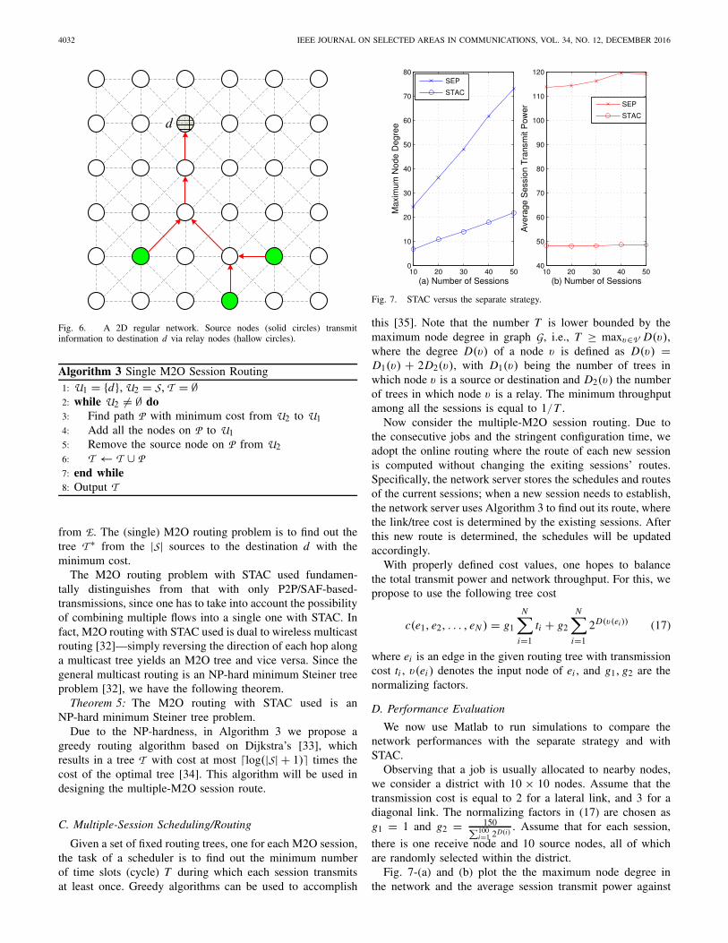
Fig. 6. A 2D regular network. Source nodes (solid circles) transmitinformation to destination d via relay nodes (hallow circles).
Algorithm 3 Single M2O Session Routing1: U1 = {d}, U2 = S, T = ∅2: while U2 �= ∅ do3: Find path P with minimum cost from U2 to U14: Add all the nodes on P to U15: Remove the source node on P from U26: T ← T ∪ P7: end while8: Output T
from E. The (single) M2O routing problem is to find out thetree T ∗ from the |S| sources to the destination d with theminimum cost.
The M2O routing problem with STAC used fundamen-tally distinguishes from that with only P2P/SAF-based-transmissions, since one has to take into account the possibilityof combining multiple flows into a single one with STAC. Infact, M2O routing with STAC used is dual to wireless multicastrouting [32]—simply reversing the direction of each hop alonga multicast tree yields an M2O tree and vice versa. Since thegeneral multicast routing is an NP-hard minimum Steiner treeproblem [32], we have the following theorem.
Theorem 5: The M2O routing with STAC used is anNP-hard minimum Steiner tree problem.
Due to the NP-hardness, in Algorithm 3 we propose agreedy routing algorithm based on Dijkstra’s [33], whichresults in a tree T with cost at most �log(|S| + 1)� times thecost of the optimal tree [34]. This algorithm will be used indesigning the multiple-M2O session route.
C. Multiple-Session Scheduling/Routing
Given a set of fixed routing trees, one for each M2O session,the task of a scheduler is to find out the minimum numberof time slots (cycle) T during which each session transmitsat least once. Greedy algorithms can be used to accomplish
Fig. 7. STAC versus the separate strategy.
this [35]. Note that the number T is lower bounded by themaximum node degree in graph G, i.e., T ≥ maxv∈V D(v),where the degree D(v) of a node v is defined as D(v) =D1(v) + 2D2(v), with D1(v) being the number of trees inwhich node v is a source or destination and D2(v) the numberof trees in which node v is a relay. The minimum throughputamong all the sessions is equal to 1/T .
Now consider the multiple-M2O session routing. Due tothe consecutive jobs and the stringent configuration time, weadopt the online routing where the route of each new sessionis computed without changing the exiting sessions’ routes.Specifically, the network server stores the schedules and routesof the current sessions; when a new session needs to establish,the network server uses Algorithm 3 to find out its route, wherethe link/tree cost is determined by the existing sessions. Afterthis new route is determined, the schedules will be updatedaccordingly.
With properly defined cost values, one hopes to balancethe total transmit power and network throughput. For this, wepropose to use the following tree cost
c(e1, e2, . . . , eN ) = g1
N∑
i=1
ti + g2
N∑
i=1
2D(v(ei)) (17)
where ei is an edge in the given routing tree with transmissioncost ti , v(ei ) denotes the input node of ei , and g1, g2 are thenormalizing factors.
D. Performance Evaluation
We now use Matlab to run simulations to compare thenetwork performances with the separate strategy and withSTAC.
Observing that a job is usually allocated to nearby nodes,we consider a district with 10 × 10 nodes. Assume that thetransmission cost is equal to 2 for a lateral link, and 3 for adiagonal link. The normalizing factors in (17) are chosen asg1 = 1 and g2 = 150∑100
i=1 2D(i). Assume that for each session,
there is one receive node and 10 source nodes, all of whichare randomly selected within the district.
Fig. 7-(a) and (b) plot the the maximum node degree inthe network and the average session transmit power against

WU et al.: STAC IN WIRELESS DCNs 4033
Fig. 8. Minimum session rate comparison.
the number of sessions, respectively. As can be seen, themaximum node degree, whose reciprocal upper bounds theminimum session throughput, increases linearly with the ses-sion number for both strategies, but the slope for the separatestrategy is much larger than that for STAC; while the averagesession transmit power is roughly independent of the sessionnumber, and that for the separate strategy is about three timesof that for STAC. A comparison of the minimum sessionthroughput is given Fig. 8.
VI. CONCLUSION
The wireless DCN differs from general wireless networksin that it has large amounts of M2O sessions, which arenormally followed by further computations at the destinations,with weighted summation being the typical case. Building onthis observation and several distinguishing characteristics ofDCs like limited and controlled physical space with staticchannels, we have proposed a novel physical layer schemeSTAC that achieves simultaneous transmissions and compu-tations over the air, and an enhanced SDN architecture toenable it. We showed that STAC can significantly improveboth bandwidth and energy efficiencies. STAC also opens anumber of exciting future research directions:
A. Effect on MapReduce Algorithms
Since STAC inherently integrates transmissions and compu-tations, its application can impact the design of computationalgorithms in MapReduce. For instance, if the desired compu-tation at the reduce node is in a product form: s0 = ∏K
i=1 si ,then to apply STAC, one can make a log operation on the mapnode’s output: s′i = ln si , so that the reduce node can easilytransform its received s′0 =
∑Ki=1 s′i to s0 by taking s0 = es ′0 .
B. Advanced Transmission Techniques
This paper only focuses on introducing the basic idea ofSTAC, while it is possible to combine STAC with other
advanced techniques. For example, observing the broadcasttraffic [36] in DCs, one can consider exploiting the broad-cast nature of wireless medium when designing transmissionschemes.
We can also enable inter-session packet scrambling withthe idea of network coding [37]. By allowing inter-sessionnetwork coding, especially physical-layer network coding forthe bi-directional traffic [38], the system performance can befurther improved.
Additionally, although this paper assumes no error correc-tion coding for simplicity, channel coding can be indeed usedin STAC to combat the noise. Linear channel codes as in (1)are directly applicable, and new channel decoding schemescan be devised as in [39].
C. Theoretical Challenges
STAC brings new challenges to both communication andnetworking theories. For the one-hop communication model,the capacity and the trade-off between bandwidth and energyefficiencies need further investigations; for the multi-hopmulti-session networking model, it would be of interest to findeffective polynomial time routing algorithms for some specialedge costs.
REFERENCES
[1] S. Zhang, X. Wu, and A. Ozgur, “STAC: Simultaneous transmitting andair computing in wireless data center networks,” in Proc. IEEE/CIC Int.Conf. Commun. China (ICCC), Nov. 2015, pp. 1–7.
[2] S. Kandula, J. Padhye, and P. Bahl, “Flyways to de-congest data centernetworks,” in Proc. ACM HotNets Conf., 2009, pp. 1–6.
[3] K. Ramachandran, R. Kokku, R. Mahindra, and S. Rangarajan, “60 Ghzdata-center networking: Wireless ⇒ worryless?” NEC Lab. Amer. Inc.,Princeton, NJ, USA, Tech. Rep., Jul. 2008, pp. 1–11.
[4] X. Zhou et al., “Mirror mirror on the ceiling: Flexible wireless links fordata centers,” in Proc. ACM SIGCOMM Conf., New York, NY, USA,2012, pp. 443–454.
[5] N. Hamedazimi et al., “Firefly: A reconfigurable wireless data cen-ter fabric using free-space optics,” in Proc. ACM SIGCOMM Conf.,New York, NY, USA, 2014, pp. 319–330.
[6] D. Halperin, S. Kandula, J. Padhye, P. Bahl, and D. Wetherall, “Aug-menting data center networks with multi-gigabit wireless links,” in Proc.ACM SIGCOMM Conf., New York, NY, USA, 2011, pp. 38–49.
[7] J.-Y. Shin, E. G. Sirer, H. Weatherspoon, and D. Kirovski, “On thefeasibility of completely wirelesss datacenters,” IEEE/ACM Trans. Netw.,vol. 21, no. 5, pp. 1666–1679, Oct. 2013.
[8] Y. Cui, H. Wang, X. Cheng, and B. Chen, “Wireless data center net-working,” IEEE Wireless Commun., vol. 18, no. 6, pp. 46–53, Dec. 2011.
[9] Y. Cui, H. Wang, and X. Cheng, “Channel allocation in wireless datacenter networks,” in Proc. IEEE INFOCOM, Apr. 2011, pp. 1395–1403.
[10] S. Ghemawat, H. Gobioff, and S.-T. Leung, “The Google file system,”in Proc. 19th ACM Symp. Oper. Syst. Principles (SOSP), New York, NY,USA, 2003, pp. 29–43.
[11] J. Dean and S. Ghemawat, “MapReduce: Simplified data processingon large clusters,” Commun. ACM, vol. 51, no. 1, pp. 107–113,2008.
[12] L. Mucchi, L. Ronga, and G. Chisci, “Noise-loop multiple access,” IEEETrans. Veh. Technol., to be published.
[13] R. Liu, “Autocorrelation division multiple access systems (ADMA),” inProc. Int. Conf. Commun., Circuits Syst., Jul. 2009, p. 1.
[14] A. G. Dimakis, P. B. Godfrey, Y. Wu, M. J. Wainwright, andK. Ramchandran, “Network coding for distributed storage systems,”IEEE Trans. Inf. Theory, vol. 56, no. 9, pp. 4539–4551, Sep. 2010.
[15] C.-T. Chu et al., “MapReduce for machine learning on multicore,” inProc. Neural Inf. Process. Syst. Conf. (NIPS), Apr. 2006, p. 281.
[16] C. Shepard et al., “Argos: Practical many-antenna base stations,” in Proc.18th Annu. Int. Conf. Mobile Comput. Netw. (MobiCom), New York, NY,USA, 2012, pp. 53–64.

4034 IEEE JOURNAL ON SELECTED AREAS IN COMMUNICATIONS, VOL. 34, NO. 12, DECEMBER 2016
[17] N. McKeown et al., “OpenFlow: Enabling innovation in campus net-works,” ACM SIGCOMM Comput. Commun. Rev., vol. 38, no. 2,pp. 69–74, Apr. 2008.
[18] K. Shvachko, H. Kuang, S. Radia, and R. Chansler, “The hadoopdistributed file system,” in Proc. IEEE 26th Symp. Mass Storage Syst.Technol. (MSST), May 2010, pp. 1–10.
[19] Y. Wu, “Existence and construction of capacity-achieving network codesfor distributed storage,” IEEE J. Sel. Areas Commun., vol. 28, no. 2,pp. 277–288, Feb. 2010.
[20] D. S. Papailiopoulos, J. Luo, A. G. Dimakis, C. Huang, and J. Li,“Simple regenerating codes: Network coding for cloud storage,” in Proc.IEEE INFOCOM, Mar. 2012, pp. 2801–2805.
[21] C. Ranger, R. Raghuraman, A. Penmetsa, G. Bradski, and C. Kozyrakis,“Evaluating mapreduce for multi-core and multiprocessor systems,” inProc. 13th IEEE Int. Symp. High Perform. Comput. Archit. (HPCA),Feb. 2007, pp. 13–24.
[22] S. Seo, E. J. Yoon, J. Kim, S. Jin, J.-S. Kim, and S. Maeng, “HAMA:An efficient matrix computation with the mapreduce framework,” inProc. IEEE 2nd Int. Conf. Cloud Comput. Technol. Sci. (CloudCom),Nov./Dec. 2010, pp. 721–726.
[23] C. Liu, H. Yang, J. Fan, L.-W. He, and Y.-M. Wang, “Distributednonnegative matrix factorization for web-scale dyadic data analysis onmapreduce,” in Proc. 19th Int. Conf. World Wide Web, New York, NY,USA, 2010, pp. 681–690.
[24] T. Elsayed, J. Lin, and D. W. Oard, “Pairwise document similarity inlarge collections with MapReduce,” in Proc. 46th Annu. Meeting Assoc.Comput. Linguistics Human Lang. Technol., Short Papers, Stroudsburg,PA, USA, 2008, pp. 265–268.
[25] S. Zhang, S. C. Liew, and P. P. Lam, “Hot topic: Physical-layer networkcoding,” in Proc. 12th Annu. Int. Conf. Mobile Comput. Netw., 2006,pp. 358–365.
[26] E. E. Marinelli, “Hyrax: Cloud computing on mobile devices usingmapreduce,” M.S. thesis, Carnegie Mellon Univ., Pittsburgh, PA, USA,2009.
[27] J. Yick, B. Mukherjee, and D. Ghosal, “Wireless sensor network survey,”Comput. Netw., vol. 52, no. 12, pp. 2292–2330, Aug. 2008.
[28] R. Mudumbai, G. Barriac, and U. Madhow, “On the feasibility ofdistributed beamforming in wireless networks,” IEEE Trans. WirelessCommun., vol. 6, no. 5, pp. 1754–1763, May 2007.
[29] D. R. Brown, III, and H. V. Poor, “Time-slotted round-trip carrier syn-chronization for distributed beamforming,” IEEE Trans. Signal Process.,vol. 56, no. 11, pp. 5630–5643, Nov. 2008.
[30] W. Braun and M. Menth, “Software-defined networking using open-flow: Protocols, applications and architectural design choices,” FutureInternet, vol. 6, no. 2, pp. 302–336, 2014.
[31] D. Cox, E. Jovanov, and A. Milenkovic, “Time synchronization forZigBee networks,” in Proc. 37th Southeastern Symp. Syst.Theory (SSST), Mar. 2005, pp. 135–138.
[32] J. E. Wieselthier, G. D. Nguyen, and A. Ephremides, “On the con-struction of energy-efficient broadcast and multicast trees in wirelessnetworks,” in Proc. 19th Annu. Joint Conf. IEEE Comput. Commun.Soc. (INFOCOM), vol. 2. Mar. 2000, pp. 585–594.
[33] E. W. Dijkstra, “A note on two problems in connexion with graphs,”Numer. Math., vol. 1, no. 1, pp. 269–271, Dec. 1959.
[34] A. Goel and K. Munagala, “Extending greedy multicast routing todelay sensitive applications,” Algorithmica, vol. 33, no. 3, pp. 335–352,Jul. 2002.
[35] F. Gavril, “Algorithms for minimum coloring, maximum clique, mini-mum covering by cliques, and maximum independent set of a chordalgraph,” SIAM J. Comput., vol. 1, no. 2, pp. 180–187, 1972.
[36] S. Kandula, S. Sengupta, A. Greenberg, P. Patel, and R. Chaiken, “Thenature of data center traffic: Measurements & analysis,” in Proc. 9thACM SIGCOMM Conf. Internet Meas. Conf., New York, NY, USA,2009, pp. 202–208.
[37] R. Ahlswede, N. Cai, S.-Y. R. Li, and R. W. Yeung, “Network infor-mation flow,” IEEE Trans. Inf. Theory, vol. 46, no. 4, pp. 1204–1216,Jul. 2000.
[38] M. Al-Fares, S. Radhakrishnan, B. Raghavan, N. Huang, and A. Vahdat,“Hedera: Dynamic flow scheduling for data center networks,” in Proc.7th USENIX Conf. Netw. Syst. Design Implement., Berkeley, CA, USA,2010, p. 19.
[39] S. Zhang and S.-C. Liew, “Channel coding and decoding in a relaysystem operated with physical-layer network coding,” IEEE J. Sel. AreasCommun., vol. 27, no. 5, pp. 788–796, Jun. 2009.
Xiugang Wu (S’08–M’15) received theB.Eng. degree (Hons.) in electronics andinformation engineering from Tongji University,Shanghai, China, in 2007, and the M.A.Sc. andPh.D. degrees in electrical and computer engineeringfrom the University of Waterloo, Waterloo, ON,Canada, in 2009 and 2014, respectively.
He is currently a Post-Doctoral Research Fellowwith the Department of Electrical Engineering,Stanford University, Stanford, CA, USA. Hisresearch interests include information theory and
wireless networks.
Shengli Zhang (M’10) received the B.Eng. degreein electronic engineering and the M.Eng. degree incommunication and information engineering fromthe University of Science and Technology of China(USTC), Hefei, China, in 2002 and 2005, respec-tively, and the Ph.D. degree from the Departmentof Information Engineering, The Chinese Univer-sity University of Hong Kong (CUHK), in 2008.From 2002 to 2005, he was with the PersonalCommunication Network and Spread Spectrum Lab-oratory, USTC, as a Research Engineer, where
he was involved in several National 863 research projects including theBeyond-3 Generation of Mobile System in China (FUTURE Plan). From2002 to 2005, he was also a Research Engineer with the UTStarcom WirelessSoft Research Center, Hefei, where he was involved in the research andimplementation of the WCDMA communication systems. From 2008, he wasa Research Associate with CUHK. He is currently an Associate Professor withthe Communication Engineering Department, Shenzhen University, China. Hiscurrent research interests include wireless networks, wireless communication,physical layer network coding, and cooperative wireless networks.
Ayfer Özgür (M’06) received the B.Sc. degreein electrical engineering and physics and theM.Sc. degree in communications from Middle EastTechnical University, Turkey, in 2001 and 2004,respectively, and the Ph.D. degree from theInformation Processing Group, EPFL, Switzerland,in 2009. From 2001 to 2004, she was a HardwareEngineer with the Defense Industries DevelopmentInstitute, Turkey. From 2010 to 2011, she was a Post-Doctoral Scholar with the Algorithmic Research inNetwork Information Group, EPFL. She is currently
an Assistant Professor with the Electrical Engineering Department, StanfordUniversity. Her research interests include network communications, wirelesssystems, and information and coding theory. She received the EPFL BestPh.D. Thesis Award in 2010 and the NSF CAREER Award in 2013.