4006080-02 gv60cko outdoor kit installation e-f - valor · outdoor fireplace installed in...
TRANSCRIPT

4006080-02
GV60CKO
DO NOT USE thermostatic handset supplied with appliance when installing outdoors!
U S E 1 2 6 5 W S K o r R B W S K ( a p p l i a n c e i n s t a l l e d u n d e r o v e r h a n g )
FIREPL ACE
BAT TERY
ACCESS
UP
ON-OFF
DOWN
ACCÈS
PILES
DU FOYERX X© Copyright Miles Industries Ltd., 2017.
GV60 Outdoor Fireplace Conversion Kit
Installation Instructions
Use with with Valor Models 530 (ZC only), 534, 650, 1100, 1150, 1400, 1500, 1600, 1700, 1800 Heaters ONLY
WARNINGThis conversion kit shall be installed by a qualifi ed service agency in accordance with the manufacturer’s instructions and all applicable codes and requirements of the authority having jurisdiction. If the information in these instructions is not followed exactly, a fi re, explosion or pro-duction of carbon monoxide may result causing property damage, personal injury or loss of life. The qualifi ed service agency is responsible for the proper installation of this kit. The installation is not proper and complete until the operation of the con-verted appliance is checked as specifi ed in the manufacturer’s instructions supplied with the kit.Use this manual in conjunction with the in-stallation manual supplied with the appliance.
LEAVE THIS MANUAL WITH THE HOMEOWNER.
WARNINGElectrical shock hazard - Do not install elec-trical accessories (fans and lighting) when converting the appliance for use outdoors.
!
!
General notes regarding conversionThis manual contains instructions for adapting natural gas or propane models listed above for use outdoors. For the purpose of this manual the term “outdoor” means installed outside of the insulated building envelope within a weatherproof enclosure having a minimum required overhang. The outdoor space may be attached or free standing to the main/primary structure and may or may not include walls. See page 6 for further information regarding locating your outdoor fi replace.Use this manual in conjunction with the installation manual supplied with the appliance. The outdoor fi replace must be permanently situated and connected to a fi xed piping system and must not be portable.
Notes• No electrical accessories (fans or lighting) permitted
when adapting the appliance for outdoor use.• Any of the optional available trims and fronts may
be used in the outdoor environment including optional HeatShift components although please note that some fading or corrosion may occur due to environmental conditions. Cast iron fronts are not recommended outdoors.
• Thermostatic controls are not allowed for outdoor fi replaces. Use the wall switch supplied with the appliance or when not supplied, order an optional RBWSK Remote battery and wall switch kit to control the appliance. Do not use the thermostatic remote controled handset supplied with the appliance!
1265WSK–Wall Switch
RBWSK–Remote Batteries & Wall Switch Kit

2
CAUTIONDO NOT USE a screwdriver or other metallic object to remove the batteries from the receiver or the handset! This could cause a short circuit to the receiver.
CAUTIONTo avoid short-circuit to the receiver, position the antenna so that it DOES NOT TOUCH the ignition wire.
Ignition Wire Connection (spade type connector)
Be careful when removing and reinstallaing: not to bend or
break the spade connector
Ignition Wire
Antenna
Replace the existing receiverLocate the existing receiver on the appliance. The receiver is held in place by Velcro on most appliances. Refer to the appliance’s manual if necessary.
1. Detach the receiver and pull it out of the appliance to disconnect it. Be careful not to pull too hard as you could damage the wire connections, particularly the ignition wire connection.
2. Remove all the wires connected to the receiver and set the receiver aside.
3. Connect the outdoor receiver (G6R-R3AMC) to the existing wiring. DO NOT INSTALL BATTERIES YET! Ensure no batteries are installed in the RBWSK if used. Connections on the outdoor receiver are identical to the existing receiver. See diagram below.
Valve Wire Harness
Red
Yellow
Wall Switch Harness
RBWSK— Remote Battery Wall Switch kit power connector
IMPORTANT: The connection can only be done one way. Do not force it or damage the pins on the receiver box!
4. Install and connect the wall switch supplied with the appliance to the receiver following instructions provided with the appliance’s installation manual; if the appliance is not supplied with a wall switch, connect the RBWSK—Remote battery and wall switch kit (supplied separately) to the outdoor receiver—see installation instructions supplied with the kit.
5. Insert 4 AA alkaline batteries into the outdoor receiver or the RBWSK kit only after all connections are completed.
6. Test the operation of the wall switch—see appliance’s or wall switch kit instructions manual.
CAUTIONDO NOT PUT BATTERIES IN THE REMOTE CONTROL RECEIVER OR RBWSK until the wires are connected to the burner control unit as short-circuit could result in the destruction of the electrical components.Take the switch wire and plug it into the receiver’s connection slot as indicated.
Kit Contents1 GV60 outdoor receiver with conformal coating—
to resist weather—part no. 40051111 Overlay conversion label—part no. 40060811 Outdoor Lighting Instructions card—part no. 4005169
G6R-R3AMC—Outdoor receiver
Conversion label and Lighting Instructions

3
CAUTIONBe careful when using a hose or pressure washing to clean the areas around the fi replace. NEVER SPRAY WATER DIRECTLY AT THE FIREPLACE!
Cleaning AROUND Your Fireplace
Your Valor outdoor gas fi replace will tolerate moderate amounts of water on an occasional basis but is not designed to be waterproof.
Ensure the fi replace is turned off - including pilot - before performing any cleaning around it. Use plastic sheeting to protect the fi replace front and trim from direct spray while cleaning. Ensure all plastic is removed before operating fi replace.
Exposure to outdoor UV lightExposure to outdoor UV light will cause some plated and painted fi nishes to fade over time. This fading is unavoidable and not covered under warranty. To minimize fading, locate the fi replace away from direct sunlight. Decommissioning and covering the fi replace over the off -season will also prolong the fi nish.
Decommission During Off -SeasonWe recommend decommissioning your outdoor fi replace during the off -season when it will not be used for an extended period. Decommission your fi replace by removing the batteries from the battery holder and turning the gas shut-off valve to the “off ” position.Upon ensuring the fi replace cannot be turned on you can then apply a weather protective cover over the front of the fi replace to help preserve the fi nish and further protect the appliance from weather.Note: Do not operate your outdoor fi replace during cold weather below freezing point (32°F, 0°C).
Fix the conversion label and replace the lighting instructionsThe data label and lighting information cards are located either under the fi rebox near the gas valve or on the right side of the fi rebox. They are retained to the appliance by a wire.
Data label and lighting instructions located near the gas valve or to the right of fi rebox
1. Fix the conversion label on the data card as indicated.
2. Remove the existing lighting instructions by cutting the card out near its fi xing point.
3. Staple the new lighting instructions to the data card near its fi xing point.
4. Place back in appliance.
fi replace data card
lighting instructions
conversion label
Supplementary Owner’s Information

4
Lighting Instructions for Outdoor Fireplace Use
FOR YOUR SAFETY, READ BEFORE LIGHTINGWARNING: If you do not follow these instructions exactly, a fi re or explosion may result causing property damage, personal injury or loss of life.A. This appliance has a pilot which must be lighted by hand or wall switch. Follow these instructions exactly. To
save gas, turn the pilot off when not using the appliance for a prolonged period of time.B. BEFORE LIGHTING, smell all around the appliance area for gas. Be sure to smell next to the fl oor because
some gases are heavier than air and will settle on the fl oor.WHAT TO DO IF YOU SMELL GAS• Do not try to light any appliance.• Do not touch any electric switch; do not use any phone in your building.• Immediately call your gas supplier from a neighbor’s phone. Follow the gas supplier’s instructions.• If you cannot reach your gas supplier, call the fi re department.
C. Use only your hand to push in or turn the control knobs. Never use tools. If the knobs will not push in or turn by hand, don’t try to repair them; call a qualifi ed service technician. Force or attempted repair may result in a fi re or explosion.
D. Do not use this appliance if any part has been under water. Immediately call a qualifi ed service technician to inspect the appliance and to replace any part of the control system and any gas control, which has been under water.
LIGHTING INSTRUCTIONS1. STOP! Read the safety information above.2. TO CLEAR ANY GAS, turn main valve off by pressing ON/OFF on wall switch (1).
• Wait fi ve (5) minutes to clear out any gas, then smell for gas, including near the fl oor. If you smell gas, STOP! Follow “B” in the safety information above on this label. If you don’t smell gas, go to the next step.
3. AUTOMATIC IGNITION: MAN-knob (2) in ON position. Ensure Flame Adjustment knob (3) is set to lowest setting () (Fig. 1). Locate the pilot (Fig. 3.) inside of fi rebox at left hand side.
• On the wall switch, press the ON button; a short acoustic signal confi rms the start has begun.
• Further short acoustic signals indicate the ignition process is in progress.• When the pilot is lit, the Flame Adjustment knob (3) will automatically rotate to
the highest setting.• Press the small fl ame button () on the wall switch to reduce the fl ame height.
4. MANUAL IGNITION: MAN-knob (2) in MAN position (Fig. 2). With the window off , locate the pilot (Fig. 3) inside of fi rebox at left hand side.
• Set Flame Adjustment knob (3) to the lowest setting ().• Push down the metallic core (4) with a pen or similar instrument; this will establish
the pilot gas fl ow.• Light gas at the pilot (5) with a match.• Continue holding down metal core (4) for about 10 seconds; after release, pilot
should remain lit.• If the pilot will not stay lit after several tries, turn the gas control knob (3) to OFF
() and call your local service technician or gas supplier.• Reinstall the window and set the MAN-knob (2) to ON; turn Flame Adjustment knob (3) up () or down ()
manually or use the fl ame buttons ()() buttons on the wall switch to adjust the fl ame height.
TO TURN OFF GAS TO APPLIANCEAUTOMATIC SHUT-OFF (using the wall switch):
• Press and hold the small fl ame button () on the wall switch to shut-off the main burner gas fl ow.• Press ON/OFF button on wall switch to shut-off the appliance, including pilot fl ame.
Spark
PilotFig 3
5
Fig 1
Fig 2
1OFF

5
Min. required weatherproof overhang in front and at sides of
fireplace is 1/2 of the heightof the overhang measured
from the base of the unit
1265WSK Wall switch orRBWSK Remote battery
& wall switch kit must be located within
weather protected area
Min. requiredoverhang
Vertical terminationrecommended toavoid flue productsfrom accumulatingin outdoor spaces
See appliancemanual andpage 12 ofthis manual forallowable ventterminal locations
Min. requiredoverhang
Outdoor fireplace installed in weatherproof enclosure
1
2
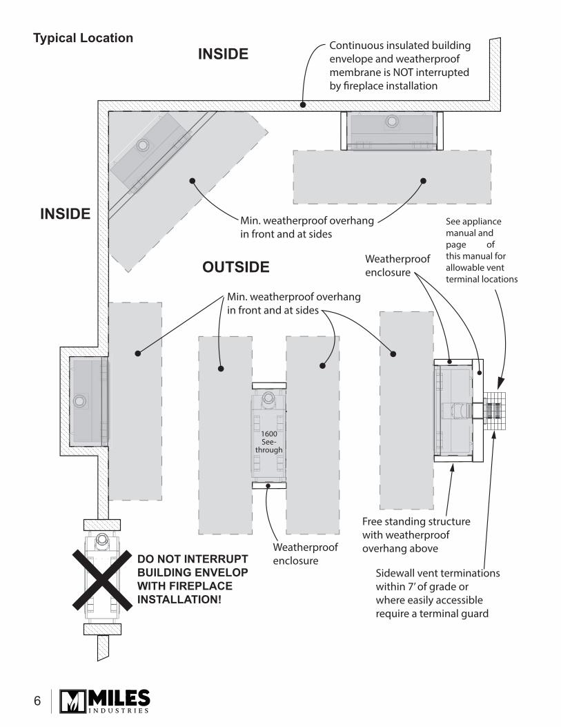
LocationFor the purposes of this installation manual the term “outdoor” means installed outside of the insulated building envelope within a weatherproof enclosure having a minimum required overhang. The outdoor space may be attached or free standing to the main/primary structure and may or may not include walls. Note: The fi replace will not perform as an exterior wall. If installed against an exterior wall we recommend the appliance enclosure or chase be constructed completely outside of the insultated building envelope and weather membrane.
The fi replace must be permanently situated and connected to a fi xed piping system, it is not portable.
Weather Protection/Moisture ResistanceThis outdoor fi replace will tolerate moderate amounts of water on an occasional basis but is not waterproof.The fi replace must be enclosed in a weatherproof enclosure clad in typical weatherproof material such as siding/stucco/stone/tile, etc. and have a weatherproof structure to shed water that extends horizontally beyond the front and side perimeter of the fi replace (see diagram).Water running down vertical surfaces should be directed away from the fi replace using fl ashings. Measures must be taken to ensure any accumulated water drains away from the fi replace and structure. When the fi replace is installed on surfaces where water may collect or cause damage a suitable drainage pan should be placed under the unit and the water drained away.
Top View (typical)
Side View (typical)
6
Min. weatherproof overhangin front and at sides
Free standing structure with weatherproofoverhang above
Weatherproof enclosure
Weatherproof enclosure
1600See-
through
Continuous insulated buildingenvelope and weatherproofmembrane is NOT interruptedby fireplace installation
INSIDE
INSIDE
OUTSIDE
Min. weatherproof overhangin front and at sides
Sidewall vent terminations within 7’ of grade or where easily accessible require a terminal guard
DO NOT INTERRUPTBUILDING ENVELOPWITH FIREPLACEINSTALLATION!
See appliancemanual andpage ofthis manual forallowable ventterminal locations
Typical Location

7
Combustible Overhang—Left Side ViewLinear Series—1500, 1600, 1700, 1800
0 2” 4” 6” 8” 10” 12”
Bottom of appliance
Face of 1/2” thicknon-combustiblecement board
Do not putfurniture or objectswithin 36” (914 mm)of front of appliance
Min. requiredweatherproofoverhang
CombustibleMantel Projection
(from Face of Cement Board)
CombustibleMantelHeight(from Bottomof appliance)
Fireplace Opening
Combustible Overhang
48” M
in. t
o Co
mbu
stib
le O
verh
ang
(non
-com
bust
ible
con
stru
ctio
n pe
rmite
d lo
wer
)
44”
42”
40”
38”
33”
23-7/8”
9-3/8”
4” minimum to combustible or non-combustible hearth
Note: Use of the optional LDK Duct Kits aff ects mantel and hearth clearances.See instructions packed with LDK Duct Kits.
not to scale

8
Combustible Overhang—Left Side ViewH5 Series—1100, 1150
Bottom of Unit
0 2”1” 4” 6” 8” 10”12”
Do not putfurniture or objectswithin 36” (914 mm)of front of appliance
Mantel Projection(from Face of Cement Board)
MantelHeight(fromBottomof Unit)
49”
47”
45”
43”
41”
4” minimum to combustible floor or hearth. See Hearth Requirementssection of this manual.
Overhang
29”
54” M
in. t
o Co
mbu
stib
le O
verh
ang
(non
-com
bust
ible
con
stru
ctio
n pe
rmite
d lo
wer
)
Min. requiredweatherproofoverhang
Face of 1/2” thicknon-combustiblecement board
Note: Use of the optional LDK Duct Kits aff ects mantel and hearth clearances.See instructions packed with LDK Duct Kits.
not to scale

9
Combustible Overhang—Left Side ViewH6 Series—1400
Bottom of Unit
0 2”1” 4” 6” 8” 10” 12”
Do not putfurniture or objectswithin 36” (914 mm)of front of appliance
MantelHeight(fromBottomof Unit)
52”
50”
48”
46”
34-1/2”
4” minimum to combustible floor or hearth. See Hearth Requirementssection of this manual.
58” M
in. t
o Co
mbu
stib
le C
eilin
g(n
on-c
ombu
stib
le c
onst
ruct
ion
perm
ited
low
er)
Min. requiredweatherproofoverhang
Combustible Overhang
CombustibleMantel Projection
(from Face of Cement Board)
Face of 1/2” thicknon-combustiblecement board
Note: Use of the optional LDK Duct Kits aff ects mantel and hearth clearances.See instructions packed with LDK Duct Kits.
not to scale
10
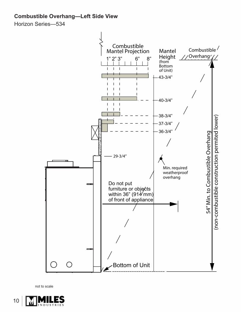
Combustible Overhang—Left Side ViewHorizon Series—534
Bottom of Unit
2”1” 3” 6” 8”
Do not putfurniture or objectswithin 36” (914 mm)of front of appliance
43-3/4”
40-3/4”
38-3/4”
37-3/4”
36-3/4”
29-3/4”
54” M
in. t
o Co
mbu
stib
le O
verh
ang
(non
-com
bust
ible
con
stru
ctio
n pe
rmite
d lo
wer
)
Min. requiredweatherproofoverhang
Combustible Overhang
CombustibleMantel Projection Mantel
Height(fromBottomof Unit)
not to scale

11
Combustible Overhang—Left Side ViewH4 Series—650
Bottom of Unit
4”2” 6” 8”10”12”
38”
36”37”
34”
31-1/4”
35”
29-3/4”
54” M
in. t
o Co
mbu
stib
le O
verh
ang
(non
-com
bust
ible
con
stru
ctio
n pe
rmite
d lo
wer
)
Min. requiredweatherproofoverhang
Combustible Overhang
CombustibleMantel Projection
Do not putfurniture or objectswithin 36” (914 mm)of front of appliance
MantelHeight(fromBottomof Unit)
not to scale

12
Combustible Overhang—Left Side ViewPortrait Series—530 (ZC engine only)
Bottom of Unit
6” 12”10”8”
Do not putfurniture or objectswithin 36” (914 mm)of front of appliance
44”
40”
42”
36”
54” M
in. t
o Co
mbu
stib
le O
verh
ang
(non
-com
bust
ible
con
stru
ctio
n pe
rmite
d lo
wer
)
Min. requiredweatherproofoverhang
Combustible Overhang
CombustibleMantel Projection Mantel
Height(fromBottomof Unit)
not to scale

13
Horizontal Vent Terminal Locations(see appliance manual for allowable vertical terminal locations)
V G
A
Min. 72”Max. 72”
Alcove detail (open on one side) Normal ceiling/soffi t clearances apply.
KEY VENT TERMINAL LOCATIONS - MINIMUM DISTANCES MINIMUM CLEARANCE
Inches CmA Clearance above grade, verandah, porch, deck or balcony 12 30B Clearance to window or door leading to inside space that may be opened 12 30C Clearance to permanently closed window (recommended to prevent condensation on window) 12 30D Vertical clearance to ventilated soffi t located above the terminal within a horizontal distance of 2 feet (60
cm) from the center-line of the terminal 18 46
E Clearance to unventilated soffi t 12 30F Clearance to outside corner 12 30G Clearance to inside corner 12 30H Horizontal clearance to center-line of meter/regulator assembly located within 15 feet (4,6 m) below the
terminal36 90
I Clearance to service regulator vent outlet 36 90J Clearance to non-mechanical air supply inlet to the building or the combustion air inlet to any other
appliance12 30
K Clearance to a mechanical air supply inlet 72 180L Clearance above paved sidewalk or a paved driveway located on public property
Note: A vent must not terminate directly above a sidewalk or paved driveway, which is located between two single-family dwellings and serves both dwellings. THIS DOES NOT APPLY to direct vent, non-condensing appliances in the Province of Ontario.
84 210
M Clearance under a verandah, porch, deck or balcony. Only permitted if veranda, porch, deck or balcony is fully open on a minimum of 2 sides beneath the fl oor
12 30
Note: Local codes and regulations may require diff erent clearances.
• This direct vent appliance is designed to operate when an undisturbed airfl ow hits the outside vent terminal from any direction.
• The minimum clearances from this terminal that must be maintained are shown in the fi gure next page. Any reduc-tion in these clearances could result in a disruption of the airfl ow or a safety hazard. Local codes or regulations may require greater clearances.
• The vent terminal must not be recessed into a wall or siding.
• The vent terminal should be positioned where it will not be covered by snowdrifts.
• Sidewall vent terminations within 7’ of grade or where eas-ily accessible require a terminal guard such as the Valor 658TG or 845TG.
Vent Termination• The vent terminal must be located on a side wall or
through the roof. Where possible, venting through the roof is preferable to sidewall venting to avoid products of combustion from accumulating in outdoor spaces.
• Typically, outdoor spaces are not totally enclosed by solid continuous walls. When sidewall venting is used, the vent terminal will need to be located to avoid products of combustion from accumulating within the outdoor space or from entering the interior space through doors and win-dows. See clearances listed below with respect to open-ings to interior spaces.
• When a sidewall vent terminal terminates below an overhead cover (either permanent or temporary cover) at least 30% of the total perimeter wall area surrounding the outdoor space must be openings.
14
Designed and Manufactured by / forMiles Industries Ltd.
190–2255 Dollarton Highway, North Vancouver, BC, CANADA V7H 3B1Tel. 604-984-3496 Fax 604-984-0246
www.valorfi replaces.com
Because our policy is one of constant development and improvement, details may vary slightly from those given in this publication.
1. Two-Year Parts Warranty Two (2) years from the date of purchase, the Company, at its option, will repair or exchange all parts and components that are found to have a defect in material or workmanship under normal conditions of use.
2. Conditions and LimitationsThe warranty registration card must be completed by the initial owner and returned to the company within 90 days. Alternatively,the warranty registration form may be filled out online at www.valorfireplaces.com Installation and maintenance must be performed by an authorized and trained dealer in accordance with the Company’s installation instructions.This warranty is void where installation of the unit does not conform to all applicable codes including national and local gas
The owner must comply with all operating instructions.The Company is not responsible for the labor costs to remove defective parts or re-install repaired or replacement parts.The initial owner of the unit will be responsible for any shipping charges for replacement parts as well as travel time incurred by the dealer to perform the warranty work.This warranty applies to non-commercial use and service and is void if it is apparent that there is abuse, misuse, alteration, improper installation, accident or lack of maintenance to the unit.This warranty does not cover damage to the unit due to:
i) Improper installation, operational or environmental conditions.ii) Inadequate ventilation in the area or competition for air from other household equipment or appliances.iii) Damage due to chemicals, dampness, condensation, or sulphur in the fuel supply lines which exceeds industry standards.
This warranty does not cover glass, log breakage or damage to the unit while in transit.The Company does not allow anyone to extend, alter or modify this warranty and assumes no responsibility for direct, indirect or
rights extending this warranty and, if so, the Company’s sole obligation under this warranty is to provide labor and/or materials in accordance with those laws.
3. No Other Warrantyy
implied.
a)
b)
c)
d)e)f)
g)
h)
i)j)
Outdoor Installations WarrantyWARRA
NTYPRO
GRAM
WARRANTY
PROGRA
M
VALOR
COM FORT
VALOR
COM FORT
VALOR
COM FORT
If you have a problem with this unit, please contact your dealer or supplier immediately. Under no circumstances should you attempt to service the unit in any way by yourself. The warranties in paragraphs 1 are provided only to the initial owner of this unit, are not transferable and are subject to the conditions and limitations in paragraphs 2, 3. Please review the conditions and limitations carefully and strictly follow their requirements.
Owner sInformation
For Outdoor Installations—This warranty replaces the warranty
supplied with the appliance

15
LE PREMIER FOYER À GAZ RADIANT
MC
®
NE PAS UTILISER la manette de télécommande thermostatique avec le foyer installé à l’extérieur!
UTILISEZ LE 1265WSK ou RBWSK (installé dans un endroit couvert)
GV60 Conversion pour foyer extérieur
Directives d’installation
Utilisez avec les foyers Valor 530 (ZC seulement), 534, 650, 1100, 1150, 1400, 1500, 1600, 1700, 1800 SEULEMENT
Concernant la conversionCe guide contient les directives pour adapter pour usage extérieur les foyers listés ci-dessus, soit au gaz naturel ou au gaz propane. Pour ce guide, le terme “extérieur” désigne un foyer installé à l’extérieur des murs de l’édifi ce dans un espace à l’épreuve des intempéries et couvert d’un surplomb. L’espace extérieur peut être ad-jacent ou séparé de la structure principale de l’édifi ce et peut inclure des murs. Voir page 19 pour plus de rensei-gnements concernant l’emplacement du foyer extérieur.Utilisez ce guide conjointement avec le guide d’installa-tion fourni avec le foyer. Le foyer extérieur doit être situé de façon permanente dans son emplacement et doit être raccordé à un réseau fi xe de tuyaux et ne doit pas être portatif.
Notes• Aucun accessoire électrique (ventilateur ou éclairage)
permis lorsque le foyer est adapté pour l’extérieur.• Toutes bordures ou devantures optionnelles peuvent
être utilisées dans un environnement extérieur; toutefois, veuillez noter que la couleur peut changer et il peut y avoir de la corrosion dus aux conditions climatiques. Les devantures de fonte ne sont pas recommandées à l’extérieur.
• Les commandes thermostatiques ne peuvent pas être utilisées sur les foyers extérieurs. N’utilisez que l’interrupteur mural fourni avec le foyer ou, lorsque non fourni, commandez le Porte-piles et interrupteur mural RBWSK pour contrôler le foyer. NE PAS UTILISER la manette thermostatique de télécommande fournie avec l’appareil.!
FIREPL ACE
BAT TERY
ACCESS
UP
ON-OFF
DOWN
ACCÈS
PILES
DU FOYER
1265WSK–Interrupteur
mural
RBWSK–Porte-piles et
Interrupteur mural
X X
GV60CKO
AVERTISSEMENTCe kit de conversion doit être installé par une agence de service qualifi ée selon les directives du fabricant et tous les codes et règlements applicables dans la juridiction de l’installation. Dans les cas ou les direc-tives de ce guide ne seraient pas suivies à la lettre, un feu, une explosion ou la produc-tion de monoxide de carbone pourraient se produire et causer des dommages matéri-els, des blessures ou la mort. L’agence de service qualifi ée pour eff ectuer cette instal-lation est responsible de l’installation ap-propriée de ce kit. L’installation n’est com-plète que lorsque l’opération de l’appareil converti a été vérifi ée tel qu’indiqué par les directives du fabricant fournies avec ce kit.Utilisez ce guide en conjonction avec le guide d’installation fourni avec le foyer.LAISSEZ CE GUIDE AU CONSOMMATEUR.
AVERTISSEMENTRisque de choc électrique - Ne pas install-er d’accessoires électriques (ventilateur, éclairage) lorsque le foyer est converti pour usage à l’extérieur.
!
!

16
G6R-R3AMC—Récepteur extérieur
Étiquette de conversion et consignes d’allumage
MISE EN GARDEN’UTILISEZ PAS de tournevis ou objet métallique pour enlever les piles du récepteur ou de la manette afi n d’éviter de court-circuiter la télécommande.
MISE EN GARDEAfin d’éviter de court-circuiter le récepteur, placez l’antenne de façon à ce qu’elle NE TOUCHE PAS le fil d’allumage.
Remplacez le récepteur du foyerRepérez le récepteur du foyer. Le récepteur est main-tenu en place par une bande Velcro dans la plupart des foyers. Consultez le guide du foyer si nécessaire.
1. Détachez le récepteur existant et tirez-le hors de l’appareil pour le débrancher. Faites attention de ne pas tirer trop fort afi n de ne pas abîmer les bornes des fi ls, particulièrement celle du fi l d’allumage.
2. Enlevez tous les fi ls branchés au récepteur existant et mettez le récepteur de côté.
3. Branchez le récepteur pour l’extérieur (G6R-R3AMC) aux fi ls existants. N’INSTALLEZ PAS LES PILES POUR LE MOMENT! Assurez-vous qu’aucune pile n’est installée dans le boîtier si le RBWSK est utilisé. Les connexions au récepteur extérieur sont identiques à celles du récepteur original. Voir le schéma ci-dessous.
4. Installez et branchez l’interrupteur mural fourni avec le foyer au nouveau récepteur selon les directives fournies dans le guide d’installation du foyer; si le foyer n’est pas équipé d’un interrupteur mural, bran-chez le Porte-piles et interrupteur mural RBWSK (vendu séparément) au récepteur extérieur—con-sultez les directives d’installation fournies avec le kit.
5. Insérez 4 piles alcalines AA dans le récepteur extérieur ou dans le Porte-piles RBWSK seulement après avoir complété toutes les connexions.
6. Vérifi ez le fonctionnement de l’interrupteur—con-sultez le guide du foyer ou de l’interrupteur mural pour savoir comment fonctionne l’interrupteur.
Connexion du fi l d’allumage (cosse)
Faites attention quand débranchez et rebranchez le fi l d’allumage de ne pas
plier ou briser la cosse
Harnais connexion soupape
Rouge
Jaune
Harnais de connexion Interrupteur mural
Connecteur d’alimentation du Porte-piles et interrupteur mural RBWSK
MISE EN GARDENe placez pas les piles dans le récepteur de la télécommande jusqu’à ce que les fils aient été branchés à la soupape. Un court-circuit pourrait se produire et détruire les composantes électriques.
Contenu du kit1 Récepteur pour l’extérieur GV60 avec
revêtement comforme—résistant aux conditions atmosphériques—pièce no 4005111
1 Étiquette de conversion—pièce no 40060811 Carte de consignes d’allumage pour l’extérieur—
pièce no 4005169
ion du fi l d’allumage(cosse)
n quand débranchez et fi l d’allumage de ne pas
plier ou briser la cosse
n
Rouge
Jaune
Connecteur d’alimentation du Porte-piles et interrupteur mural RBWSK
Antenne
IMPORTANT : Le connecteur ne peut être branché que d’une façon. Ne le forcez pas car il pourrait endommager les fi ches de contact du récepteur!
Branchez le fi l de l’interrupteur dans la borne du récepteur tel qu’indiqué.
Fil d’allumage

17
Nettoyage AUTOUR de votre foyer
Votre foyer extérieur Valor tolérera, à l’occasion, une quantité modérée d’eau mais il n’est pas imperméable ou à l’épreuve de l’eau.Assurez-vous que votre foyer est éteint - incluant la veilleuse - avant de nettoyer autour. Utilisez des toiles de plastiques pour protéger la devanture et bordure du foyer lorsque vous nettoyez. Assurez-vous que toute couverture de plastique est enlevée avant de faire fonctionner votre foyer.
Exposition aux rayons UV à l’extérieurL’exposition aux rayons UV à l’extérieur causera, avec le temps, la décoloration des fi nis peints et plaqués. Cette décoloration est inévitable et n’est pas couverte par la garantie.Pour minimiser la décoloration, situez le foyer à l’écart des rayons directs du soleil. Le fait de mettre le foyer hors service et de le couvrir durant la période ou il n’est pas utilisé prolongera aussi la couleur des fi nitions.Mise hors service pour une période prolongéeNous recommandons de mettre votre foyer extérieur hors service lorsque vous ne l’utiliserez pas pour une période de temps prolongée. Mettez votre foyer hors service en enlevant les piles du récepteur et en tournant le robinet d’arrêt de gaz en position “off ”. En vous assurant bien que le foyer ne peut se rallumer, vous pouvez en couvrir la devanture avec une paroi de protection à l’épreuve des intempéries afi n d’en préserver le fi ni et de protéger l’appareil.Note : Ne pas faire fonctionner le foyer extérieur lorsque la température est au point de congéla-tion ou plus froide (0° C, 32° F).
MISE EN GARDEFaites attention lorsque vous utilisez le nettoyage à pression pour nettoyer autour du foyer.N’ARROSEZ JAMAIS DIRECTEMENT VOTRE FOYER!
Renseignements additionnels pour les consommateurs
Apposez l’étiquette de conversion et remplacez les consignes d’allumageLa carte de spécifi cations et les consignes d’allumage sont situées soit sous la boîte de foyer à côté de la soupape à gaz ou à la droite de la boîte de foyer. Elles sont retenues au foyer par un fi l riveté.
Cartes d’information et consignes d’allumage situées près de la soupape à gaz ou à droite de la boîte de foyer
1. Apposez l’étiquette de conversion sur la carte de d’identifi cation de l’appareil à l’endroit indiqué ci-dessous.
2. Coupez la carte des consignes d’allumage et jetez-la.
3. Brochez la nouvelle carte de consignes d’allumage à la carte d’identifi cation de façon à ce qu’elle puisse être consultée au besoin.
4. Replacez les cartes d’identifi cation et d’allumage dans le foyer.
carte d’identifi -cation du foyer
carte des consignes d’allumage
étiquette deconversion

18
Consignes d’allumage pour foyer utilisé à l’extérieur
Spark
Pilot
POUR VOTRE SÉCURITÉ LIRE AVANT D’ALLUMER
A. Cet appareil possède une veilleuse qui doit être allumée à la main ou avec l’interrupteur mural. Suivez ces instructions à la lettre. Pour économiser l’énergie, éteignez la veilleuse lorsque vous n’utilisez pas l’appareil.
B. AVANT DE FAIRE FONCTIONNER, sentez tout autour de l’appareil pour déceler une odeur de gaz. Sentez près du plancher, car certains gaz sont plus lourds que l’air et peuvent s’accumuler au niveau du sol.QUE FAIRE SI VOUS SENTEZ UNE ODEUR DE GAZ :• Ne pas tenter d’allumer d’appareil.• Ne touchez à aucun interrupteur; ne pas vous servir des téléphones se trouvant dans l’édifi ce.• Appelez immédiatement votre fournisseur de gaz depuis un voisin. Suivez les instructions du fournisseur.• Si vous ne pouvez joindre le fournisseur, appelez le service des incendies.
C. Ne poussez ou ne tournez le bouton d’admission du gaz qu’à la main; ne jamais utiliser d’outil. Si le bouton reste coincé, ne pas tenter de le réparer; appelez un technicien qualifi é. Le fait de forcer le bouton ou de le réparer peut déclencher une explosion ou un incendie.
D. N’utilisez pas cet appareil s’il a été plongé dans l’eau, même partiellement. Faites inspecter l’appareil par un technicien qualifi é et remplacez toute partie du système de contrôle et toute commande qui ont été plongées dans l’eau.
INSTRUCTIONS DE MISE EN MARCHE1. ARRÊTEZ ! Lisez les consignes de sécurité ci-dessus.2. POUR ARRÊTER L’ENTRÉE DE GAZ, éteignez la soupape en pressant sur le bouton
ON/OFF sur l’interrupteur mural (1).• Attendez cinq (5) minutes pour laisser échapper tout le gaz. Vérifi ez autour de l’appareil et près
du plancher s’il y a une odeur de gaz. Si c’est le cas, ARRÊTEZ! Passez à l’étape B des consignes de sécurité ci-dessus. S’il n’y a pas d’odeur de gaz, passez à l’étape suivante.
3. ALLUMAGE AUTOMATIQUE : Bouton MAN à ON (2). Assurez-vous que le bouton de réglage des fl ammes (3) est au réglage le plus bas () (fi g. 1). Repérez la veilleuse (fi g. 3.) à gauche dans la boîte de foyer.
• Sur l’interrupteur mural, appuyez le bouton ON/OFF; un court signal sonore indiquera le début du procédé d’allumage;
• De courts signaux sonores seront entendus jusqu’à ce que le procédé d’allumage soit complet et que le gaz ait circulé dans les tuyaux jusqu’à la soupape;
• Lorsque la veilleuse s’allumera, le bouton d’ajustement des fl ammes (3) tournera automatiquement au réglage le plus haut;
• Appuyez sur le bouton petite fl amme ( ) pour réduire la hauteur des fl ammes.4. ALLUMAGE MANUEL : Bouton MAN à MAN (2) (fi g. 2). Avec la fenêtre enlevée,
repérez la veilleuse (fi g. 3) à gauche dans la boîte de foyer.• Réglez le bouton de réglage des fl ammes (3) à la température la plus basse ();• À l’aide d’un objet pointu comme un stylo, appuyez sur le centre métallique (4) pour
établir l’arrivée du gaz à la veilleuse;• Toujours en appuyant sur le centre métallique (4), allumez le gaz à la veilleuse (5) avec
une allumette;• Continuez d’appuyer sur le centre métallique (4) pour à peu près 10 secondes; relâchez
et la veilleuse restera allumée.• Si la veilleuse s’allume mais ne reste pas allumée après plusieurs essais, tournez le bouton d’alimentation de gaz
(3) à la position “OFF” () et appelez votre agent de service ou votre fournisseur de gaz.• Replacez la fenêtre et mettez le bouton MAN (2) à la position ON; tournez le bouton de réglage des fl ammes (3) vers le
haut () ou le bas () ou utilisez les boutons des fl ammes ( ) ( ) sur l’interrupteur mural pour régler les fl ammes.
COMMENT COUPER L’ADMISSION DE GAZ À L’APPAREILARRÊT AUTOMATIQUE (à l’aide de l’interrupteur mural) :• Appuyez et maintenez le bouton petite fl amme ( ) pour arrêter l’alimentation de gaz;• Appuyez sur le bouton ON/OFF pour fermer la soupape et éteindre la fl amme de la veilleuse.
Fig 3
5
Fig 1
Fig 2
MISE EN GARDE : Quiconque ne respecte pas à la lettre les instructions dans la présente notice risque de déclencher un incendie ou une explosion entraînant des dommages, des blessures ou la mort.
Étincelle
Veilleuse
OFF

19
Vue du dessus typique
Vue de côté typique
Interrupteur mural 1265WSK ou le
Porte-piles et interrupteur mural
RBWSK doit être situé dans un espace à
l’épreuve des intempéries
Sortie verticalerecommendée pouréviter que les produits de combustion évitent de s’accumuler dans les espaces extérieurs
Consultez le guide dufoyer et ce guide à la page 25 pour lesemplacements desortie d’évacuationpermis.
1
2
Surplomb à l’épreuvedes intempéries exigéen avant et de chaque
côté du foyer d’un minimum de 1/2 de lahauteur du surplomb
mesurée à partir de labase de l’appareil
Surplomb minimum exigé
Surplomb minimum exigé
Foyer extérieur installédans un encastrement à l’épreuve des intempéries
EmplacementAux fi ns de ce guide d’installation, le terme “extérieur” désigne l’installation en dehors de l’enveloppe d’isolation d’un édifi ce dans un espace à l’épreuve des intempéries avec un surplomb aux dimensions minimales exigées. L’espace extérieur peut être contigu ou autoportant en rapport à la structure principale et peut inclure des murs ou non. Note : Le foyer ne peut être installé à titre de mur extérieur. Si le foyer est installé contre un mur extérieur, nous conseillons la construction de l’encastrement ou de la charpente complètement en dehors de l’enveloppe du bâtiment et du revêtement d’étanchéité.
Le foyer doit être installé de façon permanente et raccordé à un système de tuyauterie fi xe; il n’est pas portatif.
Protection contre les intempéries / résistance à l’humiditéCe foyer extérieur tolérera à l’occasion une quantité modérée d’eau mais n’est pas imperméable.Le foyer doit être encastré dans une charpente à l’épreuve des intempéries recouverte de matériaux à l’épreuve des intempéries (étanches) tels que parement/stucco/pierre/tuile, etc. et avoir une structure à l’épreuve des intempéries évacuant l’eau et s’étendant horizontalement au-delà du devant et des côtés du foyer (voir schéma).L’eau s’écoulant le long des surfaces verticales devrait être dirigée à l’écart du foyer à l’aide de solins. Des mesures doivent être prises afi n d’assurer que toute accumulation d’eau puisse être drainée à l’écart du foyer et de la structure qui le contient. Lorsque le foyer est installé sur une surface où l’eau peut s’accumuler ou causer des dommages, un bac d’égouttement approprié devrait être placé sous l’appareil et l’eau drainée.

20
1600à 2
faces
INTÉRIEURIN
TÉR
IEU
R
EXTÉRIEUR
NE PAS INTERROMPREL’ENVELOPPE DEL’ÉDIFICE AVEC L’INSTALLATIOND’UN FOYER!
Voir guide du foyer et page 24 de ce guidepour emplacementsde sortie d’évacuationpermis
Structure autoportanteavec surplomb à l’épreuve des intempéries
Encastrementà l’épreuve desintempéries
Encastrementà l’épreuve desintempéries
Enveloppe isolante continue de l’édifice et membrane à l’épreuve des intempéries NE SONT PAS interrompues par l’installation du foyer
Taille minimale du surplomb à l’épreuve des intempéries à l’avant et de chaque côté du foyer
Taille minimale du surplomb à l’épreuve des intempéries à l’avant et de chaque côté du foyer
Les sorties d’évent au mur situées à 7 pieds ou moins d‘un endroit accessible doivent être couvertes par un grillage de protection
Emplacement typique

21
Surplomb combustible—Vu du côté gaucheSéries Linear—1500, 1600, 1700, 1800
0 2” 4” 6” 8” 10” 12”Surplombcombustible
44”
42”
40”
38”
33”
23-7/8”
Bas du foyer
Ne placez aucun meubleou objet à moins de36 po (914 mm) de lafaçade du foyer
Saillie du manteau combustible
(de la surface du panneau de béton)
Hauteurdu manteaucombustible(du bas du foyer)
Ouverturedu foyer
Min
imum
48
po (1
219
mm
) jus
qu’a
u su
rplo
mb
(con
stru
ctio
n in
com
bust
ible
per
mis
e pl
us b
as)
9-3/8 po(238 mm)
Minimum de 4 po (102 mm) jusqu’à la dalle protectrice
Surface du panneau de béton incombustible de 1/2 po (13 mm) d’épaisseur
Surplomb minimum à l’épreuve des intempériesexigé
Saillie ‘A’ du manteau
Hauteur ‘B’ du manteau
1” (25 mm) 33” (838 mm)6” (152 mm) 38” (965 mm)8” (203 mm) 40” (1016 mm)10” (254 mm) 42” (1067 mm)12” (305 mm) 44” (1118 mm)
Note : L’utilisation du Système de canalisation LDK option-nel aff ecte les dégagements aux manteau et dalle protec-trice. Consultez les directives d’installation fournies avec le LDK.
‘A’
‘B’
pas à l’échelle

22
Surplomb combustible—Vu du côté gaucheSérie H5—1100, 1150
0 2”1” 4” 6” 8” 10”12”
49”
47”
45”
43”
41”
Surplomb
29” (737 mm)
Saillie du manteau combustible
(de la surface du panneau de béton)
Hauteurdu manteaucombustible(du bas du foyer)
Bas du foyer
Ne placez aucun meubleou objet à moins de36 po (914 mm) de lafaçade du foyer
Min
imum
54
po (1
372
mm
) jus
qu’a
u su
rplo
mb
(con
stru
ctio
n in
com
bust
ible
per
mis
e pl
us b
as)
Minimum de 4 po (102 mm) jusqu’à la dalle protectrice ou plancher combustible. Voir Exigences relatives au plancher protecteur du guide d’installation du foyer.
Surface du panneau de béton incombustible de 1/2 po (13 mm) d’épaisseur Surplomb
minimum à l’épreuve des intempériesexigé
Profondeur ‘A’ du manteau
Hauteur ‘B’ du manteau
1” (25 mm) 41” (1041 mm)6” (152 mm) 43” (1092 mm)8” (203 mm) 45” (1143 mm)10” (254 mm) 47” (1194 mm)12” (305 mm) 49” (1245 mm)
Note : L’utilisation du Système de canalisation LDK optionnel aff ecte les dégagements aux manteau et dalle protectrice. Con-sultez les directives d’installation fournies avec le LDK.
‘A’
‘B’
pas à l’échelle

23
Surplomb combustible—Vu du côté gaucheSérie H6—1400
0 2”1” 4” 6” 8” 10” 12”
52”
50”
48”
46”
34-1/2” (876 mm)
Surplombcombustible
Saillie du manteau combustible
(de la surface du panneau de béton)
Hauteurdu manteaucombustible(du bas du foyer)
Bas du foyer
Ne placez aucun meubleou objet à moins de36 po (914 mm) de lafaçade du foyer
Min
imum
58
po (1
473
mm
) jus
qu’a
u su
rplo
mb
(con
stru
ctio
n in
com
bust
ible
per
mis
e pl
us b
as)
Minimum de 4 po (102 mm) jusqu’à la dalle protectrice ou plancher combustible. Voir Exigences relatives au plancher protecteur du guide d’installation du foyer.
Surface du panneau de béton incombustible de 1/2 po (13 mm) d’épaisseur Surplomb
minimum à l’épreuve des intempériesexigé
Profondeur ‘A’ du manteau
Hauteur ‘B’ du manteau
1” (25 mm) 46” (1168 mm)8” (203 mm) 48” (1219 mm)10” (254 mm) 50” (1270 mm)12” (305 mm) 52” (1321 mm)
Note : L’utilisation du Système de canalisation LDK optionnel aff ecte les dégagements aux manteau et dalle protectrice. Con-sultez les directives d’installation fournies avec le LDK. ‘A’
‘B’
pas à l’échelle

24
Surplomb combustible—Vu du côté gaucheSérie Horizon—534
2”1” 3” 6” 8”
43-3/4”
40-3/4”
38-3/4”
37-3/4”
36-3/4”
29-3/4” (756 mm)
Surplombcombustible
Saillie du manteau combustible
(de la surface du panneau de béton)
Hauteurdu manteau combustible(du bas du foyer)
Bas du foyer
Ne placez aucun meubleou objet à moins de36 po (914 mm) de lafaçade du foyer
Min
imum
54
po (1
372
mm
) jus
qu’a
u su
rplo
mb
(con
stru
ctio
n in
com
bust
ible
per
mis
e pl
us b
as)
Surplomb minimum à l’épreuve des intempériesexigé
Profondeur ‘A’ du manteau
Hauteur ‘B’ du manteau
1” (25 mm) 36-3/4” (933 mm)2” (51 mm) 37-3/4” (959 mm)3” (76 mm) 38-3/4” (984 mm)6” (152 mm) 40-3/4” (1035 mm)8” (203 mm) 43-3/4” (1111 mm)
‘A’
‘B’
pas à l’échelle

25
Surplomb combustible—Vu du côté gaucheSérie H4—650
4”2” 6” 8”10”12”
38”
36”37”
34”
31-1/4”
35”
29-3/4” (756 mm)
Surplombcombustible
Saillie du manteau combustible Hauteur
du manteau combustible(du bas du foyer)
Bas du foyer
Ne placez aucun meubleou objet à moins de36 po (914 mm) de lafaçade du foyer
Min
imum
54
po (1
372
mm
) jus
qu’a
u su
rplo
mb
(con
stru
ctio
n in
com
bust
ible
per
mis
e pl
us b
as)
Surplomb minimum à l’épreuve des intempériesexigé
Profondeur ‘A’ du manteau
Hauteur ‘B’ du manteau
2” (51 mm) 31-1/4” (794 mm)4” (102 mm) 34” (864 mm)6” (152 mm) 35” (889 mm)8” (203 mm) 36” (914 mm)10” (254 mm) 37” (940 mm)12” (305 mm) 38” (965 mm) ‘A’
‘B’
pas à l’échelle

26
Surplomb combustible—Vu du côté gaucheSérie Portrait—530 (foyer ZC seulement)
6” 12”10”8”
44”
40”
42”
36”
Surplombcombustible
Saillie du manteau combustible (de la surface
du panneau de béton)
Hauteurdu manteau combustible(du bas du foyer)
Bas du foyer
Ne placez aucun meubleou objet à moins de36 po (914 mm) de lafaçade du foyer
Min
imum
54
po (1
372
mm
) jus
qu’a
u su
rplo
mb
(con
stru
ctio
n in
com
bust
ible
per
mis
e pl
us b
as)
Surplomb minimum à l’épreuve des intempériesexigé
Profondeur ‘A’ du manteau
Hauteur ‘B’ du manteau
0–6” (0–152 mm) 36” (914 mm)8” (203 mm) 40” (1016 mm)10” (254 mm) 42” (1069 mm)12” (305 mm) 44” (1118 mm)
‘A’
‘B’
pas à l’échelle

27
Emplacements de la sortie d’évacuation horizontale(consultez le guide du foyer pour l’emplacement de sorties d’évacuation verticales)
EMPLACEMENTS DE SORTIE D’ÉVACUATION—INTERVALLES MINIMUMS DÉGAGE-MENTS MIN.
pouces cm
A Dégagement au-dessus d’une pente, véranda, porche, terrasse surélevée ou hotte 12 30B Dégagement à partir d’une fenêtre ou d’une porte ouvrable donnant sur un espace intérieur 12 30C Dégagement à partir d’une fenêtre non-ouvrable (recommandé afi n d’éviter la condensation sur la fenêtre) 12 30D Dégagement vertical entre un espace ventilé en surplomb (ex. toit) et la sortie d’évacuation, située en-dessous,
sur une largeur de 60 cm (2 pi) de l’axe central de la sortie18 46
E Dégagement à partir d’un espace non-ventilé en surplomb 12 30F Dégagement à partir d’un coin extérieur 12 30G Dégagement à partir d’un coin intérieur 12 30H Dégagement horizontal à partir de l’axe central du compteur/régulateur situé à moins de 15 pieds (4,6 m) sous la
sortie d’évacuation36 90
I Dégagement à partir de la sortie d’air vicié du régulateur 36 90J Dégagement à partir d’une entrée d’air non mécanisée de l’immeuble ou d’une entrée d’air comburant de tout
autre appareil12 30
K Dégagement à partir d’une entrée d’air mécanisée 72 180L Dégagement au-dessus d’un troittoir pavé ou d’une entrée pavée pour véhicules situés sur un lieu public.
Note : Une sortie d’évacuation ne doit pas être installée directement au-dessus d’un trottoir pavé ou d’une entrée pavée pour véhicules situés entre deux résidences familiales pour l’utilisation des deux habitations. CECI NE S’APPLIQUE PAS aux appareils sans condensation, à évent direct, dans la Province de l’Ontario.
84 210
M Dégagement sous une véranda, porche, terrasse surélevée ou balcon. Permis uniquement si la véranda, porche, terrasse surélevée ou balcon est entièrement ouvert sur un minimum de deux côtés sous le plancher.
12 30
Note : Les codes et règlements locaux peuvent exiger des dégagements diff érents.
V G
A
Min. 72”Max. 72”
Détail d’alcove (ouverte sur un côté) Dégagements habituels du plafond/surplomb s’appliquent
au moins 30 % du périmètre total du mur entourant l’espace extérieur doit être ouvert.
• Cet appareil à évent direct est conçu pour fonctionner lorsque la sortie d’évacuation est en contact avec l’air libre de toute perturbation.
• Les dégagements minimum à respecter autour de la sortie d’évacuation sont indiqués ci-dessous. Toute diminution des dégagements pourrait engendrer une perturbation de la circulation d’air ou compromettre la sécurité. Les codes locaux ou règlements peuvent exiger des dégagements plus grands.
• L’extrémité de la sortie d’évacuation doit dépasser le mur ou le revêtement extérieur.
• L’extrémité de la sortie d’évacuation ne doit pas être installée à un endroit susceptible d’être recouvert par un amoncellement de neige.
• La sortie d’évacuation doit être couverte par une grille de protection telle que la Valor 658TG ou la 845TG lorsqu’accessible—à moins de 7 pi (2,13 m) du sol.
Sortie d’évacuation• La sortie d’évacuation doit être située sur un mur ou
sur le toit. Si possible, l’évacuation à travers le toit est préférable à l’évacuation murale afi n d’éviter que les produits de combustion ne s’accumulent dans les espaces extérieurs.
• Typiquement, les espaces extérieurs ne sont pas totalement entourés de murs continus. Lorque l’évacuation se trouve sur un mur de côté, la sortie devra être située de façon à ce que les produits de combustion ne puissent s’accumuler dans l’espace extérieur ou qu’ils ne puissent entrer dans l’espace intérieur par les portes ou fenêtres. Voir les dégage-ments indiqués ci-dessous à l’égard des ouvertures vers l’espace intérieur.
• Lorsqu’une sortie d’évacuation se termine sous une couverture (permanente ou temporaire),

28
Conçue et fabriquée par / pourMiles Industries Ltd.
190–2255 Dollarton Highway, North Vancouver, BC, CANADA V7H 3B1Tél. 604-984-3496 Téléc. 604-984-0246
www.foyervalor.com
Parce que nous favorisons une politique de développement continu, certains détails de la présente publication peuvent varier.
Garantie pour installation à l’extérieurPour Installations extérieures—
Cette garantie remplace la garantie fournie avec le foyer
1. Garantie de deux (2) ans sur les piècesPour une période de deux (2) ans suivant la date d’achat, la Compagnie, à sa discrétion, peut réparer ou échanger toutes pièces ou éléments non indiqués ci-dessus mais qui pourraient être trouvés bona fi de défectueux dû à un défaut de matériau ou de fabrication lorsqu’utilisés dans des conditions normales.
2. Conditions et restrictionsa) La carte d’enregistrement doit être complétée par le propriétaire initial et retournée à la Compagnie dans les 90 jours suivant la date
d’achat. Autrement, le formulaire d’enregistrement de garantie peut être rempli en ligne à www.valorfi replaces.com.b) L’installation et l’entretien doivent être eff ectués par un marchand autorisé et compétent, conformément aux instructions
d’installation de la Compagnie.c) Cette garantie est nulle lorsque l’installation de l’appareil n’est pas faite selon les codes et règlements applicables incluant les codes
nationaux et locaux d’installation d’appareils à gaz de même que les codes de contruction et de prévention d’incendies.d) Le propriétaire doit se conformer aux directives d’opération de l’appareil.e) La Compagnie n’est pas responsable des coûts de main-d’oeuvre pour l’enlèvement de pièces défectueuses ou la réinstallation de
pièces réparées ou remplacées.f) Le propriétaire initial de l’appareil sera responsable des frais d’expédition pour le remplacement de pièces de même que des frais
de déplacement encourus par le réparateur pour eff ectuer une réparation couverte par la garantie.g) Cette garantie s’applique seulement dans les cas d’utilisation non-commerciale et elle est nulle lorsqu’il y a preuve d’abus,
d’altérations, d’installation inappropriée, d’accident ou de défaut d’entretien régulier.h) Cette garantie ne couvre pas les dommages à l’appareil causés par :
i) Installation, opération ou conditions environnementales inappropriées.ii) Évacuation inappropriée ou appareils de la maison se faisant concurrence pour l’air ambiant.iii) Dommages causés par les produits chimiques, l’humidité, la condensation ou le soufre des conduits d’alimentation de gaz
en excès des standards acceptables dans l’industrie.i) Cette garantie ne couvre pas les dommages causés à la vitre ou aux bûches ou à l’appareil lors du transport.j) La Compagnie n’autorise personne, incluant ses distributeurs et marchands, à étendre ou modifi er cette garantie et n’assume
aucune responsabilité pour dommages directs ou indirects causés par cet appareil. Les lois de l’état ou de la province dans laquelle l’acheteur original vit peuvent lui donner des droits particuliers qui étendent cette garantie et, dans ce cas, la seule obligation de la Compagnie sous cette garantie sera de fournir la main-d’oeuvre et/ou les matériaux selon ces lois.
3. Aucune autre garantieL’obligation complète de réparer cet appareil est présentée dans cette garantie. Certains états ou provinces peuvent exiger des garanties additionnelles explicites de la part des fabricants mais, en l’absence de telles exigences explicites de la législation, il n’y a aucune autre garantie expresse ou implicite.
Si vous éprouvez des diffi cultés avec cet appareil, veuillez communiquer immédiatement avec votre marchand ou votre fournisseur. Ne tentez jamais de réparer cet appareil par vous-même. Les garanties énoncées aux paragraphes 1 s’appliquent uniquement au propriétaire initial de cet ap-pareil; elles ne sont pas transférables et sont sujettes aux conditions et restrictions énoncées aux paragraphes 2 et 3. Veuillez vous familiariser avec ces conditions et restrictions et suivez-en strictement les directives.
WARRANTY PROGRAM
WARRANTY PROGRAM
VA
LOR
C O M F ORT
VA
LOR
C O M F ORT
VA
LOR
C O M F ORT