40 lb. portable soda blaster
TRANSCRIPT

40 lb. Portable Soda blaSter
67625
Set uP and oPerating inStructionS
Visit our website at: http://www.harborfreight.com
read this material before using this product. Failure to do so can result in serious injury. SaVe thiS manual.
Copyright© 2009 by Harbor Freight Tools®. All rights reserved. No portion of this manual or any artwork contained herein may be reproduced in any shape or form without the express written consent of Harbor Freight Tools. Diagrams within this manual may not be drawn proportionally. Due to continuing improvements, actual product may differ slightly from the product described herein. Soda Blasters required for assembly and service may not be included.
For technical questions or replacement parts, please call 1-800-444-3353.Revised Manual 10d
SKU 67625 For technical questions, please call 1-800-444-3353. Page 2
SaVe thiS manualKeep this manual for the safety warn-
ings and precautions, assembly, operat-ing, inspection, maintenance and cleaning procedures. Write the product’s serial number in the back of the manual near the assembly diagram (or month and year of purchase if product has no number). Keep this manual and the receipt in a safe and dry place for future reference.
Safety alert Symbol and Signal Words
in this manual, on the labeling, and all other information provid-ed with this product:
this is the safety alert symbol. it is used to alert you to potential personal injury hazards. obey all safety messages that follow this symbol to avoid possible injury or death.
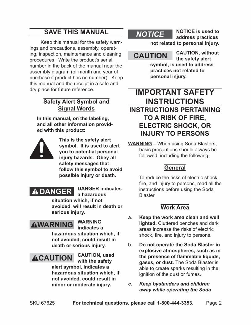
danger indicates a hazardous
situation which, if not avoided, will result in death or serious injury.
Warning indicates a
hazardous situation which, if not avoided, could result in death or serious injury.
caution, used with the safety
alert symbol, indicates a hazardous situation which, if not avoided, could result in minor or moderate injury.
notice is used to address practices
not related to personal injury.
caution, without the safety alert
symbol, is used to address practices not related to personal injury.
imPortant SaFetY inStructionS
inStructionS Pertaining to a riSk oF Fire,
electric Shock, or injurY to PerSonS
Warning – When using Soda Blasters, basic precautions should always be followed, including the following:
generalTo reduce the risks of electric shock, fire, and injury to persons, read all the instructions before using the Soda Blaster.
Work areakeep the work area clean and well a. lighted. Cluttered benches and dark areas increase the risks of electric shock, fire, and injury to persons.
do not operate the Soda blaster in b. explosive atmospheres, such as in the presence of flammable liquids, gases, or dust. The Soda Blaster is able to create sparks resulting in the ignition of the dust or fumes.
Keep bystanders and children c. away while operating the Soda

SKU 67625 For technical questions, please call 1-800-444-3353. Page 3
Blaster. Distractions can result in the loss of control and injury.
Personal SafetyStay alert. Watch what you are do-a. ing and use common sense when operating the Soda Blaster. Do not use the Soda Blaster while tired or under the influence of drugs, al-cohol, or medication. A moment of inattention while operating the Soda Blaster increases the risk of injury to persons.
dress properly. b. Tie up loose sleeves and trouser leggings to prevent con-tact with soda dust.
avoid unintentional starting. be c. sure the media release Valve (18) is off before connecting to the air supply. Do not carry the Soda Blaster with your finger on the Valve or connect the Soda Blaster to the air supply with the Valve on.
do not overreach. keep proper d. footing and balance at all times. Proper footing and balance enables better control of the Soda Blaster in unexpected situations.
e. use safety equipment. A dust mask, non-skid safety shoes and a hard hat must be used for the applicable conditions. Wear heavy-
duty work gloves during use.
f. always wear eye protec-tion. Wear ANSI-ap-proved safety goggles and abrasive blasting hood
(such as SKU 38138).
g. always wear hearing protection when using the Soda blaster. Pro-longed exposure to high intensity noise is able to
cause hearing loss.
Soda blaster use and careUse clamps or another practical a. way to secure and support the work piece to a stable platform. Holding the work by hand or against the body is unstable and is able to lead to loss of control.
do not use the Soda blaster if the b. Valve does not turn the Soda blast-er air supply on or off. Any Soda Blaster that cannot be controlled with the Valve is dangerous and must be repaired.
disconnect the Soda blaster from c. the air source and discharge trapped and air pressure before making any adjustments, changing accessories, or storing the Soda blaster. Such preventive safety mea-sures reduce the risk of starting the Soda Blaster unintentionally. Turn off and detach the air supply, safely discharge any residual air pressure, and turn the Valve to its closed posi-tion before leaving the work area.
Store the Soda Blaster when it is d. idle out of reach of children and other untrained persons. A Soda Blaster is dangerous in the hands of untrained users.
check for misalignment or bind-e. ing of moving parts, breakage of parts, and any other condition that affects the Soda blaster’s operation. If damaged, have the

SKU 67625 For technical questions, please call 1-800-444-3353. Page 4
Soda Blaster serviced before using. Many accidents are caused by poorly maintained Soda Blasters. There is a risk of bursting if the Soda Blaster is damaged.
use only accessories that are f. identified by the manufacturer for this specific Soda Blaster model. Use of an accessory not intended for use with the specific Soda Blaster model, increases the risk of injury to persons.
ServiceSoda Blaster service must be a. performed only by qualified repair personnel who uses only autho-rized and identical replacement parts.
air Sourcea. never connect to an air
source that is capable of exceeding 100 psi. Over pressurizing the Soda Blaster may cause burst-
ing, abnormal operation, failure of the Soda Blaster or serious injury to persons. Use only clean, dry, regu-lated compressed air at the rated pressure or within the rated pressure range as marked on the Soda Blast-er. Always verify prior to using the Soda Blaster that the air source has been adjusted to the rated air pres-sure or within the rated air-pressure range.
Never use oxygen, carbon dioxide, b. combustible gases or any bottled gas as an air source for the Soda Blaster. Such gases are capable of
explosion and serious injury to per-sons.
The warnings and precautions dis-cussed in this manual cannot cover all possible conditions and situations that may occur. It must be under-stood by the operator that common sense and caution are factors which cannot be built into this product, but must be supplied by the operator.
SaVe theSe inStructionS.
SYmbolS and SPeciFic SaFetY
inStructionSSymbol Definitions
Symbol Property or Statement
no No-load speed
.../min Revolutions or reciprocation per minute
PSi Pounds per square inch of pressure
ft-lb Foot-pounds of torque
bPm Blows per minute
cFm Cubic Feet per Minute flow
ScFm Cubic Feet per Minute flow at standard conditions
nPt National pipe thread, tapered
nPS National pipe thread, straight
WARNING marking concerning Risk of Eye Injury. Wear ANSI-approved eye protection.
chart continued in next column.

SKU 67625 For technical questions, please call 1-800-444-3353. Page 5
Symbol DefinitionsSymbol Property or Statement
WARNING marking concerning Risk of Hearing Loss. Wear hearing protection.WARNING marking concerning Risk of Respiratory Injury. Wear NIOSH-approved dust mask/respirator.
WARNING marking concerning Risk of Explosion.
Specific Safety Instructionsdo not use sand (crystalline silica) 1. as a blasting media. See informa-tion on following page regarding the hazards of silica inhalation.
Warning:2. This product, when used for abrasive blasting and similar ap-plications, produces chemicals known to the State of California to cause cancer and birth defects (or other re-productive harm). (California Health & Safety Code § 25249.5, et seq.) Warning: The brass components of this product contain lead, a chemi-cal known to the State of California to cause birth defects (or other repro-ductive harm). (California Health & Safety code § 25249.5, et seq.)
Only use with accessories rated to 3. handle the forces exerted by this Soda Blaster during operation. Other accessories not designed for the forces generated may break and forcefully launch pieces.
Attach all accessories properly to the 4. Soda Blaster before connecting the air supply. A loose accessory may detach or break during operation.
Obey the manual for the air compres-5. sor used to power this Soda Blaster.
Install an in-line shutoff valve to allow 6. immediate control over the air supply in an emergency, even if a hose is ruptured.
Never point the Media Hose Outlet 7. (19) toward yourself or any person or animal. Severe injury may result from the abrasive spray.
Stand back from the item being blast-8. ed. Deflected spray from the abrasive blaster may cause injury.
Prevent overflow or deflected abra-9. sive spray from damaging nearby items. Keep workplace cleared of items which may be damaged by pressurized soda discharge.
All industrial applications of this Soda 10. Blaster must meet OSHA require-ments.
Whenever possible, test the abrasive 11. blaster on a sample or inconspicu-ous part of the work piece to prevent damage during operation.
12. Warning! Abrasive blasting with media con-taining crystalline silica can cause serious or
fatal respiratory disease. Exposure to crystalline silica may cause silico-sis (a serious lung disease), cancer, and death. Exposure to aluminum oxide (a dust generated from material removing processes) can result in eye, skin, and breathing irritation. Always use a NIOSH-approved respirator, safety impact eye glasses, and a full face shield. Avoid skin exposure. Proper ventilation in the work area is required.
Do not use silica sand (or other 13. substances containing more than

SKU 67625 For technical questions, please call 1-800-444-3353. Page 6
1% crystalline silica) as an abrasive blasting material and only use Bicar-bonate of soda media with this Soda Blaster.
Conduct air monitoring to measure 14. worker exposures.
Use containment methods such as 15. blast-cleaning machines and cabinets to control the hazard.
Practice good personal hygiene to avoid 16. unnecessary exposure to silica dust.
Wear washable or disposable protec-17. tive clothes at the work site. Shower, and change into clean clothes before leaving the work site to prevent con-tamination of cars, homes, and other work areas.
Use respiratory protection when source 18. controls cannot keep silica exposures below the recommended levels.
Provide periodic medical examina-19. tions for all workers who may be exposed to crystalline silica.
Post signs to warn workers about 20. the hazard and to inform them about required protective equipment.
Provide workers with training that 21. includes information about health ef-fects, work practices, and protective equipment for crystalline silica.
Report all cases of silicosis to State 22. health departments and to OSHA or the Mine Safety and Health Adminis-tration (MSHA).
SaVe theSe inStructionS.
Functional deScriPtion
Specifications
Operating Air Pressure Range 35-90 PSI
Air Inlet 1/4” -18 NPTAir Consumption @ 90 PSI 8.5 SCFM
Media Capacity 40 lbs.
Media Type Sodium Bicarbonate (Baking Soda)
Air Hose 3/8” (not included)
note: Inline Desiccant Dryer/Filter (SKU 94733) is highly recommended whenever moisture level in
ambient air is high.
initial Soda blaSter Set uP and aSSemblY
read the entire imPortant SaFetY inFormation section at the beginning of this manual including all text under subheadings therein before set up or use of this product.
note: For additional information regarding the parts listed in the following pages, refer to the Assembly Diagram near the end of this manual.
unpackingWhen unpacking, check to make sure
that the item is intact and undamaged. If any parts are missing or broken, please call Harbor Freight Tools at the number shown throughout the manual as soon as possible.
This air Soda Blaster may be • shipped with a protective plug cov-ering the air inlet. Remove this plug before set up.
REV 10d
SKU 67625 For technical questions, please call 1-800-444-3353. Page 7
components and controlsPlease refer to illustrations and parts
list on pages 14-15 to identify important components and controls of this tool.
air Supply to PreVent
exPloSion: use only clean, dry, regulated, compressed air to power this Soda blaster. do not use oxygen, carbon dioxide, combustible gases, or any other bottled gas as a power source for this Soda blaster.
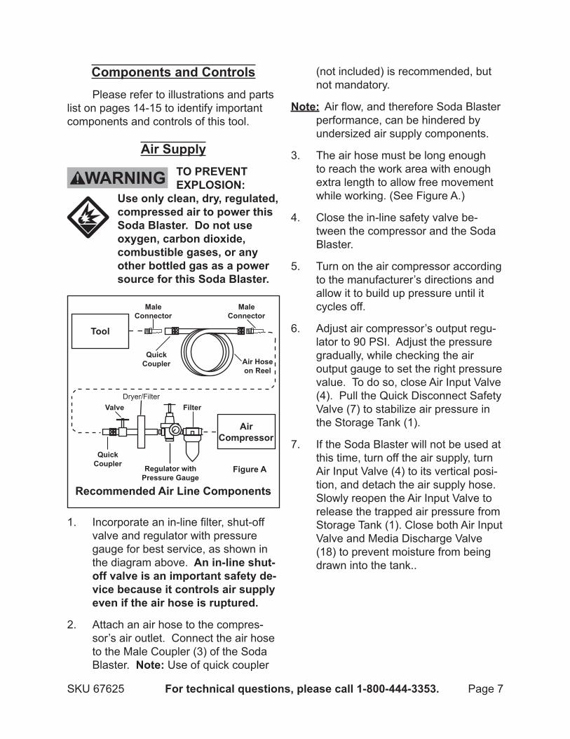
1. Incorporate an in-line filter, shut-off valve and regulator with pressure gauge for best service, as shown in the diagram above. an in-line shut-off valve is an important safety de-vice because it controls air supply even if the air hose is ruptured.
Attach an air hose to the compres-2. sor’s air outlet. Connect the air hose to the Male Coupler (3) of the Soda Blaster. note: Use of quick coupler
(not included) is recommended, but not mandatory.
note: Air flow, and therefore Soda Blaster performance, can be hindered by undersized air supply components.
The air hose must be long enough 3. to reach the work area with enough extra length to allow free movement while working. (See Figure A.)
Close the in-line safety valve be-4. tween the compressor and the Soda Blaster.
Turn on the air compressor according 5. to the manufacturer’s directions and allow it to build up pressure until it cycles off.
Adjust air compressor’s output regu-6. lator to 90 PSI. Adjust the pressure gradually, while checking the air output gauge to set the right pressure value. To do so, close Air Input Valve (4). Pull the Quick Disconnect Safety Valve (7) to stabilize air pressure in the Storage Tank (1).
If the Soda Blaster will not be used at 7. this time, turn off the air supply, turn Air Input Valve (4) to its vertical posi-tion, and detach the air supply hose. Slowly reopen the Air Input Valve to release the trapped air pressure from Storage Tank (1). Close both Air Input Valve and Media Discharge Valve (18) to prevent moisture from being drawn into the tank..
Dryer/Filter
Figure a

SKU 67625 For technical questions, please call 1-800-444-3353. Page 8
oPerating inStructionS read the entire imPortant
SaFetY inFormation section at the beginning of this manual including all text under subheadings therein before set up or use of this product.
inspect Soda blaster before use, looking for damaged, loose, and missing parts. if any problems are found, do not use Soda blaster until repaired.
Soda blaster Set up
note: When setting up this product always use thread sealer tape at every fitting to assure leak free operation.
to PreVent SeriouS injurY
From accidental oPeration: turn off the Soda blaster, detach the air supply, safely discharge any residual air pressure in the Soda blaster, and release the throttle and/or turn the switch to its off position before performing any inspection, maintenance, or cleaning procedures.
to PreVent SeriouS injurY: do not adjust or tamper with any control or component in a way not specifically explained within this manual. improper adjustment can result in Soda blaster failure or other serious hazards.
Ceramic Discharge Nozzle (21)
comPonentS and controlS oF the Portable Soda blaSter
Media Outlet Hose (19)
Storage Tank (1)Nozzle Coupler (20)
Safety Valve (17)
Male Coupler (3)
Air Input Valve (4)
Pressure Gauge (6)
Air Pressure Regulator (5)
Media Regulator (15)
Media Flow Control
Knob (16)
Air Hose (10)
Media Release Valve (18)
Air Pressure Regulator Knob (24)
Quick Release
(14)
Quick Disconnect
Safety Valve (7)
Figure b

SKU 67625 For technical questions, please call 1-800-444-3353. Page 9
attaching the air Pressure regulator assembly
Wrap the threads of the Pressure 1. Gauge (6) with thread sealer tape (not included). Screw the Pressure Gauge into the opening in the face of the Air Pressure Regulator (5). Tight-en snugly using a 9/16” wrench on the back of the gauge block. Rotate till snug but do not overtighten.
Attach Bracket (9) to the Tank us-2. ing the two Socket Head Screws (8) and wrench tighten. Observe the orientation in Figure C., remove the Compression Nut (22) past the Air Pressure Regulator Knob (24) and through the Bracket (9). Align the tab on the Bracket with the recess at gauge side of the regulator, attach compression Nut (22), and finger tighten until snug.
loading media into the tank: Warning! Never service or disas-
semble the Soda Blaster with the air hose attached. Always release any built-up air even after disconnecting the hose.
this portable Soda blaster is de-signed to be used with bicarbon-ate of Soda (baking Soda) as the only media. use of other media may damage this tool.
Applicable Soda Blast Media avail-able from Harbor Freight Tools is 65929 medium grade armex® Soda blast media and 65931 extra large grade armex® Soda blast media.
Make sure the media used is dry to avoid clogging the Media Outlet Hose (19) or Media Regulator (15).
Pull up on the Quick Release Fitting 1. (14) blue ring and pull out Air Hose (10). Hold Bushing (13) with a wrench and Hex Nut on the Bushing with an-other wrench. Remove entire media discharge assembly slowly, being careful with the Pickup Tube (11) as it may contain residual media which can spill when removed. Allow time for the trapped aggregate to safely discharge back into the Storage Tank (1).
Using a funnel, pour up to 40 pounds 2. of media into the Storage Tank. In-spect condition of the O-ring (12) at the bottom of the Bushing (13), and replace if damaged. Insert the Pick up tube into the storage tank, attach the Hex Nut (2) and finger tighten. Tighten the nut (do not over tighten). Pull up on the blue pressure ring and
Bracket (9) Compression Nut (22)
Socket Head Cap Screws (8)
Air Pressure Regulator
Assembly (5)
Figure c
Air Pressure Regulator Knob (24)
Pressure Gauge (6)
Air Filter
Moisture Release Drain Valve
Air Input Valve

SKU 67625 For technical questions, please call 1-800-444-3353. Page 10
insert the tube deep into the fitting. Release the ring (if air leaks around the tube, remove it and cut ap-proximately a quarter of an inch of its length and reattach.
note: 3. If this is a large job, fill the Tank only 3/4 full and reload as needed to finish the job.
imPortant tiP: 4. If the humidity is 90 to 100%, it is recommended to reduce the amount of media and refill more frequently. This will reduce the possibility of clogging the bottom of the Storage Tank (1) and the Media Outlet Hose or Ceramic Discharge Nozzle (21).
Insert the Pickup Tube (11) into the 5. Storage Tank (1).
Place the O-Ring (12) onto the top of 6. the Pickup Tube (11) and position the Media Regulator (15) on top of it.
attaching to air compressor Be sure that the Media Release Valve 1. (18) on top of the Media Regulator (15) is in the OFF (horizontal) posi-tion.
Air Hose (10) should be attached to 2. Air Pressure Regulator outlet and Media Regulator.
Attach the pressure line from the 3. air compressor (not included) to the Regulator.
Open the Air Input Valve (4) (turn to 4. horizontal position) at the air pressure inlet.
Adjust the air pressure to no more 5. than 90 PSI. To do so, lift the Air Pressure Regulator Knob (24) and
turn it clockwise to increase or coun-terclockwise to decrease the air pressure (Read the pressure on the Pressure Gauge). When set, push the knob down to lock the Regulator Knob and save the setting.
Check to be sure all connections are 6. tight with no leaks. Disconnect the air supply and discharge air from the tank before making any needed repairs.
After putting on all required safety 7. equipment, direct the Ceramic Dis-charge Nozzle (21) on a piece of test material. Open the Media Release Valve (18) of the Media Regulator. Adjust the media flow as needed by turning the Media Flow Control Knob (16). Turning this knob clockwise in-creases media flow, counterclockwise reduces flow.
You can also adjust the impact power 8. of the media by adjusting the air pressure. Do this by adjusting the Air Pressure Regulator Knob (24). Do not exceed 90 PSI.
After completing the test and insuring 9. that the Soda Blaster works properly, turn off media flow. You are now ready to set up the work piece.
Work Piece and Work area Set upDesignate a work area that is clean 1. and well-lit. The work area must not allow access by children or pets to prevent distraction and injury.
Route the air hose along a safe path 2. to reach the work area without creat-ing a tripping hazard or exposing the air hose to possible damage. The air hose must be long enough to reach

SKU 67625 For technical questions, please call 1-800-444-3353. Page 11
the work area with enough extra length to allow free movement while working.
Secure loose work pieces using a 3. vise or clamps (not included) to pre-vent movement while working.
There must not be hazardous ob-4. jects (such as utility lines or foreign objects) nearby that will present a hazard while working.
There will be considerable excess 5. blasting medium left in the work area. Contain it and clean it up.
general operating instructionsWarning: do not hold the work 1. piece in hand while blasting it. You may seriously injure yourself.
If possible, place the work piece 2. inside a sandblast cabinet. Other-wise, isolate the work piece to make sure no damage can occur to nearby walls, tools, personal property, etc.
caution:3. Make sure bystanders are completely clear of the work area before beginning work.
Turn the Air Input Valve at the Air 4. Pressure Regulator to the ON posi-tion (aligned with the line).
Grip the Media Outlet Hose (19) 5. and Ceramic Nozzle firmly. Rotate the Media Release Valve (18) of the Media Regulator clockwise to release the media.
note:6. The flow rate of the media may be irregular when first started. Provided the media is dry, the flow rate will normalize in approximately one minute.
Spray the abrasive media onto the 7. work material, moving the gun from side to side.
Adjust Media Flow Control Knob to 8. increase or decrease the media flow rate.
Adjust the Air Pressure Regulator to 9. trim the total air flow and pressure at the Ceramic Nozzle. Do not set the pressure higher than 90 PSI.
If the Soda Blaster requires more 10. force to accomplish the task, verify that the Soda Blaster receives sufficient, unobstructed airflow (CFM) and increase the pressure (PSI) output of the regulator up to the maximum air pressure rating of this Soda Blaster. caution! to PreVent Soda blaSter and acceSSorY Failure, reSulting in injurY: do not exceed the Soda blaster’s maximum air pressure rating. If the Soda Blaster still does not have sufficient force at maximum pressure and sufficient airflow, then a larger Soda Blaster may be required.

SKU 67625 For technical questions, please call 1-800-444-3353. Page 12
If excessive air pressure is used, or 11. Media Regulator becomes clogged, the Safety Valve (17) may open, releasing air pressure. See Figure D.
Shut OFF Air Input Valve. Adjust Air 12. Pressure Regulator to below 90 PSI. Turn the Air Input Valve back on. If the problem happens again, detach the air supply and clean out the Media Regulator and Media Outlet Hose.
To prevent accidents, turn off the 13. Soda Blaster, detach the air sup-ply, safely discharge any residual air pressure in the Soda Blaster, and turn the switch to its off position after use. Clean external surfaces of the Soda Blaster with clean, dry cloth. Then store the Soda Blaster indoors out of children’s reach.
When work is completed, turn off 14. the air pressure supply. Clean up all materials and store your Soda Blaster safely and securely.
uSer-maintenance inStructionS
Procedures not specifically explained in this manual must be performed only by a qualified technician.
to PreVent SeriouS injurY From
accidental oPeration: turn off the Soda blaster, detach the air supply, safely discharge any residual air pressure in the Soda blaster, before performing any inspection, maintenance, or cleaning procedures.
to PreVent SeriouS injurY From Soda blaSter Failure: do not use damaged equipment. if abnormal noise, vibration, or leaking air occurs, have the problem corrected before further use.
cleaning and maintenancenote: These procedures are in addition to
the regular checks and maintenance explained as part of the regular operation of the air-operated Soda Blaster.
Separated moisture from supplied air will automatically drip from bot-tom of the filter. At the end of each project/daily, pull down on the mois-ture trap release valve underneath the filter (see Assembly Diagram on page 15). This will allow discharge of possibility trapped small particles.
Figure b
Safety Valve (17)
Media Release
Valve (18)

SKU 67625 For technical questions, please call 1-800-444-3353. Page 13
troubleshootingProblem Possible causes likely Solutions
Decreased output. Not enough air pressure and/1. or air flow.
Loose air fittings.2. Contaminated media. 3.
Check for loose connections and make sure 1. that air supply is providing enough air flow (CFM) at required pressure (PSI) to the Soda Blaster’s air inlet. do not exceed maximum rated air pressure.Tighten the fittings.2. Have qualified technician clean and lubricate 3. mechanism, dump soda from Tank and refill with dry, non-contaminated media.
Severe air leakage.(Slight air leakage is normal, especially on older Soda Blasters.)
Cross-threaded housing 1. components.
Loose housing. 2.
Torn/damaged O-Ring (12).3. Damaged valve or housing.4. Dirty, worn or damaged valve. 5.
Check for incorrect alignment and uneven 1. gaps. If cross-threaded, disassemble and replace damaged parts before use.Tighten housing assembly. If housing cannot 2. tighten properly, internal parts may be misaligned.Replace O-Ring.3. Replace damaged components.4. Clean or replace valve assembly.5.
Follow all safety precautions whenever diagnosing or servicing the Soda blaster. disconnect air supply before service.
If the valve gets stuck or debris and moisture remain trapped in the cup, noting orientation of the cup, push in the red lock release and twist and
remove the filter. Clean the cup and valve and re-attach.

SKU 67625 For technical questions, please call 1-800-444-3353. Page 14
PartS liStPart description Qty
1 Storage Tank 12 Hex Nut (M42 x 2) 13 Male Coupler 1/4” 14 Air Input Valve (M/F 1/4” x 3/8”) 15 Air Pressure Regulator 16 Pressure Gauge (1MPa-1/4”) 17 Quick Disconnect Safety Valve (SPC12-02) 18 Socket Head Cap Screw (M6 x 10) 29 Bracket 1
10 Air Hose (350mm) 111 Pickup Tube 112 O-Ring (Ø35 x 3.1mm) 113 Bushing (M42 x 2-1/2”) 114 Quick Release Fitting 115 Media Regulator 116 Media Flow Control Knob 117 Safety Valve 118 Media Release Valve 119 Media Hose Outlet 120 Nozzle Coupler 121 Ceramic Discharge Nozzle 122 Compression Nut 123 Tank Bracket 124 Air Pressure Regulator Knob 1
PleaSe read the FolloWing careFullYTHE MANuFACTuRER AND/OR DISTRIBuTOR HAS PROVIDED THE PARTS LIST AND ASSEMBLy DIAGRAM IN THIS MANUAL AS A REFERENCE SODA BLASTER ONLy. NEITHER THE MANUFACTURER OR DISTRIBUTOR MAKES ANy REPRESENTATION OR WARRANTy OF ANy KIND TO THE BUyER THAT HE OR SHE IS QUALIFIED TO MAKE ANy REPAIRS TO THE PRODUCT, OR THAT HE OR SHE IS QUALIFIED TO REPLACE ANy PARTS OF THE PRODUCT. IN FACT, THE MANUFACTURER AND/OR DISTRIBUTOR ExPRESSLy STATES THAT ALL REPAIRS AND PARTS REPLACEMENTS SHOULD BE UNDERTAKEN By CERTIFIED AND LICENSED TECHNICIANS, AND NOT By THE BUyER. THE BUyER ASSUMES ALL RISK AND LIABILITy ARISING OUT OF HIS OR HER REPAIRS TO THE ORIGINAL PRODUCT OR REPLACEMENT PARTS THERETO, OR ARISING OUT OF HIS OR HER INSTALLATION OF REPLACEMENT PARTS THERETO.
REV 10d

SKU 67625 For technical questions, please call 1-800-444-3353. Page 15
aSSemblY diagram
8
7
10
11
12
1314
15
1718
19
22
24
23
9
Moisture Trap Release
Valve
REV 10d

SKU 67625 For technical questions, please call 1-800-444-3353. Page 16
record Product’s Serial number here: note: If product has no serial number, record month and year of purchase instead.
note: Some parts are listed and shown for illustration purposes only, and are not avail-able individually as replacement parts.
limited 1 Year WarrantYHarbor Freight Tools Co. makes every effort to assure that its products meet high
quality and durability standards, and warrants to the original purchaser that this product is free from defects in materials and workmanship for the period of one year from the date of purchase (90 days if used by a professional contractor or if used as rental equip-ment). This warranty does not apply to damage due directly or indirectly, to misuse, abuse, negligence or accidents, repairs or alterations outside our facilities, normal wear and tear, or to lack of maintenance. We shall in no event be liable for death, injuries to persons or property, or for incidental, contingent, special or consequential damages arising from the use of our product. Some states do not allow the exclusion or limitation of incidental or consequential damages, so the above limitation of exclusion may not ap-ply to you. THIS WARRANTy IS ExPRESSLy IN LIEU OF ALL OTHER WARRANTIES, ExPRESS OR IMPLIED, INCLUDING THE WARRANTIES OF MERCHANTABILITy AND FITNESS.
To take advantage of this warranty, the product or part must be returned to us with transportation charges prepaid. Proof of purchase date and an explanation of the com-plaint must accompany the merchandise. If our inspection verifies the defect, we will ei-ther repair or replace the product at our election or we may elect to refund the purchase price if we cannot readily and quickly provide you with a replacement. We will return re-paired products at our expense, but if we determine there is no defect, or that the defect resulted from causes not within the scope of our warranty, then you must bear the cost of returning the product.
This warranty gives you specific legal rights and you may also have other rights which vary from state to state.
3491 Mission Oaks Blvd. • PO Box 6009 • Camarillo, CA 93011 • (800) 444-3353