40 gbe and 100 gbe pcs considerations - key questions...
TRANSCRIPT

40 GbE and 100 GbE PCS considerations
40 GbE and 100 GbE PCS ConsiderationsKey Questions to be Answered concerning OTN mapping for MLD (CTBI) architecture
Stephen J. Trowbridge
Alcatel-Lucent

2 40 GbE and 100 GbE PCS considerations
Supporters
Mark Gustlin (Cisco)
Med Belhadj (Cortina)
Pete Anslow (Nortel)
Martin Carroll (Verizon)
Gary Nicholl (Cisco)
George Young (AT&T)
Frank Chang (Vitesse)

3 40 GbE and 100 GbE PCS considerations
Key Questions regarding PCS and OTN mapping
• The “front runner” proposal for a PCS seems to be a MLD(CTBI) type approach that steals from the IPG to make room for lane alignment markers. This generally will result in a different distribution of IPG (idles) at the Rx MII than at the Tx MII. So what does “transparent”transport of 40/100 GbE over OTN given that the LAN itself is not transparent?
o Proposed definition (to be verified with operators): The idle redistribution behavior of a LAN-OTN-LAN span should be no different than that of a single LAN span. (Similar to 10 GbEbehavior, but not widely recognized by users)
• Historically, transparent service was understood to apply to the serial Ethernet interface at a given rate (e.g., 10G Base-R and not 10G Base-X). What does transparent service mean if IEEE 802.3ba (initially) defines only parallel interfaces?
o What would a future 40/100 GbE serial interface look like? Is this a suitable format to carry over OTN? Does the format have to be different based on whether the LAN is serial or parallel?
4 40 GbE and 100 GbE PCS considerations
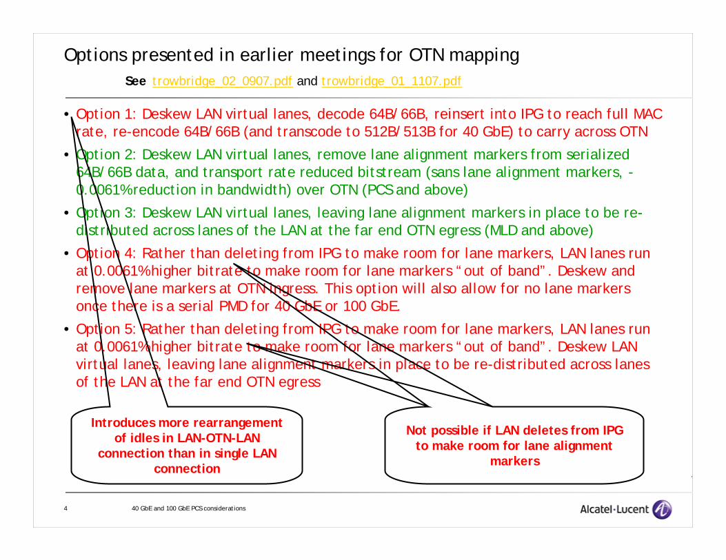
Options presented in earlier meetings for OTN mapping
• Option 1: Deskew LAN virtual lanes, decode 64B/66B, reinsert into IPG to reach full MAC rate, re-encode 64B/66B (and transcode to 512B/513B for 40 GbE) to carry across OTN
• Option 2: Deskew LAN virtual lanes, remove lane alignment markers from serialized 64B/66B data, and transport rate reduced bitstream (sans lane alignment markers, -0.0061% reduction in bandwidth) over OTN (PCS and above)
• Option 3: Deskew LAN virtual lanes, leaving lane alignment markers in place to be re-distributed across lanes of the LAN at the far end OTN egress (MLD and above)
• Option 4: Rather than deleting from IPG to make room for lane markers, LAN lanes run at 0.0061% higher bitrate to make room for lane markers “out of band”. Deskew and remove lane markers at OTN ingress. This option will also allow for no lane markers once there is a serial PMD for 40 GbE or 100 GbE.
• Option 5: Rather than deleting from IPG to make room for lane markers, LAN lanes run at 0.0061% higher bitrate to make room for lane markers “out of band”. Deskew LAN virtual lanes, leaving lane alignment markers in place to be re-distributed across lanes of the LAN at the far end OTN egress
See trowbridge_02_0907.pdf and trowbridge_01_1107.pdf
Introduces more rearrangement of idles in LAN-OTN-LAN
connection than in single LAN connection
Not possible if LAN deletes from IPG to make room for lane alignment
markers

5 40 GbE and 100 GbE PCS considerations
Lane Striping in 10G Base-X Interfaces10BLane 1
10B
10B
10B
10B
10B
10B
10B
10B
10B
10B
10B
10B
10B
10B
10B
10B
10B
10B
10B
10B
10B
10B
10B
10B
10B
10B
10B
10B
10B
10B
10B
10B
10B
10B
10B
/i/
/i/
/i/
/i/
/i/
/i/
/i/
/i/
Lane 2
Lane 3
Lane 4
Logical MII order
/i/
/i/
/i/
/i/
10B
10B
10B
10B
10B
10B
10B
10B
10B
10B
10B
10B
10B
10B
10B
10B
10B
10B
10B
10B
10B
10B
10B
10B
10B
10B
10B
10B
10B
10B
10B
10B
10B
10B
10B
10B
10B
10B
10B
10B
10B
10B
10B
10B
10B
10B
10B
10B
10B
10B
10B
10B
10B
10B
10B
10B
IPG – 12 byte nominal minimum≥7 bytes after IPG shrinkage if MII and PHY have different clocks
10B
10B
10B
10B
10B
10B
10B
10B
10B
10B
10B
10B
10B
10B
10B
10B
10B
10B
10B
10B
10B
10B
10B
10B
10B
10B
10B
10B
10B
10B
10B
10B
10B
10B
10B
10B
/i/
/i/
/i/
/i/
LM
LM
LM
LM
/i/
/i/
/i/
/i/
10B
10B
10B
10B
10B
10B
10B
10B
10B
10B
10B
10B
10B
10B
10B
10B
10B
10B
10B
10B
10B
10B
10B
10B
10B
10B
10B
10B
10B
10B
10B
10B
10B
10B
10B
10B
10B
10B
10B
10B
10B
10B
10B
10B
10B
10B
10B
10B
10B
10B
10B
10B
10B
10B
10B
10B
Lane 1
Lane 2
Lane 3
Lane 4
10B Lane alignment markers replace IPG characters in-placeLane alignment markers do not interrupt a packet
10B
10B
10B
10B
10B
10B
10B
10B
10B
10B
10B
10B
10B
10B
10B
10B
10B
10B
10B
10B
10B
10B
10B
10B
10B
10B
10B
10B
10B
10B
10B
10B
10B
10B
10B
10B
/i/
/i/
/i/
/i/
LM
LM
LM
LM
/i/
/i/
/i/
/i/
10B
10B
10B
10B
10B
10B
10B
10B
10B
10B
10B
10B
10B
10B
10B
10B
10B
10B
10B
10B
10B
10B
10B
10B
10B
10B
10B
10B
10B
10B
10B
10B
10B
10B
10B
10B
10B
10B
10B
10B
10B
10B
10B
10B
10B
10B
10B
10B
10B
10B
10B
10B
10B
10B
10B
10B
Lane Skew

6 40 GbE and 100 GbE PCS considerations
Lane Striping in 10G Base-X Interfaces
10BLane 1
10B
10B
10B
10B
10B
10B
10B
10B
10B
10B
10B
10B
10B
10B
10B
10B
10B
10B
10B
10B
10B
10B
10B
10B
10B
10B
10B
10B
10B
10B
10B
10B
10B
10B
10B
/i/
/i/
/i/
/i/
/i/
/i/
/i/
/i/
Lane 2
Lane 3
Lane 4
/i/
/i/
/i/
/i/
10B
10B
10B
10B
10B
10B
10B
10B
10B
10B
10B
10B
10B
10B
10B
10B
10B
10B
10B
10B
10B
10B
10B
10B
10B
10B
10B
10B
10B
10B
10B
10B
10B
10B
10B
10B
10B
10B
10B
10B
10B
10B
10B
10B
10B
10B
10B
10B
10B
10B
10B
10B
10B
10B
10B
10B
10B
10B
10B
10B
10B
10B
10B
10B
10B
10B
10B
10B
10B
10B
10B
10B
10B
10B
10B
10B
10B
10B
10B
10B
10B
10B
10B
10B
10B
10B
10B
10B
10B
10B
10B
10B
/i/
/i/
/i/
/i/
LM
LM
LM
LM
/i/
/i/
/i/
/i/
10B
10B
10B
10B
10B
10B
10B
10B
10B
10B
10B
10B
10B
10B
10B
10B
10B
10B
10B
10B
10B
10B
10B
10B
10B
10B
10B
10B
10B
10B
10B
10B
10B
10B
10B
10B
10B
10B
10B
10B
10B
10B
10B
10B
10B
10B
10B
10B
10B
10B
10B
10B
10B
10B
10B
10B
Lane 1
Lane 2
Lane 3
Lane 4
Deskew according to lane markers
Replace lane markers with idle characters, restoringoriginal IPG
No rate adaptation anywhere in the processIPG may grow or shrink if there is a clock difference between the GGMII and the PHY, butnever as a result of the lane alignment process (same for all previous Ethernet interfaces)
7 40 GbE and 100 GbE PCS considerations
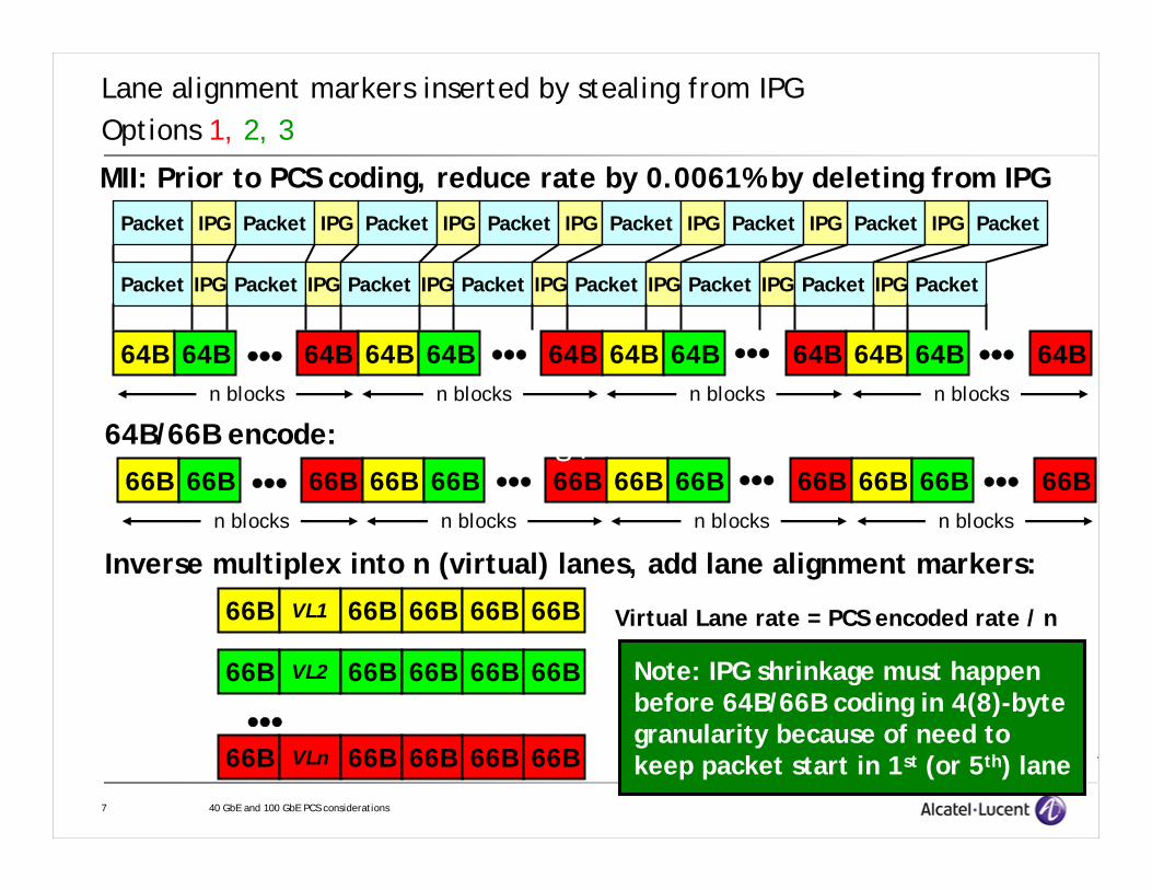
Lane alignment markers inserted by stealing from IPGOptions 1, 2, 3
66B 66B ••• 66B 66B 66B 66B 66B 66B 66B 66B 66B 66B
64B/66B encode:
Inverse multiplex into n (virtual) lanes, add lane alignment markers:
66B
66B
66B
VL1
VL2
VLn
66B 66B 66B 66B
66B 66B 66B 66B
66B 66B 66B 66B•••
••• ••• •••n blocks n blocks n blocks n blocks
64B 64B ••• 64B 64B 64B 64B 64B 64B 64B 64B 64B 64B••• ••• •••n blocks n blocks n blocks n blocks
MII: Prior to PCS coding, reduce rate by 0.0061% by deleting from IPGPacket IPG Packet IPG Packet IPG Packet IPG Packet IPG Packet PacketIPG IPG Packet
Packet IPG Packet IPG Packet IPG Packet IPG Packet IPG Packet IPG Packet IPG Packet
Note: IPG shrinkage must happenbefore 64B/66B coding in 4(8)-bytegranularity because of need tokeep packet start in 1st (or 5th) lane
Virtual Lane rate = PCS encoded rate / n
§4
8 40 GbE and 100 GbE PCS considerations
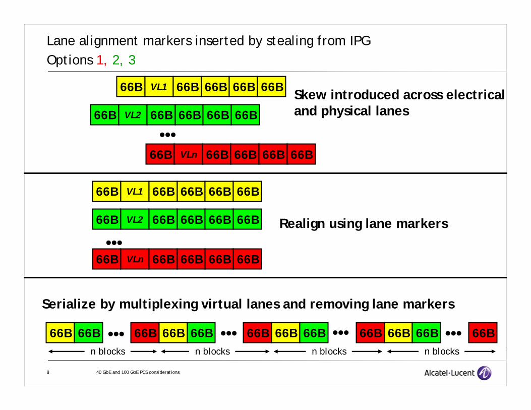
Lane alignment markers inserted by stealing from IPGOptions 1, 2, 3
66B
66B
66B
VL1
VL2
VLn
66B 66B 66B 66B
66B 66B 66B 66B
66B 66B 66B 66B
•••
Skew introduced across electricaland physical lanes
66B
66B
66B
VL1
VL2
VLn
66B 66B 66B 66B
66B 66B 66B 66B
66B 66B 66B 66B•••
Realign using lane markers
66B 66B ••• 66B 66B 66B 66B 66B 66B 66B 66B 66B 66B••• ••• •••n blocks n blocks n blocks n blocks
Serialize by multiplexing virtual lanes and removing lane markers

9 40 GbE and 100 GbE PCS considerations
Lane alignment markers inserted by stealing from IPGOptions 1, 2, 3
Decode 64B/66B
64B 64B ••• 64B 64B 64B 64B 64B 64B 64B 64B 64B 64B••• ••• •••n blocks n blocks n blocks n blocks
Add 0.0061% by adding to IPG to restore MII rateIPG added in 4 (or 8)-byte quanta since both MII and PCS coding rely onpacket start in lane 1 (or lane 5) only
Packet IPG Packet IPG Packet IPG Packet IPG Packet IPG Packet PacketIPG IPG Packet
Packet IPG Packet IPG Packet IPG Packet IPG Packet IPG Packet IPG Packet IPG Packet
10 40 GbE and 100 GbE PCS considerations
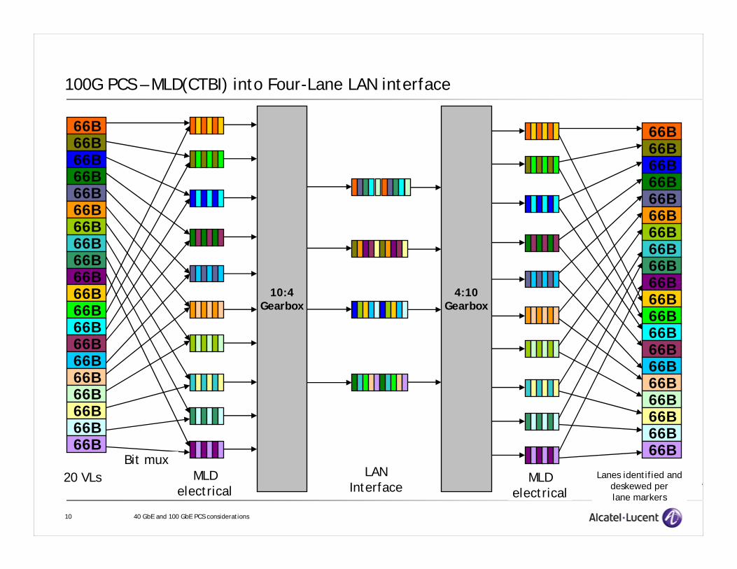
100G PCS – MLD(CTBI) into Four-Lane LAN interface
66B66B66B66B66B66B66B66B66B66B66B66B66B66B66B66B66B66B66B66B
20 VLs MLDelectrical
10:4Gearbox
LANInterface
4:10Gearbox
Bit mux
66B66B66B66B66B66B66B66B66B66B66B66B66B66B66B66B66B66B66B66B
MLDelectrical
Lanes identified anddeskewed perlane markers

11 40 GbE and 100 GbE PCS considerations
100G PCS – What might 100G Serial look like?
66B66B66B66B66B66B66B66B66B66B66B66B66B66B66B66B66B66B66B66B
20 VLs MLDelectrical
10:1Mux
LANInterface
1:10DeMux
Bit mux
66B66B66B66B66B66B66B66B66B66B66B66B66B66B66B66B66B66B66B66B
MLDelectrical
Lanes identified anddeskewed perlane markers
If the difference between PMDs is
“hidden” in a simple optical module, the
100G serial interface is not a
stream of 66B blocks, but a bit
mux of virtual lanes with skew, each
virtual lane consisting of 66B
blocks!

12 40 GbE and 100 GbE PCS considerations
Would this kind of 100 GbE Serial Interface formatbe suitable for an OTN mapping?
OTNOTN
OTN AOTN A OTN BOTN B
If the 100 GbE interface isserial, there is no problem.
Bit order is preserved,even across multiple
OTN domains
13 40 GbE and 100 GbE PCS considerations
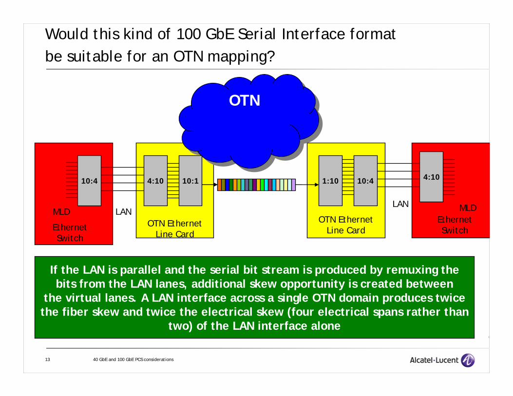
Would this kind of 100 GbE Serial Interface formatbe suitable for an OTN mapping?
OTNOTN
If the LAN is parallel and the serial bit stream is produced by remuxing thebits from the LAN lanes, additional skew opportunity is created between
the virtual lanes. A LAN interface across a single OTN domain produces twicethe fiber skew and twice the electrical skew (four electrical spans rather than
two) of the LAN interface alone
10:4
MLD
4:10
LAN
10:1
EthernetSwitch
OTN EthernetLine Card
1:10 10:4
OTN EthernetLine Card
EthernetSwitch
LAN
4:10
MLD
14 40 GbE and 100 GbE PCS considerations
OTNOTN
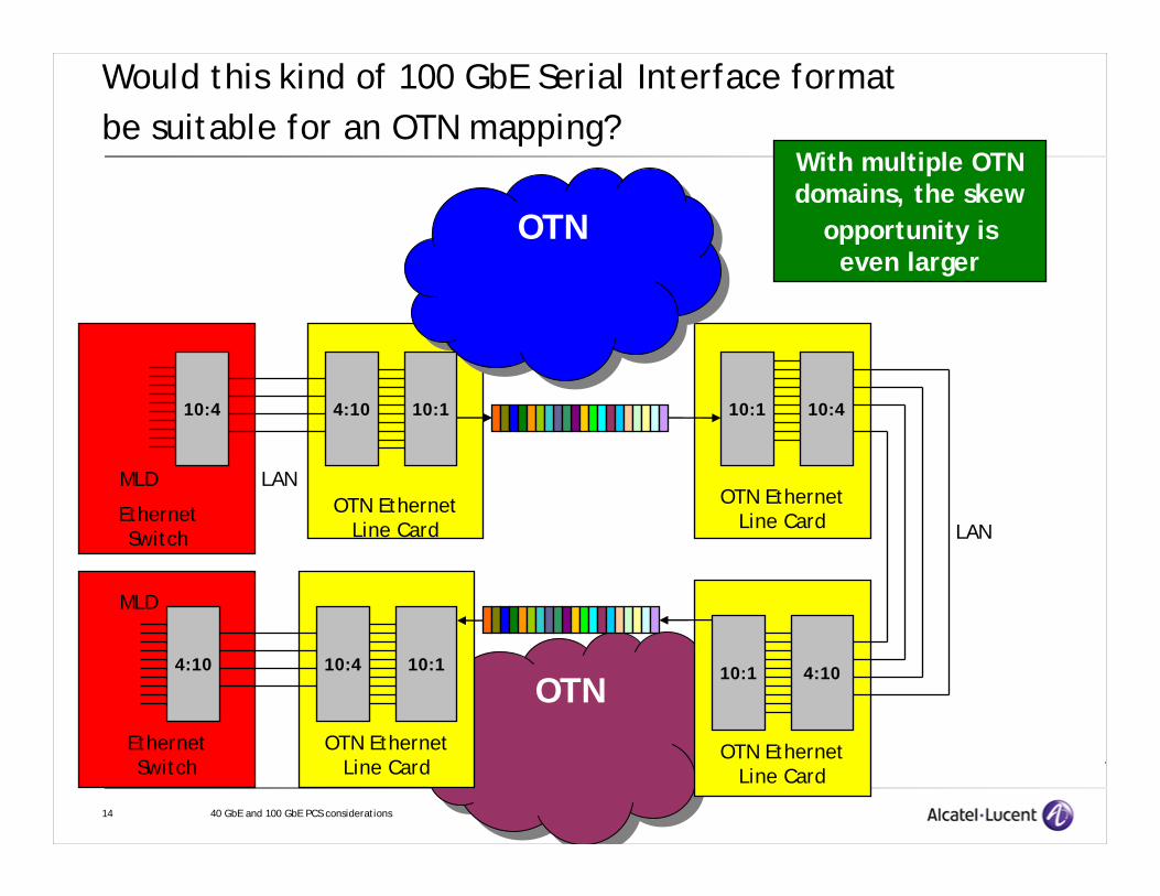
Would this kind of 100 GbE Serial Interface formatbe suitable for an OTN mapping?
OTNOTN
With multiple OTNdomains, the skew
opportunity iseven larger
10:4
MLD
4:10
LAN
10:1
EthernetSwitch
OTN EthernetLine Card
10:1 10:4
OTN EthernetLine Card
EthernetSwitch
LAN
4:10
MLD
OTN EthernetLine Card
4:1010:1
OTN EthernetLine Card
10:110:4

15 40 GbE and 100 GbE PCS considerations
So what format and architecture is best for 100 GbE over OTN?
Option A – Use serial LAN format (bit-mux of 20 virtual lanes) and build the LAN with several times (3-5?) the skew tolerance needed for the longest envisioned parallel LAN interface
Option B1 – Deskew the LAN virtual lanes at the OTN ingress (requires demuxing virtual lanes and recovering lane markers on each virtual lane). Remux the virtual lanes bitwise into a serial stream to carry across the OTN, where the serial bit order is preserved. Demux at a bit level at the OTN egress into the appropriate number of LAN lanesdepending on which PMD is chosen.
Option B2 – Deskew the LAN virtual lanes at the OTN ingress (requires demuxing virtual lanes and recovering 64B/66B on each virtual lane). Remultiplex into a serial stream by assembling the 66B blocks in correct temporal order, resulting in a bitstream that looks like 10G Base-R but faster. At the OTN egress, demux the 66B blocks into 20 virtual lanes, remux bitwise into the required number of LAN lanes.

16 40 GbE and 100 GbE PCS considerations
Four lane 40 GbE interface
66B
66B
66B
66B
66B
66B
66B
66B
66B
66B
66B
66B
66B 66B 66B
66B 66B 66B
66B 66B 66B
66B 66B 66B
66B
66B
66B
66B
66B
66B
66B
66B
66B
66B
66B
66B
Electrical and LANLanes are the same
Lanes identified anddeskewed perlane markers

17 40 GbE and 100 GbE PCS considerations
40 GbE PCS – What might 40 GbE Serial look like?
66B
66B
66B
66B
66B
66B
66B
66B
66B
66B
66B
66B
66B 66B 66B
66B 66B 66B
66B 66B 66B
66B 66B 66B
66B
66B
66B
66B
66B
66B
66B
66B
66B
66B
66B
66B
ElectricalMLD
Lanes identified anddeskewed perlane markers
66B 66B 66B
66B 66B 66B
66B 66B 66B
66B 66B 66B
ElectricalMLD
4:1Mux
1:4De-MuxBit-mux of
4 virtuallanes

18 40 GbE and 100 GbE PCS considerations
Issues with using bit-muxed VLs for 40 GbE over OTN
• If the LAN is parallel, there is the same problem with skew budget as with considering the bit-muxed VL format for 100 GbE. (Note that for serial LAN, there is no issue with extra skew)
• There is also the problem that the bit-rate exceeds the capacity of standard ODU3.
• This would steer towards option B2 from the earlier slide, as transcodingproposals are based on a series of 66B blocks.

19 40 GbE and 100 GbE PCS considerations
Conclusions• The concept of stealing from the IPG to make room for lane markers is not the same for
the MLD(CTBI)/virtual lane architecture as it was for 10G Base-X architectures:
Lane marker size of 264 bits (4x66B) (40 GbE) or 1340 bits (20x66B) cannot be accommodated “in place” in the IPG the way a 40 bit lane marker (4x10B) can be inserted in a 10G Base-X interface
Lane markers interrupt a packet
Lane markers for 40 GbE and 100 GbE will redistribute IPG across the interface since a direct replacement of idles with lane markers and lane markers with idles is not possible
Since the LAN is not transparent with respect to IPG (not really different from 10G, but not widely recognized at 10G), some new definition is required as to what constitutes a transparent mapping over OTN
• The logical serial LAN format that would follow from the MLD architecture is a bit-muxof virtual lanes rather than a sequence of 66B blocks.
For parallel LAN, deskew is likely needed at the OTN ingress which requires recovery of 66B blocks
66B blocks must also be recovered to perform transcoding for 40 GbE into ODU2
Option B2 appears to best meet the needs for a common method for OTN transport of parallel or serial 40 GbE and 100 GbE