40 air consumption air consumptionreduction in … · series asr/series asq 40% 40 air consumption...
TRANSCRIPT
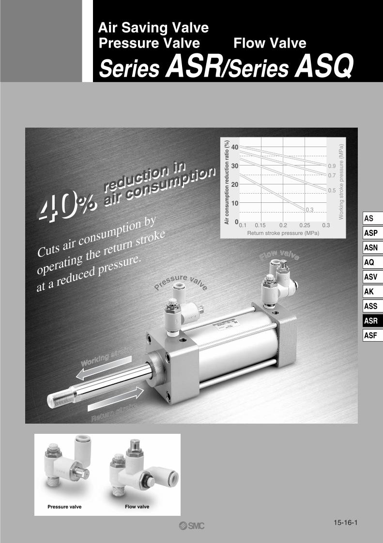
Air Saving ValvePressure Valve Flow Valve
Series ASR/Series ASQ
40% reduction in
air consumption
40% reduction in
air consumption
Pressure valve Flow valve
Cuts air consumption by
operating the return stroke
at a reduced pressure.
0
10
20
30
40
0.1 0.15 0.2 0.25 0.3Return stroke pressure (MPa)
Air
con
sum
ptio
n re
duct
ion
ratio
(%)
Wor
king
str
oke
pres
sure
(M
Pa)
0.3
0.5
0.7
0.9
Working stroke
Working stroke
Return stroke
Return stroke
Pressure valvePressure valve
Flow valveFlow valve
15-16-1
AS
ASP
ASN
AQ
ASV
AK
ASS
ASR
ASF

Cuts air consumption by operatingthe return stroke at a reduced pressure.
Cuts air consumption by operatingthe return stroke at a reduced pressure.
Conventional valve Air saving valveWorking and return strokes
operated at the same pressureReturn stroke operatedat a reduced pressure
Pressurevalve
Working stroke
Return stroke
Flow valve
Working stroke
Return stroke
Regulator with check valve+
Speed controller
Quick supply and exhaust valve+
Speed controller(Meter-in, Meter-out)
Pressure valve Flow valve
Series ASR Series ASQ
Return stroke
Working stroke
15-16-2
Pressure valve
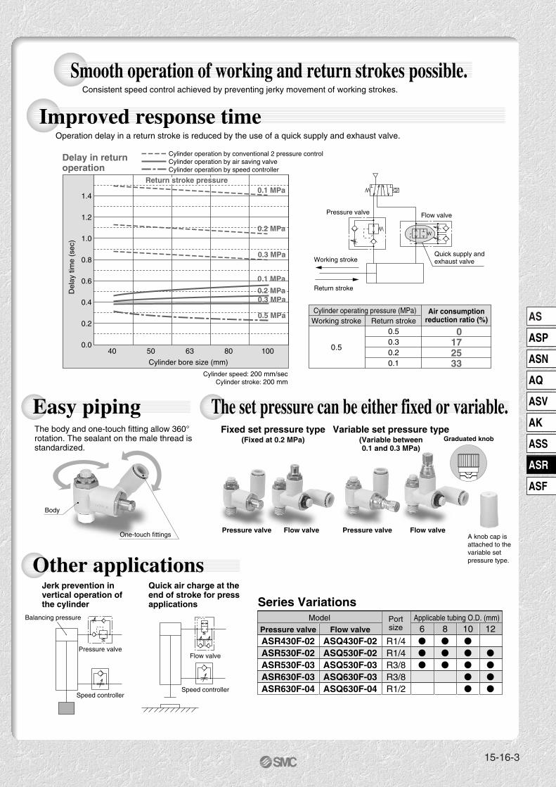
ASR430F-02ASR530F-02ASR530F-03ASR630F-03ASR630F-04
Flow valve
ASQ430F-02ASQ530F-02ASQ530F-03ASQ630F-03ASQ630F-04
R1/4R1/4R3/8R3/8R1/2
Model
Series VariationsApplicable tubing O.D. (mm)Port
size
Jerk prevention in vertical operation of the cylinder
Quick air charge at the end of stroke for pressapplications
Balancing pressure
Pressure valve
Speed controller
Flow valve
Speed controller
Fixed set pressure type(Fixed at 0.2 MPa)
Pressure valve Flow valve Pressure valve Flow valve
Variable set pressure type(Variable between0.1 and 0.3 MPa)
2
3
Graduated knob
A knob cap is attached to the variable set pressure type.
Body
One-touch fittings
Improved response time Operation delay in a return stroke is reduced by the use of a quick supply and exhaust valve.
Smooth operation of working and return strokes possible. Consistent speed control achieved by preventing jerky movement of working strokes.
Other applications
The set pressure can be either fixed or variable.Easy pipingThe body and one-touch fitting allow 360° rotation. The sealant on the male thread is standardized.
Delay in return operation
1.4
0.0
0.2
0.4
0.6
0.8
1.0
1.2
40 50 63 80 100
Cylinder bore size (mm)
Del
ay ti
me
(sec
)
0.1MPa
0.2MPa0.3MPa
0.5MPa
0.1MPa
0.2MPa
0.3MPa
0.1 MPa
0.2 MPa0.3 MPa
0.5 MPa
0.1 MPa
0.2 MPa
0.3 MPa
Cylinder operation by conventional 2 pressure controlCylinder operation by air saving valveCylinder operation by speed controller
Quick supply and exhaust valve
Flow valve
Working stroke
Return stroke
Pressure valve
Working stroke
0.5
Cylinder operating pressure (MPa)
Cylinder speed: 200 mm/secCylinder stroke: 200 mm
Air consumptionreduction ratio (%)Return stroke
0.50.30.20.1
0172533
6 8 10 12
Return stroke pressure
15-16-3
AS
ASP
ASN
AQ
ASV
AK
ASS
ASR
ASF
Cuts air consumption by operatingthe return stroke at a reduced pressure.
Air Saving ValvePressure Valve Flow Valve
Series ASR/Series ASQ
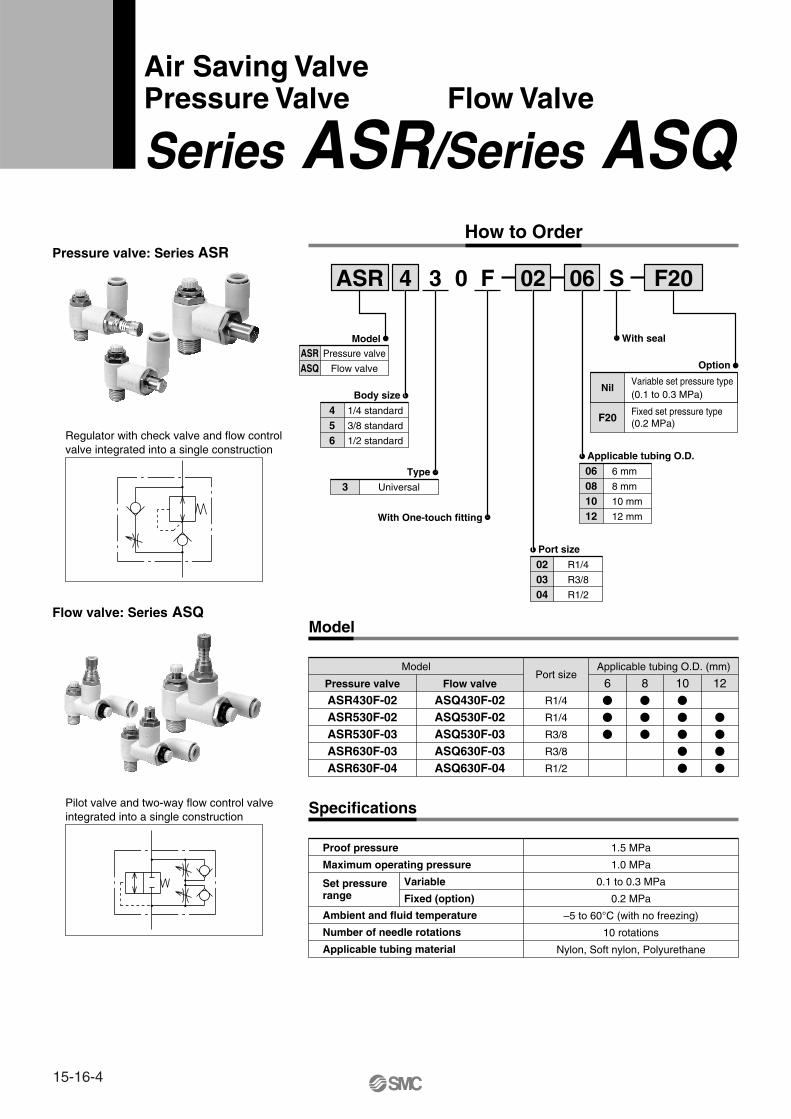
Model Applicable tubing O.D. (mm)Port size
Pressure valve
ASR430F-02ASR530F-02ASR530F-03ASR630F-03ASR630F-04
Flow valve
ASQ430F-02ASQ530F-02ASQ530F-03ASQ630F-03ASQ630F-04
R1/4
R1/4
R3/8
R3/8
R1/2
Proof pressure
Maximum operating pressure
Set pressure range
Ambient and fluid temperature
Number of needle rotations
Applicable tubing material
1.5 MPa
1.0 MPa
0.1 to 0.3 MPa
0.2 MPa
–5 to 60°C (with no freezing)
10 rotations
Nylon, Soft nylon, Polyurethane
Model
Variable
Fixed (option)
How to Order
ASR F204 3 0 F S02 06
06081012
6 mm
8 mm
10 mm
12 mm
020304
R1/4
R3/8
R1/2
456
1/4 standard
3/8 standard
1/2 standard
ASRASQ
Pressure valve
Flow valve
3 Universal
Nil
F20
Variable set pressure type(0.1 to 0.3 MPa)
Fixed set pressure type(0.2 MPa)
Model
Option
Applicable tubing O.D.
With seal
Port size
Body size
Type
With One-touch fitting
Regulator with check valve and flow control valve integrated into a single construction
Pilot valve and two-way flow control valve integrated into a single construction
Pressure valve: Series ASR
Flow valve: Series ASQ
Specifications
6 8 10 12
15-16-4

Effective Area
Pressure Valve: Series ASR
Type Free flowmm2
Controlled flowmm2
ASR430F-02-06S(-F20)ASR430F-02-08S(-F20)ASR430F-02-10S(-F20)ASR530F-02-06S(-F20)ASR530F-02-08S(-F20)ASR530F-02-10S(-F20)ASR530F-02-12S(-F20)ASR530F-03-06S(-F20)ASR530F-03-08S(-F20)ASR530F-03-10S(-F20)ASR530F-03-12S(-F20)ASR630F-03-10S(-F20)ASR630F-03-12S(-F20)ASR630F-04-10S(-F20)ASR630F-04-12S(-F20)
5.45.95.97.38.99.29.57.38.99.29.5
15.316.015.316.0
5.96.76.78.1
11.813.313.78.1
11.813.313.717.819.117.819.1
Flow Valve: Series ASQ
ASQ430F-02-06S(-F20)ASQ430F-02-08S(-F20)ASQ430F-02-10S(-F20)ASQ530F-02-06S(-F20)ASQ530F-02-08S(-F20)ASQ530F-02-10S(-F20)ASQ530F-02-12S(-F20)ASQ530F-03-06S(-F20)ASQ530F-03-08S(-F20)ASQ530F-03-10S(-F20)ASQ530F-03-12S(-F20)ASQ630F-03-10S(-F20)ASQ630F-03-12S(-F20)ASQ630F-04-10S(-F20)ASQ630F-04-12S(-F20)
4.14.64.66.69.29.8
10.86.69.29.8
10.815.316.215.316.2
4.95.55.57.8
10.110.811.67.8
10.110.811.617.118.017.118.0
Operating Principle
Working Stroke Return Stroke
1. The cylinder starts smoothly because jerks are prevented by meter-in control.
3. To prevent delay due to the pressure gap, air is rapidly exhausted to decrease the pressure from D to E, after which the piston moves at a constant speed. If a speed controller is used instead of the flow valve, exhausting air will take more time as illustrated by line D-F, resulting in longer stop time of the cylinder and a consequent time loss.
4. The cylinder operates at a low pressure required for a return.
2. When the cylinder reaches the stroke end, the quick air charge by the flow valve rapidly increases the rear side pressure (PH) from A to B. If a speed controller is used instead of the flow valve, charging air will take more time as illustrated by line A-C, causing delay in the pressure rise.
Working stroke
Jerkprevention
Return stroke
Quick exhaust
Quick supplyLow pressure operation
Type Meter-outmm2
Meter-inmm2
CB
A
Cylind
erm
ovem
ent
PRPH
Time
Pre
ssur
e, S
trok
e
PR
PH
F
E
D
PH
Cylinder movem
ent by
speed control valve
Cylinder movem
ent
by flow valve
PRPH
PR
Time
Pre
ssur
e, S
trok
e
15-16-5
Series ASR/ASQ
AS
ASP
ASN
AQ
ASV
AK
ASS
ASR
ASF
Air Saving ValvePressure Valve/Flow Valve

Selection and Adjustment
SeriesASR
Pressure valveSeriesASQ
Flow valve
SeriesASR
Pressure valve
SeriesASQ
Flow valve
High pressure side
High pressure side
Low pressure side
Low pressure side
High pressure side
Low pressure side
Wor
king
str
oke
Ret
urn
stro
ke
Return stroke
Working stroke
Install a flow valve on the working side which requires the cylinder output and a pressure valve on the return side. The product cannot be used in cases where the same pressure is necessary for both working and return strokes. In such cases use a speed controller.
Horizontal mountingLow pressure side: Pressure valveHigh pressure side: Flow valve
Vertical mountingLow pressure side: Pressure valveHigh pressure side: Flow valve
Low pressure side: Pressure valveHigh pressure side: Dual speed controller
Refer to
Adjustment Procedure 1for pressure and speed adjustment.
Refer to
Adjustment Procedure 1for pressure and speed adjustment.
Refer to
Adjustment Procedure 2for pressure and speed adjustment.
In case the load ratio is 50% or lower at the set pressure of the flow valve:
SeriesASR
Pressure valve
SeriesASD
Dual speed controller(Meter-in • Meter-out)
Wor
king
str
oke
Ret
urn
stro
ke
If the load ratio at the set pressure of the flow valve exceeds 50%, install a dual speed controller (meter-in and meter out control) on the high pressure side.
Series ASR/ASQ
15-16-6

1. The cylinder speed is adjusted with knobs C , D and E . First have all the knobs fully closed and then open them gradually for adjustment. Turn the knob clockwise to close (decrease the speed of the piston rod) and counterclockwise to open (increase the speed of the piston rod).
2. Speed adjustment for the working strokeThe speed is adjusted with the pressure valve and the flow valve.Open knobs C and E gradually until the required speed is achieved. Make sure that knobs C and E are opened by the same number of rotations.Note 1) If the piston rod jerks, close knob E until the smooth
operation is achieved.3. Speed adjustment for return stroke
The speed is adjusted with the flow valve.Open knob D gradually until the required speed is achieved.
4. Be sure to tighten the lock nut after adjustment.
1. The cylinder speed is adjusted with knobs C , F and G . First have all the knobs fully closed and then open them gradually for adjustment. Turn the knob clockwise to close (decrease the speed of the pistoin rod) and counterclockwise to open (increase the speed of the piston rod).
2. Speed adjustment for the working strokeThe speed is adjusted with the pressure valve and the dual speed controller.Open knobs C and G gradually until the required speed is achieved. Make sure that knobs C and G are opened by the same number of rotations.Note 1) If the piston rod jerks, close knob G until the smooth
operation is achieved.3. Speed adjustment for return stroke
The speed is adjusted with the dual speed controller.Open knob F gradually until the required speed is achieved.
4. Be sure to tighten the lock nut after adjustment.
Adjustment Procedure 1Pressure Adjustment Speed Control
Adjustment Procedure 2
1. The fixed set pressure type (-F20) does not require adjustment because the pressure is fixed at 0.2 MPa for both the pressure valve and the flow valve.
2. The set pressures of the variable set pressure type pressure valve and flow valve are adjusted with knob A and knob B respectively. Turn the knob clockwise to increase the pressure and counterclockwise to decrease the pressure.
3. The graduations 1, 2 and 3 correspond to 0.1, 0.2 and 0.3 MPa respectively. Align the bottom end of the knob with the graduated line for adjustment.
4. Set the same pressure for the pressure valve and the flow valve (0.2 MPa as the recommended value).
5. The inlet side should be supplied with a pressure which is higher than the set pressure by 0.1 MPa or more.
6. Cap the valve after adjustment.
2
3
Knob Align the bottom end of the knob with the graduated line.The figure illustrates the case in which the pressure is set at 0.2 MPa.
Pressure Valve: Series ASR Flow Valve: Series ASQ
Pressure Valve: Series ASR Dual Speed Controller: Series ASD
Pressure Adjustment Speed Control
1. The fixed set pressure type (-F20) does not require adjustment because the pressure is fixed at 0.2 MPa.
2. The pressure at the low pressure side (return stroke side) is adjusted by the pressure valve.
3. The set pressure is adjusted with knob A . Turn the knob clockwise to increase the pressure and counterclockwise to decrease the pressure.
4. The graduations 1, 2 and 3 correspond to 0.1, 0.2 and 0.3 MPa respectively. Align the bottom end of the knob with the graduated line for adjustment.
5. Keep the set pressure as low as possible in order to achieve good air saving effect.
6. Cap the valve after adjustment.
A
C
Knob
Knob
DKnob
BKnob
EKnob
CKnob
AKnob
FKnob
GKnob
15-16-7
Series ASR/ASQ
AS
ASP
ASN
AQ
ASV
AK
ASS
ASR
ASF
Air Saving ValvePressure Valve/Flow Valve

Construction
Variable type Fixed type
No.
q
w
e
r
t
y
u
i
o
!00
!1
!2
!3
Description
Body A
Body B
Seat ring
Body B1
Body B2
Body C
Stopper
Valve
Piston
Adjustment screw
Knob
Cap
Adjustment spring
Material
PBT
Brass
Brass
Brass
Brass
Brass
Stainless steel
HNBR/Brass
Brass
Brass
Brass
Polypropylene
Steel wire
Note
Electroless nickel plated
Electroless nickel plated
Electroless nickel plated
Electroless nickel plated
Electroless nickel plated
Electroless nickel plated
Electroless nickel plated
Zinc chromated
Component PartsNo.
!4
!5
!6
!7
!8
!9
@0
@1
@22
@3
@44
@5
Description
U seal
Body C
Adjustment plug
Needle
Knob
Lock nut Note 1)
U seal
Elbow body
Spacer Note 2)
Cassette
Seal
Drive body Note 3)
Material
HNBR
Brass
Brass
Brass
PBT
Steel
HNBR
PBT
PBT
Stainless steel/POM
NBR
Brass
Note
Electroless nickel plated
Electroless nickel plated
Electroless nickel plated
Electroless nickel plated
Electroless nickel plated
Note 1) Brass is used for the material ASR530F and ASR630F.Note 2) Not used for ø6 and ø8.Note 3) Not used for ø10 and ø12.
@1 @2 @5 @4 @3 @1 @2 @5 @4 @3
u o !3 u o !3!8
!9
!7
w
q
@0
e
!8
!9
!7
w
q
@0
e!4
!8 u o !3 !8 u o !3
i y !0 !1 !2 !4 i !5 !6
!7
!9
t
q
@0
r
!7
!9
t
q
@0
r
!4 i y !0 !1 !2 !4 i !5 !6
Pressure Valve: Series ASR
ASR430F-02 typeASR530F-03 typeASR630F-04 type
ASR530F-02 typeASR630F-03 type
ASR430F-02 typeASR530F-03 typeASR630F-04 type
ASR530F-02 typeASR630F-03 type
Series ASR/ASQ
15-16-8

Variable type Fixed type
Description
Body A
Body B
Seat ring
Body B1
Body B2
Adjustment screw
Knob
Cap
Adjustment plug
Body C
Body D1
Body D2
Body D3
Material
PBT
Brass
Brass
Brass
Brass
Brass
Brass
Polypropylene
Brass
Brass
Brass
Brass
Brass
Note
Electroless nickel plated
Electroless nickel plated
Electroless nickel plated
Electroless nickel plated
Electroless nickel plated
Electroless nickel plated
Electroless nickel plated
Electroless nickel plated
Electroless nickel plated
Electroless nickel plated
Electroless nickel plated
Component Parts Description
Piston valve
Adjustment spring
Needle
Knob
Lock nut Note 1)
Lock nut Note 1)
U seal
U seal
Elbow body
Spacer Note 2)
Cassette
Seal
Drive body Note 3)
Material
HNBR/Brass
Steel wire
Brass
PBT
Steel
Steel
HNBR
HNBR
PBT
PBT
Stainless steel/POM
NBR
Brass
Note
Zinc chromated
Electroless nickel plated
Electroless nickel plated
Black zinc chromated
Electroless nickel plated
Note 1) Brass is used for the material ASQ530F and ASQ630F.Note 2) Not used for ø6 and ø8.Note 3) Not used for ø10 and ø12.
@2 @5@6 @4@3 @2 @5@6 @4@3
!8
!6
!7
w
q
@0
e
!8
!6
!7
w
q
@0
e
!6
!8
!7
t
q
@0
r
!6
!8
!7
t
q
@0
r
y
u
i
!5
!2
!4
!1
o
!5
!3
!4
!1
y
u
i
!5
!2
!4
!1
y
!5
!3
!4
!1
@1 !0 !9 !6 !7 @1 !0 !9 !6 !7
@1 !0 !9 !6 !7 @1 !0 !9 !6 !7
Flow Valve: Series ASQ
ASQ430F-02 typeASQ530F-03 typeASQ630F-04 type
ASQ530F-02 typeASQ630F-03 type
ASQ430F-02 typeASQ530F-03 typeASQ630F-04 type
ASQ530F-02 typeASQ630F-03 type
No.
q
w
e
r
t
y
u
i
o
!00
!1
!2
!3
No.
!4
!5
!6
!7
!8
!9
@0
@1
@22
@3
@44
@5
@6
15-16-9
Series ASR/ASQ
AS
ASP
ASN
AQ
ASV
AK
ASS
ASR
ASF
Air Saving ValvePressure Valve/Flow Valve
ASQ530FASQ430F
ASQ630F
ASQ630F
ASQ530F
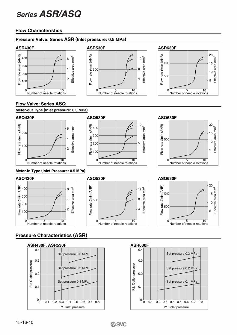
Flow Characteristics
Pressure Valve: Series ASR (Inlet pressure: 0.5 MPa)
20
15
10
5
500
100
200
300
400
5
10
20
15
10
5
1000
500
500
4
8
12
100
200
300
400
2
4
6
100
200
2
4
6
ASR430F ASR530F ASR630F
20
15
10
5
1000
500
1050
500
4
8
12
10501050
100
200
300
400
2
4
6
Number of needle rotations
Flo
w r
ate l/m
in (
AN
R)
Effe
ctiv
e ar
ea m
m2
ASQ430F
105010501050
105010501050
Flow Valve: Series ASQ
Meter-in Type (Inlet Pressure: 0.5 MPa)
ASR430F, ASR530F ASR630F
Pressure Characteristics (ASR)
0
0.1
0.2
0.3
0.4
0 0.1 0.2 0.3 0.4 0.5 0.6 0.7 0.8 0 0.1 0.2 0.3 0.4 0.5 0.6 0.7 0.8
P1: Inlet pressure
P2:
Out
let p
ress
ure
Set pressure 0.1 MPa
Set pressure 0.2 MPa
Set pressure 0.3 MPa
0
0.1
0.2
0.3
0.4
P1: Inlet pressure
P2:
Out
let p
ress
ure
Set pressure 0.3 MPa
Set pressure 0.1 MPa
Set pressure 0.2 MPa
Number of needle rotationsF
low
rat
e l/m
in (
AN
R)
Effe
ctiv
e ar
ea m
m2
Number of needle rotations
Flo
w r
ate l/m
in (
AN
R)
Effe
ctiv
e ar
ea m
m2
Number of needle rotations
Flo
w r
ate l/m
in (
AN
R)
Effe
ctiv
e ar
ea m
m2
Number of needle rotations
Flo
w r
ate l/m
in (
AN
R)
Effe
ctiv
e ar
ea m
m2
Meter-out Type (Inlet pressure: 0.3 MPa)
Series ASR/ASQ
15-16-10
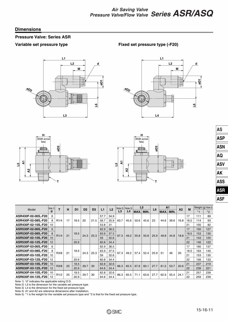
Dimensions
Variable set pressure type Fixed set pressure type (-F20)
Pressure Valve: Series ASR
H
L6
øD
1
L2
M
øD2
L1
A2
A1
L5
øD
3
L4
d
T
øD
1
øD
3
H
A2
A1
L5
øD2
L6
M
L2
L1
L3
d
T
Model T H D1 D2 D3 L1 L2 L6 A2 ML5 A1 Weight (g) Note 5)
MAX. MIN. MAX. MIN. ∗1 ∗2Note 1)
dNote 2)
L3Note 3)
L4
ASR430F-02-06S,-F20ASR430F-02-08S,-F20ASR430F-02-10S,-F20ASR530F-02-06S,-F20ASR530F-02-08S,-F20ASR530F-02-10S,-F20ASR530F-02-12S,-F20ASR530F-03-06S,-F20ASR530F-03-08S,-F20ASR530F-03-10S,-F20ASR530F-03-12S,-F20ASR630F-03-10S,-F20ASR630F-03-12S,-F20ASR630F-04-10S,-F20ASR630F-04-12S,-F20
6
8
10
6
8
10
12
6
8
10
12
10
12
10
12
18.5
18.5
20.9
18.5
20.9
18.5
20.9
18.5
20.9
57.7
58.7
53.8
62.9
63.9
59
60.8
62.9
63.9
59
60.8
62.8
64.6
62.8
64.6
34.9
35.9
31
36.5
37.5
32.6
34.4
36.5
37.5
32.6
34.4
32.6
34.4
32.6
34.4
17
18.5
21
17
18.5
21
22
17
18.5
21
22
21
22
21
22
111
114
105
150
153
143
146
160
163
153
156
237
239
257
259
89
93
82
127
130
120
122
137
140
130
133
219
221
239
239
R1/4
R1/4
R3/8
R3/8
R1/2
17
21
21
25
25
20
24.3
24.3
29.7
29.7
21.5
25.3
25.3
30
30
63.7
67.3
67.3
86.3
86.3
45.6
49.2
49.2
65.5
65.5
50.6
55.8
57.4
67.6
71.1
45.6
50.8
52.4
60.1
63.6
23
25.9
25.9
27.7
27.7
44.6
49.8
51
61.2
62.9
39.6
44.8
46
53.7
55.4
16.8
18.8
20
20.6
24.1
Note 1) “d” indicates the applicable tubing O.D.Note 2) L3 is the dimension for the variable set pressure type.Note 3) L4 is the dimension for the fixed set pressure type.Note 4) A1 and A2 are reference dimensions after installation.Note 5) ∗1 is the weight for the variable set pressure type and ∗2 is that for the fixed set pressure type.
(Width acrossflats)
(Width acrossflats)
15-16-11
Series ASR/ASQ
AS
ASP
ASN
AQ
ASV
AK
ASS
ASR
ASF
Air Saving ValvePressure Valve/Flow Valve

Variable set pressure type Fixed set pressure type
Flow Valve: Series ASQ
Model HT D1 D2 D4 L3L1 L2 Note 2)L5
Note3)L6 L8 Note 4)
A2 ML7L4 A1 Note 4) Weight (g) Note 5)
MAX. MIN.MAX. MIN. MAX. MIN. ∗1 ∗2Note 1)
d
ASQ430F-02-06S,-F20ASQ430F-02-08S,-F20ASQ430F-02-10S,-F20ASQ530F-02-06S,-F20ASQ530F-02-08S,-F20ASQ530F-02-10S,-F20ASQ530F-02-12S,-F20ASQ530F-03-06S,-F20ASQ530F-03-08S,-F20ASQ530F-03-10S,-F20ASQ530F-03-12S,-F20ASQ630F-03-10S,-F20ASQ630F-03-12S,-F20ASQ630F-04-10S,-F20ASQ630F-04-12S,-F20
6
8
10
6
8
10
12
6
8
10
12
10
12
10
12
18.5
18.5
20.9
18.5
20.9
18.5
20.9
18.5
20.9
61.6
62.6
57.7
65.6
66.6
61.7
63.5
65.6
66.6
61.7
63.5
74.8
76.6
74.8
76.6
34.9
35.9
31
36.5
37.5
32.6
34.4
36.5
37.5
32.6
34.4
32.6
34.4
32.6
34.4
17
18.5
21
17
18.5
21
22
17
18.5
21
22
21
22
21
22
136
139
130
178
181
172
174
188
191
182
184
310
312
330
332
114
117
108
155
158
149
151
165
168
159
161
292
294
312
314
17
21
21
25
25
R1/4
R1/4
R3/8
R3/8
R1/2
20
24.3
24.3
29.7
29.7
D3
21.5
24.8
24.8
30.7
30.7
19.5
20.4
20.4
30
30
20.3
23.4
23.4
30.8
30.8
88.8
92.2
93.8
107.9
111.4
68.7
72
73.6
86.9
90.4
49.4
53.5
53.5
74.3
74.3
44.4
48.5
48.5
66.8
66.8
50.6
55.8
57.4
67.6
71.1
45.6
50.8
52.4
60.1
63.6
23
25.6
25.6
28
28
44.6
49.8
51
61.2
62.9
39.6
44.8
46
53.7
55.4
17.9
19
20.2
20.8
24.1
Note 1) “d” indicates the applicable tubing O.D..Note 2) L5 is the dimension for the variable set pressure type.Note 3) L6 is the dimension for the fixed set pressure type.Note 4) A1 and A2 are reference dimensions after installation.Note 5) ∗1 is the weight for the variable set pressure type and ∗2 is that for the fixed set pressure type.
L6
L8
M
L2
L1
øD2
L3
L4
øD
3
øD
1
øD4
H
A2
A1
L7
d
T
øD2
øD
3
øD
1L
8
øD4
H
A2
A1
L3
M
L2
L1
L5
L4
L7
d
T
(Width acrossflats) (Width across
flats)
Dimensions
Series ASR/ASQ
15-16-12
1. Read the instruction manual carefully.The instruction manual should be carefully read and fully understood before the product is installed and operated. Also, the manual should be kept where it can be easily referred to at any time.
2. Allow space for maintenance.Allow the space necessary for maintenance and inspections.
3. Tighten screws with the proper tightening torque.When mounting the product, tighten screws with the recom-mended torque.
Installation
1. Preparation before pipingBefore piping is connected, it should be thoroughly blown out with air (flushing) or washed to remove chips, cutting oil and other debris from inside the pipe.
3. Wrapping of sealant tapeWhen screwing together pipes, fittings, etc., be certain that chips from the pipe threads and sealant material do not get inside the piping.Further, when sealant tape is used, leave 1.5 to 2 thread ridges exposed at the end of the threads.
Piping
Warning
Caution
1. Confirm the specifications.The products appearing in this catalog are designed for use only in compressed air (included vacuum pressure) systems.Do not use outside the specified ranges of pressure, tempera-ture, etc., as this may cause damage or malfunction. (Refer to specifications.)Please consult with SMC if fluids other than compressed air (in-cluded vacuum pressure) are to be used.
Selection
Warning3. Drain flushing management
If the air filter drains are not flushed regularly, the condensate will flow downstream from the drains, resulting in malfunction of the pneumatic equipment.In cases where drain flushing will be difficult, use of filters with auto drain is recommended.For detailed information on the quality of compressed air, refer to Best Pneumatics Vol. 14.
4. Types of airDo not use compressed air containing chemicals, salt, corro-sive gases, synthetic oil which includes organic solvents, etc., which may cause damage or faulty operation.
Air Supply
Caution
1. Do not use valves where there is direct contact with, or in atmospheres of, corrosive gases, chemicals, salt water, water or steam.
2. Provide shade in locations which receive direct sunlight.
3. Do not operate in locations where vibration or impact occurs.
4. Do not operate in locations where the product is exposed to direct heat radiation from a heat source at a close distance.
Operating Environment
Warning
1. Maintenance should be performed in accor-dance with the procedures in the instruction manual.Incorrect handling can cause damage or malfunction of machinery and equipment, etc.
2. Maintenance workCompressed air can be dangerous if handled improperly. Element replacement and other maintenance etc., should be performed by personnel having sufficient knowledge and experience pertaining to pneumatic equipment, while also adhering to the product specifications.
3. Drain flushingCondensate should be flushed from the air filter and other drains on a regular basis.
4. Pre-maintenance checksWhen the product is to be removed, be sure to shut off the supply pressure, release compressed air in the pipelines and confirm an atmospheric release condition before proceeding.
5. Post-maintenance checksAfter mounting, repair or renovation, supply compressed air and perform suitable function and leak tests. If an audible leak is detected or equipment does not operate properly, stop operation and confirm that mounting is correct.
6. Disassembly and modification is prohibited.Do not disassemble or modify the main unit.
Maintenance
Warning
1. Types of fluidThis product is designed for use with compressed air. Please contact SMC if a different type of fluid is to be used.Please contact SMC regarding products for general fluids, to confirm which fluids can be used.
2. A large amount of condensatePressurized air containing a large amount of condensate may cause malfunction of the pneumatic equipment. An air dryer or water separator should be installed upstream from the filters.
Air Supply
Warning
Air Saving Valve Specific Product PrecautionsBe sure to read before handling.
15-16-13
AS
ASP
ASN
AQ
ASV
AK
ASS
ASR
ASF

1. Confirm that the lock nut is not loose.If the lock nut is loose, there may be dangerous changes in actuator speed.
2. The number of opening and closing rotations of the needle valve and adjustment screw should be adjusted within the range of the specifications.Since it has a pull-out stop mechanism, it will not rotate past the limit. Confirm the number of rotations for the product being used, as excessive turning of the needle will cause damage.
3. To adjust the speed, start with the needle in the completely closed position, and then adjust by opening gradually.When the needle valve is opening, the actuator may jerk suddenly creating a dangerous situation.Moreover, the needle valve is closed by turning clockwise, and opened by turning counterclockwise. Therefore, the actuator speed is reduced by turning clockwise and increased by turning counterclockwise.When the product is used for an actuator operating vertically, the actuator may lurch depending on the load. For the adjustment method, please refer to “Selection and Adjustment” on page 15-16-6 to 15-16-7.
4. For installation and removal, tighten the body B by applying an appropriate wrench to the two opposite sides of the hexagon.Using other parts may destroy the valve. For alignment after installation, rotate body A manually.
5. Do not use universal type fittings at a posi-tion where they are constantly rotated.The fittings may be damaged.
6. The valve cannot be used if there are fluctu-ations of the load.The piston rod may jerk during operation.
7. In case a closed-center solenoid valve is used, switch to the center position only after pres-sure charge inside the cylinder at the stroke end is completed.If the pressure charge is insufficient, the piston rod may jerk after restart.
Installation
Warning
1. The product cannot be used as a stop valve, of which zero leakage is required.The specifications of the product allow a certain degree of leakage.
2. Confirm whether PTFE can be used.The sealing compound contains PTFE (tetrafluoroethylene resin) powder. Make sure that it will not cause any problem in operation.
3. Keep the set pressure range of the outlet pressure of the pressure valve within 85% that of the inlet pressure.If the value exceeds 85%, the pressure may become unstable, affected by the fluctuation of the inlet pressure.
Selection
Warning1. The proper tightening torque for pipe fittings is as
shown in the table. As a rule, they should be tightened 2 to 3 turns with a tool after first tightening by hand. Be careful not to cause damage by over-tightening.
Tightening Torque
Caution
1. Installation and Removal of Tubing for One-Touch Fittings
1) Installation of tubing(1) Using tube cutters TK-1, 2 or 3, take a tube having no
flaws on its periphery and cut it off at a right angle. Do not use pinchers, nippers or scissors, etc. The tubing might be cut diagonally or flattened, making installation impossible or causing problems such as disconnection and leakage. Allow extra length for the tubing.
(2) Hold the tubing and push it in slowly, inserting it securely all the way into the fitting.
(3) After inserting the tubing, pull on it lightly to confirm that it will not come out. If it is not installed securely all the way into the fitting, problems such as leakage or disconnection of the tubing can occur.
2) Removal of tubing(1) Push in the release button sufficiently, pressing the collar
evenly around its circumference.(2) Pull out the tubing while holding down the release button
so that it does not pop out. If the release button is not pressed down sufficiently, there will be increased bite on the tubing and it will become more difficult to pull it out.
(3) When the removed tubing is to be used again, first cut off the section of the tubing which has been chewed. Using the chewed portion of the tube as it is can cause problems such as leakage or difficulty in removing the tubing.
Handling of One-Touch Fittings
Caution
Malethread
1/43/81/2
Proper tightening torqueN•m
12 to 1422 to 2428 to 30
Width across flatsmm172125
Nominal size of adjustableangle wrench mm
200200250
1. The valve cannot be used if the same pressure is required for both the working and return strokes.The pressure valve and flow valve are designed to save air by the difference in the operating pressure.
2. Install a flow valve on the working side which requires the cylinder output and a pressure valve on the return side. The cylinder may not operate if the valves are installed on the wrong sides.
3. If a closed-center, exhaust-center, pressure-center or perfect solenoid valve is used and the solenoid valve is set at the center position, the cylinder may move to the position where the pressure balance and load balance are achieved.
Operating
Caution
Pressure ValveSeries ASR
Flow ValveSeries ASQ
Working stroke
Return stroke
Air Saving ValveSpecific Product PrecautionsBe sure to read before handling.
15-16-14

Safety Instructions
These safety instructions are intended to prevent a hazardous situation and/or equipment damage. These instructions indicate the level of potential hazard by labels of "Caution", "Warning" or "Danger". To ensure safety, be sure to observe ISO 4414 Note 1), JIS B 8370 Note 2) and other safety practices.
1. The compatibility of pneumatic equipment is the responsibility of the person who designs the pneumatic system or decides its specifications.Since the products specified here are used in various operating conditions, their compatibility for the specific pneumatic system must be based on specifications or after analysis and/or tests to meet your specific requirements. The expected performance and safety assurance will be the responsibility of the person who has determined the compatibility of the system. This person should continuously review the suitability of all items specified, referring to the latest catalog information with a view to giving due consideration to any possibility of equipment failure when configuring a system.
2. Only trained personnel should operate pneumatically operated machinery and equipment.Compressed air can be dangerous if an operator is unfamiliar with it. Assembly, handling or repair of pneumatic systems should be performed by trained and experienced operators.
3. Do not service machinery/equipment or attempt to remove components until safety is confirmed.1. Inspection and maintenance of machinery/equipment should only be performed once measures to
prevent falling or runaway of the driver objects have been confirmed. 2. When equipment is to be removed, confirm the safety process as mentioned above. Cut the supply
pressure for this equipment and exhaust all residual compressed air in the system.3. Before machinery/equipment is restarted, take measures to prevent shooting-out of cylinder piston
rod, etc.
4. Contact SMC if the product is to be used in any of the following conditions:1. Conditions and environments beyond the given specifications, or if product is used outdoors.2. Installation on equipment in conjunction with atomic energy, railway, air navigation, vehicles,
medical equipment, food and beverages, recreation equipment, emergency stop circuits, clutch and brake circuits in press applications, or safety equipment.
3. An application which has the possibility of having negative effects on people, property, or animals, requiring special safety analysis.
Note 1) ISO 4414: Pneumatic fluid power--General rules relating to systems.
Note 2) JIS B 8370: General Rules for Pneumatic Equipment
Warning
Caution : Operator error could result in injury or equipment damage.
Warning : Operator error could result in serious injury or loss of life.
Danger : In extreme conditions, there is a possible result of serious injury or loss of life.
15-18-3

1. Confirm the specifications.Products represented in this catalog are designed for use in compressed air appllications only (including vacuum), unless otherwise indicated.Do not use the product outside their design parameters.Please contact SMC when using the products in applications other than compressed air (including vacuum).
4. Use clean airIf the compressed air supply is contaminated with chemicals, cynthetic materials, corrosive gas, etc., it may lead to break down or malfunction.
Selection
Mounting
Piping
Air Supply
Maintenance
Operating Environment
Warning
1. Instruction manualInstall the products and operate them only after reading the instruction manual carefully and understanding its contents. Also keep the manual where it can be referred to as necessary.
2. Securing the space for maintenanceWhen installing the products, please allow access for maintenance.
3. Tightening torqueWhen installing the products, please follow the listed torque specifications.
Warning
1. Do not use in environments where the product is directly exposed to corrosive gases, chemicals, salt water, water or steam.
2. Do not expose the product to direct sunlight for an extended period of time.
3. Do not use in a place subject to heavy vibrations and/or shocks.
4. Do not mount the product in locations where it is exposed to radiant heat.
Warning
1. Maintenance procedures are outlined in the operation manual.Not following proper procedures could cause the product to malfunction and could lead to damage to the equipment or machine.
2. Maintenance workIf handled improperly, compressed air can be dangerous.Assembly, handling and repair of pneumatic systems should be performed by qualified personnel only.
3. Drain flushingRemove drainage from air filters regularly. (Refer to the specifications.)
4. Shut-down before maintenanceBefore attempting any kind of maintenance make sure the supply pressure is shut of and all residual air pressure is released from the system to be worked on.
5. Start-up after maintenance and inspectionApply operating pressure and power to the equipment and check for proper operation and possible air leaks. If operation is abnormal, please verify product set-up parameters.
6. Do not make any modifications to be product.Do not take the product apart.
Warning
1. Before pipingMake sure that all debris, cutting oil, dust, etc, are removed from the piping.
2. Wrapping of pipe tapeWhen screwing piping or fittings into ports, ensure that chips from the pipe threads or sealing material do not get inside the piping. Also, when the pipe tape is used, leave 1.5 to 2 thread ridges exposed at the end of the threads.
Caution
1. Operating fluidPlease consult with SMC when using the product in applications other than compressed air (including vacuum).Regarding products for general fluid, please ask SMC about applicable fluids.
2. Install an air dryer, aftercooler, etc.Excessive condensate in a compressed air system may cause valves and other pneumatic equipment to malfunction.Installation of an air dryer, after cooler etc. is recommended.
3. Drain flushingIf condensate in the drain bowl is not emptied on a regular basis, the bowl will over flow and allow the condensate to enter the compressed air lines.If the drain bowl is difficult to check and remove, it is recommended that a drain bowl with the auto-drain option be installed.For compressed air quality, refer to “Air Preparation Equipment” catalog.
Warning
Common PrecautionsBe sure to read before handling.For detailed precautions on every series, refer to main text.
15-18-4
Quality Assurance Information(ISO 9001, ISO 14001)
Reliable quality of products in the global market
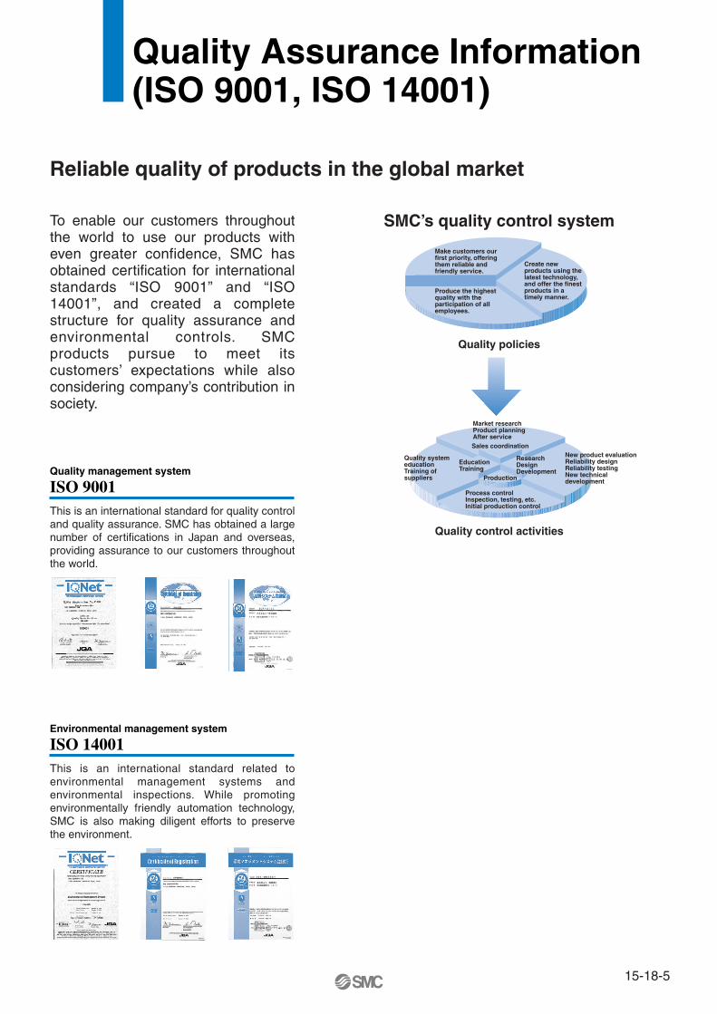
To enable our customers throughout the world to use our products with even greater confidence, SMC has obtained certification for international standards “ISO 9001” and “ISO 14001”, and created a complete structure for quality assurance and environmental controls. SMC products pursue to meet its customers’ expectations while also considering company’s contribution in society.
This is an international standard for quality control and quality assurance. SMC has obtained a large number of certifications in Japan and overseas, providing assurance to our customers throughout the world.
Quality management system
ISO 9001
This is an international standard related to environmental management systems and environmental inspections. While promoting environmentally friendly automation technology, SMC is also making diligent efforts to preserve the environment.
Environmental management system
ISO 14001
Sales coordination
Production
Make customers our first priority, offering them reliable and friendly service.
Market researchProduct planningAfter service
Process controlInspection, testing, etc.Initial production control
Quality system educationTraining of suppliers
New product evaluationReliability designReliability testingNew technical development
EducationTraining
ResearchDesignDevelopment
Produce the highest quality with the participation of all employees.
Create new products using the latest technology, and offer the finest products in a timely manner.
SMC’s quality control system
Quality policies
Quality control activities
15-18-5

CE Mark
SMC Product Conforming to Inter
SMC products complying with EN/ISO, CSA/UL standards are supporting
The CE mark indicates that machines and components meet essential requirements of all the EC Directives applied.It has been obligatory to apply CE marks indicating conformity with EC Directives when machines and components are exported to the member Nations of the EU. Once “A manufacturer himself” declares a product to be safe by means of CE marking (declaration of conformity by manufacturer), free distribution inside the member Nations of the EU is permissible.
� CE MarkSMC provides CE marking to products to which EMC and Low Voltage Directives have been applied, in accordance with CETOP (European hydraulics and pneumatics committee) guide lines.
� As of February 1998, the following 18 countries will be obliged to conform to CE mark legislationIceland, Ireland, United Kingdom, Italy, Austria, Netherlands, Greece, Liechtenstein, Sweden, Spain, Denmark, Germany, Norway, Finland, France, Belgium, Portugal, Luxembourg
� EC Directives and Pneumatic Components• Machinery DirectiveThe Machinery Directive contains essential health and safety requirements for machinery, as applied to industrial machines e.g. machine tools, injection molding machines and automatic machines. Pneumatic equipment is not specified in Machinery Directive. However, the use of SMC products that are certified as conforming to EN Standards, allows customers to simplify preparation work of the Technical Construction File required for a Declaration of Conformity.
• Electromagnetic Compatibility (EMC) DirectiveThe EMC Directive specifies electromagnetic compatibility. Equipment which may generate electromagnetic interference or whose function may be compromised by electromagnetic interference is required to be immune to electromagnetic affects (EMS/immunity) without emitting excessive electromagnetic affects (EMI/emission).
• Low Voltage DirectiveThis directive is applied to products, which operate above 50 VAC to 1000 VAC and 75 VDC to 1500 VDC operating voltage, and require electrical safety measures to be introduced.
• Simple Pressure Vessels DirectiveThis directive is applied to welded vessels whose maximum operating pressure (PS) and volume of vessel (V) exceed 50 bar/L. Such vessels require EC type examination and then CE marking.
15-18-6

http://www.smcworld.com
you to comply with EC directives and CSA/UL standards.
� CSA Standards & UL StandardsUL and CSA standards have been applied in North America (U.S.A. and Canada) symbolizing safety of electric products, and are defined to mainly prevent danger from electric shock or fire, resulting from trouble with electric products. Both UL and CSA standards are acknowledged in North America as the first class certifying body. They have a long experience and ability for issuing product safety certificate. Products approved by CSA or UL standards are accepted in most states and governments beyond question.Since CSA is a test certifying body as the National Recognized Testing Laboratory (NRTL) within the jurisdiction of Occupational Safety and Health Administration (OSHA), SMC was tested for compliance with CSA Standards and UL Standards at the same time and was approved for compliance with the two Standards. The above CSA NRTL/C logo is described on a product label in order to indicate that the product is approved by CSA and UL Standards.
� TSSA (MCCR) Registration Products TSSA is the regulation in Ontario State, Canada. The products that the operating pressure is more than 5 psi (0.03 MPa) and the piping size is bigger than 1 inch. fall into the scope of TSSA regulation.
Products conforming to CE Standard
With CE symbol for simple visual recognition
In this catalog each accredited product series is indicated with a CE mark symbol. However, in some cases, every available models may not meet CE compliance. Please visit our web site for the latest selection of available models with CE mark.
Mark of compliance for CSA
Mark of compliance for CSA/UL
national Standards
15-18-7
SMC Product Conforming to International Standards
America EuropeU.S.A. SMC Corporation of America3011 North Franklin Road Indianapolis, IN 46226, U.S.A.TEL: 317-899-4440 FAX: 317-899-3102
CANADA SMC Pneumatics (Canada) Ltd.6768 Financial Drive Mississauga, Ontario, L5N 7J6 CanadaTEL: 905-812-0400 FAX: 905-812-8686
MEXICO SMC Corporation (Mexico), S.A. DE C.V.Carr. Silao-Trejo K.M. 2.5 S/N, Predio San Jose del DuranzoC.P. 36100, Silao, Gto., MexicoTEL: 472-72-2-55-00 FAX: 472-72-2-59-44/2-59-46
CHILE SMC Pneumatics (Chile) S.A.Av. La Montaña 1,115 km. 16,5 P. Norte ParqueIndustrial Valle Grande, Lampa Santiago, ChileTEL: 02-270-8600 FAX: 02-270-8601
ARGENTINA SMC Argentina S.A.Teodoro Garcia 3860 (1427) Buenos Aires, ArgentinaTEL: 011-4555-5762 FAX: 011-4555-5762
BOLIVIA SMC Pneumatics Bolivia S.R.L.Avenida Beni Numero 4665Santa Cruz de la Sierra-Casilla de Correo 2281, BoliviaTEL: 591-3-3428383 FAX: 591-3-3449900
VENEZUELA SMC Neumatica Venezuela S.A. Apartado 40152, Avenida Nueva Granada, Edificio Wanlac,Local 5, Caracas 1040-A, VenezuelaTEL: 2-632-1310 FAX: 2-632-3871
PERU (Distributor) IMPECO Automatizacion Industrial S.A. AV. Canevaro 752, Lince, Lima, PeruTEL: 1-471-6002 FAX: 1-471-0935
URUGUAY (Distributor) BAKO S.A. Galicia 1650 esq. Gaboto C.P. 11200, Montevideo, UruguayTEL: 2-401-6603 FAX: 2-409-4306
BRAZIL SMC Pneumaticos Do Brasil Ltda.Rua. Dra. Maria Fidelis, nr. 130, Jardim Piraporinha-Diadema-S.P. CEP: 09950-350, BrasilTEL: 11-4051-1177 FAX: 11-4071-6636
COLOMBIA (Distributor) Airmatic Ltda.Calle 18 69-05 Apart. Aereo 081045 Santa Fe de Bogotá, ColombiaTEL: 1-424-9240 FAX: 1-424-9260
U.K. SMC Pneumatics (U.K.) Ltd.Vincent Avenue, Crownhill, Milton Keynes, MK8 0AN, Backinghamshire, U.K.TEL: 01908-563888 FAX: 01908-561185
GERMANY SMC Pneumatik GmbHBoschring 13-15 D-63329 Egelsbach, GermanyTEL: 06103-4020 FAX: 06103-402139
ITALY SMC Italia S.p.A.Via Garibaldi 62 I-20061 Carugate Milano, ItalyTEL: 02-9271365 FAX: 02-9271365
FRANCE SMC Pneumatique S.A.1 Boulevard de Strasbourg, Parc Gustave Eiffel, Bussy Saint Georges, F-77600Marne La Vallee Cedex 3 FranceTEL: 01-64-76-10-00 FAX: 01-64-76-10-10
SWEDEN SMC Pneumatics Sweden ABEkhagsvägen 29-31, S-141 05 Huddinge, SwedenTEL: 08-603-07-00 FAX: 08-603-07-10
SWITZERLAND SMC Pneumatik AGDorfstrasse 7, Postfach 117, CH-8484 Weisslingen, SwitzerlandTEL: 052-396-3131 FAX: 052-396-3191
AUSTRIA SMC Pneumatik GmbH (Austria)Girakstrasse 8, A-2100 Korneuburg, AustriaTEL: 0-2262-6228-0 FAX: 0-2262-62285
SPAIN SMC España, S.A.Zuazobidea 14 Pol. Ind. Júndiz 01015 Vitoria, SpainTEL: 945-184-100 FAX: 945-184-510
IRELAND SMC Pneumatics (Ireland) Ltd.2002 Citywest Business Campus, Naas Road, Saggart, Co. Dublin, IrelandTEL: 01-403-9000 FAX: 01-466-0385
NETHERLANDS (Associated company) SMC Pneumatics BVDe Ruyterkade 120, NL-1011 AB Amsterdam, NetherlandsTEL: 020-5318888 FAX: 020-5318880
GREECE (Distributor) S.Parianopoulos S.A.7, Konstantinoupoleos Street 11855 Athens, GreeceTEL: 01-3426076 FAX: 01-3455578
DENMARK SMC Pneumatik A/SKnudsminde 4 B DK-8300Odder, DenmarkTEL: 70252900 FAX: 70252901
SMC’s Global Service Network
15-18-20
EuropeFINLAND SMC Pneumatics Finland OYPL72, Tiistinniityntie 4, SF-02231 ESP00, FinlandTEL: 09-8595-80 FAX: 09-8595-8595
NORWAY SMC Pneumatics Norway A/SVollsveien 13C, Granfoss Næringspark N-1366 LYSAKER, NorwayTEL: 67-12-90-20 FAX: 67-12-90-21
BELGIUM (Distributor) SMC Pneumatics N.V./S.A.Nijverheidsstraat 20 B-2160 Wommelgem BelguimTEL: 03-355-1464 FAX: 03-355-1466
POLAND SMC Industrial Automation Polska Sp.z.o.o.ul. Konstruktorska 11A, PL-02-673 Warszawa, PolandTEL: 022-548-5085 FAX: 022-548-5087
TURKEY (Distributor) Entek Pnömatik San.ve Tic. Ltd. StiPerpa Tic. Merkezi Kat:11 No.1625 80270 Okmeydani Istanbul, TürkiyeTEL: 0212-221-1512 FAX: 0212-221-1519
RUSSIA SMC Pneumatik LLC.36/40 Sredny prospect V.O. St. Petersburg 199004, RussiaTEL: 812-118-5445 FAX: 812-118-5449
CZECH SMC Industrial Automation CZ s.r.o.Hudcova 78a, CZ-61200 Brno, Czech RepublicTEL: 05-4121-8034 FAX: 05-4121-8034
HUNGARY SMC Hungary Ipari Automatizálási kft.Budafoki ut 107-113 1117 BudapestTEL: 01-371-1343 FAX: 01-371-1344
ROMANIA SMC Romania S.r.l.Str. Frunzei, Nr. 29, Sector 2, Bucharest, RomaniaTEL: 01-3205111 FAX: 01-3261489
SLOVAKIA SMC Priemyselná automatizáciá, s.r.oNova 3, SK-83103 BratislavaTEL: 02-4445-6725 FAX: 02-4445-6028
SLOVENIA SMC Industrijska Avtomatilca d.o.o.Grajski trg 15, SLO- 8360 Zuzemberk, SloveniaTEL: 07388-5240 FAX: 07388-5249
SOUTH AFRICA (Distributor) Hyflo Southern Africa (Pty.) Ltd.P.O.Box 240 Paardeneiland 7420 South AfricaTEL: 021-511-7021 FAX: 021-511-4456
EGYPT (Distributor) Saadani Trading & Ind. Services15 Sebaai Street, Miami 21411 Alexandria, EgyptTEL: 3-548-50-34 FAX: 3-548-50-34
Oceania/AsiaAUSTRALIA SMC Pneumatics (Australia) Pty.Ltd.14-18 Hudson Avenue Castle Hill NSW 2154, AustraliaTEL: 02-9354-8222 FAX: 02-9894-5719
NEW ZEALAND SMC Pneumatics (New Zealand) Ltd.8C Sylvia Park Road Mt.Wellington Auckland, New ZealandTEL: 09-573-7007 FAX: 09-573-7002
TAIWAN SMC Pneumatics (Taiwan) Co.,Ltd.17, Lane 205, Nansan Rd., Sec.2, Luzhu-Hsiang, Taoyuan-Hsien, TAIWANTEL: 03-322-3443 FAX: 03-322-3387
HONG KONG SMC Pneumatics (Hong Kong) Ltd. 29/F, Clifford Centre, 778-784 Cheung, Sha Wan Road, Lai Chi Kok, Kowloon,Hong KongTEL: 2744-0121 FAX: 2785-1314
SINGAPORE SMC Pneumatics (S.E.A.) Pte. Ltd.89 Tuas Avenue 1, Jurong Singapore 639520TEL: 6861-0888 FAX: 6861-1889
PHILIPPINES SHOKETSU SMC CorporationUnit 201 Common Goal Tower, Madrigal Business Park,Ayala Alabang Muntinlupa, PhilippinesTEL: 02-8090565 FAX: 02-8090586
MALAYSIA SMC Pneumatics (S.E.A.) Sdn. Bhd.Lot 36 Jalan Delima1/1, Subang Hi-Tech Industrial Park, Batu 3 40000 Shah AlamSelangor, MalaysiaTEL: 03-56350590 FAX: 03-56350602
SOUTH KOREA SMC Pneumatics Korea Co., Ltd.Woolim e-BIZ Center (Room 1008), 170-5, Guro-Dong, Guro-Gu,Seoul, 152-050, South KoreaTEL: 02-3219-0700 FAX: 02-3219-0702
CHINA SMC (China) Co., Ltd.7 Wan Yuan St. Beijing Economic & Technological Development Zone 100176, China TEL: 010-67882111 FAX: 010-67881837
THAILAND SMC Thailand Ltd.134/6 Moo 5, Tiwanon Road, Bangkadi, Amphur Muang, Patumthani 12000, ThailandTEL: 02-963-7099 FAX: 02-501-2937
INDIA SMC Pneumatics (India) Pvt. Ltd.D-107 to 112, Phase-2, Extension, Noida, Dist. Gautaim Budh Nagar,U.P. 201 305, IndiaTEL: (0120)-4568730 FAX: 0120-4568933
INDONESIA (Distributor) P.T. Riyadi Putera MakmurJalan Hayam Wuruk Komplek Glodok Jaya No. 27-28 Jakarta 11180 IndonesiaTEL: 021-625 5548 FAX: 021-625 5888
PAKISTAN (Distributor) Jubilee CorporationFirst Floor Mercantile Centre, Newton Road Near Boulton Market P.O. Box 6165 Karachi 74000 PakistanTEL: 021-243-9070/8449 FAX: 021-241-4589
ISRAEL (Distributor) Baccara Automation ControlKvutzat Geva 18915 IsraelTEL: 04-653-5960 FAX: 04-653-1445
SAUDI ARABIA (Distributor) Assaggaff Trading Est.P.O. Box 3385 Al-Amir Majed Street, Jeddah-21471, Saudi ArabiaTEL: 02-6761574 FAX: 02-6708173
15-18-21
SMC’s Global Service Network