4 soft matter - princeton universitystonelab/publications/pdfs/from howard... · we report...
TRANSCRIPT

Volum
e4|Num
ber7|2008Soft M
atterPages1329–1540
www.softmatter.org
REVIEW ARTICLEDirkPijperandBenL.FeringaControlofdynamichelicityatthemacro-andsupramolecularlevel
ISSN1744-683X
PAPERGeorgeM.Whitesideset al.InterfacialinstabilitiesinamicrofluidicHele-Shawcell
Soft Matter
1744-683X(2008)4:7;1-H
Volume4|Number7|7July2008|Pages1329–1540
www.rsc.org/shopRegistered Charity Number 207890
Sit back and relax…Online shopping is easy with the RSC
Whether you’re looking for text books, the latest research articles, training courses, conferences or a light read for the commute…online shopping with the RSC couldn’t be easier.
24/7 access: The RSC online shop gives you continuous access to class leading products and services, expertly tailored to cater for your training and educational needs.
Browse and buy: Visit our shop to browse over 750 book titles, subscribe or purchase an individual article in one of our journals, join or renew your RSC membership, or register to attend a conference or training event.
Gift ideas: If you’re looking for gift ideas, look no further. In our online shop you’ll find everything from popular science books like The Age of the Molecule and the inspirational Elegant Solutions from award winning writer, Philip Ball, to our stunning Visual Elements Periodic Table wall chart and jigsaw.
With secure online payment you can shop online with confidence.
The RSC has so much to offer…why not go online today?
1912
0654
a
PAPER www.rsc.org/softmatter | Soft Matter
Interfacial instabilities in a microfluidic Hele-Shaw cell†
Michinao Hashimoto,a Piotr Garstecki,*b Howard A. Stonec and George M. Whitesides*a
Received 15th October 2007, Accepted 14th April 2008
First published as an Advance Article on the web 8th May 2008
DOI: 10.1039/b715867j
This paper describes surfactant-sensitive, dynamic instabilities that occur to aqueous droplets
translating in a continuous flow of hexadecane in a microfluidic Hele-Shaw cell (HSC). A very low
interfacial tension (on the order of 0.01 mN m�1) between water and hexadecane allowed for
deformation of the droplets along the fields of flow and tip-streaming from moving droplets. In the
system of water and hexadecane that we investigated, the use of surfactants in both fluids was necessary
to achieve interfacial tension sufficiently low for the instabilities to occur. The droplets entering the
HSC stretched orthogonally to the main direction of flow into elongated shapes, with aspect ratios
greater than ten to one (width to length). These droplets exhibited two types of instabilities. The first
included elongation of droplets, and Rayleigh–Plateau instabilities in the stretched droplets. Arrays of
these stretched droplets formed three characteristic patterns that depended on the rates of flow of water
and hexadecane. The second was driven by the shear stress exerted on the interface between the two
fluids by the top and bottom boundaries of the HSC; this instability is named a ‘‘shear-driven
instability’’ (SDI). Our observations supported that the SDI—an effect similar to tip-streaming—
resulted from a redistribution of surfactants at the interface between the two fluids.
Introduction
We report experimental observations of flow patterns and
dynamic instabilities of droplets in a microfluidic Hele-Shaw
cell.1 The system comprises a microfluidic flow-focusing (FF)
structure that generates droplets of aqueous solutions in an
organic continuous phase,2–4 and delivers the two phases into
a channel that is typically fifty times wider than it is tall. We
followed convention and called this channel a Hele-Shaw cell
(HSC). The flow entering the HSC is characterized by a pattern
of streamlines that diverges from the centerline to the sides of the
cell. We studied the flow pattern of droplets of water containing
Tween 20 (2% w/w) in a continuous phase of hexadecane
containing Span 80 (3% w/w). With this combination of fluids
and surfactants, the interfacial tension between the two fluids
was extremely low (on the order of 0.01 mN m�1), and the
interface between the two fluids yielded easily to the flow field
defined by the geometry of the channel; droplets elongated into
sausage-like shapes with widths much larger (typically by more
than a factor of ten) than their lengths as they entered the HSC.
These elongated droplets experienced a capillary instability, and
broke up into droplets of nearly circular cross-sections in the
plane of the HSC,5,6 with diameters comparable to the height of
the HSC. The progression of the capillary instability was slowed
by confinement by the boundaries of the HSC.7,8 At low rates of
aDepartment of Chemistry and Chemical Biology, Harvard University, 12Oxford St., Cambridge, MA, 02138, USA. E-mail: [email protected] of Physical Chemistry, Polish Academy of Sciences, Kasprzaka44/52, 01-224 Warsaw, Poland. E-mail: [email protected] of Engineering and Applied Sciences, Harvard University, 29Oxford St., Cambridge, MA, 02138, USA
† Electronic supplementary information (ESI) available: Additionalimages and discussions on formation of patterns, shear-driven instability,and effects of surfactants are presented. See DOI: 10.1039/b715867j
This journal is ª The Royal Society of Chemistry 2008
flow of the two fluids, the elongated droplets flowed downstream
in the form of regular ‘fishbone’ patterns, before breaking up into
smaller drops. As we demonstrate, the shape of these patterns
could be, to some extent, controlled by modifying the shape of
the walls of the HSC.
Over a range of rates of flow of both phases, the droplets
translating in the HSC developed ‘curtains’—wide sheets of
liquid—at their trailing edges, at both the floor and the ceiling of
the HSC. These curtains subsequently evolved into threads, and
the threads broke up into small droplets. The size of these small
droplets was at least an order of magnitude smaller than the
height of the HSC. On the basis of observations made in exper-
iments with different concentrations of surfactants in both the
continuous and the dispersed phase, we believe that this shear-
driven instability (SDI) is critically dependent on the interfacial
tension between the two phases, and on the dynamic effects of
interfacial tension caused by redistribution of surfactants.
Hele-Shaw cell
The term ‘‘Hele-Shaw cell (HSC)’’ refers to a space created by the
gap between two parallel plates.1 This setup has two character-
istics that make it a useful tool with which to analyze multiphase
flows and various interfacial phenomena. First, multiphase flows
in an HSC are easily visualized through the transparent cell.
Second, due to the high ratio of the lateral dimensions to the
height of the cell, many flows can be well approximated by a two-
dimensional description. Such two-dimensional flows in an HSC
obey Darcy’s law; this flow is mathematically equivalent to that
in a porous medium.9 The study of flow in an HSC thus provides
insights into multiphase flows in porous media—a subject that is
important in areas such as geophysics and oil recovery.10,11 We
can construct such a Hele-Shaw cell by separating two trans-
parent plates with narrow spacers that define the aspect ratio of
Soft Matter, 2008, 4, 1403–1413 | 1403
the cell. Alternately, the use of techniques in soft lithography
makes it possible to create such high aspect ratio geometries at
the micron-scale.
Here we investigated flows and interfacial phenomena of
aqueous droplets in an organic fluid using microfluidic versions
of HSCs. Such multiphase, droplet-based systems are common in
microfluidics; examples include systems used for micro-
reactions,12,13 kinetic analyses,14 encapsulations,15,16 syntheses of
colloidal particles,17,18 and crystallization of proteins.19 The use
of surfactants is often necessary for applications of such droplet-
based systems; it is therefore important to understand the
behaviors of droplets and the influence of surfactants at length-
scales relevant to on-chip applications.
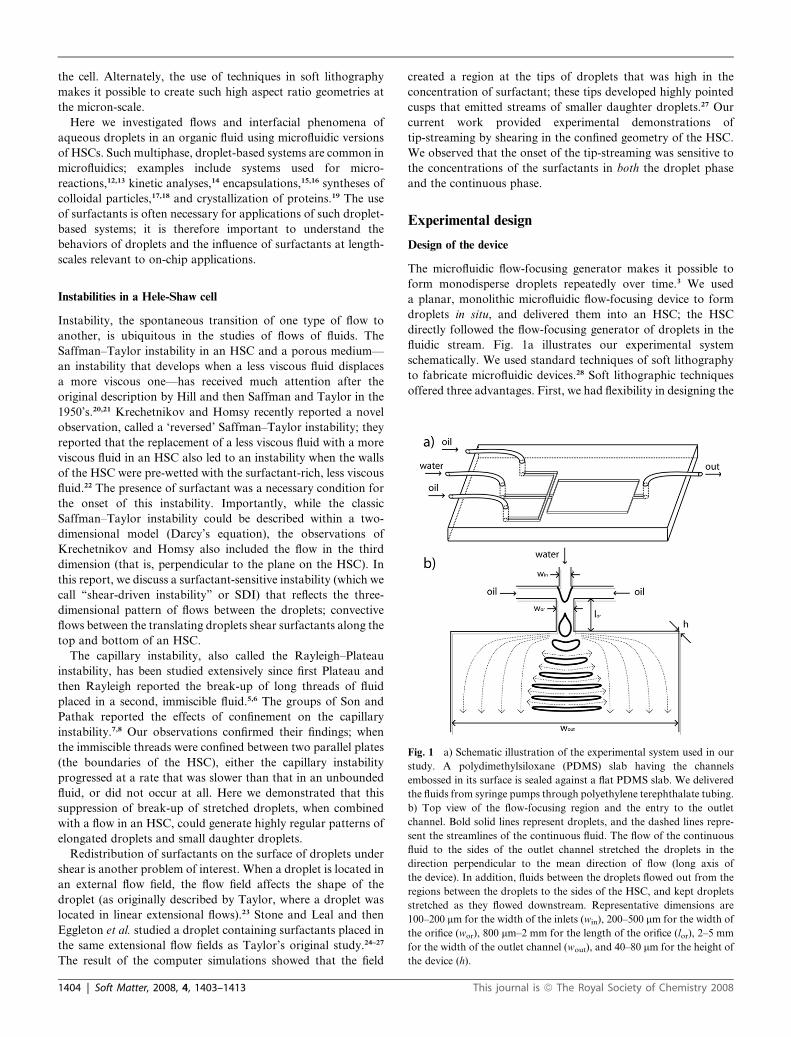
Fig. 1 a) Schematic illustration of the experimental system used in our
study. A polydimethylsiloxane (PDMS) slab having the channels
embossed in its surface is sealed against a flat PDMS slab. We delivered
the fluids from syringe pumps through polyethylene terephthalate tubing.
b) Top view of the flow-focusing region and the entry to the outlet
channel. Bold solid lines represent droplets, and the dashed lines repre-
sent the streamlines of the continuous fluid. The flow of the continuous
fluid to the sides of the outlet channel stretched the droplets in the
direction perpendicular to the mean direction of flow (long axis of
the device). In addition, fluids between the droplets flowed out from the
regions between the droplets to the sides of the HSC, and kept droplets
stretched as they flowed downstream. Representative dimensions are
100–200 mm for the width of the inlets (win), 200–500 mm for the width of
the orifice (wor), 800 mm–2 mm for the length of the orifice (lor), 2–5 mm
for the width of the outlet channel (wout), and 40–80 mm for the height of
the device (h).
Instabilities in a Hele-Shaw cell
Instability, the spontaneous transition of one type of flow to
another, is ubiquitous in the studies of flows of fluids. The
Saffman–Taylor instability in an HSC and a porous medium—
an instability that develops when a less viscous fluid displaces
a more viscous one—has received much attention after the
original description by Hill and then Saffman and Taylor in the
1950’s.20,21 Krechetnikov and Homsy recently reported a novel
observation, called a ‘reversed’ Saffman–Taylor instability; they
reported that the replacement of a less viscous fluid with a more
viscous fluid in an HSC also led to an instability when the walls
of the HSC were pre-wetted with the surfactant-rich, less viscous
fluid.22 The presence of surfactant was a necessary condition for
the onset of this instability. Importantly, while the classic
Saffman–Taylor instability could be described within a two-
dimensional model (Darcy’s equation), the observations of
Krechetnikov and Homsy also included the flow in the third
dimension (that is, perpendicular to the plane on the HSC). In
this report, we discuss a surfactant-sensitive instability (which we
call ‘‘shear-driven instability’’ or SDI) that reflects the three-
dimensional pattern of flows between the droplets; convective
flows between the translating droplets shear surfactants along the
top and bottom of an HSC.
The capillary instability, also called the Rayleigh–Plateau
instability, has been studied extensively since first Plateau and
then Rayleigh reported the break-up of long threads of fluid
placed in a second, immiscible fluid.5,6 The groups of Son and
Pathak reported the effects of confinement on the capillary
instability.7,8 Our observations confirmed their findings; when
the immiscible threads were confined between two parallel plates
(the boundaries of the HSC), either the capillary instability
progressed at a rate that was slower than that in an unbounded
fluid, or did not occur at all. Here we demonstrated that this
suppression of break-up of stretched droplets, when combined
with a flow in an HSC, could generate highly regular patterns of
elongated droplets and small daughter droplets.
Redistribution of surfactants on the surface of droplets under
shear is another problem of interest. When a droplet is located in
an external flow field, the flow field affects the shape of the
droplet (as originally described by Taylor, where a droplet was
located in linear extensional flows).23 Stone and Leal and then
Eggleton et al. studied a droplet containing surfactants placed in
the same extensional flow fields as Taylor’s original study.24–27
The result of the computer simulations showed that the field
1404 | Soft Matter, 2008, 4, 1403–1413
created a region at the tips of droplets that was high in the
concentration of surfactant; these tips developed highly pointed
cusps that emitted streams of smaller daughter droplets.27 Our
current work provided experimental demonstrations of
tip-streaming by shearing in the confined geometry of the HSC.
We observed that the onset of the tip-streaming was sensitive to
the concentrations of the surfactants in both the droplet phase
and the continuous phase.
Experimental design
Design of the device
The microfluidic flow-focusing generator makes it possible to
form monodisperse droplets repeatedly over time.3 We used
a planar, monolithic microfluidic flow-focusing device to form
droplets in situ, and delivered them into an HSC; the HSC
directly followed the flow-focusing generator of droplets in the
fluidic stream. Fig. 1a illustrates our experimental system
schematically. We used standard techniques of soft lithography
to fabricate microfluidic devices.28 Soft lithographic techniques
offered three advantages. First, we had flexibility in designing the
This journal is ª The Royal Society of Chemistry 2008

Fig. 2 Optical micrographs (top view) of the orifice channel illustrating
the process by which aqueous droplets formed in the continuous phase of
hexadecane, translated in the orifice, and entered the HSC. The set of
fluids was (water, Tween 20, 2%; hexadecane, Span 80, 3%). Note that
shear forces pulled triangular sheets from translating droplets at the
locations where the droplets contacted the top and bottom walls of
the channel; Fig. 5a provides a schematic representation of three-
dimensional shapes of the droplet.
shape of the channel, especially the shape of the HSC. Second, we
could control the aspect ratio of the HSC relatively easily during
the fabrication of the master. We fabricated the HSC with a wide
(2 to 5 mm) and short (height 50 to 100 mm) outlet channel.
Third, replica molding made it easy to prepare multiple identical
devices; the experiments required testing a range of different
fluids. When we tested a different set of surfactants, for example,
we had to use a device that was never exposed to the previous set
of fluids. Replica molding made it possible to prepare multiple,
unused devices that were indistinguishable; the techniques were
therefore ideal for the experiments described here.
Choice of fluids
We used hexadecane as the continuous phase and water as the
dispersed phase. The continuous phase must prevent: i) the
coalescence of the dispersed phase, and ii) the wetting of the wall
of the PDMS channel by the dispersed phase. A solution of Span
80 in hexadecane meets these two criteria (when water is the
dispersed phase). Span 80 is an inexpensive, commercially
available surfactant; the molecule is an ester of oleic acid that
dissolves only in hexadecane, not in water. The use of fluoro-
carbon or silicone oil, with commercially available surfactants,
caused aqueous droplets to coalesce in the HSC when the
droplets contacted one another. We chose water as the dispersed
phase (i.e. droplets). Water is one of the most common liquids
used in microfluidics. We studied the effects of additives in the
dispersed phase, such as surfactants and other small molecules
that changed the physical properties (especially the interfacial
free energy) of the droplets, on the behavior of the flowing
droplets in the channel. We tested three surfactants (Tween 20,
cetyltrimethylammonium bromide, and sodium dodecyl sulfate)
that dissolved only in water, not in hexadecane. Our observations
indicated that, with the set of fluids and surfactants that we
investigated in this manuscript, surfactants must be present in
both phases in order to achieve interfacial tensions sufficiently
low for droplets to undergo the observed deformations and
instabilities during their flow in the HSC in our system.
Results and discussion
Notations
Unless otherwise noted, we use the following conventions to
describe the system throughout the manuscript. The volumetric
rates of flow of the dispersed phase (Qd) and the continuous
phase (Qc) are given in square parentheses, denoted as [Qd
(mL s�1), Qc (mL s�1)]. The types and concentrations of the
surfactants in each phase are given in curved parentheses,
denoted as (dispersed fluid, type of surfactant, concentration
percentage by weight (w/w); continuous fluid, type of surfactant,
concentration percentage by weight (w/w)).
Formation of the droplets
Many recent studies reported formation of droplets3,29,30 and
bubbles2,4 in microfluidic flow-focusing devices. Here we only
sketch the process that forms the droplets. The flow-focusing
region comprises three inlet channels—two side channels for the
continuous, organic phase, and a central channel for the
This journal is ª The Royal Society of Chemistry 2008
dispersed, aqueous phase. The pressure drop across the orifice
causes the aqueous thread to advance downstream, to break and
emit a droplet, and to retract back. This cycle repeats periodi-
cally, and the system generates nearly monodisperse droplets; the
coefficient of variation of the diameter of the droplets generated
in our current design (defined as the ratio of the standard devi-
ation and the average of diameter) was 5.5% (n ¼ 30). A droplet
travels downstream in the orifice and reaches the outlet channel.
Fig. 2 illustrates the formation and translation of droplets in the
flow-focusing geometry, and at the entrance of the HSC.
For the rates of flows we examined, the system produced
droplets when the ratio of the rates of flow of the continuous
phase (hexadecane; Qc) to the dispersed phase (water; Qd) is �1 <
Qc/Qd < �6. When Qc/Qd was much greater than 6, the pressure
created by hexadecane pushed water back into the inlet, and the
entire device filled with hexadecane. When Qc/Qd was less than 1,
water flowed through the orifice without break-up; these patterns
of flow formed a laminar co-flow of water and hexadecane.
Further increase in the rate of the flow of water (Qc/Qd � 1)
caused water to flow into the inlets of hexadecane. Fig. 3 shows
the phase diagram of the different experimental observations as
we varied the two rates of flow (i.e. Qc and Qd); the lines for
Qc/Qd ¼ 1 and Qc/Qd ¼ 6 are indicated.
Formation of patterns in an HSC
As the two fluids left the orifice, the streamlines of the continuous
phase diverged from the centerline to the sides of the HSC. A
single-phase fluid flowing in this configuration would develop
streamlines similar to a two-dimensional source flow because the
HSC was significantly wider (2 to 5 mm) than the orifice (200 to
500 mm). The streamlines that diverged to the sides of the HSC
applied shear stresses on the droplets. As a result, the droplets
stretched into elongated shapes characterized by a high aspect
ratio (width to length). The continuous phase also flowed out to
Soft Matter, 2008, 4, 1403–1413 | 1405
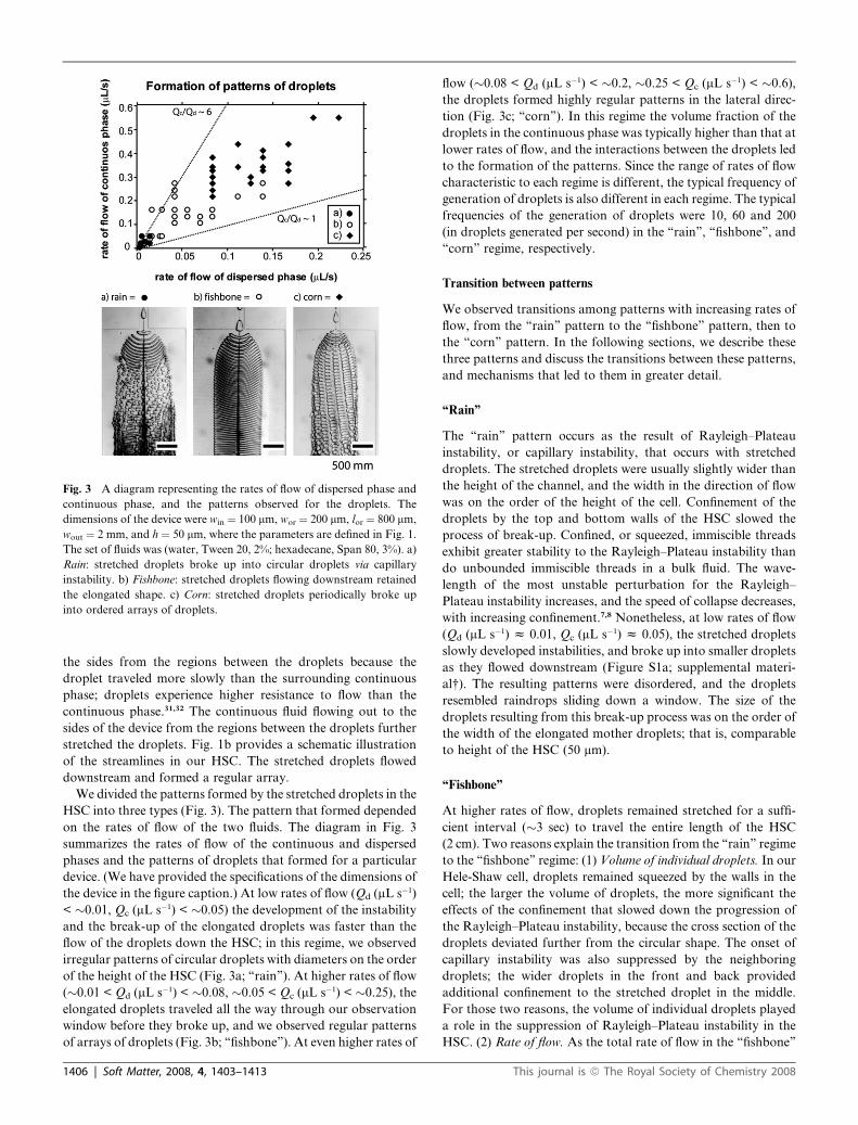
Fig. 3 A diagram representing the rates of flow of dispersed phase and
continuous phase, and the patterns observed for the droplets. The
dimensions of the device were win ¼ 100 mm, wor ¼ 200 mm, lor ¼ 800 mm,
wout ¼ 2 mm, and h ¼ 50 mm, where the parameters are defined in Fig. 1.
The set of fluids was (water, Tween 20, 2%; hexadecane, Span 80, 3%). a)
Rain: stretched droplets broke up into circular droplets via capillary
instability. b) Fishbone: stretched droplets flowing downstream retained
the elongated shape. c) Corn: stretched droplets periodically broke up
into ordered arrays of droplets.
the sides from the regions between the droplets because the
droplet traveled more slowly than the surrounding continuous
phase; droplets experience higher resistance to flow than the
continuous phase.31,32 The continuous fluid flowing out to the
sides of the device from the regions between the droplets further
stretched the droplets. Fig. 1b provides a schematic illustration
of the streamlines in our HSC. The stretched droplets flowed
downstream and formed a regular array.
We divided the patterns formed by the stretched droplets in the
HSC into three types (Fig. 3). The pattern that formed depended
on the rates of flow of the two fluids. The diagram in Fig. 3
summarizes the rates of flow of the continuous and dispersed
phases and the patterns of droplets that formed for a particular
device. (We have provided the specifications of the dimensions of
the device in the figure caption.) At low rates of flow (Qd (mL s�1)
< �0.01, Qc (mL s�1) < �0.05) the development of the instability
and the break-up of the elongated droplets was faster than the
flow of the droplets down the HSC; in this regime, we observed
irregular patterns of circular droplets with diameters on the order
of the height of the HSC (Fig. 3a; ‘‘rain’’). At higher rates of flow
(�0.01 < Qd (mL s�1) < �0.08, �0.05 < Qc (mL s�1) < �0.25), the
elongated droplets traveled all the way through our observation
window before they broke up, and we observed regular patterns
of arrays of droplets (Fig. 3b; ‘‘fishbone’’). At even higher rates of
1406 | Soft Matter, 2008, 4, 1403–1413
flow (�0.08 < Qd (mL s�1) < �0.2, �0.25 < Qc (mL s�1) < �0.6),
the droplets formed highly regular patterns in the lateral direc-
tion (Fig. 3c; ‘‘corn’’). In this regime the volume fraction of the
droplets in the continuous phase was typically higher than that at
lower rates of flow, and the interactions between the droplets led
to the formation of the patterns. Since the range of rates of flow
characteristic to each regime is different, the typical frequency of
generation of droplets is also different in each regime. The typical
frequencies of the generation of droplets were 10, 60 and 200
(in droplets generated per second) in the ‘‘rain’’, ‘‘fishbone’’, and
‘‘corn’’ regime, respectively.
Transition between patterns
We observed transitions among patterns with increasing rates of
flow, from the ‘‘rain’’ pattern to the ‘‘fishbone’’ pattern, then to
the ‘‘corn’’ pattern. In the following sections, we describe these
three patterns and discuss the transitions between these patterns,
and mechanisms that led to them in greater detail.
‘‘Rain’’
The ‘‘rain’’ pattern occurs as the result of Rayleigh–Plateau
instability, or capillary instability, that occurs with stretched
droplets. The stretched droplets were usually slightly wider than
the height of the channel, and the width in the direction of flow
was on the order of the height of the cell. Confinement of the
droplets by the top and bottom walls of the HSC slowed the
process of break-up. Confined, or squeezed, immiscible threads
exhibit greater stability to the Rayleigh–Plateau instability than
do unbounded immiscible threads in a bulk fluid. The wave-
length of the most unstable perturbation for the Rayleigh–
Plateau instability increases, and the speed of collapse decreases,
with increasing confinement.7,8 Nonetheless, at low rates of flow
(Qd (mL s�1) z 0.01, Qc (mL s�1) z 0.05), the stretched droplets
slowly developed instabilities, and broke up into smaller droplets
as they flowed downstream (Figure S1a; supplemental materi-
al†). The resulting patterns were disordered, and the droplets
resembled raindrops sliding down a window. The size of the
droplets resulting from this break-up process was on the order of
the width of the elongated mother droplets; that is, comparable
to height of the HSC (50 mm).
‘‘Fishbone’’
At higher rates of flow, droplets remained stretched for a suffi-
cient interval (�3 sec) to travel the entire length of the HSC
(2 cm). Two reasons explain the transition from the ‘‘rain’’ regime
to the ‘‘fishbone’’ regime: (1) Volume of individual droplets. In our
Hele-Shaw cell, droplets remained squeezed by the walls in the
cell; the larger the volume of droplets, the more significant the
effects of the confinement that slowed down the progression of
the Rayleigh–Plateau instability, because the cross section of the
droplets deviated further from the circular shape. The onset of
capillary instability was also suppressed by the neighboring
droplets; the wider droplets in the front and back provided
additional confinement to the stretched droplet in the middle.
For those two reasons, the volume of individual droplets played
a role in the suppression of Rayleigh–Plateau instability in the
HSC. (2) Rate of flow. As the total rate of flow in the ‘‘fishbone’’
This journal is ª The Royal Society of Chemistry 2008
regime was �10 times higher than that in the ‘‘rain’’ regime, the
droplets remained in the HSC for a much shorter time. As the
result, droplets could exit the channel before the instability
became observable. In a straight HSC, the droplets straightened
out as they flowed down the channel. We demonstrated that the
structure of patterns of droplets could, to some extent, be
modulated through changes in the shape of the HSC (Figure S2;
supplemental material†).
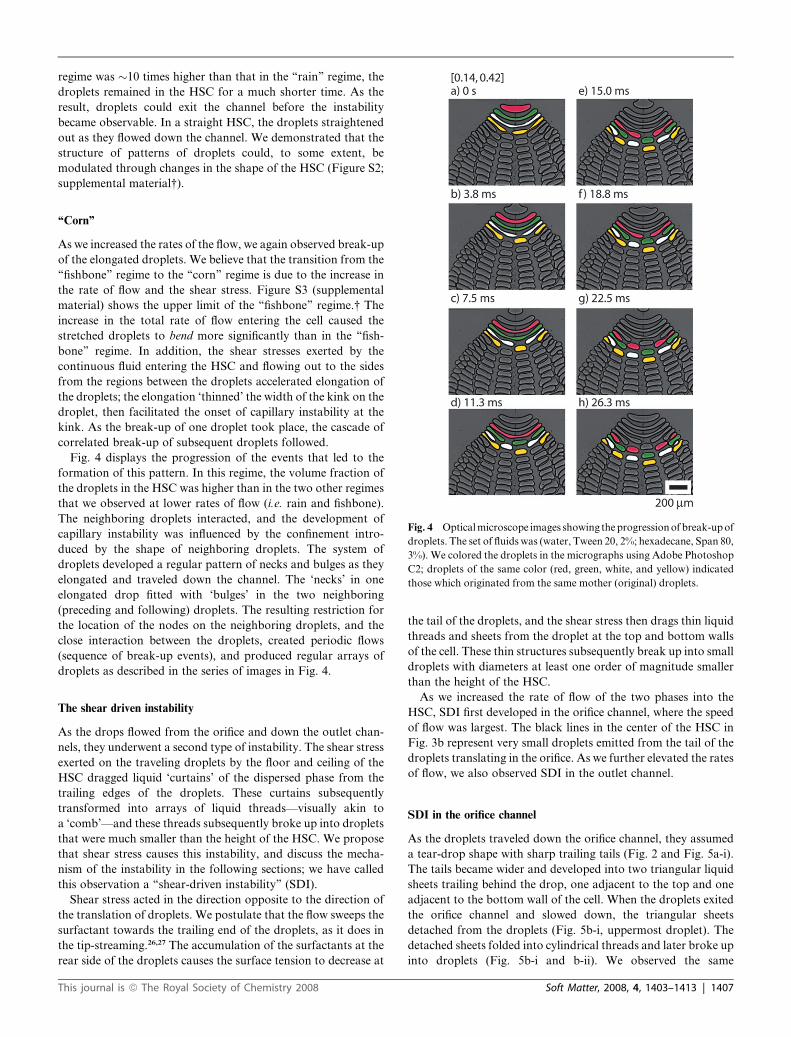
Fig. 4 Optical microscope images showing the progression of break-up of
droplets. The set of fluids was (water, Tween 20, 2%; hexadecane, Span 80,
3%). We colored the droplets in the micrographs using Adobe Photoshop
C2; droplets of the same color (red, green, white, and yellow) indicated
those which originated from the same mother (original) droplets.
‘‘Corn’’
As we increased the rates of the flow, we again observed break-up
of the elongated droplets. We believe that the transition from the
‘‘fishbone’’ regime to the ‘‘corn’’ regime is due to the increase in
the rate of flow and the shear stress. Figure S3 (supplemental
material) shows the upper limit of the ‘‘fishbone’’ regime.† The
increase in the total rate of flow entering the cell caused the
stretched droplets to bend more significantly than in the ‘‘fish-
bone’’ regime. In addition, the shear stresses exerted by the
continuous fluid entering the HSC and flowing out to the sides
from the regions between the droplets accelerated elongation of
the droplets; the elongation ‘thinned’ the width of the kink on the
droplet, then facilitated the onset of capillary instability at the
kink. As the break-up of one droplet took place, the cascade of
correlated break-up of subsequent droplets followed.
Fig. 4 displays the progression of the events that led to the
formation of this pattern. In this regime, the volume fraction of
the droplets in the HSC was higher than in the two other regimes
that we observed at lower rates of flow (i.e. rain and fishbone).
The neighboring droplets interacted, and the development of
capillary instability was influenced by the confinement intro-
duced by the shape of neighboring droplets. The system of
droplets developed a regular pattern of necks and bulges as they
elongated and traveled down the channel. The ‘necks’ in one
elongated drop fitted with ‘bulges’ in the two neighboring
(preceding and following) droplets. The resulting restriction for
the location of the nodes on the neighboring droplets, and the
close interaction between the droplets, created periodic flows
(sequence of break-up events), and produced regular arrays of
droplets as described in the series of images in Fig. 4.
The shear driven instability
As the drops flowed from the orifice and down the outlet chan-
nels, they underwent a second type of instability. The shear stress
exerted on the traveling droplets by the floor and ceiling of the
HSC dragged liquid ‘curtains’ of the dispersed phase from the
trailing edges of the droplets. These curtains subsequently
transformed into arrays of liquid threads—visually akin to
a ‘comb’—and these threads subsequently broke up into droplets
that were much smaller than the height of the HSC. We propose
that shear stress causes this instability, and discuss the mecha-
nism of the instability in the following sections; we have called
this observation a ‘‘shear-driven instability’’ (SDI).
Shear stress acted in the direction opposite to the direction of
the translation of droplets. We postulate that the flow sweeps the
surfactant towards the trailing end of the droplets, as it does in
the tip-streaming.26,27 The accumulation of the surfactants at the
rear side of the droplets causes the surface tension to decrease at
This journal is ª The Royal Society of Chemistry 2008
the tail of the droplets, and the shear stress then drags thin liquid
threads and sheets from the droplet at the top and bottom walls
of the cell. These thin structures subsequently break up into small
droplets with diameters at least one order of magnitude smaller
than the height of the HSC.
As we increased the rate of flow of the two phases into the
HSC, SDI first developed in the orifice channel, where the speed
of flow was largest. The black lines in the center of the HSC in
Fig. 3b represent very small droplets emitted from the tail of the
droplets translating in the orifice. As we further elevated the rates
of flow, we also observed SDI in the outlet channel.
SDI in the orifice channel
As the droplets traveled down the orifice channel, they assumed
a tear-drop shape with sharp trailing tails (Fig. 2 and Fig. 5a-i).
The tails became wider and developed into two triangular liquid
sheets trailing behind the drop, one adjacent to the top and one
adjacent to the bottom wall of the cell. When the droplets exited
the orifice channel and slowed down, the triangular sheets
detached from the droplets (Fig. 5b-i, uppermost droplet). The
detached sheets folded into cylindrical threads and later broke up
into droplets (Fig. 5b-i and b-ii). We observed the same
Soft Matter, 2008, 4, 1403–1413 | 1407

Fig. 5 a) Schematic illustration of the geometry of the droplets under-
going the shear-driven instabilities in the HSC. i) Shape of the droplet in
the orifice channel and ii) portion of the stretched droplet in the outlet
channel. For clarity, we sketched only the bottom plate of the HSC, and
omitted the top plate. b) Optical micrographs of the HSC illustrating
shear-driven instability (SDI) occurring near the ceiling and floor of the
HSC (wout ¼ 5 mm). The set of fluids was (water, Tween 20, 2%;
hexadecane, Span 80, 3%). i) The triangular liquid sheets pulled behind
the droplet in the orifice channel detached at the entrance to the outlet
channel. ii) The detached sheets folded into threads and broke into
smaller droplets. iii) and iv) As the droplets stretched in the outlet
channel, they developed a comb-like structure. The sheets pulled behind
the drop developed an array of liquid threads (inset iii), which subse-
quently separated into smaller drops (inset iv). Note in iv) that the comb
structure formed on both the ceiling and the floor of the cell.
instability occurring in the circular droplets formed via the
capillary instability (i.e. ‘‘rain’’ pattern in Fig. 3a).
SDI in the HSC
The stretched droplets also underwent a similar instability. Two
liquid sheets were pulled along the top and bottom boundaries.
We observed a periodic shedding of the liquid sheets that
subsequently broke into small droplets (Fig. 5b-iii and b-iv).
Fig. 5a illustrates this instability schematically. Multiple trian-
gular sheets were pulled from the translating droplets, forming
a structure visually similar to a comb, and each triangular sheet
went through the same geometrical transformations as those that
occurred with tails of circular droplets. We observed that the
further were the stretched droplets from the centerline of the
channel, the earlier the tails started to emerge (Fig. 5b-iii). These
observations reflected the redistribution of the surfactants caused
by the flow of the continuous phase between the elongated
droplets; the flow between the droplets brought the surfactants
along the interface toward both ends of the elongated droplets
(Fig. 1). As a result, the lateral extremes of the droplets should be
expected to have higher concentration of the surfactants at the
interfaces than their centers, and the onset of SDI at both ends
was enhanced.
The stretched droplets showed higher stability to SDI than
circular droplets (Figure S1b; supplemental material†). We
believe this stabilization was due to the flow pattern around the
1408 | Soft Matter, 2008, 4, 1403–1413
droplets; when circular droplets traveled, the external flow at
both sides of the droplets also facilitated the redistribution of the
surfactants to the back of the droplets. The redistribution of the
surfactants was thus enhanced more for circular droplets than for
stretched droplets. For stretched droplets, a larger number of
tails evolved at the ends of the stretched droplets than at the
center of the droplet. This observation also suggests that the
external flow around the stretched droplets enhanced the number
of occurrences of SDI. We provide more details about the
development of SDI in the supplemental section (Figure S4;
supplemental material).†
Redistribution of surfactants
We suggest possible effects of surfactants in our system, and
propose flow patterns that led to the SDI. We believe that the
primary cause of the SDI was redistribution of the surfactants
around the translating droplets. Accumulation of the surfactants
toward the back of the droplet lowered the interfacial tension
between water and oil; the decrease in the interfacial tension
allowed the shear stresses exerted by the continuous phase
recirculating between the droplets to stretch the dispersed phase
into thin water films along the top and bottom boundaries of the
HSC. These effects are similar to the phenomenon of tip-
streaming,27 and we note that the observed behaviors could not
be explained on the basis of capillary numbers calculated with the
static values of interfacial tension.
Flow inside and between droplets and redistribution of surfactant
We propose that the flow pattern inside the traveling drops, and
in between two neighboring drops, caused redistribution of
surfactant towards the trailing edges of the droplets.33–36 Such
redistribution of surfactants led to the onset of the SDI. Fig. 6
schematically illustrates the flow patterns inside the droplets. In
the reference frame traveling with the droplets, the fluid inside
the droplet traced convection rolls with positive velocity (in the
mean direction of flow) half way between the plates of HSC, and
with negative velocity at the walls of HSC. The continuous fluid
behind the droplet traced similar patterns with positive speeds in
between the plates, and with liquid recirculating back upstream
at the top and bottom walls. Note that depending on the
viscosities of the two fluids, the actual flow patterns may be more
complicated with small regions of closed streamlines near the
front and the back of the droplets.
The flow inside the droplets sheared surfactants from the top
and bottom interfaces of the droplet towards the trailing ends.
The recirculation of the continuous phase from the center of the
walls of the HSC sheared surfactant towards the rear top and
bottom edges of the droplet. The concentration of surfactant
increased, and the interfacial tension decreased at the trailing
edge. As a result, the interface yielded to the shear stress exerted
by the walls of the HSC, resulting in the onset of SDI. This is the
basic scenario commonly described as tip streaming,27 though
here it occurs along a trailing edge. Experiments performed
without surfactants in the dispersed phase confirmed the above
reasoning: we did not observe the SDI in these experiments
(Fig. 6a). We discuss the role of surfactants in the observed
instabilities below.
This journal is ª The Royal Society of Chemistry 2008
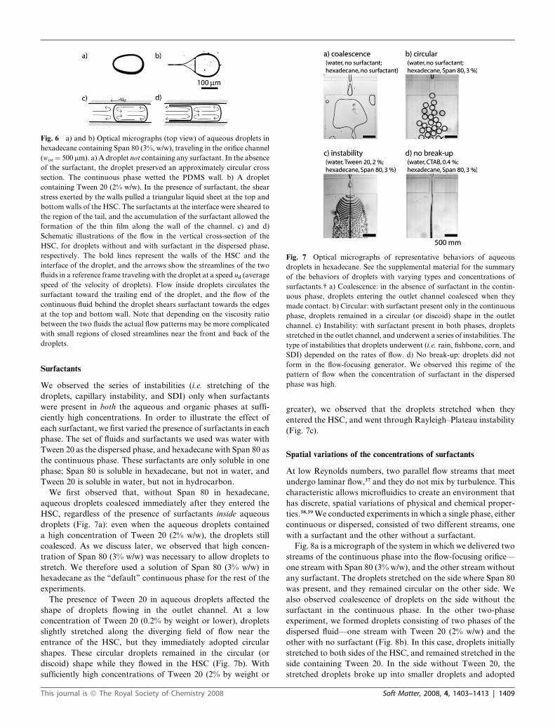
Fig. 6 a) and b) Optical micrographs (top view) of aqueous droplets in
hexadecane containing Span 80 (3%, w/w), traveling in the orifice channel
(wor ¼ 500 mm). a) A droplet not containing any surfactant. In the absence
of the surfactant, the droplet preserved an approximately circular cross
section. The continuous phase wetted the PDMS wall. b) A droplet
containing Tween 20 (2% w/w). In the presence of surfactant, the shear
stress exerted by the walls pulled a triangular liquid sheet at the top and
bottom walls of the HSC. The surfactants at the interface were sheared to
the region of the tail, and the accumulation of the surfactant allowed the
formation of the thin film along the wall of the channel. c) and d)
Schematic illustrations of the flow in the vertical cross-section of the
HSC, for droplets without and with surfactant in the dispersed phase,
respectively. The bold lines represent the walls of the HSC and the
interface of the droplet, and the arrows show the streamlines of the two
fluids in a reference frame traveling with the droplet at a speed ud (average
speed of the velocity of droplets). Flow inside droplets circulates the
surfactant toward the trailing end of the droplet, and the flow of the
continuous fluid behind the droplet shears surfactant towards the edges
at the top and bottom wall. Note that depending on the viscosity ratio
between the two fluids the actual flow patterns may be more complicated
with small regions of closed streamlines near the front and back of the
droplets.
Fig. 7 Optical micrographs of representative behaviors of aqueous
droplets in hexadecane. See the supplemental material for the summary
of the behaviors of droplets with varying types and concentrations of
surfactants.† a) Coalescence: in the absence of surfactant in the contin-
uous phase, droplets entering the outlet channel coalesced when they
made contact. b) Circular: with surfactant present only in the continuous
phase, droplets remained in a circular (or discoid) shape in the outlet
channel. c) Instability: with surfactant present in both phases, droplets
stretched in the outlet channel, and underwent a series of instabilities. The
type of instabilities that droplets underwent (i.e. rain, fishbone, corn, and
SDI) depended on the rates of flow. d) No break-up: droplets did not
form in the flow-focusing generator. We observed this regime of the
pattern of flow when the concentration of surfactant in the dispersed
phase was high.
Surfactants
We observed the series of instabilities (i.e. stretching of the
droplets, capillary instability, and SDI) only when surfactants
were present in both the aqueous and organic phases at suffi-
ciently high concentrations. In order to illustrate the effect of
each surfactant, we first varied the presence of surfactants in each
phase. The set of fluids and surfactants we used was water with
Tween 20 as the dispersed phase, and hexadecane with Span 80 as
the continuous phase. These surfactants are only soluble in one
phase; Span 80 is soluble in hexadecane, but not in water, and
Tween 20 is soluble in water, but not in hydrocarbon.
We first observed that, without Span 80 in hexadecane,
aqueous droplets coalesced immediately after they entered the
HSC, regardless of the presence of surfactants inside aqueous
droplets (Fig. 7a): even when the aqueous droplets contained
a high concentration of Tween 20 (2% w/w), the droplets still
coalesced. As we discuss later, we observed that high concen-
tration of Span 80 (3% w/w) was necessary to allow droplets to
stretch. We therefore used a solution of Span 80 (3% w/w) in
hexadecane as the ‘‘default’’ continuous phase for the rest of the
experiments.
The presence of Tween 20 in aqueous droplets affected the
shape of droplets flowing in the outlet channel. At a low
concentration of Tween 20 (0.2% by weight or lower), droplets
slightly stretched along the diverging field of flow near the
entrance of the HSC, but they immediately adopted circular
shapes. These circular droplets remained in the circular (or
discoid) shape while they flowed in the HSC (Fig. 7b). With
sufficiently high concentrations of Tween 20 (2% by weight or
This journal is ª The Royal Society of Chemistry 2008
greater), we observed that the droplets stretched when they
entered the HSC, and went through Rayleigh–Plateau instability
(Fig. 7c).
Spatial variations of the concentrations of surfactants
At low Reynolds numbers, two parallel flow streams that meet
undergo laminar flow,37 and they do not mix by turbulence. This
characteristic allows microfluidics to create an environment that
has discrete, spatial variations of physical and chemical proper-
ties.38,39 We conducted experiments in which a single phase, either
continuous or dispersed, consisted of two different streams, one
with a surfactant and the other without a surfactant.
Fig. 8a is a micrograph of the system in which we delivered two
streams of the continuous phase into the flow-focusing orifice—
one stream with Span 80 (3% w/w), and the other stream without
any surfactant. The droplets stretched on the side where Span 80
was present, and they remained circular on the other side. We
also observed coalescence of droplets on the side without the
surfactant in the continuous phase. In the other two-phase
experiment, we formed droplets consisting of two phases of the
dispersed fluid—one stream with Tween 20 (2% w/w) and the
other with no surfactant (Fig. 8b). In this case, droplets initially
stretched to both sides of the HSC, and remained stretched in the
side containing Tween 20. In the side without Tween 20, the
stretched droplets broke up into smaller droplets and adopted
Soft Matter, 2008, 4, 1403–1413 | 1409
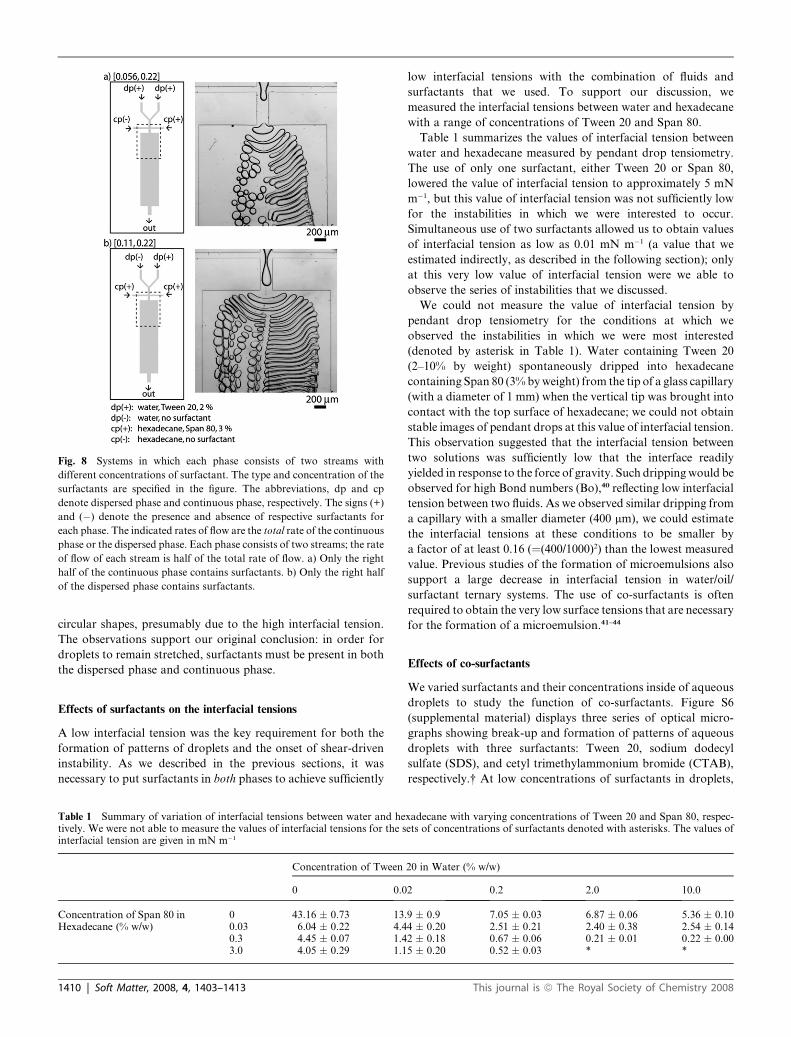
Fig. 8 Systems in which each phase consists of two streams with
different concentrations of surfactant. The type and concentration of the
surfactants are specified in the figure. The abbreviations, dp and cp
denote dispersed phase and continuous phase, respectively. The signs (+)
and (�) denote the presence and absence of respective surfactants for
each phase. The indicated rates of flow are the total rate of the continuous
phase or the dispersed phase. Each phase consists of two streams; the rate
of flow of each stream is half of the total rate of flow. a) Only the right
half of the continuous phase contains surfactants. b) Only the right half
of the dispersed phase contains surfactants.
circular shapes, presumably due to the high interfacial tension.
The observations support our original conclusion: in order for
droplets to remain stretched, surfactants must be present in both
the dispersed phase and continuous phase.
Effects of surfactants on the interfacial tensions
A low interfacial tension was the key requirement for both the
formation of patterns of droplets and the onset of shear-driven
instability. As we described in the previous sections, it was
necessary to put surfactants in both phases to achieve sufficiently
Table 1 Summary of variation of interfacial tensions between water and hetively. We were not able to measure the values of interfacial tensions for the sinterfacial tension are given in mN m�1
Concentration of Tween
0 0.0
Concentration of Span 80 inHexadecane (% w/w)
0 43.16 � 0.73 13.0.03 6.04 � 0.22 4.40.3 4.45 � 0.07 1.43.0 4.05 � 0.29 1.1
1410 | Soft Matter, 2008, 4, 1403–1413
low interfacial tensions with the combination of fluids and
surfactants that we used. To support our discussion, we
measured the interfacial tensions between water and hexadecane
with a range of concentrations of Tween 20 and Span 80.
Table 1 summarizes the values of interfacial tension between
water and hexadecane measured by pendant drop tensiometry.
The use of only one surfactant, either Tween 20 or Span 80,
lowered the value of interfacial tension to approximately 5 mN
m�1, but this value of interfacial tension was not sufficiently low
for the instabilities in which we were interested to occur.
Simultaneous use of two surfactants allowed us to obtain values
of interfacial tension as low as 0.01 mN m�1 (a value that we
estimated indirectly, as described in the following section); only
at this very low value of interfacial tension were we able to
observe the series of instabilities that we discussed.
We could not measure the value of interfacial tension by
pendant drop tensiometry for the conditions at which we
observed the instabilities in which we were most interested
(denoted by asterisk in Table 1). Water containing Tween 20
(2–10% by weight) spontaneously dripped into hexadecane
containing Span 80 (3% by weight) from the tip of a glass capillary
(with a diameter of 1 mm) when the vertical tip was brought into
contact with the top surface of hexadecane; we could not obtain
stable images of pendant drops at this value of interfacial tension.
This observation suggested that the interfacial tension between
two solutions was sufficiently low that the interface readily
yielded in response to the force of gravity. Such dripping would be
observed for high Bond numbers (Bo),40 reflecting low interfacial
tension between two fluids. As we observed similar dripping from
a capillary with a smaller diameter (400 mm), we could estimate
the interfacial tensions at these conditions to be smaller by
a factor of at least 0.16 (¼(400/1000)2) than the lowest measured
value. Previous studies of the formation of microemulsions also
support a large decrease in interfacial tension in water/oil/
surfactant ternary systems. The use of co-surfactants is often
required to obtain the very low surface tensions that are necessary
for the formation of a microemulsion.41–44
Effects of co-surfactants
We varied surfactants and their concentrations inside of aqueous
droplets to study the function of co-surfactants. Figure S6
(supplemental material) displays three series of optical micro-
graphs showing break-up and formation of patterns of aqueous
droplets with three surfactants: Tween 20, sodium dodecyl
sulfate (SDS), and cetyl trimethylammonium bromide (CTAB),
respectively.† At low concentrations of surfactants in droplets,
xadecane with varying concentrations of Tween 20 and Span 80, respec-ets of concentrations of surfactants denoted with asterisks. The values of
20 in Water (% w/w)
2 0.2 2.0 10.0
9 � 0.9 7.05 � 0.03 6.87 � 0.06 5.36 � 0.104 � 0.20 2.51 � 0.21 2.40 � 0.38 2.54 � 0.142 � 0.18 0.67 � 0.06 0.21 � 0.01 0.22 � 0.005 � 0.20 0.52 � 0.03 * *
This journal is ª The Royal Society of Chemistry 2008

we obtained spherical droplets. In this regime, the size of the
droplets decreased as the concentration of surfactants increased.
The lower the interfacial tension became, the more readily the
interface yielded to the shear force exerted by the continuous
streams. As a result, for a given set of rates of flow, we obtained
small droplets with the higher concentration of the surfactant. As
we increased the concentration of surfactants further, we
observed a series of instabilities. We note that the concentrations
of Tween 20 at which we observed the series of instabilities
corresponded to those at which the interfacial tensions were too
low to be measured by pendant drop tensiometry (Table 1). We
believe that the difference in ‘‘fishbone’’ and ‘‘rain’’ patterns in
the series of Tween 20 (2% and 10%, respectively) also reflected
the size of individual droplets. The effects of confinement that
slow down the progress of the capillary instability were less
significant for smaller droplets. Here, the use of mixed surfac-
tants with sufficiently high concentrations was again critical for
the development of instabilities.
We also studied the effects of non-amphipathic, small mole-
cules: ethanol, glycerol, and trimethylamine n-oxide (TMAO) as
co-surfactants in aqueous droplets. None of the systems showed
instabilities of the sorts of interest in this paper (Figure S7;
supplemental material†).
Capillary numbers
The lowest volumetric rate of flow at which we observed SDI in
the 5 mm wide outlet channel was on the order of Q z 0.01 mL
s�1. We estimated the capillary number as Ca ¼ mu/g ¼ mQ/whg
z 5 � 10�3. Here, the parameters were the viscosity of the
continuous fluid, mz 10�3 Pa s, the width of the HSC, w¼ 5 mm,
the height of the channel, h¼ 40 mm, and the interfacial tension g
z 0.01 mN m�1 ¼ 10�5 N m�1. This value of the capillary number
was comparable to the values reported by Kopfsill and Homsy
(Ca z 10�3) and Park et al. (Ca z 10�2) for the formation of
sharp trailing ends on bubbles and droplets translating in an
HSC.45,46 The low value of the capillary number suggests that the
effects of surface tension dominate the shear stress exerted by the
walls of the HSC. We would not expect, however, that sharply
pointed threads or liquid sheets could be drawn from the trans-
lating drops in flows characterized by these low values of Ca. We
therefore believe that capillary numbers based on the static
values of interfacial tensions do not explain the observed
behaviors of instabilities and changes in the shape of the drop-
lets. We speculate that the accumulation of surfactants at the rear
side of the droplets by extensional flows and convection between
the droplets lowered the interfacial tension more than it would in
the static cases, and allowed the formation of cusps.
Conclusions
This paper describes the flow of aqueous droplets traveling in
a microfluidic Hele-Shaw cell when surfactants significantly
influence the behaviors of droplets. This system displayed a range
of distinct flow patterns. The combination of flow fields and
shear stresses exerted by the continuous fluid caused droplets to
elongate perpendicularly to the primary direction of the flow in
an HSC; these elongated droplets formed highly regular arrays,
and underwent a series of instabilities. The confinement of the
This journal is ª The Royal Society of Chemistry 2008
droplets by the bottom and top walls of the HSC suppressed the
onset of capillary instabilities; as a result, the droplets stayed
elongated while they flowed downstream, forming a regular
array of droplets. Another type of regular pattern arose at high
rates of flow; the interactions between the elongated droplets
induced lateral regularities in the events leading to the break-up
of elongated droplets, and consequently in the location of the
smaller droplets that formed.
Shear-driven instability
Over a wide range of rates of flow of the two fluids, the droplets
developed a shear-driven instability (SDI). This process
comprised a cascade of geometrical transformations of the
dispersed fluid: from droplets, into thin sheets, to fingers, and
finally into small droplets. These small droplets had dimensions
that were at least an order of magnitude smaller than the height
of the HSC. Based on our observations, we postulate that the
SDI resulted from dynamic surface tension effects caused by
redistribution of the surfactant along the interface, analogous to
tip streaming on isolated droplets in shear and extensional flows.
Shear stress played a role at the interface of the liquids due to
convective flows both inside the primary droplets (dispersed
phase) and in between them (continuous phase). Our microfluidic
HSC, combined with a flow-focusing device, offered a convenient
experimental setup for studies of multiphase flows and interfacial
phenomena such as capillary instabilities and tip streaming.
Surfactant/co-surfactant system
Droplet-based microfluidic systems involving a single surfactant
have been extensively studied, and they are applied in a variety of
fields.47–49 This paper has discussed simultaneous use of two
surfactants in droplet-based microfluidic systems. We observed
that the interfacial tension between the two fluids was sufficiently
low (reduced by a factor greater than 200) to allow extreme
elongation of droplets and the formation of trailing films, only
when both phases contained surfactants. Extensional flows in
these systems could readily modify the shape of the droplets; we
demonstrated that a spherical droplet could be stretched to an
elongated shape with an aspect ratio (width to length) on the
order of 100. While synthesis of non-spherical objects18,50,51 in
microfluidic platforms has been demonstrated, our observation
may provide an alternative route to engineer the shape of
materials in microfluidics.
Pattern formations by extensional flows
The most interesting aspect of this work is the observation of
a number of instabilities of different origin and the associated
mechanisms. The dynamics led to the spontaneous formation of
regular patterns. The regularities resulted from: i) extensional
flows defined by the geometry of the channel, and ii) extensional
flows defined by the other droplets. For example, both the
diverging flows at the entrance of the HSC and the flows between
two neighboring droplets were necessary to create the ‘‘fishbone’’
pattern. The ‘‘corn’’ pattern was a more striking example of the
formation of regular patterns resulting from the interaction
among neighboring droplets. The break-up of one stretched
droplet changed the extensional field of flow, and triggered the
Soft Matter, 2008, 4, 1403–1413 | 1411
break-up of the next droplets; these two processes alternated, and
led to the formation of a regular, complex pattern of droplets. We
could control, or at least affect, the pattern that formed with the
variation of a limited number of experimentally accessible
parameters (i.e. rates of flow). In addition to previous demon-
strations of pattern formations in out-of-equilibrium systems,52–56
our current results once again exhibited the potential of micro-
fluidic systems as a convenient testbed for studying formation of
regular patterns in dissipative systems; such patterns are often
otherwise difficult to obtain.
Experimental section
Fabrication of microfluidic devices
We prepared the microfluidic devices using soft lithography.57
We sealed the polydimethylsiloxane (PDMS) bas relief molds
with the channels patterned in them against flat slabs of PDMS;
the two pieces of PDMS were plasma-oxidized for one minute,
and the substrates were brought into contact to form an
irreversible seal.28 To ensure that the surfaces of the PDMS
channels were hydrophobic after sealing, we incubated the sealed
microfluidic devices at 120 �C for at least 24 hours after plasma
oxidation and sealing.28 We delivered the two immiscible
phases into the microfluidic chip using polyethylene tere-
phthalate tubing (Becton, Dickinson and Company) from
digitally controlled syringe pumps (Harvard Apparatus, model
PhD2000).
Fluids
The dispersed phase was water (Millipore, deionized, m ¼ 0.890
mPa s at 25 �C) containing Tween 20 (Polysorbate 80, 0.1–10%
w/w, Aldrich, a nonionic surfactant). The continuous phase was
hexadecane (Sigma-Aldrich, m ¼ 3.032 mPa s at 25 �C)
containing Span 80 (sorbitan oleate, 3% w/w, Aldrich, a nonionic
surfactant).58 Unless stated otherwise, we performed experiments
with the ‘default’ concentrations of surfactants: 2% (w/w) Tween
20 in the aqueous phase and 3% (w/w) Span 80 in the continuous
fluid. Other surfactants and additives used in the experiment
were cetyltrimethylammonium bromide (�99%, Sigma), sodium
dodecyl sulfate (J.T.Baker), and trimethylamine N-oxide (98%,
Aldrich), ethanol (Pharmaco-AAPER) and glycerol (Gibco
BRL); they were dissolved in water (Millipore, deionized) on the
benchtop to prepare the samples.
Imaging
A upright Leica DMRX microscope and a set of still (Nicon
Digital Camera DXM 1200) and fast-video (Phantom V7)
cameras visualized and recorded the behaviors of the system. We
used Adobe Photoshop C2, Adobe Illustrator C2, and Adobe
Premiere 7.0 for the analysis of images and the preparation of
the figures. The colors of the images (Fig. 4) were added using
Adobe Photoshop C2.
Measurement of interfacial tension
We used a pendant drop tensiometry method to measure the
interfacial tension between water and hexadecane.59 A digital
1412 | Soft Matter, 2008, 4, 1403–1413
camera (Nicon Digital Camera DXM 1200) took still images of
pendant drops from glass capillaries (VWR International). We
used Adobe Photoshop C3 to enhance the contrast between the
droplet and the background of the digital images. We analyzed
the images using home-made software developed by the Stone
group (Harvard University, School of Engineering and Applied
Sciences).
Acknowledgements
We thank W. D. Ristenpart and E. A. van Nierop for help with
the pendant drop tensiometer and related image analysis soft-
ware. This work was supported by the US Department of Energy
under award DE-FG02-OOER45852. Shared facilities funded by
NSF under MRSEC award DMR-0213805 were utilized for
some of the work. M.H. acknowledges the provision of travel
funds from NSF under NSEC award PHY-0117795. P.G.
acknowledges financial support from the Foundation for Polish
Science and from the Ministry of Science and Higher Education
of Poland for the years 2006–2009.
References
1 H. S. Hele-Shaw, Trans. R. Inst. Nav. Archit., London, 1898, 40, 218.2 A. M. Ganan-Calvo and J. M. Gordillo, Phys. Rev. Lett., 2001, 87.3 S. L. Anna, N. Bontoux and H. A. Stone, Appl. Phys. Lett., 2003, 82,
364–366.4 P. Garstecki, I. Gitlin, W. DiLuzio, G. M. Whitesides, E. Kumacheva
and H. A. Stone, Appl. Phys. Lett., 2004, 85, 2649–2651.5 J. Plateau, Statique Experimentale et Theorique des Liquides Soumisaux Seules Forces Moleculaires, Gauthier-Villars, Paris, 1873.
6 L. Rayleigh, Proc. R. Soc. London, 1879, 29, 71.7 Y. Son, N. S. Martys, J. G. Hagedorn and K. B. Migler,Macromolecules, 2003, 36, 5825–5833.
8 J. A. Pathak and K. B. Migler, Langmuir, 2003, 19, 8667–8674.9 K. V. McCloud and J. V. Maher, Phys. Rep., 1995, 260, 139–185.
10 K. C. Taylor and H. A. Nasr-El-Din, J. Pet. Sci. Eng., 1998, 19, 265–280.
11 M. J. Blunt, M. D. Jackson, M. Piri and P. H. Valvatne, Adv. WaterResour., 2002, 25, 1069–1089.
12 J. R. Burns and C. Ramshaw, Lab Chip, 2001, 1, 10–15.13 E. M. Chan, A. P. Alivisatos and R. A. Mathies, J. Am. Chem. Soc.,
2005, 127, 13854–13861.14 H. Song and R. F. Ismagilov, J. Am. Chem. Soc., 2003, 125, 14613–
14619.15 K. Martin, T. Henkel, V. Baier, A. Grodrian, T. Schon, M. Roth,
J. M. Kohler and J. Metze, Lab Chip, 2003, 3, 202–207.16 S. Sugiura, T. Oda, Y. Izumida, Y. Aoyagi, M. Satake, A. Ochiai,
N. Ohkohchi and M. Nakajima, Biomaterials, 2005, 26, 3327–3331.17 S. A. Khan, A. Gunther, M. A. Schmidt and K. F. Jensen, Langmuir,
2004, 20, 8604–8611.18 S. Q. Xu, Z. H. Nie, M. Seo, P. Lewis, E. Kumacheva, H. A. Stone,
P. Garstecki, D. B. Weibel, I. Gitlin and G. M. Whitesides, Angew.Chem., Int. Ed., 2005, 44, 724–728.
19 B. Zheng, L. S. Roach and R. F. Ismagilov, J. Am. Chem. Soc., 2003,125, 11170–11171.
20 S. Hill, Chem. Eng. Sci., 1952, 1, 247–253.21 P. G. Saffman and G. Taylor, Proc. R. Soc. London, Ser. A, 1958, 245,
312–329.22 R. Krechetnikov and G. M. Homsy, J. Fluid Mech., 2004, 509, 103–
124.23 G. I. Taylor, Proc. R. Soc. London, Ser. A, 1934, 146, 0501–0523.24 H. A. Stone and L. G. Leal, J. Colloid Interface Sci., 1989, 133, 340–
347.25 H. A. Stone and L. G. Leal, J. Fluid Mech., 1990, 220, 161–186.26 C. D. Eggleton, Y. P. Pawar and K. J. Stebe, J. Fluid Mech., 1999,
385, 79–99.27 C. D. Eggleton, T. M. Tsai and K. J. Stebe, Phys. Rev. Lett., 2001,
8704.
This journal is ª The Royal Society of Chemistry 2008

28 D. C. Duffy, J. C. McDonald, O. J. A. Schueller andG. M. Whitesides, Anal. Chem., 1998, 70, 4974–4984.
29 T. Nisisako, T. Torii and T. Higuchi, Lab Chip, 2002, 2, 24–26.30 Q. Y. Xu and M. Nakajima, Appl. Phys. Lett., 2004, 85, 3726–3728.31 H. Wong, C. J. Radke and S. Morris, J. FluidMech., 1995, 292, 71–94.32 H. Wong, C. J. Radke and S. Morris, J. FluidMech., 1995, 292, 95–110.33 S. S. Sadhal and R. E. Johnson, J. Fluid Mech., 1983, 126, 237–250.34 K. J. Stebe, S. Y. Lin and C. Maldarelli, Phys. Fluids A, 1991, 3, 3–20.35 F. Wassmuth, W. G. Laidlaw and D. A. Coombe, Phys. Fluids A,
1993, 5, 1533–1548.36 K. J. Stebe and C. Maldarelli, J. Colloid Interface Sci., 1994, 163, 177–
189.37 D. J. Tritton, Physical Fluid Dynamics, Oxford University Press,
Oxford, 1988.38 X. Y. Jiang, Q. B. Xu, S. K. W. Dertinger, A. D. Stroock, T. M. Fu
and G. M. Whitesides, Anal. Chem., 2005, 77, 2338–2347.39 E. M. Lucchetta, J. H. Lee, L. A. Fu, N. H. Patel and R. F. Ismagilov,
Nature, 2005, 434, 1134–1138.40 Bond number (Bo) is defined as Bo ¼ rgL2/g, where r is the density of
the fluid, g is the acceleration due to gravity, L is the characteristiclength scale of the system, and g is the interfacial tension. Bondnumber is a measure of importance of the gravitational forcerelative to the force by the interfacial tension.
41 P. G. de Gennes and C. Taupin, J. Phys. Chem., 1982, 86, 2294–2304.42 I. Szleifer, D. Kramer, A. Benshaul, D. Roux and W. M. Gelbart,
Phys. Rev. Lett., 1988, 60, 1966–1969.43 B. Farago, D. Richter, J. S. Huang, S. A. Safran and S. T. Milner,
Phys. Rev. Lett., 1990, 65, 3348–3351.
This journal is ª The Royal Society of Chemistry 2008
44 R. Nagarajan and E. Ruckenstein, Langmuir, 2000, 16, 6400–6415.45 A. R. Kopfsill and G. M. Homsy, Phys. Fluids, 1988, 31, 18–26.46 C. W. Park, S. R. K. Maruvada and D. Y. Yoon, Phys. Fluids, 1994,
6, 3267–3275.47 P. Garstecki, A. M. Ganan-Calvo and G. M. Whitesides, Bull. Pol.
Acad. Sci., 2006, 53, 361–372.48 H. Song, D. L. Chen and R. F. Ismagilov, Angew. Chem., Int. Ed.,
2006, 45, 7336–7356.49 A. Gunther and K. F. Jensen, Lab Chip, 2006, 6, 1487–1503.50 A. B. Subramaniam, M. Abkarian, L. Mahadevan and H. A. Stone,
Nature, 2005, 438, 930–930.51 D. Dendukuri, D. C. Pregibon, J. Collins, T. A. Hatton and
P. S. Doyle, Nat. Mater., 2006, 5, 365–369.52 T. Thorsen, R. W. Roberts, F. H. Arnold and S. R. Quake, Phys. Rev.
Lett., 2001, 86, 4163–4166.53 J. P. Raven, P. Marmottant and F. Graner, Eur. Phys. J. B, 2006, 51,
137–143.54 T. Beatus, T. Tlusty and R. Bar-Ziv, Nat. Phys., 2006, 2, 743–748.55 P. Garstecki and G. M. Whitesides, Phys. Rev. Lett., 2006, 97,
024503.56 M. Hashimoto, P. Garstecki and G. M. Whitesides, Small, 2007, 3,
1792–1802.57 Y. N. Xia and G. M. Whitesides, Annu. Rev. Mater. Sci., 1998, 28,
153–184.58 D. R. Lide, Handbook of Chemistry and Physics, CRC Press, Inc.,
77th edn, 1996.59 Y. Rotenberg, L. Boruvka and A. W. Neumann, J. Colloid Interface
Sci., 1983, 93, 169–183.
Soft Matter, 2008, 4, 1403–1413 | 1413