4 project description 4.1 project...
TRANSCRIPT
� �
4 PROJECT DESCRIPTION
4.1 Project Description
The proposed MOST fuel depot with a storage capacity of 15 000 tons of MOGAS and
10 000 tons Gasoil on a plot of land of the extent of 19 794 m2at Mer Rouge will involve
the following.
· Erection of the dike area with appropriate bund walls around each tank to contain
any accidental oil spills from the tanks.
· Construction, installation and commissioning of all associated works related to the
following. � 3 MOGAS vertical storage tanks, each having a capacity of 5 000 tons. � 2 Gasoil vertical 5 000 tons storage tanks.
· Installation of the following pipelines. � A pipeline of 55 m long from the oil jetty manifold to a reception manifold of the
proposed depot. � A pipeline of 54m long from the proposed terminal to the Indian Oil Terminal. � A 2.0 km long pipeline from the proposed depot to Vivo-Energy Terminal. � A pipeline of 2.1 km long connecting the Total Oil depot to this proposed
terminal. � A 2.4 km long pipeline from the proposed terminal to Engen Petroleum oil depot.
· Installation of a pumping station fitted with 5 pumps (1 spare).
· Construction of the following buildings. � Office building of a floor area of 65 m2. � Two gate posts. � Electrical & maintenance building of a floor area of 25 m2.
· Provision of potable water, electricity & telecommunication supply systems.
· Provision of the following � Incoming & outgoing accesses. � Appropriate firefighting system comprising of a fire station of 108 m2, peripheral
fire access roadway around the proposed oil farm, and fire wall of 15 m long and
associated firefighting resources. � Oil-water separator and associated piping systems.

� �
� Domestic sewage disposal system for the office block. � CCTV, Instrumentation & Control systems. � Safety & security measures as per international & Mauritius Ports Authority
guidelines. � Proper lighting system for the proposed oil farm. � Effective storm water drainage system. � Fencing along the site boundary lines.
A proposed layout plan of the oil farm is enclosed in this report as Annex D1. It is to
be noted that this layout plan had been submitted to the Mauritius Port
Authority, which has given its no-objection subject to take into consideration the
findings and recommendations of the risk assessment and alignment of the
present and future pipelines. This is evidenced by a copy of the letter issued by the
MPA dated the 17 July 2014 and referenced as 58/2/112, which is enclosed in this
EIA report as Annex D2.
4.2 THE DIKE AREA
The dike area will be designed to ensure the containment of any accidental oil spills
from the storage tanks. The design of the dike area shall comply with the most
stringent of the applicable standards/norms/regulations enclosed in Annex A2 of this
report.
The dike area will consist of:
· Concrete bund and intermediate walls
· Concrete floor.
· Concrete foundations to be designed according to the geotechnical survey report.
· Crossing of pipes within and around the dike area.
· Low point connection within the dike area for storm run-off/oil spillage washings to
the oil-water separator.
· Appropriate impermeable membrane at some specific locations to avoid any
leakage.

� �
The design of the dike was based on the most stringent international
standards/norms/Regulations listed in Annex A2. Table 4.1 compares these
international standards for height of bund wall as well as the intermediate walls, and
the minimum capacity of dike.
Table 4.1: Comparison of standards for height of bund wall as well as the
intermediate bund wall, and the minimum required dike capacity
LAYOUT CONSTRAINT
TOTAL INDIAN OIL ENGEN VIVO
(RAEDHL-Regulations
of OISD-STD-
118
(SANS 10089-1:2008)
(PTS 20.158B)
DEP 80.00.10.11-
Gen)
9/11/1972 & 19/11/1975)
Minimal height of bund wall
1 m. - §312.114
1 m - §7.1.1 (c)
Maximal height of bund wall
3 m. - §313.3 2 m - §7.1.1
(c)
1,8 m.
§ 4.5.2.1 (e) p. 24
Minimal intermediate bund walls height
0,7 m. 312.113
0,6 m mini - 7.1.3 (a)
0,5 m.
0,6 m mini -
4.2 § 4.5.2.1 (h)
p. 24
Dike minimum capacity
100% of more important
ou 50 % of totality
100% of more important
- § 4.6.3 (b)
p.23
100% of more important
- Table 4.3
Distance between bund wall and boundary of property
3 m. mini - Figure 1 p.20
30 m . Table
4.2
As illustrated in the proposed oil farm layout plan (Annex D1), a bund wall of 2.5 m
high surrounding the 3 MOGAS tanks 01, 02 & 03 will be provided to contain any spill
or leak from the these tanks. The total surface area of the bund will be 4656 m2 and
with a height of 2.5 m, the total volume of the dike for the 3 MOGAS tanks will be
11640 m3, representing 51 % of the total volume of the tanks or 154% of the biggest
tank. In between the 3 MOGAs tanks, there will be 2 intermediate walls of 0.7 m high
each.
It can also be seen in the oil farm layout plan (Annex D1) that the bund wall
surrounding the two Gasoil tanks will be 2.5 m high and an intermediate wall of 0.7 m
in between. The total bund surface area will be 3715 m2 and with a height of 2.5 m, the
total volume of the dike of the Gasoil tanks will be 9287.5 m3, representing 73 % of
total tank volumes or 145% of the biggest tank.
� �
The dike volume complies with the RAEDHL: Règles ‘aménagement et d’exploitation des
depots d’ hydrocarbures liquids (Arrêtés du 9 Novembre 1972 et 9 Novembre 1975 de la
règlementation française) regulations which specifies a minimum of 50% of the total
capacity of the tanks or 100% of the biggest tank. The proposed dike enclosure will be
structurally designed to be able to contain the complete contents of the largest tank in
the dike in case of any spill.
The height of the bund wall of 2.5 m complies with the RAEDHL: Règles ‘aménagement
et d’exploitation des depots d’hydrocarbures liquids (Arrêtés du 9 Novembre 1972 et 9
Novembre 1975 de la règlementation française) regulation which specifies that the
height of the bund wall should be between 1.0 and 3.0 m. The height of the
intermediate bund wall also complies with the RAEDHL regulation. This regulation is
the most stringent of all others norms, standards and regulations as shown in Table
4.1.
Dike enclosure area (inside area of the dike) shall be also impervious to prevent any
leakage. The dike and the enclosures will be inspected for cracks, visible damage etc.
every six months and after every major repair in the tanks / dikes so as to keep it
impervious.
Piping through dike wall, if any, shall be properly sealed to make dyke impervious.
4.3 THE OIL TANKS
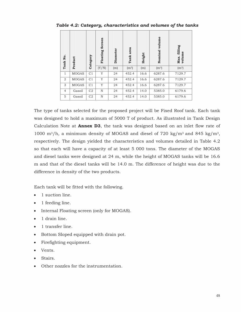
Table 4.2 details the category, characteristics and volumes of the 5 vertical storage
tanks that will be installed.
� �
Table 4.2: Category, characteristics and volumes of the tanks
Tan
k N
o.
Pro
duct
Cate
gory
Flo
ati
ng S
cre
en
Dia
mete
r
Tan
k a
rea
Heig
ht
Nom
inal
volu
me
Max.
fillin
g
volu
me
(Y/N) (m) (m2) (m) (m3) (m3)
1 MOGAS C1 Y 24 452.4 16.6 6287.6 7129.7
2 MOGAS C1 Y 24 452.4 16.6 6287.6 7129.7
3 MOGAS C1 Y 24 452.4 16.6 6287.6 7129.7
4 Gasoil C2 N 24 452.4 14.0 5385.0 6179.6
5 Gasoil C2 N 24 452.4 14.0 5385.0 6179.6
The type of tanks selected for the proposed project will be Fixed Roof tank. Each tank
was designed to hold a maximum of 5000 T of product. As illustrated in Tank Design
Calculation Note at Annex D3, the tank was designed based on an inlet flow rate of
1000 m3/h, a minimum density of MOGAS and diesel of 720 kg/m3 and 845 kg/m3,
respectively. The design yielded the characteristics and volumes detailed in Table 4.2
so that each will have a capacity of at least 5 000 tons. The diameter of the MOGAS
and diesel tanks were designed at 24 m, while the height of MOGAS tanks will be 16.6
m and that of the diesel tanks will be 14.0 m. The difference of height was due to the
difference in density of the two products.
Each tank will be fitted with the following.
· 1 suction line.
· 1 feeding line.
· Internal Floating screen (only for MOGAS).
· 1 drain line.
· 1 transfer line.
· Bottom Sloped equipped with drain pot.
· Firefighting equipment.
· Vents.
· Stairs.
· Other nozzles for the instrumentation.

� �
The MOGAS tank details are illustrated in Annex D4, which shows the stairs leading
to the roof and the handrail at the top of the roof as well as the nozzles and other
necessary accessories.
The diesel tanks details are illustrated in Annex D5. The difference between the
MOGAS and diesel tanks will be that the former will be fitted with an internal floating
screen, which is required to minimise loss of the MOGAS, which is highly volatile, via
hydrocarbon vapour.
The vertical storage tanks were designed and will be constructed and installed to meet
compliance with the standards/norms/regulations listed in Annex A2. The most
stringent standards/norms/regulations will be applied, as far as practicable and
subject to site constraints.
The siting of the tanks within the proposed plot of land was based on the
standards/norms/regulations listed in Annex A2, which are detailed in Table 4.3.
The distance between tanks within the same dike will be 12.5 m and this complies with
the most stringent standard, i.e the VIVO (Shell) DEP 80.00.10.11 – Layout of Onshore
Facilities, which specifies a minimum distance between tanks in the same dike area of
12.0 m (0.5D).
The distance between tanks in different dike area will be 19.2 m and this is in
accordance of the standard, i.e the RAEDHL: Règles ‘aménagement et d’exploitation des
depots d’hydrocarbures liquids (Arrêtés du 9 Novembre 1972 et 9 Novembre 1975 de la
règlementation française) regulation which requires a minimum distance of 19.2 m. It is
to be noted that the most stringent norm for that distance is 30 m as per the Indian Oil
Standard - OISD-STD-118. However, due to site constraint, this cannot be applied.
The distance between a tank and the bund wall will be 8.4 m, and that complies with
VIVO (Shell) DEP 80.00.10.11 – Layout of Onshore Facilities, which specifies a minimum
distance between tanks in the same dike area of 8.4 m.

� �
Table 4.3: Siting of the tanks within the proposed plot of land based on
international standards/norms/Regulations
LAYOUT CONSTRAINT
TOTAL INDIAN OIL ENGEN VIVO
(RAEDHL-Regulations
of OISD-STD-
118
(SANS 10089-1:2008)
(PTS 20.158B)
DEP 80.00.10.11-
Gen)
9/11/1972 & 19/11/1975)
Distance between tanks in same dike – MOGAS
D/4 - §314.31
(D=d)/4 - Table 4
1/6 (D+d) - Table 1
0,3d of larger-
appendix
12,5kWm² - 4.11 p.24
6 m. 12 m. 8 m. 03.05.04 -
7,2m With mini 0,5 D-Table 4.2
12,5 m.
Distance between tanks in same dike – DIESEL
D/4 - §314.31
(D=d)/4 - Table 4
1/6 (D+d) - Table 1
0,5d of larger-
appendix
12,5kWm² - 4.11 p.24
6 m. 12 m. 8 m. 03.05.05 -
12m With mini 0,5 D-Table 4.2
12,5 m.
Distance between tanks in different dike
0,8 D - §314.41
1/6 (D+d) -
Table 1
12,5kWm² - 4.11 p.24
19,2 m. Mini 30 m. -
§ 7.1.1(e) 8 m.
13m - figure 03.05.02
Avek mini 0,5 D-Table 4.2
12,5 m.
Minimal distance between tank shell and bund wall
3 m. - §313.4
H/2 - §7.1.4 (c)
1,5 m. mini - 0,5 Height
Tank - Table 4.2
7 m.
§ 4.5.2.1 (g) p. 24
8,4 m.
Distance between shell tank and buildings
5kWm² - 4.11
p.24
1/6 D -
Figure 1 p.21
15m - appendix 03.05.04
1,5 D with mini of 60 m.
Table 4.2
Distance between shell tank and boundary of property
10 m. with zone type 1
§ 204.1
0, 5 D with mini 20m.
Table 3
0,5 D - Table 2
15m - appendix 03.05.04
The distance between a tank and the office block or any other building like the on-site
fire station will be more than 50 m. Hence, it complies with the minimum distance of
15 m as stipulated by the Engen standard – PTS 20.158B – Petronal Technical
Standards – Sites and Layouts.
The minimum distance between a tank and plot boundary line will be 20 m, hence
complying with the Engen standard – PTS 20.158B – Petronas Technical Standards –
Sites and Layouts, which specifies a minimum distance of 15 m.

� �
The minimum distance between a tank and the hydrocarbon separator will be more
than 50 m, as illustrated in the proposed Oil Farm Layout Plan (Annex D1) and hence
will comply with the Indian Oil Standard OISD-STD-118 - Layouts for Oil and Gas
Installations which requires a minimum distance of 50 m.
The foundation details of the tanks will be properly designed in relation to the
outcomes of the geotechnical investigation report. The project team will submit the
detailed designs and specifications of the tanks for approval by relevant authorities.
4.4 THE PIPELINES
The pipeline will be carbon steel will be protected against impact, abrasion and
corrosion. All above ground pipeline will be painted against corrosion. Any
underground pipeline will be extruded PE coated for protection. On each weld an
extruded PE will be realised. The following pipelines will be installed.
· A pipeline of 55 m long from the oil jetty manifold to a reception manifold of the
proposed depot.
· A pipeline of 54m long from the proposed terminal to the Indian Oil Terminal.
· A 2.0 Km long pipeline from the proposed depot to Vivo-Energy Terminal.
· A pipeline of 2.1 km long connecting the Total Oil depot to this proposed terminal.
· A 2.4 km long pipeline from the proposed terminal to Engen Petroleum oil depot.
The alignment and construction of the above-mentioned pipelines will be properly
discussed and elaborated with the representatives of the Mauritius Port Authority prior
to implementation.
The Piping Hydrocarbon Layout Plan is enclosed in this report as Annex D6. It
illustrates the following.
· There is an existing pipeline from the berthing point to the end of the jetty. A 55 m
long pipeline will be connected at the existing manifold at the end of the jetty to the
reception manifold of the proposed depot. Unloading of MOGAS and Gasoil from
tankers berthed at the oil jetty will be done via this pipeline.
�
· The reception manifold will be divided into 3 lines, namely the Filling/Suction
MOGAS line, transfer line and Filling/Suction Gasoil line. The tanks (MOGAS &
Gasoil) will be filled through the dedicated filling/suction lines. The transfer line will
be used to transfer the contents of any one tank into another.
· The delivery line which will be used to deliver MOGAS and Gasoil to the existing 4
individual depots.
· The whole piping network will be connected through the pumping station.
The design, construction & installation of these pipelines will be done as per the
following standards/norms/regulations.
· RAEDHL : Règles d ‘aménagement et d’exploitation des depots d’hydrocarbures
liquides (Arrêtés du 9 Novembre 1972 et 19 Novembre 1975 de la règlementation
française)
· RAEDHL : Règles d’aménagement et d’exploitation des depots
d’hydrocarburesliquéfiés (Arrêtés du 9 Novembre 1972 et 19 Novembre 1975 de la
règlementation française)
· CODETI (Code de construction des installations de tuyauteries industrielles) dernière
édition
· GM-GR-SEC-023, Precocious lead detection applied to pipelines
· Shell DEP 31.38.01.11: Piping General Requirements
· Shell DEP 31.40.00.10: Pipeline Engineering
· Shell DEP 31.38.01.29: Pipe Supports
· Shell DEP 31.40.40.38: Hydrostatic Pressure Testing of New Pipelines
· Shell DEP 80.36.00.30: Pipelines & Valves – Relief Devices – Selection, Sizing and
Specification
· PTS 20.158D: PETRONAS TECHNICAL STANDARD – Pipelines:
Design/Engineering/Construction
· API 5L: Specifications for line pipe
· API 6D: Specifications for pipeline valves
· API SPEC 5L: Specification for line pipe
· OISD-STD-130: Inspection of piping systems

� �
4.5 THE PUMPING STATION
A hydrocarbon pumping station will be provided in the proposed oil farm as illustrated
in the proposed oil farm layout plan (Annex D1). It will be covered with a structural
steel canopy made up in carbon steel and protected against corrosion by painting. The
sections used will be hot dip galvanised and the design shall be conform to the
Eurocode 3/BS 6950. As per the proposed layout plan, the floor area of the pumping
station will be 126 m2 (14m x 9m) and will be fitted with 4 pumps and one spare pump.
The steel structure will be designed to resist local cyclonic conditions. The detailed
design and specifications of the pumps together with their accessories will be fully
described in the detailed design report.
The pumping station will be used to transfer products to the tanks within the proposed
oil depot and to deliver products to existing individual depots. The PID of the
hydrocarbon pumping station is enclosed in this report as Annex D7.
As seen in the Oil Farm Layout Plan (Annex D1), the minimum distance of the
hydrocarbon pumping station to the plot boundary will be 16.655 m, and hence this
distance complies with the ENGEN Standards SANS 10089-1:2008Storage and
distribution of petroleum products in above-ground bulk installations, which requires a
minimum distance of 15 m as given in Table 4.4.
Table 4.4: Minimum distance of hydrocarbon station from plot boundary
LAYOUT CONSTRAINT
TOTAL INDIAN OIL ENGEN VIVO
(RAEDHL-Regulations
of OISD-STD-
118
(SANS 10089-1:2008)
(PTS 20.158B)
DEP 80.00.10.11-
Gen)
9/11/1972 & 19/11/1975)
Distance between pumping area and boundary of property
15 m. - § 4.6.3 (a)

� �
4.6 ANCILLARY BUILDINGS
A reinforced concrete building of total floor area of 102.5 m2 will be constructed to
house the office block having a floor area of 65 m2, the electrical and maintenance
room of 25 m2 and the emergency generator house of 12.5 m2. This building is depicted
in the proposed oil farm layout plan (Annex D1). The building will be located upwind
the oil tanks.
The siting of the building with respect to the nearest tanks and plot boundary within
the proposed site was done by comparing the different standards/norms/regulations,
detailed in Table 4.5.
Table 4.5: Minimum distance from building to tank and plot boundary
LAYOUT CONSTRAINT
TOTAL INDIAN OIL ENGEN VIVO
(RAEDHL-Regulations
of OISD-STD-
118
(SANS 10089-1:2008)
(PTS 20.158B)
DEP 80.00.10.11-
Gen)
9/11/1972 & 19/11/1975)
Distance between shell tank and buildings
5kWm² - 4.11
p.24
1/6 D -
Figure 1 p.21
15m - appendix 03.05.04
1,5 D with mini of 60 m.
Table 4.2
Distance between boundary of property / buildings
6 m. - Table 1
10 m. - Table 4.1 A
The proposed building will be located at a distance of more than 50m from the nearest
Diesel Tank No. 05. Hence, this distance complies with the minimum distance of 15 m
as stipulated by the Engen standard – PTS 20.158B – Petronas Technical Standards –
Sites and Layouts.
The minimum distance of the building from the plot boundary will be 12.0m, and this
complies with the Vivo Energy Standard DEP 80.00.10.11- Layout of Onshore Facilities,
which requires a minimum of 10 m.
Two gate posts at entrance/exit of the proposed oil farm will be constructed to control
incoming and outgoing access.

� �
4.7 FIREFIGHTING SYSTEMS
One of the vital requirements of the proposed oil farm is to have an on-site fire station.
Both water and foam firefighting systems will be provided on the proposed site, which
will be compliant with the Lignes Directrices de Défense Contre L’incendie des Dépôts
d’Hydrocarbures Liquides (ref: OMLOG-LD-001-f). This firefighting standard basically
requires that the dikes, oil tanks, the hydrocarbon pumping station, the oil separator
and the buildings as well as the immediate surroundings be well protected in case of a
fire outbreak at the facility. It provides guidelines for the design and operation of
firefighting equipment specifically for oil storage facilities.
The firefighting equipment/measures that have been designed and will be implemented
in the proposed oil farm are as follows.
· An adequately equipped on-site covered fire station of a floor area of 108 m2
housing the following.
� 4 diesel powered water centrifugal air-cooled pumps (1 spare). Each water
pump will be capable of delivering a flow rate of 500 m3/h at a discharge
pressure of 12 bars. Each pump will be equipped with a diesel tank and will
have an autonomy of 4 hours of operation.
� 2 emulsifier diesel driven horizontal centrifugal air-cooled motor pumps (1
spare). The emulsifier pump is capable of delivering AFFF type emulsifier at a
flow rate of 40 m3/h at a discharge pressure of 14 bars. The pump is fitted
with a diesel tank and will have an autonomy of 4 hours of operation.
� One proportioner to mix water and AFFF type emulsifier at a maximum premix
flow of 1154 m3/h, comprising of 1119.4 m3/h of water and 34.6 m3/h of
emulsifier. The proportioner will operate at a pressure of 8 bars. Plate 4.2
shows such a proportioner recommended in the Lignes Directrices de Défense
Contre L’incendie des Dépôts d’Hydrocarbures Liquides (ref: OMLOG-LD-001-f)

� �
Plate 4.1: A typical Proportioner
The installation of the proportioner is schematically represented in Figure 4.1.
Figure 4.1: Schematic representation of installation of the proportioner
� An emulsifier of 40 m3 capacity.

� �
· A firefighting water, emulsifier, premix and mixed lines piping network covering the
proposed oil farm, as illustrated in Piping Firefighting Layout Plan at Annex D8.
The following are illustrated in Annex D8.
� The piping network will comprise of water, emulsifier, premix and mixed lines. � Within the water line, there will be 8 fire hydrants (Plate 4.2) strategically
located to cover the whole dike areas and 1 fire hydrant to cover the buildings.
Plate 4.2: Typical fire hydrant
� Two gun monitors (Plate 4.3) will be strategically located within the premix line
(water + 3% AFFF emulsifier), one near the reception manifold and the other one
next to the hydrocarbon pumping station. The monitor will be operating at an
inflow of 120 m3/h and a pressure of 6 – 10 bars. The minimum distance of the
jet from the gun at an angle of 30o will be 50 m.
Plate 4.3: Typical gun monitor

� �
� 3 water curtains located along the dikes facing the existing Indian Oil Farm. The
function of the water curtain will be to protect the surroundings plot of land in
case of fire. The flow rate of water from each water curtain will be 500 L/min
and will be installed at a height of 10 m. The width of each water curtain will be
30 m. Plate 4.4 shows a typical water curtain.
Plate 4.4: Typical water curtain
� Cooling water sprinklers systems will be provided around the hydrocarbon
pumping station, the emergency generator and the fire station. As such 170
sprinklers will be provided, each having a delivery capacity of 50 L/min.
� Each oil storage tank will be provided with a cooling ring fitted with sprinklers.
The cooling rings will be supplied by a mixed line. The mixed line will supply
either water or foam at any one time. Depending on the eventual fire scenario,
the cooling rings will be tripped to suppress a fire using foam or to protect the
tanks by a cooling phase. Two foam boxes will be provided on each tank, each
foam box capable of delivering a flow between 34 – 68 m3/h of and operating at a
pressure of 4 bars.
� Each dike will be provided with 2 foam boxes; hence a total of 10 foam boxes will
be provided. Its operating pressure will be 5 bars.
� A concrete fire wall of 15 m long to protect all the firefighting manifolds and
valves.

� �
� Provision of a sea water line will be provided for firefighting purposes, subject to
approval of relevant authorities to pump sea water via the existing 2 water
tanks.
Water and foam flow will be automatically initiated in case of a fire outbreak within the
proposed oil farm. All the pumps and valves are connected to controllers as illustrated
in the Firefighting PID at Annex D9.
The specifications and other details of all above mentioned firefighting equipment are
given in Annex D10.
Appropriate portable fire extinguishers in accordance with the Government Fire Service
will also be provided as follows:
· Provision of a 9 L AFFF foam type fire extinguisher for each tank and at their
respective access staircase.
· Provision of a 9 L AFFF foam type fire extinguisher at staircase leading to the
manifold valve access.
· Installation of a 9 Kg dry powder fire extinguisher of type ABC for pumps,
equipment and office block.
In addition fire and smoke detection alarm system will be provided in strategic location
of the proposed oil farm as well as in the office block.
Other fire-fighting measures will include a main fire access with turning radii of 6.0m
and dedicated tarred fire access roadway of 3.0 m wide round the proposed oil farm.
The fire access will remain at all times unobstructed to allow free passage of fire-
fighting vehicles.
All the fire-fighting systems will be located upwind the tanks such that fire-fighters can
operate the systems effectively and safely.
The siting of the fire station within the plot was determined, as illustrated in the Oil
Farm Layout Plan at Annex D1, using the standards/norms/regulations detailed in
Table 4.6.

� �
Table 4.6: Relevant distance of Fire station from tanks and plot boundary
LAYOUT CONSTRAINT
TOTAL INDIAN OIL ENGEN VIVO
(RAEDHL-Regulations
of OISD-STD-
118
(SANS 10089-1:2008)
(PTS 20.158B)
DEP 80.00.10.11-
Gen)
9/11/1972 & 19/11/1975)
Distance between Fire Station &Mogas storage
60 m. - Table 1
Distance between Fire Station & Diesel storage
60 m. - Table 1
Distance between boundary of property / fire station
12 m. - Table 1
10 m. - Table 4.1 A
The distance between the fire station and the nearest MOGAS and Diesel tanks is more
than 60 m and hence complies with the Indian Oil OISD-STD-118Layouts for Oil and
Gas Installations, as seen in Table 4.6.
As illustrated in the Oil Farm Layout Plan (Annex D1), the distance between the fire
station and the plot boundary will be 12 m and hence complying with the Vivo Energy
Standard DEP 80.00.10.11- Layout of Onshore Facilities.
Once the EIA license is issued, the promoter and his consultant team will provide more
detailed information on the fire-fighting systems to the Mauritius Ports Authority and
Mauritian Fire Services for approval.
4.8 PROVISION OF ELECTRICITY SUPPLY SYSTEM
Total electricity demand for the proposed project will be 475 KVA. The details of
electricity requirement of the proposed oil farm are given in Annex D11. Nominal
characteristics of power supply and distribution will be medium voltage (MV) at 6.6 kV
or 20 kV, 3phase (to be defined at detailed design); low voltage (LV) at 400/240 V,
3phase, solidly grounded neutral, earthing arrangement (TNS); and a frequency of
50Hz. The HV/LV line diagram is enclosed in this report as Annex D12.
A new Substation will be provided in ground mounted transformer room. In order to
minimize cable runs, appropriate transformer shall be located in the MV switchgear
room. The Main Distribution Board (MDB) that will be located inside the electrical room
and will be supplied by one transformer.

� �
Transformer will be sized at 800 KVA in order to provide the total load of the depot with
41% spare capacity to take into account the future expansion (rail offloading pumps).
This is indicated in Annex D11.
Distribution boards (DBs) and Motor boards (MB) shall be fed from the Main
Distribution Boards (MDB) and shall supply the LV terminal panels and junction boxes
in fields’ area.
The main MDB circuit breaker shall be draw out type and equipped with long, short,
and ground fault protection; the branch circuit breakers shall be fixed type and shall
have an instantaneous trip in addition to those listed for the mains.
The Low Voltage switchgear bus and circuit breakers shall be rated for a short-circuit
fault level as required by to the incoming service.
The circuit breakers types shall be in accordance with the following standards:
· Less than 1000 Amps- Moulded Case Circuit Breaker (MCCB).
· Less than 60 Amps - Miniature Circuit Breakers (MCB).
All overcurrent protection shall be made by circuit breakers.
In addition to the normal power supplied by the local utility, a backed up emergency
power supply will be needed. An emergency generator set located near the electrical
room in an outdoor enclosure will assure this emergency power supply via an
automatic change over switch. This design will allow the back up by the generator of all
the equipment of the depot.
A local UPS will be provided as part of this package for control and instrumentation
equipment.This UPS will be sized to provide sufficient power (rated for 400/240V, 1
phase + Neutral + Earth) for life instrumentation and automation equipment of the
facility during start-up of the emergency generator. These critical equipment
concerning fuel distribution includes the following, but not be limited to:
· Depot Control and Monitoring system,
· Safety systems as level transmitters, hydrocarbon detector

�
The local UPS shall consist of one online static inverter UPS.
MCC shall include combination motor starters, stop/start pushbuttons, padlock able
local/remote switch, stop/start/tripped indication, relays and control circuit.
A local stop/start pushbutton station shall be mounted beside each motor. They shall
be IP 55 and mounted on substantial galvanised steel channel frames. They shall be
certified ATEX for use in a hazardous area.
In case of electrical outage, Motor Board will be fed up by local generator.
The LV network distribution shall allow for 30% percent spare/space provision for
future expansion, including panel boards and cables. The terminal lighting and power
panels shall have a minimum spare capacity of 30%.
LV power cables shall be colour-coded in accordance with the IEC standard method.
Multi-conductor control and instrumentation cables shall have individual circuits
numbered. A minimum of 20% spare conductors shall be included in multi-conductor
control and instrumentation cables. Power shall have a minimum conductor size of 2.5
mm2, lighting minimum conductors’ size shall be 2.5 mm2, while control circuits shall
have a minimum conductor size of 1.5 mm2.
All cables are to be copper conductor cross linked polyethylene (XLPE) 600/1000V.
The feeders shall be single core or multi-core cables lay in galvanized steel cable trays
or in under floor conduits.
All cable penetrations through fire separation zones will be capped off with fire
stopping material.

� �
The cable routing between the different area (building, pump station, tank farm) will
consist of a combination of cable trays, underground duct and conduit. The Cable
trays shall be used inside building, metallic conduit shall be used in hazardous area
and non-metallic conduit (PVC conduit) shall be used for underground cable route
between areas. Flexible metallic conduits will be used for terminating all connections to
motors and vibrating equipment.
For all types of routing, the different cable categories will be mutual separated with a
minimum distance of 300 mm. Besides, cable trays, conduits and cable ducts shall be
sized to provide 30% spare space (filled to 50%).
Duct bank routing for the electrical and telecommunications (separate duct bank)
distribution systems shall be separated by 0.3m. Standard size of MV duct bank shall
be Ø100, LV duct bank Ø100 and instrumentation duct bank Ø100 or as per the
requirements of the applicable local codes. The number of spare conduits in duct bank
shall be minimum 1/3 the total number of conduits required for the system ultimate
design (min 30% spare).
Branch circuit wires shall be PVC insulated copper conductors 1000V.
Branch circuits / final circuits will be made from the DBs and terminal panels for the
following loads:
· exterior lighting fixtures,
· socket outlets,
· lighting circuit max load : 3000VA for indoor lighting
· height socket outlets ( 15A ) max per circuit
· Minimum conductor size = 2,5mm².

� �
To ensure safe operation, equipotential bonding and lightning protection shall be
provided in all installations. The earthing configuration shall be TN-S type.
Transformer neutrals will be connected to the main earth source. All equipment and
facilities will be earthed and equipotential bonded appropriately to the relevant
standards. Several equipotential earth bars will be installed in main electrical, low
current, mechanicals rooms, loading station and in the pumping station to ensure easy
access for connection and earthing of all electrical conducting equipment. Each
equipotential bar will be connected in loop configuration via buried bare copper
conductor. This cable used in the buried grounding network will be 50mm². The
equipotential wire will be 25 mm² at minimum. All storage tanks shall be provided with
three earthing bosses. Each boss shall be bonding to earth network with 50mm²
stranded copper cables.
A lightning protection system will be installed to cover all above ground installations
and systems such as the pumping station and tank area. The system shall have an
impedance of less than 10 Ohms.
Cathodic protection will be provided for all pipeline and tanks.
The whole electricity supply system will be detailed, once the EIA license is issued, with
detail design drawings of the proposed electricity layout plan and discussed with the
CEB and MPA for final approval before implementation of the proposed oil farm.
4.9 PROVISION OF LIGHTING ON PROPOSED SITE
The project site being situated in a sensitive zone, proper external lighting within and
around the proposed site should be properly addressed.
External lighting for roadway, parking, technical areas and the proposed site boundary
will be defined by IES lighting code. The outdoor lighting will be fluorescent fixtures (in
pumping station for example) and lamps High Pressure Sodium 250 W when
necessary.
Except roads and the firefighting area which are not classified as a hazardous area,
lighting equipment shall comply with the ATEX Ex II 2 Gelectrical classification.
� �
The external lighting shall be controlled by light sensors (photoelectric cell) with
manual override. The external lighting will be powered by photovoltaic cells and
battery.
The above are illustrated in the Electrical guide drawing – Outdoor Lighting at Annex
D13.
4.10 INSTRUMENTATION & CONTROL SYSTEMS
4.10.1 Fuel Farm Control and Monitoring System (FFCMS)
The programmable Logic Controller (PLC) and the Human Interface allows for the
control of the process. The Fuel Farm Control and Monitoring system allows the
normal day to day operations, including but not limited to receipt, storage and delivery
of products. Other parts of the functionality will handle emergency situations, such as
fire, spillage of fuel and any other situations recognized as dangerous. The Human
Machine Interface allows the visualization and the management of equipment, alarms,
measures, security.
Full password-protected access for programming and changing set points etc. shall be
provided for engineering purposes. The operators’ security level shall have access to
data and plant control and monitoring only.
Screen displays, alarms and reports shall be made available to the operator for
monitoring and interrogation purposes. Colours of graphical displays shall include red
for stopped, green for in service and yellow for fault.
The system shall be designed using an interoperable protocol and manufacturer's
standard hardware and software modules.
The network architecture principle is illustrated in Annex D14.

� �
4.10.2 Control Description
The control system of the proposed oil farm is designed to achieve the following:
· Ensuring safe operation by shutting down the relevant part of the installation in
response to the alarm,
· Preventing spills and detecting any possible leaks
· Monitoring operations, collecting operational data for statistics etc.,
· Reduce the operator's work load and probability of a mistaken activity in the field,
· Reduce the operator's work load and probability of a mistaken activity in the control
room in an OPEN and NON-PROPRIETARY manner
4.10.3 System Description
The system is based on three level described below.
Level 1: Human Machine Interface (HMI)
The Human Machine Interface (HMI) provides an interface between the Control System
and the operating personnel. The HMI will consist of one operator workstation and one
server located in the Fuel Farm Operating Room. The server is connected with Fuel
Farm PLC via an industrial Ethernet network.
Level 2 : Process Control
The process control is performed by Programmable Logic controllers (PLC). The process
equipment are connected directly to the Fuel Farm PLC by a remote I/O or Field
interface (level measurement for example) which communicates with the Fuel Farm
PLC via a field bus.
Level 3 : Remote module and Instruments
Instrument to be located in a hazardous area shall be certified for use in a hazardous
area in accordance with IEC 60079 and the ATEX directives 94/9/EC and
1999/92/EC. The input/output remote modules are installed in the electrical room.
The remote module shall not perform any specific functions but shall exchange data,
alarms, commands between PLC and instruments.

� �
4.10.4 Emergency Shutdown System
The reason for installing fuel stop buttons is to shut down the fuel facility in the event
of a danger for the operator, a spillage, a fire, or other major incident, as rapidly as
possible, in order to minimize the consequences and also the volume of fuel spillage.
On the Fuel Farm, hardware Emergency Shut Down buttons (ESD buttons) will be
used to stop the pumps and to interlock the pumps operation. ESD buttons will be
placed in the hydrocarbon pumping station, reception manifold from jetty and in the
control room.
In case of hardware ESD, an ESD fault appears on HMI. ESD button will be hard wired
with safety relays in the main distribution board in order to stop the pump and close
the valves.
Pressing the ESD button shall cause the following action:
· Stop the pumps of the area;
· Transfer the emergency stop signal to the control and monitoring system
· Activating a visual warning signal plus tone on the HMI.
4.10.5 Pump Control
The pump standard will be applicable to each pump of this project. First of all, the
pumps have 3 types of control, as show in in Table 4.7.
Table 4.7: Types of control of pump
Option of
control
Type of
Control
Description
Remote
Control
· Manual · The pump is controlled by operator using HMI
(Start and stop button on pump faceplate)
· Automatic
· The pump is automatically controlled by the
functions chart (automatically started or
stopped)
Local Control · Electrically · The pump is controlled by an operator via 2
buttons to start or stop the pump.

� �
A switch allows the choice between the local mode, the remote mode or the position 0
where no command is possible.
All pumps of the project will be controlled via the Fuel Farm PLC. The information
listed below shall be exchanged between the PLC and the pumps:
· Running feedback pump,
· Default from windings,
· Local/0/Remote selector position,
· Breaker failure,
· Command Start/Stop.
Normally a pump is in remote control mode and manual mode which means that the
operator can either start it or stop it at any time from the monitoring screen.
If a function is started, the pumps concerned will be put in auto mode, which means
the system will stop or start the pump following the function chart. The operator will
not have the right to operate the pumps as soon as the function chart is activated and
pumps in automatic mode.
With a loss of power supply, the pumps will stop and no movement possible.
If a default or failure occurs, any commands or movements will be cancelled until the
default or failure disappears and is acknowledged by the operator.
Besides, a flow sensor equips every product pump in order to protect it.
4.10.6 Instrumentation requirements
4.10.6.1 Instruments In Hazardous Areas
Instruments to be located in a hazardous area shall be certified for use in a hazardous
area in accordance with IEC 60079 and the ATEX directives 94/9/EC and
1999/92/EC. The hazardous area certification (BASEEFA or equivalent) shall be
appropriate to the hazardous area classification.

� �
All instrument mounted inside the tanks shall be certified for use in a Zone 0
hazardous area. Instrument Exi intrinsic safety class will meet this requirement.
4.10.6.2 Instrument Cables
All instrument cables for 4-20 mA signals, 0-10 mV signals, pulse signals and any
other signals prone to interference shall be twisted pair (or triple) with drain wire,
metal backed foil, individual and overall shield.
4.10.6.3 Cable Glands
Cable glands shall be designed for armoured cable, sealing with compression ring.
Cable glands shall be minimum IP 67.
4.10.6.4 Actuators
The inlet and outlet valves of the depot will be electrical motorized valves as the inlet
and outlet tank valves. All other valves will be manually operated by a hand wheel.
4.10.6.5 Level Measurement
A Tank Gauging System shall be provided based on a displacement measurement or
antenna radar mounted on the roof of each tank. The Gauging system will be providing
with a temperature transmitter for level correction.
Each gauge will output a signal which will be routed to a field interface (PLC) which
exchange data with Fuel farm PLC in electrical room. Each tank level (or volume) will
be displayed on the screen in the main control room. The tank gauges shall also be
used to activate a high level alarm.
Besides, each tank will be fitted with a high level switch and a high-high level switch
which will close the inlet valve from the oil jetty if the tank level reaches the shut-off
level.
All tanks will be equipped with a local indication of level.
� �
4.10.6.6 Flow Measurement
No flow measurement is needed in this project. The quantity of inlet product coming
from the oil jetty will be calculated by a manual dipping method. The quantity sent to
every client (INDIAN OIL, VIVO, TOTAL, ENGEN) will also be calculated by a manual
dipping methods as it is realized today as industry practice. A check of this measure
will also be realized by the tank gauges of each depot.
4.10.6.7 Hydrocarbon Detector
The Hydrocarbon liquid and gas detector performs the leak detection in the dike area.
Hydrocarbon detectors will also be present in the product pump house as well as at the
outlet of the oil water separator. In case of a leak, an alarm will be transmitted to
control room. The emergency rotating light and siren will be activated.
4.10.6.8 Safety Functions
The Safety Instrumented System (SIS) must be composed of SIL 2 level safety
instrumented functions. It will be in particular the case of High Level switch and Low
level switch.
A list of instrumentation items related to PID of the Oil farm and their specific location
is detailed Annex D15.
4.11 MAIN/ INTERNAL ROAD ACCESSES& PARKING SPACES
The main gated access to the proposed site will be provided on the existing roadway
adjoining its southeastern boundary. Another gated access will be provided along the
northeastern boundary of the proposed site. Finally a dedicated fire access will be
provided along the northwestern boundary of the proposed site. 8 parking spaces will
be provided on the proposed site. These can be depicted in the proposed oil farm layout
plan at Annex D1.

� �
4.12 SECURITY
For security purposes, the entire proposed site will fenced and the three entrances will
gated. The gated accesses will be controlled by security officer, except the fire access.
Access to the proposed site will be strictly restricted to authorized personnel only.
A CCTV system will be installed in order to control site operation and also to watch
over the site during the night. The CCTV system will be self-dependent. CCTV camera
will be installed on the tank area, pumping station and site entrance. The registration
server shall be able to record and store pictures during 1 week. Two CCTV screens will
be installed, one on the control office and one in the operation manager office.
4.13 SET BACKS
Table 4.8 shows the minimum setbacks of the tanks, fire station, office block, oil-water
separator with respect to boundary line.
Table 4.8: Minimum set-backs of selected features
Features Minimum
setback (m)
Tank 20.0
Fire station 12.0
Bund wall 11.7
Administrative building 12.0
Oil-water separator 10.0
4.14 THE PROJECT TEAM
The project team is comprised of the following competent and professional partners.
Promoter: MOST
Project Consultant: Consultec Group
EIA Consultant: Consultec Group
Geo-Technical Investigator: Water Research

�
4.15 IMPLEMENTATION SCHEDULES
The implementation scheduled of the proposed oil farm will be as detailed in the project
plan at Annex D16.
4.16 ALTERNATIVE TO PROPOSED PROJECT
The subject site has been carefully and strategically located by the promoter not only
because it complies with all buffer zones, but also it is within the earmarked National
Petroleum Storage Area as well as a segregated site from normal port activities. The
activities of the proposed project, including the transhipment of oil from the existing
jetty, will not disturb or cause any inconveniences to the normal Port activities. In fact
the Mauritius Ports Authority (MPAs), with a view to enhancing safety during unloading
of petroleum tankers and LPG, proceeded with the construction of the oil jetty. This
dedicated facility, equipped with state of the art firefighting equipment, will drastically
reduce the current safety and security risks associated with the handling of petroleum
products at various berths in the inner harbour.
4.17 STATUTORY, LEGAL & INSTITUTIONAL CLEARANCES & PERMITS
The proposed oil farm project shall be in compliance with the following legislations.
· The Mauritius Port Act
· The Environment Protection Act.
The proposed oil farm requires to have an EIA license under the Environment
protection Act. Part IV of the Environmental Protection Act 2002 (Act No. 19), as
subsequently amended), at section 15 subsection (2) stipulates that no proponent shall
commence, proceed with, carry out execute, conduct, or cause to be commenced,
proceeded with, carried out, executed or conducted an undertaking specified in Part B
of the first schedule, without an EIA License.
The proposed oil farm is listed undertaking that requires the EIA license under Part B
of the first schedule, hence the submission of this EIA report to the Department of
Environment.
� �
The object of the Act is to provide for the protection and management of the
environmental assets of Mauritius so that their capacity to sustain the society and its
development remains unimpaired and to foster harmony between quality of life,
environmental protection and sustainable development for the present and future
generations; more specifically to provide for the legal framework and the mechanism to
protect the natural environment, to plan for environmental management and to
coordinate the inter-relations of environmental issues and to ensure the proper
implementation of Government policies and enforcement provisions necessary for the
protection of human health and the environment of Mauritius.
The other institutional clearances and permits that the proposed project will require
are as follows.
Ø The approval of the proposed project by the Mauritius Port Authority.
Ø Mauritius Fire Services clearance with regards to all fire-prevention & fire-fighting
measures.
Ø Wastewater Management Authority (WMA) clearance for proper disposal of domestic
sewage and wastewater as well as oil sludge disposal systems.
Ø Central Water Authority (CWA) clearance for provision of potable water.
Ø Central Electricity Board (CEB) clearance for supply of electricity.
Ø Mauritius Telecom (MT) clearance for supply of telecommunication services