4. fundamental and practical flammability properties of 2l .... fundamental and practical...
TRANSCRIPT

4. Fundamental and Practical Flammability
Properties of 2L Refrigerants
National Institute of
Advanced Industrial Science and Technology (AIST)
Kenji TAKIZAWA
ICR2015 Workshop on Risk Assessment of
Mildly Flammable Refrigerants, August 20, 2015

2
1. Background
2. Fundamental flammability properties
3. MIE and quenching distance
4. Flame extinction diameter
5. Summary
Overview

3
1. Background
- Importance of evaluating low flammability
2. Fundamental flammability properties
3. MIE and quenching distance
4. Flame extinction diameter
5. Summary

4
Heat release rate
Burning velocity
Minimum ignition energy (MIE)
Autoignition temperature
Ignition
source
Fuel
Flammability limits
Severity of fire
Probability of fire
Oxydizer
Flammability properties, indices of fire risks
*ISO/IEC Guide 51, Safety aspects-Guidelines for their
inclusion in standards (1999)
Risk* combination of probability of occurrence of harm and severity of that harm
・・・・
・・・・
Heat of combustion
Pressure rise rate

5
What is class 2L refrigerant?
ISO Flammability Classification*
LFL 3.5 vol% or Hc 19 MJ kg-1
→Class 3
In Class 2, BV 10cm s-1
→Class 2L
No flame propagation
→Class 1
LFL, vol%
Su
,ma
x, cm
s-1
Class 2L
Class 3
2515 205 10
20
0
30
40
50
10R1234yf
R32
R152a
R290
R717
Class 2
Hig
hs
everi
ty
Low probability
Class 2L is the least flammable refrigerant class
Low GWP 2L refrigerants are now considered as promising
alternatives
Flammability properties should be studied to characterize 2L for
further understanding their practical risks*ISO 817, Refrigerants— Designation and safety classification (2014)

6
Reaction rate
MIE
Quenching
distance
LFL, UFL
Others
Burningvelocity
Propagationrate
Pressure riserate
Flammability characteristics
Practical fire risk
w (uSu)2
Fundamental, Definition
Heat releaserate
Draw relationships between fundamental, various characteristics, and practical
risks for wide variety of flammable refrigerants
Objectives
Severity of
fire
Probability of
fire
Safety of electric parts
Ignition test of oil lighter
Leak analysis
Physical hazard
Venting
Therm. decomp. Diesel explosion
Today’s presentation

7
5 cm s-1
1. Background
2. Fundamental flammability properties
Flammability limits
Burning velocity
3. MIE and quenching distance
4. Flame extinction diameter
5. Summary
1.5 cm s-1
40 cm s-1

8
Test apparatus Results of R290/Nitrogen/ Air
Flame propagation is determined by 90 degree criterion measured from the point
of ignition to the walls of the flask
Flammability limits measurementASHRAE method* (1)
0 20 40 60 80 1000
2
4
6
8
10
12
N2/(N2+R290), vol%
Co
nc.
of
R2
90
, vo
l%
90゜
AC15kV
Exceed
90°arc
Not exceed 90°arc
Non flammable
Non flammable
Flammable
*ANSI/ASHRAE Standard 34, Designation and safety classification of refrigerants

9
Results for R1234yf (CH2=CFCF3) At 35 C and 0% RH
Flammability limits measurementASHRAE method (2)

10
/20Burning velocity measurement in microgravity (g)
Apparatus in the inner capsule in the outer capsule10-m drop tower in AIST
By removing gravity, we obtain “ideal” spherically-propagating flame
Flame propagation can be expressed by established spherical flame models

11
g1G
R1234yf (CH2=CFCF3), Su,max = 1.5 cm s-1
Flame propagation in g
spherically-propagating flame without affecting buoyancy nor wall quenching
Su from highly to only mildly flammable compounds by a single test method
By using g environment, we obtain

12
Humidity effect on Burning velocity
3ASHRAE humidity0% RH
Sto
ich
io.S
u,c
ms
-1
0
10R1234ze(E)
N.F.
R1234yf
Increase
MoistDry
Become
flammable
MoistDry
MoistDry
Slightly
decrease
R32
5
Humidity increased Su of R1234s
Humidity effects on flammability
Humidity level in the current
standard is not high enough for
high humidity areas of the world
We are studying comprehensively
on humidity effects on
flammability
Tem
pera
ture
, ºC 1.5ASHRAE humidity
2ASHRAE humidity
ASHRAE humidity
Relative Humidity, %RH
R1234yf flame with and without moistureMonthly average weather of four capitals

13
Summary of Part 2
By using g environment, we evaluate Su from highly to only mildly
flammable compounds
R290 flame in 1G
in 1G
Buoyancy
dr/dt
No
buoyancy
in g
2L flame (R1234yf)
Su,cm
s-1
・R717・R32
・R1234yf
SV
meth
od
g
SV
meth
od
This work
・R32/HFO blend
・Flam/nonflam blend
15
0
5
Target10
Nozzle
burn
er
Vertic
altu
be
Typical methods
Practically
important
Measurable Su range

14
1. Background
2. Fundamental flammability properties
3. MIE and quenching distance*
Potential ignition sources
Difficulty in MIE measurement
Ignition and quenching of minimum flame
Quenching distance measurement
Estimation of MIE
4. Flame extinction diameter
5. Summary*See also, K. Takizawa et al., Quenching distance measurement of
highly to mildly flammable compounds, Fire Safety J., 71, 58 (2015).
QD measurement of R1234yf
in g

15
Background: potential ignition sources of refrigerantsIndoor unit
2L refrigerants were not ignited by spark of hairdryer (1200W, ca. 0.2-0.4J)

16
Example of AC outdoor unit
MC
Inverter
Compressor
Ignition test using MC
(60A、220V load)
Electromagnetic contactor (MC) is an important potential ignition source that may
exist in high concentration refrigerant
R32 and R1234yf were not ignited by spark of AC220V and 60A load (ca. 4J >Emin)
To understand these results, ignition and quenching characteristics for 2L shouldbe accumulated
Potential ignition sources of refrigerantsOutdoor unit
17
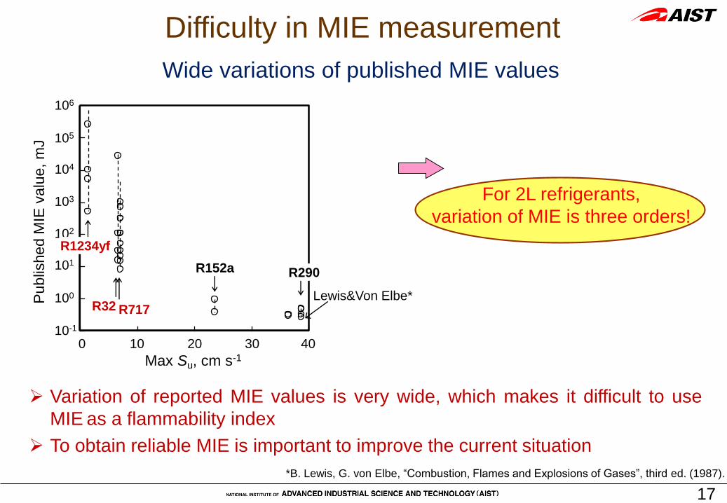
Difficulty in MIE measurement
For 2L refrigerants,
variation of MIE is three orders!
Wide variations of published MIE values
1.E-01
1.E+00
1.E+01
1.E+02
1.E+03
1.E+04
1.E+05
1.E+06
0 10 20 30 40
Su,max, cm/s
MIE
, m
J
Max Su, cm s-1
101
103
104
105
106
102
100
10-1
Publis
hed M
IE v
alu
e, m
J
200 30 4010
R1234yf
R290R152a
R717R32Lewis&Von Elbe*
Variation of reported MIE values is very wide, which makes it difficult to use
MIE as a flammability index
To obtain reliable MIE is important to improve the current situation
*B. Lewis, G. von Elbe, “Combustion, Flames and Explosions of Gases”, third ed. (1987).
18
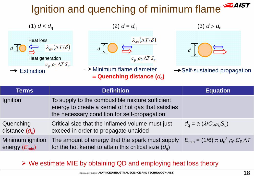
(2) d = dq
d
Minimum flame diameter
Quenching distance (dq)
(1) d < dq
Heat generation
Heat loss
d
Extinction
(3) d dq
d
Self-sustained propagation
Ignition and quenching of minimum flame
We estimate MIE by obtaining QD and employing heat loss theory
Terms Definition Equation
Ignition To supply to the combustible mixture sufficient
energy to create a kernel of hot gas that satisfies
the necessary condition for self-propagation
Quenching
distance (dq)
Critical size that the inflamed volume must just
exceed in order to propagate unaided
dq = a (/CP0Su)
Minimum ignition
energy (Emin)
The amount of energy that the spark must supply
for the hot kernel to attain this critical size (dq)
Emin = (1/6) dq3 0 CPT

19
DC
spark
Micrometer
Electrodes with
parallel plates
-
+
Acrylic cylinder
R290, d =1.7 mm
Quenching distance measurement
・DC spark
Duration of 1-10 ms
Energy of 0.1-5 J
3. Type of ignition spark
R290
R600a
R152a
HFO-1243zf
HFC-143
R152a/134a (50/50 v/v)
HFC-254fb
R717
R143a
R32
R1234yf
1. Compound
・AC spark
Neon transformer
Duration of 100 ms
Energy of 2.5 J
Considering wide use of the test method and values, we tested various conditions:
d
Under microgravity
Vertical position* Horizontal position
2. Configuration of parallel plates
*ASTM E582-07 “Standard Test Method for Minimum Ignition Energy
and Quenching Distance in Gaseous Mixtures” (2007)

20
QD measurement in g
dq
-R1234yf, 10 vol%-
d = 24.9mm
Ignited
d = 24.7mm
Not ignited

21
(uSu0,max)-1 (102 kg-1 m2 s)
R717
R1234yf
R290
dq
,mm
dq,h
dq,v
dq in g
+
Obtained a single continuous function between dq and Su from highly to only
mildly flammable compounds
Su <10 cm s-1 dq 5 mm
Results of QD-Relationship between QD and BV-
0
5
10
15
20
25
0 10 20 30 40
Su0, max, cm s-1
dq,
mm
dq,
mm le
ss fla
mm
able
less flammable
less fla
mm
able
more flammableSu0,max, cm s-1
R717
R32
R1234yf
R290
+ ASTM configuration
g
Parallel plates in the
horizontal direction

22
ubpbq TTCdE 3
min 26/1This study:
δ
dq-2
ASTM configuration
Parallel plates in the
horizontal direction
R3
2R
71
7
R2
90
R1234yf
Estimation of MIE
Su, dq
Reported Emin are at most 3 orders of magnitude different
Our estimation agreed with lower value of reported Emin for all the compounds
without adding any modifications
Emin was essentially proportional to the cube of dq
Comparison between
estimation and experiment
Exp. values in this study
Theoretical eq. of Emin
Minimum flame

23
1. Background
- Importance of evaluating low flammability
2. Fundamental flammability properties
3. MIE and quenching distance
4. Flame extinction diameter
-Index of safe design of electric parts
5. Summary R152a flame goes out through
opening of MC

24
Measurement of flame extinction diameter d*
d
h
PTFE plate of 1
mm in thickness
Acrylic cylinder
R1234yf, g (9.4%, d = 10mm)
“No go”
Opening
R290 (4.5%, d = 1.25mm)
“Go”
Opening

25
Results of flame extinction diameter
R-32/NH3/254fbの比較
0
1
2
3
4
5
6
7
8
0 10 20 30 40 50 60 70
h , mm
d*,
mm
R-32
R-717
HFC-254fb
d* was positively related to dq, negatively related to Su
With increasing h (growing flame sphere), d* decreased and converged
(No go)
(Go)
d* of 2L refs as a function of hQD
Comparison of d* (@h = 9mm)
MC for 65A:
13.23.0 mm
Socket:
7.02.3 mm
R290 flame can pass the opening of socket
R32 flame cannot pass the opening of MC
h, mm
d*
,mm
R32
R717
HFC-254fb

26
R32
R290
Exti
nct
ion
dia
me
ter
(d*)
,mm
2
4
6
8
10
0
d*(R32) > D(MC)
Structureof electric parts
Flammabilitycharacteristics
No go
Go
Compressor
MC
Outdoor unit
Opening of MC
Leakof refrigerant
-R290 flame having a high BV can pass the opening of socket
-2L flame having a low BV cannot pass the opening of MC
Based on our experiment and theory, we can identify potential ignition sources of
flammable refrigerants
Summary of part 4

27
Summary
1. Evaluation of low flammability becomes practically important because
the less flammable a material is, the more widely it will be accepted
We are trying to develop evaluation methods and give the values to help
development of good materials
Sumax vs GWP 100yr
0
10
20
30
40
1 10 100 1000 10000GWP 100yr
Sum
ax
1000 10000
20
30
40
R410AR125
R134a
GWP, -
R32
Fuel
Current refrigerant
R152a
R717
R290
R600a
1) AMOLEA: R1123/32 (45/55)
2) DR-55: R32/125/1234yf (67/7/26)S
u0
,ma
x, cm
s-1
R32
AMOLEA1) DR-552)
GWP, -1 10 100
0R744
Low GWP & Low Flammability
10Su
0,m
ax, cm
s-1

28
(uSu0,max)-1
R717
R1234yf
R290
dq
,mm
dq,h
dq,v
dq in g
+
less fla
mm
able
less flammable
Based on this correlation, we estimated Emin as a starting point
We will further study ignition and extinction characteristics applicable to
practical risk assessment of 2L refrigerants
2. In the NEDO project, we studied ignition and extinction of refrigerants
We measured QD for various compounds by various conditions and
obtained a single correlation between Su and dq
2L
Thank you!