4 flexural members - dres.ir formed steel design... · 4 flexural members 4.1 general remarks ......
TRANSCRIPT

146
4 Flexural Members
4.1 GENERAL REMARKS
Beams are used to support transverse loads and/or applied moment.Cold-formed steel sections, such as I-sections, channels, Z-shapes, angles,T-sections, hat sections, and tubular members (Fig. 1.2) and decks and panels(Fig. 1.11) can be used as flexural members.
In the design of cold-formed steel flexural members, consideration shouldfirst be given to the moment-resisting capacity and the stiffness of the mem-ber. It may be found that in many cases, the moment of inertia of the sectionis not a constant value but varies along the span length due to the noncom-pactness of the thin-walled section and the variation of the moment diagram.The design method is discussed in this chapter. Second, the webs of beamsshould be checked for shear, combined bending and shear, web crippling, andcombined bending and web crippling.
In addition to the design features discussed above, the moment-resistingcapacity of the member may be limited by lateral buckling of the beam,particularly when the section is fabricated from thin material and laterallysupported at relatively large intervals. For this reason, flexural members mustbe braced adequately in accordance with the bracing requirements prescribedin the AISI Specification; otherwise a low design moment has to be used. Forsome sections, distortional buckling may be critical.
Unlike hot-rolled heavy steel sections, in the design of thin-walled cold-formed steel beams, special problems such as shear lag and flange curling arealso considered to be important matters due to the use of thin material. Fur-thermore, the design of flexural members can be even more involved if theincrease of steel mechanical properties due to cold work is to be utilized.
Based on the above general discussion, the following design features areconsidered in this chapter with some design examples for the purpose ofillustration:
1. Bending strength and deflection2. Design of webs for shear, combined bending and shear, web crippling,
and combined bending and web crippling3. Bracing requirements4. Shear lag5. Flange curling

4.2 BENDING STRENGTH AND DEFLECTION 147
In general, long-span, shallow beams are governed by deflection andmedium-length beams are controlled by bending strength. For short-spanbeams, shear strength may be critical.
For design tables and charts, reference should be made to Part II of theAISI Design Manual.
4.2 BENDING STRENGTH AND DEFLECTION
4.2.1 Introduction
In the design of flexural members, sufficient bending strength must be pro-vided, and at the same time the deflection of the member under service loadsshould not exceed specific limitations.
A. ASD Method
According to the design format discussed in Art 3.3.1.1 for the ASD method,Eq. (4.1) gives the following structural safety requirement for the flexural orbending strength:
M � M (4.1)a
where M � required flexural strength or bending moment for ASDcomputed from nominal loads or working loads
Ma � allowable design flexural strength or bending moment de-termined by Eq. (4.2):
MnM � (4.2)a �b
In Eq. (4.2), �b � factor of safety for flexural or bending strength� 1.67 on the basis of Sec. 3.1.1 of the AISI Specification
Mn � smallest nominal flexural strength or moment determinedfrom the following four design considerations:1. Section strength or bending moment of the cross sec-
tion calculated in accordance with Art. 4.2.22. Lateral–torsional buckling strength calculated in ac-
cordance with Art. 4.2.33. Section strength of beams having one flange through-
fastened to deck or sheathing determined in accordancewith Art. 4.2.4
4. Section strength of beams having one flange fastenedto a standing seam roof system determined in accord-ance with Art. 4.2.5

148 FLEXURAL MEMBERS
In addition to the above-listed four cases, consideration should also begiven to shear lag problems for unusually short span beams (see Art. 4.2.6).The current AISI design provisions do not consider torsional effects, such asthose resulting from loads that do not pass through the shear center of thecross section.1.333 For torsional analysis, see Appendix B.
B. LRFD Method
Based on the design format discussed in Art. 3.3.2.1 for the LRFD method,the structural safety requirement for the flexural or bending strength is ex-pressed in Eq. (4.3):
M � � M (4.3)u b n
where Mu � required flexural strength or bending moment for LRFD com-puted from factored loads (see Arts. 3.3.2.1 and 3.3.2.2)
�b � resistance factor for reducing the flexural strength or bendingmoment
� 0.95 for the nominal section strength of flexural members withstiffened or partially stiffened compression flanges (Art. 4.2.2)
� 0.90 for the nominal section strength of flexural members withunstiffened compression flanges (Art. 4.2.2), the nominallateral-torsional buckling strength (Art. 4.2.3), the sectionstrength of beams having one flange through-fastened to deckor sheathing (Art. 4.2.4), and the section strength of beams hav-ing one flange fastened to a standing seam roof system (Art.4.2.5).
�bMn � design flexural strength or bending moment
Mn was defined in Item A for the ASD method.
4.2.2 Section Strength or Bending Moment of the Cross Section
Section C3.1.1 of the 1996 edition of the AISI Specification includes twodesign procedures for calculating the section strength of flexural members.Procedure I is based on ‘‘Initiation of Yielding’’ and Procedure II is based on‘‘Inelastic Reserve Capacity.’’ Both design procedures are discussed in thisArticle.
4.2.2.1 Initiation of Yielding In Procedure I of the AISI Specification, thenominal moment, Mn, of the cross section is the effective yield moment, My,determined on the basis of the effective areas of flanges and the beam web.The effective width of the compression flange and the effective depth of theweb can be computed from the design equations presented in Chapter 3.
Similar to the design of hot-rolled steel shapes, the yield moment My of acold-formed steel beam is defined as the moment at which an outer fiber(tension, compression, or both) first attains the yield point of steel. This is

4.2 BENDING STRENGTH AND DEFLECTION 149
Figure 4.1 Stress distribution for yield moment. (a) Balanced sections. (b) Neutralaxis close to compression flange (initial yielding in tension flange). (c) Neutral axisclose to tension flange (initial yielding in compression flange).
the maximum bending capacity to be used in elastic design. Figure 4.1showsseveral types of stress distribution for yield moment based on different lo-cations of the neutral axis. For balanced sections (Fig. 4.1a) the outer fibersin the compression and tension flanges reach the yield point at the same time.However, if the neutral axis is eccentrically located, as shown in Figs. 4.1band c, the initial yielding takes place in the tension flange for case b and inthe compression flange for case c.
Based on the above discussion, the nominal section strength for initiationof yielding is calculated by using Eq. (4.4):
M � M � S F (4.4)n y e y
150 FLEXURAL MEMBERS
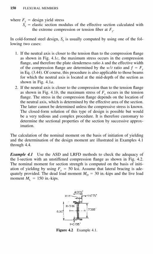
Figure 4.2 Example 4.1.
where Fy � design yield stressSe � elastic section modulus of the effective section calculated with
the extreme compression or tension fiber at Fy.
In cold-formed steel design, Se is usually computed by using one of the fol-lowing two cases:
1. If the neutral axis is closer to the tension than to the compression flangeas shown in Fig. 4.1c, the maximum stress occurs in the compressionflange, and therefore the plate slenderness ratio � and the effective widthof the compression flange are determined by the w / t ratio and ƒ � Fy
in Eq. (3.44). Of course, this procedure is also applicable to those beamsfor which the neutral axis is located at the mid-depth of the section asshown in Fig. 4.1a.
2. If the neutral axis is closer to the compression than to the tension flangeas shown in Fig. 4.1b, the maximum stress of Fy occurs in the tensionflange. The stress in the compression flange depends on the location ofthe neutral axis, which is determined by the effective area of the section.The latter cannot be determined unless the compressive stress is known.The closed-form solution of this type of design is possible but wouldbe a very tedious and complex procedure. It is therefore customary todetermine the sectional properties of the section by successive approx-imation.
The calculation of the nominal moment on the basis of initiation of yieldingand the determination of the design moment are illustrated in Examples 4.1through 4.4.
Example 4.1 Use the ASD and LRFD methods to check the adequacy ofthe I-section with an unstiffened compression flange as shown in Fig. 4.2.The nominal moment for section strength is computed on the basis of initi-ation of yielding by using Fy � 50 ksi. Assume that lateral bracing is ade-quately provided. The dead load moment MD � 30 in.-kips and the live loadmoment ML � 150 in.-kips.
4.2 BENDING STRENGTH AND DEFLECTION 151
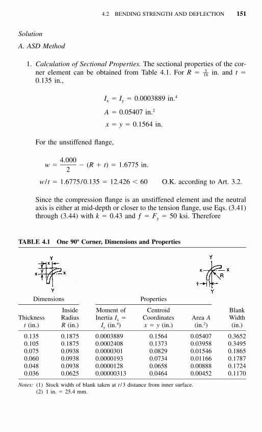
TABLE 4.1 One 90� Corner, Dimensions and Properties
Dimensions
Thicknesst (in.)
InsideRadiusR (in.)
Properties
Moment ofInertia Ix �
Iy (in.4)
CentroidCoordinatesx � y (in.)
Area A(in.2)
BlankWidth(in.)
0.1350.1050.0750.0600.0480.036
0.18750.18750.09380.09380.09380.0625
0.00038890.00024080.00003010.00001930.00001280.00000313
0.15640.13730.08290.07340.06580.0464
0.054070.039580.015460.011660.008880.00452
0.36520.34950.18650.17870.17240.1170
Notes: (1) Stock width of blank taken at t / 3 distance from inner surface.(2) 1 in. � 25.4 mm.
Solution
A. ASD Method
1. Calculation of Sectional Properties. The sectional properties of the cor-ner element can be obtained from Table 4.1. For R � in. and t �3––16
0.135 in.,
4I � I � 0.0003889 in.x y
2A � 0.05407 in.
x � y � 0.1564 in.
For the unstiffened flange,
4.000w � � (R � t) � 1.6775 in.
2
w / t � 1.6775/0.135 � 12.426 � 60 O.K. according to Art. 3.2.
Since the compression flange is an unstiffened element and the neutralaxis is either at mid-depth or closer to the tension flange, use Eqs. (3.41)through (3.44) with k � 0.43 and ƒ � Fy � 50 ksi. Therefore

152 FLEXURAL MEMBERS
1.052 w ƒ� � (3.44)� � �t E�k
1.052 50� (12.426) �29,500�0.43
� 0.821 � 0.673
0.22� � 1 � � (3.43)� ���
0.22� 1 � 0.821� ��0.821
� 0.892
b � �w � 0.892(1.6775)
� 1.4963 in.
By using the effective width of the compression flange and assumingthe web is fully effective, the location of the neutral axis, the momentof inertia Ix and the elastic section modulus of the effective section Se
can be computed as follows.
Element Area A (in.2)
Distance fromTop Fiber y
(in.)Ay
(in.3)Ay 2
(in.4)
Top flange 2(1.4963)(0.135) � 0.4040 0.0675 0.0273 0.0018Top corners 2(0.05407) � 0.1081 0.1564 0.0169 0.0026Webs 2(7.355)(0.135) � 1.9859 4.0000 7.9436 31.7744Bottom corners 2(0.05407) � 0.1081 7.8436 0.8479 6.6506Bottom flange 2(1.6775)(0.135) � 0.4529 7.9325 3.5926 28.4983
Total 3.0590 12.4283 66.9277
� 4.063 in.�(Ay) 12.4283
y � �cg � A 3.0590
Since ycg � d /2 � 4.00 in., initial yield occurs in the compressionflange. Prior to computing the moment of inertia, check the web for fulleffectiveness by using Fig. 4.3 as follows:
ƒ � 50(3.7405/4.063) � 46.03 ksi (compression)1
ƒ � �50(3.6145/4.063) � �44.48 ksi (tension)2
� � ƒ /ƒ � �0.966 (3.58)2 1

4.2 BENDING STRENGTH AND DEFLECTION 153
Figure 4.3 Stress distribution in webs.
3k � 4 � 2(1 � �) � 2(1 � �) (3.57)3� 4 � 2[1 � (�0.966)] � 2[1 � (�0.966)]
� 23.13
h � 7.355 in.
h / t � 7.355/0.135 � 54.48 � 200
O.K. according to Art. 3.2.
1.052 46.03� � (54.48) � 0.471 � 0.673 (3.44)�29,500�23.13
� � 1.0 (3.43)
b � h � 7.355 in.e
b � b / (3 � �) (3.54)1 e
� 7.355/[3 � (�0.966)] � 1.855 in.
Since � � �0.236,
b � b /2 � 3.6775 in.2 e (3.55)
b � b � 1.855 � 3.6775 � 5.5325 in.1 2

154 FLEXURAL MEMBERS
Since (b1 � b2) is greater than the compression portion of the web of3.7405 in., the web is fully effective as assumed. The total Ix is
2(Ay ) � 66.9277�1 3––2I � 2( )(0.135)(7.355) � 8.9522web 12
2 2� A (y ) � (3.0590)(4.063) � �50.4979�� � cg
4I � 25.3820 in.x
The elastic section modulus relative to the top fiber is
I 25.3820x 3S � � � 6.247 in.e y 4.063cg
2. Nominal and Allowable Design Moments. The nominal moment for sec-tion strength is
M � S F � (6.247)(50) � 312.35 in.- kipsn e y
The allowable design moment is
M � M /� � 312.35/1.67 � 187.0 in.-kipsa n b
3. Required Moment. Based on the load combination discussed in Art.3.3.1.2, the required moment for the given dead load moment and liveload moment is computed as follows:
M � M � MD L (3.3b)
� 30 � 150 � 180 in.-kips
Since M � Ma, the I-section is adequate for the ASD method.
B. LRFD Method
1. Nominal and Design Moments. The nominal moment for the LRFDmethod is the same as that used for the ASD method, i.e.,
M � 312.35 in.-kipsn
The design moment for the I-section having an unstiffened compressionflange (�b � 0.90) is
4.2 BENDING STRENGTH AND DEFLECTION 155
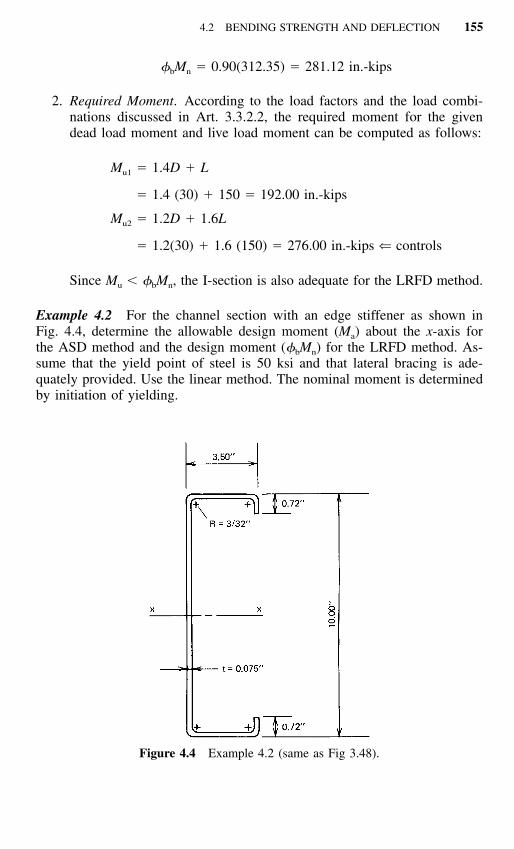
Figure 4.4 Example 4.2 (same as Fig 3.48).
� M � 0.90(312.35) � 281.12 in.-kipsb n
2. Required Moment. According to the load factors and the load combi-nations discussed in Art. 3.3.2.2, the required moment for the givendead load moment and live load moment can be computed as follows:
M � 1.4D � Lu1
� 1.4 (30) � 150 � 192.00 in.-kips
M � 1.2D � 1.6Lu2
� 1.2(30) � 1.6 (150) � 276.00 in.-kips ⇐ controls
Since Mu � �bMn, the I-section is also adequate for the LRFD method.
Example 4.2 For the channel section with an edge stiffener as shown inFig. 4.4, determine the allowable design moment (Ma) about the x-axis forthe ASD method and the design moment (�bMn) for the LRFD method. As-sume that the yield point of steel is 50 ksi and that lateral bracing is ade-quately provided. Use the linear method. The nominal moment is determinedby initiation of yielding.

156 FLEXURAL MEMBERS
Figure 4.5 Line elements.
Solution
A. ASD Method
1. Calculation of Sectional Properties. In order to simplify the calculation,line elements, as shown in Fig. 4.5, are used for the linear method.
i. Corner element (Figs. 1.31 and 4.5)
tR� � R � � 0.131 in.
2
Arc length
L � 1.57R� � 0.206 in.
c � 0.637R� � 0.0836 in.
ii. Effective width of the compression flange. For the given channelsection with equal flanges, the neutral axis is located either at themid-depth or closer to the tension flange. Therefore, use ƒ � Fy �

4.2 BENDING STRENGTH AND DEFLECTION 157
50 ksi to compute the effective width of the compression flange.For the compression flange,
w � 3.50 � 2(R � t) � 3.1624 in.
w / t � 3.1624/0.075 � 42.17
According to Eq. (3.75)
S � 1.28�E /ƒ � 1.28�29,500/50 � 31.09
Since w / t � S, use Case III of Art. 3.5.3.2 and Eq. (3.90) to computethe required moment of inertia of the edge stiffener Ia as follows:
4I � {[115(w / t) /S] � 5}ta
4 �3 4� {[115(42.17)/31.09] � 5}(0.075) � 5.093 � 10 in.
For the simple lip edge stiffener used for the given channel section,
D � 0.720 in.
d � D � (R � t) � 0.5512 in.
d / t � 0.5512/0.075 � 7.35 � 14 (maximum d / t)
By using Eq. (3.91), the moment of inertia of the full edge stiffeneris
3 �3 4I � d t /12 � 1.047 � 10 in.s
C � I /I � 0.206 � 1.02 s a
D /w � 0.72/3.1624 � 0.228
Since D /w � 0.8 and � � 900, according to Eq. (3.86),
ka � 5.25 � 5(D /w) � 4.11 � 4.0
Use ka � 4.0According to Eq. (3.85),

158 FLEXURAL MEMBERS
nk � C (k � k ) � k2 a u u
1 / 3� (C ) (4.0 � 0.43) � 0.432
1 / 3� (0.206) (3.57) � 0.43
� 2.54 � 4.0
Use k � 2.54 to calculate the plate slenderness factor for the com-pression flange as follows:
� � (1.052/�k)(w / t)�ƒ/E
� (1.052/�2.54)(42.17)�50/29,500 � 1.146 � 0.673
The effective width of the compression flange is
b � �w � [(1 � 0.22/�) /�]w
� [(1 � 0.22/1.146)/1.146](3.1624) � 2.230 in.
iii. Effective width of the edge stiffener. The reduced effective width ofthe edge stiffener with stress gradient can be computed in accord-ance with Art. 3.5.3.2 or Section B3.2 of the AISI Specification.Using k � 0.43, d / t � 7.35 and a conservative ƒ � Fy, the slen-derness factor is
� � (1.052/�0.43)(7.35)�50/29,500 � 0.485 � 0.673
Therefore, the effective width of the edge stiffener is
d � � d � 0.5512 in.s
Based on Eq. (3.87), the reduced effective width of the edge stiff-ener is
d � C d � � 0.206(0.5512) � 0.113 in.s 2 s
The above calculation indicates that the compression stiffener isnot fully effective.
iv. Location of neutral axis and computation of Ix and Sx
a. Location of neutral axis based on full web element. Assumingthat the web element (Element 7 in Fig. 4.6) is fully effective,the neutral axis can be located by using the following table. SeeFig. 4.6 for dimensions of elements.

4.2 BENDING STRENGTH AND DEFLECTION 159
Figure 4.6 Effective lengths and stress distribution using fully effective web.
ElementEffective Length L
(in.)
Distance fromTop Fiber y
(in.)Ly
(in.2)
1 0.5512 9.5556 5.26702 2(0.206) � 0.4120 9.9148 4.08493 3.1624 9.9625 31.50544 2(0.206) � 0.4120 0.0852 0.03515 2.2300 0.0375 0.08366 0.1130 0.2254 0.02557 9.6624 5.0000 48.3120
Total 16.5430 89.3135
� 5.399 in.�(Ly) 89.3135
y � �cg � L 16.5430
Use Art. 3.5.1.2 or Section B2.3 of the AISI Specification tocheck the effectiveness of the web element. From Fig. 4.6,
ƒ � 50(5.2302/5.399) � 48.44 ksi (compression)1
ƒ � �50(4.4322/5.399) � �41.05 ksi (tension)2

160 FLEXURAL MEMBERS
� � ƒ /ƒ � �0.8472 1
3k � 4 � 2(1 � �) � 2(1 � �) � 20.30
h / t � 9.6624/0.075 � 128.83 � 200 O.K.
1.052 48.44� � (128.83) � 1.219 � 0.673�29,500�20.30
� � [1 � 0.22/�] /� � 0.672
b � �h � 0.672 � 9.6624 � 6.4931 in.e
b � b / (3 � �) � 1.6878 in.1 e
Since � � �0.236,
b � b /2 � 3.2465 in.2 e
b � b � 4.9343 in.1 2
Since the value of (b1 � b2) is less than 5.2302 in. shown inFig. 4.6, the web element is not fully effective as assumed. Theneutral axis should be relocated by using the partially effectiveweb. The procedure is interative as illustrated below.
b. Location of neutral axis based on ineffective web elements. Asthe first iteration, the ineffective portion of the web can be as-sumed as follows:
5.2302 � (b � b ) � 5.2302 � 4.9343 � 0.2959 in.1 2
Therefore, the effective lengths of all elements are shown in Fig.4.7 using partially effective web.
ElementEffective Length L
(in.)
Distance fromTop Fiber y
(in.)Ly
(in.2)
1 0.5512 9.5556 5.26702 0.4120 9.9148 4.08493 3.1624 9.9625 31.50544 0.4120 0.0852 0.03515 2.2300 0.0375 0.08366 0.1130 0.2254 0.02557 7.6787 5.9919 46.01008 1.6878 1.0127 1.7092
16.2471 88.7207
88.7207y � � 5.461 in.cg 16.2471

4.2 BENDING STRENGTH AND DEFLECTION 161
Figure 4.7 Effective lengths and stress distribution using partially effective web (firstiteration).
From Fig. 4.7,
ƒ � 48.45 ksi (compression)1
ƒ � �40.01 ksi (tension)2
� � �0.826
k � 19.83
h / t � 128.83
1.052 48.45� � (128.83) � 1.233 � 0.673�29,500�19.83
� � [1 � 0.22/1.233]/1.233 � 0.666
b � �h � 6.4352 in.e
b � b / (3 � �) � 1.6820 in.1 e
b � b /2 � 3.2176 in.2 e
b � b � 4.8996 in.1 2

162 FLEXURAL MEMBERS
Because the above computed value of (b1 � b2) is less than theprevious value of 4.9343 in. by 0.7%, additional iterations arerequired.
For the second iteration, the ineffective portion of the webis
5.2922 � (b � b ) � 5.2922 � 4.8966 � 0.3926 in.1 2
By using the same procedure shown above, the neutral axis canbe relocated as follows:
ElementEffective Length
L (in.)
Distance fromTop Fiber y
(in.)Ly
(in.2)Ly 2
(in.3)
1 0.5512 9.5556 5.2670 50.32982 0.4120 9.9148 4.0849 40.50093 3.1624 9.9625 31.5054 313.87274 0.4120 0.0852 0.0351 0.00305 2.2300 0.0375 0.0836 0.00316 0.1130 0.2254 0.0255 0.00577 7.5878 6.0373 45.8098 276.56758 1.6820 1.0098 1.6985 1.7151
16.1504 88.5098 682.9977
88.5098y � � 5.481 in.cg 16.1504
From Fig. 4.8,
ƒ � 48.46 ksi (compression)1
ƒ � �39.68 ksi (tension)2
� � �0.819
k � 19.68
h / t � 128.83
1.052 48.46� � (128.83) � 1.238 � 0.673�29,500�19.68
� � [1 � 0.22/1.238]/1.238 � 0.664
b � �h � 6.4158 in.e
b � b / (3 � �) � 1.6800 in.1 e
4.2 BENDING STRENGTH AND DEFLECTION 163
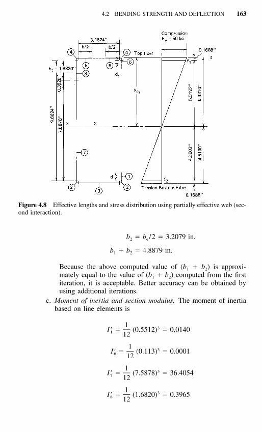
Figure 4.8 Effective lengths and stress distribution using partially effective web (sec-ond interaction).
b � b /2 � 3.2079 in.2 e
b � b � 4.8879 in.1 2
Because the above computed value of (b1 � b2) is approxi-mately equal to the value of (b1 � b2) computed from the firstiteration, it is acceptable. Better accuracy can be obtained byusing additional iterations.
c. Moment of inertia and section modulus. The moment of inertiabased on line elements is
1 3I� � (0.5512) � 0.01401 12
1 3I� � (0.113) � 0.00016 12
1 3I� � (7.5878) � 36.40547 12
1 3I� � (1.6820) � 0.39658 12

164 FLEXURAL MEMBERS
2(Ly ) � 682.9977�3I� � 719.8137 in.z
2 2� L (y ) � �(16.1504)(5.481) � �485.1800�� � cg
3I� � 234.6337 in.x
4I � I� t � (234.6337)(0.075) � 17.598 in.x x
17.598 3S � � 3.211 in.x 5.481
2. Nominal and Allowable Design Moments. The nominal mo-ment for section strength is
M � S F � S F � 3.211(50) � 160.55 in.-kipsn e y x y
The allowable design moment is
M � M /� � 160.55/1.67 � 96.14 in.-kipsa n b
B. LRFD Method
The nominal moment for the LRFD method is the same as that computed forthe ASD method. From Item A above, the nominal moment about the x-axisof the channel section is
M � 160.55 in.-kipsn
Based on Art. 4.2.1 or Sec. C3.1.1 of the AISI Specification, the designmoment for the channel section having a partially stiffened compressionflange (�b � 0.95) is
� M � 0.95(160.55) � 152.52 in.-kipsb n
Example 4.3 For the hat section with a stiffened compression flange asshown in Fig. 4.9, determine the allowable design moment (Ma) about thex-axis for the ASD method and the design moment (�bMn) for the LRFDmethod. Assume that the yield point of steel is 50 ksi. Use the linear method.The nominal moment is determined by initiation of yielding.

4.2 BENDING STRENGTH AND DEFLECTION 165
Figure 4.9 Example 4.3.
Solution
A. ASD Method
1. Calculation of Sectional Properties. In order to use the linear method,midline dimensions are shown in Fig. 4.10.A. Corner element (Figs. 1.31 and 4.10)
R� � R � t /2 � 0.240 in.
Arc length
L � 1.57R� � 0.3768 in.
c � 0.637R� � 0.1529 in.
B. Location of neutral axisa. First approximation. For the compression flange,
w � 15 � 2(R � t) � 14.415 in.
w� 137.29
t

166 FLEXURAL MEMBERS
Figure 4.10 Line elements.
Using Eqs. (3.41) through (3.44) and assuming ƒ � Fy � 50 ksi.
1.052 50� � (137.29) � 2.973 � 0.673�29,500�4
0.22� � 1 � 2.973 � 0.311� ��2.973
b � �w � 0.311(14.415) � 4.483 in.
By using the effective width of the compression flange andassuming that the web is fully effective, the neutral axis can belocated as follows:
ElementEffective Length L
(in.)
Distancefrom TopFiber y
(in.) Ly (in.2)
1 2 � 1.0475 � 2.0950 9.9475 20.84002 2 � 0.3768 � 0.7536 9.8604 7.43083 2 � 9.4150 � 18.8300 5.0000 94.15004 2 � 0.3768 � 0.7536 0.1396 0.10525 4.4830 0.0525 0.2354
Total 26.9152 122.7614
� (Ly) 122.7614y � � � 4.561 in.cg � L 26.9152
4.2 BENDING STRENGTH AND DEFLECTION 167
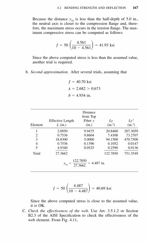
Because the distance ycg is less than the half-depth of 5.0 in.,the neutral axis is closer to the compression flange and, there-fore, the maximum stress occurs in the tension flange. The max-imum compressive stress can be computed as follows:
4.561ƒ � 50 � 41.93 ksi� �10 � 4.561
Since the above computed stress is less than the assumed value,another trial is required.
b. Second approximation. After several trials, assuming that
ƒ � 40.70 ksi
� � 2.682 � 0.673
b � 4.934 in.
ElementEffective Length
L (in.)
Distancefrom TopFiber y
(in.)Ly
(in.2)Ly 2
(in.3)
1 2.0950 9.9475 20.8400 207.30592 0.7536 9.8604 7.4308 73.27073 18.8300 5.0000 94.1500 470.75004 0.7536 0.1396 0.1052 0.01475 4.9340 0.0525 0.2590 0.0136
Total 27.3662 122.7850 751.3549
122.7850y � � 4.487 in.cg 27.3662
4.487ƒ � 50 � 40.69 ksi� �10 � 4.487
Since the above computed stress is close to the assumed value,it is OK.
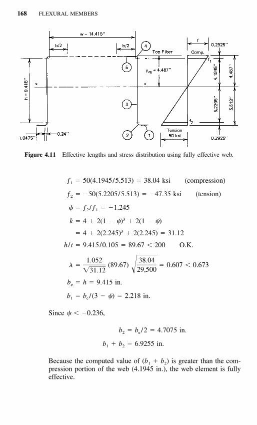
C. Check the effectiveness of the web. Use Art. 3.5.1.2 or SectionB2.3 of the AISI Specification to check the effectiveness of theweb element. From Fig. 4.11,
168 FLEXURAL MEMBERS
Figure 4.11 Effective lengths and stress distribution using fully effective web.
ƒ � 50(4.1945/5.513) � 38.04 ksi (compression)1
ƒ � �50(5.2205/5.513) � �47.35 ksi (tension)2
� � ƒ /ƒ � �1.2452 1
3k � 4 � 2(1 � �) � 2(1 � �)3� 4 � 2(2.245) � 2(2.245) � 31.12
h / t � 9.415/0.105 � 89.67 � 200 O.K.
1.052 38.04� � (89.67) � 0.607 � 0.673�29,500�31.12
b � h � 9.415 in.e
b � b / (3 � �) � 2.218 in.1 e
Since � � �0.236,
b � b /2 � 4.7075 in.2 e
b � b � 6.9255 in.1 2
Because the computed value of (b1 � b2) is greater than the com-pression portion of the web (4.1945 in.), the web element is fullyeffective.

4.2 BENDING STRENGTH AND DEFLECTION 169
D. Moment of inertia and section modulus. The moment of inertiabased on line elements is
1 32I� � 2 (9.415) � 139.0944� �3 122(Ly ) � 751.3549�
3I� � 890.4493 in.z
2 2 3�(�L)(y ) � �27.3662(4.487) � �550.9683 in.cg
3I� � 339.4810 in.x
The actual moment of inertia is
4I � I� t � (339.4810)(0.105) � 35.646 in.x x
The section modulus relative to the extreme tension fiber is
3S � 35.646/5.513 � 6.466 in.x
2. Nominal and Allowable Design Moments. The nominal moment forsection strength is
M � S F � S F � (6.466)(50) � 323.30 in.-kipsn e y x y
The allowable design moment is
M � M /� � 323.30/1.67 � 193.59 in.-kipsa n b
B. LRFD Method
The nominal moment for the LRFD method is the same as that computed forthe ASD method. From Item A above, the nominal moment about the x-axisof the hat section is
M � 323.30 in.-kipsn
Based on Art. 4.2.1 or Sec. C3.1.1 of the AISI Specification, the designmoment for the hat section having a stiffened compression flange (�b � 0.95)is
� M � 0.95 (323.30) � 307.14 in.-kipsb n

170 FLEXURAL MEMBERS
Figure 4.12 Example 4.4.
Example 4.4 For the section with an intermediate stiffener as shown in Fig.4.12, determine the allowable design moment (Ma) about the x-axis for theASD method and the design moment (�bMn) for the LRFD method. Use thelinear method with Fy � 33 ksi. The nominal moment is determined byinitiation of yielding.
Solution
A. ASD Method
1. Calculation of Sectional Properties. Using the linear method as shownin Fig. 4.13.A. Corner element (Figs. 1.31 and 4.13).
tR� � R � � 0.1313 in.
2
Arc length
L � 1.57R� � 1.57(0.1313) � 0.2063 in.
c � 0.637R� � 0.637(0.1313) � 0.0836 in.
B. Location of neutral axisa. First approximation. For the top compression flange,
b � 12 � 2(R � t) � 11.6624 in.o
b / t � 11.6624/0.075 � 155.50 in.o
Assuming that ƒ � Fy and using Eq. (3.75),

4.2 BENDING STRENGTH AND DEFLECTION 171
Figure 4.13 Example 4.4; line elements.
S � 1.28�E /ƒ � 1.28�29,500/33 � 38.27
Since bo / t � (3S � 114.81), use Eq. (3.72) of Art. 3.5.3.1 tocompute the required moment of inertia of the intermediate stiff-ener as follows:
4I � {[128(b / t) /S] � 285}ta o
4� {[128(155.50)/38.27] � 285}(0.075) � 7.439�3 4� 10 in.
The actual moment of inertia of the full intermediate stiffener(Elements 7, 8, and 9 in Fig. 4.13) about its own centroidal axisparallel to the top compression flange is computed below.
1 3 2I� � 2 (0.7) � 4(0.2063)(0.35 � 0.0836)� �s 123� 0.2123 in.
�3 4I � I�t � 0.2123(0.075) � 15.923 � 10 in.s s
According to Eq. (3.73),
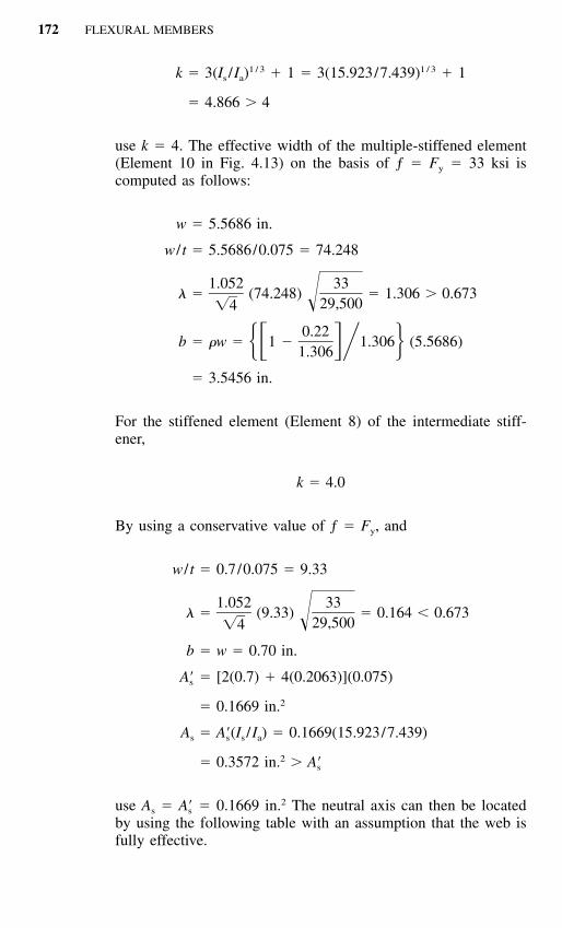
172 FLEXURAL MEMBERS
1 / 3 1 / 3k � 3(I /I ) � 1 � 3(15.923/7.439) � 1s a
� 4.866 � 4
use k � 4. The effective width of the multiple-stiffened element(Element 10 in Fig. 4.13) on the basis of ƒ � Fy � 33 ksi iscomputed as follows:
w � 5.5686 in.
w / t � 5.5686/0.075 � 74.248
1.052 33� � (74.248) � 1.306 � 0.673�29,500�4
0.22b � �w � 1 � 1.306 (5.5686)� � �1.306
� 3.5456 in.
For the stiffened element (Element 8) of the intermediate stiff-ener,
k � 4.0
By using a conservative value of ƒ � Fy, and
w / t � 0.7/0.075 � 9.33
1.052 33� � (9.33) � 0.164 � 0.673�29,500�4
b � w � 0.70 in.
A� � [2(0.7) � 4(0.2063)](0.075)s
2� 0.1669 in.
A � A�(I /I ) � 0.1669(15.923/7.439)s s s a
2� 0.3572 in. � A�s
use As � A � 0.1669 in.2 The neutral axis can then be located�sby using the following table with an assumption that the web isfully effective.

4.2 BENDING STRENGTH AND DEFLECTION 173
ElementEffective Length L
(in.)
Distance fromTop Fiber y
(in.)Ly
(in.2)
1 2 � 0.5812 � 1.1624 4.5406 5.27802 2 � 0.2063 � 0.4126 4.9148 2.02783 2 � 3.1624 � 6.3248 4.9625 31.38684 2 � 0.2063 � 0.4126 4.9148 2.02785 2 � 4.6624 � 9.3248 2.5000 23.31206 2 � 0.2063 � 0.4126 0.0852 0.03527 2 � 0.2063 � 0.4126 0.0852 0.03528 2 � 0.7000 � 1.4000 0.5188 0.72639 2 � 0.2063 � 0.4126 0.9524 0.3930
10 2 � 3.5456 � 7.0912 0.0375 0.2659
Total 27.3662 65.4880
� (Ly) 65.4880y � � � 2.393 in. � 2.50 in.cg � L 27.3662
2.393ƒ � (33) � 30.29 ksi� �5 � 2.393
Since the computed value is considerably less than 33 ksi,additional trials are required. After several trials, it was foundthat the stress should be about 29.68 ksi.
b. Additional approximation. Assuming
ƒ � 29.68 ksi
� � 1.239 � 0.673
b � 3.6964 in.
ElementEffective Length L
(in.)
Distance fromTop Fiber y
(in.)Ly
(in.2)Ly 2
(in.3)
12345678
1.16240.41266.32480.41269.32480.41260.41261.4000
4.54064.91484.96254.91482.50000.08520.08520.5188
5.27802.0278
31.38682.0278
23.31200.03520.03520.7263
23.96539.9664
155.75709.9664
58.28000.00300.00300.3768

174 FLEXURAL MEMBERS
ElementEffective Length L
(in.)
Distance fromTop Fiber y
(in.)Ly
(in.2)Ly 2
(in.3)
910
Total
0.41262 � 3.6964 � 7.3928
27.6678
0.95240.0375
0.39300.2772
65.4993
0.37430.0104
258.7026
65.4993y � � 2.367 in.cg 27.6678
2.367ƒ � (33) � 29.67 ksi� �5 � 2.367
Since the computed stress is close to the assumed value of 29.68ksi, it is O.K.
To check if the web is fully effective, refer to Fig. 4.13:
2.1982ƒ � 33 � 27.55 ksi (compression)� �1 2.633
2.4642ƒ � �33 � �30.88 ksi (tension)� �2 2.633
� � ƒ /ƒ � �1.1212 1
3k � 4 � 2(1 � �) � 2(1 � �) � 27.33
h / t � 4.6624/0.075 � 62.17 � 200 O.K.
1.052 27.55� � (62.17) � 0.382 � 0.673�29,500�27.33
b � h � 4.6624 in.e
b � b / (3 � �) � 4.6624/4.121 � 1.131 in.1 e
Since � � �0.236,
b � b /2 � 2.3312 in.2 e
b � b � 3.4622 � 2.1982 in.1 2
The web is fully effective as assumed.
4.2 BENDING STRENGTH AND DEFLECTION 175
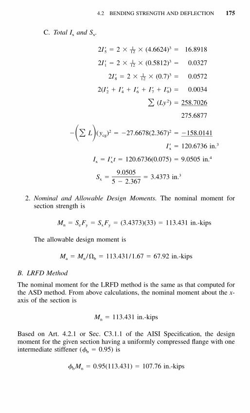
C. Total Ix and Sx.
1 3––2I� � 2 � � (4.6624) � 16.89185 12
1 3––2I� � 2 � � (0.5812) � 0.03271 12
1 3––2I� � 2 � � (0.7) � 0.05728 12
2(I� � I� � I� � I� � I�) � 0.00342 4 6 7 9
2(Ly ) � 258.7026�275.6877
2 2� L (y ) � �27.6678(2.367) � �158.0141�� � cg
3I� � 120.6736 in.x
4I � I� t � 120.6736(0.075) � 9.0505 in.x x
9.0505 3S � � 3.4373 in.x 5 � 2.367
2. Nominal and Allowable Design Moments. The nominal moment forsection strength is
M � S F � S F � (3.4373)(33) � 113.431 in.-kipsn e y x y
The allowable design moment is
M � M /� � 113.431/1.67 � 67.92 in.-kipsa n b
B. LRFD Method
The nominal moment for the LRFD method is the same as that computed forthe ASD method. From above calculations, the nominal moment about the x-axis of the section is
M � 113.431 in.-kipsn
Based on Art. 4.2.1 or Sec. C3.1.1 of the AISI Specification, the designmoment for the given section having a uniformly compressed flange with oneintermediate stiffener (�b � 0.95) is
� M � 0.95(113.431) � 107.76 in.-kipsb n

176 FLEXURAL MEMBERS
4.2.2.2 Effects of Cold Work on Bending Strength The bending strengthof cold-formed steel sections discussed above was based on the mechanicalproperties of the virgin material. The effects of cold work were completelyneglected.
When the effects of cold work are utilized in the determination of bendingstrength, the computation can be performed by one of the following twodesign approaches.
1. Consider the increase in yield point at corners due to cold work andneglect the effects of cold work in all flat portions of the section. Asdiscussed in Chap. 2, the increase in yield point can be found either bythe use of Eq. (2.9) or by tests.
2. Consider the effects of cold work for corners and all flat elements.Equation (2.12) can be used to compute the average yield point of theentire section.
In any design approach, the following procedures may be used:2.17
1. Subdivide the section into a number of elements. Assume a position ofthe neutral axis and the strain in the top fiber. Compute the strains invarious elements based on the assumed neutral axis and the top fiberstrain.
2. Determine the stresses from the stress–strain relationship of the materialin various elements for the computed strains.
3. Locate the neutral axis by iteration until
��A � 0�is satisfied. Then the bending moment can be approximated by
M � �y�A�where � � stress
�A � area for elementy � distance between center of gravity of each element and neu-
tral axis
Results of a study by Winter and Uribe indicate that for the steels com-monly used in thin-walled cold-formed steel construction, considering theeffects of cold work only in the corners of the formed sections, the momentcapacities can be increased by 4 to 22% compared with those obtained whenneglecting cold work.2.17

4.2 BENDING STRENGTH AND DEFLECTION 177
Figure 4.14 Comparison of ultimate moments computed for three different condi-tions.2.17
If the effects of cold work are considered in both the flats and the corners,the increase in bending strength ranges from 17 to 41% above the virginvalue.
It can be seen that a substantial advantage can be obtained by using theincrease in strength of the material. Figure 4.14, reproduced from Ref. 2.17,shows a comparison of the ultimate moments computed for three differentconditions. It should be noted that the effects of cold work as shown in Fig.4.14 may not be directly applied to other configurations because the relativeinfluence of corners or flats on the increase in bending strength dependsmainly on the configuration of the section, and the spread between the tensilestrength and yield point of the virgin material. Attention should be given tothe limitations of Sec. A7.2 of the AISI Specification when the effects of coldwork are used in design.
4.2.2.3 Inelastic Reserve Capacity of Beams Prior to 1980, the inelasticreserve capacity of beams was not included in the AISI Specification becausemost cold-formed steel shapes have width-to-thickness ratios considerably inexcess of the limits required by plastic design. Because of the use of largewidth-to-thickness ratios for beam flange and web, such members are usuallyincapable of developing plastic hinges without local buckling.

178 FLEXURAL MEMBERS
In the 1970s research work on the inelastic strength of cold-formed steelbeams was carried out by Reck, Pekoz, Winter, and Yener at Cornell Uni-versity.4.1–4.4 These studies showed that the inelastic reserve strength of cold-formed steel beams due to partial plastification of the cross section and themoment redistribution of statically indeterminate beams can be significant forcertain practical shapes. With proper care, this reserve strength can be utilizedto achieve more economical design of such members. In Europe, a study hasbeen made by von Unger on the load-carrying capacity of transversely loadedcontinuous beams with thin-walled section, in particular of roof and floordecks with trapezoidal profiles.4.5 In addition, the buckling strength and load-carrying capacity of continuous beams and steel decks have also been studiedby some other investigators.4.6–4.9
In order to utilize the available inelastic reserve strength of certain cold-formed steel beams, new design provisions based on the partial plastificationof the cross section were added in the 1980 edition of the AISI Specification.The same provisions are retained in the 1986 and the 1996 editions of thespecification. According to Procedure II of Sec. C3.1.1 of the specification,the nominal section strengths, Mn, of those beams satisfying certain specificlimitations can be determined on the basis of the inelastic reserve capacitywith a limit of 1.25My or 1.25SeFy. In the above expression, My is the effectiveyield moment determined according to Art. 4.2.2.1. The ratio of Mn /My rep-resents the inelastic reserve strength of a beam cross section.
The nominal moment Mn is the maximum bending capacity of the beamby considering the inelastic reserve strength through partial plastification ofthe cross section. The inelastic stress distribution in the cross section dependson the maximum strain in the compression flange, cu. Based on the Cornellresearch work on hat sections having stiffened compression flanges,4.1 theAISI design provision included in Sec. C3.1.1 of the specification limits themaximum compression strain to be Cyy, that is,
� C (4.5)cu y y
where y � yield strain, � Fy /E, in. / in.E � modulus of elasticity of steel, � 29.5 � 103 ksi (203 GPa)
Fy � yield point of steel, ksiCy � a factor determined as follows:
1. Stiffened compression elements without intermediate stiffenersa. When w / t �1
C � 3.0 (4.6)y
b. When �1 � w / t � �2
w / t � �1C � 3 � 2 (4.7)� �y � � �2 1

4.2 BENDING STRENGTH AND DEFLECTION 179
Figure 4.15 Factor Cy for stiffened compression elements without intermediate stiff-eners.
c. When w / t � �2
C � 1.0 (4.8)y
where
1.11� �1 �F /Ey
1.28� �2 �F /Ey
The relationship between Cy and the w / t ratio of the compressionflange is shown in Fig. 4.15.
2. Unstiffened compression elements
C � 1.0 (4.9)y
3. Multiple-stiffened compression elements and compression elementswith edge stiffeners
C � 1.0 (4.10)y
No limit is placed on the maximum tensile strain in the AISI Specification.

180 FLEXURAL MEMBERS
Figure 4.16 Stress distribution in sections with yielded tension flange at nominalmoment.4.1
On the basis of the maximum compression strain cu allowed in Eq. (4.5),the neutral axis can be located by using Eq. (4.11), and the nominal momentMn can be determined by using Eq. (4.12) as follows:
� � dA � 0 (4.11)
� �y dA � M (4.12)n
where � is the stress in the cross section.For hat sections Reck, Pekoz, and Winter gave the following equations for
the nominal moments of sections with yielded tension flange and sectionswith tension flange not yielded.
a. Sections with Yielded Tension Flange at Nominal Moment.4.1 For the stressdistributions shown in Fig. 4.16, Eqs. (4.13) to (4.18) are used for computingthe values of yc, yt, yp, ycp, ytp, and Mn. For the purpose of simplicity, midlinedimensions are used in the calculation.

4.2 BENDING STRENGTH AND DEFLECTION 181
Figure 4.17 Stress distribution in sections with tension flange not yielded at nominalmoment.4.1
b � b � 2dt cy � (4.13)c 4
y � d � y (4.14)t c
ycy � (4.15)p /cu y
y � y � y (4.16)cp c p
y � y � y (4.17)tp t p
y 4cp 2M � F t b y � 2y y � � (y ) � �n y c c cp p p2 3
ytp� 2y y � � b y (4.18)� � tp p y t2
b. Sections with Tension Flange Not Yielded at Nominal Moment.4.1 For thestress distribution shown in Fig. 4.17, yc is computed from the followingquadratic equation:
12 2y 2 � � C � y (b � 2C d � C b ) � (C d � C b d) � 0 (4.19)� �c y c c y y t y y tCy
Subsequently, the values of yt, yp, and ycp can be computed from Eqs. (4.14),(4.15), and (4.16), respectively.
If yp � yt, then case 4.2.2.3b applies and the nominal moment Mn is com-puted as follows:
182 FLEXURAL MEMBERS
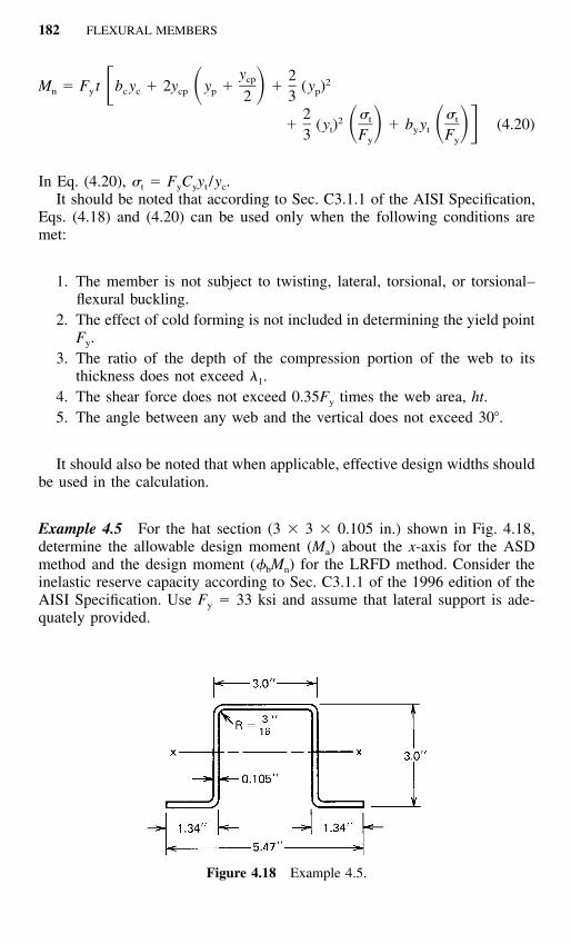
Figure 4.18 Example 4.5.
y 2cp 2M � F t b y � 2y y � � (y ) � �n y c c cp p p2 32 � �t t2� (y ) � b y (4.20)� � � �t y t3 F Fy y
In Eq. (4.20), �t � FyCyyt /yc.It should be noted that according to Sec. C3.1.1 of the AISI Specification,
Eqs. (4.18) and (4.20) can be used only when the following conditions aremet:
1. The member is not subject to twisting, lateral, torsional, or torsional–flexural buckling.
2. The effect of cold forming is not included in determining the yield pointFy.
3. The ratio of the depth of the compression portion of the web to itsthickness does not exceed �1.
4. The shear force does not exceed 0.35Fy times the web area, ht.5. The angle between any web and the vertical does not exceed 30�.
It should also be noted that when applicable, effective design widths shouldbe used in the calculation.
Example 4.5 For the hat section (3 � 3 � 0.105 in.) shown in Fig. 4.18,determine the allowable design moment (Ma) about the x-axis for the ASDmethod and the design moment (�bMn) for the LRFD method. Consider theinelastic reserve capacity according to Sec. C3.1.1 of the 1996 edition of theAISI Specification. Use Fy � 33 ksi and assume that lateral support is ade-quately provided.

4.2 BENDING STRENGTH AND DEFLECTION 183
Figure 4.19 Stress distribution. (a) Midline dimensions. (b) Strain. (c) Stress.
Solution
A. ASD Method
1. Dimensions of Section. By using the midline dimensions and squarecorners, the widths of compression and tension flanges and the depthof webs are computed as follows.
Width of compression flange,
b � 3 � 0.105 � 2.895 in.c
Width of tension flange,
b � 2(1.34 � 0.105/2) � 2.576 in.t
Depth of webs,
d � 3 � 0.105 � 2.895 in.
All dimensions are shown in Fig. 4.19a. Check the effective width ofthe compression flange
w � 3 � 2(3/16 � 0.105) � 2.415 in.
w / t � 2.415/0.105 � 23
k � 4.0
ƒ � F � 33 ksiy
� � (1.052/�4)(23)(�33/29,500) � 0.405 � 0.673
b � w � 2.415 in.
Therefore, the compression flange is fully effective.

184 FLEXURAL MEMBERS
2. Strain Diagram. The w / t ratio of the stiffened compression flange is
w� 23
t
� � 1.11/�F /E1 y
� 1.11/�33/29,500 � 33.2
Since w / t � (�1 � 33.2), according to Eq. (4.6), Cy � 3.0. Thereforecu � 3y, as shown in Fig. 4.19b.
3. Stress Diagram. The values of yc, yt, yp, ycp, and ytp are computed byusing Eqs. (4.13) to (4.17) as follows:
b � b � 2d 2.576 � 2.895 � 2 � 2.895t cy � � � 1.368 in.c 4 4
y � d � y � 2.895 � 1.368 � 1.527 in.t c
y 1.368cy � � � 0.456 in.p / 3cu y
y � y � y � 1.368 � 0.456 � 0.912 in.cp c p
y � y � y � 1.527 � 0.456 � 1.071 in.tp t p
All dimensions are shown in Fig. 4.19c.4. Nominal Moment Mn. In order to utilize the inelastic reserve capacity,
the AISI requirements must be checked.
y 1.368c � � 13.03 � (� � 33.2) (O.K.)1t 0.105
Therefore, the nominal moment is
4 2–M � F t[b y � 2y (y � y /2) � (y )n y c c cp p cp 3 p
� 2y (y � y /2) � b y ]tp p tp t t
� 33(0.105)[(2.895 � 1.368) � 2(0.912)(0.456 � 0.912/2)4 2–� (0.456) � 2(1.071)(0.456 � 1.071/2) � (2 � 1.288)(1.527)]3
� 41.43 in.-kips
5. Yield Moment My. Based on the method illustrated in Example 4.3, Se
for the given hat section is 0.992 in.3 Therefore
4.2 BENDING STRENGTH AND DEFLECTION 185
M � S F � 0.992(33) � 32.74 in.-kipsy e y
1.25M � 1.25(32.74) � 40.93 in.-kipsy
6. Allowable Design Moment Ma. Because Mn exceeds 1.25My, use
M � 1.25M � 40.93 in.-kipsn y
M � M /� � 40.93/1.67 � 24.51 in.-kipsa n b
B. LRFD Method
The nominal moment for the LRFD method is the same as that computed forthe ASD method. From Item A above, the nominal moment about the x-axisof the hat section is
M � 40.93 in.-kipsn
Based on Art. 4.2.1 or Sec. C3.1.1 of the AISI Specification, the designmoment for the hat section having a stiffened compression flange (�b � 0.95)is
� M � 0.95(40.93) � 38.88 in.-kipsb n
Example 4.6 For the I-section with unequal flanges as shown in Fig. 4.20,determine the allowable design moment (Ma) about the x-axis for the ASDmethod and the design moment (�bMn) for the LRFD method. Consider theinelastic reserve capacity and use Fy � 50 ksi. Assume that lateral support isadequately provided to prevent lateral buckling.
Solution
A. ASD Method
1. Dimensions of Section. By using the midline dimensions and squarecorners, the widths of compression and tension flanges and the depthof webs are computed as follows: The flat width of the unstiffenedcompression flange according to Art. 3.2 is,
w � 2.5 � (R � t) � 2.5 � (3/16 � 0.135) � 2.1775 in.
w / t � 2.1775/0.135 � 16.13
For ƒ � Fy � 50 ksi in the top fiber and k � 0.43 for the unstiffenedflange,

186 FLEXURAL MEMBERS
Figure 4.20 Example 4.6.
1.052 50� � (16.13) � 1.065 � 0.673�29,500�0.43
b � �w � [(1 � 0.22/�) /�]w � 1.622 in.
b /2 � b � (R � t /2) � 1.622 � (3/16 � 0.135/2) � 1.877 in.c
b � 3.754 in.c
Width of the tension flange,
b /2 � 1 � t /2 � 1 � 0.135/2 � 0.9325 in.t
b � 1.865 in.t
Depth of webs
d � 8.0 � t � 8.0 � 0.135 � 7.865 in.
All midline dimensions are shown in Fig. 4.21a.
2. Strain Diagram. For unstiffened compression flange, Cy � 1.0. There-fore

4.2 BENDING STRENGTH AND DEFLECTION 187
Figure 4.21 Stress distribution. (a) Midline dimensions. (b) Strain. (c) Stress.
� � �cu y
as shown in Fig. 4.21b.3. Stress Diagram. The values of yc, yt, yp, and ytp are computed by using
Eqs. (4.13) to (4.17) as follows:
b � b � 2d 1.865 � 3.754 � 2(7.865)t cy � � � 3.46 in.c 4 4
y � d � y � 7.865 � 3.46 � 4.405 in.t c
ycy � � y � 3.46 in.p c� /�cu y
y � 0cp
y � y � y � 4.405 � 3.46 � 0.945 in.tp t p
All dimensions are shown in Fig. 4.21c.4. Nominal Moment. In order to satisfy the AISI requirements for using
the inelastic reserve capacity, check the yc / t ratio against the limitof �1.
y 3.46c � � 25.63t 0.135
� � 1.11 �F /E � 1.11 �50/29,500 � 26.961 y

188 FLEXURAL MEMBERS
Since yc / t � �1, O.K. Therefore, the nominal moment is
4 2–M � F t[b y � (y ) � 2y (y � y /2) � b y ]n y c c 3 p tp p tp t t
4 2–� 50(0.135)[(3.754 � 3.46) � (3.46)3
� 2(0.945)(3.46 � 0.945/2)
� 1.865(4.405)]
� 301.05 in.-kips
5. Yield Moment. Based on the method illustrated in Example 4.1, theeffective yield moment, My, is
M � 248.0 in.-kipsy
1.25 M � 310.0 in.-kipsy
6. Nominal Moment and Allowable Design Moment. Because Mn is lessthan 1.25 My, use Mn for the nominal moment, i.e.,
M � 301.05 in.-kipsn
The allowable design moment is
M � M /� � 301.05/1.67 � 180.27 in.-kipsa n b
B. LRFD Method
The nominal moment for the LRFD method is the same as that computed forthe ASD method. From Item A above, the nominal moment about the x-axisof the I-section with unequal flanges is
M � 301.05 in.-kipsn
Based on Art. 4.2.1 or Sec. C3.1.1 of the AISI Specification, the designmoment for the I-section having an unstiffened compression flange (�b �0.90) is
� M � 0.90(301.05) � 270.95 in.-kipsb n
4.2.2.4 Economic Design for Bending Strength The above discussion anddesign examples are based on the fact that the allowable design moment isdetermined for a given section for which the dimensions are known. In thedesign of a new section, the dimensions are usually unknown factors. Theselection of the most favorable dimensions can be achieved by using the

4.2 BENDING STRENGTH AND DEFLECTION 189
optimum design technique. This is a very complex nonlinear problem whichcan only be solved by computer analysis.1.247 However, if the depth and thethickness of the section are known, previous study has shown that the max-imum moment-to-weight ratio usually occur in the neighborhood of the flangewidth determined by Eq. (4.21) or (4.22) as applicable.
1. For unstiffened compression flanges,
Ew � 0.43t (4.21)�ƒ
2. For stiffened compression flanges supported by a web on each longi-tudinal edge,
Ew � 1.28t (4.22)�ƒ
where w � flat width for compression flanget � thickness of steel
E � modulus of elasticityƒ � maximum compressive edge stress in the element without
considering the safety factor
The economic design of continuous beams and long-span purlins is dis-cussed in Refs. 4.11 and 4.12.
4.2.2.5 Deflection of Flexural Members For a given loading condition,the deflection of flexural members depends on the magnitude, location, andtype of the applied load, the span length, and the bending stiffness EI, inwhich the modulus of elasticity in the elastic range is 29.5 � 103 ksi (203GPa) and I is the moment of inertia of the beam section.
Similar to the bending strength calculation, the determination of the mo-ment of inertia I for calculating the deflection of steel beams is based on theeffective areas of the compression flange and beam web, for which the effec-tive widths are computed for the compressive stress developed from the bend-ing moment. If the compression flange and the beam web are fully effective,the moment of inertia is obviously based on the full section. In this case, themoment of inertia is a constant value along the entire beam length. Otherwise,if the moment of inertia is on the basis of the effective areas of the com-pression flange and/or beam web, the moment of inertia may vary along thebeam span because the bending moment usually varies along the beam length,as shown in Fig. 4.22.
In the design of thin-walled cold-formed steel sections, the method to beused for deflection calculation is based on the accuracy desired in the analysis.

190 FLEXURAL MEMBERS
Figure 4.22 Bending moment and variable moments of inertia for two-span contin-uous beam under uniform load.4.14.
If a more exact deflection is required, a computer program or a numericalmethod may be used in which the beam should be divided into a relativelylarge number of elements according to variable moments of inertia. The de-flection calculation for such a beam is too complicated for hand calculation.On the other hand, if an approximate analysis is used, the deflection of asimply supported beam may be computed on the basis of a constant momentof inertia determined for the maximum bending moment. The error so intro-duced is usually small and on the conservative side.3.13 For continuous spans,the deflection of the beam may be computed either by a rational analysis4.13
or by a method using a conventional formula in which the average value ofthe positive and negative moments of inertia I1 and I2 will be used as themoment of inertia I.4.14 This simplified method and other approaches havebeen used in Refs. 4.6 and 4.7 for a nonlinear analysis of continuous beams.
Example 4.7 Determine the moment of inertia of the I-Section (Fig. 4.2) tobe used for deflection calculation when the I-section is loaded to the allowabledesign moment as determined in Example 4.1 for the ASD method.
Solution From Example 4.1, the allowable design moment for the givenI-section is 187.0 in.-kips. The estimated compressive stress in the top fiberunder the allowable design moment is
My 187.0(4.063)cgƒ � � � 29.93 ksiI 25.382x
The same stress of ƒ � 29.93 ksi will be assumed in the calculation of theeffective design width for deflection calculation.

4.2 BENDING STRENGTH AND DEFLECTION 191
By using Eqs. (3.45) through (3.47) and the same procedure employed inExample 4.1, the effective width bd of the unstiffened flange can be computedas follows:
w � 1.6775 in.
w / t � 12.426
k � 0.43
ƒ � 29.93 ksi
1.052 29.93� � (12.426) � 0.635 � 0.673�29,500�0.43
� � 1.0
b � w � 1.6775 in.d
Using the full width of the compression flange and assuming the web isfully effective, the neutral axis is located at the mid-depth (i.e., ycg � 4.0 in.).Prior to computing the moment of inertia, check the web for effectiveness asfollows:
4 � 0.3225ƒ � 29.93 � �1 4
� 27.52 ksi) (compression)
4 � 0.3225ƒ � �29.93 � �2 4
� �27.52 ksi (tension)
� � ƒ /ƒ � �1.02 1
3k � 4 � 2(1 � �) � 2(1 � �) � 24.0
h / t � 54.48
1.052 27.52� � (54.48) �29,500�24
� 0.357 � 0.673
� � 1.0
b � h � 7.355 in.e
b � b / (3 � �) � 7.355/(3 � 1) � 1.839 in.1 e
Since � � �0.236,
192 FLEXURAL MEMBERS
b � b /2 � 3.6775 in.2 e
b � b � 1.839 � 3.6775 � 5.5165 in.1 2
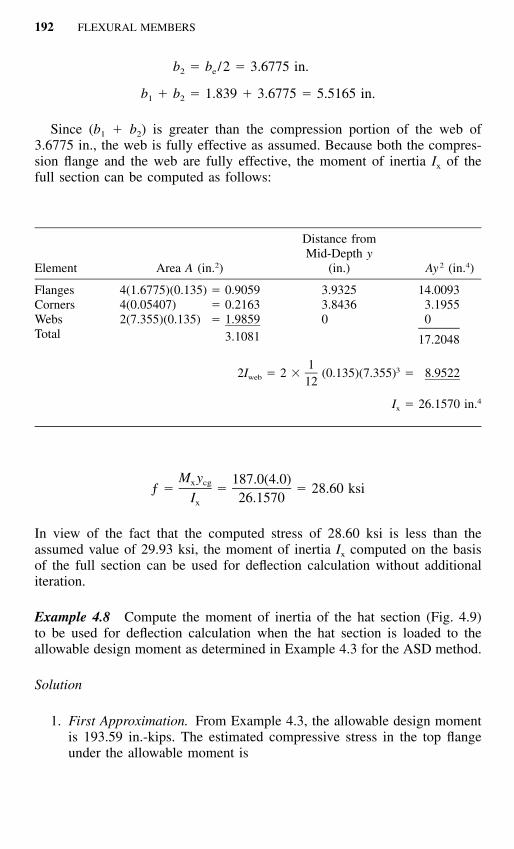
Since (b1 � b2) is greater than the compression portion of the web of3.6775 in., the web is fully effective as assumed. Because both the compres-sion flange and the web are fully effective, the moment of inertia Ix of thefull section can be computed as follows:
Element Area A (in.2)
Distance fromMid-Depth y
(in.) Ay 2 (in.4)
FlangesCornersWebsTotal
4(1.6775)(0.135) � 0.90594(0.05407) � 0.21632(7.355)(0.135) � 1.9859
3.1081
3.93253.84360
14.00933.19550
17.2048
1 32I � 2 � (0.135)(7.355) � 8.9522web 12
4I � 26.1570 in.x
M y 187.0(4.0)x cgƒ � � � 28.60 ksiI 26.1570x
In view of the fact that the computed stress of 28.60 ksi is less than theassumed value of 29.93 ksi, the moment of inertia Ix computed on the basisof the full section can be used for deflection calculation without additionaliteration.
Example 4.8 Compute the moment of inertia of the hat section (Fig. 4.9)to be used for deflection calculation when the hat section is loaded to theallowable design moment as determined in Example 4.3 for the ASD method.
Solution
1. First Approximation. From Example 4.3, the allowable design momentis 193.59 in.-kips. The estimated compressive stress in the top flangeunder the allowable moment is

4.2 BENDING STRENGTH AND DEFLECTION 193
M y 193.59(4.487)x cgƒ � � � 24.37 ksiI 35.646x
The same stress of ƒ � 24.37 ksi will be assumed in the calculation ofthe effective design width for deflection determination.
Using Eqs. (3.45) through (3.47) and the same procedure employedin Example 4.3, the effective width bd of the stiffened compressionflange is computed as follows:
w � 14.415 in.
w / t � 137.29
k � 4.0
ƒ � 24.37 ksi
1.052 24.37� � (137.29) � 2.076 � 0.673�29,500�4
0.22� � 1 � 2.076 � 0.431� ��2.076
b � �w � 0.431(14.415) � 6.213 in.d
By using the effective width of the compression flange and assumingthe web is fully effective, the moment of inertia can be computed fromthe line elements shown in Fig. 4.10 as follows:
ElementEffective Length L
(in.)
Distance fromTop Fiber y
(in.)Ly
(in.2)Ly 2
(in.3)
12345
Total
2(1.0475) � 2.09502(0.3768) � 0.75362(9.415) � 18.83002(0.3768) � 0.7536
6.213028.6452
9.94769.86045.00000.13960.0525
20.84007.4308
94.15000.10520.3262
122.8522
207.305973.2707
470.75000.01470.0171
751.3584
122.8522y � � 4.289 in.cg 28.6452

194 FLEXURAL MEMBERS
The total Ix is
1 32I� � 2 (9.415) � 139.0944� �3 122(Ly ) � 751.3584�
890.4528
2 2� L (y ) � �28.6452(4.289) � �526.9434�� � cg
3I� � 363.5094 in.x
4I � I� t � 363.5094(0.105) � 38.168 in.x x
The compressive stress in the top fiber is
M y 193.59(4.289)x cgƒ � �I 38.168x
� 21.75 ksi � the assumed value (no good)
2. Second Approximation. Assuming ƒ � 21.00 ksi and using the samevalues of w / t and k,
1.052 21.00� � (137.29) � 1.927 � 0.673�29,500�4
� � 0.460
b � �w � 6.631 in.d
ElementEffective Length
L (in.)
Distance fromTop Fiber y
(in.)Ly
(in.2)Ly 2
(in.3)
1 to 45
Total
22.43226.6310
29.0632
0.0525122.5260
0.3481
122.8741
751.34130.0183
751.3596
ycg � 4.228 in.

4.2 BENDING STRENGTH AND DEFLECTION 195
The total Ix is
2I� � 139.09443
2(Ly ) � 751.3596�890.4540
2 2� L (y ) � �29.0632(4.228) � �519.5333�� � cg
3I� � 370.9207 in.x
4I � I� t � 38.947 in.x x
M y 193.59(4.228)x cgƒ � � � 21.01 ksiI 38.947x
Since the computed value of ƒ is close to the assumed value of 21.00ksi, the moment of inertia for deflection calculation under the allowabledesign moment is 38.947 in.4 It is of interest to note that the differencebetween the I values computed from the first and second approximationsis only about 2%.
4.2.3 Lateral–Torsional Buckling Strength
Cold-formed steel flexural members, when loaded in the plane of the web,may twist and deflect laterally as well as vertically if braces are not adequatelyprovided. In the design of flexural members, the moment capacity is not onlygoverned by the section strength of the cross section as discussed in Art. 4.2.2but is also limited by the lateral buckling strength of the member. This articlecontains the design methods for determining the lateral buckling strength ofsingly, doubly, and point-symmetric sections according to the actual numberand location of braces. The design of braces is discussed in Art. 4.4.
4.2.3.1 Doubly and Singly Symmetric Sections. When a simply supported,locally stable I-beam is subject to a pure moment M as shown in Fig. 4.23,the following differential equations for the lateral–torsional buckling of sucha beam are given by Galambos in Ref. 2.45:
ivEI u � M�� � 0 (4.23)y
1vEC � � GJ�� � Mu� � 0 (4.24)w
where M � pure bending momentE � modulus of elasticity

196 FLEXURAL MEMBERS
Figure 4.23 Simply supported beam subjected to end momens.
G � shear modulus � E /2(1 � �)Iy � moment of inertia about y axis
Cw � warping constant of torsion of the cross section (see AppendixB)
J � St. Venant torsion constant of cross section approximately deter-mined by 1 3– b t3 i i
u � deflection of shear center in x direction� � angle of twist
The primes indicate differentiation with respect to z.Considering the simply supported condition, the end sections cannot deflect
or twist; they are free to warp, and no end moment exists about the y axis.The boundary conditions are
u(0) � u(L) � �(0) � �(L) � 0 (4.25)
u�(0) � u�(L) � ��(0) � ��(L) � 0 (4.26)
The solution of Eqs. (4.23) and (4.24) gives the following equation for thecritical lateral buckling moment:
2 2n n ECwM � EI GJ 1 � (4.27)� �cr y 2�L GJL
where L is the span length and n � 1, 2, 3, . . . .The deflected shape of the beam is
nz� � C sin (4.28)� �L
and the lateral deflection u can be determined by
2CML sin(nz /L)u � (4.29)2 2n EIy
The deflection history of the I-beam is shown in Fig. 4.24. When M � Mcr

4.2 BENDING STRENGTH AND DEFLECTION 197
Figure 4.24 Positions of I-beam after lateral buckling.
and M � Mcr but lateral buckling has not yet occurred, the beam deflects inthe y direction. The vertical deflection v can be obtained from Eq. (4.30) forin-plane bending,
EI v� � � M (4.30)x
Solving Eq. (4.30) and using the boundary conditions v(0) � v(L) � 0, thedeflection equation is2.45
22ML z zv � � (4.31)�� � � � �2EI L Lx
When the beam buckles laterally, the section rotates about the center of ro-tation CLB. This point is located at a distance of yLB below the shear centerof the section as determined by Eq. (4.32),
2u MLy � (4.32)LB 2 2� n EIy
From Eq. (4.27), for n � 1, the lowest critical moment for lateral bucklingof an I-beam is equal to
2 ECwM � EI GJ 1 � (4.33)� �cr y 2�L GJL
Since for I-beams (Fig. 4.25)

198 FLEXURAL MEMBERS
Figure 4.25 Dimensions of I-beam.
3 2b tdC (4.34)w 24
3b tI (4.35)y 6
Equation (4.33) can then be rewritten as follows:
22 2 2E I d yM � EI GJ � (4.36)� �cr y�L 4 L
Consequently the critical stress for lateral buckling of an I-beam subjectedto pure bending is given by
M M dcr cr� � �cr S 2Ix x2 22 I JI E Ly y
� � (4.37)� � � �� �2 2�2(L /d) 2I 2(1 � �)I dx x
where Sx is the section modulus and Ix is the moment of inertia of the fullsection about the x axis. The unpublished data of 74 tests on lateral bucklingof cold-formed steel I-sections of various shapes, spans, and loading condi-tions have demonstrated that Eq. (4.37) applies to cold-formed steel sectionswith reasonable accuracy.1.161
In Eq. (4.37) the first term under the square root represents the strengthdue to lateral bending rigidity of the beam, and the second term representsthe St. Venant torsional rigidity. For thin-walled cold-formed steel sections,the first term usually exceeds the second term considerably.
For I-beams with unequal flanges, the following equation has been derivedby Winter for the elastic lateral buckling stress.1.161,3.84,4.15
2 2 Ed 4GJL� � I � I � I 1 � (4.38)� �cr yc yt y2 2 2�2L S I Edxc y
where Sxc is the section modulus relative to the compression fiber, and Iyc and

4.2 BENDING STRENGTH AND DEFLECTION 199
Iyt are the moments of inertia of the compression and tension portions of thefull section, respectively, about the centroidal axis parallel to the web. Othersymbols were defined previously. For equal-flange sections, Iyc � Iyt � Iy /2,Eqs. (4.37) and (4.38) are identical.
As previously discussed, in Eq. (4.38) the second term under the squareroot represents the St. Venant torsional rigidity, which can be neglected with-out much loss in economy. Therefore Eq. (4.38) can be simplified as shownin Eq. (4.39) by considering Iy � Iyc � Iyt and neglecting the term of 4GJL2/2IyEd2:
2 EdIyc� � (4.39)cr 2L Sxc
Equation (4.39) was derived on the basis of a uniform bending moment.It is rather conservative for the case of unequal end moments. For this reasonit may be modified by multiplying the right-hand side by a bending coefficientCb,
1.161,3.84
2C Eb� � (4.40)cr 2L S /dIxc yc
where Cb is the bending coefficient, which can conservatively be taken asunity. During the period from 1968 to 1996, the bending coefficient wascalculated from Cb � 1.75 � 1.05(M1 /M2) � 0.3(M1 /M2)
2, but must notexceed 2.3. Here M1 is the smaller and M2 the larger bending moment at theends of the unbraced length, taken about the strong axis of the member. Theratio of end moments M1 /M2 is positive when M1 and M2 have the same sign(reverse curvature bending) and negative when they are of opposite signs(single curvature bending).
The above equation for Cb was replaced by the following equation in the1996 edition of the AISI Specification:
12.5MmaxC �b 2.5M � 3M � 4M � 3Mmax A B C
where Mmax � absolute value of maximum moment in the unbraced segmentMA � absolute value of moment at quarter point of unbraced seg-
mentMB � absolute value of moment at centerline of unbraced segmentMC � absolute value of moment at three-quarter point of unbraced
segment
This newly adopted equation for bending coefficient was derived from Ref.4.156. It can be used for various shapes of moment diagrams within the

200 FLEXURAL MEMBERS
unbraced segment and gives more accurate results for fixed-end beams andmoment diagrams which are not straight lines.
Consequently, the simplified, elastic critical moment for lateral bucklingof doubly-symmetric I-beams can be calculated from the elastic critical buck-ling stress given in Eq. (34.40) and the section modulus relative to the com-pression fiber as follows:
2C EdIb yc(M ) � � S � (4.41)cr e cr xc 2L
The above design formula is used in Sec. C3.1.2 of the 1996 edition of theAISI Specification as Eq. (C3.1.2-15).
It should be noted that Eq. (4.40) applies to elastic buckling of cold-formedsteel beams when the computed theoretical buckling stress is less than orequal to the proportional limit �pr. However, when the computed stress ex-ceeds the proportional limit, the beam behavior will be governed by inelasticbuckling. For extremely short beams, the maximum moment capacity mayreach the full plastic moment Mp for compact sections. A previous study4.16
has indicated that for wide-flange beams having an average shape factor of10/9,
M � (10/9)M � (10/9)F S (4.42)p y y x
where Mp � full plastic momentMy � yield moment, � SxFy
This means that the stress in extreme fibers may reach a hypothetical valueof (10/9)Fy when L2Sxc /dIyc 0 if we use the elastic section modulus tocompute moment.
As in the previous design approach for compression members (Ref. 1.4),the effective proportional limit (or the upper limit of the elastic buckling) maybe assumed to be equal to one-half the maximum stress,
1� � (10/9)F � 0.56F (4.43)pr y y2
As shown in Fig. 4.26, the corresponding L2Sxc /dIyc ratio for �cr � �pr is1.82ECb /Fy.
When the theoretical critical stress exceeds �pr, the critical stress for ine-lastic buckling may be represented by the following parabolic equation:

4.2 BENDING STRENGTH AND DEFLECTION 201
Figure 4.26 Maximum lateral buckling stress for I-beams.
F1 y(� ) � F A � (4.44)� � ��cr I y B �cr
where A and B are constants that can be determined by the followingconditions:
1. When L � 0,
(� ) � (10/9)F (4.45)cr I y
2. When ,2 2L S 1.8 ECxc b�
dI Fyc y
(� ) � 0.56F (4.46)cr I y
By solving Eq. (4.44), A and B are found as follows:
A � 10/9 (4.47)
B � 3.24 (4.48)
Therefore Eq. (4.44) can be rewritten as

202 FLEXURAL MEMBERS
Figure 4.27 Maximum lateral buckling moment for I-beams.
2F (L S /dI )10 1 y xc yc(� ) � F � � ��cr I y 29 3.24 C Eb (4.49)210 10 F (L S /dI )y xc yc� F 1 � � ��y 29 36 C Eb
This is the theoretical equation for lateral buckling in the inelastic range.Even though the maximum stress computed by Eq. (4.49) as shown in Fig.
4.26 is larger than Fy, a conservative approach has been used by AISI to limitthe maximum stress to Fy.
By using the inelastic critical buckling stress given in Eq. (4.49) and thesection modulus relative to the compression fiber, the inelastic critical momentfor lateral buckling of I-beams can be computed as follows:
(M ) � (� ) S � Mcr I cr I xc y (4.50)
M10 10 y� M 1 � � M� �y y9 36 (M )cr e
where My is the yield moment and (Mcr)e is the elastic critical moment definedin Eq. (4.41). Equation (4.50) is being used in Sec. C3.1.2 of the 1996 editionof the AISI Specification. It is used only for (Mcr)e � 0.56My as shown inFig. 4.27. Hill has demonstrated that the equations derived for I-sections canalso be used for channels with satisfactory accuracy.4.17
For cold-formed steel design, Eqs. (4.40) and (4.49) were used in the 1968and 1980 editions of the AISI Specification to develop the design equationsfor lateral buckling of I-beams and channels. In the 1986 and 1996 editionsof the AISI Specification, in addition to the use of Eqs. (4.41) and (4.50) fordetermining the critical moment, new design formulas for lateral buckling

4.2 BENDING STRENGTH AND DEFLECTION 203
strength were added as alternative methods. These additional equations weredeveloped from the previous study conducted by Pekoz and Winter ontorsional–flexural buckling of thin walled sections under eccentric load. TheAISI Specification also considers the effect of local buckling on lateral buck-ling strength of beams.
Specifically, Section C3.1.2 of the 1996 edition of the AISI Specificationprovides Eq. (4.51) for computing the elastic critical moment on the basis ofthe torsional–flexural buckling theory. It is used for singly and doubly sym-metric sections bending about the symmetry axis perpendicular to the web.
(M ) � C r A�� � (4.51)cr e b 0 ey t
where A � full cross-sectional area
�ey � (4.52)2 E
2(K L /r )y y y
�t � (4.53)21 ECwGJ �� �2 2Ar (K L )0 t t
Ky, Kt � effective length factors for bending about the y-axis and for twist-ing
Ly, Lt � unbraced length for bending about the y-axis and for twistingr0 � 2 2 2�r � r � xx y 0
rx, ry � radii of gyration of the cross section about the centroidal principalaxes
x0 � distance from the shear center to the centroid along the principalx-axis, taken as negative
Other terms were defined previously. For singly symmetric sections, thex-axis is the axis of symmetry oriented such that the shear center has a neg-ative x-coordinate. The basis for Eq. (4.51) is discussed by Pekoz in Ref.3.17. A comparison of Eqs. (4.41) and (4.51) shows that these two equationsgive similar results for channels having Ix � Iy.
3.17 However, for channelsections having Ix � Iy with large KyLy /ry ratios, the simplified Eq. (4.41)provides very conservative results as compared with Eq. (4.51).
For singly symmetric sections bending about the centroidal axis perpen-dicular to the symmetry axis, the elastic critical moment based on the tor-sional–flexural buckling theory can be computed by using Eq. (4.54):
2 2(M ) � C A� [j � C �j � r (� /� )] /C (4.54)cr e s ex s 0 t ex TF
where Cs � �1 for moment causing compression on the shear center sideof the centroid
Cs � �1 for moment causing tension on the shear center side of thecentroid
�ex � (4.55)2 E
2(K L /r )x x x

204 FLEXURAL MEMBERS
Figure 4.28 Elastic and inelastic critical lateral buckling moments for members bend-ing about centroidal axis perpendicular to the web.
CTF � 0.6 � 0.4(M1 /M2), where M1 is the smaller and M2 the largerbending moment at the ends of the unbraced length, and whereM1 /M2, the ratio of end moments, is positive when M1 and M2
have the same sign (reverse curvature bending) and negativewhen they are of opposite sign (single curvature bending).When the bending moment at any point within an unbracedlength is larger than that at both ends of this length, and formembers subject to combined axial load and bending moment,CTF shall be taken as unity.
Kx � effective length factor for bending about the x-axisLx � unbraced length for bending about the x-axis
j � (4.56)1 3 2� x dA � � xy dA � x� � 0
A A2ly
� y /2. See Appendix C for computation of y. (4.57)
Other terms were defined previously.The derivation of Eq. (4.54) is presented in Chap. 6 for beam-columns.
See Eqs. (6.46) and (6.50).It should be noted that Eqs. (4.51) and (4.54) can be used only when the
computed value of (Mcr)e does not exceed 0.56My, which is considered to bethe upper limit for the elastic buckling range. When the computed (Mcr)e
exceeds 0.56My, the inelastic critical moment can be computed from Eq.(4.50). The elastic and inelastic critical moments are shown in Fig. 4.28.
The above discussion dealt only with the lateral buckling strength of locallystable beams. For locally unstable beams, the interaction of the local buckling

4.2 BENDING STRENGTH AND DEFLECTION 205
TABLE 4.2 Coefficients K in Eq. (4.59)3.3
L2GJECw
Loads Acts at
Centroid Top Flange Bottom Flange
0.4 86.4 51.3 145.64 31.9 20.2 50.08 25.6 17.0 38.2
16 21.8 15.4 30.424 20.3 15.0 27.232 19.6 14.8 26.348 19.0 14.8 23.564 18.3 14.9 22.480 18.1 14.9 21.796 17.9 15.1 21.1
160 17.5 15.3 20.0240 17.4 15.6 19.3320 17.2 15.7 18.9400 17.2 15.8 18.7
of compression elements and the overall lateral buckling of beams may resultin a reduction of the lateral buckling strength of the member. The effect oflocal buckling on critical moment is considered in Sec. C3.1.2 of the 1986and 1996 editions of the AISI Specification, in which the nominal lateralbuckling strength is determined as follows:
ScM � M (4.58)� �n c Sf
where Mc � elastic or inelastic critical moment whichever is applicableSc � elastic section modulus of the effective section calculated at a
stress Mc /Sf in the extreme compression fiberSf � elastic section modulus of the full unreduced section for the
extreme compression fiber
In Eq. (4.58), the ratio of Sc /Sf is used to account for the effect of localbuckling on lateral buckling strength of beams.
The equations developed above for the uniform bending moment can alsobe used for other loading conditions with reasonable accuracy.1.161,4.18 If moreaccurate results are desired, the theoretical critical value for a concentratedload at the center of a simply supported beam can be computed as3.3
�EI GJyP � K (4.59)cr 2L
where K is a coefficient to be taken from Table 4.2 based on the parameter

206 FLEXURAL MEMBERS
TABLE 4.3 Coefficients K in Eq. (4.60)3.3
L2GJECw
Loads Acts at
Centroid Top Flange Bottom Flange
0.4 143.0 92.9 222.04 53.0 36.3 77.38 42.6 30.4 59.4
16 36.3 27.4 48.024 33.8 26.6 43.432 32.6 26.1 40.448 31.5 25.8 37.664 30.5 25.7 36.280 30.1 25.7 35.1
128 29.0 26.0 33.3200 29.0 26.4 32.1280 28.8 26.5 31.4360 28.7 26.6 31.0400 28.6 26.6 30.7
GJL2 /ECw. For symmetrical I-sections, Cw Iyd2 /4, where d is the depth ofthe section.
For a uniformly distributed load, the critical load is
�EI GJyw � K (4.60)cr 3L
where K is to be taken from Table 4.3.
4.2.3.2 Point-Symmetric Sections. Point-symmetric sections such asZ-sections with equal flanges will buckle laterally at lower strengths thandoubly and singly symmetric sections. A conservative design approach hasbeen and is being used in the AISI Specification, in which the elastic criticalmoment is taken to be one-half of those permitted for I-beams or channels.Therefore instead of using Eq. (4.51), the following equation is used fordetermining the elastic critical moment for point-symmetric Z-sections bend-ing about the centroidal axis perpendicular to the web:
C r A�� �b 0 ey t(M ) � (4.61)cr e 2
In lieu of Eq. (4.61), the following simplified equation can be used tocalculate the elastic critical moment for Z-sections:

4.2 BENDING STRENGTH AND DEFLECTION 207
2C EdIb yc(M ) � (4.62)cr e 22L
All symbols used in Eqs. (4.61) and (4.62) are defined in Art. 4.2.3.1.
4.2.3.3 AISI Design Criteria for Lateral Buckling Strength of Singly, Dou-bly, and Point-Symmetric Sections The following excerpts are adopted fromSec. C3.1.2 of the Supplement to the 1996 edition of the AISI Specification,which provide the needed design equations for computing the critical lateral–torsional buckling stress.1.333 The application of the AISI design criteria isillustrated in Examples 4.9 through 4.11.
C3.1.2.1 Lateral–Torsional Buckling Strength for Open Cross SectionMembers
For laterally unbraced segments of singly, doubly, and point-symmetric sections*subject to lateral–torsional buckling, the nominal flexural strength, Mn, shall becalculated as follows:
M � S F (4.63)n c c
� � 1.67 (ASD)b
� � 0.90 (LRFD)b
where Sc � elastic section modulus relative to the extreme compression fiber ofeffective section calculated at a stress Fc
Fc � elastic or inelastic critical lateral–torsional buckling stress calculatedas follows:
For Fe � 2.78Fy
F � F (4.64a)c y
For 2.78Fy � Fe � 0.56Fy
10 10FyF � F 1 � (4.64b)� �c y9 36Fe
For Fe � 0.56Fy
*The provisions of this Section apply to I-, Z, C- and other singly symmetric section flexuralmembers (not including multiple-web deck, U- and closed box-type members, and curved or archmembers). The provisions of this Section do not apply to laterally unbraced compression flangesof otherwise laterally stable sections. Refer to Section C3.1.3 for C- and Z-purlins in which thetension flange is attached to sheathing.

208 FLEXURAL MEMBERS
F � F (4.64c)c e
where
Fe � elastic critical lateral–torsional buckling stress calculated according to (a) or(b) below:
(a) For singly, doubly, and point-symmetric sections:
Fe � for bending about the symmetry axis (4.65)C r Ab 0 �� �ey tSƒ
Sƒ � elastic section modulus of the full unreduced section relative to theextreme compression fiberFor singly symmetric sections, x-axis is the axis of symmetry orientedsuch that the shear center has a negative x-coordinate.For point-symmetric sections, use 0.5Fe. x-axis of Z-sections is thecentroidal axis perpendicular to the web.Alternatively, Fe can be calculated using the equation given in (b) fordoubly symmetric I-sections or point-symmetric sections.
For singly symmetric sections bending about the centroidal axis perpendic-ular to the axis of symmetry:
Fe � (4.66)C A�s ex 2 2[ j � C �j � r (� /� )]s 0 t exC STF ƒ
Cs � �1 for moment causing compression on the shear center side of thecentroid
Cs � �1 for moment causing tension on the shear center side of the cen-troid
�ex � (4.67)2 E
2(K L /r )x x x
�ey � (4.68)2 E
2(K L /r )y y y
�t � (4.69)21 ECwGJ �� �2 2Ar (K L )0 t t
A � full unreduced cross-sectional area
Cb � (4.70)12..5Mmax
2.5M � 3M � 4M � 3Mmax A B C
where Mmax � absolute value of maximum moment in the unbraced segmentMA � absolute value of moment at quarter point of unbraced seg-
mentMB � absolute value of moment at centerline of unbraced segmentMC � absolute value of moment at three-quarter point of unbraced
segment
Cb is permitted to be conservatively taken as unity for all cases. For canti-levers or overhangs where the free end is unbraced, Cb shall be taken asunity. For members subject to combined compressive axial load and bending

4.2 BENDING STRENGTH AND DEFLECTION 209
moment (Section C5.2), Cb shall be taken as unity.
E � modulus of elasticity (4.71)
C � 0.6 – 0.4 (M /M )TF 1 2
where M1 is the smaller and M2 the larger bending moment at the ends ofthe unbraced length in the plane of bending, and where M1 /M2, the ratio ofend moments, is positive when M1 and M2 have the same sign (reversecurvature bending) and negative when they are of opposite sign (single cur-vature bending). When the bending moment at any point within an unbracedlength is larger than that at both ends of this length, and for members subjectto combined compressive axial load and bending moment (Section C5.2),CTF shall be taken as unity.
ro � polar radius of gyration of the full cross section about the shearcenter
� 2 2 2�r � r � xx y 0
rx, ry � radii of gyration of the full cross section about the centroidalprincipal axes
G � shear modulusKx, Ky, Kt � effective length factors for bending about the x- and y-axes, and
for twistingLx, Ly, Lt � unbraced length of compression member for bending about the
x- and y-axes, and for twistingxO � distance from the shear center to the centroid along the principal
x-axis, taken as negativeJ � St. Venant torsion constant of the cross section
CW � torsional warping constant of the cross section
j � � x0 (4.72)1 3 2� x dA � � xy dA� �
A A2Iy
(b) For I- or Z-sections bent about the centroidal axis perpendicular to the web(x-axis): In lieu of (a), the following equations may be used to evaluate Fe:
2C � EdIb ycF � for doubly symmetric I-sections (4.73a)e 2S Lf
2C � EdIb yc� for point-symmetric Z-sections (4.73b)22S Lf
d � depth of sectionL � unbraced length of the member
Iyc � moment of inertia of the compression portion of a section about thecentroidal axis of the entire section parallel to the web, using the fullunreduced section.
Other terms are defined in (a).
According to Sec. C3.1.2 of the 1996 AISI Specification, it can be seen that formembers bent about the centroidal axis perpendicular to the web, calculation of

210 FLEXURAL MEMBERS
lateral–torsional buckling strength is unnecessary when the unbraced length doesnot exceed a length, Lu, which is determined for Me � 2.78My (or Fe � 2.78Fy)(see Fig. 4.28). The following equations are given in Part II of the AISI DesignManual1.159 for computing Lu:
(a) For singly, doubly, and point-symmetric sections:
2 0.5 0.5GJ C GJ2L � � � (4.74)� � � � � �u 2C C 2C1 1 1
(1) For singly and doubly symmetric sections:
2K F S7.72 y y fC � � �1 AE C �rb y
2� ECwC �2 2(K )t
(2) For point-symmetric sections:
2K F S30.9 y y fC � � �1 AE C �rb y
2� ECwC �2 2(K )t
(b) For I- or Z-sections bent about the centroidal axis perpendicular to the web(x-axis): In lieu of (a), the following equations may be used:(1) For doubly symmetric I-sections:
0.520.36C � EdIb ycL � (4.75a)� �u F Sy f
(2) For point-symmetric Z-sections:
0.520.18C � EdIb ycL � (4.75b)� �u F Sy f
In addition, Part II of the Design Manual provides beam design charts for de-termining the nominal flexural strengths of C-sections and Z-sections with lips.These charts were prepared for Fy � 33 and 55 ksi (228 and 379 MPa) with Cb �1.0. The torsional unbraced length (KtLt) is assumed to be equal to the unbracedlength about the y-axis (KyLy).
Example 4.9 For the I-beam used in Example 4.1, what is the maximumspacing of lateral supports in order to use the nominal moment of 312.35 in.-kips determined for section strength? Assume that the I-section is to be used

4.2 BENDING STRENGTH AND DEFLECTION 211
Figure 4.29 Example 4.9
as a simple beam with a span length of 10 ft to support a uniform load (seeFig. 4.29).
Solution. In order to use the nominal moment for section strength, the max-imum spacing of lateral supports can be determined from the following equa-tion:
M (for section strength) � M (for lateral–torsional buckling strength)n n
From Eqs. (4.4) and (4.63),
S F � S Fe y c c
As shown in Fig. 4.28, when L � Lu , Mc � My (or Fc � Fy) and Se � Sc.Assume that the elastic critical moment of the I-section is determined ac-cording to Sec. C3.1.2.1 (b) of the AISI Specification. For Fc � Fy,
F � 2.78 Fe y
By substituting Eq. (4.73a) for Fe into the above expression, then
2� EC dIb yc� 2.78 Fy2S Lf
Therefore,
2L � �� EC dI / (2.78S F )b yc f y
where E � 29.5 � 103 ksiCb � 1.0 (assumed value)d � 8.0 in.
Fy � 50 ksiIyc � 0.724 in.4 (see the following calculation)
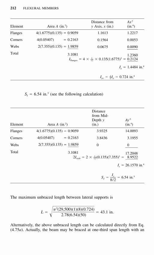
212 FLEXURAL MEMBERS
Element Area A (in.2)Distance fromy Axis, x (in.)
Ax 2
(in.4)
Flanges
Corners
Webs
Total
4(1.6775)(0.135) � 0.9059
4(0.05407) � 0.2163
2(7.355)(0.135) � 1.9859
3.1081
1.1613
0.1564
0.0675
1.2217
0.0053
0.0090
1.23601 3––I � 4 � � 0.135(1.6775) � 0.2124flanges 12
4I � 1.4484 in.y
Iyc � Iy � 0.724 in.41–2
Sf � 6.54 in.3 (see the following calculation)
Element Area A (in.2)
Distancefrom Mid-Depth y(in.)
Ay 2
(in.4)
Flanges
Corners
Webs
Total
4(1.6775)(0.135) � 0.9059
4(0.05407) � 0.2163
2(7.355)(0.135) � 1.9859
3.1081
3.9325
3.8436
0
14.0093
3.1955
0
17.20481 3––2I � 2 � (0.135)(7.355) � 8.9522web 12
4I � 26.1570 in.x
Sƒ � � 6.54 in.3Ix
8/2
The maximum unbraced length between lateral supports is
2� (29,500)(1)(8)(0.724)L � � 43.1 in. 2.78(6.54)(50)
Alternatively, the above unbraced length can be calculated directly from Eq.(4.75a). Actually, the beam may be braced at one-third span length with an
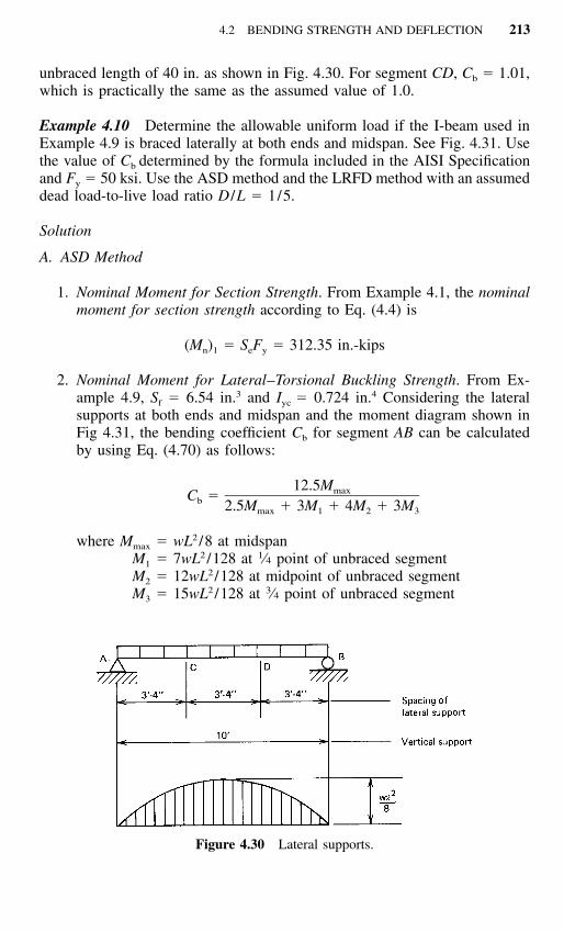
4.2 BENDING STRENGTH AND DEFLECTION 213
Figure 4.30 Lateral supports.
unbraced length of 40 in. as shown in Fig. 4.30. For segment CD, Cb � 1.01,which is practically the same as the assumed value of 1.0.
Example 4.10 Determine the allowable uniform load if the I-beam used inExample 4.9 is braced laterally at both ends and midspan. See Fig. 4.31. Usethe value of Cb determined by the formula included in the AISI Specificationand Fy � 50 ksi. Use the ASD method and the LRFD method with an assumeddead load-to-live load ratio D /L � 1/5.
Solution
A. ASD Method
1. Nominal Moment for Section Strength. From Example 4.1, the nominalmoment for section strength according to Eq. (4.4) is
(M ) � S F � 312.35 in.-kipsn 1 e y
2. Nominal Moment for Lateral–Torsional Buckling Strength. From Ex-ample 4.9, Sf � 6.54 in.3 and Iyc � 0.724 in.4 Considering the lateralsupports at both ends and midspan and the moment diagram shown inFig 4.31, the bending coefficient Cb for segment AB can be calculatedby using Eq. (4.70) as follows:
12.5MmaxC �b 2.5M � 3M � 4M � 3Mmax 1 2 3
where Mmax � wL2 /8 at midspanM1 � 7wL2 /128 at 1⁄4 point of unbraced segmentM2 � 12wL2 /128 at midpoint of unbraced segmentM3 � 15wL2 /128 at 3⁄4 point of unbraced segment

214 FLEXURAL MEMBERS
Figure 4.31 Example 4.10.
212.5(wL /8)C �b 2 2 2 22.5(wL /8) � 3(7wL /128) � 4(12wL /128) � 3(15wL /128)
� 1.30
This Cb value is less than Cb � 1.75, which was used in the 1986 AISISpecification.
Using Eq. (4.73a),2� EC dIb ycF �e 2S Lf2� (29,500)(1.30)(8)(0.724)
� � 93.11 ksi2
(6.54) 5 � 12� �0.56 F � 28.00 ksiy
2.78 F � 139.00 ksiy
Since 2.78 Fy � Fe � 0.56 Fy, from Eq. (4.64b)
10 10FyF � F 1 �� �c y9 36Fe
10 10(50.0)� (50) 1 �� �9 36(93.11)
� 47.27 ksi
Based on Eq. (4.63), the nominal moment for lateral–torsional bucklingstrength is

4.2 BENDING STRENGTH AND DEFLECTION 215
(M ) � S Fn 2 c c
in which Sc is the elastic section modulus of the effective section cal-culated at a compressive stress of f � 47.27 ksi. By using the sameprocedure illustrated in Example 4.1, Sc � 6.294 in.3 Therefore, thenominal moment for lateral–torsional buckling strength is
(M ) � (6.294)(47.27) � 297.5 in.-kipsn 2
3. Allowable Uniform Load. Because (Mn)2 � (Mn)1, lateral–torsionalbuckling strength governs the design. Use Mn � 297.5 in.-kips to de-termine the allowable moment as follows:
M � M /�a n b
� 297.5/1.67 � 178.14 in.-kips
The maximum moment at midspan is wL2 /8 ft-kips:
2wL(12) � 178.14 in.-kips
8
Then the allowable uniform load is
w � 1.188 kips/ft
It should be noted that the allowable load computed above is based on thebending moment. It should also be checked for shear, web crippling, deflec-tion, and other requirements as applicable.
B. LRFD Method
Use the same method employed above for the ASD method, the governingnominal moment for lateral–torsional buckling strength is
M � 297.5 in.-kipsn
Since the I-section has an unstiffened flange, the resistance factor as listed inTable 3.1 and discussed in Art. 4.2.1 is 0.90.
Therefore, the design moment is
� M � 0.90(297.5) � 267.75 in.-kipsb n
Based on the load combination of Eq. (3.5a), the required moment is

216 FLEXURAL MEMBERS
M � 1.4M � M � 1.4M � 5M � 6.4Mu D L D D D
where MD � bending moment due to dead loadML � bending moment due to live load
Similarly, based on the load combination of Eq. (3.5b), the required momentis
M � 1.2M � 1.6M � 1.2M � 1.6(5M ) � 9.2Mu D L D D D
A comparison of the above computations indicates that for a given member,the load combination of Eq. (3.5b) allows a smaller moment MD than the loadcombination of Eq. (3.5a). Therefore, the bending moment MD can be com-puted from Mu � �bMnas follows:
9.2M � 267.75 in.-kipsD
Therefore,
267.75M � � 29.10 in.-kipsD 9.2
M � 5M � 145.50 in.-kipsL D
The allowable moment is
M � M � M � 29.10 � 145.50 � 174.60 in.-kipsa D L
The allowable uniform load can be calculated as follows:
2wL(12) � 174.60 in.-kips
8
w � 1.164 kips/ft
It can be seen that the allowable uniform load computed on the basis ofthe LRFD method is similar to that computed from the ASD method. Thedifference is only about 2%.
Example 4.11 For the singly symmetric channel section (8 � 2 � 0.06 in.)shown in Fig. 4.32, determine the nominal moment for lateral–torsional buck-ling strength according to Sec. C3.1.2 of the Supplement to the 1996 editionof the AISI Specification. Assume that the channel is used as a simply sup-ported beam to support a concentrated load at midspan and lateral supportsare located at one-fourth of the span length. Use Fy � 33 ksi, KyLy � KtLt �2.5 ft.

4.2 BENDING STRENGTH AND DEFLECTION 217
Figure 4.32 Example 4.11.
Solution
1. Sectional Properties. By using the design formulas given in Part I ofthe AISI Design Manual, the following full section properties can becalculated:
2A � 0.706 in. x � �0.929 in.0
3S � 1.532 in. r � 3.14 in.f o
4r � 2.945 in. J � 0.000848 in.x
6r � 0.569 in. C � 2.66 in.y w
2. Elastic Critical Lateral–Torsional Buckling Stress, Fe. Because thegiven channel section is subject to a moment bending about the sym-metry axis (x-axis), the elastic critical lateral–torsional buckling stresscan be determined according to Eq. (4.65) as follows:
C r Ab 0F � �� �e ey tSf
For two central segments, the value of Cb can be computed from Eq.(4.70) as follows:
12.5MmaxC �b 2.5M � 3M � 4M � 3Mmax 1 2 3
where Mmax � PL/4 at midspanM1 � 5PL/32 at 1⁄4 point of unbraced segmentM2 � 6PL /32 at midpoint of unbraced segment
218 FLEXURAL MEMBERS
M3 � 7PL /32 at 3⁄4 point of unbraced segment
Cb �12.5(PL /4)
2.5(PL /4) � 3(5PL /32) � 4(6PL /32) � 3(7PL /32)� 1.25
�ey �2 2� E � (29,500)
� � 104.74 ksi2 2(K L /r ) (2.5 � 12/0.569)y y y
�t �21 � ECwGJ �� �2 2Ar (K L )0 t t
�1
(11,300)(0.000848)�2(0.706)(3.14)2� (29,500)(2.66)
� �2(2.5 � 12)� 125.0 ksi
Therefore, the elastic critical lateral–torsional buckling stress is
(1.25)(3.14)(0.706)F � �(104.74)(125.0) � 206.96 ksie (1.532)
3. Critical Lateral–Torsional Buckling Stress, Fc.
0.56F � 18.48 ksiy
2.78F � 91.74 ksiy
Since Fe � 2.78 Fy, then according to Eq. (4.64a)
F � Fc y
4. Nominal Moment Mn. The compressive stress in the extreme fiber is
f � F � F � 33 ksic y
By using the same procedure illustrated in Example 4.1 with the abovecompressive stress, the elastic section modulus of the effective sectionis
3S � 1.211 in.c
Based on Eq. (4.63), the nominal moment for lateral–torsional bucklingstrength is

4.2 BENDING STRENGTH AND DEFLECTION 219
M � S F � (1.211)(33) � 39.96 in.-kipsn c c
5. It should be noted that the above calculation is based on Sec. C3.1.2.1(a)of the AISI Specification.1.333 If Sec. C3.1.2.1(b) is used to compute Fe,then according to Eq. (4.73a),
2� EC dIb ycF �e 2S Lf
2� (29,500)(1.25)(8.0)(0.1145)� � 241.78 ksi2(1.532)(2.5 � 12)
Since Fe � 2.78 Fy � 91.74 ksi, then based on Eq. (4.64a),
F � Fc y
The compressive stress is also
f � F � F � 33 ksic y
The elastic section modulus of the effective section is
3S � 1.211 in.c
The nominal moment is
M � 39.96 in.-kipsn
It can be seen that for the given channel section with quarter point lateralsupports, Sec. C3.1.2.1 (a) and Sec. C3.1.2.1 (b) give the same nominal mo-ment for lateral–torsional buckling strength.
4.2.3.4 Box Sections Closed sections such as box shapes have relativelylarger torsional stiffness as compared with open sections such as I-beams,channels, and Z-sections discussed in Arts. 4.2.3.1 and 4.2.3.2. As far aslateral buckling is concerned, these closed, double-web sections are morestable than single-web open sections, and therefore any use of box sectionswill result in an economical design if lateral stability of the beam is essential.
In Ref. 4.18, Winter indicated that for box beams the bending strength isunaffected by lateral buckling even when the length-to-width ratio is as highas 100 for a steel having a yield point of 33 ksi (228 MPa).
Previous editions of the AISI Specification contained in Sec. D3.3 a con-servative design provision for lateral buckling of box beams, in which laterally

220 FLEXURAL MEMBERS
unbraced box sections can be designed without any strength reduction forlateral buckling consideration if the ratio of the unsupported length to thedistance between the webs of the section does not exceed 0.086E /Fy. In 1999,this design requirement was replaced by Sec. C3.1.2.2 in the Supplement tothe 1996 Edition of the AISI Specification.1.333
For a box section subjected to a uniform bending moment as shown in Fig.4.23, the elastic critical moment for lateral buckling is3.84
�(M ) � �EI GJcr e yL
All terms are defined in Art. 4.2.3.1, except that the torsional constant J maybe determined by the following equation for a box section having a uniformthickness:4.157
2 22b d tJ �
(b � d)
where b � midline or centerline dimension of the flanged � midline or centerline dimension of the webt � wall thickness
When a box section is subject to a nonuniform bending moment, the aboveequation for the elastic critical moment can be modified by a bending coef-ficient Cb as follows:
C �b(M ) � �EI GJ (4.76)cr e yL
Consequently, the elastic critical lateral–torsional buckling stress Fe can bedetermined by Eq. (4.77) as given in Sec. C3.1.2.2 of the Supplement to the1996 edition of the AISI Specification as follows:1.333
C �bF � �EI GJ (4.77)e yLSf
in which Sf is the elastic section modulus of the full unreduced section relativeto the extreme compression flange.
Based on Eq. (4.77), the following equation for Lu can be derived fromFe � 2.78 Fy:

4.2 BENDING STRENGTH AND DEFLECTION 221
Figure 4.33 Three possible types of supporting elastic frame for equivalent col-umn.4.19
0.36C �bL � �EI GJ (4.78)u yF Sy f
The calculation of lateral–torsional buckling strength is unnecessary when thelaterally unbraced length does not exceed Lu. Otherwise, the critical lateral–torsional buckling stress Fc should be determined from Sec. C3.1.2.1 usingthe value of Fe calculated from Eq. (4.77).
4.2.3.5 Laterally Unbraced Compression Flanges The problems dis-cussed in Arts. 4.2.3.1 and 4.2.3.2 dealt with the type of lateral buckling ofI-beams, channels, and Z-shaped sections for which the entire cross sectionrotates and deflects in the lateral direction as a unit. But this is not the casefor U-shaped beams and the combined sheet-stiffener sections as shown inFig. 4.33. For the latter, when it is loaded in such a manner that the brimsand the flanges of stiffeners are in compression, the tension flange of thebeams remains straight and does not displace laterally; only the compressionflange tends to buckle separately in the lateral direction, accompanied by out-of-plane bending of the web, as shown in Fig. 4.34, unless adequate bracingis provided.
The precise analysis of the lateral buckling of U-shaped beams is rathercomplex. The compression flange and the compression portion of the web actnot only like a column on an elastic foundation, but the problem is alsocomplicated by the weakening influence of the torsional action of the flange.For this reason, the design procedure for determining the allowable designstress for laterally unbraced compression flanges is based on the considerablesimplification of an analysis presented by Douty in Ref. 4.19. See Sec. 2 ofPart VII of the AISI design manual for cold-formed steel.1.159
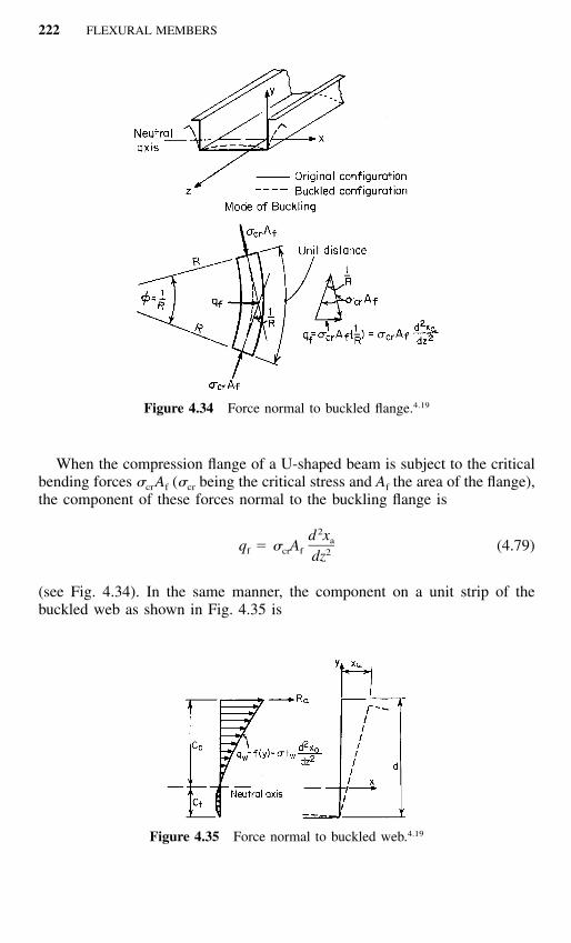
222 FLEXURAL MEMBERS
Figure 4.34 Force normal to buckled flange.4.19
Figure 4.35 Force normal to buckled web.4.19
When the compression flange of a U-shaped beam is subject to the criticalbending forces �crAf (�cr being the critical stress and Af the area of the flange),the component of these forces normal to the buckling flange is
2d xaq � � A (4.79)f cr f 2dz
(see Fig. 4.34). In the same manner, the component on a unit strip of thebuckled web as shown in Fig. 4.35 is

4.2 BENDING STRENGTH AND DEFLECTION 223
2d xq � � t (4.80)w w 2dz
As a result, the total lateral force Ra transmitted to the compression flange bythe buckled web is
2A d xweb a� (4.81)cr 212C / (3C � C ) dzc c t
where Aweb is the area of the web, and Cc and Ct are the distance from theneutral axis to the extreme compression fiber and the extreme tension fiber,respectively (Fig. 4.35).
Consequently, the equation of equilibrium of the compression flange is
4 2d x A d xa web aEI � � A � � 0 (4.82)� �f cr f4 2dz 12C / (3C � C ) dzc c t
and the corresponding nontrivial eigenvalue leads to
2� E� � (4.83)cr 2(L /r)
where
Ifr � (4.84)A � A / [12C / (3C � C )]f web c c t
which is the radius of gyration of the effective column consisting of thecompression flange and a part of the compression portion of the web havinga depth of [(3Cc � Ct) /12Cc]d, where d is the depth of the beam.
The above analysis is for the type of column supported on an elastic foun-dation where the elastic support is provided by the remaining portion of theweb and the tension flange acting together as an elastic frame. The effect oftorsional weakening in the combined flexural–torsional stability of the effec-tive column can be determined by the theorem of minimum potential en-ergy:4.19

224 FLEXURAL MEMBERS
U � V � V � U1 2 w
L1 2 2 2� � [EI (u�) � EC (��) � GJ(��) ]dzy w02
L1 2 2� � � (C u � 2C u� � C � )dz1 2 302LP Ip2 2� � (u�) � 2y u��� � (��) dz (4.85)� � � �0
02 A
where U � change in the entire potential energy of system consisting of ef-fective column and its supporting elastic frame
V1 � strain energy accumulated in bent and twisted columnV2 � strain energy of deflected supporting frame
Uw � change in potential energy of external forces acting on systemIy � moment of inertia of column about its vertical y-axisu � horizontal displacement of shear center� � rotation of columnJ � torsional constant of column
y0 � vertical distance between shear center and centroid of columnIp � polar moment of inertia of column about its shear center
Cw � warping constantC1 � 2� / (� � � � )� u � u�
C2 � 2� / (� � � � )u� u � u�
C3 � 2� / (� � � � )u u � u�
�u � horizontal displacement of shear center due to a unit load�u� � horizontal displacement of shear center due to a unit moment�� � rotation of column due to a unit moment
By solving Eq. (4.85) and applying considerable simplifications, the fol-lowing expressions can be obtained for the stability of the effective columnon an elastic foundation taking the torsional weakening of the flange intoconsideration:4.19
1. When L2 /Pe � 30,2L
P � T 1 � P (4.86)� �cr e2� Pe
2. When L2 /Pe � 30,
22 LP � T 0.6 � P (4.87)� �cr e� Pe

4.2 BENDING STRENGTH AND DEFLECTION 225
where Pcr � critical load of equivalent columnPe � Euler critical load, � �2EI /L2
� spring constant, � 1/DD � lateral deflection of column centroid due to a unit force
applied to web at level of column centroidL � unbraced length of equivalent columnT � torsional reduction factor determined as follows:
1. If L � L�,
hT � T � (4.88)0 h � 3.4y0
2. If L � L�,
L h LT � T � (4.89)� � � �� �0 L� h � 3.4y L�0
where L� �4 43 3��2I(h / t) � 3.7�I(h / t)
y0 � distance from centroid of equivalent column to its shearcenter
h � distance from tension flange to centroid of equivalent col-umn
For beams with a large distance between bracing, the following expressionfor Pcr may be used:
P � T �4EI (4.90)cr 0
From the value of Pcr given above, the equivalent slenderness ratio (L /r)eq
can then be determined as follows:
2L � E 490� k � (4.91)� � r P /A �P /Acr ceq cr c
where k is an experimental correction factor for the postbuckling strength andequals 1/1.1, and Ac is the cross-sectional area of the equivalent column.
The allowable compression stress Fa for the ASD method can be computedfrom the column formula (Chap. 5) on the basis of this equivalent slendernessratio. To obtain the allowable compression bending stress in the extreme com-pression fiber the axial stress Fa may be extrapolated linearly from theF�,b
centroid level and adjusted for the different factors of safety used for beamyielding and column buckling, that is,

226 FLEXURAL MEMBERS
Figure 4.36 Comparison between analysis and tests.4.19
� Cc cF� � F (4.92)� �b a� yb c
where �c � safety factor used for column buckling�b � safety factor used for beam yieldingyc � distance from neutral axis of beam to centroid of equivalent col-
umn
The design method developed in Ref. 4.19 has been compared with theresults of more than one hundred tests (Fig. 4.36). It has been found thatdiscrepancies are within about 30% on the conservative side and about 20%on the nonconservative side.
Based on the analysis and simplifications, the following ten-step designprocedure has been included in the AISI design manual since 1962.1.159
1. Determine the location of the neutral axis and define as the ‘‘equivalentcolumn’’ the portion of the beam from the extreme compression fiber to alevel that is a distance of [(3Cc � Ct) /12Cc]d from the extreme compressionfiber. In this expression, Cc and Ct are the distances from the neutral axis tothe extreme compression and tension fibers, respectively, and d is the depthof the section.
2. Determine the distance y0 measured parallel to the web from the cen-troid of the equivalent column to its shear center. (If the cross section of theequivalent column is of angle or T-shape, its shear center is at the intersectionof web and flange; if of channel shape, the location of the shear center isobtained from Art. 4.4. If the flanges of the channel are of unequal width,for an approximation take w as the mean of the two flange widths, or computethe location of the shear center by rigorous methods.)
3. To determine the spring constant , isolate a portion of the member 1in. (25.4 mm) long, apply a force of 0.001 kip (4.45 N) perpendicular to the

4.2 BENDING STRENGTH AND DEFLECTION 227
web at the level of the column centroid, and compute the corresponding lateraldeflection D of the centroid. Then the spring constant is
0.001 � (4.93)
D4. Calculate
hT � (4.94)0 h � 3.4y0
where h is the distance from the tension flange to the centroid of the equiv-alent column in inches.
5. a. If the flange is laterally braced at two or more points, calculate
290,000IP � (4.95)e 2L
2LC � (4.96)
Pe
3h4L� � 3.7 I (4.97)� � t
where I � moment of inertia of equivalent column about its gravity axis par-allel to web, in. 4
L � unbraced length of equivalent column, in.
If C � 30, compute
2LP � TP 1 � (4.98)� �cr e 2� Pe
If C � 30, compute
2LP � TP 0.60 � 0.635 (4.99)� �cr e Pe
In both cases, if L � L�,
T � T0
and L � L�,

228 FLEXURAL MEMBERS
T L0T � (4.100)L�
b. If the flange is braced at less than two points, compute
P � T �4EI (4.101)cr 0
6. Determine the slenderness ratio of the equivalent column,
KL 490� (4.102)� �r �P /Aeq cr c
where Ac is the cross-sectional area of the equivalent column.7. From Eqs. (5.54), (5.55), and (5.56) compute the stress Fn correspond-
ing to (KL /r)eq.8. The design compression bending stress based on previous factors of
safety is
CcF � 1.15F � F (4.103)� �b2 n yyc
where Cc � distance from neutral axis of beam to extreme compression fiberyc � distance from neutral axis of beam to centroid of equivalent col-
umn
The critical moment is Mc � Fb2Sf.Use Eq. (4.58) or Eq. (4.63) to compute Mn.
Example 4.12 Determine the design compression bending stress in the com-pression flanges (top flanges of the U-shaped section shown in Fig. 4.37.Assume that the compression flanges are laterally braced at the third pointswith unbraced lengths of 48 in. The yield point of steel is 33 ksi.
Solution
1. Location of Neutral Axis and Determination of Equivalent Column (Fig.4.37)a. Location of neutral axis

4.2 BENDING STRENGTH AND DEFLECTION 229
Figure 4.37 Example 4.12.
ElementArea A(in.2)
Distance fromTop Fiber
y (in.)Ay
(in.3)
12345
Total
2(1.0475)(0.105) � 0.22002(0.0396)(Table 4.1) � 0.07922(7.415)(0.105) � 1.55722(0.0396) � 0.79207.415(0.105) � 0.7786
2.7142
0.05250.13734.00007.86277.9475
0.01160.01096.22880.62276.187913.0619
13.0619C � � 4.812 in.c 2.7142
C � 8.0 � 4.812 � 3.188 in.t
b. Equivalent column. Based on step 1 of the procedure, the equivalentcolumn used in design is an angle section as shown in Fig. 4.38. Thedepth of the equivalent column can be determined as follows:
3C � C 3(4.812) � 3.188c t d � � 8.00 � 1.558 in� � � �12C 12(4.812)c
2. Determination of y0 (Distance from Centroid of Equivalent Column toIts Shear Center) (Fig. 4.38). The centroid of the equivalent columncan be located as follows:

230 FLEXURAL MEMBERS
Figure 4.38 Equivalent column.
Element Area A (in.2)
Distance fromTop Fiber
y (in.)Ay
(in.3)
126
Total
1.0475(0.105) � 0.11000.0396(Table 4.1) � 0.03961.2655(0.105) � 0.1329
0.2825
0.05250.13730.9253
0.00580.00550.12300.1343
0.1343y � � 0.475 in.cg 0.2825
From Appendix B it can be seen that the shear center of an angle sectionis located at the intersection of two legs. Therefore, the distance y0
between the centroid and the shear center of the equivalent column is
ty � y � � 0.475 � 0.0525 � 0.4225 in.0 cg 2
3. Calculation of Spring Constant . The spring constant can be com-puted from Eq. (4.93) as
0.001 �
D
for a portion of the member 1 in. in length. Here D is the lateral de-flection of the column centroid due to a force of 0.001 kip applied tothe web at the level of the column centroid (Fig. 4.39). Using the mo-ment-area method (Fig. 4.40), the deflection D can be computed:
3 2(7.4725) (7.4725) (7.895)D � �3 33EI � 10 2EI � 10

4.2 BENDING STRENGTH AND DEFLECTION 231
Figure 4.39 Force applied to web for computing spring constant.
Figure 4.40 Lateral deflection of equivalent column.
where E � 29.5 � 103 ksi and
1 3 �6 4I � (0.105) � 96.5 � 10 in.12
Therefore
359.50D � � 0.1263 in.3 �6 3(29.5 � 10 )(96.5 � 10 )10
1 1�3� � � � 7.918 � 103D � 10 126.3
4. Computation of T0 [Eq. (4.94)]
h 7.525T � � � 0.8400 h � 3.4y 7.525 � 3.4(0.4225)0
5. Determination of Pcr. In order to determine Pcr, we should first computethe moment of inertia of the equivalent column about its y-axis parallelto the web (Fig. 4.41) as follows:

232 FLEXURAL MEMBERS
Figure 4.41 Dimensions of equivalent column.
ElementArea A(in.2)
Distance from zaxis, x (in.)
Ax(in.3)
Ax 2
(in.4)
126
Total
0.11000.03960.1329
0.2825
0.81630.13730.0525
0.08980.00550.0070
0.1023
0.07330.00080.0004
0.0745
xcg � � 0.362 in.0.10230.2825
I values of the individual elements about their own centroidal axes par-allel to the web are
1 3I� � (0.105)(1.0475) � 0.01011 12
I� � 0.00022
I� � 0.00006
I� � I� � I� � 0.01031 2 6
2(Ax ) � 0.0745�4I � 0.0848 in.z
2 2� A (x ) � �0.2825(0.362) � �0.0370�� � cg
4I � 0.0478 in.y
and
2A � 0.2825 in.

4.2 BENDING STRENGTH AND DEFLECTION 233
Since the compression flange is braced at the third points, the values ofPe, C, and L� can be computed from Eqs. (4.95) to (4.97):
I 290,000(0.0478)P � 290,000 � � 6.016 kipse 2 2L 48
2 �3 2�L 7.918 � 10 (48)C � � � 3.032
P 6.016e
3 3h 7.5254 4L� � 3.7 I � 3.7 0.0478 � 42.61 in.� � � �� �t 0.105
Since C is less than 30 and L is greater than L�, from Ezq. (4.98),
2�LP � T P 1 �� �cr 0 e 2� Pe
�3 27.918 � 10 (48)� 0.840(6.016) 1 �� �2� (6.016)
� 0.840(6.016)(1 � 0.307) � 6.605 kips
6. Determination of (KL /r)eq for Equivalent Column [Eq. (4.102)]
KL 490�� �r �P /Aeq cr c
490� � 101.3
�6.60/0.2825
7. Determination of Compression Stress Fn. From Eq. (5.56),
2 2� E � (29,500)F � � � 28.37 ksie 2 2(KL /r) (101.3)eq
F 33y� � �c � �F 28.37e
� 1.08 � 1.5
2 2� 1.08cF � 0.658 F � 0.658 (33)� � � �n y
� 20.25 ksi
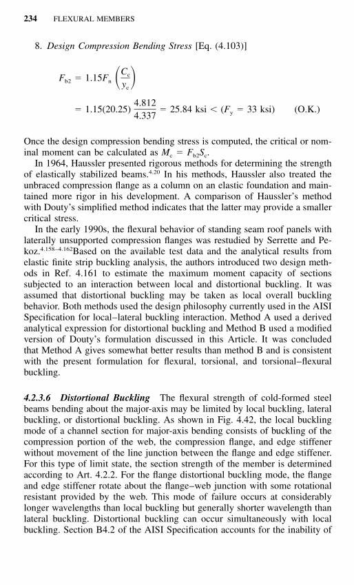
234 FLEXURAL MEMBERS
8. Design Compression Bending Stress [Eq. (4.103)]
CcF � 1.15F � �b2 n yc
4.812� 1.15(20.25) � 25.84 ksi � (F � 33 ksi) (O.K.)y4.337
Once the design compression bending stress is computed, the critical or nom-inal moment can be calculated as Mc � Fb2Sc.
In 1964, Haussler presented rigorous methods for determining the strengthof elastically stabilized beams.4.20 In his methods, Haussler also treated theunbraced compression flange as a column on an elastic foundation and main-tained more rigor in his development. A comparison of Haussler’s methodwith Douty’s simplified method indicates that the latter may provide a smallercritical stress.
In the early 1990s, the flexural behavior of standing seam roof panels withlaterally unsupported compression flanges was restudied by Serrette and Pe-koz.4.158–4.162Based on the available test data and the analytical results fromelastic finite strip buckling analysis, the authors introduced two design meth-ods in Ref. 4.161 to estimate the maximum moment capacity of sectionssubjected to an interaction between local and distortional buckling. It wasassumed that distortional buckling may be taken as local overall bucklingbehavior. Both methods used the design philosophy currently used in the AISISpecification for local–lateral buckling interaction. Method A used a derivedanalytical expression for distortional buckling and Method B used a modifiedversion of Douty’s formulation discussed in this Article. It was concludedthat Method A gives somewhat better results than method B and is consistentwith the present formulation for flexural, torsional, and torsional–flexuralbuckling.
4.2.3.6 Distortional Buckling The flexural strength of cold-formed steelbeams bending about the major-axis may be limited by local buckling, lateralbuckling, or distortional buckling. As shown in Fig. 4.42, the local bucklingmode of a channel section for major-axis bending consists of buckling of thecompression portion of the web, the compression flange, and edge stiffenerwithout movement of the line junction between the flange and edge stiffener.For this type of limit state, the section strength of the member is determinedaccording to Art. 4.2.2. For the flange distortional buckling mode, the flangeand edge stiffener rotate about the flange–web junction with some rotationalresistant provided by the web. This mode of failure occurs at considerablylonger wavelengths than local buckling but generally shorter wavelength thanlateral buckling. Distortional buckling can occur simultaneously with localbuckling. Section B4.2 of the AISI Specification accounts for the inability of
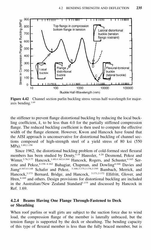
4.2 BENDING STRENGTH AND DEFLECTION 235
Figure 4.42 Channel section purlin buckling stress versus half-wavelength for major-axis bending.1.69
the stiffener to prevent flange distortional buckling by reducing the local buck-ling coefficient, k, to be less than 4.0 for the partially stiffened compressionflange. The reduced buckling coefficient is then used to compute the effectivewidth of the flange element. However, Kwon and Hancock have found thatthe AISI approach is unconservative for distortional buckling of channel sec-tions composed of high-strength steel of a yield stress of 80 ksi (550MPa).1.69,1.158
Since 1962, the distortional buckling problem of cold-formed steel flexuralmembers has been studied by Douty,4.19 Haussler, 4.20 Desmond, Pekoz andWinter,3.76,3.77 Hancock,1.69,4.163,4.164 Hancock, Rogers, and Schuster,4.165 Ser-rette and Pekoz,4.158–4.162 Buhagiar, Chapman, and Dowling4.166 Davies andJiang4.167,4.1.68 Schafer and Pekoz, 3.168,3.175,3.176,3.195 Bambach, Merrick, andHancock,3.173 Bernard, Bridge, and Hancock, 3.171,3.172 Ellifritt, Glover, andHren,4.169 and others. Design provisions for distortional buckling are includedin the Australian/New Zealand Standard1.175 and discussed by Hancock inRef. 1.69.
4.2.4 Beams Having One Flange Through-Fastened to Deckor Sheathing
When roof purlins or wall girts are subject to the suction force due to windload, the compression flange of the member is laterally unbraced, but thetension flange is supported by the deck or sheathing. The bending capacityof this type of flexural member is less than the fully braced member, but is

236 FLEXURAL MEMBERS
greater than the laterally unbraced condition because of the rotational restraintprovided by the panel-to-purlin (or girt) connection. The rotational stiffnesshas been found to be a function of the member thickness, sheet thickness,fastener type and fastener location.
In the past, the bending capacity of flexural members having the tensionflange through-fastened to deck or sheathing has been investigated by a largenumber of investigators in various countries.4.30–4.40 Based on the results ofthese studies, reduction factors for the effective yield moment have been de-veloped for simple and continuous span conditions. These factors are givenin Sec. C3.1.3 of the 1996 edition of the AISI Specification. It should benoted that the R factors for simple span C- and Z-sections up to 8.50 in. (216mm) in depth have been increased from the 1986 Specification based onFisher’s study (Ref. 4.170). In view of the fact that these reduction factorswere based on the available experimental data, their use for design is limitedonly to the conditions listed in the specification. For the convenience of read-ers, the following excerpts are adopted from the AISI Specification:
C3.1.3 Beams Having One Flange Through-Fastened to Deck or Sheathing
This section does not apply to a continuous beam for the region between inflectionpoints adjacent to a support, or to a cantilever beam.
The nominal flexural strength, Mn, of a C- or Z-section loaded in a plane parallelto the web, with the tension flange attached to deck or sheathing and with thecompression flange laterally unbraced shall be calculated as follows:
M � RS Fn e y
� � 1.67 (ASD) (4.104)b
� � 0.90 (LRFD)b
where R is obtained from Table C3.1.3-1 for simple span C- or Z-sections, and
R � 0.60 for continuous span C-sections
� 0.70 for continuous span Z-sections
Se and Fy are defined in Section C3.1.1. The reduction factor, R, shall be limitedto roof and wall systems meeting the following conditions:
(1) Member depth less than 11.5 in. (292 mm).
(2) Member flanges shall have edge stiffeners.
(3) 60 � depth/ thickness �170
(4) 2.8 � depth/flange width �4.5.
(5) 16 � flat width/ thickness of flange �43.
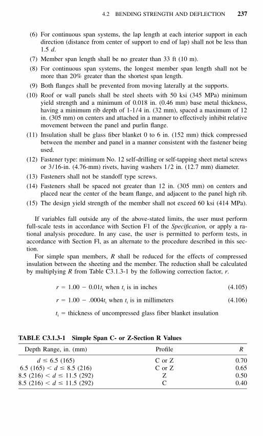
4.2 BENDING STRENGTH AND DEFLECTION 237
TABLE C3.1.3-1 Simple Span C- or Z-Section R Values
Depth Range, in. (mm) Profile R
d � 6.5 (165) C or Z 0.706.5 (165) � d � 8.5 (216) C or Z 0.65
8.5 (216) � d � 11.5 (292) Z 0.508.5 (216) � d � 11.5 (292) C 0.40
(6) For continuous span systems, the lap length at each interior support in eachdirection (distance from center of support to end of lap) shall not be less than1.5 d.
(7) Member span length shall be no greater than 33 ft (10 m).
(8) For continuous span systems, the longest member span length shall not bemore than 20% greater than the shortest span length.
(9) Both flanges shall be prevented from moving laterally at the supports.
(10) Roof or wall panels shall be steel sheets with 50 ksi (345 MPa) minimumyield strength and a minimum of 0.018 in. (0.46 mm) base metal thickness,having a minimum rib depth of 1-1/4 in. (32 mm), spaced a maximum of 12in. (305 mm) on centers and attached in a manner to effectively inhibit relativemovement between the panel and purlin flange.
(11) Insulation shall be glass fiber blanket 0 to 6 in. (152 mm) thick compressedbetween the member and panel in a manner consistent with the fastener beingused.
(12) Fastener type: minimum No. 12 self-drilling or self-tapping sheet metal screwsor 3/16-in. (4.76-mm) rivets, having washers 1/2 in. (12.7 mm) diameter.
(13) Fasteners shall not be standoff type screws.
(14) Fasteners shall be spaced not greater than 12 in. (305 mm) on centers andplaced near the center of the beam flange, and adjacent to the panel high rib.
(15) The design yield strength of the member shall not exceed 60 ksi (414 MPa).
If variables fall outside any of the above-stated limits, the user must performfull-scale tests in accordance with Section F1 of the Specification, or apply a ra-tional analysis procedure. In any case, the user is permitted to perform tests, inaccordance with Section Fl, as an alternate to the procedure described in this sec-tion.
For simple span members, R shall be reduced for the effects of compressedinsulation between the sheeting and the member. The reduction shall be calculatedby multiplying R from Table C3.1.3-1 by the following correction factor, r.
r � 1.00 � 0.01t when t is in inches (4.105)i i
r � 1.00 � .0004t when t is in millimeters (4.106)i i
t � thickness of uncompressed glass fiber blanket insulationi

238 FLEXURAL MEMBERS
4.2.5 Beams Having One Flange Fastened to a Standing SeamRoof System
Standing seam roofs were first introduced in the 1930s.4.171 Because standingseam roof panels are attached to supporting purlins with a clip that is con-cealed in the seam, this type of roof system has proved to be a cost-effectiveroof membrane due to its superior weathertightness, its ability to provideconsistent thermal performance, and low maintenance requirements with itsability to adjust to thermal expansion and contraction.4.172
For C- or Z-purlins supporting a standing seam roof system, the bendingcapacity is greater than the bending strength of an unbraced member andmaybe equal to the bending strength of a fully braced member. The bendingcapacity is governed by the nature of the loading, gravity or uplift, and thenature of the particular standing seam roof system. Due to the availability ofnumerous types of standing seam roof systems, an analytical method for com-puting positive and negative bending capacities has not been developed. Con-sequently, Section C3.1.4 was added in the 1996 edition of the AISISpecification for beams having one flange fastened to a standing seam roofsystem. In this Section, it is specified that the nominal flexural strength, Mn,of a C- or Z-section, loaded in a plane parallel to the web with the top flangesupporting a standing seam roof system shall be determined using discretepoint bracing and the provisions of Section C3.1.2.1 or shall be calculated asfollows:
M � RS F (4.107)n e y
� � 1.67 (ASD)b
� � 0.90 (LRFD)b
where
R � reduction factor determined by the ‘‘Base Test Method for Purlins Sup-porting a Standing Seam Roof System’’ provided in Appendix A of theSupplement to the 1996 edition of the Specification
Se and Fy are defined in Section C3.1.1 of the AISI Specification.
For additional design information, see Ref. 4.172, which includes detaileddiscussion and design examples using standing seam roof systems. The majoradvantage of the base test is that a simple span test may be used to predictperformance of continuous span systems for reducing experimental costs. Theconcepts for the base test was developed by T. M. Murray and his associatesat Virginia Polytechnic Institute & State University.
When standing seam roof panel systems are tested according to the ASTME1592 Standard,4.193 the new Specification Section C3.1.51.333 prescribes that
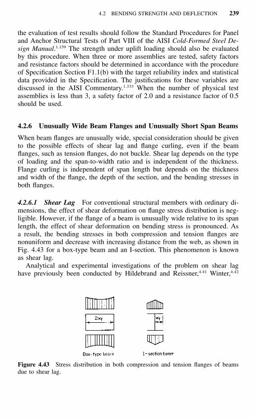
4.2 BENDING STRENGTH AND DEFLECTION 239
Figure 4.43 Stress distribution in both compression and tension flanges of beamsdue to shear lag.
the evaluation of test results should follow the Standard Procedures for Paneland Anchor Structural Tests of Part VIII of the AISI Cold-Formed Steel De-sign Manual.1.159 The strength under uplift loading should also be evaluatedby this procedure. When three or more assemblies are tested, safety factorsand resistance factors should be determined in accordance with the procedureof Specification Section F1.1(b) with the target reliability index and statisticaldata provided in the Specification. The justifications for these variables arediscussed in the AISI Commentary.1.333 When the number of physical testassemblies is less than 3, a safety factor of 2.0 and a resistance factor of 0.5should be used.
4.2.6 Unusually Wide Beam Flanges and Unusually Short Span Beams
When beam flanges are unusually wide, special consideration should be givento the possible effects of shear lag and flange curling, even if the beamflanges, such as tension flanges, do not buckle. Shear lag depends on the typeof loading and the span-to-width ratio and is independent of the thickness.Flange curling is independent of span length but depends on the thicknessand width of the flange, the depth of the section, and the bending stresses inboth flanges.
4.2.6.1 Shear Lag For conventional structural members with ordinary di-mensions, the effect of shear deformation on flange stress distribution is neg-ligible. However, if the flange of a beam is unusually wide relative to its spanlength, the effect of shear deformation on bending stress is pronounced. Asa result, the bending stresses in both compression and tension flanges arenonuniform and decrease with increasing distance from the web, as shown inFig. 4.43 for a box-type beam and an I-section. This phenomenon is knownas shear lag.
Analytical and experimental investigations of the problem on shear laghave previously been conducted by Hildebrand and Reissner,4.41 Winter,4.42

240 FLEXURAL MEMBERS
Figure 4.44 Analytical curve for determining effective width of flange of short-spanbeams.4.42
Miller,4.43 and Tate.4.44,4.45 Recently this subject has been investigated by Mal-colm and Redwood,4.46 Parr and Maggard,4.47 Van Dalen and Narasimham,4.48
Lamas and Dowling,4.49 and in Refs. 4.50 through 4.55.In their paper, Hildebrand and Reissner concluded that the amount of shear
lag depends not only on the method of loading and support and the ratio ofspan to flange width but also on the ratio of G /E and the ratio m � (3Iw �Is) / (Iw � Is), where Iw and Is are the moments of inertia of webs and of coverplates, respectively, about the neutral axis of the beam.
Based on the theory of plane stress, Winter analyzed the shear lag problemand developed tabular and graphic data,4.42 from which the effective width ofany given beam section can be obtained directly for use in design. The ratiosof the maximum and minimum bending stresses in beam flanges were com-puted and verified by the results of 11 I-beam tests. It was indicated that shearlag is important for beams with wide flanges subjected to concentrated loadson fairly short spans; the smaller the span-to-width ratio, the larger the effect.For beams supporting uniform loads, shear lag is usually negligible exceptthat the L /wf ratio is less than about 10, as shown in Fig. 4.44. Winter alsoconcluded that for a given span-to-width ratio, the effect of shear lag is prac-tically the same for box beams, I-beams, T-beams, and U-shaped beams.
Table 4.4 is a summary of the ratios of effective design width to actualwidth based on the results obtained by several investigators.4.45
In Table 4.4 wf is the width of the flange projection beyond the web forI-beams and half the distance between webs for multiple-web sections (Fig.4.43); L is the span length. It should be noted that the values obtained byHildebrand and Reissner were for G /E � 0.375 and m � 2.
As far as the design criteria are concerned, the ‘‘effective width’’ conceptused in the design of compression elements (Art. 3.5) can also be applied tothe design of beams whenever the shear lag problem is critical.
Based on the results of Winter’s investigation,4.42 design provisions forshear lag have been developed as included in Sec. B1.1(c) of the AISI Spec-

241
TABLE 4.4 Ratio of Effective Design Width to Actual Width for Wide Flanges
LoadingCondition Investigator
L /wf
6 8 10 12 16 20 30
Hildebrand Reissner 0.830 0.870 0.895 0.913 0.934 0.946
Hildebrand and Reissner 0.724 0.780 0.815 0.842 0.876 0.899
Hildebrand and Reissner 0.650 0.710 0.751 0.784 0.826 0.858
Hildebrand and Reissner 0.686 0.757 0.801 0.830 0.870 0.895 0.936
Winter 0.550 0.670 0.732 0.779 0.850 0.894 0.945
Miller 0.750
Hildebrand and Reisser 0.610 0.686 0.740 0.778 0.826 0.855 0.910
Hiildebrand and Reisser 0.830 0.897 0.936 0.957 0.977 0.985 0.991
Winter 0.850 0.896 0.928 0.950 0.974 0.984 0.995
Miller 0.875

242 FLEXURAL MEMBERS
TABLE 4.5 Maximum Allowable Ratioof Effective Design Width to Actual Widthfor Short, Wide Flanges
L /wf
Effective DesignWidth/Actual
Width
30 1.0025 0.9620 0.9118 0.8916 0.8614 0.8212 0.7810 0.73
8 0.676 0.55
ification.1.314 It is specified that when the effective span L of the beam is lessthan 30wf and when it carries one concentrated load or several loads spacedfarther apart than 2wf, the ratio of effective design width to actual width ofthe tension and compression flanges shall be limited to the value given inTable 4.5 in accordance with the L /wf ratio.
In the application of Table 4.5 the effective span length of the beam is thefull span for simple-span beams, the distance between inflection points forcontinuous beams, or twice the length of cantilever beams. The symbol wf
indicates the width of the flange projection beyond the web for I-beams andsimilar sections or half the distance between webs for multiple-web sections,including box or U-type sections (Fig. 4.43). When I-beams and similar sec-tions are stiffened by lips at outer edges, wf shall be taken as the sum of theflange projection beyond the web plus the depth of the lip.
The above tabulated ratios are also plotted in Fig. 4.44 for comparison withthe analytical values. The AISI design values are slightly larger than theanalytical results when L /wf ratios exceed about 16.
Although the above discussed provision relative to shear lag is applicableto tension and compression flanges, local buckling in compression as dis-cussed in Art. 3.5 may be a critical factor and should also be investigated.The shear lag problem is of particular importance in the analysis and designof aircraft and naval structures. In cold-formed steel building construction,however, it is infrequent that beams are so wide that they would requireconsiderable reduction of flange widths.
Example 4.13 Compute the nominal moment for the beam section shownin Fig. 4.45 if it is used to support a concentrated load on a simple span of2 ft. Assume that the minimum yield point of steel is 40 ksi.

4.2 BENDING STRENGTH AND DEFLECTION 243
Figure 4.45 Example 4.13.
Figure 4.45a.
Solution. From Fig. 4.45,
1–w � (3.25) � 0.135 � 1.490 in.f 2
30w � 44.70 in.f
L � 2 ft � 24 in.
Since L � 30wf and the beam is subject to a concentrated load, shear lagis an important factor.
Using Table 4.5 for L /wf � 16.1, the ratio of effective design width toactual width is 0.86. The effective design widths for both compression andtension flanges are
b� � 0.86 � 1.49 � 1.28 in.
See Fig. 4.45a.

244 FLEXURAL MEMBERS
To check if web is fully effective according to Art. 3.5.1.2.
f � 40(26.775/3) � 35.7 ksi (compression)1
f � 35.7 ksi (tension)2
� � f / f � �1.02 1
3k � 4 � 2[1 � (�1)] � 2[1 � (�1)] � 24
� � 1.052(5.355/0.135)�35.7/29,500/�24.
� 0.296
Since � � 0.673, � � 1.0
b � 5.355 in.e
1b � b / (3 � ) � 5.355/[3 � (�1)] � 1.339 in.e
For � �1, which is less than �0.236,
b � b /2 � 5.355/2 � 2.678 in.2 e
b � b � 1.339 � 2.678 � 4.017 in.1 2
Since (b1 � b2) is larger than the compression portion of the web of 2.6775in., the web is fully effective.
Based on the method discussed previously, the effective section modulusis
3S � 3.4 in.e
The nominal moment is
M � S F � 3.4 � 40 � 136 in.-kipsn e y
The nominal moment determined above for shear lag should be checkedfor local buckling. Since w � (3.25) � (0.1875 � 0.135) � 1.3025 in.1–2
w 1.3025� � 9.62
t 0.135
� � [1.052/�0.43](9.62)�40/29,500 � 0.568 � 0.673
b � w � 1.3025 in.
The nominal moment is

4.2 BENDING STRENGTH AND DEFLECTION 245
Figure 4.46 Example 4.14.
M � S (full section)(40)n x
In view of the fact that the nominal moment determined above for localbuckling consideration is larger than that determined for shear lag, the nom-inal moment of 136 in.-kips will govern the design.
Example 4.14 For the tubular section shown in Fig. 4.46, determine thenominal moment if the member is to be used as a simply supported beam tocarry a concentrated load at midspan. Assume that the span length is 5 ft andFy � 50 ksi.
Solution
1. Nominal Moment based on Effective Width of Compression Flange. Forthe compression flange,
w 8 � 2(3/32 � 0.06) 7.693� � � 128.2
t 0.06 0.06
Based on Eqs. (3.41) through (3.44),
� � [1.052/�k](w / t)�f /E
� [�1.052/�4](128.2)�50/29,500 � 2.776 � 0.673
� � (1 � 0.22/�) /� � (1 � 0.22/2.776)/2.776 � 0.332
b � �w � 0.332(7.693) � 2.554 in.
See Fig. 4.47.Assume that the web is fully effective, the distance ycg can be deter-
mined as follows:

246 FLEXURAL MEMBERS
Figure 4.47 Effective width of compression flange for postbuckling strength.
Figure 4.47a.
ElementArea A(in.2)
Distance fromTop Fiber y
(in.)Ay
(in.3)Ay2
(in.4)
12345
Total
2.554 � 0.06 � 0.15322 � 0.01166 � 0.0233
2 � 4.6925 � 0.06 � 0.56312 � 0.01166 � 0.0233
7.6925 � 0.06 � 0.46161.2245
0.0300.0732.5004.9274.970
0.00460.00171.40780.11482.2942
3.8231
0.000140.00133.51940.5656
11.4019
15.48717

4.2 BENDING STRENGTH AND DEFLECTION 247
ycg � � 3.122 in.�(Ay)� A
1. To check if the web is fully effective (see Fig. 4.47a).
f � 50(2.968/3.122) � 47.53 ksi (compression)1
f � 50(1.724/3.122) � 27.61 ksi (tension)2
� f / f � �27.61/47.53 � �0.5812 1
3k � 4 � 2[1 � (�0.581)] � 2[1 � (�0.581)] � 15.066
� � [1.052/�15.066](4.692/0.06)[�47.53/29,500]
� 0.851 � 0.673
� � (1 � 0.22/�) /� � (1 � 0.22/0.851)/0.851 � 0.871
b � 0.871(4.692) � 4.087 in.e
b � b / (3 � ) � 4.087/(3 � 0.581) � 1.141 in.1 e
Since � �0.236, b2 � be /2 � 4.087/2 � 2.0435 in. b1 � b2 �1.141 � 2.0435 � 3.1845 � 2.968 in. (compression portion of the web).The web is fully effective.
The total Ix is
2(Ay ) � 15.4872�1 3–I � 2 � (0.06)(4.6925) � 1.0333webs 2
2 2� A (y ) � �1.2245(3.122) � �11.9351�� � cg
4I � 4.5850 in.x
The section modulus is
I 4.5850x 3S � � � 1.469 in.x y 3.122cg
The nominal moment about the x-axis is

248 FLEXURAL MEMBERS
Figure 4.48 Effective design widths of compression and tension flanges for shearlag.
M � 1.469(50) � 73.45 in.-kipsn
2. Nominal Moment based on Shear Lag Consideration. According toFigs. 4.43 and 4.46,
8 � 2(0.06)w � � 3.94 in.f 2
L 5 � 12� � 15.23 � 30
w 3.94f
Because the L /wf ratio is less than 30, and the member carries a con-centrated load, additional consideration for shear lag is needed. UsingTable 4.5,
effective design width� 0.845
actual width
Therefore the effective design widths of compression and tensionflanges between webs are (Fig. 4.48)
0.845[8 � 2(0.06)] � 6.6586 in.
Using the full areas of webs, the moment of inertia about the x-axis is
2 2I � 4[3.22356(0.06)(2.5 � 0.03) � 0.01166(2.5 � 0.073) ]x
1 3 4––� 2 (0.06)(4.6925) � 6.046 in.12

4.2 BENDING STRENGTH AND DEFLECTION 249
Figure 4.49 Flange curling of I-beam subject to bending.4.42
and the section modulus is
3S � I /2.5 � 2.418 in.x x
The nominal moment is
M � 2.418(50) � 120.9 in.-kipsn
3. Nominal Moment for Design. From the above calculation, the nominalmoment for design is 73.45 in.-kips. Shear lag does not govern thedesign.
4.2.6.2 Flange Curling When a beam with unusually wide and thinflanges is subject to bending, the portion of the flange most remote from theweb tends to deflect toward the neutral axis. This is due to the effect oflongitudinal curvature of the beam and bending stresses in both flanges. Thissubject was studied by Winter in 1940.4.42
Let us consider an I-beam which is subject to pure bending as shown inFig. 4.49. The transverse component q of the flange force favt per unit widthcan be determined by
2f td� f t f t 2f tav av av avq � � � � (4.108)dl r EI /M Edb
where fav � average bending stress in flangest � flange thickness
d�, dl, rb � as shown in Fig. 4.49E � modulus of elasticityI � moment of inertia of beamd � depth of beam
If the value of q is considered to be a uniformly distributed load applied

250 FLEXURAL MEMBERS
on the flange, the deflection or curling at the outer edge of the flange can becomputed by the conventional method for a cantilever plate, namely,
24 4qw f wf av f 2c � � 3 (1 � ) (4.109)� � � �f 28D E t d
where cf � deflection at outer edgewf � projection of flange beyond webD � flexural rigidity of plate, � Et3 /12(1 � 2)
By substituting E � 29.5 � 103 ksi (203 GPa) and � 0.3 in Eq. (4.109),the following formula for the maximum width of an unusually wide stiffenedor unstiffened flange in tension and compression can be obtained:
1800td 100c4 fw � �f � �f dav (4.110)4
� �0.061tdE / f �100c /dav f
where cf � permissible amount of curling, in.fav � average stress in full unreduced flange width, ksi
wf, t, and d were defined previously
When members are designed by the effective design width procedure, theaverage stress equals the maximum stress times the ratio of the effectivedesign width to the actual width. Equation (4.110) is included in Sec. B1.1(b)of the AISI Specification to limit the width of unusually wide flanges.
The above formula for determining wf is derived on the basis of a constanttransverse component q. As soon as flange curling develops, the distance fromthe flange to the neutral axis becomes smaller at the outer edge of the flange.This results in the reduction of bending stresses. Therefore the values of qvary along the flange as shown in Fig. 4.49. Since the amount of cf is usuallylimited to a small percentage of the depth, the error in the determination ofwf by using Eq. (4.110) is negligible and on the conservative side.
The above approximate treatment for I-beams can also be applied to thedesign of box and U-type beams, except that for the latter the flanges of thebox beams may be regarded as simple plates freely supported at webs andthat wf is to be measured as half of the distance between webs. Using thesame analogy, one can determine the flange curling cf for box sections asfollows:

4.2 BENDING STRENGTH AND DEFLECTION 251
24 45 q(2w ) f wf av f 2c � � � 5 (1 � ) (4.111)� � � �f 2384 D E t d
A comparison of Eqs. (4.109) and (4.111) indicates that the use of Eq.(4.110), which is derived on the basis of I-beams, to determine wf for boxbeams, may result in a possible error of 13%. This is because 4�5/3 �
However, this discrepancy can be reduced if the restraint of webs and1.13.the variable values of the transverse component q are taken into consideration.
No specific values are given by the AISI Specification for the maximumpermissible amount of curling. However, it is indicated in a footnote that theamount of curling that can be tolerated will vary with different kinds ofsections and must be established by the designer. An amount of curling onthe order of 5% of the depth of the section is usually not considered excessive.
Assuming cf /d � 0.05, Eq. (4.110) can be simplified as
tdEw � 0.37f � fav
In general, the problem of flange curling is not a critical factor to limit theflange width. However, when the appearance of the section is important, theout-of-plane distortion should be closely controlled in practice.
Example 4.15 Determine the amount of curling for the compression flangeof the hat section used in Example 4.3, when the section is subjected to theallowable moment. Use the ASD method.
Solution. The curling of the compression flange of the hat section can becomputed by Eq. (4.110). In the calculation,
1–w � (15.0 � 2 � 0.105) � 7.395 in.f 2
t � 0.105 in.
d � 10.0 in.
40.69 4.934f � � � 8.34 ksiav 1.67 14.415
Using Eq. (4.110),
0.061 � 0.105 � 10 � 29,500 100c4 4f7.395 � � � 26.77�cf� �8.34 10
c � 0.0058 in.f

252 FLEXURAL MEMBERS
4.3 DESIGN OF BEAM WEBS
4.3.1 Introduction
Thin-walled cold-formed steel flexural members should not only be designedfor bending strength and deflection as discussed in Art. 4.2, but the webs ofbeams should also be designed for shear, bending, combined bending andshear, web crippling, and combined bending and web crippling. In addition,the depth of the web should not exceed the maximum value permitted bySec. B1.2 of the AISI Specification.
The maximum allowable depth-to-thickness ratio h / t for unreinforced websis limited to 200, in which h is the depth of the flat portion of the webmeasured along the plane of the web and t is the thickness of the web. Whentransverse stiffeners are provided only at supports and under concentratedloads, the maximum depth-to-thickness ratio may be increased to 260. Whenbearing stiffeners and intermediate stiffeners are used simultaneously, themaximum h / t ratio is 300. These limitations for h / t ratios are established onthe basis of the studies reported in Refs. 3.60, 4.56–4.60. If a web consistsof two or more sheets, the h / t ratios of the individual sheets shall not exceedthe maximum allowable ratios mentioned above.
The following discussions deal with the minimum requirements for trans-verse stiffeners, the design strength for shear and bending in beam webs, theload or reaction to prevent web crippling, and combinations of various typesof stresses.
4.3.2 Stiffener Requirements
In the 1996 edition of the AISI Specification, the following design require-ments for attached transverse stiffeners and intermediate stiffeners are pro-vided in Sec. B6. When the transverse stiffeners do not meet theserequirements, the load-carrying capacity for the design of such members canbe determined by tests.
a. Bearing Stiffeners. For beams having large h / t ratios, bearing stiffenersmay be used at supports and/or under concentrated loads. A nominal strength,Pn , for bearing stiffeners is the smaller of the values determined by (1) and(2) as follows:
(1) Pn � FwyAc (4.112)(2) Pn � Nominal axial load evaluated according to Art. 5.7 with Ae re-
placed by Ab
�c � 2.00 (ASD)�c � 0.85 (LRFD)
where Ac � 18t2 � As, for transverse stiffeners at interior support and underconcentrated load (4.113)
Ac � 10t2 � As, for transverse stiffeners at end support (4.114)
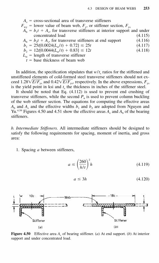
4.3 DESIGN OF BEAM WEBS 253
Figure 4.50 Effective area Ac of bearing stiffener. (a) At end support. (b) At interiorsupport and under concentrated load.
As � cross-sectional area of transverse stiffenersFwy � lower value of beam web, Fy, or stiffener section, Fys
Ab � b1t � As, for transverse stiffeners at interior support and underconcentrated load (4.115)
Ab � b2t � As, for transverse stiffeners at end support (4.116)b1 � 25t[0.0024(Lst / t) � 0.72] � 25t (4.117)b2 � 12t[0.0044(Lst / t) � 0.83] � 12t (4.118)Lst � length of transverse stiffener
t � base thickness of beam web
In addition, the specification stipulates that w / ts ratios for the stiffened andunstiffened elements of cold-formed steel transverse stiffeners should not ex-ceed and , respectively. In the above expressions, Fys1.28�E /F 0.42�E /Fys ys
is the yield point in ksi and ts the thickness in inches of the stiffener steel.It should be noted that Eq. (4.112) is used to prevent end crushing of
transverse stiffeners, while the second Pn is used to prevent column bucklingof the web stiffener section. The equations for computing the effective areasAb and Ac and the effective widths b1 and b2 are adopted from Nguyen andYu.4.59 Figures 4.50 and 4.51 show the effective areas Ac and Ab of the bearingstiffeners.
b. Intermediate Stiffeners. All intermediate stiffeners should be designed tosatisfy the following requirements for spacing, moment of inertia, and grossarea:
1. Spacing a between stiffeners,
2260a � h (4.119)� �h / t
a � 3h (4.120)

254 FLEXURAL MEMBERS
Figure 4.51 Effective area Ab of bearing stiffener. (a) At end support. (b) At interiorsupport and under concentrated load.
2. Moment of inertia Is of intermediate stiffeners with reference to an axisin the plane of the web,
h 0.7a3I � 5ht � (4.121)� �s a h
4hI � (4.122)� �s 50
3. Gross area As of intermediate stiffeners,
21 � C a (a /h)vA � � YDht (4.123)� �s 22 h (a /h) � �1 � (a /h)
where
1.53Ekv , when C � 0.8 (4.124)v2F (h/t)yC �v 1.11 Ekv� , when C � 0.8 (4.125)v�h/t Fy
5.344.00 � , when a/h � 1.0 (4.126)2(a/h)
k �v 4.00�5.34 � , when a/h � 1.0 (4.127)2(a/h)
and a � distance between transverse stiffeners, in.Y � yield point of web steel/yield point of stiffener steelD � 1.0 for stiffeners furnished in pairs
� 1.8 for single-angle stiffeners� 2.4 for single-plate stiffeners

4.3 DESIGN OF BEAM WEBS 255
Most of the above requirements for intermediate stiffeners are based onthe AISC Specification1.148 and the study reported in Ref. 4.59. The bearingstiffener requirement for residential construction is being studied by Fox andSchuster at the University of Waterloo.1.299
4.3.3 Shear
4.3.3.1 Shear Stress In the design of beams, the actual shear stress de-veloped in the cross section of the beam can be calculated by using thefollowing well-known equation:4.61
VQƒ � (4.128)v It
where ƒv � actual shear stress, ksiV � total external shear force at a section, kipsQ � statical moment of area between the extreme fiber and the par-
ticular location at which the shear stress is desired, taken aboutneutral axis, in.3
I � moment of inertia of entire cross-sectional area about neutralaxis, in.4
t � width of section where shear stress is desired, in.
Even though Eq. (4.128) gives the exact value at any location, it has beena general practice to use the average value in the gross area of the web asthe shear stress for design purposes. This average shear stress can be com-puted by using the following equation:
Vƒ � (4.129)v htw
where h � depth of the flat portion of the web measured along the plane ofthe web, in.
tw � thickness of the web, in.
The use of Eqs. (4.128) and (4.129) is illustrated in Example 4.16.
Example 4.16 Determine the shear stress distribution at the end supports ofthe uniformly loaded channel shown in Fig. 4.52. Assume that the load isapplied through the shear center of the cross section so that torsion is notinvolved.* See appendix B for a discussion of the shear center.
*When the load does not pass through the shear center, see Appendix B.

256 FLEXURAL MEMBERS
Figure 4.52 Example 4.16.
Solution
1. Exact Shear Stress Distribution Using Eq. (4.128). For simplicity, usesquare corners and midline dimensions as shown in Fig. 4.53 for com-puting the exact shear stresses at various locations of the section.Shear stress at points 1 and 4:
V � R � 1.5 kipsA
Q � Q � 01 4
VQ1(ƒ ) � � 0v 1,4 It
Shear stress at points 2 and 3:
3Q � Q � 1.4325(0.135)(6.865/2) � 0.664 in.2 3
VQ 1.5(0.664)2(ƒ ) � � � 0.941 ksiv 2,3 It 7.84(0.135)
Shear stress at point 5:
3Q � Q � 0.135(6.865/2)(6.865/4) � 1.46 in.5 2
VQ 1.5(1.46)5(ƒ ) � � � 2.07 ksiv 5 It 7.84(0.135)

4.3 DESIGN OF BEAM WEBS 257
Figure 4.53 Shear stress distribution.
2. Average Shear Stress on Beam Web by Using Eq. (4.129)
V 1.5ƒ � � � 1.65 ksiv ht 6.73(0.135)w
From the above calculation it can be seen that for the channel section usedin this example, the average shear stress of 1.65 ksi is 25% below the max-imum value of 2.07 ksi.
4.3.3.2 Shear Strength of Beam Webs
a. Shear Yielding. When a beam web with a relatively small h / t ratio issubject to shear stress, the shear capacity of the beam is probably governedby shear yielding. The maximum shear stress at the neutral axis can be com-puted by Eq. (4.130):
Fy� � (4.130)y �3
in which �y is the yield point in shear and Fy is the yield point in tension.The nominal shear strength for yielding can be determined by the shear
stress given in Eq. (4.130) and the web area, ht, as follows:

258 FLEXURAL MEMBERS
Figure 4.54 Typical shear failure pattern (h / t � 125).4.56
FyV � (ht) � 0.60F ht (4.131)� �n y�3
where Vn is the nominal shear strength, h is the depth of the flat portion ofthe web, and t is the thickness of the web.
b. Elastic Shear Buckling. For webs with large h / t ratios, the shear capacityof the web is governed by shear buckling. Figure 4.54 shows a typical patternof shear failure.4.56 Based on studies by Southwell and Skan on shear bucklingof an infinitely long plate, the plate develops a series of inclined waves, asshown in Fig. 4.55.4.62,4.63 The elastic critical shear buckling stress can becomputed by Eq. (4.132).*
2k � Ev� � (4.132)cr 2 212(1 � � )(h / t)
where kv � shear buckling coefficientE � modulus of elasticity of steel� � Poisson’s ratioh � depth of the plate
*The problem of shear buckling of plane plates has also been studied by Timoshenko and otherinvestigators. For additional information see Refs. 3.1 and 4.63.

4.3 DESIGN OF BEAM WEBS 259
Figure 4.55 Shear buckling of infinitely long plate.4.63 (a) Simply supported edges.(b) Fixed edges.
t � thickness of the plate
In Eq. (4.132), the value of kv varies with the supporting conditions andthe aspect ratio a /h (Fig. 4.56). For a long plate the value of kv was foundto be 5.34 for simple supports and 8.98 for fixed supports, as listed in Table3.2.
Substituting � � 0.3 in Eq. (4.132),
0.905k Ev� � , ksi (4.133)cr 2(h / t)
Thus if the computed theoretical value of �cr is less than the proportional limitin shear (0.8 �y), the nominal shear strength for elastic buckling can be ob-tained from Eq. (4.134):
30.905k E 0.905k Etv vV � (ht) � (4.134)n 2(h / t) h

260 FLEXURAL MEMBERS
Figure 4.56 Shear buckling stress coefficient of plates versus aspect ratio a /h.3.1
c. Shear Buckling in the Inelastic Range. For webs having moderate h / tratios, the computed theoretical value of �cr may exceed the proportional limitin shear. The theoretical value of the critical shear buckling stress should bereduced according to the change in the modulus of elasticity. Considering theinfluence of strain hardening observed in the investigation of the strength ofplate girders in shear,4.64 Basler indicated that Eq. (4.135) can be used as thereduction formula:
� � �� � (4.135)cr pr cri
where �pr � porportional limit in shear, � 0.8�y � 0.8(Fy / )�3�cri � initial critical shear buckling stress,
�2k � Ev2 212(1 � � )(h / t)
(4.136)
By substituting the values of �pr and �cri into Eq. (4.135), one can obtain Eq.(4.137) for the shear buckling stress in the inelastic range, that is,
0.64�k F Ev y� � (4.137)cr h / t
Consequently the nominal shear strength in the inelastic range can be ob-tained from Eq. (4.138):

4.3 DESIGN OF BEAM WEBS 261
0.64�k F Ev y2V � (ht) � 0.64t �k F E (4.138)n v yh / t
d. AISI Design Criteria for Shear Strength of Webs Without Holes. Based onthe foregoing discussion of shear strength of beam webs, the Supplement tothe 1996 edition of the AISI Specification includes the following design pro-visions in Sec. C3.2.1 for the ASD and LRFD methods:1.333
C3.2.1 Shear Strength of Webs without Holes
The nominal shear strength, Vn, at any section shall be calculated as follows:
(a) For h / t � 0.96 �Ek /Fv y
V � 0.60F ht (4.139a)n y
� � 1.50 (ASD)v
� � 1.0 (LRFD)v
(b) For 0.96 � h / t � 1.415�Ek /F �Ek /Fv y v y
2V � 0.64t �k F E (4.139b)n v y
� � 1.67 (ASD)v
� � 0.90 (LRFD)v
(c) For h / t � 1.415 �Ek /Fv y
2 3� Ek tv 3V � � 0.905Ek t /h (4.139c)n v212(1 � � )h
� � 1.67 (ASD)v
� � 0.90 (LRFD)v
where Vn � nominal shear strength of beamt � web thicknessh � depth of the flat portion of the web measured along the plane
of the webkv � shear buckling coefficient determined as follows:
1. For unreinforced webs, kv � 5.342. For beam webs with transverse stiffeners satisfying the re-
quirements of Section B6

262 FLEXURAL MEMBERS
when a /h � 1.0
5.34k � 4.00 � (4.140a)v 2(a /h)
when a /h � 1.0
4.00k � 5.34 � (4.140b)v 2(a /h)
where a � the shear panel length for unreinforced web element� the clear distance between transverse stiffeners for reinforced web ele-
ment.
For a web consisting of two or more sheets, each sheet shall be considered as aseparate element carrying its share of the shear force.
Prior to 1996, the AISI ASD Specification employed three different factorsof safety (i.e., 1.44 for yielding, 1.67 for inelastic buckling, and 1.71 forelastic buckling) for determining the allowable shear stresses in order to usethe same allowable values for the AISI and AISC Specifications. To simplifythe design of shear elements for using the allowable stress design method,the factor of safety for both elastic and inelastic shear buckling is taken as1.67 in the 1996 edition of the AISI Specification. The factor of safety of1.50 is used for shear yielding to provide the allowable shear stress of 0.40Fy,which has been used in steel design for a long time. The use of such a smallersafety factor of 1.50 for shear yielding is justified by long-standing use andby the minor consequences of incipient yielding in shear as compared withthose associated with yielding in tension and compression.
For the ASD method, the allowable shear stresses in webs are shown inFig. 4.57 by using E � 29,500 ksi (203 GPa). Table 4.6 gives the allowableshear stresses for Fy � 33 and 50 ksi (228 and 345 MPa). Examples 4.17through 4.19 illustrate the application of Eqs. (4.139) and (4.140).
Example 4.17 Use the ASD and LRFD methods to determine the designshear strength for the I-section used in Example 4.1. Use Fy � 50 ksi.
Solution
A. ASD Method
The depth-to-thickness ratio of each individual web element is
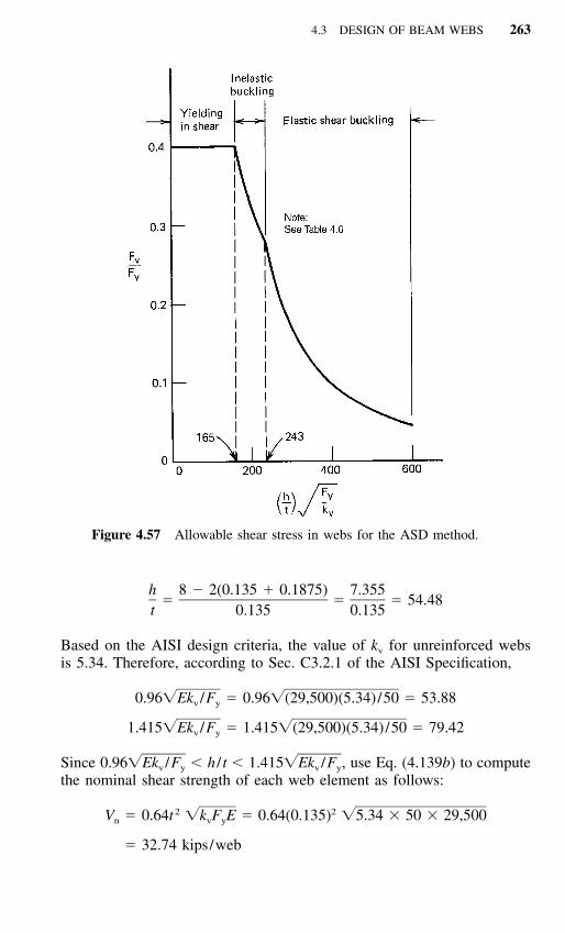
4.3 DESIGN OF BEAM WEBS 263
Figure 4.57 Allowable shear stress in webs for the ASD method.
h 8 � 2(0.135 � 0.1875) 7.355� � � 54.48
t 0.135 0.135
Based on the AISI design criteria, the value of kv for unreinforced websis 5.34. Therefore, according to Sec. C3.2.1 of the AISI Specification,
0.96�Ek /F � 0.96�(29,500)(5.34)/50 � 53.88v y
1.415�Ek /F � 1.415�(29,500)(5.34)/50 � 79.42v y
Since 0.96 � h / t � 1.415 , use Eq. (4.139b) to compute�Ek /F �Ek /Fv y v y
the nominal shear strength of each web element as follows:
2 2V � 0.64t �k F E � 0.64(0.135) �5.34 � 50 � 29,500n v y
� 32.74 kips/web
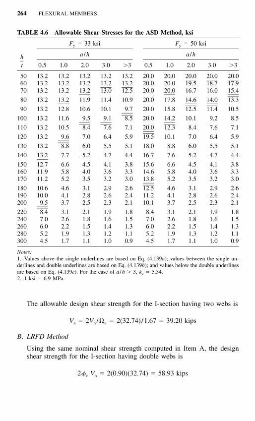
264 FLEXURAL MEMBERS
TABLE 4.6 Allowable Shear Stresses for the ASD Method, ksi
ht
Fy � 33 ksi
a /h
0.5 1.0 2.0 3.0 �3
Fy � 50 ksi
a /h
0.5 1.0 2.0 3.0 �3
50 13.2 13.2 13.2 13.2 13.2 20.0 20.0 20.0 20.0 20.060 13.2 13.2 13.2 13.2 13.2 20.0 20.0 19.5 18.7 17.970 13.2 13.2 13.2 13.0 12.5 20.0 20.0 16.7 16.0 15.4
80 13.2 13.2 11.9 11.4 10.9 20.0 17.8 14.6 14.0 13.3
90 13.2 12.8 10.6 10.1 9.7 20.0 15.8 12.5 11.4 10.5
100 13.2 11.6 9.5 9.1 8.5 20.0 14.2 10.1 9.2 8.5
110 13.2 10.5 8.4 7.6 7.1 20.0 12.3 8.4 7.6 7.1
120 13.2 9.6 7.0 6.4 5.9 19.5 10.1 7.0 6.4 5.9
130 13.2 8.8 6.0 5.5 5.1 18.0 8.8 6.0 5.5 5.1
140 13.2 7.7 5.2 4.7 4.4 16.7 7.6 5.2 4.7 4.4
150 12.7 6.6 4.5 4.1 3.8 15.6 6.6 4.5 4.1 3.8160 11.9 5.8 4.0 3.6 3.3 14.6 5.8 4.0 3.6 3.3170 11.2 5.2 3.5 3.2 3.0 13.8 5.2 3.5 3.2 3.0
180 10.6 4.6 3.1 2.9 2.6 12.5 4.6 3.1 2.9 2.6190 10.0 4.1 2.8 2.6 2.4 11.2 4.1 2.8 2.6 2.4200 9.5 3.7 2.5 2.3 2.1 10.1 3.7 2.5 2.3 2.1
220 8.4 3.1 2.1 1.9 1.8 8.4 3.1 2.1 1.9 1.8240 7.0 2.6 1.8 1.6 1.5 7.0 2.6 1.8 1.6 1.5260 6.0 2.2 1.5 1.4 1.3 6.0 2.2 1.5 1.4 1.3280 5.2 1.9 1.3 1.2 1.1 5.2 1.9 1.3 1.2 1.1300 4.5 1.7 1.1 1.0 0.9 4.5 1.7 1.1 1.0 0.9
Notes:1. Values above the single underlines are based on Eq. (4.139a); values between the single un-derlines and double underlines are based on Eq. (4.139b); and values below the double underlinesare based on Eq. (4.139c). For the case of a /h � 3, kv � 5.34.2. 1 ksi � 6.9 MPa.
The allowable design shear strength for the I-section having two webs is
V � 2V /� � 2(32.74)/1.67 � 39.20 kipsa n v
B. LRFD Method
Using the same nominal shear strength computed in Item A, the designshear strength for the I-section having double webs is
2� V � 2(0.90)(32.74) � 58.93 kipsv n

4.3 DESIGN OF BEAM WEBS 265
Example 4.18 Use the ASD and LRFD methods to determine the designshear strength for the channel section used in Example 4.2. Use Fy � 50 ksi.
Solution
A. ASD Method
For the given channel section, the depth-to-thickness ratio of the web is
h 10 � 2(0.075 � 0.09375) 9.6625� � � 128.83
t 0.075 0.075
Based on kv � 5.34 and Fy � 50 ksi
1.415�Ek /F � 1.415�(29,500)(5.34)/50 � 79.42v y
Since h / t � 1.415 , use Eq. (4.139c) to compute the nominal shear�Ek /Fv y
strength Vn as follows:
3V � 0.905Ek t /hn v
3� 0.905(29,500)(5.34)(0.075) /9.6625
� 6.22 kips
The allowable design shear strength using the ASD method for the designof the given channel section is
V � V /� � 6.22/1.67 � 3.72 kipsa n v
B. LRFD Method
Based on the same nominal shear strength computed in Item A, the designshear strength using the LRFD method for the design of the channel sec-tion is:
� V � (0.90)(6.22) � 5.60 kipsv n
Example 4.19 Use the ASD and LRFD methods to determine the designshear strength for the hat section used in Example 4.3. Use Fy � 50 ksi.
Solution
A. ASD Method
The depth-to-thickness ratio of the web is

266 FLEXURAL MEMBERS
h 10 � 2(0.105 � 0.1875) 9.415� � � 89.67
t 0.105 0.105
Based on kv � 5.34 and Fy � 50 ksi,
1.415�Ek /F � 1.415�(29,500)(5.34)/50 � 79.42v y
Since h / t � 1.415 , use Eq. (4.139c) to compute the nominal shear�Ek /Fv y
strength, Vn, for the hat section having two webs as follows:
3V � 2(0.905)Ek t /hn v
3� 2(0.905)(29,500)(5.34)(0.105) /9.415
� 35.06 kips
The allowable design shear strength using the ASD method for the design ofthe hat section is
V � V /� � 35.06/1.67 � 20.99 kipsa n v
B. LRFD Method
Based on the same nominal shear strength computed in Item A, the designshear strength using the LRFD method for the design of the hat sectionis
� V � (0.90)(35.06) � 31.55 kipsv n
e. AISI Design Criteria for Shear Strength of C-Section Webs with Holes.When holes are present in beam webs, the effect of web perforation on thereduction of shear strength of C-sections was investigated in the 1990s byShan et al.,3.184,3.197 Schuster et al.,3.187 and Eiler.3.192 In these studies, threehole geometries (rectangular hole with corner fillets, circular hole, anddiamond-shape hole) were considered in the test programs. Based on theresults of research findings, the following Sec. C3.2.2 was added in the Sup-plement to the 1996 edition of the AISI Specification in 1999.1.333
C3.2.2 Shear Strength of C-Section Webs with Holes
These provisions shall be applicable within the following limits:
1. do /h � 0.7
2. h / t � 200
3. holes centered at mid-depth of the web
4. clear distance between holes � 18 in. (457 mm)

4.3 DESIGN OF BEAM WEBS 267
5. for non-circular holes, corner radii � 2 t
6. for non-circular holes, do � 2.5 in. (64 mm) and b � 4.5 in. (114 mm)
7. circular hole diameter � 6 in. (152 mm)
8. do � 9/16 in. (14 mm)
The nominal shear strength, Vn, determined by Section C3.2.1 shall be multipliedby qs:
when c / t � 54
q � 1.0 (4.141a)s
when 5 � c / t � 54
q � c / (54 t) (4.141b)s
where
c � h /2 � d /2.83 for circular holes (4.142a)o
� h /2 � d /2 for non-circular holes (4.142b)o
d � depth of web holeo
b � length of web hole
h � depth of flat portion of the web measured
along the plane of the web
Similar as Sec. B2.4 of the AISI Specification (Art. 3.6.2), the above designprovisions for circular and non-circular holes apply to any hole pattern thatfits within an equivalent virtual hole as shown in Figs. 3.54 and 3.55.
4.3.4 Bending
Webs of beams can buckle not only in shear but also due to the compressivestress caused by bending, for example, at the location of a maximum moment.Figure 3.27 shows a typical pattern of bending failure of beam webs.
The web buckling stress due to bending and the postbuckling strength offlat beam webs are discussed in Art. 3.5.1.2. The same article also discussesthe AISI design equations for computing the effective design depth of beamwebs.
For beam webs having relatively large depth-to-thickness ratios, the buck-ling of web elements becomes more important. The structural efficiency ofsuch beam webs can be improved by adding longitudinal stiffeners in the

268 FLEXURAL MEMBERS
Figure 4.58 Typical sections for longitudinally reinforced beam specimens.
compression portion of the web, as shown in Fig. 4.58. References 4.60, 4.65,and 4.66 present the studies made by Nguyen and Yu on the structural be-havior of longitudinally reinforced beam webs.
In Europe, the design methods for profiled sheeting and sections with stiff-eners in the flanges and webs are provided in Refs. 1.209 and 3.56.
4.3.5 Combined Bending and Shear
When high bending and high shear act simultaneously, as in cantilever beamsand at interior supports of continuous beams, the webs of beams may buckleat a lower stress than if only one stress were present without the other. Suchwebs must be safeguarded against buckling due to this combined bending andshear.
The critical combination of bending and shear stresses in disjointed flatrectangular plates has been studied by Timoshenko.3.2 Figure 4.59 shows theinteraction between ƒb/ƒcr and � /�cr, in which ƒb is the actual computed bend-ing stress, ƒcr is the theoretical buckling stress in pure bending, � is the actualcomputed shear stress, and �cr is the theoretical buckling stress in pure shear.It can be seen from Fig. 4.59 that for a /h ratios ranging from 0.5 to 1.0, therelationship between ƒb/ƒcr and � /�cr can be approximated by Eq. (4.143),which is a part of the unit circle:
2 2ƒ �b� � 1 (4.143)� � � �ƒ �cr cr
By using proper factors of safety, the following interaction formula has beenused for the allowable stress design of beam webs subjected to the combinedbending and shear stresses:
2 2ƒ ƒbw v� � 1 (4.144)� � � �F Fbw v

4.3 DESIGN OF BEAM WEBS 269
Figure 4.59 Interaction relationship between ƒb /ƒcr and � /�cr.4.63
where ƒbw � actual compression stress at junction of flange and web, ksiFbw � allowable compressive stress, ksi
ƒv � actual average shear stress, ksiFv � allowable shear stress, ksi
For additional information on simply supported plates under combinedshear and uniformly distributed longitudinal stresses, see Ref. 3.3.
In the past, the structural strength of beam webs subjected to a combinationof bending and shear has been studied by LaBoube and Yu.4.57,4.67 The resultsof 25 beam tests indicated that Eq. (4.144), originally developed for a dis-jointed individual sheet, would be conservative for beam webs with adequatetransverse stiffeners, for which a diagonal tension field action can be devel-oped. Based on the test results shown in Fig. 4.60, the following interactionequation was developed for beam webs with transverse stiffeners satisfyingthe requirements of Art. 4.3.2:
ƒ �b0.6 � � 1.3 (4.145)ƒ �b max max
where ƒb max � maximum computed stress governing bending�max � maximum computed stress governing shear for reinforced
web
Accordingly, the allowable stress design equation for webs reinforced withadequate transverse stiffeners can be expressed as follows:
ƒ ƒbw v0.6 � � 1.3 (4.146)� �F Fbw v
Equation (4.146) is applicable only when ƒbw/Fbw � 0.5 and ƒv/Fv � 0.7.

270 FLEXURAL MEMBERS
Figure 4.60 Interaction diagram for � /�max and ƒb /ƒb max.
For other conditions, the design of beam webs is governed by either theallowable bending stress or the allowable shear stress.
Instead of using stress ratios in Eqs. (4.144) and (4.146), the 1986 and1996 editions of the AISI Specification use strength ratios (i.e., moment ratiofor bending and force ratio for shear) for the interaction equations. The fol-lowing design criteria are included in Sec. C3.3 of the AISI Specification todetermine the strength for combined bending and shear:
C3.3 Strength for Combined Bending and Shear
C3.3.1 ASD Method
For beams with unreinforced webs, the required flexural strength, M, andrequired shear strength, V, shall satisfy the following interaction equation:
2 2� M � Vb v� � 1.0 (4.147a)� � � �M Vnxo n
For beams with transverse web stiffeners, the required flexural strength, M,and required shear strength, V, shall not exceed Mn /�b and Vn /�v, respectively.When �bM /Mnxo � 0.5 and �vV /Vn � 0.7, then M and V shall satisfy the
4.3 DESIGN OF BEAM WEBS 271
following interaction equation:
� M � Vb v0.6 � � 1.3 (4.147b)� � � �M Vnxo n
where �b � factor of safety for bending (see Section C3.1.1)�v � factor of safety for shear (see Section C3.2)Mn � nominal flexural strength when bending alone exists
Mnxo � nominal flexural strength about the centroidal x-axis determined inaccordance with Section C3.1.1
Vn � nominal shear force when shear alone exists
C3.3.2 LRFD Method
For beams with unreinforced webs, the required flexural strength, Mu, and therequired shear strength, Vu, shall satisfy the following equation:
2 2M Vu u� � 1.0 (4.148a)� � � �� M � Vb nxo v n
For beams with transverse web stiffeners, the required flexural strength, Mu, and therequired shear strength, Vu, shall not exceed �bMn and �vVn, respectively. When Mu/(�bMnxo) � 0.5 and Vu / (�nVn) � 0.7, then Mu and Vu shall satisfy the followinginteraction equation:
M Vu u0.6 � � 1.3 (4.148b)� � � �� M � Vb nxo v n
where �b � resistance factor for bending (see Section C3.1.1)�v � resistance factor for shear (see section C3.2)Mn � nominal flexural strength when bending alone exists
Mnxo � nominal flexural strength about the centroidal x-axis determined inaccordance with Section C3.1.1
Vn � nominal shear strength when shear alone exists
Figure 4.61 shows the AISI interaction formulas using the ASD methodfor the design of beam webs subjected to the combination of bending andshear. These design criteria are based on Eqs. (4.147a) and (4.147b). A recentstudy conducted by Almoney and Murray indicated that combined bendingand shear is a possible limit state for continuous lapped Z-purlin system andthat the current AISI provisions accurately predict the failure load.4.173
4.3.6 Web Crippling (Bearing)
When the end and load stiffeners are not used in thin-walled cold-formedsteel construction, the webs of beams may cripple due to the high local in-tensity of the load or reaction. Figure 4.62 shows the types of failure caused

272 FLEXURAL MEMBERS
Figure 4.61 Interaction formulas for combined bending and shear.
Figure 4.62 Web crippling of beams.1.161
by web crippling of unrestrained single webs and of restrained double webs.The web crippling of double restrained webs is also shown in Fig. 1.30.
The buckling problem of separate flat rectangular plates under locally dis-tributed edge forces has been studied by numerous investigators, includingSommerfeld,4.68 Timoshenko,4.69 Leggett,4.70 Hopkins,4.71 Yamaki,4.72 Zetlin,4.73
White and Cottingham,4.74 Khan and Walker,4.75 Khan, Johns, and Hayman,4.76
and others.3.7 Based on Refs. 4.75 and 4.76, the buckling load for the platessubjected to locally distributed edge forces as shown in Figures 4.63 and 4.64can be computed as
2 3k� EtP � (4.149)cr 212(1 � � )h
where k is the buckling coefficient depending on the ratios of N /h and a /has given in these two figures.
For steel beams having webs connected to flanges, theoretical and exper-imental investigations on web crippling under partial edge loading have been

4.3 DESIGN OF BEAM WEBS 273
Figure 4.63 Buckling coefficient k for simply supported plates subjected to two op-posite locally distributed edge forces.1.216,4.75 (Reproduced with permission from Walker,A. C. (ed.), Design and Analysis of Cold-Formed Sections, International Textbook Co.Ltd., Glasgow and London, 1975.)
Figure 4.64 Buckling coefficient k for simply supported plates subjected to one lo-cally distributed edge force.4.76
conducted by Lyse and Godfrey,4.77 Rocky, Bagchi, and El-gaaly,4.78–4.83 andBergfelt.4.84 However, the theoretical analysis of web crippling for cold-formed steel flexural members is rather complicated because it involves thefollowing factors:
1. Nonuniform stress distribution under the applied load and adjacent por-tions of the web.
2. Elastic and inelastic stability of the web element.3. Local yielding in the immediate region of load application.

274 FLEXURAL MEMBERS
4. Bending produced by eccentric load (or reaction) when it is applied onthe bearing flange at a distance beyond the curved transition of the web.
5. Initial out-of-plane imperfection of plate elements.6. Various edge restraints provided by beam flanges and interaction be-
tween flange and web elements.7. Inclined webs for decks and panels.
For these reasons, the present AISI design provisions for web crippling arebased on the extensive experimental investigations conducted at Cornell Uni-versity by Winter and Pian,4.85 and by Zetlin4.73 in the 1940s and 1950s, andat the University of Missouri-Rolla by Hetrakul and Yu in the 1970s.4.58 Inthese experimental investigations, the web crippling tests have been carriedout under the following four loading conditions for beams having single un-reinforced webs and I-beams:
1. End one-flange (EOF) loading2. Interior one-flange (IOF) loading3. End two-flange (ETF) loading4. Interior two-flange (ITF) loading
All loading conditions are illustrated in Fig. 4.65. In Fig. 4.65a and 4.65b thedistances between bearing plates were kept to no less than 1.5 times the webdepth in order to avoid the two-flange action.
4.3.6.1 Beams Having Single Unreinforced Webs In the 1950s the webcrippling strength of cold-formed steel beams having single unreinforcedwebs has been studied experimentally at Cornell University.4.73 This investi-gation included the testing of 154 specimens, of which 128 tests were on hatsections and 26 tests on U-sections. The design formulas developed from thisstudy for the web-crippling strength depend on N / t, h / t, R / t, and Fy, whereN is the actual length of the bearing, h is the depth of the beam web, R isthe inside bend radius, t is the thickness of the beam web, and Fy is the yieldpoint of the web.
In the past, numerous types of steel sections made of high-strength mate-rials have been developed for use in building construction and for other pur-poses. The design of such unusual shapes was beyond the original scope ofthe AISI design provisions, which were developed previously on the basis ofthe Cornell research. For this reason, additional web crippling tests have beenconducted in the United States4.58,4.86 and some other countries4.87–4.89 in orderto refine the design criteria.
Based on the results of 224 web crippling tests conducted at Cornell Uni-versity and the University of Missouri-Rolla, the AISI design formulas wereslightly modified in the 1980 edition of the specification. Similar equationswith minor modifications were included in Sec. C3.4.1 of the Supplement tothe 1996 edition of the AISI Specification.1.333 All design equations for de-

4.3 DESIGN OF BEAM WEBS 275
Figure 4.65 Loading conditions for web crippling tests. (a) EOF loading. (b) IOFloading. (c) ETF loading. (d ) ITF loading.
termining the nominal web crippling strength for channels, Z-sections, hatsections, square or rectangular tubes, steel decks, and panels are given inTable 4.7. Figure 4.66 shows the applications of Eqs. (4.150) to (4.154) fordifferent types of loading. It should be noted that these equations can onlybe used for unreinforced flat webs (i.e., webs without stiffeners) havingh / t � 200. N / t � 210, N /h � 3.5, R / t � 6 for beams, R / t � 7 for decks,and 45� � � � 90�. In the design equations,
C � 1.22 � 0.22k (4.155a)1
RC � 1.06 � 0.06 � 1.0 (4.155b)� �2 t
1.333C � not used in the Supplement3
C4 � 1.15 � 0.15 � 1.0 but no less than 0.5 (4.155c)R� �t
C9 � 1.0 for U.S. customary units; 6.9 for metric units (4.155d)
C� � 0.7 � 0.3 (4.156)2
�� �90

276
TABLE 4.7 Nominal Web Crippling Strength for Single Unreinforced Webs, Pn, kips(N) /web1.314,1.333
�w � 1.85 (ASD)�w � 0.75 (LRFD)
Shapes Having Single Unreinforced Webs Such as Channels, Z-Sections, Hat Sections, Tubular Members, Desks and Panels
At locations of one concentratedload or reaction acting oneither top or bottom flange,when clear distance betweenthe bearing edges of this andadjacent oppositeconcentrated loads orreacitons is greater than 1.5h
For end reactions of beams orconcentrated loads on endof cantilever when distancefrom edge of bearing toend of beam is less than1.5h (EOF)
Stiffened flangest 2kC1C4C9C�[331 � 0.61(h / t)]
� [1 � 0.01(N / t)]
Unstiffened flangest 2kC1C4C9C�[217 � 0.28(h / t)]
� [1 � 0.01(N / t)]a
(4.150)
(4.151)
For reactions and concentratedloads when distance fromedge of bearing to end ofbeam is equal to or largerthan 1.5h (IOF)
Stiffened and unstiffened flangest 2kC1C2C9C�[538 � 0.74(h / t)]
� [1 � 0.007(N / t)]b (4.152)
At locations of two oppositeconcentrated loads or of aconcentrated load and anopposite reaction actingsimultaneously on top andbottom flanges, when cleardistance between theiradjacent bearing edges isequal to or less than 1.5h
For end reactions of beams orconcentrated loads on endof cantilever when distancefrom edge of bearing toend of beam is less than1.5h (ETF)
Stiffened and unstiffened flangest 2kC1C4C9C�[244 � 0.57(h / t)]
� [1 � 0.01(N / t)] (4.153)
For reactions and concentratedloads when distance fromedge of bearing to end ofbeam is equal to or largerthan 1.5h (ITF)
Stiffened and unstiffened flangest 2kC1C2C9C�[771 � 2.26(h / t)]
� [1 � 0.0013(N / t)] (4.154)
a When N / t � 60, the factor [1 � 0.01 (N / t)] may be increased to [0.71 � 0.015 (N / t)].b When N / t � 60, the factor [1 � 0.007 (N / t)] may be increased to [0.75 � 0.011 (N / t)].

4.3 DESIGN OF BEAM WEBS 277
Figure 4.66 Application of AISI equations listed in Tables 4.7 and 4.8.1.159
Fy � yield point used in design of the web, ksi (MPa)
h � depth of the flat portion of the web measured along plane of the web,in. (mm)
k � 894 Fy /E (4.157)
t � web thickness, in. (mm)
278 FLEXURAL MEMBERS
N � actual length of bearing, in (mm). For the case of two equal andopposite concentrated loads distributed over unequal bearing lengths,the smaller value of N should be used in design
R � inside bend radius, in. (mm)
� � angle between plane of web and plane of bearing surface, � 45� butnot more than 90�
In the 1990s, additional research conducted by Bhaka, Cain, LaBoube, andYu on web crippling indicated that a Z-section having its end support flangebolted to the section’s supporting member through two 1⁄2-in. (12.7-mm) di-ameter bolts exhibits an increase in end-one-flange (EOF) web cripplingstrength.4.174,4.175 For this reason, the 1996 edition of the AISI Specificationpermits that for a Z-section having its flange bolted to the section’s end sup-port member, Eq. (4.150) may be multiplied by 1.3. This is valid only forsections meeting the following limitations: (1)h / t � 150, (2) R / t � 4, (3)cross-section base metal thickness larger than or equal to 0.06 in. (1.52 mm),and (4) support member thickness larger than or equal to 3/16 in. (4.76 mm).
In addition, for two nested Z-sections, the 1996 edition of the AISI Spec-ification permits the use of slightly different safety factor (�w � 1.80 forASD) and resistance factor (�w � 0.85 for LRFD) when evaluating the webcrippling strength for interior-one-flange loading by using Eq. (4.152). Basedon the research work conducted at the University of Wisconsin-Milwaukeeand the University of Missouri-Rolla, LaBoube, Nunnery, and Hodges indi-cated that the web crippling behavior of unreinforced two nested Z-sectionsis enhanced because of the rotational restraint exhibited by the nested Z con-figuration and the narrow range of section parameters that represented in theindustry standard sections.4.176
From Eqs. (4.150) to (4.154) it can be seen that the nominal web cripplingstrength for beams having single unreinforced webs depends on the ratios ofN / t, h / t, and R / t, the web thickness t, the design yield stress of Fy, and theweb inclination angle �. The design strengths are based on the applicablesafety factor and resistance factor. The use of a relatively small factor ofsafety against the maximum capacity obtained from tests was due to the factthat the specimens represent the lowest degree of web restraint likely to befound in practice.
In the 1996 edition of the AISI Specification, HSLAS Grades 70 and 80of A653 and A715 steels were added in Specification Sec. A3.1. These twogrades of steels have minimum yield points of 70 ksi (483 MPa) for Grade70 and 80 ksi (522 MPa) for Grade 80. Because the AISI provisions for webcrippling strengths were previously developed on the basis of the experimentalinvestigations using steels having Fy less than 44 ksi (379 MPa), Eqs. (4.150)to (4.154) were limited only to Fy � 66.5 ksi (459 MPa). When Fy exceedsthe above limit, the value of kC3 was taken as 1.34 in a footnote of the 1996

4.3 DESIGN OF BEAM WEBS 279
edition of the Specification. Recent research at the University of Missouri-Rolla indicated that the web crippling strength increased for beams using theyield point of steel exceeding 66.5 ksi (459 MPa).4.183,4.192 Based on the resultsof 262 web crippling tests using yield strength from 58.2 ksi (401 MPa) to165.1 ksi (1138 MPa), the original constant C3 used in Eqs. (4.150), (4.151),and (4.153) was replaced by C1 with the deletion of a footnote as stated inthe AISI Supplement to the 1996 Specification.1.333
Also included in the AISI 1999 Supplement is the addition of the followingnew Section C3.4.2 for web crippling strength of C-section webs withholes:1.333
C3.4.2 Web Crippling Strength of C-Section Webs with Holes
When a web hole is within the bearing length, a bearing stiffener shall be used. Forbeam webs with holes, the web crippling strength shall be computed by using Spec-ification Section C3.4.1 multiplied by the reduction factor, Rc, given in this section.
These provisions shall be applicable within the following limits:
1. do /h � 0.7
2. h / t � 2003. holes centered at mid-depth of the web
4. clear distance between holes � 18 in. (457 mm)
5. distance between the end of the member and the edge of the hold � d
6. for non-circular holes, corner radii � 2 t
7. for non-circular holes, do � 2.5 in. (64 mm) and b � 4.5 in. (114 mm)
8. circular hole diameter � 6 in. (152 mm)
9. do � 9/16 in. (14 mm)
a. For using Equations (4.150) and (4.151) when a web hole is not within thebearing length:
R � 1.01 � 0.325d /h � 0.083 x /h � 1.0c o (4.158)
N � 1 in. (25 mm)
b. For using Equation (4.152) when any portion of a web hole is not within thebearing length:
R � 0.90 � 0.047d /h � 0.053 x /h � 1.0c o (4.159)
N � 3 in. (76 mm)
where b � length of web holed � depth of cross section
do � depth of web holeh � depth of flat portion of the web measured along the plane of the
webx � nearest distance between the web hole and the edge of bearingN � bearing length

280 FLEXURAL MEMBERS
The above provisions were based on the studies conducted by Langan etal.,3.198 Uphoff,3.199 and Deshmukh3.200 for the reduction in web cripplingstrength when a hole is present in a C-section beam web. These studies in-vestigated both the end-one-flange and interior-one-flange loading conditionsfor h / t � 200 and do /h � 0.81. The reduction in web crippling strength isinfluenced primarily by the size and location of the hole represented by thedo /h and x /h ratios.
As in Specification Sections B2.4 and C3.2.2, the above design provisionsapply to any hole pattern that fits within an equivalent virtual hole as shownin Figs. 3.54 and 3.55.
The application of Eqs. (4.150) to (4.154) is illustrated in Examples 4.20and 4.21 for beam webs having single unreinforced webs without holes.
In other countries, the Australian/New Zealand Standard1.175 and the Brit-ish Standard1.194 use the similar design provisions as the AISI Specification.In Canada, the Canadian Standard, CSA Standard S136-94, uses the followingformat for determining the web crippling strength:1.177,4.177,4.178
2P � Ct F (sin�)(1 � C �R*)(1 � C �N*)(1 � C �H*) (4.160)n y R N H
in which C is the web crippling coefficient, CH is the web slenderness coef-ficient, CN is the bearing length coefficient, CR is inside bend radius coeffi-cient, H* � h / t, N* � N / t, and R* � R / t. All coefficients are listed in threeseparate tables for built-up sections (I-beams), shapes having single webs,and deck sections (multiple webs). Equation (4.160) was based on the re-search conducted by Wing, Prabakaran, and Schuster at the University ofWaterloo.4.89,4.177 Similar design format is being considered by the AISI Com-mittee on Specifications for the Design of Cold-Formed Steel Structural Mem-bers at the present time (1999).
In the Swedish specification4.87 and the European recommendations,1.209 theweb crippling load for interior-one-flange loading depends on N / t, , t,�R / tFy, and the angle �. The design formula can be used for R / t � 10, 50� �� � 90�, and h / t � 170.
4.3.6.2 I-Beams having a High Degree of Restraint against Rotation ofthe Web In the 1940s, the web crippling behavior of I-beams was investi-gated by Winter and Pain at Cornell University.4.85 In this phase of study, atotal of 136 tests were performed on I-sections made of channels, as shownin Fig. 4.67. The h / t ratios of the specimens ranged from 30 to 175 and theN / t ratios varied from 7 to 77. The yield stresses of steel were from 30 to38 ksi (207 to 262 MPa). Equations (4.161) through (4.164) were developedfrom the Cornell tests.
For end one-flange loading,

4.3 DESIGN OF BEAM WEBS 281
Figure 4.67 Typical cross sections used in investigation of web crippling.4.85
2P � t F (10 � 1.25�N / t) (4.161)n y
For interior one-flange loading,
2P � t F (15 � 3.25�N / t) (4.162)n y
For end two-flange loading,
2P � t F (10 � 1.25�N / t) (4.163)n y
For interior two-flange loading
2P � t F (15 � 3.25�N / t) (4.164)n y
Additional tests on the web crippling of I-beams made of high-strengthmaterials and thinner steel sheets were conducted by Hetrakul and Yu at theUniversity of Missouri-Rolla in the 1970s.4.58 For these latter tests, the yieldstresses of steels ranged from 33 to 54 ksi (228 to 372 MPa) and the h / tratios were increased to 266. Based on the results of 230 tests reported inRefs. 4.85 and 4.58, the design formulas originally developed from the Cor-nell research have been modified as given in Table 4.8 for the I-beams havinga high degree of restraint against rotation of the web.
In Table 4.8,
Pn � nominal web crippling strength, kips/web
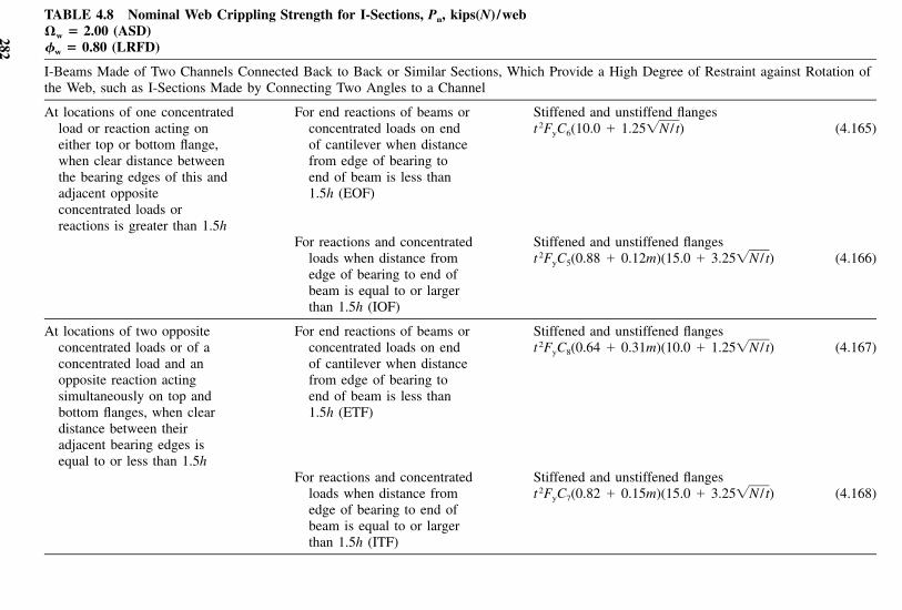
282
TABLE 4.8 Nominal Web Crippling Strength for I-Sections, Pn, kips(N) /web�w � 2.00 (ASD)�w � 0.80 (LRFD)
I-Beams Made of Two Channels Connected Back to Back or Similar Sections, Which Provide a High Degree of Restraint against Rotation ofthe Web, such as I-Sections Made by Connecting Two Angles to a Channel
At locations of one concentratedload or reaction acting oneither top or bottom flange,when clear distance betweenthe bearing edges of this andadjacent oppositeconcentrated loads orreactions is greater than 1.5h
For end reactions of beams orconcentrated loads on endof cantilever when distancefrom edge of bearing toend of beam is less than1.5h (EOF)
Stiffened and unstiffend flangest 2FyC6(10.0 � 1.25 )�N / t (4.165)
For reactions and concentratedloads when distance fromedge of bearing to end ofbeam is equal to or largerthan 1.5h (IOF)
Stiffened and unstiffened flangest 2FyC5(0.88 � 0.12m)(15.0 � 3.25 )�N / t (4.166)
At locations of two oppositeconcentrated loads or of aconcentrated load and anopposite reaction actingsimultaneously on top andbottom flanges, when cleardistance between theiradjacent bearing edges isequal to or less than 1.5h
For end reactions of beams orconcentrated loads on endof cantilever when distancefrom edge of bearing toend of beam is less than1.5h (ETF)
Stiffened and unstiffened flangest 2FyC8(0.64 � 0.31m)(10.0 � 1.25 )�N / t (4.167)
For reactions and concentratedloads when distance fromedge of bearing to end ofbeam is equal to or largerthan 1.5h (ITF)
Stiffened and unstiffened flangest 2FyC7(0.82 � 0.15m)(15.0 � 3.25 )�N / t (4.168)
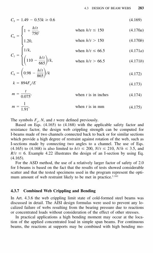
4.3 DESIGN OF BEAM WEBS 283
C � 1.49 � 0.53k � 0.65
h / t1 � ,
750C �6 �1.20,
1/k,C �7 h / t� 110 � /k,� �665
h / tC � 0.98 � /k� �8 865
k � 894F /Ey
tm � ,
0.075
1m � ,
1.91
when h / t � 150
when h / t � 150
when h / t � 66.5
when h / t � 66.5
when t is in inches
when t is in mm
(4.169)
(4.170a)
(4.170b)
(4.171a)
(4.171b)
(4.172)
(4.173)
(4.174)
(4.175)
The symbols Fy, N, and t were defined previously.Based on Eqs. (4.165) to (4.168) with the applicable safety factor and
resistance factor, the design web crippling strength can be computed forI-beams made of two channels connected back to back or for similar sectionswhich provide a high degree of restraint against rotation of the web, such asI-sections made by connecting two angles to a channel. The use of Eqs.(4.165) to (4.168) is also limited to h / t � 200, N / t � 210, N /h � 3.5, andR / t � 6. Example 4.22 illustrates the design of an I-section by using Eq.(4.165).
For the ASD method, the use of a relatively larger factor of safety of 2.0for I-beams is based on the fact that the results of tests showed considerablescatter and that the tested specimens used in the program represent the opti-mum amount of web restraint likely to be met in practice.1.161
4.3.7 Combined Web Crippling and Bending
In Art. 4.3.6 the web crippling limit state of cold-formed steel beams wasdiscussed in detail. The AISI design formulas were used to prevent any lo-calized failure of webs resulting from the bearing pressure due to reactionsor concentrated loads without consideration of the effect of other stresses.
In practical applications a high bending moment may occur at the loca-tion of the applied concentrated load in simple span beams. For continuousbeams, the reactions at supports may be combined with high bending mo-

284 FLEXURAL MEMBERS
ments and/or high shear. Under these conditions, the web crippling strengthas determined in Art. 4.3.6 may be reduced significantly due to the effectof bending moment. The interaction relationship for the combination ofbearing pressure and bending stress has been studied by numerous re-searchers.4.58,4.80,4.81,4.86–4.88,4.90–4.92 Based on the results of beam tests withcombined web crippling and bending, interaction formulas have been devel-oped for use in several design specifications.
4.3.7.1 Shapes Having Single Webs Based on the results of 49 channelspecimens and 17 hat sections tested for combined web crippling and bendingat Cornell University, the University of Missouri-Rolla,4.58 and United StatesSteel Research Laboratory,4.92 the following conclusions have been drawn inRef. 4.58.
1. For beam specimens having single unreinforced webs subjected to com-bined bending and web crippling, the presence of bending moments will no-ticeably reduce the web crippling capacity when the ratio of Mtest /Mn comp
exceeds about 0.35. Equation (4.176) provides a good correlation with thetest results, as shown in Fig. 4.68. Also shown in this figure are some testdata for web crippling combined with small bending moments.
P Mtest test1.07 � � 1.42 (4.176)P Mn comp n comp
where Ptest � maximum concentrated load or reaction in the presence ofbending moment
Pn comp � computed maximum concentrated load or reaction in the ab-sence of bending moment (Table 4.7)
Mtest � maximum bending moment at or immediately adjacent to con-centrated load or reaction
Mn comp � computed nominal flexural strength of the section if bendingonly exists
2. ASD Method When the actual shear force V in the beam is less than orequal to 40% of the nominal shear strength of the beam Vn, the presence ofshear force does not significantly reduce the web crippling load. It is expectedthat even for beams having high shear stress, the web crippling strength willnot be reduced significantly.
By using a safety factor of 1.85 for web crippling load and a safety factorof 1.67 for bending moment, the following allowable design equation (AISIEq. C3.5.1-1) can be derived from Eq. (4.176) for the ASD method:
� P � Mw b1.2 � � 1.5 (4.177)� � � �P Mn nxo

4.3 DESIGN OF BEAM WEBS 285
Figure 4.68 Graphic presentation for web crippling (IOF loading) and combined webcrippling and bending for specimens having single unreinforced webs.4.58
where �b � factor of safety for bending�w � factor of safety for web crippling
P � concentrated load or reaction in the presence of bending mo-ment
Pn � nominal web crippling strength in the absence of bending mo-ment determined in accordance with Table 4.7
M � applied bending moment at or immediately adjacent to thepoint of application of the concentrated load or reaction P
Mnxo � nominal flexural strength of the section if bending stress onlyexists, excluding lateral buckling
The relationship between the ratios of �bM /Mnxo and �wP /Pn is shown inFig. 4.69. It can be seen that Eq. (4.177) is used only for �wP /Pn � 0.417and �bM /Mnxo � 0.3. The effect of the bending moment on the web cripplingload is considered in Example 4.20.
In the AISI Specification, an exception clause is included for the interiorsupports of continuous spans using the decks and beams as shown in Fig.4.70. This is because the results of continuous beam tests of steel decks4.86
and several independent studies of individual manufacturers indicate that for

286 FLEXURAL MEMBERS
Figure 4.69 AISI ASD interaction equation for combined web crippling and bending(shapes having single unreinforced webs).
Figure 4.70 Sections used for AISI exception clauses.1.159 (a) Decks. (b) Beams.
these types of members the postbuckling behavior of beam webs at interiorsupports differs from the type of failure mode occurring under concentratedloads on single-span beams. This postbuckling strength enables the memberto redistribute the moments in continuous beams. For this reason, Eq. (4.177)may be found to be conservative for determining the load-carrying capacityof continuous spans on the basis of the conventional elastic design. If local-

4.3 DESIGN OF BEAM WEBS 287
Figure 4.71 Two-span continuous beam tests using uniform loading.
ized distortions of webs over interior supports as shown in Fig. 4.71 arepermitted, the inelastic flexural reserve capacity due to partial plastificationof beam cross section and moment redistribution may be used as discussedin Art. 4.3.8.
3. LRFD Method For the LRFD method, the AISI provisions specify thatfor shapes having single unreinforced webs subjected to a combination ofbending and concentrated load or reaction shall be designed to meet the fol-lowing requirements:
P Mu u1.07 � � 1.42 (4.176a)� � � �� P � Mw n b nxo
where �b � resistance factor for bending�w � resistance factor for web cripplingPu � required strength for the concentrated load or reaction in the
presence of bending momentPn � nominal strength for concentrated load or reaction in the absence
of bending moment (Table 4.7)Mu � required flexural strength at, or immediately adjacent to, the
point of application of the concentrated load or reaction Pu
Mnxo � nominal flexural strength about the centroidal x-axis determinedin accordance with Section C3.1.1 of the AISI Specification

288 FLEXURAL MEMBERS
Figure 4.72 Interaction between web crippling and bending for I-beam specimenshaving unreinforced webs [when h / t � 2.33/ and � � 1].4.58E /E� y
It can be seen that the above equation for using the LRFD approach is basedon Eq. (4.176). As with the ASD method, an exception clause is included forinterior support of continuous spans.
4.3.7.2 I-Beams Having a High Degree of Restraint against Rotation ofWeb In Ref. 4.58 the results of 106 beam tests conducted at Cornell4.85 andthe University of Missouri-Rolla4.94 were used to evaluate the interaction be-tween bending and web crippling for I-beams (Fig. 4.67) having a high degreeof restraint against rotation of the web. It was found that when I-beams haveh / t � 2.33/ and � � 1, the bending moment has little or no effect on�F /Ey
the web crippling load, as shown in Fig. 4.72. For I-beams having web slen-derness ratios h / t and flange flat-width ratios w / t other than the above com-bination, Eq. (4.178) can provide a good correlation with the test data asshown in Fig. 4.73:
P Mtest test0.82 � � 1.32 (4.178)P Mn comp n comp
where Ptest, Pn comp, Mtest, and Mn comp are as defined previously.

4.3 DESIGN OF BEAM WEBS 289
Figure 4.73 Interaction between web crippling and bending for I-beam specimenshaving unreinforced webs [when h / t � 2.33/ combined with � � 1, and 2.33/F /E� y
� h / t � 200 combined with any value of w / t] (IOF loading).4.58F /E� y
As far as the combination of shear force and web crippling is concerned,Ref. 4.58 concludes that when the shear ratio V /Vn � 0.80, the presence ofshear force does not affect the web crippling load significantly.
1. ASD Method By applying a safety factor of 2.0 for web crippling loadand a safety factor of 1.67 for bending moment, the following AISI designformula for I-beams can be derived from Eq. (4.178) for the ASD method:
� P � Mw b1.1 � � 1.5 (4.179)� � � �P Mn nxo
This design criterion can be used for any I-beams subjected to combinedbending and web crippling, except that when h / t � 2.33/ and � � 1,�F /Ey
the nominal web crippling strength given in Table 4.8 can be used for designwithout any reduction.
Figure 4.74 shows that the AISI interaction formula [Eq. (4.179)] is usedonly for �wP /Pn � 0.455 and �bM /Mnxo � 0.4.

290 FLEXURAL MEMBERS
Figure 4.74 AISI ASD interaction equation for combined web crippling and bending(I-beams).
2. LRFD Method For the LRFD method, the AISI provisions specify thatI-beams subjected to a combination of bending and concentrated load or re-action shall be designed to meet the following requirements:
P Mu u0.82 � � 1.32 (4.178a)� � � �� P � Mw n b nxo
All symbols were defined previously. It can be seen that the above equationfor using the LRFD method is based on Eq. (4.178). As with the ASD method,an exception clause is included to permit the use of the nominal web cripplingstrength without the use of the interaction formula.
4.3.7.3 Nested Z-Shapes In the 1996 edition of the AISI Specification,design provisions were added for nested Z-shapes. When two nested Z-shapesare subject to a combination of bending and concentrated load or reaction,these members shall be designed to meet the following requirements by usingthe ASD method:
M P 1.67� � (4.180)
M P �no n
where Mno is the nominal flexural strength for the two nested Z-sections, and� � 1.67.

4.3 DESIGN OF BEAM WEBS 291
Figure 4.75 Example 4.20.
For using the LRFD method, the Z-shapes shall be designed to meet thefollowing requirements:
M Pu u� � 1.68� (4.181)M Pno n
in which � � � 0.90. Other symbols were defined previously.Because the above two equations were derived from the experimental work
summarized in Ref. 4.176, these equations are valid only for the shapes thatmeet the following limits: h / t � 150, N / t � 140, Fy � 70 ksi (483 MPa),and R / t � 5.5. In addition, the following conditions shall also be satisfied:(1) the ends of each section shall be connected to other section by a minimumof two 1⁄2-in. (12.7-mm) diameter A307 bolts through the web, (2) the com-bined section shall be connected to the support by a minimum of two 1⁄2-in.(12.7-mm) diameter A307 bolts through the flanges, (3) the webs of the twosections shall be in contact, and (4) the ratio of the thicker-to-thinner partshall not exceed 1.3.
Example 4.20 For the channel section shown in Fig. 4.75 to be used as asimply supported beam:
1. Determine the allowable end reaction Pmax to prevent web crippling byconsidering it as a one-flange loading condition with N � 3.5 in.
2. Determine the allowable interior load to prevent web crippling by con-sidering the load as a one-flange loading condition with N � 5 in., andassuming that the applied bending moment M at the location of theinterior load is less than 30% of the allowable bending moment Mnxo /�b permitted if bending stress only exists.

292 FLEXURAL MEMBERS
3. Same as item 2, except that the applied bending moment M at thelocation of the interior load is equal to the allowable bending momentMnxo /�b.
Use Fy � 50 ksi and the ASD method.
Solution
1. Allowable End Reaction for Web Crippling (One-Flange Loading).Since
h / t � [10 � 2(0.105 � 0.1875)]/0.105 � 89.67 � 200
N / t � 3.5/0.105 � 33.33 � 210
N /h � 3.5/[10 � 2(0.105 � 0.1875)] � 0.37 � 3.5
R / t � 0.1875/0.105 � 1.786 � 6
� � 90�
k � 894(50)/29,500 � 1.515
Eqs. (4.150) through (4.154) can be used for the design of the channelsection. By using Eq. (4.150) for beams having stiffened flanges, thenominal strength to prevent web crippling at end support is
2P � t kC C C C [331 � 0.61(h / t)][1 � 0.01(N / t)]n 1 4 9 �
2� (0.105) (1.515)[1.22 � 0.22(1.515)][1.15 � 0.15(1.786)](1)2� [0.7 � 0.3(90/90) ][331 � 0.61(89.67)][1 � 0.01(33.33)]
� 4.82 kips
The allowable end reaction Pa � Pn /�w � 4.82/1.85 � 2.61 kips2. Allowable Interior Load for Web Crippling (M � 0.3Mnxo /�b). Accord-
ing to Eq. (4.152), the nominal web crippling strength for interior loadwithout considering the effect of the bending moment is
2P � t kC C C C [558 � 0.74(h / t)][1 � 0.007(N / t)]n 1 2 9 �
2� (0.105) (1.515)[1.22 � 0.22(1.515)][1.06 � 0.06(1.786)](1)2� [0.7 � 0.3(90/90) ][538 � 0.74(89.67)][1 � 0.007(5/0.105)]
� 8.87 kips
The allowable interior load for web crippling is Pa � Pn /�w � 8.87/

4.3 DESIGN OF BEAM WEBS 293
1.85 � 4.79 kips. Because the applied moment M at the location of theinterior load is less than 30% of the allowable bending moment Mnxo /�b permitted if bending stress only exists, Eq. (4.177) is not applicable.For this case, the computed allowable interior load of 4.79 kips shouldbe used without any reduction due to combined web crippling and bend-ing (see Fig. 4.69).
3. Allowable Interior Load for Web Crippling (M � Mnxo /�b). From item2 the computed allowable interior load for web crippling is 4.79 kips.Because the beam is to be designed for the maximum allowable bendingmoment (i.e., �bM /Mnxo � 1.0), the applied concentrated load shouldbe reduced according to Eq. (4.177), as shown in Fig. 4.69, in order toaccount for the effect of the bending moment. Accordingly,
� Pw1.2 � 1.0 � 1.5� �Pn
or
� Pw � 0.417Pn
For this case, the allowable interior load for web crippling is
P � 0.417P /1.85 � 2.00 kipsa n
Example 4.21 Use the ASD method to determine the allowable end reactionfor the hat section used in Example 4.3 to prevent web crippling. Assumethat the length of bearing is 3.5 in. and Fy � 50 ksi. Also use the LRFDmethod to determine the design web crippling strength.
Solution
A. ASD Method
Since h / t � [10 � 2(0.105 � 0.1875)]/0.105 � 89.67 � 200
N / t � 3.5/0.105 � 33.33 � 210
N /h � 3.5/[10 � 2(0.105 � 0.1875)] � 0.37 � 3.5
R / t � 0.1875/0.105 � 1.786 � 6
� � 90�
k � 894(50)/29,500 � 1.515
Equations (4.150) through (4.154) can be used for the design of this hat

294 FLEXURAL MEMBERS
section having single unreinforced webs.In view of the fact that the bottom flange of the section, which contacts
the bearing plates at both end supports, is the unstiffened type, Eq. (4.151)should be used for design.
2P � t kC C C C [217 � 0.28(h / t)][1 � 0.01(N / t)]n 1 4 9 �
2� (0.105) (1.515)[1.22 � 0.22(1.515)][1.15 � 0.15(1.786)](1)(1)
� [217 � 0.28(89.67)][1 � 0.01(33.33)]
� 3.34 kips/web
The allowable end reaction, per web, is
P � P /� � 3.34/1.85 � 1.81 kips/weba n w
For two webs, the total allowable end reaction is
2P � 2(1.81) � 3.62 kipsa
B. LRFD Method
The nominal web crippling strength for the LRFD method is the same as thatcomputed for the ASD method. From Item A above, the nominal web crip-pling strength for end reaction is
P � 3.34 kips/webn
The design strength to prevent web crippling of the hat section having twowebs is
2� P � 2(0.75)(3.34) � 5.01 kipsw n
Example 4.22 Use the ASD and LRFD methods to determine the allowableend reaction for the I-section used in Example 4.1 to prevent web crippling.Assume that the length of bearing is 3.5 in. and Fy � 50 ksi. The dead loadto live load ratio is assumed to be 1/5.
Solution
A. ASD Method
As the first step, check the AISI limits on h / t, N / t, N /h, and R / t for usingEqs. (4.165) through (4.168):

4.3 DESIGN OF BEAM WEBS 295
h / t � [8 � 2(0.135 � 0.1875)]/0.135 � 54.48 � 200
N / t � 3.5/0.135 � 25.93 � 210
N /h � 3.5/7.355 � 0.48 � 3.5
R / t � 0.1875/0.135 � 1.39 � 6
Because the above ratios are within the AISI limits, use Eq. (4.165) to de-termine the allowable end reaction for web crippling:
2P � t F C (10.0 � 1.25�N / t)n y 6
2� (0.135) (50)(1 � 54.48/750)(10.0 � 1.25�25.93)
� 16.00 kips/web
For the I-section having double webs, the total allowable end reaction is
P � 2P /� � 2(16.00)/2.00 � 16.00 kipsa n w
B. LRFD Method
Use the same equation employed in Item A for the ASD method, the nominalweb crippling strength for the I-section have double webs is
P � 2(16.00) � 32.00 kipsn
The design web crippling strength is
� P � 0.80(32.00) � 25.6 kipsw n
Based on the load combination of Eq. (3.5a), the required strength is
P � 1.4P � P � 1.4P � 5P � 6.4Pu D L D D D
where PD � end reaction due to dead loadPL � end reaction due to live load
Similarly, based on the load combination of Eq. (3.5b), the requiredstrength is
P � 1.2P � 1.6P � 1.2P � 1.6(5P ) � 9.2P Controlsu D L D D D
Using Pu � �wPn, the end reaction due to dead load can be computed asfollows:

296 FLEXURAL MEMBERS
9.2P � 25.6 kipsD
P � 2.78 kipsD
P � 5P � 13.90 kipsL D
The allowable end reaction to prevent web crippling on the basis of the LRFDmethod is
P � P � P � 2.78 � 13.90 � 16.68 kipsa D L
It can be seem that for the given I-section, the LRFD method permits aslightly larger end reaction than the ASD method. The difference is about4%.
4.3.8 Moment Redistribution of Continuous Beams
Article 4.2.2.3 dealt with the increase of bending moment capacity due to theplastification of the cross section. Studies of continuous beams and steel decksconducted by Yener and Pekoz,4.2 Unger,4.5 Ryan,4.9 and Yu,4.86 indicate thatthe inelastic flexural reserve capacity of continuous beams due to momentredistribution may be used in the design of cold-formed steel sections, pro-vided that the following conditions are met:
1. The member is not subject to twisting, lateral, torsional, or torsional–flexural buckling.
2. The effect of cold-forming is not included in determining the yield stressFy.
3. Localized distortions caused by web crippling over supports are per-mitted.
4. Reduction of the negative moment capacity over interior support due toinelastic rotation is considered.
5. Unreinforced flat webs of shapes subjected to a combination of bendingand reaction are designed to meet the following requirements:a. For beams having single webs,
P M1.07 � � 1.42� � � �P Mn n
b. For I-beams,
P M0.82 � � 1.32� � � �P Mn n
where Pn � nominal web crippling load computed from Art. 4.3.6

4.4 BRACING REQUIREMENTS OF BEAMS 297
Figure 4.76 Rotation of channel section about its shear center.
and Mn is the ultimate bending moment defined in Art. 4.2.2.3. Thevalues of P and M should not exceed Pn and Mn, respectively.
4.3.9 Additional Information on Web Crippling
During the past 15 years, the web crippling strength of various sections hasbeen studied by numerous investigators. Additional information on web crip-pling can be found in Ref. 4.95 thorough 4.107 and 4.177 through 4.184.
4.3.10 Effect of Holes on Web Strength
In recent years, cold-formed steel members have been widely used in resi-dential and commercial construction. Holes are usually punched in the websof joists and wall studs for the installation of utilities. Additional research hasbeen conducted to study the effect of holes on bending strength, shearstrength, web crippling strength, and the combination thereof. A Design Guidefor Cold-Forming Steel Beams with Web Penetration was published by AISIin 1997.4.185 For further information, see Refs. 1.284, 3.179, 3.181, 3.184,3.185, 3.187, 3.189, 3.190, 3.192, and 3.193.
In 1999, the AISI Supplement to the 1996 edition of the Specificationincluded additional design provisions for (a) C-section webs with holes understress gradient (Art. 3.6.2), (b) shear strength of C-section webs with holes(Art. 4.3.3.2), and (c) web crippling strength of C-section webs with holes(Art. 4.3.6.1).
4.4 BRACING REQUIREMENTS OF BEAMS
4.4.1 Single-Channel Beams
4.4.1.1 Neither Flange Connected to Sheathing When single-channelsections are used as beams, adequate bracing must be provided to preventrotation about the shear center, as shown in Fig. 4.76, if the load is appliedin the plane of the web.

298 FLEXURAL MEMBERS
The shear center is the point through which the external load must beapplied in order to produce bending without twisting. It is located on the axisof symmetry at a distance m from the midplane of the web of the channelsection. The value of m can be determined by Eq. (4.182) or Eq. (4.183) fordifferent types of flanges:*
1. For channels without stiffening lips at the outer edges,
2w fm � (4.182)2w � d /3f
2. For channels with stiffening lips at the outer edges,
2w dt 4Dfm � w d � 2D d � (4.183)� � ��f4I 3dx
where m � distance from shear center to midplane of web of a channelsection, in.
wf � projection of flanges from inside face of web, in. (For chan-nels with flanges of unequal widths, wf shall be taken asthe width of the wider flange.)
d � depth of channel, in.D � overall depth of simple lip (edge stiffener), in.Ix � moment of inertia of one channel about its centroidal axis
normal to web, in.4
Since the spacing between braces is usually larger than the spacing ofconnections required for connecting two channels to form an I-beam (Art.8.9), each channel section may rotate slightly between braces and result inadditional stress. For this reason, braces must be arranged and designed sothat the rotation of the beam is small and the additional stresses will notsignificantly affect the load-carrying capacity of the channel section.
The spacing and strength of bracing required to counteract the twistingtendency of channel beams have been investigated theoretically and experi-mentally by Winter, Lansing, and McCalley.4.108 A simplified design methodhas been developed on the basis of the studies of braced and unbraced chan-nels and verified by test data.
It has been found that even for impractically small spans, the unbracedchannel section [depth � 12 in. (305 mm), flange width � 3 in. (88.9 mm),1–2depth of flange lip � 1 in. (25.4 mm), and t � 0.135 in. (3.4 mm)] made ofsteels having a yield point of 33 ksi (228 MPa) can only carry less than halfof the load that each continuously braced channel would carry before yield-
*See Appendix B for location of shear center for other open sections.

4.4 BRACING REQUIREMENTS OF BEAMS 299
Figure 4.77 Effect of use of bracing.4.108
ing.4.108 See Fig. 4.77 for the bracing ration a / l � 1.0. In addition, the angleof rotation at the midspan exceeds 2� if the span length is larger than 40 in.(1016 mm) (Fig. 4.78).
However, as shown in Fig. 4.77, for braced channels, even for the spacingof braces equal to 0.478 times the span length, the ultimate loads for allpractical purposes are the same as for continuous bracing. This fact indicatesthat the localized overstresses at corners do not affect the strength of thechannel sections, since plastic redistribution allows the initially understressedportions of the section to carry additional load. Furthermore, analyses for agreat variety of practical loading conditions show that it is unnecessary toprovide more than three braces between supports in order to limit the over-stresses to 15% of the simple bending stress ƒ� � Mc /I, which equals theyield point at a load equal to the design load times the safety factor, exceptthat additional bracing should be provided at the location of a concentratedload.4.108 This criterion has been used in the past as a basis in the developmentof the AISI Specification for a minimum number of braces. The same studyalso showed that for the 15% limitation of overstress, the rotation of thesection at midspan for a deflection of of the span under design load would1–––3 60
not exceed 1.5�, as shown in Fig. 4.79.The above discussion deals with the number of braces required to limit the
additional stress induced by the twisting of channels between braces. Thelateral force to be resisted by bracing can be determined by calculating thereaction of a continuous beam consisting of half a channel loaded by a hor-izontal force F � Pm /d since the load P applied in the plane of the web is

300 FLEXURAL MEMBERS
Figure 4.78 Results of analysis for channel beam indicated.4.108
Figure 4.79 Rotations for load resulting in central vertical deflections equal to span/360.4.108

4.4 BRACING REQUIREMENTS OF BEAMS 301
Figure 4.80 Lateral force for design of brace for channels.
equivalent to the same load P applied at the shear center plus two forcesapplied at both flanges, as shown in Fig. 80.
Based on the research work and practical considerations, the followingAISI design criteria have been developed and included in the AISI Specifi-cation during the period from 1956 through 1996 for bracing single-channelbeams when they are loaded in the plane of the web and neither flange isbraced by deck or other means:
Braces are to be attached to both the top and bottom flanges of the section atthe ends and at intervals not greater than one-quarter of the span length in sucha manner as to prevent tipping at the ends and lateral deflection of either flangein either direction at intermediate braces. Additional bracing is to be placed ator near the center of the loaded length if one-third or more of the total load isconcentrated over a length of one-twelfth or less of the span of the beam. How-ever, when all loads and reactions on a beam are transmitted through memberswhich frame into the section in such a manner as to effectively restrain thesection against the rotation and lateral displacement, no additional braces willbe required.
In the early 1990s, beam tests conducted by Ellifritt, Sputo, and Haynes4.186
showed that for typical sections, a mid-span brace may reduce service loadhorizontal deflections and rotations by as much as 80% when compared to acompletely unbraced beam. However, the restraining effect of braces maychange the failure mode from lateral–torsional buckling to distortional buck-ling of the flange and lip at a brace point. The natural tendency of the memberunder vertical load is to twist and translate in such a manner as to relieve thecompression on the lip. When such movement is restrained by intermediatebraces, the compression on the stiffening lip is not relieved, and may increase.In this case, distortional buckling may occur at loads lower than that predictedby the lateral buckling equations of Sec. C3.1.2 of the AISI Specification.
The same research4.186 has also shown that the AISI lateral buckling equa-tions predict loads which are conservative for cases where only one mid-span

302 FLEXURAL MEMBERS
brace is used but may be unconservative where more than one intermediatebrace is used. Based on such research findings, Sec. D3.2.2 of the AISI Spec-ification was revised in 1996 to eliminate the requirement of quarter-pointbracing. Consequently Sec. D3.2.2 of the 1996 edition of the AISI Specifi-cation includes the following three requirements for spacing of braces:
1. Braces shall be designed to avoid local crippling at the points ofattachment to the member.
2. When braces are provided, they shall be attached in such a manner toeffectively restrain the section against later deflection of both flanges atthe ends and at any intermediate brace points.
3. When all loads and reactions on a beam are transmitted through mem-bers which frame into the section in such a manner as to effectivelyrestrain the section against torsional rotation and lateral displacement,no additional braces will be required except those required for strengthaccording to Sec. C3.1.2 of the Specification.
Each intermediate brace, at the top and bottom flanges, shall be designedto resist a lateral force PL determined as follows:
(a) For uniform load,
P � 1.5K�W (4.184)L
(b) For concentrated load,
xP � K� P � 1.4 1 � P� (4.185)�� � � �L a
where K� � m /d for channelsx � distance from concentrated load P� to brace, in.a � length of bracing interval, in.m � distance from shear center to midplane of web of channel sec-
tion, in.d � depth of channel, in.
W � total uniform load (nominal loads for ASD or factored loads forLRFD) within a distance of 0.5a from each side of brace
P� � each individual concentrated load (nominal load for ASD or fac-tored load for LRFD) located farther than 0.3a but not fartherthan a from brace
P � concentrated load (nominal load for ASD or factored load forLRFD) within a distance of 0.3a from each side of brace
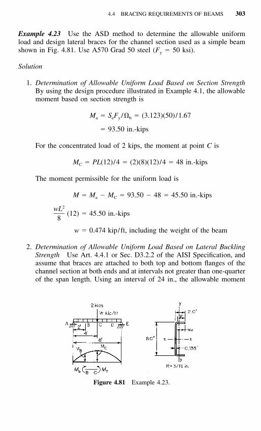
4.4 BRACING REQUIREMENTS OF BEAMS 303
Figure 4.81 Example 4.23.
Example 4.23 Use the ASD method to determine the allowable uniformload and design lateral braces for the channel section used as a simple beamshown in Fig. 4.81. Use A570 Grad 50 steel (Fy � 50 ksi).
Solution
1. Determination of Allowable Uniform Load Based on Section StrengthBy using the design procedure illustrated in Example 4.1, the allowablemoment based on section strength is
M � S F /� � (3.123)(50)/1.67a e y b
� 93.50 in.-kips
For the concentrated load of 2 kips, the moment at point C is
M � PL(12)/4 � (2)(8)(12)/4 � 48 in.-kipsC
The moment permissible for the uniform load is
M � M � M � 93.50 � 48 � 45.50 in.-kipsa C
2wL(12) � 45.50 in.-kips
8
w � 0.474 kip/ft, including the weight of the beam
2. Determination of Allowable Uniform Load Based on Lateral BucklingStrength Use Art. 4.4.1 or Sec. D3.2.2 of the AISI Specification, andassume that braces are attached to both top and bottom flanges of thechannel section at both ends and at intervals not greater than one-quarterof the span length. Using an interval of 24 in., the allowable moment

304 FLEXURAL MEMBERS
for portion BC (Fig. 4.81) on the basis of lateral buckling strength (Art.4.2.3.3) can be determined as follows: From Eq. (4.65),
C r Ab oF � �� �e ey tSf
where Cb �12.5Mmax
2.5M � 3M � 4M � 3Mmax 1 2 3
in which Mmax � 93.50 in.-kips, maximum moment at point CM1 � 69.11 in.-kips, at 1⁄4 point of unbraced lengthM2 � 78.66 in.-kips, at midpoint of unbraced lengthM3 � 86.79 in.-kips, at 3⁄4 point of unbraced length
Cb �12.5(93.50)
2.5(93.50) � 3(69.11) � 4(78.66) � 3(86.79)� 1.15
Based on Sec. C3.1.2.1 of the AISI Specification,
2 2 2r � �r � r � x � 3.09 in.o x y 0
Using the full cross-sectional area,
2A � 1.554 in.
From Eq. (4.68),
2 2� E � (29,500)� � � � 158.0 ksiey 2 2(K L /r ) (1 � 2 � 12/0.559)y y y
From Eq. (4.69),
21 � ECw� � GJ �� �t 2 2Ar (K L )o t t
21 � (29,500)(5.56)� (11,300)(0.00944) �� �2 2(1.554)(3.09) (1 � 2 � 12)
� 196.60 ksi
In the above equation, the values of J and Cw are computed from theDesign Manual or from Appendix B. Therefore, the elastic criticallateral–torsional buckling stress is
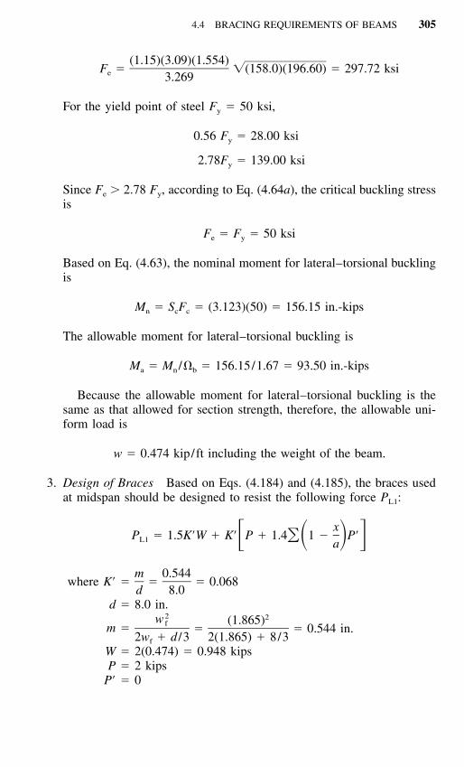
4.4 BRACING REQUIREMENTS OF BEAMS 305
(1.15)(3.09)(1.554)F � �(158.0)(196.60) � 297.72 ksie 3.269
For the yield point of steel Fy � 50 ksi,
0.56 F � 28.00 ksiy
2.78F � 139.00 ksiy
Since Fe � 2.78 Fy, according to Eq. (4.64a), the critical buckling stressis
F � F � 50 ksie y
Based on Eq. (4.63), the nominal moment for lateral–torsional bucklingis
M � S F � (3.123)(50) � 156.15 in.-kipsn c c
The allowable moment for lateral–torsional buckling is
M � M /� � 156.15/1.67 � 93.50 in.-kipsa n b
Because the allowable moment for lateral–torsional buckling is thesame as that allowed for section strength, therefore, the allowable uni-form load is
w � 0.474 kip/ft including the weight of the beam.
3. Design of Braces Based on Eqs. (4.184) and (4.185), the braces usedat midspan should be designed to resist the following force PL1:
xP � 1.5K�W � K� P � 1.4 1 � P��� � � �L1 a
where K� �m 0.544
� � 0.068d 8.0
d � 8.0 in.
m �2 2w (1.865)f
� � 0.544 in.2w � d /3 2(1.865) � 8/3f
W � 2(0.474) � 0.948 kipsP � 2 kips
P� � 0

306 FLEXURAL MEMBERS
PL1 � 1.5(0.068)(0.948) � 0.068(2) � 0.232 kips
The braces used at points (points B and D) should be designed to1–4resist the following force PL2:
P � 1.5K�W � 1.5(0.068)(0.948)L2
� 0.097 kips
4.4.1.2 Top Flange Connected to Sheathing Article 4.4.1.1 deals onlywith single-channel beams when neither flange is connected to deck or sheath-ing material. For C-sections designed according to section strength (Art. 4.2.2)and having deck or sheathing fastened directly to the top flanges in such amanner shown to effectively inhibit relative movement between the deck orsheathing and the purlin flange, provisions should be made according to Sec.D3.2.1 of the AISI Specification to restrain the flanges so that the maximumtop flange lateral displacements with respect to the purlin reaction points donot exceed the span length divided by 360. Section D3.2.1(a) of the Supple-ment to the 1996 edition of the AISI Specification states that for roof systemsusing C-sections for purlins with all compression flanges facing in the samedirection, a system possessing a restraint force, PL, in addition to resistingother loading, shall be provided as follows:
P � (0.05� cos� � sin�)WL
where W � total vertical load (nominal load for ASD, factored load forLRFD) supported by all purlin lines being restrained. When morethan one brace is used at a purlin line, the restraint force PL shallbe divided equally between all braces.
� � �1 for purlin facing upward direction, and� �1 for purlin facing downslope direction.
� � angle between the vertical and the plane of the web of theC-section, degrees.
The above equation was added in the Supplement in 1999 for calculating theanchorage forces for C-sections.1.333 A positive value for the force, PL, meansthat restraint is required to prevent movement of the purlin flange in theupward roof slope direction, and a negative value means that restraint is re-quired to prevent movement of purlin flange in the downward slope direction.If the top flanges of the adjacent lines of purlins face in opposite directions,a restraint system shall be provided to resist the down-slope component ofthe total gravity load.
Anchored braces may be connected to only one line of purlins in eachpurlin bay of each roof slope if provision is made to transmit forces fromother purlin lines through roof deck and its fastening system. Anchored braces
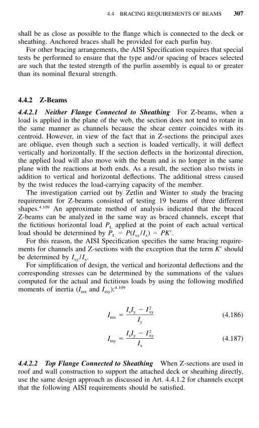
4.4 BRACING REQUIREMENTS OF BEAMS 307
shall be as close as possible to the flange which is connected to the deck orsheathing. Anchored braces shall be provided for each purlin bay.
For other bracing arrangements, the AISI Specification requires that specialtests be performed to ensure that the type and/or spacing of braces selectedare such that the tested strength of the purlin assembly is equal to or greaterthan its nominal flexural strength.
4.4.2 Z-Beams
4.4.2.1 Neither Flange Connected to Sheathing For Z-beams, when aload is applied in the plane of the web, the section does not tend to rotate inthe same manner as channels because the shear center coincides with itscentroid. However, in view of the fact that in Z-sections the principal axesare oblique, even though such a section is loaded vertically, it will deflectvertically and horizontally. If the section deflects in the horizontal direction,the applied load will also move with the beam and is no longer in the sameplane with the reactions at both ends. As a result, the section also twists inaddition to vertical and horizontal deflections. The additional stress causedby the twist reduces the load-carrying capacity of the member.
The investigation carried out by Zetlin and Winter to study the bracingrequirement for Z-beams consisted of testing 19 beams of three differentshapes.4.109 An approximate method of analysis indicated that the bracedZ-beams can be analyzed in the same way as braced channels, except thatthe fictitious horizontal load PL applied at the point of each actual verticalload should be determined by PL � P(Ixy /Ix) � PK�.
For this reason, the AISI Specification specifies the same bracing require-ments for channels and Z-sections with the exception that the term K� shouldbe determined by Ixy /Ix.
For simplification of design, the vertical and horizontal deflections and thecorresponding stresses can be determined by the summations of the valuescomputed for the actual and fictitious loads by using the following modifiedmoments of inertia (Imx and Imy):
4.109
2I I � Ix y xyI � (4.186)mx Iy
2I I � Ix y xyI � (4.187)my Ix
4.4.2.2 Top Flange Connected to Sheathing When Z-sections are used inroof and wall construction to support the attached deck or sheathing directly,use the same design approach as discussed in Art. 4.4.1.2 for channels exceptthat the following AISI requirements should be satisfied.

308 FLEXURAL MEMBERS
For roof systems having 4 to 20 Z-purlin lines with all top flanges facing in thedirection of the upward roof slope, and with restraint braces at the purlin sup-ports, midspan or one-third points, each brace shall be designed to resist a forcedetermined as follows (Ref. 1.333):
1. Single-Span System with Restraints at the Supports:
1.500.220bP � 0.5 cos� � sin� W (4.188)� �L 0.72 0.90 0.60n d tp
2. Single-Span System with Third-Point Restraints:
1.220.474bP � 0.5 cos� � sin� W (4.189)� �L 0.57 0.89 0.33n d tp
3. Single-Span System with Midspan Restraint:
1.320.224bP � cos� � sin� W (4.190)� �L 0.65 0.83 0.50n d tp
4. Multiple-Span System with Restraints at the Supports:
1.88 0.130.053b LP � C cos� � sin� W (4.191)� �L tr 0.95 1.07 0.94n d tp
with C � 0.63 for braces at end supports of multiple-span systemstr
C � 0.87 for braces at the first interior supportstr
C � 0.81 for all other bracestr
5. Multiple-Span Systems with Third-Point Restraints:
1.15 0.250.181b LP � C cos� � sin� W (4.192)� �L th 0.54 1.11 0.29n d tp
with C � 0.57 for outer braces in exterior spansth
C � 0.48 for all other bracesth
6. Multiple-Span System with Midspan Restraints:
1.32 0.180.116b LP � C cos� � sin� W (4.193)� �L ms 0.70 1.00 0.50n d tp
with Cms � 1.05 for braces in exterior spansCms � 0.90 for all other braces
where b � flange width, in.
4.4 BRACING REQUIREMENTS OF BEAMS 309
d � depth of section, in.t � thickness, in.
L � span length, in.� � angle between the vertical and the plane of the web of the
Z-section, degreesnp � number of parallel purlin linesW � total vertical load supported by the purlin lines between adjacent
supports, pounds
The force, PL, is positive when restraint is required to prevent movement of the purlinflanges in the upward roof slope direction.
For systems having less than four purlin lines, the brace force can be determined bytaking 1.1 times the force found from Eqs. (4.188) through (4.193), with np � 4. Forsystems having more than 20 purlin lines, the brace force can be determined from Eqs.(4.188) through (4.193), with np � 20.
Equations (4.188) through (4.193) were derived from a study conductedby Murray and Elhouar in 1985.4.110 These requirements are included in theAISI Specification since 1986 for the design of Z-purlins and girts. Becausethe original research was done assuming the roof was flat and the appliedloading was parallel to the purlin webs, the ‘‘cos�’’ term was added in 1999to compute the component of the vertical loading parallel to the purlin webs.
4.4.3 I-Beams
For I-beams, braces should be attached to top and bottom flanges at bothends. According to Eqs. (4.63) and (4.64), if Fe is greater than or equal to2.78Fy and Sc � Sf, no intermediate braces are required, except that additionalbraces should be placed at the locations of concentrated loads.
In case the value of Fe is less than 2.78Fy but greater than 0.56Fy, theintervals of braces should not exceed the required unbraced length determinedfrom Eqs. (4.63) and (4.64b). If Fe is less than or equal to 0.56Fy the requiredunbraced length should be determined from Eqs. (4.63) and (4.64c).
The design of braces is not specified in the AISI provisions. However, thebracing members may be designed for a capacity of 2% of the force resistedby the compression portion of the beam. This is a frequently used rule ofthumb but is a conservative approach, as proven by a rigorous analysis.
4.4.4 Continuous Lateral Bracing for Beams
When the compression flange of the cold-formed steel beam is closely con-nected to decking or sheathing material as to effectively restrain lateral de-flection of the flange and twisting of the member, previous studies made byWinter1.157,4.111 indicate that the required resistance to be provided by deckingmay be approximated as follows:
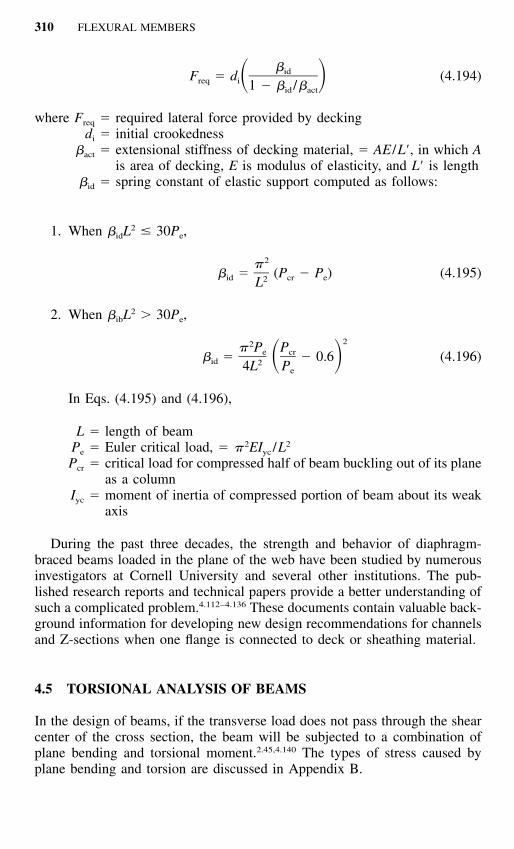
310 FLEXURAL MEMBERS
�idF � d (4.194)� �req i 1 � � /�id act
where Freq � required lateral force provided by deckingdi � initial crookedness
�act � extensional stiffness of decking material, � AE /L�, in which Ais area of decking, E is modulus of elasticity, and L� is length
�id � spring constant of elastic support computed as follows:
1. When �idL2 30Pe,
2�� � (P � P ) (4.195)id cr e2L
2. When �ibL2 � 30Pe,
22� P Pe cr� � � 0.6 (4.196)� �id 24L Pe
In Eqs. (4.195) and (4.196),
L � length of beamPe � Euler critical load, � �2EIyc /L2
Pcr � critical load for compressed half of beam buckling out of its planeas a column
Iyc � moment of inertia of compressed portion of beam about its weakaxis
During the past three decades, the strength and behavior of diaphragm-braced beams loaded in the plane of the web have been studied by numerousinvestigators at Cornell University and several other institutions. The pub-lished research reports and technical papers provide a better understanding ofsuch a complicated problem.4.112–4.136 These documents contain valuable back-ground information for developing new design recommendations for channelsand Z-sections when one flange is connected to deck or sheathing material.
4.5 TORSIONAL ANALYSIS OF BEAMS
In the design of beams, if the transverse load does not pass through the shearcenter of the cross section, the beam will be subjected to a combination ofplane bending and torsional moment.2.45,4.140 The types of stress caused byplane bending and torsion are discussed in Appendix B.

4.6 ADDITIONAL INFORMATION ON PURLINS 311
4.6 ADDITIONAL INFORMATION ON PURLINS
During the past two decades, the structural strength of cold-formed steel pur-lins has been investigated by a large number of researchers and engineers.For further information on this subject, the reader is referred to Refs. 4.137through 4.139, 4.141 through 4.155, and 4.187 through 4.191.