4 channel audio analog to digital converter - grassvalley.com · iqaad00 b15 iqaad00ops 30/03/07...
TRANSCRIPT
IQAAD00 B15
IQAAD00OPS 30/03/07 www.snellwilcox.com Version 1 Issue 1 B15.1
IQAAD00 4 Channel Audio Analog to Digital Converter
Table of Contents
Module Description ............................................. 2
Rear Panel Views................................................. 2
Block Diagram...................................................... 4
Features................................................................ 4
Technical Profile .................................................. 5
INPUTS.................................................................. 7
Analog Audio In ........................................... 7
OUTPUTS.............................................................. 7
AES Audio Out ............................................ 7
GPI (-1A only).............................................. 7
Ref(erence) Input (-1A only)........................ 8
25 Way D Type Connection Details ............ 9
CARD EDGE INDICATORS................................ 11
RollCall PC Control Panel Screens.................. 12
Analog Input .............................................. 12
Audio Input Delay ...................................... 13
Audio Mix 1, 2, 3 and 4.............................. 13
Audio Bus A and B/Audio Bus C and D .... 14
AES Out..................................................... 14
Audio Delay Setup..................................... 15
Audio Setup............................................... 16
Genlock ..................................................... 18
GPI ............................................................ 19
RollTrack ................................................... 21
Memories................................................... 23
Logging 1 and 2......................................... 24
ROLLCALL LOG FIELDS.......................... 25
Setup ......................................................... 26
Operation from an Active Control Panel ......... 28
RollTrack Audio Delay Tracking ...................... 31
Manual Revision Record ................................... 36

IQAAD00 B15
IQAAD00OPS 30/03/07 www.snellwilcox.com Version 1 Issue 1 B15.2
Module Description The IQAAD00 converts two analog stereo pairs, or four analog mono channels into two AES/EBU digital audio streams. Each analog input is sampled at 48 kHz with 20-bit resolution. Sampling can be free-running, locked to a reference video signal or 48KHz AES/EBU digital audio stream.
Video standard is automatically determined. The IQAAD00 also provides proc. amp control, channel routing and mixing, up to 0.5 s of tracking audio delay and additional fixed delay of up to 3 s adjustable in 1 ms steps.
Rear Panel Views IQAAD0015-1A
IQA
AD
0_**-1
A
AES OUT
1
2
AES & ANALOG AUDIO IN / OUT
IQAAD0014-1
IQA
AD
0_**-1
AES OUT
12
AES & ANALOG AUDIO IN / OUT
This manual covers the following products: IQAAD0015-1A Analog Audio ADC. 4 balanced analog audio inputs, 2 balanced and unbalanced AES/EBU outputs, 1 GPI
IQAAD0014-1 Analog Audio ADC. 4 balanced analog audio inputs, 2 balanced and unbalanced AES/EBU outputs
Product Comparison
Analog Inputs AES/EBU Outputs Product
Number Type Channel Type GPI
Reference Input
Width & Style
1 UNBAL 1
1 BAL
1 UNBAL IQAAD0015-1A 4 BAL
2 1 BAL
1 1 Single A
1 UNBAL 1
1 BAL IQAAD0014-1 4 BAL
2 1 UNBAL
1 BAL
No No Single O
IQAAD00 B15
IQAAD00OPS 30/03/07 www.snellwilcox.com Version 1 Issue 1 B15.3
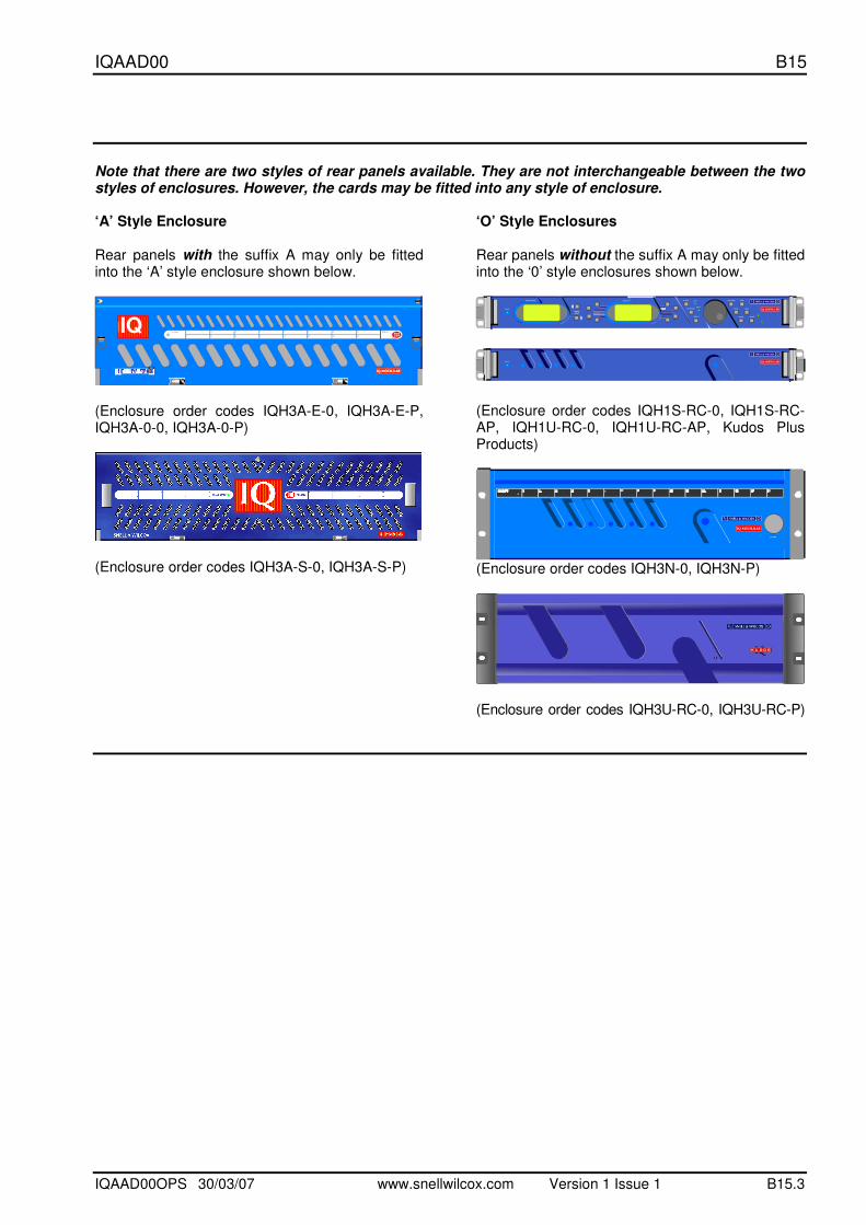
Note that there are two styles of rear panels available. They are not interchangeable between the two styles of enclosures. However, the cards may be fitted into any style of enclosure. ‘A’ Style Enclosure Rear panels with the suffix A may only be fitted into the ‘A’ style enclosure shown below.
IQ
(Enclosure order codes IQH3A-E-0, IQH3A-E-P, IQH3A-0-0, IQH3A-0-P)
(Enclosure order codes IQH3A-S-0, IQH3A-S-P)
‘O’ Style Enclosures Rear panels without the suffix A may only be fitted into the ‘0’ style enclosures shown below.
setup
lock save
recall
modules help
adjust
scroll
power previous
return
homecontrolinformation
display select
power
(Enclosure order codes IQH1S-RC-0, IQH1S-RC-AP, IQH1U-RC-0, IQH1U-RC-AP, Kudos Plus Products)
power
OPEN
(Enclosure order codes IQH3N-0, IQH3N-P)
(Enclosure order codes IQH3U-RC-0, IQH3U-RC-P)
IQAAD00 B15
IQAAD00OPS 30/03/07 www.snellwilcox.com Version 1 Issue 1 B15.4
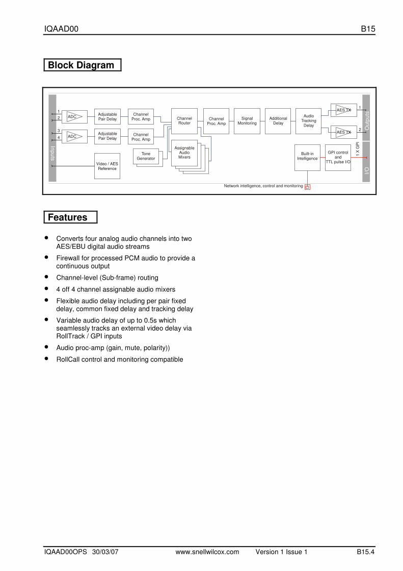
Block Diagram
Outp
uts
Inputs
I/O
GPI controland
TTL pulse I/O
Built-inIntelligence
Network control monitoring intelligence, and
ChannelRouter
Audio Tracking
Delay
AssignableAudio MixersTone
Generator
ToneGenerator
AdditionalDelay
Signal Monitoring
1 X
GP
I
1
2 ADC
4 ADC
3
AES TX
AES TX
1
2
Adjustable Pair Delay
Adjustable Pair Delay
ChannelProc. Amp
ChannelProc. Amp
ChannelProc. Amp
Outp
uts
Features
• Converts four analog audio channels into two AES/EBU digital audio streams
• Firewall for processed PCM audio to provide a continuous output
• Channel-level (Sub-frame) routing
• 4 off 4 channel assignable audio mixers
• Flexible audio delay including per pair fixed delay, common fixed delay and tracking delay
• Variable audio delay of up to 0.5s which seamlessly tracks an external video delay via RollTrack / GPI inputs
• Audio proc-amp (gain, mute, polarity))
• RollCall control and monitoring compatible
IQAAD00 B15
IQAAD00OPS 30/03/07 www.snellwilcox.com Version 1 Issue 1 B15.5
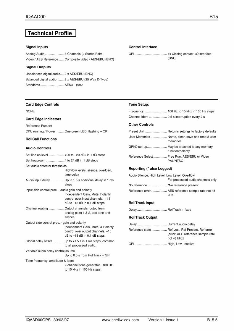
Technical Profile
Signal Inputs
Analog Audio ......................4 Channels (2 Stereo Pairs)
Video / AES Reference.......Composite video / AES/EBU (BNC)
Signal Outputs
Unbalanced digital audio.....2 x AES/EBU (BNC)
Balanced digital audio ........2 x AES/EBU (25 Way D-Type)
Standards...........................AES3 - 1992
Control Interface
GPI .................................... 1x Closing contact I/O interface
(BNC)
Card Edge Controls
NONE
Card Edge Indicators
Reference Present
CPU running / Power ..........One green LED, flashing = OK
RollCall Functions
Audio Controls
Set line up level ..................+20 to –20 dBu in 1 dB steps
Set headroom.....................4 to 24 dB in 1 dB steps
Set audio detector thresholds
High/low levels, silence, overload,
time delay
Audio input delay ................Up to 1.5 s additional delay in 1 ms
steps
Input side control proc. - audio gain and polarity
Independent Gain, Mute, Polarity
control over input channels. +18
dB to –18 dB in 0.1 dB steps.
Channel routing .................Output channels routed from
analog pairs 1 & 2, test tone and
silence
Output side control proc. - gain and polarity
Independent Gain, Mute, & Polarity
control over output channels. +18
dB to –18 dB in 0.1 dB steps.
Global delay offset..............up to +1.5 s in 1 ms steps, common
to all processed audio.
Variable audio delay control source
Up to 0.5 s from RollTrack + GPI
Tone frequency, amplitude & Ident
2-channel tone generator. 100 Hz
to 15 kHz in 100 Hz steps.
Tone Setup:
Frequency.......................... 100 Hz to 15 kHz in 100 Hz steps
Channel Ident .................... 0.5 s interruption every 2 s
Other Controls
Preset Unit......................... Returns settings to factory defaults
User Memories .................. Name, clear, save and read 8 user
memories
GPI/O set-up...................... May be attached to any memory
function/polarity
Reference Select ............... Free Run, AES/EBU or Video
PAL/NTSC
Reporting (* also Logged)
Audio Silence, High Level, Low Level, Overflow
For processed audio channels only
No reference...................... *No reference present
Reference error.................. AES reference sample rate not 48
kHz
RollTrack Input
Delay ................................. RollTrack + fixed
RollTrack Output
Delay ................................. Current audio delay
Reference state ................. Ref Lost, Ref Present, Ref error
[error: AES reference sample rate
not 48 kHz]
GPI .................................... High, Low, Inactive

IQAAD00 B15
IQAAD00OPS 30/03/07 www.snellwilcox.com Version 1 Issue 1 B15.6
Technical Profile (continued)
Specifications
Analog Audio Input (Balanced)
Analog Input Impedance.....10 k ohms
Frequency Response..........20 Hz to 20 kHz (±0.1 dB)
Distortion (THD+N) .............Better than -95 dB, 1kHz@ -
1 dBFS
Dynamic range ...................> 106 dB
Max input level....................+24 dBu
Digital Audio Output (Balanced)
Connector/Format...............25 W D
Level...................................3 V p-p typical into 110 Ohms
Digital Audio Output (Unbalanced)
Connector/Format...............BNC
Level...................................1 V p-p typical into 75 Ohms
Reference
Reference Return Loss ...... Better than -35 dB to 5.8 MHz
Reference Input Level........ 1 V p-p ± 3 dB
Analog Reference Input Standard
48 kHz AES/EBU, 625/525 line
Power Consumption
Module Power Consumption
6 W max.
IQAAD00 B15
IQAAD00OPS 30/03/07 www.snellwilcox.com Version 1 Issue 1 B15.7
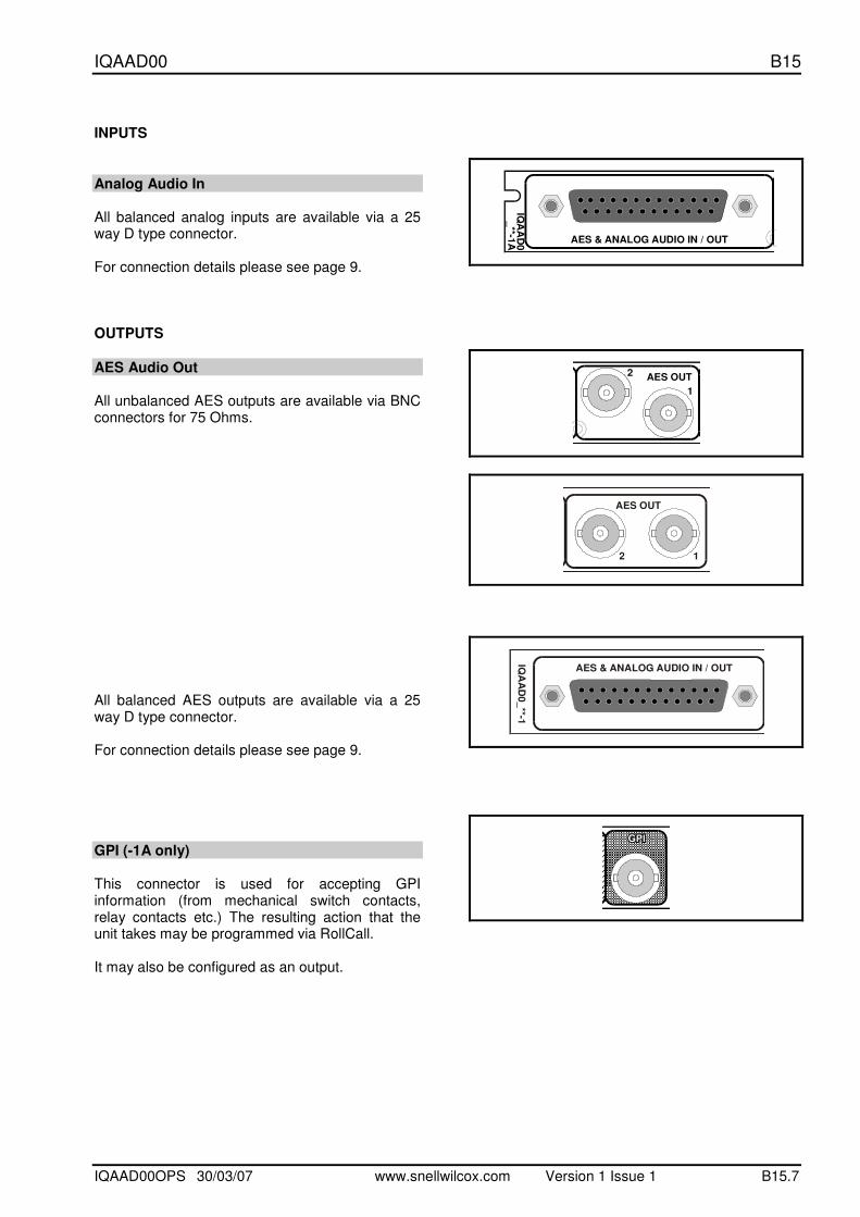
INPUTS
Analog Audio In All balanced analog inputs are available via a 25 way D type connector. For connection details please see page 9. OUTPUTS
AES Audio Out All unbalanced AES outputs are available via BNC connectors for 75 Ohms. All balanced AES outputs are available via a 25 way D type connector. For connection details please see page 9.
GPI (-1A only) This connector is used for accepting GPI information (from mechanical switch contacts, relay contacts etc.) The resulting action that the unit takes may be programmed via RollCall. It may also be configured as an output.
IQA
AD
0_**-1
A AES & ANALOG AUDIO IN / OUT
AES OUT
1
2
AES OUT
12
IQA
AD
0_**-1
AES & ANALOG AUDIO IN / OUT
IQAAD00 B15
IQAAD00OPS 30/03/07 www.snellwilcox.com Version 1 Issue 1 B15.8
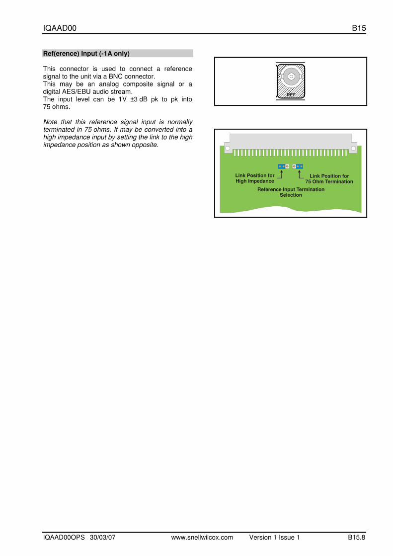
Ref(erence) Input (-1A only) This connector is used to connect a reference signal to the unit via a BNC connector. This may be an analog composite signal or a digital AES/EBU audio stream. The input level can be 1V ±3 dB pk to pk into 75 ohms. Note that this reference signal input is normally terminated in 75 ohms. It may be converted into a high impedance input by setting the link to the high impedance position as shown opposite.
AES OUT
Reference Input TerminationSelection
Link Position for High Impedance
Link Position for 75 Ohm Termination

IQAAD00 B15
IQAAD00OPS 30/03/07 www.snellwilcox.com Version 1 Issue 1 B15.9
25 Way D Type Connection Details By Pin Number
Pin No Description Connection
1 Chassis Ground Ground
2 Channel 1 + Do not use
3 Channel 2 + Do not use
4 Ground (2) Ground
5 Channel 1 + Analog Input 1 +
6 Channel 2 + Analog Input 2 +
7 Ground (2) Analog Input 2 Ground
8 Channel 3 + Analog Input 3 +
9 Channel 4 + Analog Input 4 +
10 Ground (4) Analog Input 4 Ground
11 Channel 7 + AES Audio Output 2 +
12 Channel 8 + AES Audio Output 1 +
13 Ground (8) Ground
14 Ground (1) Ground
15 Channel 1 – Do not use
16 Channel 2 – Do not use
17 Ground (1) Analog Input 1 Ground
18 Channel 1 – Analog Input 1 –
19 Channel 2 – Analog Input 2 –
20 Ground (3) Analog Input 3 Ground
21 Channel 3 – Analog Input 3 –
22 Channel 4 – Analog Input 4 –
23 Ground (7) Ground
24 Channel 7 – AES Audio Output 2 –
25 Channel 8 – AES Audio Output 1 –
By Function
Pin No Description Connection
1 Chassis Ground Ground
2 Channel 1 + Do not use
15 Channel 1 – Do not use
14 Ground (1) Ground
3 Channel 2 + Do not use
16 Channel 2 – Do not use
4 Ground (2) Ground
5 Channel 1 + Analog Input 1 +
18 Channel 1 – Analog Input 1 –
17 Ground (1) Analog Input 1 Ground
6 Channel 2 + Analog Input 2 +
19 Channel 2 – Analog Input 2 –
7 Ground (2) Analog Input 2 Ground
8 Channel 3 + Analog Input 3 +
21 Channel 3 – Analog Input 3 –
20 Ground (3) Analog Input 3 Ground
9 Channel 4 + Analog Input 4 +
22 Channel 4 – Analog Input 4 –
10 Ground (4) Analog Input 4 Ground
11 Channel 7 + AES Audio Output 2 +
24 Channel 7 – AES Audio Output 2 –
23 Ground (7) Ground
12 Channel 8 + AES Audio Output 1 +
25 Channel 8 – AES Audio Output 1 –
13 Ground (8) Ground
IQAAD00 B15
IQAAD00OPS 30/03/07 www.snellwilcox.com Version 1 Issue 1 B15.10
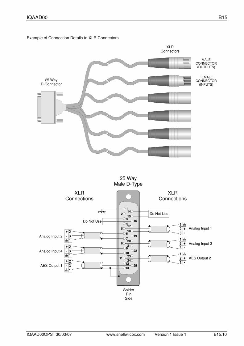
Example of Connection Details to XLR Connectors
25 WayD-Connector
XLRConnectors
MALE CONNECTOR(OUTPUTS)
FEMALE CONNECTOR
(INPUTS)
25 WayMale D-Type
XLRConnections
SolderPinSide
16
19
22
25
2
5
8
11
1
3
4
6
7
9
10
12
13
14
15
17
18
20
21
23
24
XLRConnections
AES Output 1
Analog Input 4
Analog Input 2
Analog Input 1
Analog Input 3
AES Output 2
Do Not Use
Do Not Use
IQAAD00 B15
IQAAD00OPS 30/03/07 www.snellwilcox.com Version 1 Issue 1 B15.11
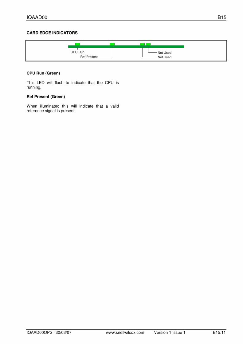
CARD EDGE INDICATORS
CPU Run Not Used
Not UsedRef Present
CPU Run (Green) This LED will flash to indicate that the CPU is running. Ref Present (Green) When illuminated this will indicate that a valid reference signal is present.
IQAAD00 B15
IQAAD00OPS 30/03/07 www.snellwilcox.com Version 1 Issue 1 B15.12
RollCall PC Control Panel Screens
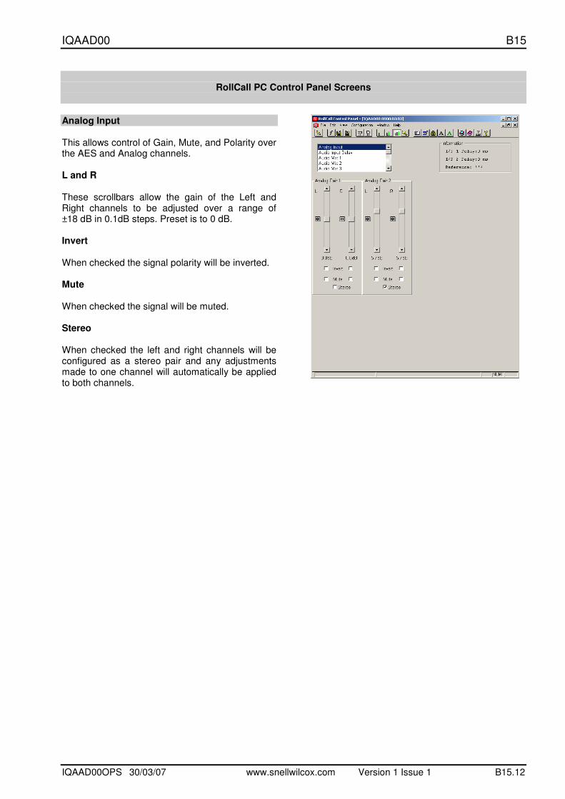
Analog Input This allows control of Gain, Mute, and Polarity over the AES and Analog channels. L and R These scrollbars allow the gain of the Left and Right channels to be adjusted over a range of ±18 dB in 0.1dB steps. Preset is to 0 dB. Invert When checked the signal polarity will be inverted. Mute When checked the signal will be muted. Stereo When checked the left and right channels will be configured as a stereo pair and any adjustments made to one channel will automatically be applied to both channels.
IQAAD00 B15
IQAAD00OPS 30/03/07 www.snellwilcox.com Version 1 Issue 1 B15.13
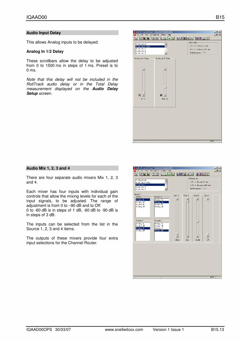
Audio Input Delay This allows Analog inputs to be delayed. Analog In 1/2 Delay These scrollbars allow the delay to be adjusted from 0 to 1500 ms in steps of 1 ms. Preset is to 0 ms. Note that this delay will not be included in the RollTrack audio delay or in the Total Delay measurement displayed on the Audio Delay Setup screen.
Audio Mix 1, 2, 3 and 4 There are four separate audio mixers Mix 1, 2, 3 and 4. Each mixer has four inputs with individual gain controls that allow the mixing levels for each of the input signals, to be adjusted. The range of adjustment is from 0 to –90 dB and to Off. 0 to -60 dB is in steps of 1 dB, -60 dB to -90 dB is in steps of 3 dB. The inputs can be selected from the list in the Source 1, 2, 3 and 4 items. The outputs of these mixers provide four extra input selections for the Channel Router.

IQAAD00 B15
IQAAD00OPS 30/03/07 www.snellwilcox.com Version 1 Issue 1 B15.14
Audio Bus A and B/Audio Bus C and D This function allows the inputs for the four audio buses of the router to be selected. For each bus any source may be selected from the list for the left and right channels. L and R These scrollbars allow the gain to be adjusted over a range of ±18 dB in 0.1dB steps. Preset is to 0 dB. Invert When checked the signal polarity will be inverted. Mute When checked the signal will be muted. Stereo When checked the left and right channels will be configured as a stereo pair and any adjustments made to one channel will automatically be applied to both channels.
AES Out This allows the signal source for the AES output to be selected from the list of items for the two AES sources. Silence and audio test tones may also be selected.
IQAAD00 B15
IQAAD00OPS 30/03/07 www.snellwilcox.com Version 1 Issue 1 B15.15
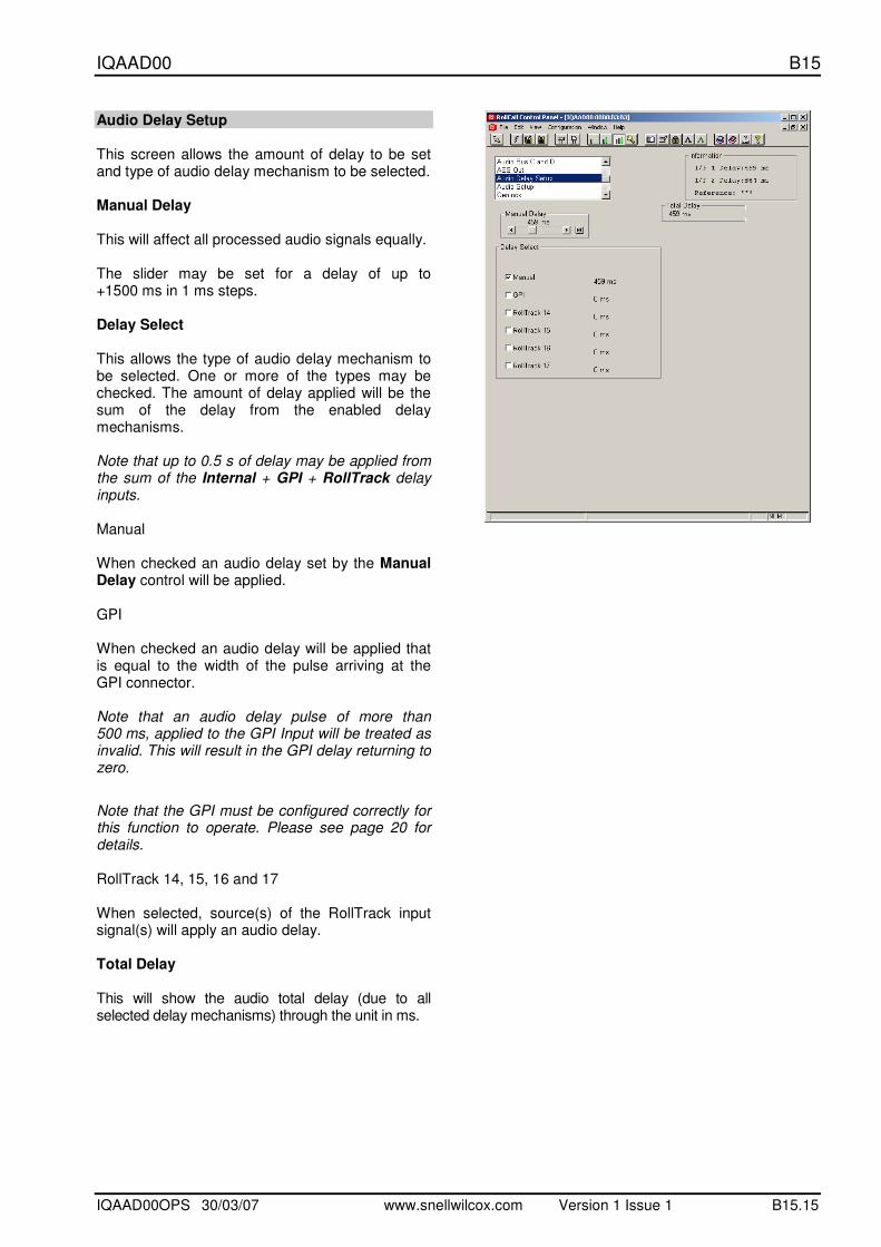
Audio Delay Setup This screen allows the amount of delay to be set and type of audio delay mechanism to be selected. Manual Delay This will affect all processed audio signals equally. The slider may be set for a delay of up to +1500 ms in 1 ms steps. Delay Select This allows the type of audio delay mechanism to be selected. One or more of the types may be checked. The amount of delay applied will be the sum of the delay from the enabled delay mechanisms. Note that up to 0.5 s of delay may be applied from the sum of the Internal + GPI + RollTrack delay inputs. Manual When checked an audio delay set by the Manual Delay control will be applied. GPI When checked an audio delay will be applied that is equal to the width of the pulse arriving at the GPI connector. Note that an audio delay pulse of more than 500 ms, applied to the GPI Input will be treated as invalid. This will result in the GPI delay returning to zero.
Note that the GPI must be configured correctly for this function to operate. Please see page 20 for details. RollTrack 14, 15, 16 and 17 When selected, source(s) of the RollTrack input signal(s) will apply an audio delay. Total Delay This will show the audio total delay (due to all selected delay mechanisms) through the unit in ms.

IQAAD00 B15
IQAAD00OPS 30/03/07 www.snellwilcox.com Version 1 Issue 1 B15.16
Audio Setup Audio Monitoring The four audio buses are monitored and level detectors provide status information and logging data. Silence The level at which the signal is considered to have dropped to silence may be set with this control. The range is from -80 dB to 0 dB in steps of 1 dB. Preset is to -70 dB. Low Level The level at which the signal is considered to have dropped to a Low Level may be set with this control. The range is from -80 dB to 0 dB in steps of 1 dB. Preset is to -60 dB. High Level The level at which the signal is considered to have risen to a High Level may be set with this control. The range is from -80 dB to 0 dB in steps of 1 dB. Preset is to -10 dB. Overload The level at which the signal is considered to have risen to an Overload condition may be set with this control. The range is from -80 dB to 0 dB in steps of 1 dB. Preset is to 0 dB. Warning Timer All the above monitoring facilities will only operate after a time interval set by this control. A valid signal is reported immediately. The range is from 1 to 20 seconds. Preset is to 10 seconds. Audio Tone The frequency of the Audio Test Tone may be set using this control. Left and right channels may be set independently. Frequency L and R The range is from 100 Hz to 15 kHz in steps of 100 Hz. Preset is to 400 Hz.
IQAAD00 B15
IQAAD00OPS 30/03/07 www.snellwilcox.com Version 1 Issue 1 B15.17
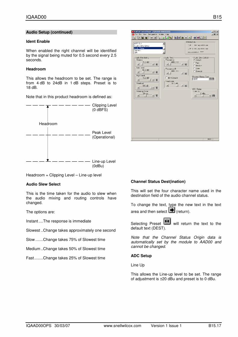
Audio Setup (continued) Ident Enable When enabled the right channel will be identified by the signal being muted for 0.5 second every 2.5 seconds. Headroom This allows the headroom to be set. The range is from 4 dB to 24dB in 1 dB steps. Preset is to 18 dB. Note that in this product headroom is defined as:
Clipping Level(0 dBFS)
Peak Level(Operational)
Line-up Level(0dBu)
Headroom
Headroom = Clipping Level – Line-up level Audio Slew Select This is the time taken for the audio to slew when the audio mixing and routing controls have changed. The options are: Instant ....The response is immediate Slowest ..Change takes approximately one second Slow .......Change takes 75% of Slowest time Medium ..Change takes 50% of Slowest time Fast........Change takes 25% of Slowest time
Channel Status Dest(ination) This will set the four character name used in the destination field of the audio channel status. To change the text, type the new text in the text
area and then select (return).
Selecting Preset will return the text to the default text (DEST). Note that the Channel Status Origin data is automatically set by the module to AAD00 and cannot be changed. ADC Setup Line Up This allows the Line-up level to be set. The range of adjustment is ±20 dBu and preset is to 0 dBu.
IQAAD00 B15
IQAAD00OPS 30/03/07 www.snellwilcox.com Version 1 Issue 1 B15.18
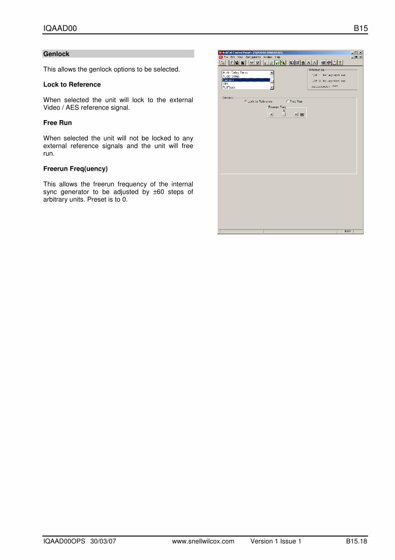
Genlock This allows the genlock options to be selected. Lock to Reference When selected the unit will lock to the external Video / AES reference signal. Free Run When selected the unit will not be locked to any external reference signals and the unit will free run. Freerun Freq(uency) This allows the freerun frequency of the internal sync generator to be adjusted by ±60 steps of arbitrary units. Preset is to 0.
IQAAD00 B15
IQAAD00OPS 30/03/07 www.snellwilcox.com Version 1 Issue 1 B15.19
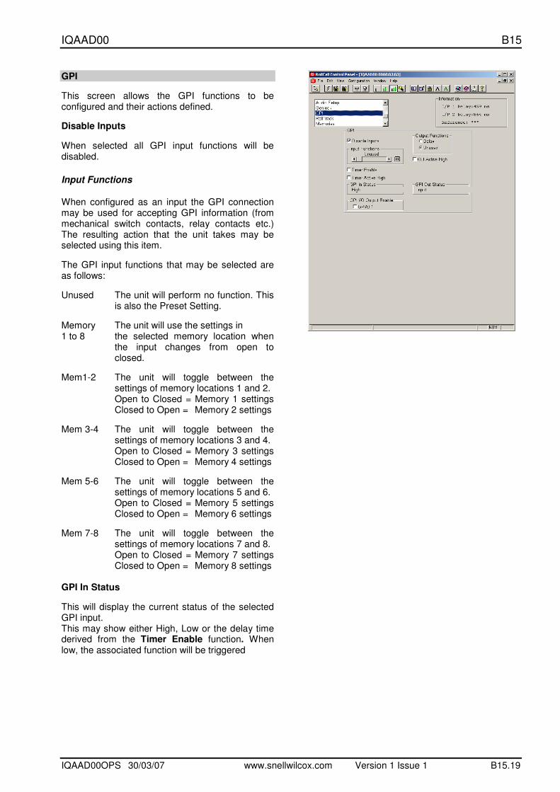
GPI
This screen allows the GPI functions to be configured and their actions defined.
Disable Inputs
When selected all GPI input functions will be disabled.
Input Functions
When configured as an input the GPI connection may be used for accepting GPI information (from mechanical switch contacts, relay contacts etc.) The resulting action that the unit takes may be selected using this item.
The GPI input functions that may be selected are as follows:
Unused The unit will perform no function. This is also the Preset Setting.
Memory The unit will use the settings in 1 to 8 the selected memory location when
the input changes from open to closed.
Mem1-2 The unit will toggle between the settings of memory locations 1 and 2.
Open to Closed = Memory 1 settings Closed to Open = Memory 2 settings
Mem 3-4 The unit will toggle between the settings of memory locations 3 and 4.
Open to Closed = Memory 3 settings Closed to Open = Memory 4 settings
Mem 5-6 The unit will toggle between the settings of memory locations 5 and 6.
Open to Closed = Memory 5 settings Closed to Open = Memory 6 settings
Mem 7-8 The unit will toggle between the settings of memory locations 7 and 8.
Open to Closed = Memory 7 settings Closed to Open = Memory 8 settings
GPI In Status
This will display the current status of the selected GPI input. This may show either High, Low or the delay time derived from the Timer Enable function. When low, the associated function will be triggered
IQAAD00 B15
IQAAD00OPS 30/03/07 www.snellwilcox.com Version 1 Issue 1 B15.20
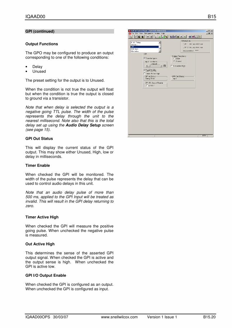
GPI (continued)
Output Functions The GPO may be configured to produce an output corresponding to one of the following conditions:
• Delay
• Unused The preset setting for the output is to Unused. When the condition is not true the output will float but when the condition is true the output is closed to ground via a transistor. Note that when delay is selected the output is a negative going TTL pulse. The width of the pulse represents the delay through the unit to the nearest millisecond. Note also that this is the total delay set up using the Audio Delay Setup screen (see page 15). GPI Out Status This will display the current status of the GPI output. This may show either Unused, High, low or delay in milliseconds. Timer Enable When checked the GPI will be monitored. The width of the pulse represents the delay that can be used to control audio delays in this unit. Note that an audio delay pulse of more than 500 ms, applied to the GPI Input will be treated as invalid. This will result in the GPI delay returning to zero.
Timer Active High When checked the GPI will measure the positive going pulse. When unchecked the negative pulse is measured. Out Active High This determines the sense of the asserted GPI output signal. When checked the GPI is active and the output sense is high. When unchecked the GPI is active low. GPI I/O Output Enable When checked the GPI is configured as an output. When unchecked the GPI is configured as input.

IQAAD00 B15
IQAAD00OPS 30/03/07 www.snellwilcox.com Version 1 Issue 1 B15.21
RollTrack This function allows information to be sent, via the RollCall™ network, to other compatible units connected on the same network. For example, it can enable compatible audio delay units to produce an audio delay dependent on this and other similar units. The audio delay unit will dynamically follow or track the received delay-time information. This allows processed video signals to be timed correctly with audio signals. This automatic tracking system via the RollCall™ network is call RollTrack.
For more detailed information, see the RollTrack section (Appendix) at the end of this manual.
RollTrack Index
This item allows up to 70 destinations to be selected. RollTrack Source This allows the source of information that triggers the transmission of data to be selected. The options are:
Unused (off)
Audio Delay
Ref Lost
Ref Present
Ref Error
GPI Low
GPI High
GPI Inactive
The destination for the information is set by the network code address as follows:
Network Address
This item allows the address of the selected destination unit to be set. To change the address, type the new destination
in the text area and then select (return).
(Preset) returns to the default destination The full RollTrack address has four sets of numbers For example: 0000:10:01*99 The first set (0000) is the network segment code number The second set (10) is the number identifying the (enclosure/mainframe) unit. The third set (01) is the slot number in the unit The Fourth Set (99) Each RollCall unit has a unique identification embedded in the units’ software. In this example 99 represents an IQBAXR, 142 would represent an IQDAMDD, 255 a TBS100D etc. Inserting this number in the RollTrack address ensures that only the correct type of unit (in this example an IQBAXR) will respond to the RollTrack command; any other unit will ignore the command. If this number was set to 00 any type of unit at this location would respond to the RollTrack command, possibly causing unpredictable results.

IQAAD00 B15
IQAAD00OPS 30/03/07 www.snellwilcox.com Version 1 Issue 1 B15.22
RollTrack (continued) RollTrack Command The full RollTrack command has two sets of numbers For example: 84*156 The first set (84) is the RollTrack command number Note that only command numbers 14,15,16 and 17 should be used for audio delay The second set (156) is the value sent with the RollTrack command number Note that when video delay is selected as the RollTrack source the value sent with the RollTrack command is the video delay value not the value set. For details of the RollCall command values for specific units please contact your local Snell & Wilcox agent. Disable All When this item is checked all RollTrack items will be disabled. Note: To avoid incorrect RollTrack information being generated, it is advisable to select this control while setting up RollTrack functions. RollTrack Sending This item shows when the unit is actively sending the RollTrack command. This may show: String A string value is always being sent. Number A number value is always being sent. No The message is not being sent. Yes The message is being sent. Internal Inconsistent behavior; please contact Type Error your local Snell & Wilcox agent.
RollTrack Status This item will show the status of the currently selected RollTrack index. This may show: OK RollTrack message sent and received
OK. Unknown Rolltrack message has been sent but
it has not yet completed. Timeout RollTrack message sent but
acknowledgement not received. This could be because the destination unit is not at the location specified.
Error This indicates a broken RollCall state. Bad This indicates a broken RollCall packet.
IQAAD00 B15
IQAAD00OPS 30/03/07 www.snellwilcox.com Version 1 Issue 1 B15.23
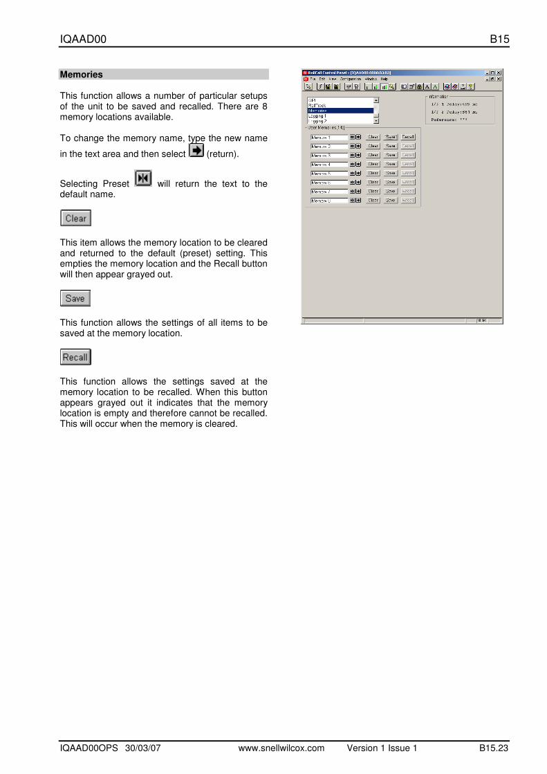
Memories This function allows a number of particular setups of the unit to be saved and recalled. There are 8 memory locations available. To change the memory name, type the new name
in the text area and then select (return).
Selecting Preset will return the text to the default name.
This item allows the memory location to be cleared and returned to the default (preset) setting. This empties the memory location and the Recall button will then appear grayed out.
This function allows the settings of all items to be saved at the memory location.
This function allows the settings saved at the memory location to be recalled. When this button appears grayed out it indicates that the memory location is empty and therefore cannot be recalled. This will occur when the memory is cleared.

IQAAD00 B15
IQAAD00OPS 30/03/07 www.snellwilcox.com Version 1 Issue 1 B15.24
Logging 1 and 2 Information about various parameters can be made available to a logging device that is attached to the RollCall™ network by checking the appropriate box. The status is shown to the right of the item. Any of the items may be selected from the list.
IQAAD00 B15
IQAAD00OPS 30/03/07 www.snellwilcox.com Version 1 Issue 1 B15.25
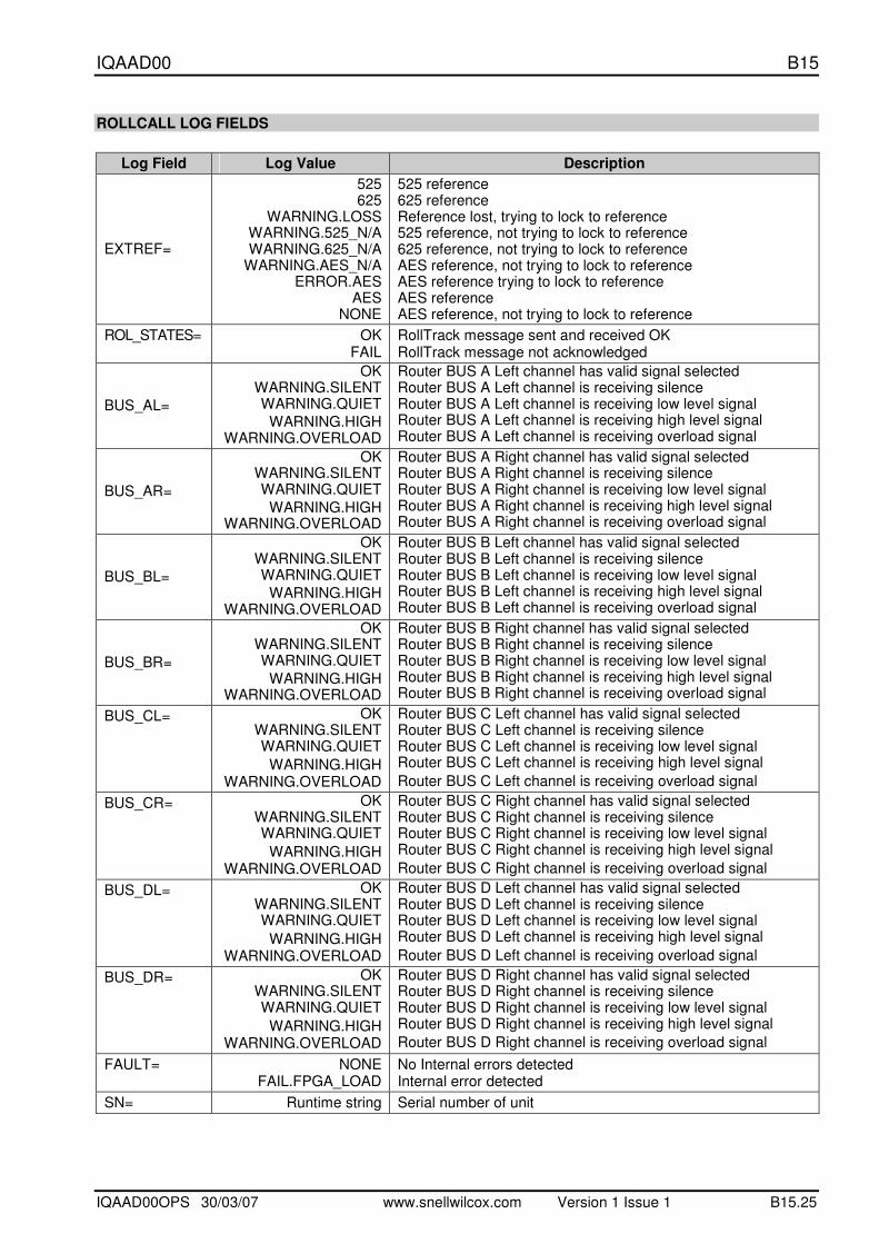
ROLLCALL LOG FIELDS
Log Field Log Value Description
EXTREF=
525 625
WARNING.LOSS WARNING.525_N/A WARNING.625_N/A
WARNING.AES_N/A ERROR.AES
AES NONE
525 reference 625 reference Reference lost, trying to lock to reference 525 reference, not trying to lock to reference 625 reference, not trying to lock to reference AES reference, not trying to lock to reference AES reference trying to lock to reference AES reference AES reference, not trying to lock to reference
ROL_STATES= OK FAIL
RollTrack message sent and received OK RollTrack message not acknowledged
BUS_AL=
OK WARNING.SILENT WARNING.QUIET
WARNING.HIGH WARNING.OVERLOAD
Router BUS A Left channel has valid signal selected Router BUS A Left channel is receiving silence Router BUS A Left channel is receiving low level signal Router BUS A Left channel is receiving high level signal Router BUS A Left channel is receiving overload signal
BUS_AR=
OK WARNING.SILENT WARNING.QUIET
WARNING.HIGH WARNING.OVERLOAD
Router BUS A Right channel has valid signal selected Router BUS A Right channel is receiving silence Router BUS A Right channel is receiving low level signal Router BUS A Right channel is receiving high level signal Router BUS A Right channel is receiving overload signal
BUS_BL=
OK WARNING.SILENT WARNING.QUIET
WARNING.HIGH WARNING.OVERLOAD
Router BUS B Left channel has valid signal selected Router BUS B Left channel is receiving silence Router BUS B Left channel is receiving low level signal Router BUS B Left channel is receiving high level signal Router BUS B Left channel is receiving overload signal
BUS_BR=
OK WARNING.SILENT WARNING.QUIET
WARNING.HIGH WARNING.OVERLOAD
Router BUS B Right channel has valid signal selected Router BUS B Right channel is receiving silence Router BUS B Right channel is receiving low level signal Router BUS B Right channel is receiving high level signal Router BUS B Right channel is receiving overload signal
BUS_CL= OK WARNING.SILENT WARNING.QUIET
WARNING.HIGH WARNING.OVERLOAD
Router BUS C Left channel has valid signal selected Router BUS C Left channel is receiving silence Router BUS C Left channel is receiving low level signal Router BUS C Left channel is receiving high level signal
Router BUS C Left channel is receiving overload signal
BUS_CR= OK WARNING.SILENT WARNING.QUIET
WARNING.HIGH WARNING.OVERLOAD
Router BUS C Right channel has valid signal selected Router BUS C Right channel is receiving silence Router BUS C Right channel is receiving low level signal Router BUS C Right channel is receiving high level signal
Router BUS C Right channel is receiving overload signal
BUS_DL= OK WARNING.SILENT WARNING.QUIET
WARNING.HIGH WARNING.OVERLOAD
Router BUS D Left channel has valid signal selected Router BUS D Left channel is receiving silence Router BUS D Left channel is receiving low level signal Router BUS D Left channel is receiving high level signal
Router BUS D Left channel is receiving overload signal
BUS_DR= OK WARNING.SILENT WARNING.QUIET
WARNING.HIGH WARNING.OVERLOAD
Router BUS D Right channel has valid signal selected Router BUS D Right channel is receiving silence Router BUS D Right channel is receiving low level signal Router BUS D Right channel is receiving high level signal
Router BUS D Right channel is receiving overload signal
FAULT= NONE FAIL.FPGA_LOAD
No Internal errors detected Internal error detected
SN= Runtime string Serial number of unit
IQAAD00 B15
IQAAD00OPS 30/03/07 www.snellwilcox.com Version 1 Issue 1 B15.26
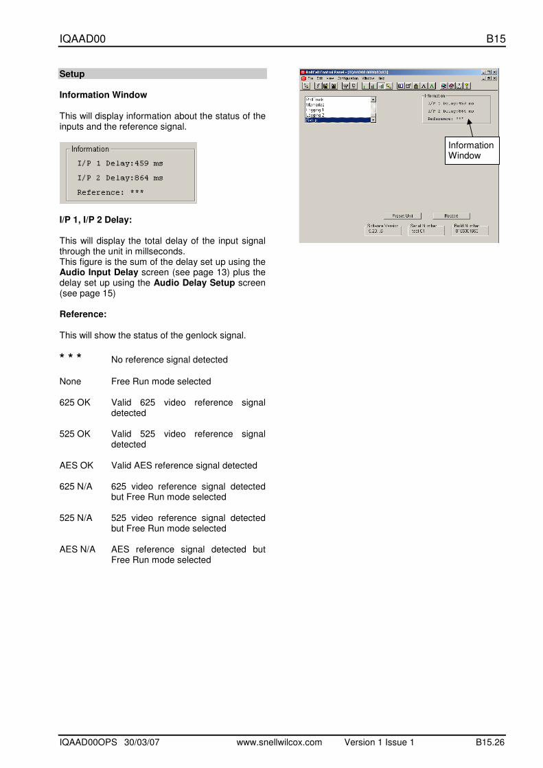
Setup Information Window This will display information about the status of the inputs and the reference signal.
I/P 1, I/P 2 Delay: This will display the total delay of the input signal through the unit in millseconds. This figure is the sum of the delay set up using the Audio Input Delay screen (see page 13) plus the delay set up using the Audio Delay Setup screen (see page 15) Reference: This will show the status of the genlock signal.
* * * No reference signal detected
None Free Run mode selected 625 OK Valid 625 video reference signal
detected 525 OK Valid 525 video reference signal
detected AES OK Valid AES reference signal detected 625 N/A 625 video reference signal detected
but Free Run mode selected 525 N/A 525 video reference signal detected
but Free Run mode selected AES N/A AES reference signal detected but
Free Run mode selected
Information Window

IQAAD00 B15
IQAAD00OPS 30/03/07 www.snellwilcox.com Version 1 Issue 1 B15.27
Setup (continued)
Selecting this item sets all adjustment functions that include a preset facility, to their preset values. Note that this is a momentary action.
This will reboot the unit simulating a power-down power-up cycle restoring power-up settings. Software version This item shows the version of the software fitted in the module. Serial Number This item shows the serial number of the module Build Number This will indicate the factory build number. This number defines all parameters of the unit (software versions, build level etc.) for identification purposes.
Information Window
IQAAD00 B15
IQAAD00OPS 30/03/07 www.snellwilcox.com Version 1 Issue 1 B15.28
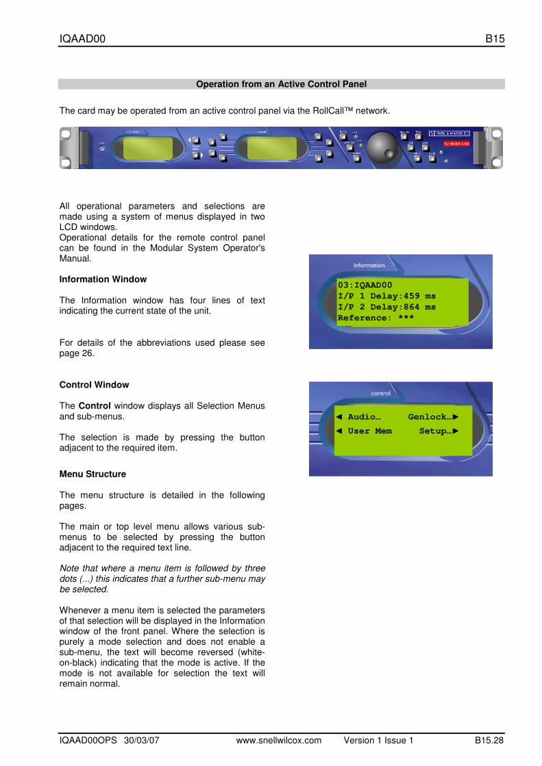
Operation from an Active Control Panel
The card may be operated from an active control panel via the RollCall™ network.
All operational parameters and selections are made using a system of menus displayed in two LCD windows. Operational details for the remote control panel can be found in the Modular System Operator's Manual. Information Window The Information window has four lines of text indicating the current state of the unit.
For details of the abbreviations used please see page 26.
Control Window The Control window displays all Selection Menus and sub-menus. The selection is made by pressing the button adjacent to the required item.
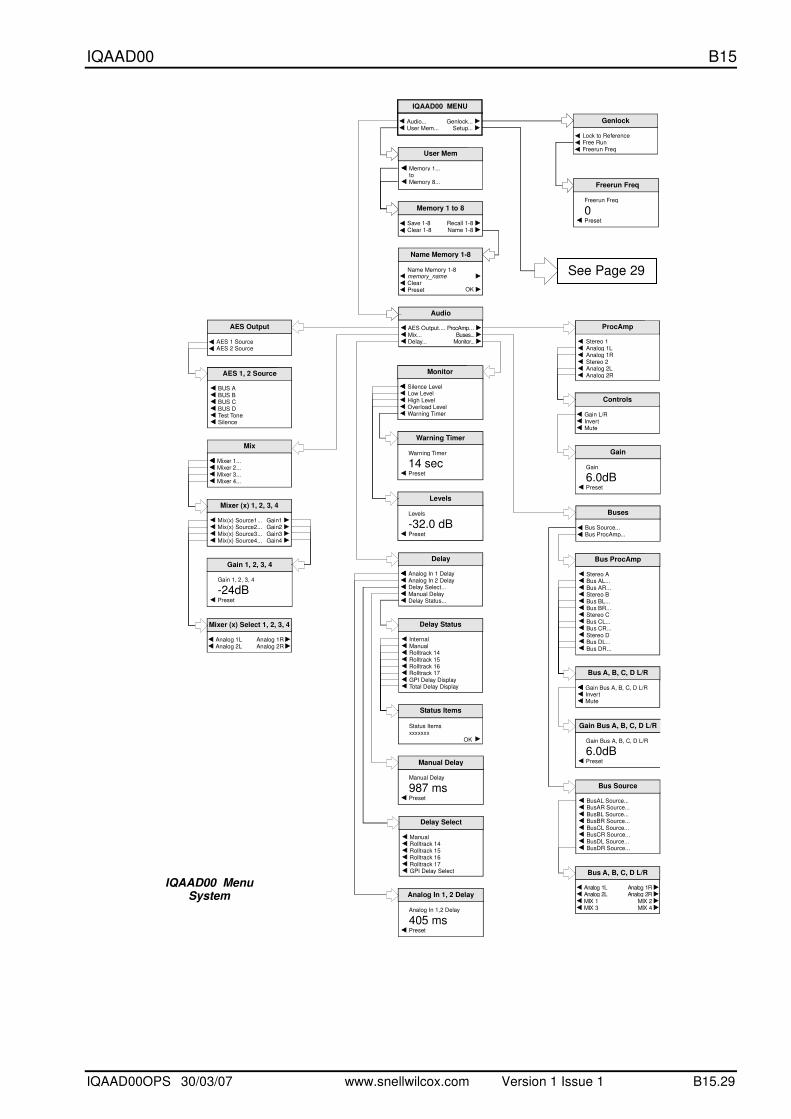
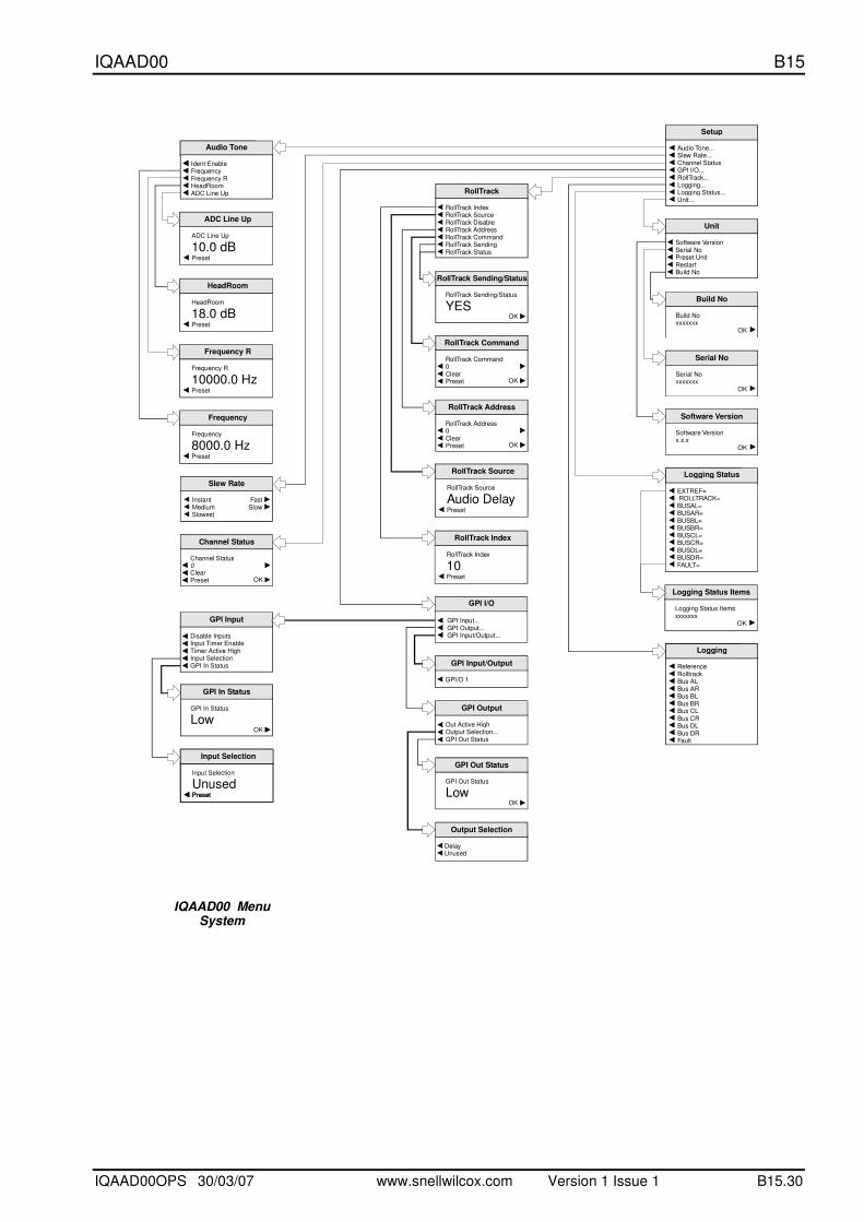
Menu Structure The menu structure is detailed in the following pages. The main or top level menu allows various sub-menus to be selected by pressing the button adjacent to the required text line. Note that where a menu item is followed by three dots (...) this indicates that a further sub-menu may be selected. Whenever a menu item is selected the parameters of that selection will be displayed in the Information window of the front panel. Where the selection is purely a mode selection and does not enable a sub-menu, the text will become reversed (white-on-black) indicating that the mode is active. If the mode is not available for selection the text will remain normal.
03:IQAAD00
I/P 1 Delay:459 ms
I/P 2 Delay:864 ms
Reference: ***
◀◀◀◀ Audio… Genlock…▶▶▶▶
◀◀◀◀ User Mem Setup…▶▶▶▶
IQAAD00 B15
IQAAD00OPS 30/03/07 www.snellwilcox.com Version 1 Issue 1 B15.29
Audio
AES Output....Mix...Delay...
ProcAmp…Buses...
Monitor...
Chroma_B/WMonitor
Silence LevelLow LevelHigh LevelOverload LevelWarning Timer
Warning Timer
14 secPreset
Warning Timer
Levels
-32.0 dBPreset
Levels
Chroma_B/WAES 1, 2 Source
BUS ABUS BBUS CBUS DTest ToneSilence
AES Output
AES 1 SourceAES 2 Source
Mix
Mixer 1...Mixer 2...Mixer 3...Mixer 4...
Mixer (x) 1, 2, 3, 4
Mix(x) Source1...Mix(x) Source2...Mix(x) Source3...Mix(x) Source4...
Gain1Gain2Gain3Gain4
Mixer (x) Select 1, 2, 3, 4
Analog 1LAnalog 2L
Analog 1RAnalog 2R
Gain 1, 2, 3, 4
-24dBPreset
Gain 1, 2, 3, 4Chroma_B/WBus ProcAmp
Stereo A Bus AL... Bus AR... Stereo B Bus BL... Bus BR... Stereo C Bus CL... Bus CR... Stereo D Bus DL... Bus DR...
Bus A, B, C, D L/R
Gain Bus A, B, C, D L/RInvertMute
Gain Bus
6.0dBPreset
A, B, C, D L/R
Gain Bus A, B, C, D L/R
BusAL Source... BusAR Source... BusBL Source... BusBR Source... BusCL Source... BusCR Source... BusDL Source... BusDR Source...
Bus Source
Buses
Bus Source...Bus ProcAmp...
Bus A, B, C, D L/R
Analog 1LAnalog 2LMIX 1MIX 3
Analog 1RAnalog 2R
MIX 2MIX 4
Delay
Analog In 1 DelayAnalog In 2 DelayDelay Select...Manual DelayDelay Status...
Status Itemsxxxxxxx
OK
Status Items
Manual Delay
987 msPreset
Manual Delay
Analog In 1,2 Delay
405 msPreset
Analog In 1, 2 Delay
Internal Manual Rolltrack 14 Rolltrack 15 Rolltrack 16 Rolltrack 17 GPI Delay Display Total Delay Display
Delay Status
Manual Rolltrack 14 Rolltrack 15 Rolltrack 16 Rolltrack 17 GPI Delay Select
Delay Select
Chroma_B/WProcAmp
Stereo 1Analog 1LAnalog 1RStereo 2Analog 2LAnalog 2R
Gain L/RInvertMute
Controls
Gain
6.0dBPreset
Gain
IQAAD00 MENU
Audio...User Mem...
Genlock...Setup...
Chroma_B/WUser Mem
Memory 1...toMemory 8...
Name Memory 1-8
Name Memory 1-8
ClearPreset
memory_name
OK
Memory 1 to 8
Save 1-8Clear 1-8
Recall 1-8Name 1-8
Freerun Freq
0Preset
Freerun Freq
Genlock
Lock to ReferenceFree RunFreerun Freq
IQAAD00 Menu System
See Page 29
IQAAD00 B15
IQAAD00OPS 30/03/07 www.snellwilcox.com Version 1 Issue 1 B15.30
Chroma_B/WLogging Status
EXTREF= ROLLTRACK=BUSAL= BUSAR= BUSBL= BUSBR= BUSCL= BUSCR= BUSDL= BUSDR=FAULT=
Setup
Audio Tone... Slew Rate... Channel Status GPI I/O... RollTrack... Logging... Logging Status... Unit...
Unit
Software VersionSerial NoPreset UnitRestartBuild No
Serial No
Serial Noxxxxxxx
OK
Build No
Build Noxxxxxxx
OK
Software Version
Software Versionx.x.x
OK
Chroma_B/WLogging
ReferenceRolltrackBus ALBus AR Bus BL Bus BR Bus CL Bus CR Bus DL Bus DR Fault
Logging Status Items
Logging Status Itemsxxxxxxx
OK
RollTrack
RollTrack IndexRollTrack SourceRollTrack DisableRollTrack AddressRollTrack CommandRollTrack SendingRollTrack Status
RollTrack Source
Audio DelayPreset
RollTrack Source
RollTrack Index
10Preset
RollTrack Index
RollTrack Command
RollTrack Command0ClearPreset OK
RollTrack Sending/Status
RollTrack Sending/Status
YESOK
RollTrack Address
RollTrack Address0ClearPreset OK
GPI Input/Output
GPI/O 1
GPI I/O
GPI Input...GPI Output...GPI Input/Output...
GPI Output
Out Active HighOutput Selection...GPI Out Status
GPI Out Status
GPI Out Status
LowOK
GPI In Status
GPI In Status
LowOK
GPI Input
Disable InputsInput Timer EnableTimer Active HighInput SelectionGPI In Status
Input Selection
UnusedPreset
InputsSelection
Preset
Input Selection
Output Selection
DelayUnused
Channel Status
Channel Status
ClearPreset
0
OK
Chroma_B/WAudio Tone
Ident EnableFrequencyFrequency RHeadRoomADC Line Up
HeadRoom
18.0 dBPreset
HeadRoom
ADC Line Up
10.0 dBPreset
ADC Line Up
Frequency R
10000.0 HzPreset
Frequency R
Frequency
8000.0 HzPreset
Frequency
Slew Rate
InstantMediumSlowest
FastSlow
IQAAD00 Menu System
IQAAD00 B15
IQAAD00OPS 30/03/07 www.snellwilcox.com Version 1 Issue 1 B15.31
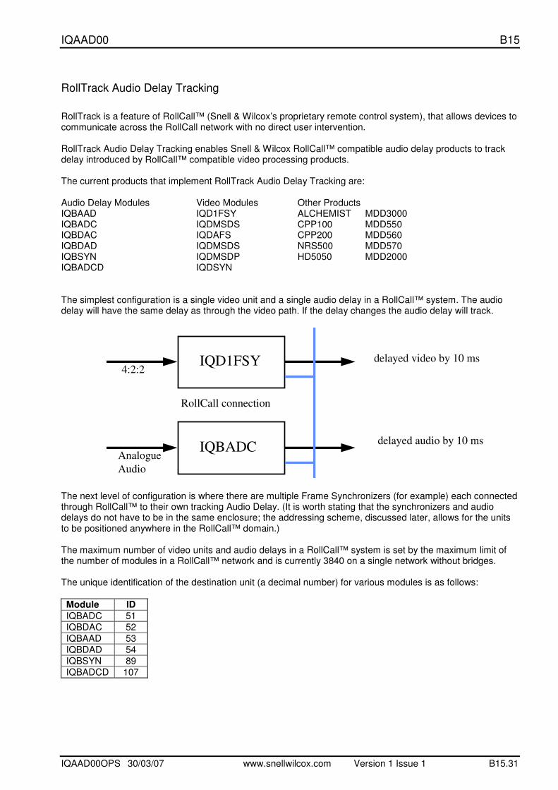
RollTrack Audio Delay Tracking RollTrack is a feature of RollCall™ (Snell & Wilcox’s proprietary remote control system), that allows devices to communicate across the RollCall network with no direct user intervention. RollTrack Audio Delay Tracking enables Snell & Wilcox RollCall™ compatible audio delay products to track delay introduced by RollCall™ compatible video processing products. The current products that implement RollTrack Audio Delay Tracking are: Audio Delay Modules Video Modules Other Products IQBAAD IQD1FSY ALCHEMIST MDD3000 IQBADC IQDMSDS CPP100 MDD550 IQBDAC IQDAFS CPP200 MDD560 IQBDAD IQDMSDS NRS500 MDD570 IQBSYN IQDMSDP HD5050 MDD2000 IQBADCD IQDSYN The simplest configuration is a single video unit and a single audio delay in a RollCall™ system. The audio delay will have the same delay as through the video path. If the delay changes the audio delay will track.
IQD1FSY
IQBADC
RollCall connection
4:2:2
Analogue
Audio
delayed video by 10 ms
delayed audio by 10 ms
The next level of configuration is where there are multiple Frame Synchronizers (for example) each connected through RollCall™ to their own tracking Audio Delay. (It is worth stating that the synchronizers and audio delays do not have to be in the same enclosure; the addressing scheme, discussed later, allows for the units to be positioned anywhere in the RollCall™ domain.) The maximum number of video units and audio delays in a RollCall™ system is set by the maximum limit of the number of modules in a RollCall™ network and is currently 3840 on a single network without bridges. The unique identification of the destination unit (a decimal number) for various modules is as follows:
Module ID
IQBADC 51
IQBDAC 52
IQBAAD 53
IQBDAD 54
IQBSYN 89
IQBADCD 107
IQAAD00 B15
IQAAD00OPS 30/03/07 www.snellwilcox.com Version 1 Issue 1 B15.32
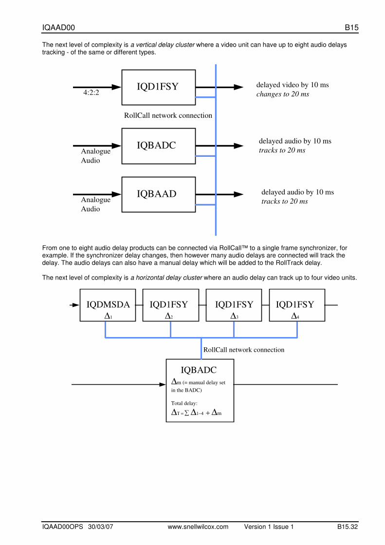
The next level of complexity is a vertical delay cluster where a video unit can have up to eight audio delays tracking - of the same or different types.
IQD1FSY
IQBADC
IQBAAD
RollCall network connection
4:2:2
Analogue
Audio
Analogue
Audio
delayed video by 10 ms
changes to 20 ms
delayed audio by 10 ms
tracks to 20 ms
delayed audio by 10 ms
tracks to 20 ms
From one to eight audio delay products can be connected via RollCall™ to a single frame synchronizer, for example. If the synchronizer delay changes, then however many audio delays are connected will track the delay. The audio delays can also have a manual delay which will be added to the RollTrack delay. The next level of complexity is a horizontal delay cluster where an audio delay can track up to four video units.
IQDMSDA
∆1
IQD1FSY
∆2
IQD1FSY
∆3
IQD1FSY
∆4
IQBADC
∆m (= manual delay set
in the BADC)
Total delay:
∆Τ = ∑ ∆1−4 + ∆m
RollCall network connection
IQAAD00 B15
IQAAD00OPS 30/03/07 www.snellwilcox.com Version 1 Issue 1 B15.33
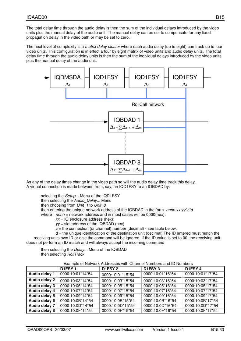
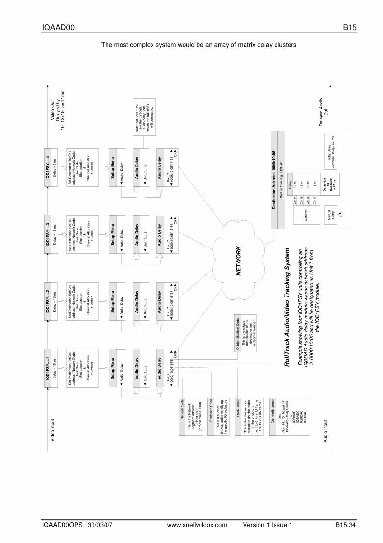
The total delay time through the audio delay is then the sum of the individual delays introduced by the video units plus the manual delay of the audio unit. The manual delay can be set to compensate for any fixed propagation delay in the video path or may be set to zero. The next level of complexity is a matrix delay cluster where each audio delay (up to eight) can track up to four video units. This configuration is in effect a four by eight matrix of video units and audio delay units. The total delay time through the audio delay units is then the sum of the individual delays introduced by the video units plus the manual delay of the audio unit.
IQDMSDA
∆1
IQD1FSY
∆2
IQD1FSY
∆3
IQD1FSY
∆4
IQBDAD 1
∆Τ = ∑ ∆1−4 + ∆m
RollCall networkconnection
IQBDAD 8
∆Τ = ∑ ∆1−4 + ∆m
As any of the delay times change in the video path so will the audio delay time track this delay. A virtual connection is made between from, say, an IQD1FSY to an IQBDAD by: selecting the Setup... Menu of the IQD1FSY then selecting the Audio_Delay... Menu then choosing from Unit_1 to Unit_8 then entering the unique network address of the IQBDAD in the form nnnn:xx:yy*z*d where nnnn = network address and in most cases will be 0000(hex); xx = IQ enclosure address (hex); yy = slot address of the IQBDAD (hex) z = the connection (or channel) number (decimal) - see table below. d = the unique identification of the destination unit (decimal) The ID entered must match the
receiving units own ID or else the command will be ignored. If the ID value is set to 00, the receiving unit does not perform an ID match and will always accept the incoming command
then selecting the Delay... Menu of the IQBDAD then selecting RollTrack Example of Network Addresses with Channel Numbers and ID Numbers
D1FSY 1 D1FSY 2 D1FSY 3 D1FSY 4
Audio delay 1 0000:10:01*14*54 0000:10:01*15*54 0000:10:01*16*54 0000:10:01*17*54
Audio delay 2 0000:10:03*14*54 0000:10:03*15*54 0000:10:03*16*54 0000:10:03*17*54
Audio delay 3 0000:10:05*14*54 0000:10:05*15*54 0000:10:05*16*54 0000:10:05*17*54
Audio delay 4 0000:10:07*14*54 0000:10:07*15*54 0000:10:07*16*54 0000:10:07*17*54
Audio delay 5 0000:10:09*14*54 0000:10:09*15*54 0000:10:09*16*54 0000:10:09*17*54
Audio delay 6 0000:10:0B*14*54 0000:10:0B*15*54 0000:10:0B*16*54 0000:10:0B*17*54
Audio delay 7 0000:10:0D*14*54 0000:10:0D*15*54 0000:10:0D*16*54 0000:10:0D*17*54
Audio delay 8 0000:10:0F*14*54 0000:10:0F*15*54 0000:10:0F*16*54 0000:10:0F*17*54
IQAAD00 B15
IQAAD00OPS 30/03/07 www.snellwilcox.com Version 1 Issue 1 B15.34
The most complex system would be an array of matrix delay clusters

IQAAD00 B15
IQAAD00OPS 30/03/07 www.snellwilcox.com Version 1 Issue 1 B15.35
IQAAD00 B15
IQAAD00OPS 30/03/07 www.snellwilcox.com Version 1 Issue 1 B15.36
Manual Revision Record
Date Version No. Issue No. Change Comments
300307 1 1 First issue released