4. access network technologies - abcd.lk
TRANSCRIPT

����
�
4. Access Network Technologies
4.1 Introduction
A main component of a public network is Access network. The Access network is connected to the core network. Customers are connected to the core network via the Access network. In other words this is the section between customer premises and service provider premises. Normally the length of the Access network can be in the range of 0.5km to 5km. Therefore this is also called “Subscriber Loop”. Also it is called ‘last mile access’. The Access network transmission media can be copper fiber or radio.
4.2 Copper Access Network This was originally designed for the PSTN network where telephone is connected to the telephone exchange.
Normally two copper wires are required for transmit and another two wire are required for receive. This is called a 4 wire (4w) circuit. However in order reduce the amount of copper wires, only two wires (2w) are used in the local loop for both transmit and receive (simplex). At the exchange 4w/2w and 2w/4w connection is done.

�����
�
4.2.1 4w/2w Connection using a bridge circuit
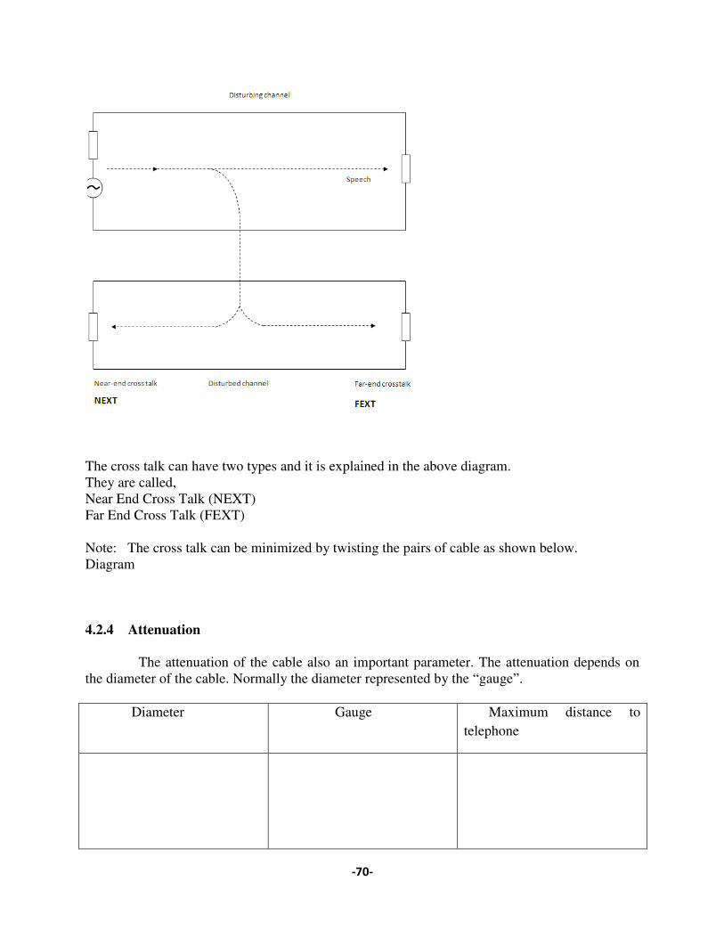
4.2.2 Echoes In a 4wire crcuit part of the signal energy transmitted in one direction may return in the other direction. Both the talker and the listner may be here the reflected signal and the effect is called ‘echo’. In order to minimize the echo, “echo suppressor” or “echo canceller” is used at the telephone exchange for each circuit. 4.2.3 Cross talk (X talk) Multi pair cobles are used between telephone exchange and cabinet, also cabinet and DP. The signal of one pair can be induce in another 2wires. This effect is called “Cross talk”.
����
�
The cross talk can have two types and it is explained in the above diagram. They are called, Near End Cross Talk (NEXT) Far End Cross Talk (FEXT) Note: The cross talk can be minimized by twisting the pairs of cable as shown below. Diagram 4.2.4 Attenuation The attenuation of the cable also an important parameter. The attenuation depends on the diameter of the cable. Normally the diameter represented by the “gauge”. Diameter Gauge Maximum distance to
telephone

����
�
A telephone signal has a bandwidth of 0.3 - 3.4kHz.The table shows the maximum distance of a telephone signal works according to the gauge of the cable. 4.2.5 Noise Noise also another important parameter .The amount of noise depends on the insulation of a cable and the distance. The quality of the signal measured as S/N. 4.2.6 Characteristic Impedance The characteristic Impedance [Zo] of a cable is defined as,
The Characteristic Impedance can be calculated from the above equation. Typical charateristic impendences are 75, 120, 150, 300 ohms. When cable is joint to another cable or to end device the impedance should be matched. If not a part of signal can be reflected. 4.2.7 Telephone Connected to exchange
The bandwidth of the signal is 0.3 – 3.4 khz.The distance between the telephone and exchange can be increased by using a low gauge cable. Further increase the distance can be done by using. Line amplifier or repeater.
"#������$%ω��
���������&$�%ω��
����
�
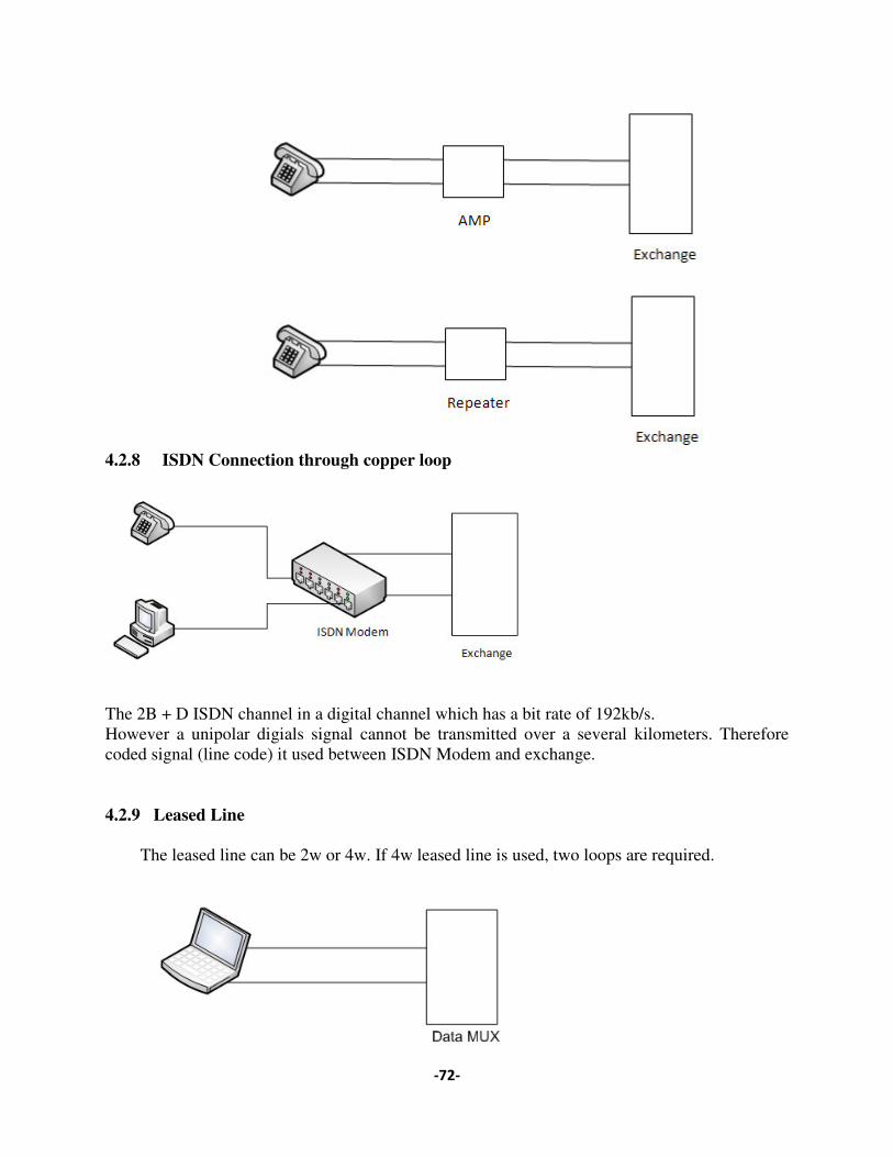
4.2.8 ISDN Connection through copper loop
The 2B + D ISDN channel in a digital channel which has a bit rate of 192kb/s. However a unipolar digials signal cannot be transmitted over a several kilometers. Therefore coded signal (line code) it used between ISDN Modem and exchange. 4.2.9 Leased Line The leased line can be 2w or 4w. If 4w leased line is used, two loops are required.
����
�
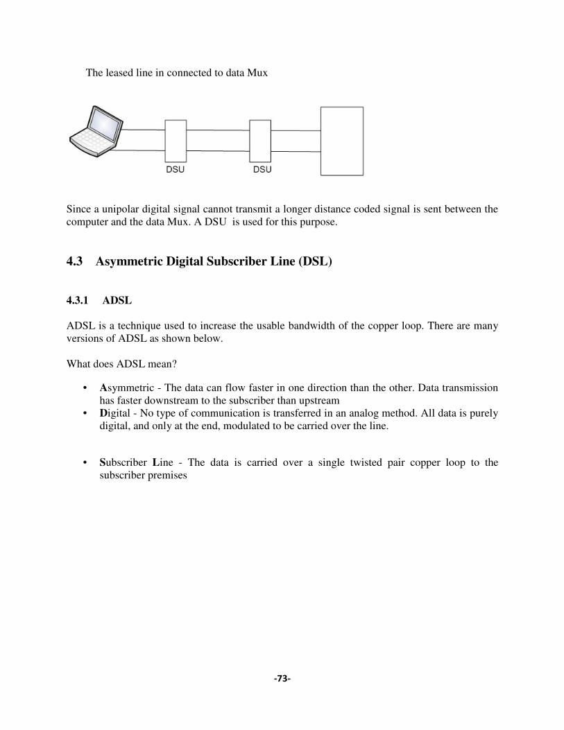
The leased line in connected to data Mux
Since a unipolar digital signal cannot transmit a longer distance coded signal is sent between the computer and the data Mux. A DSU is used for this purpose. 4.3 Asymmetric Digital Subscriber Line (DSL) 4.3.1 ADSL ADSL is a technique used to increase the usable bandwidth of the copper loop. There are many versions of ADSL as shown below. What does ADSL mean?
• Asymmetric - The data can flow faster in one direction than the other. Data transmission has faster downstream to the subscriber than upstream
• Digital - No type of communication is transferred in an analog method. All data is purely digital, and only at the end, modulated to be carried over the line.
• Subscriber Line - The data is carried over a single twisted pair copper loop to the subscriber premises

����
�
ADSL standards:
Standard name Common name Downstream rate
Upstream rate
ITU G.992.1 ADSL (G.DMT) 8 Mbit/s 1.0 Mbit/s
ITU G.992.2 ADSL Lite (G.Lite) 1.5 Mbit/s 0.5 Mbit/s
ITU G.992.3/4 ADSL2 12 Mbit/s 1.0 Mbit/s
ITU G.992.3/4 Annex J ADSL2 12 Mbit/s 3.5 Mbit/s
ITU G.992.3/4 Annex L RE-ADSL2 5 Mbit/s 0.8 Mbit/s
ITU G.992.5 ADSL2+ 24 Mbit/s 1.0 Mbit/s
ITU G.992.5 Annex L RE-ADSL2+ 24 Mbit/s 1.0 Mbit/s
ITU G.992.5 Annex M ADSL2+ 28 Mbit/s 3.5 Mbit/s
ADSL Range
• In general, the maximum range for DSL without a repeater is 5.5 km • As distance decreases toward the telephone company office, the data rate increases
Data Rate Wire gauge Wire size Distance
1.5 or 2 Mbps 24 AWG 0.5 mm 5.5 km
1.5 or 2 Mbps 26 AWG 0.4 mm 4.6 km
6.1 Mbps 24 AWG 0.5 mm 3.7 km
1.5 or 2 Mbps 26 AWG 0.4 mm 2.7
• For larger distances, you may be able to have DSL if your phone company has extended
the local loop with optical fiber cable
ADSL Speed Factors
• The distance from the local exchange • The type and thickness of wires used

����
�
4 25,875 138 1104 KHz
PPSSTTNN DDoowwnnssttrreeaaUUppssttrreeaamm
• The number and type of joins in the wire • The proximity of the wire to other wires carrying ADSL, ISDN and other non-voice
signals • The proximity of the wires to radio transmitters.
ADSL network components
• The ADSL modem at the customer premises(ATU-R) • The modem of the central office (ATU-C) • DSL access multiplexer (DSLAM) • Broadband Access Server (BAS) • Splitter - an electronic low pass filter that separates the analogue voice or ISDN signal
from ADSL data frequencies DSLAM.
ADSL Loop Architecture
ADSL Requirements
• Phone-line, activated by your phone company for ADSL • Filter to separate the phone signal from the Internet signal • ADSL modem • Subscription with an ISP supporting ADSL
How does ADSL work
• ADSL exploits the unused analogue bandwidth available in the wires
�
• ADSL works by using a frequency splitter device to split a traditional voice telephone line into two frequencies
ADSL Modulation
• Modulation is the overlaying of carrier waveform
• There are two competing and incompatible standards for modulating the ADSL signal:– Carrierless Amplitude Phase (CAP)– Discrete Multi-Tone (DMT)
Carrierless Amplitude Phase
• Carrierless Amplitude Phase (CAP) is an encoding method that divides the signals into two distinct bands:
1. The upstream data channel (to the service provider), which is carried in the band between 25 and 160kHz
1. The downstream data channel (to the user), which is
200kHz to 1.1MHz .
• These channels are widely separated in order to minimize the possibility of interference between the channels.
Discrete Multi-tone (DMT)
• Discrete Multi-Tone (DMT) separates the DSL signal so that the usable is separated into 256 channels of 4.3125kHz each.
• DMT has 224 downstream frequency bins (or carriers) and 32 upstream frequency bins. • DMT constantly shifts signals between different channels to ensure that the best channels
are used for transmission and reception.
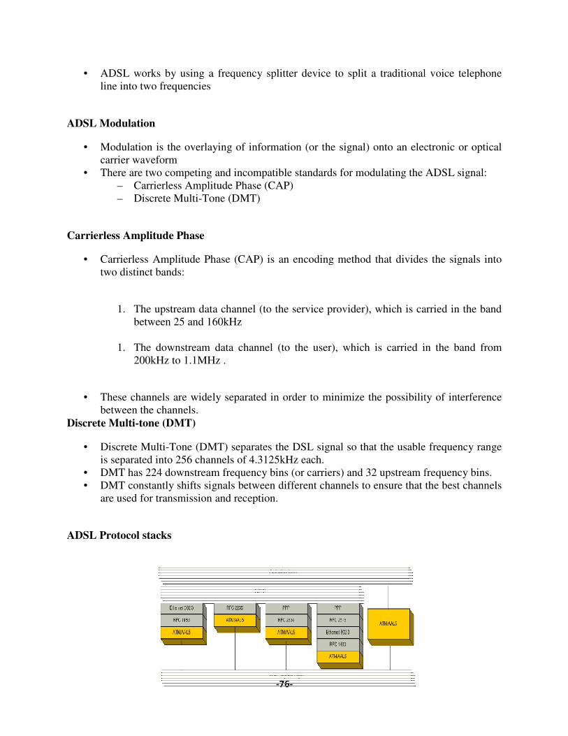
ADSL Protocol stacks
����
ADSL works by using a frequency splitter device to split a traditional voice telephone
Modulation is the overlaying of information (or the signal) onto an electronic or optical
There are two competing and incompatible standards for modulating the ADSL signal:Carrierless Amplitude Phase (CAP)
Tone (DMT)
ss Amplitude Phase (CAP) is an encoding method that divides the signals into
The upstream data channel (to the service provider), which is carried in the band between 25 and 160kHz
The downstream data channel (to the user), which is carried in the band from 200kHz to 1.1MHz .
These channels are widely separated in order to minimize the possibility of interference
Tone (DMT) separates the DSL signal so that the usable is separated into 256 channels of 4.3125kHz each. DMT has 224 downstream frequency bins (or carriers) and 32 upstream frequency bins. DMT constantly shifts signals between different channels to ensure that the best channels
ansmission and reception.
ADSL works by using a frequency splitter device to split a traditional voice telephone
information (or the signal) onto an electronic or optical
There are two competing and incompatible standards for modulating the ADSL signal:
ss Amplitude Phase (CAP) is an encoding method that divides the signals into
The upstream data channel (to the service provider), which is carried in the band
carried in the band from
These channels are widely separated in order to minimize the possibility of interference
Tone (DMT) separates the DSL signal so that the usable frequency range
DMT has 224 downstream frequency bins (or carriers) and 32 upstream frequency bins. DMT constantly shifts signals between different channels to ensure that the best channels

���
�
4.4 WIMAX What is WiMAX?
� Worldwide Interoperability for Microwave Access (WiMAX) is the common name associated to the IEEE 802.16a/REVd/e standards.
� These standards are issued by the IEEE 802.16 subgroup that originally covered the Wireless Local Loop technologies with radio spectrum from 10 to 66 GHz.
IEEE 802.16 -- Introduction
� IEEE 802.16 (2001) � Air Interface for Fixed Broadband Wireless Access System MAC and PHY
Specifications for 10 – 66 GHZ (LoS) � One PHY: Single Carrier � Connection-oriented, TDM/TDMA MAC, QoS, Privacy
� IEEE 802.16a (January 2003) � Amendment to 802.16, MAC Modifications and Additional PHY Specifications
for 2 – 11 GHz (NLoS) � Three PHYs: OFDM, OFDMA, Single Carrier � Additional MAC functions: OFDM and OFDMA PHY support, Mesh topology
support, ARQ
� IEEE 802.16d (July 2004) � Combines both IEEE 802.16 and 802.16a � Some modifications to the MAC and PHY
� IEEE 802.16e (2005?) � Amendment to 802.16-2004 � MAC Modifications for limited mobility
IEEE 802.16 -- Introduction
Coverage range up to 50km and speeds up to 70Mbps(shared among users).

�
IEEE 802.16 -- Introduction
Reference Model
Adaptive PHY
���

����
�
Duplex Scheme Support
� The duplex scheme is Usually specified by regulatory bodies, e.g., FCC � Time-Division Duplex (TDD)
� Downlink & Uplink time share the same RF channel � Dynamic asymmetry � does not transmit & receive simultaneously (low cost)
� Frequency-Division Duplex (FDD) � Downlink & Uplink on separate RF channels � Full Duplexing (FDX): can Tx and Rx simultaneously; � Half-duplexing (HDX) SSs supported (low cost)
IEEE 802.16 MAC – OFDM PHY TDD Frame Structure
IEEE 802.16 MAC – OFDM PHY FDD Frame Structure
DL PHY PDU
Frame n-1
Contentionslot for initial
ranging
UL PHYPDU from
SS#1
...... UL PHY PDUfrom SS#K
Frame n Frame n+1 Frame n+2
Time
Preamble FCH DL Burst 1 DL Burst 2 ...... DL Burst M
Contentionslot for BW
Req.
Preamble UL Burst
one OFDM symbolwith the well-konwmodulation/coding{QPSK, (32, 24, 4)}
one or multiple DL bursts; each hasdifferent modulation/coding, transmittedin order of decreasing robustness.
one UL burst perUL PHY PHYPDU, transmittedin the modulation/coding specific tothe source SS.
DL Sub-frame UL Sub-frame
DL FrPrefix
DCD, UCD(optinal)
padding(optional)
Rate ID(4 bits)
llength(12 bits)
HCS(8 bits)
......MAC Msg 1(MAC PDU-1)
MAC Msg N(MAC PDU-N) Pad
MAC Header(6 bytes)
MAC Msg Payload(optional)
CRC(optional)
......MAC Msg 1(MAC PDU-1)
MAC Msg N(MAC PDU-N) Pad
MAC Header(6 bytes)
MAC Msg Payload(optional)
CRC(optional)
DL PHY PDU
Frame n-1
Contentionslot for initial
ranging
UL PHYPDU from
SS#1
...... UL PHY PDUfrom SS#K
Frame n Frame n+1 Frame n+2
Time
Preamble FCH DL Burst 1 DL Burst 2 ...... DL Burst M
Contentionslot for BW
Req.
Preamble UL Burst
one OFDM symbolwith the well-konwmodulation/coding{QPSK, (32, 24, 4)}
one or multiple DL bursts; each hasdifferent modulation/coding, transmittedin order of decreasing robustness.
one UL burst perUL PHY PHYPDU, transmittedin the modulation/coding specific tothe source SS.
DL Sub-frame UL Sub-frame
DL FrPrefix
DCD, UCD(optinal)
padding(optional)
Rate ID(4 bits)
llength(12 bits)
HCS(8 bits)
......MAC Msg 1(MAC PDU-1)
MAC Msg N(MAC PDU-N)
Pad
MAC Header(6 bytes)
MAC Msg Payload(optional)
CRC(optional)
......MAC Msg 1(MAC PDU-1)
MAC Msg N(MAC PDU-N) Pad
MAC Header(6 bytes)
MAC Msg Payload(optional)
CRC(optional)
����
�
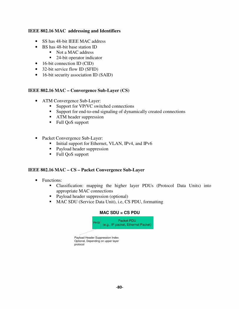
IEEE 802.16 MAC addressing and Identifiers
• SS has 48-bit IEEE MAC address • BS has 48-bit base station ID
� Not a MAC address � 24-bit operator indicator
• 16-bit connection ID (CID) • 32-bit service flow ID (SFID) • 16-bit security association ID (SAID)
IEEE 802.16 MAC – Convergence Sub-Layer (CS)
• ATM Convergence Sub-Layer: � Support for VP/VC switched connections � Support for end-to-end signaling of dynamically created connections � ATM header suppression � Full QoS support
• Packet Convergence Sub-Layer: � Initial support for Ethernet, VLAN, IPv4, and IPv6 � Payload header suppression � Full QoS support
IEEE 802.16 MAC – CS – Packet Convergence Sub-Layer
• Functions: � Classification: mapping the higher layer PDUs (Protocol Data Units) into
appropriate MAC connections � Payload header suppression (optional) � MAC SDU (Service Data Unit), i.e, CS PDU, formatting
Packet PDU(e.g., IP packet, Ethernet Packet)
PHSI
MAC SDU = CS PDU
Payload Header Suppression IndexOptional, Depending on upper layerprotocol

����
�
IEEE 802.16 MAC – CPS – MAC PDU Format
IEEE 802.16 MAC -- CPS -- Three Types of MAC PDUs
• Data MAC PDUs � HT = 0 � Payloads are MAC SDUs/segments, i.e., data from upper layer (CS PDUs) � Transmitted on data connections
• Management MAC PDUs � HT =0 � Payloads are MAC management messages or IP packets encapsulated in MAC CS
PDUs � Transmitted on management connections
• BW Req. MAC PDUs � HT =1; and no payload, i.e., just a Header
IEEE 802.16 MAC – CPS – Data Packet Encapsulations
CRC(optional)MAC PDU payload (optional)
Generic MACHeader
(6 bytes)
LENmsb(3)
HT
CID msb (8)LEN lsb (8)
Generic MAC Header Format(Header Type (HT) = 0)
BW Req. Header Format(Header Type (HT) =1)
msb lsb
EC Type (6 bits) rs
vCI
EKS(2)
rsv
HCS (8)CID lsb (8)
BW Req.msb (8)
HT
CID msb (8)BWS Req. lsb (8)
EC Type (6 bits)
HCS (8)CID lsb (8)
PHSI
MAC PDU
Ethernet Packet
Ethernet Packet
Packet PDU(e.g., Ethernet)
CS PDU(i.e., MAC SDU)
HT
FEC block 1
CRCMAC PDU Payload
OFDMsymbol
1
PHY Burst(e.g., TDMA burst)
PreambleOFDMsymbol
2
OFDMsymbol
n......
FEC FEC Block 2 FEC block m......FEC Block 3

����
�
IEEE 802.16 MAC – CPS -- MAC Management Connections
• Each SS has 3 management connections in each direction: o Basic Connection:
� short and time-urgent MAC management messages � MAC mgmt messages as MAC PDU payloads
o Primary Management connection: � longer and more delay tolerant MAC mgmt messages � MAC mgmt messages as MAC PDU payloads
o Secondary Management Connection: � Standard based mgmt messages, e.g., DHCP, SNMP, …etc � IP packets based CS PDU as MAC PDU payload
IEEE 802.16 MAC – CPS – MAC Management Messages
• MAC mgmt message format:
• MAC mgmt msg can be sent on: Basic connections; Primary mgmt connection; Broadcast connection; and initial ranging connections
• 41 MAC mgmt msgs specified in 802.16 • The TLV (type/length/value) encoding scheme is used in MAC mgmt msg, e.g., in UCD
msg for UL burst profiles, (type=1, length=1, value=1) � QPSK modulation
(type=1, length=1, value=2) � 16QAM modulation
(type=1, length=1, value=3) � 64QAM modulation
IEEE 802.16 MAC – CPS – MAC PDU Transmission
� MAC PDUs are transmitted in PHY Bursts � The PHY burst can contain multiple FEC blocks � MAC PDUs may span FEC block boundaries � Concatenation � Packing � Segmentation � Sub-headers
MAC mgmt msg payloadmgmtmsgHD
8 bits
�
4.5 Fibre To the x
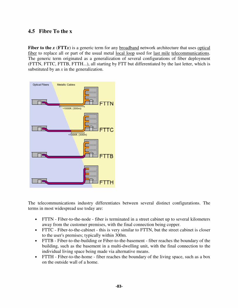
Fiber to the x (FTTx) is a generic term for any fiber to replace all or part of the usual metal The generic term originated as a generalization of several configurations of fiber deployment (FTTN, FTTC, FTTB, FTTH...), all starting by FTT but differentiasubstituted by an x in the generalization.
The telecommunications industry differentiates between several distinct configurations. The terms in most widespread use today are:
• FTTN - Fiber-to-the-node away from the customer premises, with the final connection being copper.
• FTTC - Fiber-to-the-cabinet to the user's premises; typically within 30
• FTTB - Fiber-to-the-building or Fiberbuilding, such as the basement in a multiindividual living space being made via alternative means.
• FTTH - Fiber-to-the-home on the outside wall of a home.
����
) is a generic term for any broadband network architecture that uses to replace all or part of the usual metal local loop used for last mile telecommunications
The generic term originated as a generalization of several configurations of fiber deployment (FTTN, FTTC, FTTB, FTTH...), all starting by FTT but differentiated by the last letter, which is
in the generalization.
The telecommunications industry differentiates between several distinct configurations. The terms in most widespread use today are:
node - fiber is terminated in a street cabinet up to several kilometers away from the customer premises, with the final connection being copper.
cabinet - this is very similar to FTTN, but the street cabinet is closer to the user's premises; typically within 300m.
building or Fiber-to-the-basement - fiber reaches the boundary of the building, such as the basement in a multi-dwelling unit, with the final connection to the individual living space being made via alternative means.
home - fiber reaches the boundary of the living space, such as a box on the outside wall of a home.
network architecture that uses optical telecommunications.
The generic term originated as a generalization of several configurations of fiber deployment ted by the last letter, which is
The telecommunications industry differentiates between several distinct configurations. The
in a street cabinet up to several kilometers away from the customer premises, with the final connection being copper.
this is very similar to FTTN, but the street cabinet is closer
fiber reaches the boundary of the dwelling unit, with the final connection to the
fiber reaches the boundary of the living space, such as a box
����
�
• FTTP - Fiber-to-the premises - this term is used in several contexts: as a blanket term for both FTTH and FTTB, or where the fiber network includes both homes and small businesses.
To promote consistency, especially when comparing FTTH penetration rates between countries, the three FTTH Councils of Europe, North America and Asia-Pacific have agreed upon definitions for FTTH and FTTB.[1] The FTTH Councils do not have formal definitions for FTTC and FTTN.
It is worth pointing out that fiber to the telecom enclosure (FTTE) is not considered to be part of the FTTx group of technologies, despite the similarity in name. FTTE is a form of structured cabling typically used in the enterprise local area network, where fiber is used to link the main computer equipment room to an enclosure close to the desk or workstation.[2] Similarly, in fiber-to-the-desk a fiber connection is installed from the main computer room to a terminal at the desk.
4.5.1 Electrical portion
Once on private property, the signal typically travels the final distance to the end user's equipment using an electrical format.
A device called an Optical Network Terminal (ONT), also called an Optical Network Unit (ONU), converts the optical signal into an electrical signal. (ONT is an ITU-T term, whereas ONU is an IEEE term, but the two terms mean exactly the same thing.) Optical network terminals require electrical power for their operation, so some providers connect them to back-up batteries in case of power outages. Optical network units use thin film filter technology to convert between optical and electrical signals.
For fiber to the home and for some forms of fiber to the building, it is common for the building's existing phone systems, local area networks, and cable TV systems to connect directly to the ONT.
If all three systems cannot directly reach the ONT, it is possible to combine signals and transport them over a common medium. Once closer to the end-user, equipment such as a router, modem, and/or network interface module can separate the signals and convert them into the appropriate protocol. For example, one solution for apartment buildings uses VDSL to combine data (and / or video) with voice. With this approach, the combined signal travels through the building over the existing telephone wiring until it reaches the end-user's living space. Once there, a VDSL modem copies the data and video signals and converts them into Ethernet protocol. These are then sent over the end user's category 5 cable. A network interface module can then separate out the video signal and convert it into an RF signal that is sent over the end-user's coaxial cable. The voice signal continues to travel over the phone wiring and is sent through DSL filters to remove the video and data signals. An alternative strategy allows data and / or voice to be transmitted over coaxial cable. In yet another strategy, some office buildings dispense with the

����
�
telephone wiring altogether, instead using voice over Internet Protocol phones that can plug directly into the local area network.
4.5.2 Direct fiber
The simplest optical distribution network can be called direct fiber. In this architecture, each fiber leaving the central office goes to exactly one customer. Such networks can provide excellent bandwidth since each customer gets their own dedicated fiber extending all the way to the central office. However, this approach is about 10% more costly due to the amount of fiber and central office machinery required.[8] The approach is generally favored by new entrants and competitive operators. A benefit of this approach is that it doesn't exclude any layer 2 networking technologies, be they Passive optical network, Active Optical Network, etc. From a regulatory point of view it leads to least implications as any form of regulatory remedy is still possible using this topology.[9]
Shared fiber
More commonly each fiber leaving the central office is actually shared by many customers. It is not until such a fiber gets relatively close to the customers that it is split into individual customer-specific fibers. There are two competing optical distribution network architectures which achieve this split: active optical networks (AONs) and passive optical networks (PONs).
�
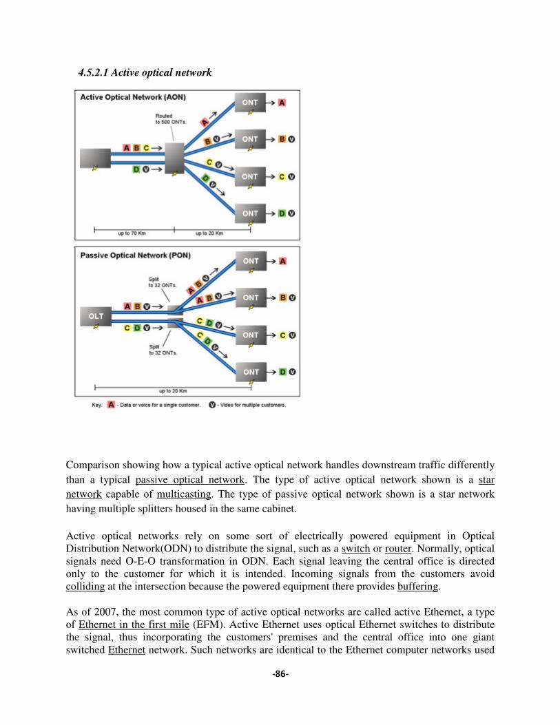
4.5.2.1 Active optical network
Comparison showing how a typical active optical network handles downstream traffic differently than a typical passive optical networknetwork capable of multicastinghaving multiple splitters housed in the same cabinet.
Active optical networks rely on some sort of electrically powered equipment in Optical Distribution Network(ODN) to distribute the signal, such as a signals need O-E-O transformation in ODN. Each signal leaving the central office is directed only to the customer for which it is intended. Incoming signals from the customers avoid colliding at the intersection because the powered equipment there provid
As of 2007, the most common type of active optical networks are called active Ethernet, a type of Ethernet in the first mile (EFM). Active Ethernet uses optical Ethernet switches to distribute the signal, thus incorporating the customers' premises and the central office into one giant switched Ethernet network. Such networks are identical to the Ethernet computer networks used
����
Active optical network
Comparison showing how a typical active optical network handles downstream traffic differently passive optical network. The type of active optical network shown is a
multicasting. The type of passive optical network shown is a star network having multiple splitters housed in the same cabinet.
Active optical networks rely on some sort of electrically powered equipment in Optical Distribution Network(ODN) to distribute the signal, such as a switch or router. Normally, optical
O transformation in ODN. Each signal leaving the central office is directed tomer for which it is intended. Incoming signals from the customers avoid
at the intersection because the powered equipment there provides buffering
As of 2007, the most common type of active optical networks are called active Ethernet, a type (EFM). Active Ethernet uses optical Ethernet switches to distribute
the signal, thus incorporating the customers' premises and the central office into one giant network. Such networks are identical to the Ethernet computer networks used
Comparison showing how a typical active optical network handles downstream traffic differently . The type of active optical network shown is a star
ical network shown is a star network
Active optical networks rely on some sort of electrically powered equipment in Optical . Normally, optical
O transformation in ODN. Each signal leaving the central office is directed tomer for which it is intended. Incoming signals from the customers avoid
buffering.
As of 2007, the most common type of active optical networks are called active Ethernet, a type (EFM). Active Ethernet uses optical Ethernet switches to distribute
the signal, thus incorporating the customers' premises and the central office into one giant network. Such networks are identical to the Ethernet computer networks used

���
�
in businesses and academic institutions, except that their purpose is to connect homes and buildings to a central office rather than to connect computers and printers within a campus. Each switching cabinet can handle up to 1,000 customers, although 400-500 is more typical. This neighborhood equipment performs layer 2/layer 3 switching and routing, offloading full layer 3 routing to the carrier's central office. The IEEE 802.3ah standard enables service providers to deliver up to 100 Mbit/s full-duplex over one single-mode optical fiber to the premises depending on the provider. Speeds of 1Gbit/s are becoming commercially available.
4.5.2.2 Passive optical network
Main article: Passive optical network
A passive optical network (PON) is a point-to-multipoint, fiber to the premises network architecture in which unpowered optical splitters are used to enable a single optical fiber to serve multiple premises, typically 32-128. A PON configuration reduces the amount of fiber and central office equipment required compared with point to point architectures.
Downstream signal coming from the central office is broadcast to each customer premises sharing a fiber. Encryption is used to prevent eavesdropping.
Upstream signals are combined using a multiple access protocol, invariably time division multiple access (TDMA). The OLTs "range" the ONUs in order to provide time slot assignments for upstream communication.
4.5.3 Electrical portion
Once on private property, the signal typically travels the final distance to the end user's equipment using an electrical format.
A device called an Optical Network Terminal (ONT), also called an Optical Network Unit (ONU), converts the optical signal into an electrical signal. (ONT is an ITU-T term, whereas ONU is an IEEE term, but the two terms mean exactly the same thing.) Optical network terminals require electrical power for their operation, so some providers connect them to back-up batteries in case of power outages. Optical network units use thin film filter technology to convert between optical and electrical signals.
For fiber to the home and for some forms of fiber to the building, it is common for the building's existing phone systems, local area networks, and cable TV systems to connect directly to the ONT.
If all three systems cannot directly reach the ONT, it is possible to combine signals and transport them over a common medium. Once closer to the end-user, equipment such as a router, modem, and/or network interface module can separate the signals and convert them into the appropriate

���
�
protocol. For example, one solution for apartment buildings uses VDSL to combine data (and / or video) with voice. With this approach, the combined signal travels through the building over the existing telephone wiring until it reaches the end-user's living space. Once there, a VDSL modem copies the data and video signals and converts them into Ethernet protocol. These are then sent over the end user's category 5 cable. A network interface module can then separate out the video signal and convert it into an RF signal that is sent over the end-user's coaxial cable. The voice signal continues to travel over the phone wiring and is sent through DSL filters to remove the video and data signals. An alternative strategy allows data and / or voice to be transmitted over coaxial cable. In yet another strategy, some office buildings dispense with the telephone wiring altogether, instead using voice over Internet Protocol phones that can plug directly into the local area network.
4.6 Metro Ethernet
A Metro Ethernet is a computer network that covers a metropolitan area and that is based on the Ethernet standard. It is commonly used as a metropolitan access network to connect subscribers and businesses to a larger service network or the Internet. Businesses can also use Metro Ethernet to connect branch offices to their Intranet.
Ethernet has been a well known technology for decades. An Ethernet interface is much less expensive than a SONET/SDH or PDH interface of the same bandwidth. Ethernet also supports high bandwidths with fine granularity,[clarification needed] which is not available with traditional SDH connections. Another distinct advantage of an Ethernet-based access network is that it can be easily connected to the customer network, due to the prevalent use of Ethernet in corporate and, more recently, residential networks. Therefore, bringing Ethernet in to the Metropolitan Area Network (MAN) introduces a lot of advantages to both the service provider and the customer (corporate and residential)
A typical service provider Metro Ethernet network is a collection of Layer 2 or/and Layer 3 switches or/and routers connected through optical fiber. The topology could be a ring, hub-and-spoke (star), or full or partial mesh. The network will also have a hierarchy: core, distribution (aggregation) and access. The core in most cases is an existing IP/MPLS backbone, but may migrate to newer forms of Ethernet Transport in the form of 10G or 100G speeds.
Ethernet on the MAN can be used as pure Ethernet, Ethernet over SDH, Ethernet over MPLS or Ethernet over DWDM. Pure Ethernet-based deployments are cheap but less reliable and scalable, and thus are usually limited to small scale or experimental deployments. SDH-based deployments are useful when there is an existing SDH infrastructure already in place, its main shortcoming being the loss of flexibility in bandwidth management due to the rigid hierarchy imposed by the SDH network. MPLS based deployments are costly but highly reliable and scalable, and are typically used by large service providers.
The Metro Ethernet Forum (MEF) has defined three types of services that can be delivered through Metro Ethernet:
����
�
• E-Line also known as Virtual Private Wire Service (VPWS), Virtual Leased Line (VLL), Point-to-Point, or Ethernet Private Wire Service (EPVS).
• E-LAN also known as Virtual Private LAN Services (VPLS), Transparent LAN Services and MultiPoint-to-MultiPoint.
• E-TREE also known as Rooted-MultiPoint.
5. Core Network Technologies
5.1 Introduction
The core network is similar to highways of a road network. The highway network connects the major towns of the country by using highways which consists of wide roads. This road is shared by many vehicles.
The core network of a communication network is own and managed by the service providers. They look after the redundancy, reliability, availability etc. of the core network. If one route has a problem it will be switched to an alternative route. If one route to a particular destination has high traffic, another route also can be used to the same destination. Normally such things are managed by a protocol used in the network.