3rv1 circuit-breakers for motor protection • up to 25 a · 2/2 siemens ns k · 2000 for motor...
TRANSCRIPT
2/2 Siemens NS K · 2000
for Motor Protection · up to 25 A
Selection and ordering data
3RV1 Circuit-Breakers
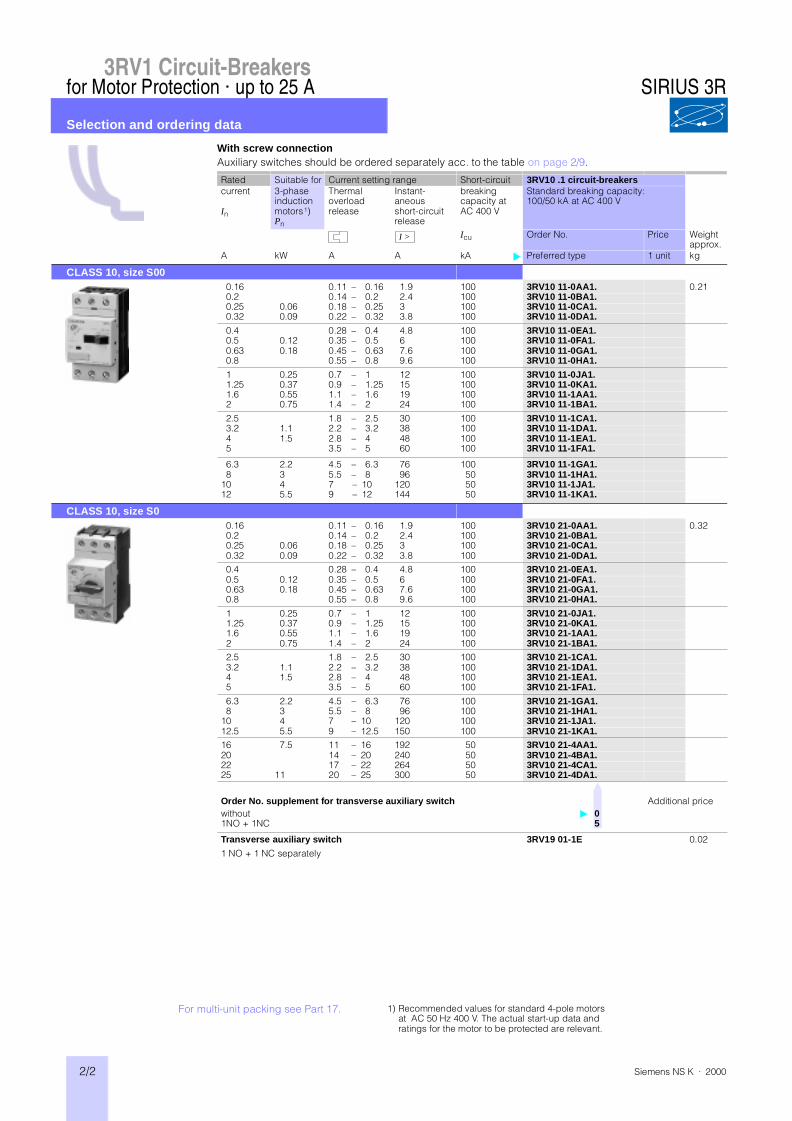
3RV1 Circuit-Breakers With screw connection
Auxiliary switches should be ordered separately acc. to the table on page 2/9.
Rated Suitable for Current setting range Short-circuit 3RV10 .1 circuit-breakerscurrent
In
3-phaseinductionmotors1)Pn
Thermaloverloadrelease
Instant-aneousshort-circuitrelease
breakingcapacity atAC 400 V
Standard breaking capacity:100/50 kA at AC 400 V
Icu Order No. Price Weightapprox.
A kW A A kA Preferred type 1 unit kg
CLASS 10, size S000.16 0.11 – 0.16 1.9 100 3RV10 11-0AA1. 0.210.2 0.14 – 0.2 2.4 100 3RV10 11-0BA1.0.25 0.06 0.18 – 0.25 3 100 3RV10 11-0CA1.0.32 0.09 0.22 – 0.32 3.8 100 3RV10 11-0DA1.
0.4 0.28 – 0.4 4.8 100 3RV10 11-0EA1.0.5 0.12 0.35 – 0.5 6 100 3RV10 11-0FA1.0.63 0.18 0.45 – 0.63 7.6 100 3RV10 11-0GA1.0.8 0.55 – 0.8 9.6 100 3RV10 11-0HA1.
1 0.25 0.7 – 1 12 100 3RV10 11-0JA1.1.25 0.37 0.9 – 1.25 15 100 3RV10 11-0KA1.1.6 0.55 1.1 – 1.6 19 100 3RV10 11-1AA1.2 0.75 1.4 – 2 24 100 3RV10 11-1BA1.
2.5 1.8 – 2.5 30 100 3RV10 11-1CA1.3.2 1.1 2.2 – 3.2 38 100 3RV10 11-1DA1.4 1.5 2.8 – 4 48 100 3RV10 11-1EA1.5 3.5 – 5 60 100 3RV10 11-1FA1.
6.3 2.2 4.5 – 6.3 76 100 3RV10 11-1GA1.8 3 5.5 – 8 96 50 3RV10 11-1HA1.
10 4 7 – 10 120 50 3RV10 11-1JA1.12 5.5 9 – 12 144 50 3RV10 11-1KA1.
CLASS 10, size S00.16 0.11 – 0.16 1.9 100 3RV10 21-0AA1. 0.320.2 0.14 – 0.2 2.4 100 3RV10 21-0BA1.0.25 0.06 0.18 – 0.25 3 100 3RV10 21-0CA1.0.32 0.09 0.22 – 0.32 3.8 100 3RV10 21-0DA1.0.4 0.28 – 0.4 4.8 100 3RV10 21-0EA1.0.5 0.12 0.35 – 0.5 6 100 3RV10 21-0FA1.0.63 0.18 0.45 – 0.63 7.6 100 3RV10 21-0GA1.0.8 0.55 – 0.8 9.6 100 3RV10 21-0HA1.
1 0.25 0.7 – 1 12 100 3RV10 21-0JA1.1.25 0.37 0.9 – 1.25 15 100 3RV10 21-0KA1.1.6 0.55 1.1 – 1.6 19 100 3RV10 21-1AA1.2 0.75 1.4 – 2 24 100 3RV10 21-1BA1.2.5 1.8 – 2.5 30 100 3RV10 21-1CA1.3.2 1.1 2.2 – 3.2 38 100 3RV10 21-1DA1.4 1.5 2.8 – 4 48 100 3RV10 21-1EA1.5 3.5 – 5 60 100 3RV10 21-1FA1.
6.3 2.2 4.5 – 6.3 76 100 3RV10 21-1GA1.8 3 5.5 – 8 96 100 3RV10 21-1HA1.
10 4 7 – 10 120 100 3RV10 21-1JA1.12.5 5.5 9 – 12.5 150 100 3RV10 21-1KA1.16 7.5 11 – 16 192 50 3RV10 21-4AA1.20 14 – 20 240 50 3RV10 21-4BA1.22 17 – 22 264 50 3RV10 21-4CA1.25 11 20 – 25 300 50 3RV10 21-4DA1.
Order No. supplement for transverse auxiliary switch Additional pricewithout 01NO + 1NC 5
Transverse auxiliary switch 3RV19 01-1E 0.02
1 NO + 1 NC separately
I >
SIRIUS 3R
For multi-unit packing see Part 17. 1) Recommended values for standard 4-pole motorsat AC 50 Hz 400 V. The actual start-up data andratings for the motor to be protected are relevant.
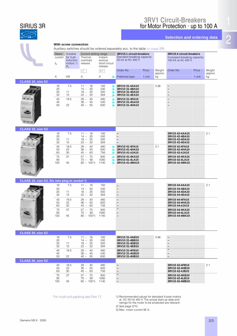
3RV1 Circuit-Breakers
2/3Siemens NS K · 2000
for Motor Protection · up to 100 A
Selection and ordering data
With screw connectionAuxiliary switches should be ordered separately acc. to the table on page 2/9.
Rated Suitable Current setting range 3RV10.1 circuit-breakersStandard breaking capacity:50 kA at AC 400 V
3RV10.4 circuit-breakerscurrent
In
for 3-ph.inductionmotors 1)Pn
Thermaloverloadrelease
Instant-aneousshort-circuitrelease
Increased breaking capacity:100 kA at AC 400 V
Order No. Price Weightapprox.
Order No. Price Weightapprox.
A kW A A Preferred type 1 unit kg 1 unit kg
CLASS 10, size S216 7.5 11 – 16 192 3RV10 31-4AA10 0.96 –20 14 – 20 240 3RV10 31-4BA10 –25 11 18 – 25 300 3RV10 31-4DA10 –32 15 22 – 32 384 3RV10 31-4EA10 –
40 18.5 28 – 40 480 3RV10 31-4FA10 –45 36 – 45 540 3RV10 31-4GA10 –50 22 40 – 50 600 3RV10 31-4HA10 –
CLASS 10, size S316 7.5 11 – 16 192 – 3RV10 42-4AA10 2.120 14 – 20 240 – 3RV10 42-4BA1025 11 18 – 25 300 – 3RV10 42-4DA1032 15 22 – 32 384 – 3RV10 42-4EA10
40 18.5 28 – 40 480 3RV10 41-4FA10 2.1 3RV10 42-4FA1050 22 36 – 50 600 3RV10 41-4HA10 3RV10 42-4HA1063 30 45 – 63 756 3RV10 41-4JA10 3RV10 42-4JA1075 37 57 – 75 900 3RV10 41-4KA10 3RV10 42-4KA1090 70 – 90 1080 3RV10 41-4LA10 3RV10 42-4LA10
100 45 80 – 100 3) 1140 3RV10 41-4MA10 3RV10 42-4MA10
CLASS 10, size S3, fits into plug-in socket 2)16 7.5 11 – 16 192 – 3RV10 44-4AA10 2.120 14 – 20 240 – 3RV10 44-4BA1025 11 18 – 25 300 – 3RV10 44-4DA1032 15 22 – 32 384 – 3RV10 44-4EA10
40 18.5 28 – 40 480 – 3RV10 44-4FA1050 22 36 – 50 600 – 3RV10 44-4HA1063 30 45 – 63 756 – 3RV10 44-4JA10
75 37 57 – 75 900 – 3RV10 44-4KA1090 70 – 90 1080 – 3RV10 44-4LA10
100 45 80 – 100 3) 1140 – 3RV10 44-4MA10
CLASS 20, size S216 7.5 11 – 16 192 3RV10 31-4AB10 0.96 –20 14 – 20 240 3RV10 31-4BB10 –25 11 18 – 25 300 3RV10 31-4DB10 –32 15 22 – 32 384 3RV10 31-4EB10 –
40 18.5 28 – 40 480 3RV10 31-4FB10 –
45 36 – 45 540 3RV10 31-4GB10 –50 22 40 – 50 600 3RV10 31-4HB10 –
CLASS 20, size S340 18.5 28 – 40 480 – 3RV10 42-4FB10 2.150 22 36 – 50 600 – 3RV10 42-4HB1063 30 45 – 63 756 – 3RV10 42-4JB10
75 37 57 – 75 900 – 3RV10 42-4KB1090 70 – 90 1080 – 3RV10 42-4LB10
100 45 80 – 100 3) 1140 – 3RV10 42-4MB10
I >
For multi-unit packing see Part 17. 1) Recommended values for standard 4-pole motorsat AC 50 Hz 400 V. The actual start-up data andratings for the motor to be protected are relevant.
2) See page 2/10.3) Max. motor current 95 A.
SIRIUS 3R

2/4 Siemens NS K · 2000
for Motor Protection · up to 100 A
Selection and ordering data
3RV1 Circuit-Breakers
With overload relay function · screw connection · without aux. switchesAuxiliary switches should be ordered separately acc. to the table on page 2/9.
Rated Suitable Current setting range Short- 3RV11 21 circuit-breakersStandard breaking capacity:100/50 kA at AC 400 V
current
In
for 3-ph.induct.motors1)
Pn
Thermal overload release
Instant-aneous short-circuit release
circuit breaking capacity atAC 400 V
Icu
Order No. Price Weightapprox.
A kW A A kA 1 unit kg
CLASS 10, size S0 without auxiliary switches 0.16 0.11–0.16 1.9 100 3RV11 21-0AA10 0.4
0.2 0.14 –0.2 2.4 100 3RV11 21-0BA100.25 0.06 0.18 –0.25 3 100 3RV11 21-0CA100.32 0.09 0.22 –0.32 3.8 100 3RV11 21-0DA10
0.4 0.28 –0.4 4.8 100 3RV11 21-0EA100.5 0.12 0.35 –0.5 6 100 3RV11 21-0FA100.63 0.18 0.45 –0.63 7.6 100 3RV11 21-0GA100.8 0.55 –0.8 9.6 100 3RV11 21-0HA10
1 0.25 0.7 – 1 12 100 3RV11 21-0JA101.25 0.37 0.9 – 1.25 15 100 3RV11 21-0KA101.6 0.55 1.1 – 1.6 19 100 3RV11 21-1AA102 0.75 1.4 – 2 24 100 3RV11 21-1BA10
2.5 1.8 – 2.5 30 100 3RV11 21-1CA103.2 1.1 2.2 – 3.2 38 100 3RV11 21-1DA104 1.5 2.8 – 4 48 100 3RV11 21-1EA105 3.5 – 5 60 100 3RV11 21-1FA10
6.3 2.2 4.5 – 6.3 76 100 3RV11 21-1GA108 3 5.5 – 8 96 100 3RV11 21-1HA10
10 4 7 – 10 120 100 3RV11 21-1JA1012.5 5.5 9 – 12.5 150 100 3RV11 21-1KA10
16 7.5 11 – 16 192 50 3RV11 21-4AA1020 14 – 20 240 50 3RV11 21-4BA1022 17 – 22 264 50 3RV11 21-4CA1025 11 20 – 25 300 50 3RV11 21-4DA10
Rated Suitable Current setting range 3RV11 31 circuit-breakersStandard breaking capacity:50 kA at AC 400 V
3RV11 42 circuit-breakerscurrent
In
for 3-ph. induction motors 1)Pn
Thermal overload release
Instant-aneous short-circuit release
Increased breaking capacity:100 kA at AC 400 V
Order No. Price Weightapprox.
Order No. Price Weightapprox.
A kW A A 1 unit kg 1 unit kg
CLASS 10, size S2without auxiliary switches 16 7.5 11 – 16 192 3RV11 31-4AA10 1.05 –
20 14 – 20 240 3RV11 31-4BA10 –25 11 18 – 25 300 3RV11 31-4DA10 –32 15 22 – 32 384 3RV11 31-4EA10 –
40 18.5 28 – 40 480 3RV11 31-4FA10 –45 36 – 45 540 3RV11 31-4GA10 –50 22 40 – 50 600 3RV11 31-4HA10 –
CLASS 10, size S3without auxiliary switches 16 7.5 11 – 16 192 – 3RV11 42-4AA10 2.2
20 14 – 20 240 – 3RV11 42-4BA1025 11 18 – 25 300 – 3RV11 42-4DA1032 15 22 – 32 384 – 3RV11 42-4EA10
40 18.5 28 – 40 480 – 3RV11 42-4FA1050 22 36 – 50 600 – 3RV11 42-4HA1063 30 45 – 63 756 – 3RV11 42-4JA1075 37 57 – 75 900 – 3RV11 42-4KA1090 70 – 90 1080 – 3RV11 42-4LA10
100 45 80 – 100 2) 1140 – 3RV11 42-4MA10
I >
I >
For multi-unit packing see Part 17. 1) Recommended values for standard 4-pole motorsat AC 50 Hz 400 V. The actual start-up data andratings for the motor to be protected are relevant.
2) Max. motor current 95 A.
SIRIUS 3R

3RV1 Circuit-Breakers
2/5Siemens NS K · 2000
for Starter Combinations · up to 100 A
Selection and ordering data
With screw connection · without auxiliary switchesAuxiliary switches should be ordered separately acc. to the table on page 2/9.
Rated Suitable Current setting range 3RV13.1 circuit-breakersStandard breaking capacity:50 kA at AC 400 V 3)
3RV13.2 circuit-breakerscurrent
In
for 3-ph.inductionmotors 1)Pn
Thermal overload release 2)
Instant-aneous short-circuit release
Increased breaking capacity:100 kA at AC 400 V
Order No. Price Weightapprox.
Order No. Price Weightapprox.
A kW A A 1 unit kg 1 unit kg
Class 10, size S00.16 without 1.9 3RV13 21-0AC10 0.32 –0.2 without 2.4 3RV13 21-0BC10 –0.25 0.06 without 3 3RV13 21-0CC10 –0.32 0.09 without 3.8 3RV13 21-0DC10 –
0.4 without 4.8 3RV13 21-0EC10 –0.5 0.12 without 6 3RV13 21-0FC10 –0.63 0.18 without 7.6 3RV13 21-0GC10 –0.8 without 9.6 3RV13 21-0HC10 –
1 0.25 without 12 3RV13 21-0JC10 –1.25 0.37 without 15 3RV13 21-0KC10 –1.6 0.55 without 19 3RV13 21-1AC10 –2 0.75 without 24 3RV13 21-1BC10 –
2.5 without 30 3RV13 21-1CC10 –3.2 without 38 3RV13 21-1DC10 –4 1.1 without 48 3RV13 21-1EC10 –5 1.5 without 60 3RV13 21-1FC10 –
6.3 2.2 without 76 3RV13 21-1GC10 –8 3 without 96 3RV13 21-1HC10 –
10 4 without 120 3RV13 21-1JC10 –12.5 5.5 without 150 3RV13 21-1KC10 –
16 7.5 without 192 3RV13 21-4AC10 –20 without 240 3RV13 21-4BC10 –22 without 264 3RV13 21-4CC10 –25 11 without 300 3RV13 21-4DC10 –
Class 10, size S216 7.5 without 192 3RV13 31-4AC10 0.96 –20 without 240 3RV13 31-4BC10 –25 11 without 300 3RV13 31-4DC10 –32 15 without 384 3RV13 31-4EC10 –
40 18.5 without 480 3RV13 31-4FC10 –45 without 540 3RV13 31-4GC10 –50 22 without 600 3RV13 31-4HC10 –
Class 10, size S316 7.5 without 192 – 3RV13 42-4AC10 2.120 without 240 – 3RV13 42-4BC1025 11 without 300 – 3RV13 42-4DC1032 15 without 384 – 3RV13 42-4EC1040 18.5 without 480 3RV13 41-4FC10 2.1 3RV13 42-4FC1050 22 without 600 3RV13 41-4HC10 3RV13 42-4HC1063 30 without 756 3RV13 41-4JC10 3RV13 42-4JC10
75 37 without 900 3RV13 41-4KC10 3RV13 42-4KC1090 without 1080 3RV13 41-4LC10 3RV13 42-4LC10
100 4) 45 without 1140 3RV13 41-4MC10 3RV13 42-4MC10
I >
For multi-unit packing see Part 17.
1) Recommended values for standard 4-pole motorsat AC 50 Hz 400 V. The actual start-up data andratings for the motor to be protected are relevant.
2) For overload protection of the motors, appropriateoverload relays are required.
3) For setting ranges with 100 kA see table on page 2/19.4) Max. motor current 95 A.
SIRIUS 3R
2/6 Siemens NS K · 2000
Protection of Transformers · Fuse Monitoring
Selection and ordering data
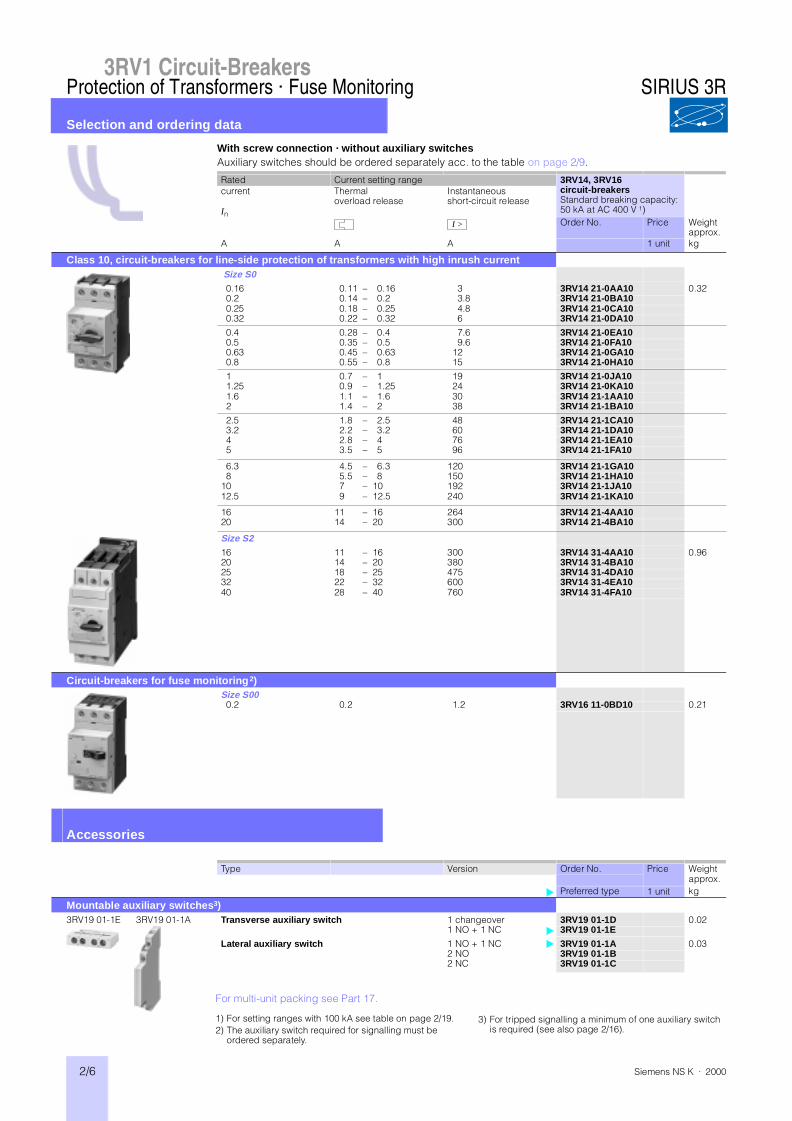
3RV1 Circuit-Breakers
With screw connection · without auxiliary switchesAuxiliary switches should be ordered separately acc. to the table on page 2/9.
Rated Current setting range 3RV14, 3RV16circuit-breakersStandard breaking capacity:50 kA at AC 400 V 1)
current
In
Thermaloverload release
Instantaneousshort-circuit release
Order No. Price Weightapprox.
A A A 1 unit kg
Class 10, circuit-breakers for line-side protection of transformers with high inrush current Size S00.16 0.11 – 0.16 3 3RV14 21-0AA10 0.320.2 0.14 – 0.2 3.8 3RV14 21-0BA100.25 0.18 – 0.25 4.8 3RV14 21-0CA100.32 0.22 – 0.32 6 3RV14 21-0DA10
0.4 0.28 – 0.4 7.6 3RV14 21-0EA100.5 0.35 – 0.5 9.6 3RV14 21-0FA100.63 0.45 – 0.63 12 3RV14 21-0GA100.8 0.55 – 0.8 15 3RV14 21-0HA10
1 0.7 – 1 19 3RV14 21-0JA101.25 0.9 – 1.25 24 3RV14 21-0KA101.6 1.1 – 1.6 30 3RV14 21-1AA102 1.4 – 2 38 3RV14 21-1BA10
2.5 1.8 – 2.5 48 3RV14 21-1CA103.2 2.2 – 3.2 60 3RV14 21-1DA104 2.8 – 4 76 3RV14 21-1EA105 3.5 – 5 96 3RV14 21-1FA10
6.3 4.5 – 6.3 120 3RV14 21-1GA108 5.5 – 8 150 3RV14 21-1HA10
10 7 – 10 192 3RV14 21-1JA1012.5 9 – 12.5 240 3RV14 21-1KA10
16 11 – 16 264 3RV14 21-4AA1020 14 – 20 300 3RV14 21-4BA10
Size S216 11 – 16 300 3RV14 31-4AA10 0.9620 14 – 20 380 3RV14 31-4BA1025 18 – 25 475 3RV14 31-4DA1032 22 – 32 600 3RV14 31-4EA1040 28 – 40 760 3RV14 31-4FA10
Circuit-breakers for fuse monitoring2)Size S000.2 0.2 1.2 3RV16 11-0BD10 0.21
Accessories
Type Version Order No. Price Weightapprox.
Preferred type 1 unit kg
Mountable auxiliary switches3)3RV19 01-1E 3RV19 01-1A Transverse auxiliary switch 1 changeover 3RV19 01-1D 0.02
1 NO + 1 NC 3RV19 01-1E
Lateral auxiliary switch 1 NO + 1 NC 3RV19 01-1A 0.032 NO 3RV19 01-1B2 NC 3RV19 01-1C
I >
3) For tripped signalling a minimum of one auxiliary switch is required (see also page 2/16).
For multi-unit packing see Part 17.
1) For setting ranges with 100 kA see table on page 2/19.2) The auxiliary switch required for signalling must be
ordered separately.
SIRIUS 3R
3RV1 Circuit-Breakers
2/7Siemens NS K · 2000
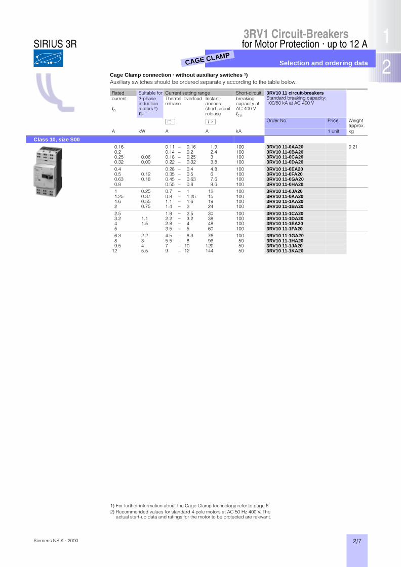
for Motor Protection · up to 12 A
Selection and ordering data
Cage Clamp connection · without auxiliary switches 1)Auxiliary switches should be ordered separately according to the table below.
Rated Suitable for Current setting range Short-circuit 3RV10 11 circuit-breakersStandard breaking capacity:100/50 kA at AC 400 V
current
In
3-phase induction motors 2)Pn
Thermal overload release
Instant-aneous short-circuit release
breaking capacity atAC 400 VIcu
Order No. Price Weightapprox.
A kW A A kA 1 unit kg
Class 10, size S000.16 0.11 – 0.16 1.9 100 3RV10 11-0AA20 0.210.2 0.14 – 0.2 2.4 100 3RV10 11-0BA200.25 0.06 0.18 – 0.25 3 100 3RV10 11-0CA200.32 0.09 0.22 – 0.32 3.8 100 3RV10 11-0DA20
0.4 0.28 – 0.4 4.8 100 3RV10 11-0EA200.5 0.12 0.35 – 0.5 6 100 3RV10 11-0FA200.63 0.18 0.45 – 0.63 7.6 100 3RV10 11-0GA200.8 0.55 – 0.8 9.6 100 3RV10 11-0HA201 0.25 0.7 – 1 12 100 3RV10 11-0JA201.25 0.37 0.9 – 1.25 15 100 3RV10 11-0KA201.6 0.55 1.1 – 1.6 19 100 3RV10 11-1AA202 0.75 1.4 – 2 24 100 3RV10 11-1BA20
2.5 1.8 – 2.5 30 100 3RV10 11-1CA203.2 1.1 2.2 – 3.2 38 100 3RV10 11-1DA204 1.5 2.8 – 4 48 100 3RV10 11-1EA205 3.5 – 5 60 100 3RV10 11-1FA206.3 2.2 4.5 – 6.3 76 100 3RV10 11-1GA208 3 5.5 – 8 96 50 3RV10 11-1HA209.5 4 7 – 10 120 50 3RV10 11-1JA20
12 5.5 9 – 12 144 50 3RV10 11-1KA20
I >
1) For further information about the Cage Clamp technology refer to page 6.2) Recommended values for standard 4-pole motors at AC 50 Hz 400 V. The
actual start-up data and ratings for the motor to be protected are relevant.
CAGE CLAMP
SIRIUS 3R

2/8 Siemens NS K · 2000
for Motor Protection · up to 12 A
Accessories
3RV1 Circuit-Breakers
Type Version Order No. Price Weightapprox.kg
Laterally mountable auxiliary switch with Cage Clamp connection1 lateral auxiliary switch 1 unitper circuit-breaker 1 NO + 1 NC 3RV19 01 -2A 0.03mountable on the left-hand side 1 unit
2 NO 3RV19 01 -2B1 unit
2 NC 3RV19 01 -2C
Adapters and link modules for Cage Clamp connection
3RA1911-2A + 8US1051-5CM47
Link module for Cage Clamp connection1 packg.
for electrical contacting betweencircuit-breaker and contactor(1 packing = 10 units)
Size S00 3RA19 11-2A 0.12
Link module for Cage Clamp connection with mechanical fixing 1 packg.
for mechanical fixing and electrical contacting between circuit-breaker and contactor(1 packing = 10 units)
Size S00 ‡ 3RA19 11-2E 0.03
Adapter for rail mounting 1 packg.for Cage Clamp with 2 mounting rails,one adjustable (1 packing = 5 units)
45 mm wide 3RA19 22-1L 0.26
Busbar adapter 1 unit
45 mm wide, 182 mm long 40 mm wide 8US10 51-5CM47 0.17adapted for Cage Clamp circuit-breakers.An additional standard mounting rail must be used if increased protection is required.
60 mm wide 8US12 51-5CM47
35 mm standard mounting rail, 1 packg.Plastic, including fixing screws(1 packing = 10 units)
45 mm wide 8US19 98-7CA05 0.09
3-phase busbars for Cage Clamp connection3RV1915-1BA 3-phase busbars for
Cage Clamp connection1 unit
incl. 2 holders, for 3 breakers S00‡ 3RV19 15-1BA 0.10modular spacing 45 mm or more.Terminal blocks can be used for feeding in.Rated current (supply side): 16 A
for 4 breakers S00 3RV19 15-1CA 0.13
Screwdriver 3.5 × 0.5 for opening the Cage Clamp terminal1 unit
For all SIRIUS devices with Cage Clamp connection
Length approx. 100 mm 8WA2 804 0.012Length approx. 175 mm 8WA2 803 0.029
3RA1911-2E
CAGE CLAMP
SIRIUS 3R
3RV1 Circuit-Breakers
2/9Siemens NS K · 2000
up to 100 A
Accessories
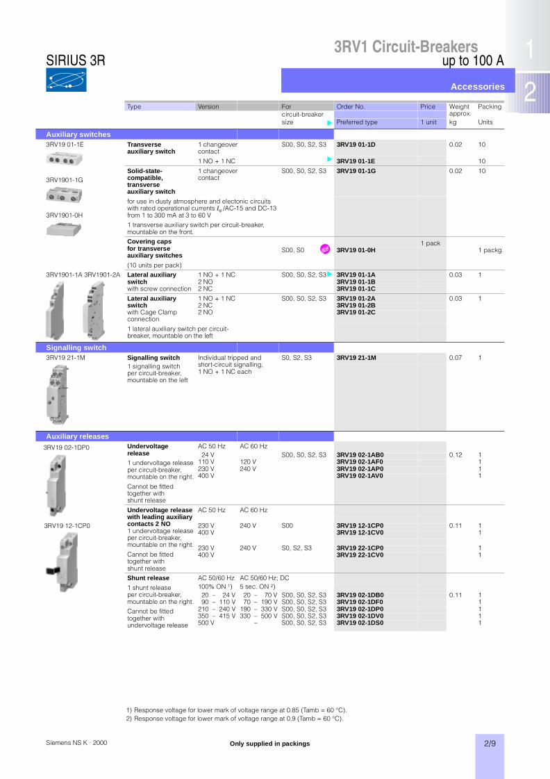
Type Version For Order No. Price Weightapprox.
Packingcircuit-breakersize Preferred type 1 unit kg Units
Auxiliary switches3RV19 01-1E
3RV1901-1G
3RV1901-0H
Transverse auxiliary switch
1 changeover contact
S00, S0, S2, S3 3RV19 01-1D 0.02 10
1 NO + 1 NC 3RV19 01-1E 10
Solid-state-compatible, transverse auxiliary switch
1 changeovercontact
S00, S0, S2, S3 3RV19 01-1G 0.02 10
for use in dusty atmosphere and electonic circuits with rated operational currents Ie /AC-15 and DC-13 from 1 to 300 mA at 3 to 60 V1 transverse auxiliary switch per circuit-breaker, mountable on the front.Covering caps for transverseauxiliary switches
(10 units per pack)
1 packS00, S0 ‡ 3RV19 01-0H 1 packg.
3RV1901-1A 3RV1901-2A Lateral auxiliary switch with screw connection
1 NO + 1 NC S00, S0, S2, S3 3RV19 01-1A 0.03 12 NO 3RV19 01-1B2 NC 3RV19 01-1C
Lateral auxiliary switchwith Cage Clampconnection
1 NO + 1 NC S00, S0, S2, S3 3RV19 01-2A 0.03 12 NC 3RV19 01-2B2 NO 3RV19 01-2C
1 lateral auxiliary switch per circuit-breaker, mountable on the left
Signalling switch3RV19 21-1M Signalling switch Individual tripped and
short-circuit signalling,1 NO + 1 NC each
S0, S2, S3 3RV19 21-1M 0.07 11 signalling switch per circuit-breaker, mountable on the left
Auxiliary releases3RV19 02-1DP0 Undervoltage
release1 undervoltage release per circuit-breaker, mountable on the right.
Cannot be fitted together with shunt release
AC 50 Hz AC 60 Hz24 V S00, S0, S2, S3 3RV19 02-1AB0 0.12 1
110 V 120 V 3RV19 02-1AF0 1230 V 240 V 3RV19 02-1AP0 1400 V 3RV19 02-1AV0 1
Undervoltage release with leading auxiliary contacts 2 NO1 undervoltage release per circuit-breaker, mountable on the right.
Cannot be fitted together with shunt release
AC 50 Hz AC 60 Hz
230 V 240 V S00 3RV19 12-1CP0 0.11 1400 V 3RV19 12-1CV0 1
230 V 240 V S0, S2, S3 3RV19 22-1CP0 1400 V 3RV19 22-1CV0 1
Shunt release
1 shunt release per circuit-breaker, mountable on the right.Cannot be fitted together with undervoltage release
AC 50/60 Hz AC 50/60 Hz; DC100% ON 1) 5 sec. ON 2)20 – 24 V 20 – 70 V S00, S0, S2, S3 3RV19 02-1DB0 0.11 190 – 110 V 70 – 190 V S00, S0, S2, S3 3RV19 02-1DF0 1
210 – 240 V 190 – 330 V S00, S0, S2, S3 3RV19 02-1DP0 1350 – 415 V 330 – 500 V S00, S0, S2, S3 3RV19 02-1DV0 1500 V 33 0– S00, S0, S2, S3 3RV19 02-1DS0 1
3RV19 12-1CP0
Only supplied in packings
1) Response voltage for lower mark of voltage range at 0.85 (Tamb = 60 °C).2) Response voltage for lower mark of voltage range at 0.9 (Tamb = 60 °C).
SIRIUS 3R

2/10 Siemens NS K · 2000
up to 100 A
Accessories
3RV1 Circuit-Breakers
Type Version For Order No. Price Weightapprox.
Packcircuit-breakersize kg Units
Covers3RV1 (size S3) with3RT19 46-4EA1
Terminal cover Additional touch guard 1 unitfor box terminals to be fitted at the box terminals S2 3RT19 36-4EA2 0.01 1
(2 units can be mounted per circuit-breaker)
S3 3RT19 46-4EA2 1
Terminal cover For maintaining the required 1 unitfor cable lug andbusbar connection
voltage clearance and as protection against the equipment being touched if distant box terminals are used (2 units can be mounted per circuit-breaker)
S3 3RT19 46-4EA1 0.03 1
3RV19 08-0P Scale cover For covering the current setting 1 bagsealable scale. Packing unit: Bag with 10
scale covers (Order No. and price per bag)
S00, S0, S2, S3
3RV19 08-0P 1
Door-coupling rotary operating mechanisms3RV19 26-0B The door-coupling rotary operating mechanisms consist of a knob, a coupling driver and a 300 mm long extension shaft (5 mm x
5 mm). The door-coupling rotary operating mechanisms are designed for degree of protection IP 65. The door locking device prevents accidental opening of the cubicle door in the ON position of the circuit-breaker. The OFF position can be locked with up to 3 padlocks.
Door-coupling rotary operating mechanism,black
1 unitExtension shaft 130 mm S0, S2, S3 3RV19 26-0B 0.1 1Extension shaft 330 mm with supporting bracket
S0, S2, S3 3RV19 26-0K 0.3 1
EMERGENCY STOP door-coupling rotary operating mechanism, red/yellow
1 unitExtension shaft 130 mm S0, S2, S3 3RV19 26-0C 0.1 1Extension shaft 330 mm with supporting bracket
S0, S2, S3 3RV19 26-0L 0.3 1
Door-coupling rotary operating mechanisms for arduous conditions1)3RV19 26-1C The door-coupling rotary operating mechanisms consist of a knob, a coupling driver, a 300 mm long extension shaft (6 mm x 6 mm)
and a spacer and two metal brackets, into which the circuit-breaker is inserted. The door-coupling rotary operating mechanisms are designed for degree of protection IP 65. The door locking device reliably prevents accidental opening of the cubicle door in the ON position of the circuit-breaker. The OFF position can be locked with up to 3 padlocks. The door-coupling rotary operating mechanisms thus comply with the requirements of IEC 60 947-2 concerning isolator characteristics.
Door-coupling rotary operating mechanism, grey
1 unitS0 3RV19 26-1B 1.0 1S2 ‡ 3RV19 36-1B 1.1 1S3 3RV19 46-1B 1.6 1
EMERGENCY STOP door-coupling rotary operating mechanism, red/yellow
1 unitS0 3RV19 26-1C 1.0 1S2 ‡ 3RV19 36-1C 1.1 1S3 3RV19 46-1C 1.6 1
Mounting accessories3RB19 00-0B Push-in lugs For screwing the circuit-breaker
onto mounting plates. 2 units required per circuit-breaker.(1 bag = 10 units)
1 bag3RB19 00-0B 0.01 1
3RV19 18-5A with circuit-breaker
Solder pin connection For soldering the main conductor connections of a circuit-breaker to a printed-circuit board. (1 pack = 8 parts for 4 circuit-breakers)
1 packfor main contacts S00 3RV19 18-5A 0.10 1
for main and auxiliary contacts
For soldering the main conductor connections and the auxiliary conductor connections of the transverse auxiliary switch (1 NO + 1 NC) of a circuit-breaker to a printed-circuit board. (1 pack = 8 parts for main conductor connection + 4 parts for auxiliary conductor connection for 4 circuit-breakers)
1 packS00 3RV19 18-5B 0.19 1
3RV19 48-1E Plug-in socket for main contactsNote: Specially equippedcircuit-breakers are required for the plug-in socket2)
Plug-in socket with upper and lower terminal connections (1 set = 1 plug-in socket + 2 plug contact parts)
1 setS3 3RV19 48-1E 1
Plug-in socket with busbarconnection on rear (1 set = 1 plug-in socket + 2 plug contact parts)
1 setS3 3RV19 48-1F 1.40 1
Only supplied in packs
1) Delivery as of March 2000.2) See page 2/3.
SIRIUS 3R
3RV1 Circuit-Breakers
2/11Siemens NS K · 2000
up to 100 A
Accessories
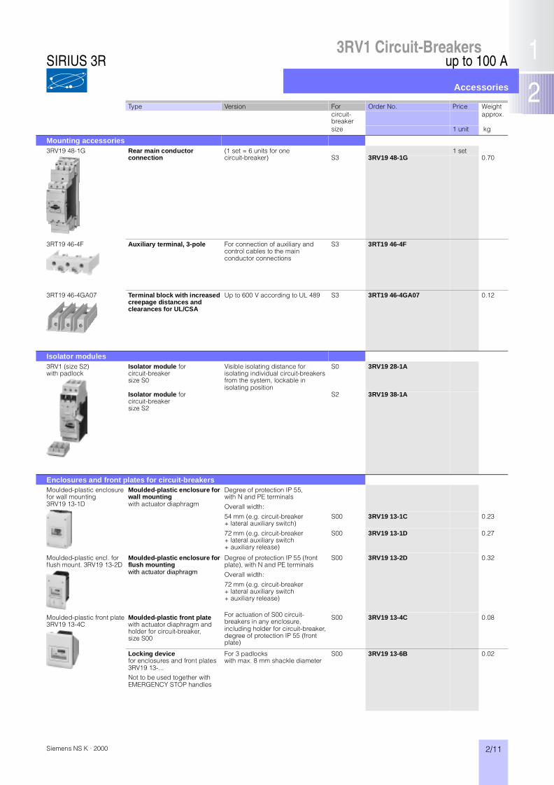
Type Version For Order No. Price Weightcircuit-breaker
approx.
size 1 unit kg
Mounting accessories3RV19 48-1G Rear main conductor
connection(1 set = 6 units for one 1 setcircuit-breaker) S3 3RV19 48-1G 0.70
3RT19 46-4F Auxiliary terminal, 3-pole For connection of auxiliary and control cables to the main conductor connections
S3 3RT19 46-4F
3RT19 46-4GA07 Terminal block with increased creepage distances and clearances for UL/CSA
Up to 600 V according to UL 489 S3 3RT19 46-4GA07 0.12
Isolator modules3RV1 (size S2)with padlock
Isolator module forcircuit-breakersize S0
Visible isolating distance for isolating individual circuit-breakers from the system, lockable in isolating position
S0 3RV19 28-1A
Isolator module forcircuit-breakersize S2
S2 3RV19 38-1A
Enclosures and front plates for circuit-breakersMoulded-plastic enclosure for wall mounting3RV19 13-1D
Moulded-plastic enclosure for wall mountingwith actuator diaphragm
Degree of protection IP 55, with N and PE terminals
Overall width:
54 mm (e.g. circuit-breaker + lateral auxiliary switch)
S00 3RV19 13-1C 0.23
72 mm (e.g. circuit-breaker + lateral auxiliary switch + auxiliary release)
S00 3RV19 13-1D 0.27
Moulded-plastic encl. for flush mount. 3RV19 13-2D
Moulded-plastic enclosure for flush mountingwith actuator diaphragm
Degree of protection IP 55 (front plate), with N and PE terminals
Overall width:
72 mm (e.g. circuit-breaker + lateral auxiliary switch + auxiliary release)
S00 3RV19 13-2D 0.32
Moulded-plastic front plate3RV19 13-4C
Moulded-plastic front platewith actuator diaphragm and holder for circuit-breaker,size S00
For actuation of S00 circuit-breakers in any enclosure, including holder for circuit-breaker, degree of protection IP 55 (front plate)
S00 3RV19 13-4C 0.08
Locking devicefor enclosures and front plates 3RV19 13-... Not to be used together with EMERGENCY STOP handles
For 3 padlockswith max. 8 mm shackle diameter
S00 3RV19 13-6B 0.02
SIRIUS 3R
up to 100 A3RV1 Circuit-Breakers
Accessories
2/12 Siemens NS K · 2000
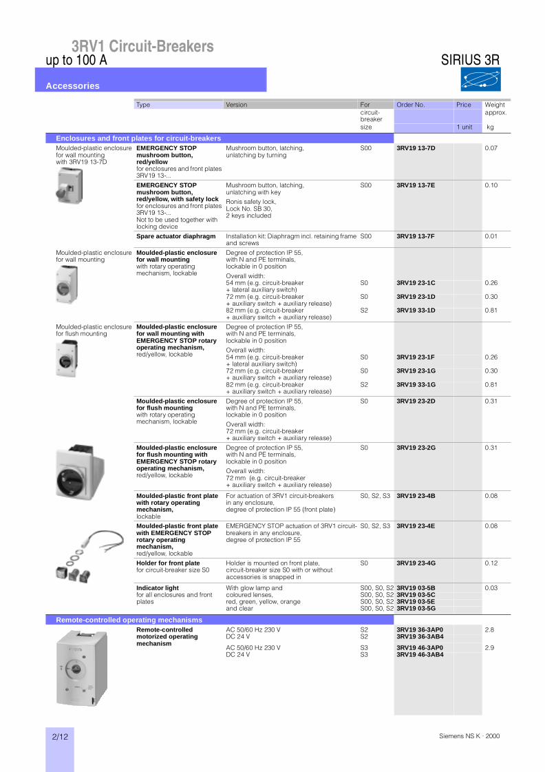
Type Version For Order No. Price Weightcircuit-breaker
approx.
size 1 unit kg
Enclosures and front plates for circuit-breakersMoulded-plastic enclosure for wall mountingwith 3RV19 13-7D
EMERGENCY STOP mushroom button, red/yellowfor enclosures and front plates 3RV19 13-...
Mushroom button, latching, unlatching by turning
S00 3RV19 13-7D 0.07
EMERGENCY STOP mushroom button, red/yellow, with safety lockfor enclosures and front plates 3RV19 13-...Not to be used together with locking device
Mushroom button, latching,unlatching with keyRonis safety lock,Lock No. SB 30, 2 keys included
S00 3RV19 13-7E 0.10
Spare actuator diaphragm Installation kit: Diaphragm incl. retaining frame and screws
S00 3RV19 13-7F 0.01
Moulded-plastic enclosure for wall mounting
Moulded-plastic enclosure for wall mountingwith rotary operating mechanism, lockable
Degree of protection IP 55, with N and PE terminals, lockable in 0 position
Overall width:54 mm (e.g. circuit-breaker + lateral auxiliary switch)
S0 3RV19 23-1C 0.26
72 mm (e.g. circuit-breaker+ auxiliary switch + auxiliary release)
S0 3RV19 23-1D 0.30
82 mm (e.g. circuit-breaker + auxiliary switch + auxiliary release)
S2 3RV19 33-1D 0.81
Moulded-plastic enclosure for flush mounting
Moulded-plastic enclosure for wall mounting with EMERGENCY STOP rotary operating mechanism,red/yellow, lockable
Degree of protection IP 55, with N and PE terminals, lockable in 0 positionOverall width:54 mm (e.g. circuit-breaker + lateral auxiliary switch)
S0 3RV19 23-1F 0.26
72 mm (e.g. circuit-breaker + auxiliary switch + auxiliary release)
S0 3RV19 23-1G 0.30
82 mm (e.g. circuit-breaker + auxiliary switch + auxiliary release)
S2 3RV19 33-1G 0.81
Moulded-plastic enclosure for flush mountingwith rotary operating mechanism, lockable
Degree of protection IP 55, with N and PE terminals, lockable in 0 position
Overall width: 72 mm (e.g. circuit-breaker + auxiliary switch + auxiliary release)
S0 3RV19 23-2D 0.31
Moulded-plastic enclosure for flush mounting with EMERGENCY STOP rotary operating mechanism,red/yellow, lockable
Degree of protection IP 55, with N and PE terminals, lockable in 0 positionOverall width: 72 mm (e.g. circuit-breaker + auxiliary switch + auxiliary release)
S0 3RV19 23-2G 0.31
Moulded-plastic front plate with rotary operating mechanism, lockable
For actuation of 3RV1 circuit-breakers in any enclosure, degree of protection IP 55 (front plate)
S0, S2, S3 3RV19 23-4B 0.08
Moulded-plastic front plate with EMERGENCY STOP rotary operating mechanism,red/yellow, lockable
EMERGENCY STOP actuation of 3RV1 circuit-breakers in any enclosure, degree of protection IP 55
S0, S2, S3 3RV19 23-4E 0.08
Holder for front platefor circuit-breaker size S0
Holder is mounted on front plate, circuit-breaker size S0 with or without accessories is snapped in
S0 3RV19 23-4G 0.12
Indicator light for all enclosures and front plates
With glow lamp and S00, S0, S2 3RV19 03-5B 0.03coloured lenses, S00, S0, S2 3RV19 03-5Cred, green, yellow, orange S00, S0, S2 3RV19 03-5Eand clear S00, S0, S2 3RV19 03-5G
Remote-controlled operating mechanismsRemote-controlled motorized operating mechanism
AC 50/60 Hz 230 V S2 3RV19 36-3AP0 2.8DC 24 V S2 3RV19 36-3AB4
AC 50/60 Hz 230 V S3 3RV19 46-3AP0 2.9DC 24 V S3 3RV19 46-3AB4
SIRIUS 3R

3RV1 Circuit-Breakers
2/13Siemens NS K · 2000
up to 100 A
Accessories
Type Version For Order No. Price Weightcircuit-breaker
approx.
size 1 unit kg
Busbar adapters for circuit-breakersFor mechanical fixing and electrical contacting onto busbar systems. For circuit-breakers with screw connection. For systems with 3 busbars and the following busbar dimensions:• Width for 40 mm system: 12 mm to 15 mm• Width for 60 mm system: 12 mm to 30 mm• Thickness: 5 mm and 10 mm, with rounded edges according to DIN 46 433
For other busbar adapters, busbar copper, line and load-side terminals and accessories see Part 13.For starter combinations on busbar adapters see also Part 5, "Fuseless Load Feeders".
8US 10 61-5DJ07 40 mm system (busbar centre-line spacing)
• Busbar adapter40 mm system
Length 121 mm Width 45 mm S00, S0 8US10 51-5DJ07 0.09Length 121 mm Width 55 mm S00, S0 8US10 61-5DJ07 0.10Length 139 mm Width 55 mm S2 8US10 61-5FK08 0.23Length 182 mm Width 70 mm S3 8US11 11-4SM00 0.45
• Lateral module for busbar adapter 40 mm system
For widening the adapters, can be snapped onto both endsLength 139 mm Width 13.5 mm S2 8US19 98-2BK00 0.04Length 182 mm Width 13.5 mm S3 8US19 98-2BM00 0.04
• Busbar holderfor 3 copper busbars40 mm system
1 set = 2 units S00 - S3 3VX4 280-2R 0.05
8US12 51-5MD07 • Moulded-plastic coversfor line-side terminals40 mm system
Fitted onto the 3VX4 280-2R busbar holder, covers 3 terminals up to 35 mm²
S00 - S3 3VX4 280-2S 0.04
60 mm system (busbar centre-line spacing)• Busbar adapter
60 mm systemLength 182 mm Width 45 mm S00, S0 8US12 51-5DM07 0.18Length 182 mm Width 55 mm S2 8US12 61-5FM08 0.23Length 182 mm Width 70 mm S3 8US11 11-4SM00 0.45
• Lateral module for busbar adapter 60 mm system
For widening the adapters, can be snapped onto both endsLength 182 mm Width 13.5 mm S00 - S3 8US19 98-2BM00 0.03
• Busbar holderfor 3 copper busbars60 mm system
1 unit S00 - S3 8US19 23-2AA00 0.16
Moulded-plastic cover profiles for busbars• for 1 busbar 1)
12 × 5 mmTouch guard 1000 mm long S00 - S3 8GR5 010 0.05separable, snaps on
• for 3 busbars 1)12 × 5 mm or 10 mm
Touch guard 54 mm long S00 - S3 8US19 02-3AA00 0.01and empty-space cover
430 mm long S00 - S3 8US19 02-4AA00 On req.
• for 1 busbar30 × 5 mm
Touch guard 1000 mm long S00 - S3 8US19 22-2AA00 0.04separable, snaps on
• for 1 busbar30 × 10 mm
Touch guard 1000 mm long S00 - S3 8US19 22-2BA00 0.084separable, snaps on
Type Order No. Price Weightapprox.
1 pack kg
Link modulesLink module, Cage Clamp 3RA19 11-2A 0.12for electrical contacting between circuit-breaker and contactor. Specifically for Cage Clamp connections.Size S00(1 pack = 10 units)(Busbar adapter not included in scope of supply)
Link module, Cage Clamp, for mechanical fixing ‡ 3RA19 11-2E 0.03
For mechanical fixing and electrical contacting between circuit-breaker and contactor.Size S00(1 pack = 10 units)
1) For 40 mm system (busbar centre-line spacing 40 mm).
SIRIUS 3R
2/14 Siemens NS K · 2000
up to 100 A
Accessories
3RV1 Circuit-Breakers
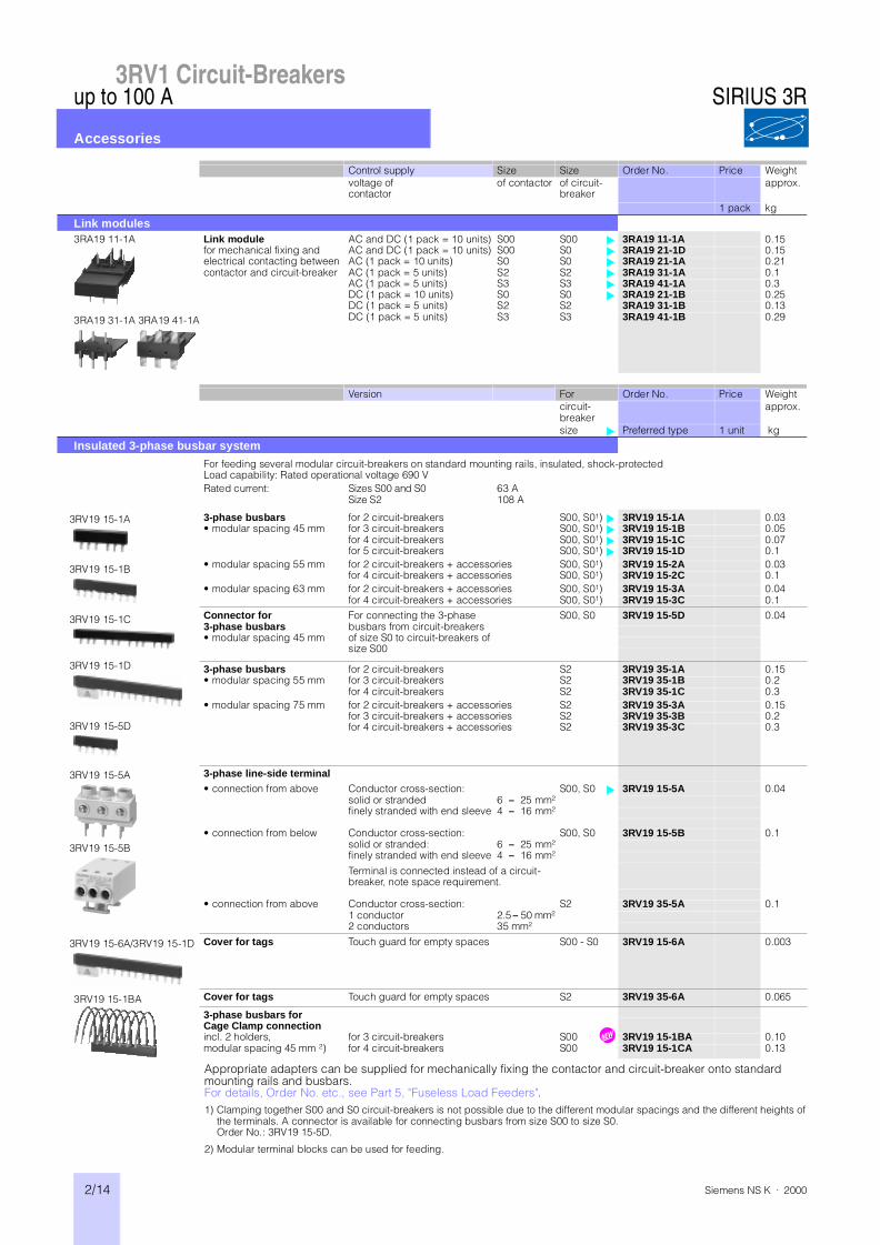
Control supply Size Size Order No. Price Weightvoltage ofcontactor
of contactor of circuit-breaker
approx.
1 pack kg
Link modules3RA19 11-1A
3RA19 31-1A 3RA19 41-1A
Link module AC and DC (1 pack = 10 units) S00 S00 3RA19 11-1A 0.15for mechanical fixing and electrical contacting between contactor and circuit-breaker
AC and DC (1 pack = 10 units) S00 S0 3RA19 21-1D 0.15AC (1 pack = 10 units) S0 S0 3RA19 21-1A 0.21AC (1 pack = 5 units) S2 S2 3RA19 31-1A 0.1AC (1 pack = 5 units) S3 S3 3RA19 41-1A 0.3DC (1 pack = 10 units) S0 S0 3RA19 21-1B 0.25DC (1 pack = 5 units) S2 S2 3RA19 31-1B 0.13DC (1 pack = 5 units) S3 S3 3RA19 41-1B 0.29
Version For Order No. Price Weightcircuit-breaker
approx.
size Preferred type 1 unit kg
Insulated 3-phase busbar system
For feeding several modular circuit-breakers on standard mounting rails, insulated, shock-protectedLoad capability: Rated operational voltage 690 VRated current: Sizes S00 and S0
Size S263 A108 A
3RV19 15-1A
3RV19 15-1B
3RV19 15-1C
3RV19 15-1D
3RV19 15-5D
3-phase busbars for 2 circuit-breakers S00, S01) 3RV19 15-1A 0.03• modular spacing 45 mm for 3 circuit-breakers S00, S01) 3RV19 15-1B 0.05
for 4 circuit-breakers S00, S01) 3RV19 15-1C 0.07for 5 circuit-breakers S00, S01) 3RV19 15-1D 0.1
• modular spacing 55 mm for 2 circuit-breakers + accessories S00, S01) 3RV19 15-2A 0.03for 4 circuit-breakers + accessories S00, S01) 3RV19 15-2C 0.1
• modular spacing 63 mm for 2 circuit-breakers + accessories S00, S01) 3RV19 15-3A 0.04for 4 circuit-breakers + accessories S00, S01) 3RV19 15-3C 0.1
Connector for 3-phase busbars• modular spacing 45 mm
For connecting the 3-phasebusbars from circuit-breakers of size S0 to circuit-breakers of size S00
S00, S0 3RV19 15-5D 0.04
3-phase busbars for 2 circuit-breakers S2 3RV19 35-1A 0.15• modular spacing 55 mm for 3 circuit-breakers S2 3RV19 35-1B 0.2
for 4 circuit-breakers S2 3RV19 35-1C 0.3• modular spacing 75 mm for 2 circuit-breakers + accessories S2 3RV19 35-3A 0.15
for 3 circuit-breakers + accessories S2 3RV19 35-3B 0.2for 4 circuit-breakers + accessories S2 3RV19 35-3C 0.3
3RV19 15-5A
3RV19 15-5B
3-phase line-side terminal• connection from above Conductor cross-section: S00, S0 3RV19 15-5A 0.04
solid or stranded 6 – 25 mm²finely stranded with end sleeve 4 – 16 mm²
• connection from below Conductor cross-section: S00, S0 3RV19 15-5B 0.1solid or stranded: 6 – 25 mm²finely stranded with end sleeve 4 – 16 mm²
Terminal is connected instead of a circuit-breaker, note space requirement.
• connection from above Conductor cross-section: S2 3RV19 35-5A 0.11 conductor 2.5 – 50 mm²2 conductors 35 mm²
3RV19 15-6A/3RV19 15-1D Cover for tags Touch guard for empty spaces S00 - S0 3RV19 15-6A 0.003
3RV19 15-1BA Cover for tags Touch guard for empty spaces S2 3RV19 35-6A 0.065
3-phase busbars for Cage Clamp connectionincl. 2 holders, for 3 circuit-breakers S00 ‡ 3RV19 15-1BA 0.10modular spacing 45 mm 2) for 4 circuit-breakers S00 3RV19 15-1CA 0.13
Appropriate adapters can be supplied for mechanically fixing the contactor and circuit-breaker onto standard mounting rails and busbars.For details, Order No. etc., see Part 5, "Fuseless Load Feeders".1) Clamping together S00 and S0 circuit-breakers is not possible due to the different modular spacings and the different heights of
the terminals. A connector is available for connecting busbars from size S00 to size S0.Order No.: 3RV19 15-5D.
2) Modular terminal blocks can be used for feeding.
SIRIUS 3R
3RV1 Circuit-Breakers
2/15Siemens NS K · 2000
up to 100 A
Technical data
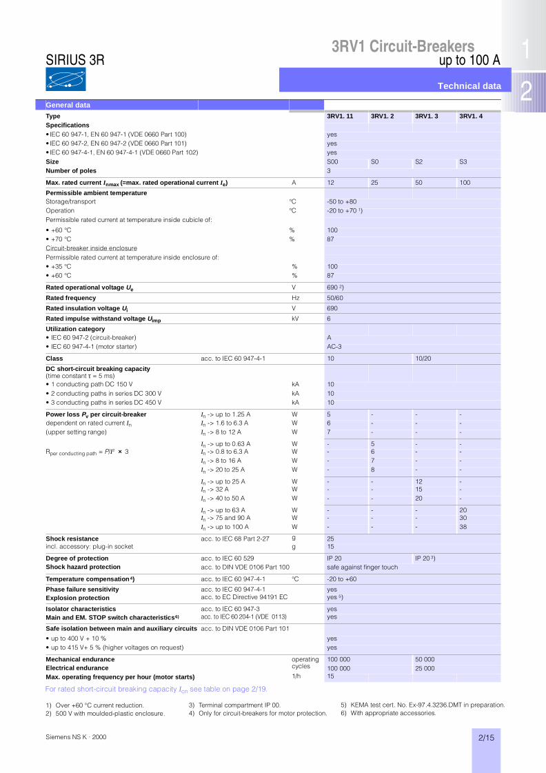
For rated short-circuit breaking capacity Icn see table on page 2/19.
General dataType 3RV1. 11 3RV1. 2 3RV1. 3 3RV1. 4Specifications• IEC 60 947-1, EN 60 947-1 (VDE 0660 Part 100) yes• IEC 60 947-2, EN 60 947-2 (VDE 0660 Part 101) yes• IEC 60 947-4-1, EN 60 947-4-1 (VDE 0660 Part 102) yesSize S00 S0 S2 S3Number of poles 3
Max. rated current Inmax (=max. rated operational current Ie) A 12 25 50 100
Permissible ambient temperatureStorage/transport °C -50 to +80Operation °C -20 to +70 1)Permissible rated current at temperature inside cubicle of:
• +60 °C % 100• +70 °C % 87Circuit-breaker inside enclosurePermissible rated current at temperature inside enclosure of: • +35 °C % 100• +60 °C % 87
Rated operational voltage Ue V 690 2)
Rated frequency Hz 50/60
Rated insulation voltage Ui V 690
Rated impulse withstand voltage Uimp kV 6
Utilization category• IEC 60 947-2 (circuit-breaker) A• IEC 60 947-4-1 (motor starter) AC-3
Class acc. to IEC 60 947-4-1 10 10/20
DC short-circuit breaking capacity (time constant τ = 5 ms)• 1 conducting path DC 150 V kA 10• 2 conducting paths in series DC 300 V kA 10• 3 conducting paths in series DC 450 V kA 10
Power loss Pv per circuit-breaker In -> up to 1.25 A W 5 - - -dependent on rated current In In -> 1.6 to 6.3 A W 6 - - -(upper setting range) In -> 8 to 12 A W 7 - - -
In -> up to 0.63 A W - 5 - -Rper conducting path = P/I² × 3 In -> 0.8 to 6.3 A W - 6 - -
In -> 8 to 16 A W - 7 - -In -> 20 to 25 A W - 8 - -
In -> up to 25 A W - - 12 -In -> 32 A W - - 15 -In -> 40 to 50 A W - - 20 -
In -> up to 63 A W - - - 20In -> 75 and 90 A W - - - 30In -> up to 100 A W - - - 38
Shock resistance acc. to IEC 68 Part 2-27 g 25incl. accessory: plug-in socket g 15
Degree of protection acc. to IEC 60 529 IP 20 IP 20 3)Shock hazard protection acc. to DIN VDE 0106 Part 100 safe against finger touch
Temperature compensation 4) acc. to IEC 60 947-4-1 °C -20 to +60
Phase failure sensitivity acc. to IEC 60 947-4-1 yesExplosion protection acc. to EC Directive 94191 EC yes 5)
Isolator characteristics acc. to IEC 60 947-3 yesMain and EM. STOP switch characteristics6) acc. to IEC 60 204-1 (VDE 0113) yes
Safe isolation between main and auxiliary circuits acc. to DIN VDE 0106 Part 101
• up to 400 V + 10 % yes• up to 415 V+ 5 % (higher voltages on request) yes
Mechanical endurance operating cycles
100 000 50 000Electrical endurance 100 000 25 000Max. operating frequency per hour (motor starts) 1/h 15
1) Over +60 °C current reduction.2) 500 V with moulded-plastic enclosure.
5) KEMA test cert. No. Ex-97.4.3236.DMT in preparation.6) With appropriate accessories.
3) Terminal compartment IP 00.4) Only for circuit-breakers for motor protection.
SIRIUS 3R

2/16 Siemens NS K · 2000
up to 100 A
Technical data
3RV1 Circuit-Breakers
Conductor cross-sections for main circuit1)Type 3RV1. 11 3RV1. 2 3RV1. 3 3RV1. 4
Terminal type Screw-type Box terminalTerminal screw Pozidriv size 2 Pozidriv size 2 Allen screwTightening torque Nm 0.8 to 1.2 2 to 2.5 3 to 4.5 4 to 6
Minimum/maximum conductor cross-sectionsfinely stranded with end sleeve– 1 conductor mm² 0.5/2.5 1/6 0.75/25 2.5/50 2)– 2 conductors mm² 0.5/2.5 1/2.5 or 2.5/6 0.75/16 2.5/35 2)solid or stranded– 1 conductor mm² 0.5/4 1/6 (max. 10) 0.75/35 2.5/70 2)– 2 conductors mm² 0.75/2.5 (max. 4) 1/2.5 or 2.5/6 0.75/25 2.5/50 2)ribbon conductor – – yes yesconductor bar – – – yessolid or stranded AWG 2 x (18 to 14) 2 x (14 to 10) 2 x (18 to 2) –stranded AWG – – – 2 x (10 to 1/0)
Terminal type Cage Clamp 3)
mm² 2 × (0.5 to 2.5) –AWG 2 × (18 to 14)
Permissible mounting position any acc. to IEC 60 447 start command “I”right-hand side or top
Auxiliary switches
Front transverse auxiliary switch with 1 changeover contact Switching capacity for different voltages
Rated operational voltage Ue AC AC V 24 230 400 690Rated operational current Ie/AC-15 A 4 3 1.5 0.5Rated operational current Ie/AC-12 Ith A 10 10 10 10
Rated operational voltage Ue DC L/R 200 ms DC V 24 110 220Rated operational current Ie/DC-13 A 1 0.22 0.1
Front transverse auxiliary switch with 1 NO + 1 NC
Rated operational voltage Ue AC AC V 24 230Rated operational current Ie/AC-15 A 2 0.5Rated operational current Ie/AC-12 Ith A 2.5 2.5
Rated operational voltage Ue DC L/R 200 ms DC V 24 48 60Rated operational current Ie/DC-13 A 1 0.3 0.15
Lateral auxiliary switch with 1 NO + 1 NC, 2 NO, 2 NC and signalling switch
Rated operational voltage Ue AC AC V 24 230 400 690Rated operational current Ie/AC-15 A 6 6 3 1Rated operational current Ie/AC-12 Ith A 10 10 10 10
Rated operational voltage Ue DC L/R 200 ms DC V 24 110 220 440Rated operational current Ie A 2 0.5 0.25 0.1
Auxiliary releases
Undervoltage release
Power consumption during pick-up VA/W 20.2/13uninterrupted duty VA/W 7.2/2.4
Response voltage trip V 0.7 to 0.35 × Us pick-up V 0.85 to 1.1 × Us
Max. opening time(for rated control supply voltage Us see selection and ordering data)
ms 20
Shunt releasehunt release
Power consumption during pick-up: AC voltages VA 20.2/13DC voltages W 13 to 80
Response voltage acc. to IEC 60 947-1 trip V 0.7 to 1.1 × UsPermissible command durationMax. opening time(for rated control supply voltage Us see selection and ordering data)
SIRIUS 3R
1) For details see technical data of contactors, Part 3.2) After removing the box terminals, connection with cable lugs and busbars is also possible.3) For further information about the Cage Clamp technology refer to page 6.4) Prospective short-circuit current < 0.4 kA.

3RV1 Circuit-Breakers
2/17Siemens NS K · 2000
up to 100 A
Technical data
Short-circuit protection for auxiliary and control circuits
Fuses utilization category gL/gG A 10Miniature circuit-breakers C characteristic A 6 4)
Conductor cross-sections for auxiliary and control circuits
Terminal type Screw-typeTerminal screw Pozidriv size 2
Minimum/maximum conductor cross-sectionsfinely stranded with end sleeve– 1 conductor mm² 0.5/2.5– 2 conductors mm² 0.5/2.5solid or stranded– 1 conductor mm² 0.5/4– 2 conductors mm² 0.75/2.5 (4 1))solid or stranded AWG 2 × (18 to 14)
Terminal type Cage Clampmm² 2 × (0.5 to 2.5)
Remote-controlled operating mechanisms
Max. power consumption at Us DC 24 V W 48AC 230 V VA 170
Operating range V 0.85 to 1.1 × UsMinimum command duration at Us s 0.1Maximum command duration s unlimited (uninterrupted operation)Maximum make-/break-time remote-controlled s 2Ready to reclose after approx. s 2.5Operating frequency h-1 25Internal back-up fuse AC 230 V A 0.8
DC 24 V A 1.6
Terminal type of control leads connector with screw connection
Shock resistance acc. to IEC 60 068, Part 2-27 g/ms 25/11
1) Maximum possible.
SIRIUS 3R
2/18 Siemens NS K · 2000
up to 100 A
Technical data
3RV1 Circuit-Breakers
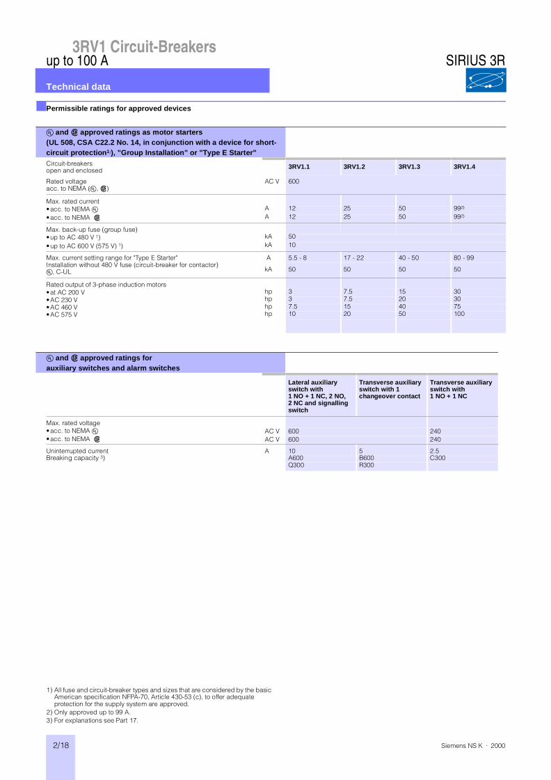
■Permissible ratings for approved devices
E and B approved ratings as motor starters(UL 508, CSA C22.2 No. 14, in conjunction with a device for short-circuit protection1)), "Group Installation" or "Type E Starter"Circuit-breakersopen and enclosed 3RV1.1 3RV1.2 3RV1.3 3RV1.4
Rated voltageacc. to NEMA (E, B)
AC V 600
Max. rated current•acc. to NEMA E A 12 25 50 992)
•acc. to NEMA B A 12 25 50 992)
Max. back-up fuse (group fuse)•up to AC 480 V 1) kA 50•up to AC 600 V (575 V) 1) kA 10
Max. current setting range for "Type E Starter"Installation without 480 V fuse (circuit-breaker for contactor)E, C-UL
A 5.5 - 8 17 - 22 40 - 50 80 - 99
kA 50 50 50 50
Rated output of 3-phase induction motors•at AC 200 V hp 3 7.5 15 30•AC 230 V hp 3 7.5 20 30•AC 460 V hp 7.5 15 40 75•AC 575 V hp 10 20 50 100
E and B approved ratings for auxiliary switches and alarm switches
Lateral auxiliary switch with 1 NO + 1 NC, 2 NO,2 NC and signalling switch
Transverse auxiliary switch with 1changeover contact
Transverse auxiliary switch with1 NO + 1 NC
Max. rated voltage•acc. to NEMA E AC V 600 240•acc. to NEMA B AC V 600 240
Uninterrupted current A 10 5 2.5Breaking capacity 3) A600 B600 C300
Q300 R300
1) All fuse and circuit-breaker types and sizes that are considered by the basic American specification NFPA-70, Article 430-53 (c), to offer adequate protection for the supply system are approved.
2) Only approved up to 99 A.3) For explanations see Part 17.
SIRIUS 3R

3RV1 Circuit-Breakers
2/19Siemens NS K · 2000
up to 100 A
Technical data
■Rated short-circuit breaking capacity Icn ■Fuseless construction
This table shows the rated ulti-mate short-circuit breaking capacity Icu and the rated ser-vice short-circuit breaking capacity Ics of the 3RV1 circuit-breakers with different opera-tional voltages as a function of the rated current In of the cir-cuit-breakers.
The circuit-breakers can be fed at the top or bottom supply
terminals without any reduction of the rated data.
In the coloured areas, Icu is 100 kA or in certain cases 50 kA. The circuit-breakers are therefore short-circuit-proof in these areas.
If the short-circuit current exceeds the rated short-circuit breaking capacity of the circuit-breaker specified in the tables at the installation point, a back-up fuse is to be used.
Alternatively, a circuit-breaker with a limiter function can be connected upstream (see page 2/20).
The maximum rated current for the back-up fuse is specified in the tables. These fuses are only suitable for the short-circuit-currents as indicated on the fuses.
Circuit-breaker/contactor com-binations for short-circuit cur-rents of up to 50 kA can be ordered in the form of fuseless load feeders in accordance with Part 5.
Circuit-breaker
Ratedcurrent In
up to AC 240 V 2) up to AC 400 V 2)/415 V 3) up to AC 440 V 2)/460 V 3) up to AC 500 V 2)/525 V 3) up to AC 690 V 2)
Icu Ics max. Icu Ics max. Icu Ics max. Icu Ics max. Icu Ics max.fuse fuse fuse fuse fuse
(gL/gG) (gL/gG) (gL/gG) (gL/gG) (gL/gG)
Type A kA kA A kA kA A kA kA A kA kA A kA kA A
3RV1011Size S00
0.16 to 0.8 100 100 100 100 100 100 100 100 100 1001 100 100 100 100 100 100 100 100 100 1001.25 100 100 100 100 100 100 100 100 2 2 201.6 100 100 100 100 100 100 100 100 2 2 202 100 100 100 100 100 100 10 10 35 2 2 352.5 100 100 100 100 100 100 10 10 35 2 2 353.2 100 100 100 100 10 10 40 3 3 40 2 2 404 100 100 100 100 10 10 40 3 3 40 2 2 405 100 100 100 100 10 10 50 3 3 50 2 2 506.3 100 100 100 100 10 10 50 3 3 50 2 2 508 100 100 50 12.5 80 1) 10 10 63 3 3 63 2 2 63
10 100 100 50 12.5 80 1) 10 10 63 3 3 63 2 2 6312 100 100 50 12.5 80 1) 10 10 80 3 3 80 2 2 80
3RV1.2Size S0
0.16 to 1.25 100 100 100 100 100 100 100 100 100 1001.6 100 100 100 100 100 100 100 100 100 1002 100 100 100 100 100 100 100 100 8 8 252.5 100 100 100 100 100 100 100 100 8 8 253.2 100 100 100 100 100 100 100 100 8 8 324 100 100 100 100 100 100 100 100 6 3 325 100 100 100 100 100 100 100 100 6 3 326.3 100 100 100 100 100 100 100 100 6 3 508 100 100 100 100 50 25 63 1) 42 21 63 6 3 50
10 100 100 100 100 50 25 80 1) 42 21 63 6 3 5012.5 100 100 100 100 50 25 80 1) 42 21 80 6 3 6316 100 100 50 25 100 1) 20 10 80 10 5 80 4 2 6320 100 100 50 25 125 1) 20 10 80 10 5 80 4 2 6322 100 100 50 25 125 1) 20 10 100 10 5 80 4 2 6325 100 100 50 25 125 1) 20 10 100 10 5 80 4 2 63
3RV1.3Size S2
16 100 100 50 25 100 1) 50 25 100 1) 12 6 63 5 3 6320 100 100 50 25 125 1) 50 25 100 1) 12 6 80 5 3 63
Standard 25 100 100 50 25 125 1) 30 15 100 12 6 80 5 3 63breaking 32 100 100 50 25 125 1) 30 15 125 10 5 100 4 2 63capacity 40 100 100 50 25 160 1) 30 15 125 10 5 100 4 2 63
45 100 100 50 25 160 1) 30 15 125 10 5 100 4 2 6350 100 100 50 25 160 1) 30 15 125 10 5 100 4 2 80
3RV1.4Size S3
40 100 100 50 25 125 1) 40 20 125 12 6 100 6 3 6350 100 100 50 25 125 1) 40 20 125 12 6 100 6 3 80
Standard 63 100 100 50 25 160 1) 40 20 160 12 6 100 6 3 80breaking 75 100 100 50 25 160 1) 40 20 160 8 4 125 5 3 100capacity 90 100 100 50 25 160 1) 40 20 160 8 4 125 5 3 125
100 100 100 50 25 160 1) 40 20 160 8 4 125 5 3 125
3RV1.4Size S3
16 100 100 100 50 50 25 100 1) 30 15 80 12 7 6320 100 100 100 50 50 25 100 1) 30 15 80 12 7 63
Increased 25 100 100 100 50 50 25 100 1) 30 15 80 12 7 63breaking 32 100 100 100 50 50 25 125 1) 22 11 100 12 7 63capacity 40 100 100 100 50 50 25 160 1) 18 9 160 12 6 80
50 100 100 100 50 50 25 160 1) 15 7.5 160 10 5 10063 100 100 100 50 50 25 200 1) 15 7.5 160 7.5 4 10075 100 100 100 50 50 25 200 1) 10 5 160 6 3 12590 100 100 100 50 50 25 200 1) 10 5 160 6 3 160
100 100 100 100 50 50 25 200 1) 10 5 160 6 3 160
Short-circuit-proof up to 50 or 100 kA.No back-up fuse required.
1) Back-up fuse required only if short-circuit current at installation point > 50 kA.2) 10 % overvoltage.3) 5 % overvoltage.
SIRIUS 3R

2/20 Siemens NS K · 2000
up to 100 A
Technical data
3RV1 Circuit-Breakers
■Limiter function with standard devices for AC 500 and AC 690 V
The table shows the rated ulti-mate short-circuit breaking capacity Icu and the rated ser-vice short-circuit breaking capacity Ics with a standard cir-cuit-breaker that fulfils the lim-iter function connected upstream for voltages of AC 500 V and AC 690 V.
The upstream standard circuit-breaker with limiter function enables the short-circuit break-ing capacity to be significantly increased. The upstream cir-cuit-breaker must be set to the maximum value in order to fulfil the limiter function.
The circuit-breaker which is connected downstream must be set to the rated current of the load. If different circuit-breakers are combined, the clearances from earthed parts and the clearances between the individual circuit-breakers must be maintained (see Dimensions).
In addition, short-circuit-proof wiring between the circuit-breakers must be guaranteed. The circuit-breakers are not allowed to be mounted side by side in a modular arrangement.
Standard circuit-breaker Standard circuit-breaker up to AC 500 V / 525 V up to AC 690 Vwith limiter function 1)Type Rated current In Icu Ics Icu IcsRated current In Type A kA kA kA kA
3RV10 2 2) 3RV1. 2 up to 1Size S0 Size S0 1.25In = 25 A 1.6
2 50 252.5 50 253.2 50 254 50 255 50 256.3 50 258 100 50 20 10
10 100 50 20 1012.5 100 50 20 1016 100 50 20 1020 100 50 20 1022 100 50 20 1025 100 50 20 10
3RV10 3 3RV1. 3 16 100 50 50 25Size S2 Size S2 20 100 50 50 25In = 50 A 25 100 50 50 25
32 100 50 50 2540 100 50 50 2550 100 50 50 25
3RV10 4 3RV1. 4 32 100 50 50 25Size S3 Size S3 40 100 50 50 25In = 50 A 50 100 50 50 25
3RV10 4 3RV1. 4 50 100 50 50 25Size S3 Size S3 63 100 50 50 25In = 100 A 75 100 50 50 25
90 100 50 50 25100 100 50 50 25
Short-circuit-proof up to 100 kA.No upstream circuit-breaker required; short-circuit-proof up to 100 kA.
1) A 3RV13 starting circuit-breaker of the same size and with the same rated current can be used alternatively.
2) An insulated plate must be used for size S0 and AC 690 V.
SIRIUS 3R
3RV1 Circuit-Breakers
2/21Siemens NS K · 2000
up to 100 A
Description
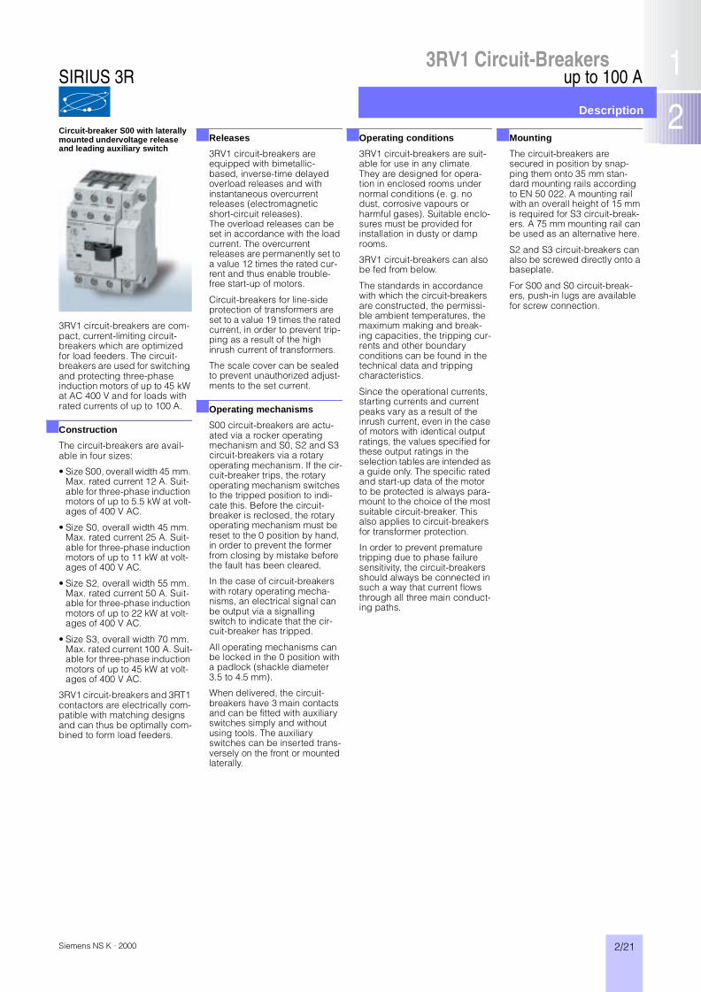
Circuit-breaker S00 with laterally mounted undervoltage release and leading auxiliary switch
■Releases
3RV1 circuit-breakers are equipped with bimetallic-based, inverse-time delayed overload releases and with instantaneous overcurrent releases (electromagnetic short-circuit releases).The overload releases can be set in accordance with the load current. The overcurrent releases are permanently set to a value 12 times the rated cur-rent and thus enable trouble-free start-up of motors.
Circuit-breakers for line-side protection of transformers are set to a value 19 times the rated current, in order to prevent trip-ping as a result of the high inrush current of transformers.
The scale cover can be sealed to prevent unauthorized adjust-ments to the set current.
■Operating mechanisms
S00 circuit-breakers are actu-ated via a rocker operating mechanism and S0, S2 and S3 circuit-breakers via a rotary operating mechanism. If the cir-cuit-breaker trips, the rotary operating mechanism switches to the tripped position to indi-cate this. Before the circuit-breaker is reclosed, the rotary operating mechanism must be reset to the 0 position by hand, in order to prevent the former from closing by mistake before the fault has been cleared.
In the case of circuit-breakers with rotary operating mecha-nisms, an electrical signal can be output via a signalling switch to indicate that the cir-cuit-breaker has tripped.
All operating mechanisms can be locked in the 0 position with a padlock (shackle diameter 3.5 to 4.5 mm).
When delivered, the circuit-breakers have 3 main contacts and can be fitted with auxiliary switches simply and without using tools. The auxiliary switches can be inserted trans-versely on the front or mounted laterally.
■Operating conditions
3RV1 circuit-breakers are suit-able for use in any climate. They are designed for opera-tion in enclosed rooms under normal conditions (e. g. no dust, corrosive vapours or harmful gases). Suitable enclo-sures must be provided for installation in dusty or damp rooms.
3RV1 circuit-breakers can also be fed from below.
The standards in accordance with which the circuit-breakers are constructed, the permissi-ble ambient temperatures, the maximum making and break-ing capacities, the tripping cur-rents and other boundary conditions can be found in the technical data and tripping characteristics.
Since the operational currents, starting currents and current peaks vary as a result of the inrush current, even in the case of motors with identical output ratings, the values specified for these output ratings in the selection tables are intended as a guide only. The specific rated and start-up data of the motor to be protected is always para-mount to the choice of the most suitable circuit-breaker. This also applies to circuit-breakers for transformer protection.
In order to prevent premature tripping due to phase failure sensitivity, the circuit-breakers should always be connected in such a way that current flows through all three main conduct-ing paths.
■Mounting
The circuit-breakers are secured in position by snap-ping them onto 35 mm stan-dard mounting rails according to EN 50 022. A mounting rail with an overall height of 15 mm is required for S3 circuit-break-ers. A 75 mm mounting rail can be used as an alternative here.
S2 and S3 circuit-breakers can also be screwed directly onto a baseplate.
For S00 and S0 circuit-break-ers, push-in lugs are available for screw connection.
3RV1 circuit-breakers are com-pact, current-limiting circuit-breakers which are optimized for load feeders. The circuit-breakers are used for switching and protecting three-phase induction motors of up to 45 kW at AC 400 V and for loads with rated currents of up to 100 A.
■Construction
The circuit-breakers are avail-able in four sizes:
• Size S00, overall width 45 mm. Max. rated current 12 A. Suit-able for three-phase induction motors of up to 5.5 kW at volt-ages of 400 V AC.
• Size S0, overall width 45 mm. Max. rated current 25 A. Suit-able for three-phase induction motors of up to 11 kW at volt-ages of 400 V AC.
• Size S2, overall width 55 mm. Max. rated current 50 A. Suit-able for three-phase induction motors of up to 22 kW at volt-ages of 400 V AC.
• Size S3, overall width 70 mm. Max. rated current 100 A. Suit-able for three-phase induction motors of up to 45 kW at volt-ages of 400 V AC.
3RV1 circuit-breakers and 3RT1 contactors are electrically com-patible with matching designs and can thus be optimally com-bined to form load feeders.
SIRIUS 3R

2/22 Siemens NS K · 2000
up to 100 A
Description
3RV1 Circuit-Breakers
■Terminations
Screw connection
3RV1 circuit-breaker sizes S00 and S0 are fitted with terminals with captive screws and clamp-ing pieces, which enable 2 con-ductors with different cross-sections to be connected.
The box terminals of the S2 and S3 circuit-breakers also enable 2 conductors with different cross-sections to be con-nected. With the exception of the S3 circuit-breakers, the ter-minal screws of which have a 4 mm hexagon socket, all ter-minal screws are tightened
with a standard screwdriver or a size 2 Pozidriv screwdriver.
The box terminals of the S3 cir-cuit-breakers can be removed in order to connect conductors with cable lugs or with connect-ing bars. A terminal cover is available as shock protection and to ensure that the neces-sary clearances and creepage distances are maintained if the box terminals are removed.
Cage Clamp connection 1)
As an alternative to the screw connection, S00 circuit-break-ers can also be supplied with Cage Clamp connection.
With this screwless connection system, which is already famil-iar from terminal blocks, the conductors are clamped by means of a cage tension spring so that they are resistant to shocks and vibrations.
Circuit-breakers with Cage Clamp connections also enable 2 conductors to be clamped separately per terminal.
Circuit-breaker with Cage Clamp connection
■Short-circuit protection
The short-circuit releases of 3RV1 circuit-breakers discon-nect the faulty load feeder from the system in the event of a short circuit and thus prevent any further damage from being caused.
Circuit-breakers with a short-circuit breaking capacity of50 kA or 100 kA at a voltage of 400 V AC are practically short-circuit-proof at this voltage, as higher short-circuit currents are not usually encountered at the installation point.
Back-up fuses are only neces-sary if the short-circuit current at the installation point exceeds the rated ultimate short-circuit breaking capacity of the circuit-breakers.
Refer if necessary to page 2/19 for the short-circuit breaking capacity at other voltages and for other fuse sizes.
Refer to page 2/20 for further information about the limiter function.
■Motor protection
The tripping characteristics of 3RV1 circuit-breakers are designed mainly to protect three-phase induction motors.
The circuit-breakers are there-fore also referred to as motor circuit-breakers.
The current of the motor to be protected is set with the aid of the scale. The short-circuit release is set in the factory to a value equivalent to 12 times the rated current of the circuit-breaker. This permits trouble-free start-up and ensures that the motor is properly protected.
The phase failure sensitivity of the circuit-breaker ensures that the latter is tripped at the appropriate time in the event of a phase failure and the overcur-rents that occur as a result in the other phases.
Circuit-breakers with thermal overload releases are normally designed in accordance with release Class 10. The size S2 and S3 circuit-breakers are, however, also available in Class 20 and therefore allow motors to be started up under arduous conditions.
■Release classes
The release classes of ther-mally delayed releases are based on the release time (tA) at 7.2 times the operational cur-rent, starting from the cold state (excerpt from IEC 947-4):• Class 10A 2 s < tA w 10 s• Class 10 4 s < tA w 10 s• Class 20 6 s < tA w 20 s• Class 30 9 s < tA w 30 sThe release must trip within this time!
■Motor protection with overload relay function
The circuit-breakers for motor protection with an overload relay function are designed to protect three-phase induction motors.
They are fitted with the same short-circuit releases and over-load releases as the circuit-breakers for motor protection without an overload relay func-tion.
The circuit-breaker always remains closed in the event of an overload. The overload release simply switches two auxiliary contacts (1 NO + 1 NC). The overload trip can be signalled to a higher-level con-trol via these auxiliary contacts. It is also possible to open a downstream contactor directly. In EEx e applications, the nor-mally-closed contact is manda-tory for opening the downstream contactor.
The overload signal is reset automatically. The circuit-breaker itself only trips if a short circuit occurs downstream.
■Line protection
3RV1 circuit-breakers for motor protection are also suitable for line protection.
In order to prevent premature tripping due to phase failure sensitivity, the three conduct-ing paths must always be uni-formly loaded. The conducting paths must be connected in series in the case of single-phase loads.
Circuit-breaker in enclosure with EMERGENCY STOP mushroom button
■Short-circuit protection for starter combinations
S0, S2 and S3 circuit-breakers provide short-circuit protection for starter combinations com-prising a contactor and an overload relay.
Like the circuit-breakers for motor protection, these circuit-breakers are fitted with short-circuit releases which are per-manently set to a value equiva-lent to 12 times the rated current of the circuit-breakers. They are not equipped with overload releases.
In the event of an overload, the overload relay trips the contac-tor and the circuit-breaker remains closed.
Only when a short circuit occurs in the feeder does the circuit-breaker trip as well.
SIRIUS 3R
1) For further information about the Cage Clamp technology refer to page 6.

3RV1 Circuit-Breakers
2/23Siemens NS K · 2000
up to 100 A
Description
■Transformator protection
When control transformers are protected on the line side, the high inrush currents generated at the time the transformers are switched on often cause spuri-ous tripping in the protection mechanisms.
3RV1 S0 and S2 circuit-break-ers for protecting transformers are therefore fitted with overcur-rent releases which are perma-nently set in the factory to a value equivalent to 19 times the rated current.
Circuit-breakers can thus be used to provide line-side pro-tection for transformers, the inrush peak currents of which are up to 30 times the rated current.
This type of circuit-breaker is not necessary in the case of control transformers with low inrush currents, such as control transformers from Siemens. 3RV1 circuit-breakers for motor protection can be used in this case.
■Main and EMERGENCY STOP switches
The circuit-breakers fulfil the isolation conditions of IEC 60 947-3 as well as the additional test conditions for circuit-breakers with isolation characteristics specified in IEC 60 947-2. Taking IEC 60 204-1 into consider-ation, they can thus be imple-mented as main and EMERGENCY STOP switches.
■Fuse monitoring
The 3RV16 11-0BD10 S00 cir-cuit-breaker is used for fuse monitoring.
A fuse is connected in parallel with each conducting path of the circuit-breaker. If a fuse blows, the current flows via the parallel conducting path of the circuit-breaker and trips it.
The 3RV16 11-0BD10 must be fitted with a transverse or lateral auxiliary contact (accessories), which signals that the circuit-
breaker has tripped, in other words that the fuse has blown, or which causes all poles of the faulty circuit to be discon-nected by means of an appro-priate switching device.
■Notes on safety
When fuses with a safety isolat-ing function are monitored, a warning notice must be affixed next to the fuses indicating that after they have been removed, voltage may still be present (in the area assumed to be iso-lated) via the parallel current path of the monitoring equip-ment if this has not been switched off.
We recommend the following text for this warning:
Warning!For safety isolation, also switch off fuse monitoring equipment with the item code ...... .
The 3RV16 11-0BD10 circuit-breaker for fuse monitoring is suitable for voltages from 24 V to 690 V at AC 50/60 Hz. Please enquire about circuit-breakers for DC.
Circuit-breaker for fuse monitoring
Fuse monitoring with the 3RV16 11-0BD10 is not permit-ted in feeders with power con-trollers in which DC feedback with higher values can occur in the event of a fault.
With parallel cables and meshed systems, the circuit-breaker will only trip, and a sig-nal be output to indicate this, if the voltage difference across the circuit-breaker is at least24 V.
■DC switching
3RV1 AC circuit-breakers are also suitable for DC switching.
The maximum permissible DC voltage per conducting path must however be adhered to here.
At higher voltages, 2 or 3
conducting paths must be con-nected in series.
The response values of the overload releases remain unchanged; the response
values of the short-circuit releases increase by approxi-mately 30 % for DC. The recom-mended circuits for DC switching can be seen in the table below.
Recommended circuit for 3RV1 S00 to S3 circuit-breakers
Max. permissibleDC voltage Ue
Notes
DC 150 V 2-pole switching, unearthed system 1)
If an earth fault cannot occur, or if every earth fault is immediately cleared (earth fault monitoring), the maximum permissible DC voltage can be tripled.
DC 300 V 2-pole switching, earthed system
The earthed pole must always be assigned to the specific conducting path, so that in the event of an earth fault 2 conducting paths will be connected in series.
DC 450 V 1-pole switching, earthed system
3 conducting paths connected in series. The earthed pole must be assigned to the disconnected conducting path.
L
NS1-5178aM
L
L
NS1-5179aM
L
L
NS1-5180M
L
1) It is assumed with this circuit that a safe cut-out always occurs, even in the event of a double earth fault when both contacts are bridged.
SIRIUS 3R
2/24 Siemens NS K · 2000
up to 100 A
Description
3RV1 Circuit-Breakers
■Characteristics
The time/ current characteristic, the current limiting characteris-tics and the I²t characteristics were determined in accor-dance with DIN VDE 0660 and IEC 60 947.
The tripping characteristic of the inverse-time delayed overload releases (thermal overload releases or ’a’ releases) for DC and AC with a frequency of 0 to 400 Hz also apply to the time/current char-acteristic.
The characteristics apply to the cold state. At operating temper-ature, the tripping times of the thermal releases are reduced to approximately 25 %.
Under normal operating condi-tions, all three poles of the device must be loaded. The three main conducting paths must be connected in series in order to protect single-phase or DC loads.
With 3-pole loading, the maxi-mum deviation in the tripping time for 3 times the setting cur-rent and upwards is ± 20 % and thus in accordance with DIN VDE 0165.
The tripping characteristics for the instantaneous, electromag-netic overcurrent
releases (short-circuit releases or ’n’ releases) are based on the rated current In, which is also the maximum value of the setting range for circuit-break-ers with adjustable overload releases. If the current is set to a lower value, the tripping cur-rent of the ’n’ release is increased by a corresponding factor.
The characteristics of the elec-tromagnetic overcurrent releases apply to frequencies of 50/60 Hz. Appropriate cor-rection factors must be used for lower frequencies up to16 2/3 Hz, for higher frequen-cies up to 400 Hz and for DC.
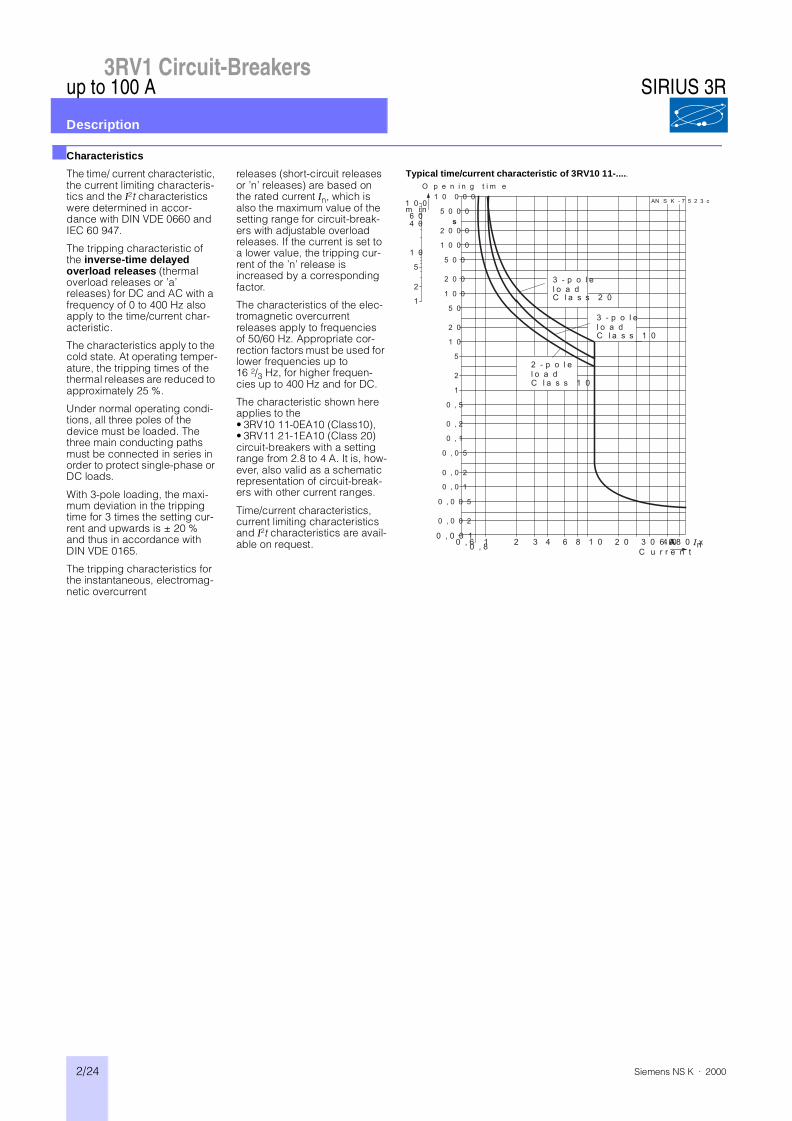
The characteristic shown here applies to the• 3RV10 11-0EA10 (Class10),• 3RV11 21-1EA10 (Class 20)circuit-breakers with a setting range from 2.8 to 4 A. It is, how-ever, also valid as a schematic representation of circuit-break-ers with other current ranges.
Time/current characteristics, current limiting characteristics and I²t characteristics are avail-able on request.
Typical time/current characteristic of 3RV10 11-.....
1 0
5
2
1
1 0 0 0 0
5 0 0 0
2 0 0 0
1 0 0 0
5 0 0
2 0 0
1 0 0
5 0
2 0
1 0
5
0 , 2
1
0 , 5
0 , 0 2
0 , 1
0 , 0 5
0 , 0 0 2
0 , 0 1
0 , 0 0 5
1 0 0
6 04 0
2
0 , 60 , 81 2 3 4 6 8 1 0
0 , 0 0 12 0 3 0 4 0 8 0 x n
N S K - 7 5 2 3 c
m i n
s
A6 0C u r r e n t
2 - p o l el o a d
O p e n i n g t i m e
A
3 - p o l el o a d
3 - p o l el o a d
C l a s s 1 0
C l a s s 1 0
C l a s s 2 0
SIRIUS 3R

3RV1 Circuit-Breakers
2/25Siemens NS K · 2000
up to 100 A
Description
■Mountable accessories
The 3RV1 circuit-breakers have three main contact elements. In order to achieve maximum
flexibility, auxiliary switches, signalling switches, auxiliary releases and isolator modules
can be supplied separately. These components can be fit-ted as required on the
circuit-breakers simply and without using tools.
Front Transverse auxiliary switch An auxiliary contact block can be inserted transversely on the front. The overall width of the circuit-breakers remains unchanged.
1 changeover contact or 1 NO + 1 NC
Left-hand side Lateral auxiliary switch1 NO + 1 NCor2 NOor2 NC
One of the three auxiliary switches can be mounted laterally for each circuit-breaker. The contacts of the auxiliary switch close and open together with the main contacts of the circuit-breaker.
The overall width of the lateral auxiliary switches is 9 mm.
Signalling switchfor sizes S0, S2 and S3
One signalling switch can be mounted on the side of each circuit-breaker with a rotary operating mechanism. The signalling switch has two contact systems. One contact system always signals tripping, irrespective of whether this was caused by a short circuit, an overload or an auxiliary release. The other con-tact system only switches in the event of a short circuit. There is no signalling as a result of switching off with the handle.
Trip 1NO+1NCShort circuit 1NO+1NC
Auxiliary switch and signalling In order to be able to reclose the circuit-breaker after a short circuit, the sig-nalling switch must be reset by hand after the cause of the fault has been removed.
switch can be mounted separately or together.
The overall width of the signalling switch is 18 mm.
Right-hand side Shunt release For remote-controlled tripping of the circuit-breaker. The voltage coil of the release should only be energized for short periods. 1)
Note:No accessories can be mounted oron the right-hand side of the 3RV1 circuit-breakers with an overload relay function.
Undervoltage release Trips the circuit-breaker when the voltage is interrupted and prevents the motor from being restarted accidentally when the voltage is restored. Used for remote-controlled tripping of the circuit-breaker. Particularly suitable for EMERGENCY STOP disconnection via the appropriate EMERGENCY STOP button in accordance with DIN VDE 0113.
or
Undervoltage releasewith leading auxiliary contacts(2 NO)
One auxiliary release can be mounted on the circuit-breakers in each case.
Operation and use as for the undervoltage release without leading auxiliary contacts, but with the following additional function: the auxiliary contacts iso-late the undervoltage release from the system on both sides when the circuit-breaker is open, thus preventing the formation of vagabond voltages in the control circuit in the OFF position. In the "tripped" position of the breaker, these auxiliary contacts are not guaranteed to open. The leading contacts permit the circuit-breaker to reclose. The overall width of the auxiliary releases is 18 mm.
Top Isolator module for circuit-breakers
Isolator modules can be mounted on top of S0 and S2 circuit-breakers.
Sizes S0 and S2The isolator module covers the ter-minal screws of the transverse aux-iliary switch. If the isolator module is used, we therefore recommend either that the lateral auxiliary switches be fitted or that the isola-tor module not be mounted until the auxiliary switch has been wired.
The supply cable is connected to the circuit-breaker via the isolator module. A removable plug, which can only be unplugged when the circuit-breaker is open, isolates all 3 poles of the circuit-breaker from the system. The shock-protected disconnection point is clearly visible and can be secured by means of a padlock to prevent reconnection of the plug.2)
1) See circuit diagram on page 2/28.2) See circuit diagrams on pages 2/28 and 2/29.
SIRIUS 3R