shodhganga.inflibnet.ac.inshodhganga.inflibnet.ac.in/bitstream/10603/57932/12/12_chapter 3.pdf · -...
TRANSCRIPT

CHAPTER 3
MASS BALANCE AND THEORETICAL CALCULATIONS
This chapter deals with the mass balance calculations for the melt and other theoretical
calculations related to the reduction of composite pellets in smelting reduction process.
An attempt is made to develop a mathematical model/formulation for mass balance in
smelting reduction process and empirical relations for calculation of degree of reduction
for composite pellets.
The basis for mass balance calculation can either be weight (1 kg or 1 tonne) or mole (1
mole). From industrial application point of view, weight-basis is more useful and has far
greater relevance than molar-basis. In fact, it is more convenient to make efficient use of
materials by weighing than that by counting moles. Therefore, weight is taken as the basis
for development of mathematical model/formulation for mass balance calculations.
3.1 Importance of Mass Balance
The product output of any process depends on the amount of raw materials consumed and
the chemical reactions taking place. Aim of mass balance calculations is to estimate the
in-flow and out-flow of materials. These are essential part of plant records and routine
calculations for plant operation. Such exercise is widely employed to obtain the accurate
composition of a product with available raw materials and also for design of furnaces. A
relatively complete accounting can be made from the knowledge of what species goes
into the system and what species comes out from the system, with little or no need to
consider the complexities and mechanisms of the processes within the system [156].
Before attempting to calculate the raw material requirements of a process, it is desirable
to first obtain a clear picture of the process. The best way to do this is to draw a block
diagram. These are very important for saving time and eliminating mistakes.

89
3.2 Material Balance Procedure
Material balance is essentially an application of the law of conservation of mass, i.e., the
mass of an isolated system remains constant irrespective of the changes occurring within
the system. It forms a sound basis for material balance calculations. The following
equation describes in words the principle of general material balance applicable to
processes both with and without chemical reactions.
' Accululationof mass') ( Inputthrough
K within the system ) {system boundariesr Output through '
v system boundaries.(3.1)
The above equation can be written simply as:
(Accululation) = (Input) - (Output) ..........(3.2)
The equation reduces further when there is no accumulation within the system, i.e.,
steady state. In that case one can write:
(input) =.(Output) ....... ..(3.3)
This is applicable to a batch process which involves treatment of a given mass of
materials in a process after which the products are taken out. If a process is operated such
that, over long periods, continuous streams of materials enter into the processing unit and
continuous streams leave the same then it is called a continuous process. In such a
process, one is concerned with the rate of input and rate of output of materials. If the
continuous process runs at steady state, then the chemical compositions of the input
materials and output materials remain unchanged and there can be no accumulation
within the system either. In such a situation, the material balance equation is written as:
(Rate of input of materials into the system)
~ (Rate of output of materials from the system) ..........(3.4)
In other words, for both batch process and continuous process, whatever goes in that must
come out. It should be noted that material balance holds on the total mass of materials but
not on moles. For material balance, a convenient basis of calculation is to be chosen. In
continuous processes, it is either unit time (per hour or per day) or unit mass of product

90
(e.g. one tonne of hot metal production for the blast furnace). For batch process, it is
either the entire batch or unit mass of product [156].
3.3 Development of Mathematical Model for Mass Balance
Cast iron scrap -
, Composite pellets -
Oxygen -
Fig. 3.1: Block diagram for melting in an induction furnace.
The process of smelting of composite pellets in an induction furnace is represented by the
block diagram as shown in Figure 3.1. The input and output of the process are shown
there itself. Table 3.1 also shows the input and output of the smelting of composite pellets
in an induction furnace.
Table 3.1: Input and output (mass balance) of smelting process
Input (kg) Output (kg)
Cast iron scrap (Wj) Hot metal (W3)
Composite pellets (W2) Gases and volatiles (W12, Wi3> W2o,
W21)
Oxygen required from atmosphere (Os) Slag (W22)
Total input = (Wj + W2 + Og)Total output = (W3 + Wi2 + Wj3 + Wi9 +
W20 + W2, + W22)
Assumptions:
i) Basis of mass balance calculation is one tonne of hot metal produced,
ii) Loss of iron (Fe) to slag occurs in the form of FeO,
iii) Removal of sulphur occurs in the form of CaS only,
iii) No other elements (including iron) are oxidized during melting of cast iron scrap,
iv) 90 pet of carbon forms CO gas and remaining 10 pet forms CO2 gas, and
vi) Fe203 present in composite pellets is reduced by the carbon present in composites.
Gases

91
Iron (Fe) balance
Fe input = Fe output
=> (Fe coming from cast iron scrap + Fe coming from composite pellets)
= (Fe present in hot metal produced + Fe loss to slag) .......... (3.5)
( W{x /, + W2xFixF2xFi^f100 100x100x100
F ^| _ x 4
100W3xl2
100
1 x W,xL +-±W,xF,xF,xFA
i "*1100
(W2xFlxF2xF3)104
104m~F4\_^w3xi2
100 (W3xl2) (100-K)
100
■(^xJJ
100
Therefore, weight of composite pellets require(W2),
W,104
^ x F2 X F3100 (w3xl2)
(100- F4)(W.xf) .(3.6)
Iron (Fe) loss to slag with respect to total Fe input, (W4)
= (Total Fe input) x (Pet of Fe loss to slag)
= (Fe coming from cast iron scrap + Fe coming from composite pellets) x
(Percent of Fe loss to slag)
W.W, xI. W,xF,xFtxF
100 1
’-+ 2100x100x100
A100
Fe + ~~0= FeO
(56) (16) (72)
Since, weight of FeO form, Ws 7256
xWA
Now, by substituting the Eq (3.7) in Eq (3.8), we get
We 72 F4 56 X 104 (T.xl,) +
fW2xFlxF2xF3 104
(3-7)
••(3a)
(3.8)
........(3.9)
Weight of oxygen require for oxidation of Fe loss to slag (Oi);
16Since, O,56
■xWa
16 FdO, = —x56 104
(W} x /. ) + W2 x Ft x F2 x F3 104
\6_72
x W5 ..... (3.10)

92
SiC>2 balance
SiC>2 input = Si02 output
=> (Si02 in terms of Si present in cast iron scrap + SiC>2 present in iron ore of composite
pellets + SiC>2 present in lime of composite pellets + SiC>2 present in coal ash of
composite pellets) = (Si02 in terms of Si in hot metal produced + SiC>2 goes to slag)
........ (3.11)
Wtxl3 (60 ).W,xF,xF WaxZ,xL,.W,xQxAlxA,100
~j_-
100x100v28,[Si + 02 = SiO?]
(28) (32) (60)
Since, 28 kg of Si forms 60 kg of SiC>2
'2 + ”2
100x100 100x100x100 100^60^
V28y+ W<
.(3b)
100Kg of Si forms 60 (ff,x/3)
28X 100 ~~ Kg of Si02
Therefore, weight of Si02 goes to slag(W6):
WA=- 60 W,(WlxI3-W3xI4) + -f- (F1xF5) + (L1xL2) +28x 102 1 3 3 4 104
Now, weight of Si02form due to oxidation of Si (fj): 60
(Cj x Ax x Af)loo .(3,12)
7 =■ -(WixI3-W3xI4)28xl02
Weight of oxygen require for oxidation of silicon (O2):
32
.(3.13)
a =28x 102
(W}xI3~W3xI4) .(3.14)
MnO balance
MnO input = MnO output
=> (MnO in terms of Mn present in cast iron scrap + MnO present in iron ore of
composite pellets + MnO present in coal-ash of composite pellets) = (MnO in terms
of Mn present in hot metalproduced + MnO goes to slag) ............... (3.15)
W.xL(n') W7xF,xF.I *5 I 2 16 ,
100 v55J 100x100
Mn +—07 = MnO
W2xClxAlxA3 _W3xI6 100x100x100 ~ 100
71155. + W,
.(3c)
(55) (16) (71)

93
Therefore, weight of MnO goes to slag(W7):
71 W.Wn =
71 W ( „ „ C, x A. xl''fxxf6 + 1 1 3
VWeight of MnO form due to oxidation of Mn (Y2):
71
100 7
T, =55x10"
-(^x/5-r3x/6>
.(3.16)
.(3.17)
Weight of oxygen require for oxidation of manganese (O3):
160,=
55xl02 (^x/5-fF3x/a) .(3.18)
P2OS balanceP2O5 input = P2O5 output
=> (P2O5 in terms of phosphorous present in cast iron scrap + P2O5 present in iron ore of
composite pellets + P2O5 present in coal-ash of composite pellets) = (P2O5 in terms
of phosphorous present in hot metal produced + P2O5 goes to slag) ........(3.19)
Wsxl7 f 142
62100| W2xFlxF7 W2 x C, x A, xA4 W, x L ^142^
100x100 100x100x100 100 62;
ip+-o2=p2o5
(62) (80) (142)
Therefore, weight of P2Os goes to slag (W$):142 W f „ _ CtxA,x A4Fx x p7 4- !—1 4
v 100
.(3d)
................(3.20)
Weight of P2O5 form due to oxidation of phosphorous (Y3):
142 (W^f-W^xf)62xl02
Weight of oxygen require for oxidation of phosphorous (O4):
oA80
62x10"■(wixI7~W3xIs)
.(3.21)
.(3.22)
CaO balanceCaO input = CaO output

94
=> (CaO present in lime of composite pellets + CaO present in coal-ash of composite
pellets) = (CaO goes to slag + Loss of CaO in the form of CaS to slag) ....... (3.23)
W2xLlxLi W2 x C, x At x (E + wu)100x100 100x100x100
Therefore, weight of CaO goes to slag (W9):
Wa E10'
Lj x Lj +Cj x A, x Ai
100(3.24)
AI2O3 balance
AI2O3 input = AI2O3 output
=> (AI2O3 present in iron ore of composite pellets + AI2O3 present in coal-ash of
composite pellets + AI2O3 present in lime of composite pellets) = (AI2O3 goes to slag)
............ (3.25)
W2xFjXFs W2xC1xA1xA6 + W2xfxL4 ..100x100 100x100x100 100x100
Therefore, weight of A1203 goes to slag to (Wl0):
W,10 E10' V
C, x A. x A,Fx x Fx +—1------------ + fxL41 8 J00 14 (3.26)
MgO balance
MgO input = MgO output
=> (MgO present in coal-ash of composite pellets + MgO present in lime of composite
pellets) = (MgO goes to slag) ............. (3.27)
_ W2xClxAlxA7 | W1xLixL5 ff 100x100x100 100x100 11
Therefore, weight of MgO goes to slag(Wn ):
W„10
( Ctx As x A7 100
+ fx L5 (3.28)
Carbon balance
Carbon input = Carbon output
=> (Carbon coming from coal in composite pellets + Carbon coming from cast iron scrap)
= (Carbon present in hot metal produced + Carbon converted into CO and C02 gases)
............... (3.29)
95
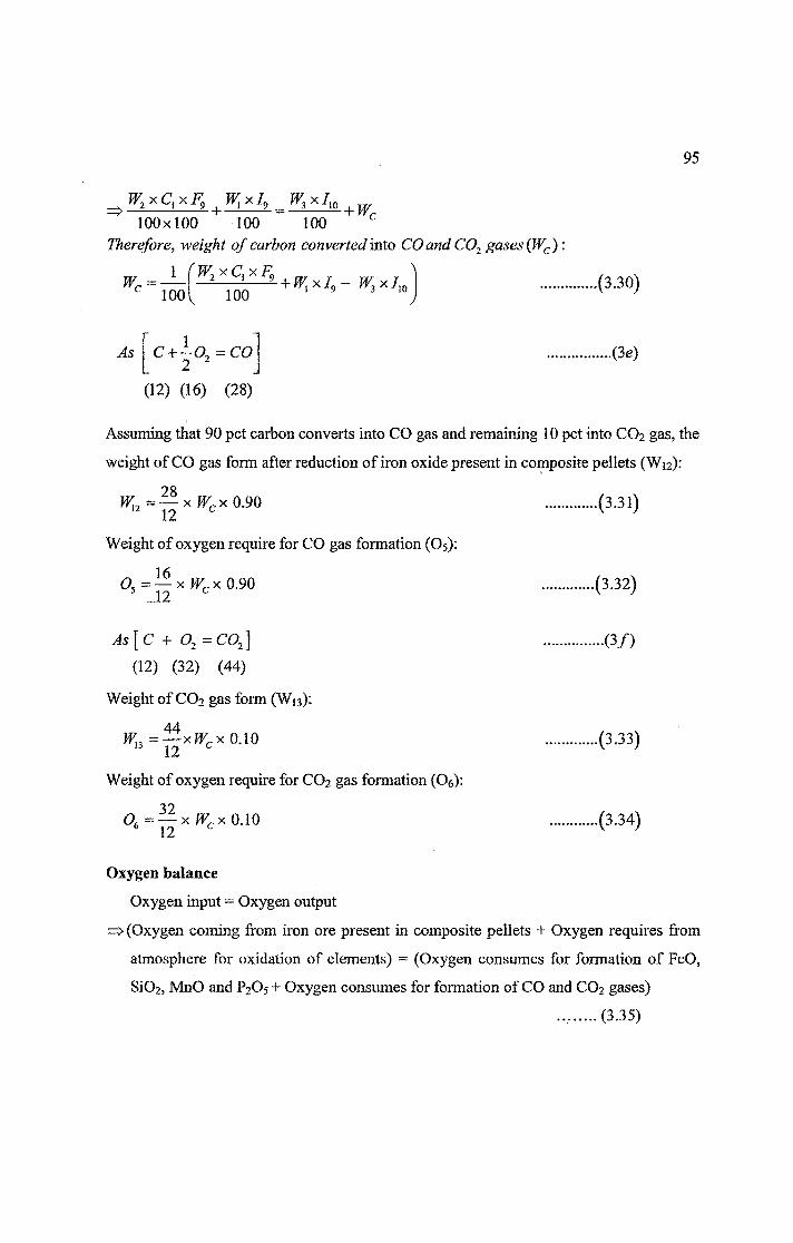
y3x/10100x100 100 100 c
Therefore, weight of carbon converted into CO and C02 gases (Wc):1 (W2xClxF9 r ^
---------2-----!---- - + W,xL1001 100 1 9IF, .(3.30)
As C + -02 =CO 2
(12) (16) (28)
•(3c)
Assuming that 90 pet carbon converts into CO gas and remaining 10 pet into CO2 gas, the
weight of CO gas form after reduction of iron oxide present in composite pellets (W12):
28W„ = — x Wcx 0.9012 12 c
Weight of oxygen require for CO gas formation (Os):
0 = —x fFcx 0.90 5 A2 c
.(3.31)
.(3.32)
As ( C + 02 — C02 J
(12) (32) (44)
Weight of CO2 gas form (Wo):
44W.,=—xWcx0.10 13 12 c
Weight of oxygen require for CO2 gas formation (06):
32O, = — xWcx 0.10 6 12 c
•(3/)
.(3.33)
.(3.34)
Oxygen balance
Oxygen input = Oxygen output
=> (Oxygen coming from iron ore present in composite pellets + Oxygen requires from
atmosphere for oxidation of elements) = (Oxygen consumes for formation of FeO,
Si02, MnO and P2O5 + Oxygen consumes for formation of CO and CO2 gases)
..... (3.35)

96
As Fe203->2Fe + ~02
(160) (112) (48)
(3 s)
Oxygen coming from iron ore present in composite pellets (O7):
O -(WixFixF2):: 48 7 100x100 } 160
Now, Oxygen require from atmosphere for oxidation of elements (Og):
=> Og = (Oxygen consumes for formation of FeO, Si02, MnO and P2O5 + Oxygen
consumes for formation of CO and CO2 gases) - (Oxygen coming from iron ore
present in composite pellets)
=> 08 = [(Oi + 02 + O3 + O4 + Os + 06 ) - 07] .......... (3.37)
Sulphur balanceSulphur input = Sulphur output
=> (Sulphur coming from cast iron scrap + Sulphur coming from coal-ash present in the
form of SO3 in composite pellets) = (Sulphur present in hot metal produced + Sulphur
goes to slag) .......... (3.38)
s + y2o2=so3 ............ (3 h)(32) (48) (80)
^x/,,^ (32
100+
80W2xCjxAlxAs100x100x100
\ (w xl }yvl A J\2)
00 + W,A
Therefore, weight of sulphur goes to slag(Wl4 ):1 W f 32',
W™ =—(IF, xlu - W3xln)+ —^-x — x(C, xAt x 4)l02v • *« ■> 106 (80,
As [CaO + S CaS + ]/2 02]
(56) (32) (72)
Amount of CaS form due to reaction of sulphur with CaO (W15):
(3.39)
,..(3i)
7232
*W,14 (3.40)
Amount of CaO that converts into CaS (Wi6):
Wu = ^-xWls 16 72 15 (3.41)

97
Other balances
Amount of other oxides except Si02, MnO, FeO, AI2O3 and P2O5 coming from iron
ore present in composite pellets (Wn):
m.17 (3.42)100x100
Amount of FeO (W18) that goes to slag due to presence of Fe203 in coal-ash:
As [Fe + Fe^ -*WeO} ........... (3j)
(56) (160) (216)
WiQ216 fW2xClxAlxAg'^
100x100x100160 vAmount of dextrose present in composite pellets (W19):
W,B(W2xFu'
100 }
Amount of volatile matters present in coal of composite pellets (W2o):
W,20
>'W2xClxFn
v 100x100 j
Amount of moisture present in coal of composite pellets (W21):
W,21
rW2xC{xFlA '
K 100x100 j
Weight of slag produced (W22):
W22 = (W5 + Wg + W7 + Wg+ W9+ W10+Wn +Wjs + W17+ Wig)
.(3-43)
.(3.44)
.(3.45)
.(3.46)
(3.47)

98
3.4 Stoichiometric Coal Requirement for Reduction of Iron Oxides
Fe203 + 3 C = 2 Fe + 3 CO ........... (3.48)
(160) (36) (112) (84)
Since, reduction of 160 kg of Fe203 requires 36 kg of carbon
T 36 ").'. Reduction of W kg of Fe203 requires ---- xW kg of carbon ............ (3.49)
160
Since, W = WBx^~ 0 100
and, F2160112
xFI,
10
.(3.50)
.(3.51)
From Eq (3.49) to (3.51), we get:
IF36160
160 KxWn x---- x 10
36112 100
-xW0xFm112x100
Since, Fg kg of carbon is present in 100 kg of coal
f 36 ^
.(3.52)
112x100xW0xF10 kg of carbon will be present in
^100x36 xW0xFw^
K F9 x 112x100kg of coal
rQ32l4xW0xW10^
F0kg of coal. .(3.53)
Alternatively, it means that
kg of coal is required for the reduction of W0 kg of iron orer032UxW0xFlo^
v
Here.
Fe
Fe.,0.3214
If
V tot ^stoichiometric ratio
tot _ „
'fix
The amount of coal required for reduction of W0 kg of iron ore in composite pellet (Wcoai):
Wn x F,nW,coal
r0 ^ J 10
rxFa(3.54)

99
3.5 Measurement of Degree of Reduction
The degree of reduction can be obtained through single measurement of weight loss when
a gaseous reductant is used. For reduction of iron oxides by carbon, the degree of
reduction can not be found out directly from the weight loss of the sample, since this is
made up of both oxygen and carbon losses. It is not possible to delineate the two unless
the released gases are analyzed and their volumes are measured. Accordingly, such
reactions have been studied with the help of gas chromatograph attach with the reduction
chamber. Even this method runs into trouble when coal is used in place of carbon.
Alternatively, the reaction product can be chemically analyzed after each test run, but this
procedure is time consuming, more expensive and would give only intermittent
information.
For ore-coal composite pellets, the weight loss of the sample arises not only from oxygen
and carbon loss, but also the loss of volatile matters and residual moisture present in
pellets [8]. Since only weight loss of the sample is not sufficient, some additional
measurements are required for estimating the degree of reduction (a), which is defined
as follows.
weight of oxygen removed from iron oxide xlOOtotal weight of remvable oxygen present in iron oxides AW
= —r~xl00 ........... (3.55)W‘
3.5.1 Review of methods for measurement of degree of reduction in composite
pellets
For determining the degree of reduction for carbothermic reduction, research workers
have employed various techniques. Most of the investigations have employed carbon,
such as graphite, coconut char and coal char as reductant. In these cases, the product gas
consists of CO and CO2 only and its analysis is straight forward. However, that would not
be the case if coal is used, because the other gases such as H2, CH4 etc would also be
present.

100
Reeve et al [157] determined the rates of reduction of the composite pellet with iron
oxide and char or coke. The progress of reaction was monitored by the increase in
pressure within the constant volume system as measured by 0 to 760 mm absolute
pressure transducer connected to a side arm in the cold part of the system. No information
is available about the method of calculation of degree of reduction.
Srinivasan and Lahiri [158] mixed powders of natural hematite and graphite and prepared
pellets by hand for reduction studies. They measured the progress of reduction with time
by noting the weight changes in the pellet and product gas analysis. The amount of CO2
absorbed in a given time interval was determined from the increase in weights of the
absorption tubes. The amount of CO present in the out coming gas stream was
determined from the weight change and CO2 absorption data. At any instant, the degree
of reduction was evaluated from the above data.
Shrivastava and Sharma [159] prepared a core pellet from the mixture of iron ore and
coal and further coated it with the iron ore only. They determined the degree of reduction
by using Eq. (3.55). Loss in weight due to carbon loss was calculated by estimating
remaining carbon content in reduced pellet after each reduction. It was not clear how it
was done. Oxygen loss was calculated by subtraction of other losses.
Dey et al [160] studied the reduction characteristics of hematite-noncoking coal
composite pellets (size of fines from 40 to 80 pm, 10 mm pellets), and they found that
reduction follows mixed kinetic laws which are dependent on temperature as well as on
the degree of reduction. The data for 1173 K and 1223 K are fitted well by Jander’s
model. At 1273 K and above, and for a values less than 0.5, the data are fitted by a parabolic model (a~ t2), and for a values greater than 0.5, the data are fitted by Jander’s
model.
Prakash [150] carried out non-isothermal kinetic studies on reduction of iron ore-coal mixture under increasing temperature conditions up to 1273 K at 15 K min'1. No external
gas was used and the samples were allowed to establish their own atmosphere.
Simultaneous thermal analysis plots showed step wise reduction of iron ore (coupled with
oxidation of coal) and a change of reaction mechanism at about 973 K. In the case of

101
thennal analysis data the degree of reduction (a) was expressed in terajW.of a pseudo-
kinetic parameter, the fraction of reaction (fg), defined as: \
Jr = (weight loss at time t) / (maximum possible weight loss) .........(3.56)
Dutta and Ghosh [27] employed non-isothermal method to determine the degree of
reduction for iron ore-coal composite pellet. They passed argon at known flow rate
through the reaction chamber containing composite pellet and then to analyze the
composition of exit gas by gas chromatograph at several interval of time. In another
method, further reduction of the partially reduced composite pellet was earned out by
hydrogen in a thermogravimetric set-up. This allowed measurement of residual oxygen of
iron oxide present in the partially reduced composite pellet and thus determination of
degree of reduction.
The degree of reduction, a=^AW0 !W'0 ) x 1 (JO ...........(3.57)
Where, A W0= weight of oxygen removed from iron oxide
W'Q = total initial weight of oxygen present in iron oxide
i) Rate of oxygen loss (W* in g.s'1) associated with evolution of CO and CO2 was given
as
W, 16 Q x(xco+2Xco:) .(3.58)22400,
Where, Q = total gas flow rate at the exit, cm3.s_l
X; = volume fraction of species i (CO, C02, CH4 and 1C).
By graphical integration of as function of time, total oxygen loss from iron oxide
(A WQ in g) due to evolution of CO and C02 can be estimated as:
AW,, [W0d, Where, t is the time in second.
ii) From Eq. (3.57); the degree of reduction can also be calculated after hydrogen
treatment,
a-AWn ]—4*. x 100
\K J w;.xlOO (3.59)

102
Where, tsWf = total oxygen loss during hydrogen reduction.
Hence, from oxygen loss data of hydrogen reduction of reduced pellets and total initial
oxygen of composite pellet before non-isothermal / isothermal reduction, the degree of
reduction can be calculated using Eq. (3.59).
Agrawal et al [161] prepared composite pellets of iron ore and coal using dextrine as
binder. They used fraction of reaction (fg) to study the extent of reaction of ore-coal
composites. Isothermal reduction tests were performed at 1223 to 1373 K for 5 to 60
minutes. Reduced pellets were analyzed for fraction of reduction ‘F’ values, whereas ‘fg
values were obtained from weight loss measurements. Fraction of reaction (fg) is defined
as the ratio of weight loss of reacting mixture to the maximum possible weight loss
(MPWL). This MPWL could be either the theoretically determined weight loss or an
experimentally determined value. Based on the definitions of ‘F’ and ‘ff, a theoretical
relationship between these two parameters was established [162]. The relationship can be
expressed as:
^ ^ Weight loss from coal''
KA.......... (3.60)
Where, F = fraction of reduction,^ = fraction of reaction, Ki = Pet oxygen in ore, K2:
Pet (moisture + volatile matter + fixed carbon) in coal, Fj = Pet ore in the pellet, and Cj =
Pet coal in the pellet.
El-Geassy et al [46] prepared iron ore-fuel oil composite pellets containing 5 to 15 pet
fuel oil as a binder and reducing material. These composite pellets were isothermally and
non-isothermally reduced at 1023 tol273 K in a flow of H2 and N2 gases. The total
weight loss resulting from oxygen removal from the reduction of Fe203 and from the
thermal decomposition of fuel oil was continuously recorded as a function of time at
different reduction conditions. The actual reduction extent at a given time was calculated
from the chemical analysis of partially reduced samples at a given time and temperature.
Santos and Mourao [48] studied the reaction between iron oxides and carbon at
temperature higher than 1473 K employing solid carbon or carbon dissolved in liquid
iron as reductant. Iron oxides-carbon composite pellets were submitted for

103
thermogravimetric analysis under inert gas in the range of 1473 to 1623 K. The fraction
of reaction (fR) was calculated by employing the expression,
fn = W,-W.A W_,
(3.61)
Where, W; - initial weight of pellet
Wt= weight of pellet at time t
AWmax = maximum weight loss attained by the pellet
Mourao et al [163] studied the kinetics of the carbothermic reduction of iron oxides using
different materials (iron ore-charcoal composite pellets and iron ore-coke composite
pellets) in the temperature range 1173 to 1373 K under argon and C/Fe203 ratio of 3. The
main experimental technique employed was thermogravimetry in which the weight of the
sample was registered as a function of time. Both isothermal as well as non-isothermal
reduction studies were carried out and the parameter employed in the kinetic analysis was
the reacted fraction (F), defined as:
A Wt _ W0-Wt W0~Wf
(3.62)
Where, W0 = initial weight of the sample
W, = weight of sample at time t
Wf = final weight of the sample attained in the experiment
Yang et al [164] prepared hematite-graphite composite pellets using a cold isostatic press
and studied the carbothermic reduction of hematite in hematite-graphite composite pellets
in an induction heating furnace at temperatures of 1373 to 1673 K. By use of the
isothermal reduction method, effects of temperature, carrier gas flow rate and graphite
particle size on the carbothermic reduction rate of hematite were investigated
experimentally. A high frequency induction furnace (15 kW, 100 kHz) was used to heat a
graphite crucible in which a high temperature isothermal zone was maintained. The
reduction was greatly promoted because the contact area between the graphite and the
iron oxide particles was remarkably increased and the heat conduction was greatly
enhanced. Since increasing temperature can greatly activate the indirect reduction and the

104
carbon solution loss reaction, the carbothermic reduction of hematite was greatly
promoted.
With the assumption that the total amount of reduction of iron oxides by CO is equal to
the amount of the carbon solution loss reaction, the overall reduction can be expressed as:
Fe203 + 3C = Fe + 3 CO ............. (3.63)
Since the molar ratio of Fe203 to C in the hematite-graphite composite pellets is 1: 3, the
reduction degree (a ) can be defined as the ratio of the pellet mass loss to the theoretical
pellet mass loss on the assumption that the reaction (3.63) is completed. Thus the
reduction degree (a) can be given as follows:
(W0-Wf)xlOO a - ——------- --------
W0x
Where, Wo = weight of pellet before reduction (g)
W/= weight of pellet after reduction (g)
M; = molecular weight of species i (g/mol)
3 MCO
+3MC i
•wv-f/
Chowdhury et al [165] developed a semi-empirical model to determine the course of
reduction of iron ore-graphite composite pellets over time in a laboratory scale side
heated packed bed reactor attached with a tailor made bottom hanging thermogravimetric
set-up. The particle size of less than 150 pm for both the ore and graphite powders were
selected for the preparation of the composite pellets. The degree of reduction was
estimated through weight loss and corresponding gas analysis. Assuming no CO in the
exit gas, and neglecting any volatile loss, the degree of reduction (a) may be calculated
by using the following relationship:32 HT
— xWra=M------xlOO ........... (3.65)
Where, Wr is the weight loss during reduction, Wh is the weight of hematite in the pellet
and f0 is the fraction of oxygen in hematite.
However, by knowing the exit gas composition, the degree of reduction may be
calculated more accurately. If the volumetric ratio of C0/C02 in the exit gas is Z, the

105
atomic ratio of oxygen/carbon (O/C) in the exit gas may be expressed in terms of Z as
follows:
O = Z + 2 C~ Z+l (3.66)
The weight ratio of oxygen/carbon ( Wq/Wc) can also be expressed in terms of outgoing
gas composition Z as follows:
WQ _ Z + 2 16 4Z + 8 Wc Z + lX12“3Z + 3 (3.67)
and
W0 4Z + 8 W0+Wc ~ 7Z + 11 (3.68)
Then the degree of reduction (a) can be represented more precisely as
Wn
aW0 + WCJ
xW„
f.**k-x 100
4Z + 8 7Z + 11
xW-xlOO (3.69)
Wang et al [43] calculated the degree of reduction (a ) for iron ore-coal pellet as follows:
Total oxygen loss from iron oxidescc — —---- ---------------------------------------------------— xlOOTotal removable oxygen present in iron oxides
A m„ __=---- -xlOO ..........(3.70)
m0
Total weight loss of a pellet (Amt, g), after reduction, is represented by
Am, = Am/+ Am0 + Amc ........... (3.71)
Where, Amf= weight loss of volatiles in composite pellets, g
Am0 = weight loss of oxygen in iron oxides, g
Amc - weight loss of carbon in composite pellets, g
Again, Amf =mxfv .......... (3.72)
Where,/, = factor of devolatilization for iron ore-coal pellet
m = initial weight of composite pellets, g
Suppose that the final reactive result of reduction of iron oxides by carbon can be treated
as a non-elementary homogeneous reaction:

106
FexOy + C = FexOy-i + CO .......... (3.73)
12 3Therefore, Am = — x Amn x Am„ .......... (3.74)16 4
Now, Eq. (3.72) and (3.74) are substituted in Eq. (3.71) giving
3Am, = (m x/v) + (Am0) + (—x Ama)
7= (mx/J + (~xAm )4
■'■Am0 = “(wx/v)] ......... (3.75)
Now, Eq. (3.75) is substituted in Eq. (3.70) giving
a = ——[Am, — (m x )] x 100 ........ (3.76)lm0
Eq. (3.76) is the original equation developed by Wang et al to calculate the degree of
reduction (a ) for iron ore-coal pellet.
Now, this equation is further modified by the author by incorporating the following.
Total removable oxygen present in iron oxide can be calculated as:mo =mXforeXPoreXfo .......... (3;77)
Where, fore = fraction of ore in composite pellets
fo - fraction of oxygen in iron oxides
pore “ purity of iron oxide
m = initial weight of the composite pellets, g
Now, f, can be calculated as:
.......... (3-78)
Where, fcoa[ = fraction of coal present in composite pellets
fvm = fraction of volatile matters in coal
The fractional weight loss (/„/) of a pellet is represented by
f — Total weight loss of composite pellets _ Am,Initial weight of composite pellets m
Where, fvt = fractional weight loss of pellet

107
Amt = total weight loss of composite pellets, g
m = initial weight of composite pellets, g
Now, Eq. (3.77), (3.78) and (3.79) are substituted in Eq. (3.76) giving
xlOO
........... (3.80)
4a — — x 7
fcoal{mx forex porex
400 fwl C/coal ^ -fvm )7 (f x p X f )\J ore r'ore Jo/
Eq. (3.76) takes into account of total release of volatiles in composite pellets while
calculating the degree of reduction. However, the release of volatiles from composite
pellet is gradual and occurs over a wide range of temperatures (523 to 1200 K).
Therefore, the values of the degree of reduction (a) calculated by Wang et aPs Eq.
(3.76) at temperatures below 1200 K turn out lower than the actual degree of reduction.
Further, non-isothermal reduction of composite pellets by thermal analyzer does not
provide continuous recording of separate release of volatiles. Considering the above, a
term fw is incorporated in Eq. (3.80) and hence, the modified equation of Wang et al is as
follows:
400a -------x7
f . —{f , x f x f )J wl \J coal J vm J vr J
(f X p X f ) w ore r'ore Jo/
(3.81)
Where, fvr represents fraction of volatiles released at time t or at a particular temperature
during reduction. In present investigation, Eq. (3.81) is used to calculate the degree of
reduction of composite pellets.