3informat~c · pdf filei f abstract refractive index data and some extinction coefficients are...
TRANSCRIPT

AIR FORCE IYSTSMS COMMANDI ~~~antWae F3361-S-C-1225
-A.. 47. adOS9 3 S
Rpoduce by th.C L EA 1ZI N G OU SE Q7Lq--AtT 1970-o ederat Sc t-, & -,C&ncC-3Informat~c" SD gjfeld %,, 221.51
EPIC I mF9Di 4DCi0JW~
MUfAA.CKAFT COMPANY R D
LCULVER C1CALIFORNIA Q
This dcumnent has been approved for public release and sale;its distribution is unlimited.

* R.E FR.A.CTIVEr3 I3!+T3DEX.
I1q T7111E INFqRn1 A2REDM3 R 1 EQIONt
.&A,. JT. ML(.-,,SE3S9
rp -E IC
HUGHES
I ""
HUGHES AIRCRAFT CONPAYNCULVER CITY CALIFORNIA
IITTEIN R R DIl•O•

I F
ABSTRACT
Refractive index data and some extinction coefficients are provided
I for the infrared region for the following materials: silicon, germanium,
zinc sulfide, cadmium telluride, zinc selenide, silica, calcium fluoride,
magnesimn fluoride, aluminum oxide, magnesium oxide, aluminum,
gold and silver. The dependence of these optical constants on wave-
length, temperature, crystal form, film preparation '.echnique, radia-
tion and other factors is included.
This report has been reviewed and is approved for publication.
!
r Dr. Sheldon J. Welles, HeadElectronic Properties Information Center
E. F. Smith[" Project Manager

TABLE OF CONTENTS
Page
FOREW ORD ....................................
INTRODUCTION ................................
ABSTRACT ...................................
1. TECHNICAL INTRODUCTION ..................... 1-1
General Information .......................... 1-1
Optical Spectrum . ............................ 1-1
- - Materials Properties .. ............. ............ 1-1
2. DEFINITIONS OF REFRACTIVE INDEX AND FACTORSAFFECTING THE REFRACTIVE INDEX ............. 2-1
Definitions ................................. 2-1
Dependence on Wavelength .... ...................... 2-2
Dependence on Temperature ..................... 2-2
Dependence on Pressure ........................ 2-4
Dependence on Nuclear Radiation ................. 2-5
Dependence on Materials Preparation Techniques ........ z-6
3. METHODS FOR DETERMINING THE REFRACTIVE
INDEX ........................................... 3-1
Deviation .................................. 3-1
Reflection ................................. 3-3
Interference ...................................... 3-3
Transm ission .............................. 3-5
4. PROBLEMS ASSOCIATED WITH FILMS ............. 4-1
5. REFRACTIVE INDEX DATA FOR SEMICONDUCTORS .... 5-1
"Silicon ............................... ..... 5-5
Introduction ................................... 5-5
Dependence on Wavelength ................... 5-8
Dependence on Temperature .................. 5-17
* .7.
"A
- -•

[1 4.
TABLE OF CONTENTS (Continued)
Page"
Dependence on Pressure ..................... 5-ZZ
Dependence on Surface Condition. ............... 5-23
Germ anium ................................. 5-25
Introduction ..... ............................. 5-25
Dependence on Wavelength .................... 5-31
Dependence on Temperature ........................ 5-44
Dependence on Pressure ........................... 5-50
Dependence on Film Thickness ...................... 5-52
Dependence on Film Composition ............... 5-53
Dependence on Film Deposition Rate ............ 5-54
Dependence on Film Deposition Atmosphere ........ ... 5-55
Dependence on Film Deposition SubstrateTemperature ..................................... 5-59
Dependence on Electric Field .................. 5-61
Zinc Sulfide ................................ 5-63
Introduction ............................. 5-63
Dependence on Wavelength .................... 5-65
Cadmium Telluride ..... ........................... 5-75
Introduction ............................. 5-75
Dependence on Wavelength .................... 5-78
Dependence on Temperature .................. 5-90
Zinc Selenide ............................... 5-97
Introduction ............................. 5-97
Dependence on Wavelength ................... 5-99
Dependence on Temperature .................. 5-106
4,

TABLE OF CONTENTS (Continued)
Page
"6. REFRACTIVE INDEX DATA FOR SILICA-QUARTZ-
SILICOi DIOXIDE ........................... 6-1
General ... ................................ 6-1
Silica, Crystalline ........................... 6-3
Introduction ............................. 6-3
"Dependence on Wavelength ................... 6-5
Silica, Fused . .............................. 6-15
Introduction ............................. 6-15
Dependence on Wavelength ................... 6-17
Dependence on Temperature .................. 6-28
"Dependence on Radiation ...... ..................... 6-30
7. REFRACTIVE INDEX DATA FOR FLUORIDES ANDSELECTED CERAMICS ........ ........................ 7-1
"Calcium Fluoride ......... ............................ 7-3
Introduction ........ ............................. 7-3
Dependence on Wavelength ................... 7-5
Dependence on Temperature ................... 7-13
Magnesium Fluoride .......................... 7-15
Introduction ............................. 7-15
"- Dependence on Wavelength ..... .................. 7-16
Aluminum Oxide -Cornndum--Sapphire -Riby .............. 7-19
_ Introduction . ............................ 7-i9
Dependence on Wavelength ................... 7-23
SDependence in Temperature .................. 7-31
i-i

TABLE OF CONTENTS (Continued)
Page e -
Magnesium Oxide ............................. 733
Introduction ............................. 7-33
Dependence on Wavelength ........................ 7-36
Dependence on Temperature .................. 7-43
8. REFRACTIVE INDEX DATA FOR METALS .............. 8-1
Introduction ................................ 8-1
Data Summary .............................. 8-2
Aluminum . ................................. 8-5
Dependence on Wavelength .................... 8-5
Dependence on Temperature .................. 8-9
Gold ...................................... 8-11
Dependence on Wavelength ................... 8-11
Dependence on Temperature .................. 8-18
Dependence on Film Thickness ................ 8-19
Silver .................................... 8-21
Dependence on Wavelength ................... 8-21
Dependence on Film Thickness .............. 8-Z8
Dependence on Temperature .................. 8-29
9. BIBLIOGRAPHY ............................. 9-1
EPIC-Indexed References ....................... .9-1
Other References ............................ 9-13
ii
.P1
FOREWORD
This report was prepared by Hughes Aircraft Company, Culver
City, California, under Contract Number F33615-68-C-IZZ5. The work
was administered under the direction of the Air Force Materials Labora-tory, Air Force Systems Command, Wright-Patterson Air Force Base,
"Ohio, with Mr. B. Emrich, Project Engineer.
The Electronic Properties Information Center (EPIC) is a desig-
nated Information Analysis Center of the Department of Defence autho-
rized to provide information to the entire DOD community. The purpose
of the Center is to provide a highly competent sou-rce of information and
data on the electronic, optical and magnetic properties of materials of
value to the Department of Defense. Its major function is to evaluate,
compile and publish the experimental data from the world's unclassified
literature concerned with the properties of materials. All materials
relevant to the field of electronics are within the scope of EPIC: insu-
lators, semiconductors, metals, super-conductors, ferrites, ferroelec-
trics, ferromagnetics, electrolurninescents, thermionic emitters and
optical materials. The Center's scope includes information on over 100
basic properties of materials; information generally regarded as being
in the area of devices and/or circuitry is excluded.
The Center provides a technical answering service in which the
technical staff responds to inquiries ranging in complexity from simple
requests for data point values to requests for comprehensive reviews
of the literature. This service is available to U. S. Government agencies,
"their contractors, subcontractors, suppliers, and those in a position to
support the defense effort. Inquiries may be directed to:
Electronic Properties Information CenterHughes Aircraft Company"Bldg. 6: E-175Centinela and Tezle StreetsS• Culver City, California 9n•?!OCtrTelephone: (Z13) 391-0711 Ext. 6596
The EPIC Bulletin, published quarterly, announces new publica-
tions and current activitics of the Center. Users may request receipt
of the Bulletin on a regular basis.I
ifjg1

:i i. INTRODUCTION
These data sheets have been prepared to meet a need for infrared
refractive index information on optical materials with emphasis on high
temperature utilization. Sources of information for these data sheets
- include periodicals, reports, proceedings of meetings and vendor
literature. In addition to the 40, 000 entries in the EPIC files, non-
indexed material was also drawn upon to provide the desired degree of
cornoleteness. Inadequate materials characterization and differences
in experimental techniques have made it unwise to judge the quality of
F Lthe data and have resulted in a presentation of most of the data from
the literature. In addition to the dependence of the refractive index
and extinction coefficient on wavelength, the dependence on crystal form.
film preparation techniques, temperature and radiation are considered.
The designer will also find optical transmission plots and physical
property information to be helpful.1 |• The data sheets are organized in eight chapters comprising a
i 2- technical introduction, definitions, experimental measurement tech-
niques, problems associated with films, refractive index data for semi-
i Lconductors, fluorides and ceramics, and metals. For convenience, a
conversion table from wave number to wavelength ..s provided in the
• V Appendix. The bibliography is divided into two parts where the first
part lists references in the EPIC system, e.g., McCarthy (26010),
I and the second part lists non-EPIC references, e.g., Kodak[1967]., Users of the data sheets are encouraged to bring to the author's
attention omissions of appropriate data so that supplements will be
reasonably complete.
i I1--
lii
I
V

CHAPTER 1
TECHNICAL INTRODUCTION
GENERAL INFORMATION
This report provides a concentration of data for optical constants
of thirteen materials with emphasis on the refractive index in the
infrared region of the optical spectrum. Considerable extinction coef-
ficient data are also included as an aide to the design engineer. The
refractive indices and extinction coefficients are presented as a function
of (1) wavelength, (Z) temperature, (3) pressure, (4) materials prepara-
tion technique and (5) radiation environment.
OPTICAL SPECTRUM
The optical spectrum is illustrated in Figure 1-1. This report
emphasizes the infrared region between 0.8 and 1000 microns, though
some data for the ultraviolet and visible regions are included.
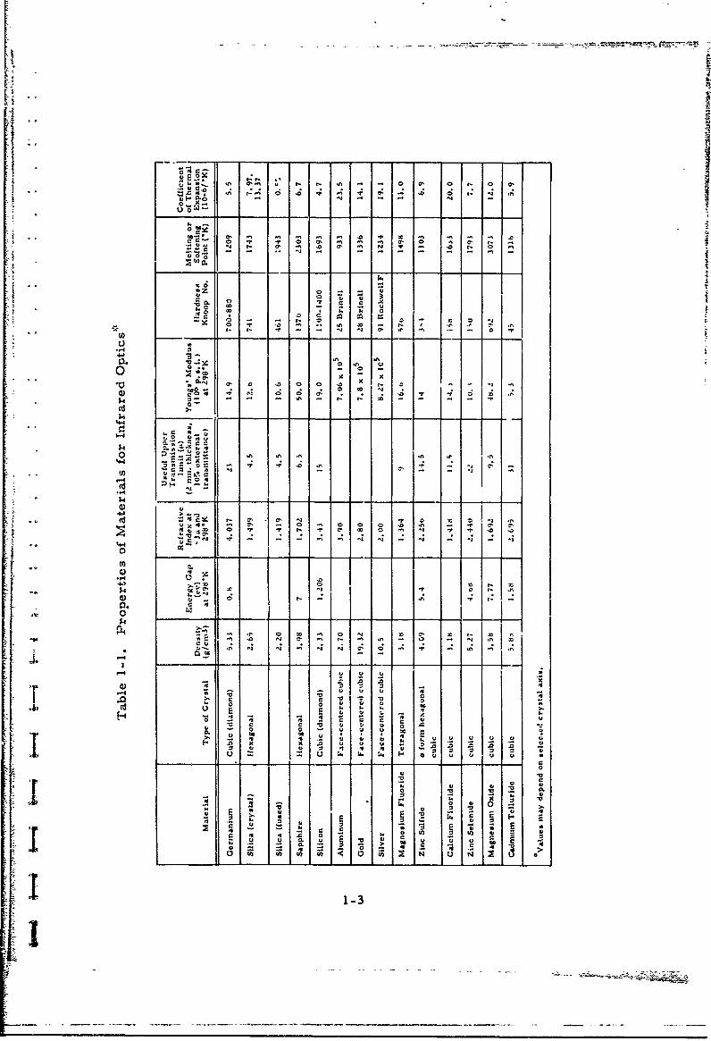
MATERIALS PROPERTIES
f, Properties of optical materials are summarized in Table 1-1.
"I [This table includes some physical and mechanical properties in addition
"to optical data and crystal structures because it is realized that the
selection of an optical material cannot be based on optical data alone.
Transmittance data for the infrared region are included as additional
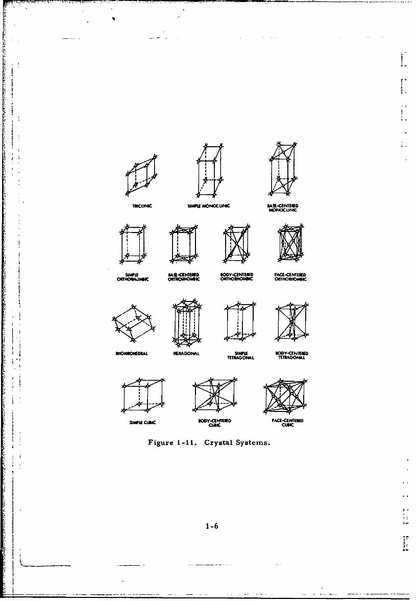
reference material (Figures 1-2 to 1-10). By their nature, cubic crys-
tals have isotropic properties and are therefore preferred for many
F -optical applications. Non-cubic crystals divide incident light into two
i •separate components which travel at different velocities and are con-
sequently refracted to different degrees. This phenomenon is called
"double refraction, " or, "birefringence. " However, crystals that are
F :tetragonal, hexagonal and rhombohedral have one axis along which
there is only single refraction. These systems have one optic axis and
are called "uniaxial, " whereas rhombic, monoclinic and triclinic crys-
tals are biaxial. Crystal classes for optical materials are included in
"Table 1-1 and are illustrated in Figure 1-11.
"" - 1-1

WAVELENGTH FREOUENCY BLACK-BODYIMICPGŽ14S) TEMP
CPS c MDEG ~
300 1012 10
100
-4x1O~
t o13o12
21
1-3
3':'
U 0
-0- V - 7 -a,
a-f 0 0
u a. 300 F . r. r 3 - - 0 0 - 0 0
go___k__M
C,1
40
0 0 z
Cl)l - -
444
4.'~~~ C~''3
- to I* toe' N .
x 0
$4L
~~00
A .A1-3

too.so
30 %T 2
25S 10 13 20 25 30 35 40'53 2 5 10 1520 2530 3540 45 50
WAVELENGTH, MIWCRONS WAVELENGTH, MICRONS
Figure 1-2. Silicon, 1 cm. Figure 1-3. Germanium, 1. 6 mm.
Ref. McCarthy (38757) Ref. McCarthy (38757)
/'F1.0 MM. EXTRAORDIARY DAY g
5020 5400 0 2 3 5 4 5 2
20 120
0 1-4u L
505 to S 0 4
WAVELFNG!AVEENGH. MICRONS WAENGH jos
Figure 1-6. Transmission in Far Figure 1-7. CacumeInfrared by Fuystlied Silica Fluoide, 5 mm.
Ref. Cartwright [19341 Ref. McCarthy (38757)
1-4
go %R

'10I . I 1 o
Ref. 1 Mc1arthy (2010)
350
4600
•" " "WAV•&ENGTH, MICRONS
Figre -. Tanmisio 1-or 2lmmTickPourmtlnOIrtra- Samplhies
*Z 30mm
•' RefReMc Kodak [1967]
-20-
W A TELENGTHMICRONS100
0 R• I l IRTR 3 I 2 I 4 , _
o i0
~~~ 20 0N 20 40Z0n 20 0
0 - _0 -- IT I0 MESI
1 29 30 10 1 120 1 140 15170 I 1 9 200 2 22 324 2 6202 93
WAVELENGTH, MICRONSFigur Figure 1 i0. Far Infrared Trans-t ' mission of high resistivity adTe
Sat 300 K and 8 KRef R Johnson, et al [40781]
"j . 1-5
IUCUNIC SwLlAP MONOCUI4IC Wg-a-C11EMONOCUNIC
SLW~LE aAI~~ OOY.CENW[ FACE-CENTEMOOBTHMOkq)&1 &U WI ORTIIOU4O)I ORTHORMAGIC
UIOAOOEORAL HEYAGOPAL Swil DODY-CENMl D
MERAGONAL TETRAGONAL
saawi cwlc seyuawn MaC-qmNmU
Figure I1-It. Crystal Systems.
1-6

L
[I
CHAPTER 2
DEFINITIONS OF REFRACTIVE INDEX AND FACTORS"AFFECTING THE REFRACTIVE INDEX
DEFINITIONS
The refractive index (n) of a material is defined as the ratio ofthe phase velocity (c) of electromagnetic radiation in vacuum to the
thephase velocity (v) of the same radiation in the material, or:
n = c/v
However, since the index of refraction of air is only about 1. 0003, it is
frequently measured with respect to air "nstead of vacuum and no cor-
"rection made for air.
-. In non-absorbing media, the refractive in,'tx is real, while in
absorbing media a complex index of refraction (N) . • sometimes used.
The complex index of refraction is frequently defined a.
N = n+ik
"where k = extinction coefficient or absorption index and i = fi-. Both
"- n and k are frequency-dependent.
The real and imaginary parts of the square of the complex refrac-
tive index satisfy the Kramers-Kronig relations, as follows:
22 2 2N = (n +ik) (n -k )+2nki
Sfco
n n 2 (w) k2 (w)) 2 f w'2n(w')k(w')dw' tantTr j w,2-_W2---0
oo
2n(w)k(w) = -2cw ( n 2 (w') - k 2w') dw'• • . 12 .0
=w2-1L _ _ _ _ _

This is, if the absorption index as a function of frequency is known,
both n(w) and k(w) can be evaluated separately.
Optically anisotropic materials divide incident light into two com-
ponents (double refraction) which are refracted along two mutually per-
pendicular planes. The ordinary wave travels at a velocity that is
independent of the direction of propagation. The extraordinary wave
travels at a velocity that is dependent on the relation between its direc-
tion and- the optic axis. Single refraction occurs for light that travels
parallel to the optic axis. The refractive index for the ordinary wave
bears the symbol no, while ne denotes the extraordinary wave. Both
n and ne are dependent on frequency. Most types of crystals are
anisotropic, giving rise to both no and ne. Cubic crystals have refrac-
tive indices that are identical in all directions (isotropic) for which
reason they are often used in optical instruments.
In this compilation, emphasis is placed on the refractive index
for-the ordinary wave and for simplicity the corresnonding refractive
index iz denoted by the symbol "n".
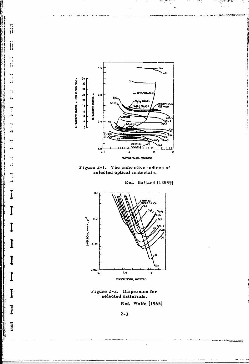
DEPENDENCE ON WAVELENGTH
The refractive index of optical materials is dependent on the wavc-
length of the incident light, as shown for the ordinary refractive index
of such materials in Figure 2-1. The refractive indices in Figure 2-1
range from about 1. 3 to greater than 33,with glasses in-the region
between 1. 3 and 2. 01 semiconductors between 3.4 and 4. 1, and metals
as high as 33.
The slope of curves from Figure 2-2, dn/dk, represents the
dispersion and the wavelength-dependence of dispersion is evident from
Figv.2e 2-2.
DEPENDENCE ON TEMPERATURE
The temperature coefficient of the refractive index is at least in
part affected by the thermal expansion of the optical material, as shown
by an approximate 10 percent contribution to the temperature coefficient
of the refractive index for germanium [Ref. Cardona (2569). ]
2-Z
lI, .. .
Ii ii _ _ _ _ _ _ _ _ _ _ _ _
4.0
-- In36
S326
0W 21 ---~02 Au (IVAPORAND)
SEEIUM
24 . - KI-
V 0 - w
" ----'--------"•• ý_" CslFUREDCd
" 1.o L01 QJARTz wi tTZ
0.1 1.0 10 60. t WAVEIENGTH, MICRONS
"Figure 2-1. The refractive indices ofselected optical materials.
Ref. Ballard (12539)
CaF2 As2S 3NOCI
0.01 A-CCI
KRS-5
i Kt Ci
0.001
0.0001 L I II I IS0.1 1.0 to
WAELENGTH,. M•CRO:
Figure 2-2. Dispersion forselected materials.
Ref. Wolfe [1965]
-i 2-3

F
Heating a material causes a change in its dimensions. This ""
change in dimensions is expressed by the linear coefficient of thermal
expansion. In most cases, this coeff'.-ient is positive, increasing with
rising temperature. The coefficient is usually small for optical
materials, as may be seen from Table 1-1 and is wavelength-dependent(Figure Z-3). The occurrence of phase changes in the material can cause
a major change in the coefficient of thermal expansion. For aniso-
tropic crystals, the thermal expansion is also influenced by the direc-
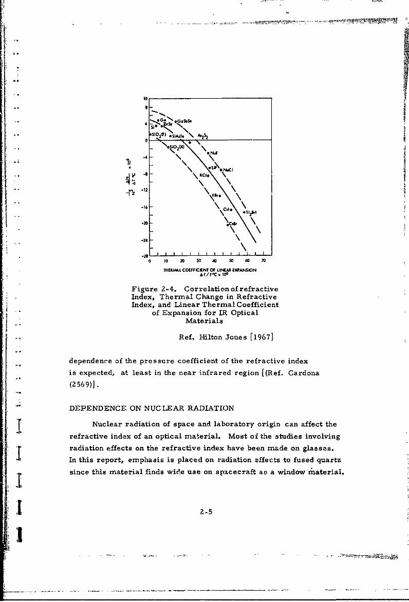
tion of the heat flow. The correlation bet% en refractive index, thermal
change in refractive index, and linear thermal coefficient of thermal
expansion for selected optical materials is demonstrated in Figure 2-4.
DEPENDENCE ON PRESSURE
Application of external pressure on a material affects the
Smaterial's refractive index in excess of changes attributable to com-
pressibility arxl i,; explkined by the existence of two effects due to
pressure; (1) change in electron density and (2) change in electronic
polarizability; the first effect produces an increase in refzactive index
with pressure, while the second effect reduces it. No wavelength-
4. 16'5
2 -Si 2 (AMORPHOUS)
0C-C0 3 N*CI~ Cal2 S0 2 (CRYSTALLNE)-- •-2%• • -. SiO2 (CRYSTALLINIE}) •
*2 . KCI
- 0.2 M--- O- S
0.1 0.2 0.4 0.60.41 2 4 6 8 10 20 40
WAVELEGT, MICRONS
Figure 2-3. Temperature Coefficient ofRefractive Index for Some
Optical Materials
"Ref. Smakula [1952]
2-4
*5
10
4 Z.S S
;S I(F)OiAsTe \ A'2%3
o_ (X.oc) ,,\ u
-4.
KC
~~-1o
%(. \-16*1 2 r
-20 .. d
-24
-28 - I I I I I - -I I j0 10 20 30 X0 50 60 70
THERMAL COEFFICIENT OF LINEAR EXPANSION&t/t.C . 106
Figure 2-4. Correlation of refractiveIndex, Thermal Change in RefractiveIndex, and Linear Thermal Coefficient
of Expansion for IR OpticalMaterials
Ref, Hilton Jones [19671
dependence of the pressure coefficient of the refractive index
is expected, at least in the near infrared region [(Ref. Cardona
(2569)].
DEPENDENCE ON NUCLEAR RADIATION
Nuclear radiation of space and laboratory origin can affect therefractive index of an optical material. Most of the studies involvingradiation effects on the refractive index have been made on glasses.
In this report, emphasis is placed on radiation effects to fused quartz
since this material finds wide use on spacecraft as a window riiaterial.
Z-

DEPENDENCE ON MATERIALS PREPARATION TECHNIQUE
The refractive index of a material is a function of the surface
condition and chemical composition. In the case of evaporated films,
the refractive index is also influenced by: evaporation atmosphere,
substrate temperature, substrate material and orientation, condensa-
tion rate, film thickness and source temperature.
2-6
i:V

CHAPTER 3METHODS FOR DETERMINING THE REFRACTIVE INDEX
Widely used methods for determining the refractive index of a
material are based on the following principles:
1. Deviation
2. Reflection
3. Interference
4. TransmisSionFundamentals of these methods will be discussed in this chapter. Data
tables in this report indicate which method was used to determine
refractive indices.
DEVIATION
Deviation methods, measuring the deviation of a beam of ligh,
from a known path, can be considered to be the classical approach.
Deviation methods use a prism and therefore cannot be used for
films. A typical deviation method is the prism deviation method, where
the light is refracted through the prism at a given deviation which need
not be the minimum deviation. Figure 3-1 illustrates the geometry ofthe prism, which permits calcuation of the refractive index as' shown
below. [Ref. Wolfe, et al (26316)J.
1 02
Snell's law provides the next pair of equations:
n 1 sin 01 = n 2 sin 0'1 "1
n sin 6 n sin '
33-1t

|2
2 N
Figure 3-1. Prism Geometryfor MWnimum and Normal
Deviation
Now a series of substitutions puts these equations in a furm thatsimplifies solution of n2/n1 :
n sin 61 = n2 sin (a-60z2)
n 12sin a cos 6'2 - cos o sin 0'2)
- n2 sin a (1 - sin2 O'2) 1/2 - cos a sin 012
nIsin 0') = - sin 02
sin () = sin a (n 2 /nl)2 - sin2 (2 1 1 2 - cos o sin 02
•,2 2
Ssin 20. +2sin 1 cosa sinO +cos asin0(n 2 /n 1 ) 2 = sin 2 0 + o 2 2
•• ~sin a •
2 sin 02 + sin2 O1 + sin 0 1 coso sin 0 2S(n 2 /n 1 )2 = -2
sino
n 1 2 2 1/2n = sin-- 0 +sin 2 + 2sin 1 sin02 cos&a)
3-2

[
REFLECTION
Reflection methods for determining optical constants are based
"on measurement of the reflection coefficient and the phase relationship
between the two components of the reflected radiation, where one com-
ponent is perpendicular to and the other component is parallel to the
- -. plane of incidence, as shown in Figure 3-2. In some reflection methbds,
both reflectivity and transmission must be measured but the data then
permit the calculation of refractive index and extinction coefficient
[Ref. Spitzer and Fan (791)].
A detailed description of a reflection method has been provided by
"Avery [Ref. Avery [1952J]. Avery's method briefly entails:
1. Determination of the ratio of the reflection coefficients (p )
for incident light polarized in and perpendicular to the plane
of incidence.
2. Let the complex refractive index be N = n(1 - ik), then at the
angle of incidence :
2 a2 + b2 - 2a sin etan0 + sin2Otan 2
a 2+ b2 + 2a sin 0 tan 6 + sin26tan 26
"where
N - sine2 = (a -ib) 2
23. From curves relating p to n and k for a number of angles of
incidence, and measurements at two or more angles of
{ incidence, n and k can be determined.
[ INTERFERENCE
In principle, interferometric methods are based on dividing the
j "light output of a source into two or more beams which are then super-
imposed. By illumination of parallel plates of a transparent material
with these superimposed'beams, reflection from the upper and lower
f3-3

E, E
Figure 3-2. Geometry for theReflection Method
Ref. Wolfe, et al, (26316)
surfaces will occur and an interference pattern will be created.
[Ref. Wolfe, at al (26316)].
The Variable Angle Monochromatic Fringe observation (VAMFO)
method represents an interferometric method for determining the thick-
ness and refractive index of transparent films on reflective substrates
using the apparatus depicted in Figure 3-3 [Ref. Pliskin & Fan (36787)].
The technique employs a rotating stage which is attached to an xy stage.
Maxima and minima (fringes) are observed as the stage and samples
are rotated, providinr- the number of fringes between angular limits.
A microscope provides magnification. The refractive index is given by
the equation.
AmXn-t (cosOe - cosO1 )
3-4

[I
4.7
FLUOIESCENT
/uGI4- MOWE
MONOCHROMATIC
IFIVER
I MIRROR
whe re
•; .. m ; number of fringes observed between refraction angles01 and 0 2
S• t = film thickness"�"F = waveingth of filtered light
S[ TR ANSMISSION
The transmission method for determining the refractive index of
Anfi ns is based on the following equations:
S"" 2nt = m \for maxzimum transmission
S-a and
2nt (m + kfor minimum transmission,
3-5

where
t = film thickness
= wavwlength of incident light
m = the order number
The order number can be determined by using the first equation in the
region of minimum dispersion, where the order number is low and the
product 2nt is essentially constant. The film thickness is measured by
other tests. [Ref. Wales, et al. , (31497)].
3-6

I- - 7-=" 7 7
I:- - - - - --S,: - - . . .• ÷ =••..= -•• -_•
CHAPTER 4
PROBLEMS ASSOCIATED WITH FILMS
The optical characteristics of films are sensitive to the film
microstructure, which in turn is affected by various deposition param-
eters. The formed film is subject to aging effects including oxidation,
recrystallization, hydrolysis, thermal decomposition, chemical reac-
tions with the environment, and other causes. As a result of these
factors, optical data for films often show a wide spread in values between
observers.
Optical films are most commonly deposited by thermal evaporation
in a vacuum onto a substrate that may be heated. Factors influencing
the optical characteristics of evaporated films include the following:
1. Condensation rate
2. Source temperature
3. Substrate material
4. Substrate temperature
5. Ambient pressure
6. Nature of ambient environment
7. Film thickness.
Specific results showing the effects of these factors on the refrac-
tive index are presented on appropriate materials data sheets in this
report. Some additional remarks relating to these faciors ser.e to
demonstrate the strong influence of some of the fa;,tors.
The presence of hydroxyl groups, ussuaiiy formed by the reaction
of water vapor with the material, causes an absorption band near Z. 7
micr%,ns and a low refractive index at that wavelength. Thia phenomenon
is most marked in sputtered, anodized, and electrodeposited films.
An example of aging is the growth of natural ox'fde, on alum-inum,
which h-s been reportedto reach a maxiijaum thicknes." of 45 Angstroms
in one month. Oxides usually have a different refractive index from
that of the matrix, as is illustrated in Table 4-1, where germanium,
silicon, aluminum and their oxides are compared.
4-1
1I"

Table 4-1. Comparison of Refractive Indicesof Elements and Oxides
Wavelength, Refractive Index"Material (microns) (n)
Germanium not sitated 4. 0
Germanium Oxide (GeO2 )
(hexagonal) not stated 1. 735
(tetragonal) not stated 2. 05 - 2. 10
Silicon 0. 55 0. 055
Silicon monoxide (SiO) 0. 55 1.9 - 2. 0
Silicon sesquioxide (SizO3 ) 0.55 1.52 - 1.55
Silicon dioxide 0.55 1.46 - 1.47
Aluminum 2.0 z. 3
Aluminum oxide (AI 2 0 3 ) 2.0 j 1.74
The effect of surface oxide in metal deposition is particularly
apparent where extremely thin films are laid down. Such ultra-thinfilms m-ay act as getters for oxygen and other gases. On the other
hand, the reducing property of a hydrogen atmosphere during evapora-
tion can lead to a refractive index, representative of the pure element
(c. g., germanium) because the hydrogen ties down the oxygen chem-
ically. High substrate temperatures can cause a large reduction in
refractive index by formation of a relatively thick oxide layer, as was
demonstrated for germium by Davey, et al. [Ref. Davey at al., (13363)].
Even this short discussion of problems associated with films should
convince the reader that published optical data for films should be used
with caution.
4-2
CHAPTER 5
REFRACTIVE INDEX DATA FOR SEMICONDUCTORS
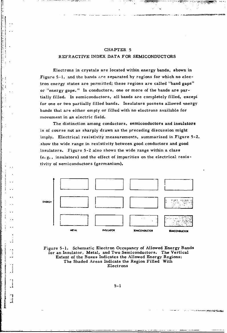
Electrons in crystals are located within energy bands, shown in
Figure 5-1, and the bands are separated by regions for which no elec-
tron energy states are permitted; these regions are called "band gaps"
or "energy gaps." In conductors, one or more of the bands are par-
tially filled. In semiconductors, all bands are completely filled, except
for one or two partially filled bands. Insulators possess allowed energy
bands that are either empty or filled with no electrons available for
movement in an electric field.
The distinction among conductors, semiconductors and insulators
is of course not as sharply drawn as the preceding discussion might
imply. Electrical resistivity measurements, summarized in Figure 5-2,
show the wide range in resistivity between good conductors and good
insulators. Figure 5-2 also shows the wide range within a class
(e. g., insulators) and the effect of impurities on the electrical resis-
tivity of semiconductors (germanium).
ENERGY
AAETAL INSULATOR SEMICONOUCTOR SEMICONOUCTOR
Figure 5-1. Schematic Electron Occupancy of Allowed Energy Bandsfor an Insulator, Metal, and Two Semiconductors. The Vertical
Extent of the Boxes Indicates the Allowed Energy Regions;The Shaded Areas Indicate the Region Filled With
Electrons
5-1
A

POLYSTYRENE tlS~1022
MICA, HARD GLASS I 1012
SOFT GLASS I°
DISTILLED WATER 1066
INTRINSIC SIUICON-
F- 104
-SEMICONDCTORS 102
INTRINSIC GERMANIUM
IAIPURIE GERMVANIUM l-
NICHROE - 1-4
PLATU IM L ODUTORSCOPPER CN
SILVER10-8
I-
Figure 5-2. Electrical Resistivity of Materials
5-Z
2I
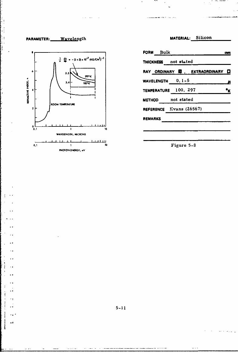
SILICON
INTRODUCTION
Silicon is a semiconductor that has found application in infrared
optics, transistors, diodes, rectifiers, solar cells, alloys and as
Hi deoxidizer in steels. Silicon is the second most abundant element,
usually occurring as oxide or silicate. Recovery from the oxide is
accomplished by reduction with carbon. Purification is accomplished
by distillation of silicon tetrachloride with subsequent reduction of the
tetrachloride with zinc. Zone melting with solidification and growth
of single crystals from the molten state provide further purification.
Highly purified silicon has a resistivity of approximately 2.5 x 10⁵ ohm-cm.
The physical properties of intrinsic silicon were summarized in
Table 1-1. Impurilies in silicon have an effect on a number of proper-
ties including electrical resistivity and optical transmission. It is
therefore important to realize that differences in optical data of several
authors may arise from different doping level; frequently, doping levels
-I are not stated in publications. Doping levels are often expressed in
I •terms of room temperature resistivity and Figure 5-3 provides the cor-
*. relation between electrical resistivity and impurity concentration at
300°K. The optical transmission of silicon is summarized in Figure 1-2.
DATA
All data presentations for silicon are listed in Tatle 5-1 and a sum-
mary of wavelength and temperature coverage is plotted in Figure 5-4.
Most data for bulk silicon are believed to have been obtained from single
crystal r.aterial, but experimenters have frequently failed to state the"I crystalline status of their specimens. Figures 5-5 to 5-14 and Tables
5-2 to 5-4 present refractive index data for bulk silicon for wavelengths
from the visible region to 200 microns; Figure 5-15 shows the extinction
coefficient for bulk silicon from 1. 0 to 15 microns. The effect of the" ~type of detector on the measured refractive index is evident from Fig-
ure 5-9. Figures 5-10 to 5-15 show data for doped sp!cimens. Fig-
ures 5-14 and 5-15 present the optical properties of a highly doped
I 5-5

-,- • • . • •.•.• . . . . - -- - -- - -•.• ..
p-type surface on an n-type substrate, wher- the doped layer is
considered to be semi-infinite; the effect of surface condition on the
refractive index is also apparent from these Figures (see also Figures
5-23 and 5-29). Finally, Figure 5-16 shows the influence of wavelength
on the refractive index of a silicon film. The effect of ter. perature on
the refractive index is the subject of Figures 5-17 to 5-26 for temper-
atures between 77 and 960*K.
Intrinsic silicon shows good agreement in refractive ir.dex data
and no large difference in refractive index is observable between bulk
and films. No significant differeaxce is detected between intrinsic bulk,
single crystal and polycrystalline refractive indices. Doped materials do
not exhibit a significant correlation between type and degree of doping,
and refractive index.
5-4
I !-- -~~-

I,
io
101
IJ
.~ ~P4TVPE
Mii : ,o-'I n-IYP F
10 .2
10"-
10- 1°"3
'1 1O0 , I , I , • •I
1 1014 10is 1016 1017 1018 101 9
1020 1021
IMPURITY CONCENTRATION, CM"3
Figure 5-3. Resistivity at 300°K versus Impurity Concentrationin Silicon [Irvin, (5250)]
TF Iwo2
11
Figure 5-4. Wavelength and Temperature Range of Silicon Data
S-

I_
Table 5-1. List of Silicon Data
WavelengthRange
(microns)Figure Table n or k Form Crystal From To Remarks Par;meter
59 C
5-5 5-4 n Bulk 1.4 11 Wavelength
5-6 n Bulk Single 0.25 1 Wavelength
5-3 n Bulk Single 1O0 Z6 zWavelength
5-7 n Bulk Single 1.1 4. 1 Wavelength
5-35 n Bulk 3 0.51 5 100. tre7tK Wavelength
5-9 n Bulk 10.03 I Wavelength
5-4 n Bulk "-1.0 2.6 b5. 300*K Wavelength
5-10 n Bulk 15 150 n-type Wavelength
5 - :,I n Bulk Z5 180 p-type Wavelength
53- 1 n Bulk Poly 4 I z Wavelength
5-1I3 n Bulk 3.5' 8. 5 ,v•c. treated Wavelength
5-14 n Bulk I is1 p-type Wavelength
5-153 k Bulk I 1 i1s p-typc Wavelength
5-16 n Film Poly 0.55 Z. 2 Wavelength
5-17 dn/dT Bulk Single 1.3 1.6 p-type. Temperature109-750"K
5-16 An Bulk 1.0 4.5 remperature
5-19 an/n Bulk, Single. 3.0 3.0 77--!UO0K TemperatureFilm c
-5-30 n Bulk 4 1.1 4.8 100-297 Temperature
5-1!1 n Bulk 1.3 5.2 p-type, Temperature109-750"K
i-2 n Bulk 0.9 2.0 p-type. TemperatureZbo-q6o'K
5-43 n Bulk 25 180 n-type. Temperature85-300"K
"5-24 n Bulk 0. 1 5.0 100 - 297"K Temperature
5-25 n Bulk 0.9 Z. 0 n -type. TemperatureZ80-960"K
-- 26 dnldT Bulk 0.45 2.0 n-type. Temperature280-960'K
5-Z7 n Bulk 0.1 5.0 Pressure
5-28 n Bulk 1 p-type Surface
5_0 k Bulk J I p-type Surface
Not stated.
PRECEDING PAGE BLANK
5-7

PARAMETER: Wavelength MATFRIAL: Silicon
3.510 FORM Bulk mm
THICKNESS NA (Prism)
S3.4w RAY ORDINARY"U, EXTRAORDINARY 0
WAVELENGTH 1.4-11S3.470
TEMPERATURE 299 0 K
3ý450 METHOD Deviation
REFERENCE Salzberg & Villa (3900)
3•3 - REMARKS
3.410 .-- • '-
2 4 6 2 10
WAVELENGTH, MICRONS
Figure 5-5
Ref rative%aelength. frdex,
1.3570 3.407S
I '3675 3.4462
1. 3951 3.4929)
I' szq3 3.4795
1. 6606 3. 439
1.7092 3.4637b
t.1326 1.•4476 Table 5-2Z.3254 3. 4130
2.4373 3. 440b
Z. 7144 3.4359
)1.00 3.4 2O
3. 3033 3 4207
3.4195 1.4Z86
3.50 3. 4284
4.00 3.4255
4.258 3.424Z
4.50 3.4216
5.00 3. 423
5.50 3.4Z13
6.00 3.420Z
6.30 3.4195
7.00 3.4189
7.50 3.4186
8.00 3.4184
8.50 3.412
10.G0 3.4179
10.30 3.41 78
5-8

PARAMETER: Wavelength MAT EiAL: Siii'zon
FORM Bulk, Single Crystal
s THICKNESS not stated mm
RAY ORDINARY U. EXTRAORDINARY 06
WAVELENGTH 0.1-5 1
TEMPERATURE 300 °K
MEl HOD Reflection2
REFERENCE Philipp & Taft (5951)
0 2 4 6 10 REMARKS Values above 1. 0 micron werePHOTON ENERGY, ev
taken from Salzberg & Villa (3900).
1.24 0.41 0.25 0.18 0.14
WAVLENGTH. MCRONS
Figure 5-6
THICKNESS 0. 5 - 2. 0 mm
RAY ORDINARY U. EXTRAORDINARY 0
"Wavelength Refractive Index,
(Microns) n WAVELENGTH 2-6-200
TEMPERATURE Z97 OK""26 -29 3.41*±0,.03
METHOD Interference111-200 3.41 * 0.03
REFERENCE Aronson, et al. (16091)
REMARKS Crystal cut perpendicular
to the [111] axis.
Table 5-3
15-9
1[1T

PARAMETER: Wavelenpth MATERIAL: Silicon
FORM Single Crystal Prism
3.5A0
THICKNESS NA mm
C
i 3.40 RAY ORDINARYE. EXTRAORDINARY 0
WAVELENGTH 1.1-4.83.40297"1K
0• . TEMPERATURE 100-Z97 K
3.40 METHOD Deviation
I . 3 . REFERENCE Cardona, et al. (620)1.0 2.0 3.0 4.0 5.0
WAWVUNGTH, MKIONS REMARKS ______________
Figure 5-7
5-10
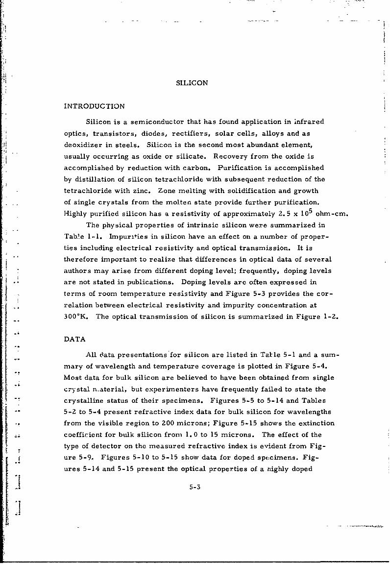
PARAMETER: Wavelength MATERIAL: Silicon
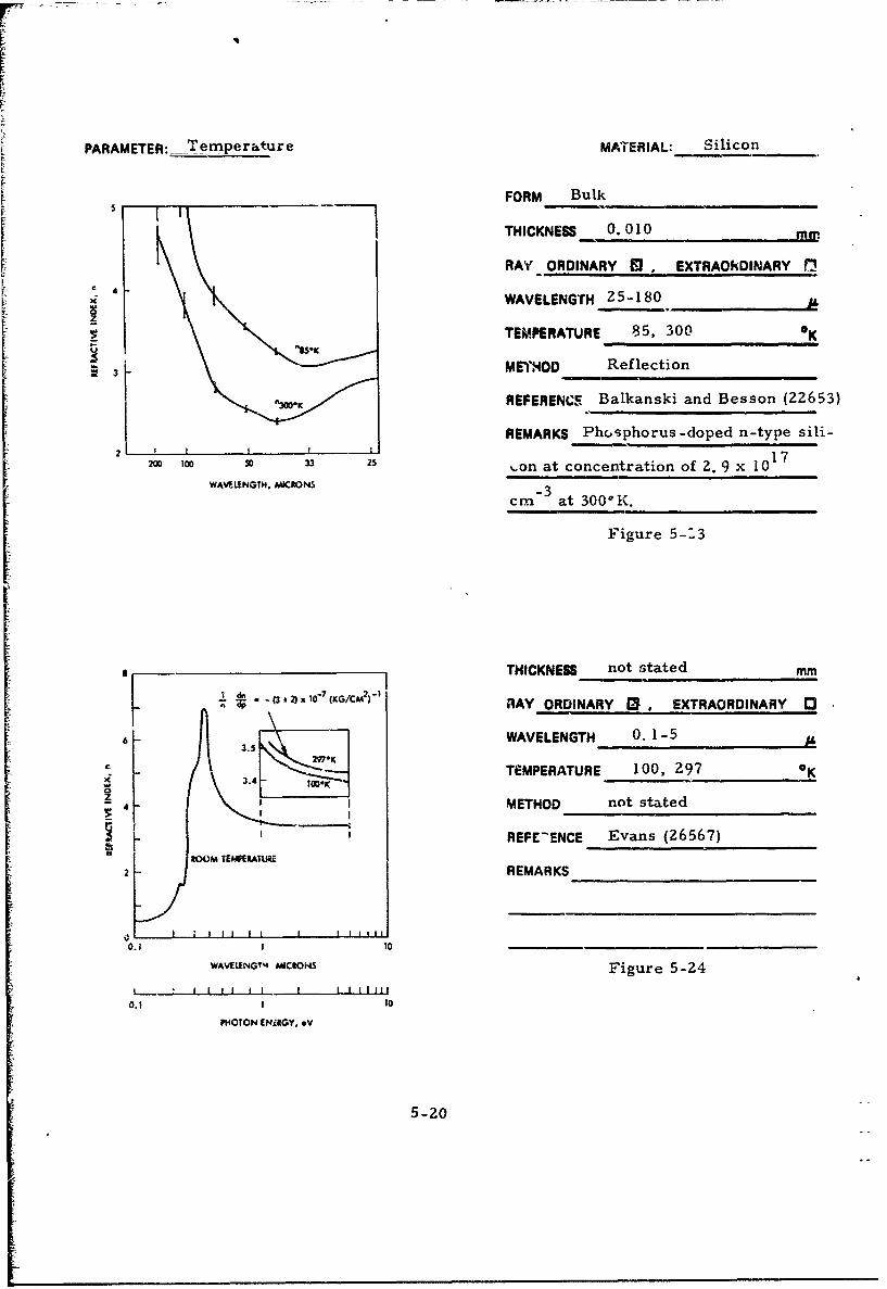
FORM Bulk mm\ (KG/CM-) THICKNESS not stated
k 3.5 RAY ORDINARY U. EXTRAORDINARY 0
3.j4- 10"K ,.WAVELENGTH 0.1-5
TEMPERATURE 100, 297 *K
METHOD not statedROOM TMPEIRATUKE
2 REFERENCE Evans (26567)
REMARKS
0 IIU 1110.1 I 10
WAVELENGTH. MICRONS
0.1 1 10 Figure 5-8PHOTON ENERGY, eV
"• ~5-11

PARAMETER:" Wavelength MATERIAL: Silicon
____________FORM Bulk3.440
THICKNESS NA (Prism) mma STANQANDSI~ DOfOI GO DETECTOR
OTNERMOCOfU DETECTOR RAY ORDINARY . EXTRAORDINARY r33.435
WAVELENGTH 0.03-12
TEMPERATURE -298 0K
S3.40 METHOD Deviation
REFERENCE Hilton, et al. , (25628)
3.425 REMARKS
a
Fgr 5-9
3.4%4 6 S 10 12
WAVEUNGTHo MICRONS
THICKNESS NA (Prism) mmWavelength, Refractive Index,(Microns) n RAY ORDINARY 19. EXTRAORDINARY 0
1.05 3.565 WAVELENGTH 1.0-2.6 i
1.10 3.553 TEMPERATURE -298 OK
1. 20 HO : ,D Deviation
L.40 3.499REFERENCE Briggs (13314)
1. 60 3. 480
1.80 3.466 RFMARKS
2.00 3.458
2.20 3.451
2.40 3.4472. 2' 3. 443 Table 5-4
5-12

~A~AM~TER: V ~~IL~b&LMATIERIAL:_______
FORM Bulkr THICKNESS 0.010 mm
RAY ORDINARY B . EXTRAORDINARY 01
IC WAVELENGTH 25-180
TEMPERATURE 85, 300 *K
3 METHOD Reflection
"REFERENCE Balkanski & Besson (22653)
2. REMARKS Phosphorus-doped n-type
20 100 33 25 silicon at concentration of 2. 9 x 10¹⁷WAVELENGTH, MICRONS
-3cm at 3000 K.
Figure 5-10
THICKNESS 0.010 mm
RAY ORDINARY U, EXTRAORDINARY (3
WAVELENGTH 2-5-180 p
TEMPERATURE 300 OK
METHOD RefLeczlon
3 sREFERENCE Balkanski & Besson (22653)
REMARKS Arsenic-doped p-type silicon
18 -3with concentration of 1.7 x 10 cm
200 I00 o 33 1at 3000 K.
WAVELENGTH, MICRONS
I.I I I I1 Figure 5-110 100 200 300 40J
"WAVE NUMBWER, CMA
5-13
*1

SPARAMETER: Wayetength MATERIAL: Silicon
FORM Bulk, polycrystalline
3m
THICKNESS not stated mmT
2: RAY ORDINARY U . EXTRAORDINARY 0
WAVELENGTH 4-12Ii
TEMPERATURE -298 eK
I METHOD Reflection6W lOw 1400 1000 220=
WAVE .UJUR, CM"C REFERENCE Simon (4799)ira i I Ii I I I I II
14 10 S 6 4 REMARKS Resistivity = 0. 7 ohm-cmWAVELENGTH. MICRONS
Figure 5-12
0.2
3.0- I CURVE 0(EC)
0 2 0 THICKNESS not stated mm0.8 03 60
£4 9 RAY OFRDINARY A , EXTRAORDINARY C30.60a 5 120 & 210o.6-1
WAVELENGTH 3.5-8.5
S0.4 TEMPERATURE -"-298 OK
x
0.2 METHOD Reflection
2.0 - REFERENCE Spitzer, et al., (13860)
REMARKS Phosphorus-doped n-type
silicon with concentration at 298 K1.6
of 7. 5 x 10s7 cm-3. Material vacuum-1.4 - heat treated at 13100K.
. Figure 5-13
1.0 I I i3 5 M R
WAVELENGTH, MIdCRONS"
5-14

Li
PARAMETER: Wavelengh MATERIAL: Silicon
3.0 FORM p-type s,,riace on n-type substrate
THICKNESS 1 x 10 (p-type) mm
RAY ORDINARY O EXTRAORDINARY 0
ý.o ,WAVELENGTH 1-15
, ,9,1, , 15 ITEMPERATURE '-298 OK1 3 5 7 9 11 13 15 -
WAVELENGTH, MICRONS METHOD R efle ction
REFERENCE Hall (13466)
REMARKS p-type surface produced by
"doping with boron.
"Figure 5-14
Figure 5-15
* ~3.0 1
Z-. u 2.5IN•J 2.0 -DULL
- " • 1.0-
-- -- 0.5 -
- " I 3 5 7 9 II 13 15
WAVELENGTH, MICRONS
5-15

PARAMETER: Wavelength MATERIAL: Silicon
FORM Film, amorphous
4.4 THICKNESS (0. 4-3. 25) x 10- mm
4.2 -- RAY ORDINARY M. EXTRAORDINARY 13
4.0- WAVELENGTH 0. 55-2. 23.8 TEMPERATURE 298 0
3.6 METHOD
3.4 I I I I ! I a a ! |
0.6 0 .0 1.2 1.4 1.6 .8 2.0 2.2 2.4 REFERENCE Grigorovici & Vancu (35455)
M4OTONIENERGY, eV REMARKS Film produced byI I I I I I I I I I
2.07 1.24 0.89 0.69 0.56 evaporation of pure silicon singleWAVELENGTH, MICRONS
*CRYSTAL DATA CALCULATZID FROM RE (194) crystal (resistivity = 10 ohm-cm) at
"<1 x 10- torr using electronbombardment and lower end of silicon
pdww*ag-.qh. ,i.e as crucible.
ftwio.ig Coop" Note: crystal data refer to single
crystals.
Figure 5-16
5-16

PARAMETER: Ternerature MATERIAL: Silicon
3 FORM Single Crystal
1. 56p .THICKNESS NA (Prism) mmIT
2 RAY ORDINARY EXTRAORDINARY 03
WAVELENGTH 1.26-1.56
TEMPERATURE 109-750 0K
METHOD Deviation
REFERENCE Lukes (3382)
2oo RATURo oREMARKS p-type silicon,TEMi•RATUIE, 'K
resistivity = 380 ohm-cm.
Cepyright 1959 porgeOo Pros
Figure 5-17
THICKNESS NA (Prism) mm-" :R 0.10
" "-• RAY ORDINARY • EXTRAORDINARY 0 3
-O0.05 WAVELENGTH 1.0-4.5
,•i '.--Zt . : L TEMPERATURE 87, 2-97 OK
0_2 - METHOD DeviationCl ~~WAVELENGTH, MICRONS TMEAUE____________
REFERLNCE Cardona (2569)
3REMARKS
Figure 5-18
5-17

PARAMETER: Temperature MATERIAL:- ii
3 •FORM Single CrystaL Fiii ý- P-isry,
c =LS THICKNESS Film 0. 003-01010 mma a MiSms
RAY ORDNARY I . EXTRAORDINARY 1
10 WAVELENGTH 3.0
TEMPERATURE 77- 4C0 OK
_ __ METHOD Interference for films,
0 1 2000 deviation for prism.T1E.iATUE. *K REFERENCE Cardona, et al. (620)
REMARKS
Equation:
(1/n)(dn/dT) ; (3.9 * 0.4) x 10 K) Figure 5-19
THICKNESS NA (Prism) mm
3.M0 RAY ORDINARY [3 EXTRAORDINARY 0
x WAVELENGTH 1.1-4.8
z TEMPERATURE 100-297 0 K
3.4o M,*K METHOD Deviation
3.• . REFERENCE Cardona, et al. (620)
[ ---- u-•. i REMARKS1.0 2.0 3.0 40 5.0
WAVEINGiH, MCRONS ____________________
Figure 5-20
",'e I"I 58959 I o Pipes*
5-18

"1MOAA
PAAETR x Cal ~ fica~maSiico
3.60* FORM Bulk
0.5~ THICKNESS NA (Prism) mm
3.5 l4Op, ~AA ORDINARY M EXTRAORDINARY 130 0F 1 6l WAVELENGTH 1. 3-5.2
0.adp 0249 TEMPERATURE 109-70*
- do,, 4, 004 .16 METHOD D~eviation
0 ov 00909OdleREFERENCE Lukes (4541)
oe oe 00REMARKS p-type silicon,
I' " " Resistivity = 380 ohm-cm.100 3005 7
TEI*EATURE. -K ___________________
F igure 5-21
capw96o a.*mbva
6 00- - THICKNESS 1. 77 (Bulk) mm
*kRAY ORDINARY 13 EXTRAORDINARY 03
5.00 L TEMPERATURE 280-960 O
0METHOD ]Emissivity4.0z
U REFERENCE Sato (29333)AL- 09p
4.0-111---J- REMARKS n-type silicon, p-doped,f, resistivity = 15 ohm-cm.
3.001 Figure 5-22I200 400 600 goo lowTEhVUATURE, -K
5-19
PARAMETER: Temperature MATERIAL: Silicon
FORM Bulk
I THICKNESS 0.010 m
RAY ORDINARY • , EXTRAOkDINARY t•
WAVELENGTH 25-180
TEMPERATURE 85, 300 *K
V METHOD Reflection
"REFERENCE Balkanski and Besson (22653)
REMARKS Phosphorus-doped n-type sili-
2o ,® 0 33 25 %on at concentration of 2. 9 x 10¹⁷
WAVELENGTH, MICIONS -3 acm at 3000 K.
Figure 5-.3
I THICKNESS not stated mm7 - - Oo 7(G/CM 2 " IAY ORDINARY [ , EXTRAORDINARY 13
6 WAVELENGTH 0.1-5 A
63.5
3.4 TEMPERATURE 100, 297 •K£6' .4-_ ____ ____ ___
j 4 IMETHOD not stated
REFE-ENCE Evans (26567)ROOM TERATUIR__
2 - REMARKS
0} 1 % I ! I I ! ! I I I I I11 1 10.1 1 10
WAVELENG•14 CROS Figure 5-24L .. iI I I I Figure 5-24l
o.I I l0
PHOTON ENiRGY, eV
5-20

[IPARAMETErR: Temperature MATERIAL: Silicon
600 FORM Bulk
U IICKNESS 1.77 MM5.50-
RAY ORDINARY B.EXTRAORDINARY 13
5.0 WAVELENGTH 0.9 -2.0 A
.TEMPERATURE 280 - 960
~4.50 _ _ _ _ _ _ _
METHOD Emis sivity-::-k 0L 9O0J
4.00 -REFERENCE Sato (29333)
- 350 ~ A. C0 1REMARKS n-type silicon, phosphorus-
3-50 00,doped, resistivity = 15 Q -cm.
20D 400 611 ew wo_ _ _ _ __ _ _ _ _ _ _
TEA*EWIAUE, - Figure 5-25
*:Calculated fron-
Ernissivity 4 2(n + 1
7~ Figure 5-26
1 0 4 3~[ IFACIV~INtX
11ZjAU2

r
PARAMETER: Pressure MATERIAL: Silicon
I".FORM BulkI * -3 2)1 -7 (KG M 1
TITHIKNES, not stated mm
3.5 RAY ORDINARY Q. EXTRAORDINARY 0
3z 4 WAVELENGTH 0. 1-5.0
4TEMPERATURE 297 K
RO METHOD not statedROOM TEAPEIATU6E_________ _______
2 REFERENCE Evans (26567)
"REMARKS0 I I I I iI .II l
0.1 1 10
WAVELENGTH, M011CROKS
S I I I I I I I I II III1_____________________________
P0.OTON to.v Figure 5-27
5-22

V[MATE~iiAL; ieo- ~PARAM ETER: eition N T ~ A ; S i e n _,
FORM p-type surface on n-type substrate
3.0
THICKNESS I x 10- (p-ty film: mM
z 2.0o- RAY ORDINARY 13 EXTRAORDINARY
DULL WAVELENGTH 1-151.0 SIY9 _ _ _ _ _ _ _ _ _ _
S0.5 TEMPERATURE -298 0K
I | | I I I ! I I I | I I
1 3 5 7 9 11 13 15 METHOD R~eflectionWAL NGTIH, AMICRONS
REFERENCE H-aall
REMARKS p-type surface produc~f- by
doping with boron.
Figure 5-28
30
Z 2.5
0 15 SHN Figure 5-29z2 Z .
"" 0.5
1 3 S 7 9 I1 13 15
WAWILENGl4, MICRONS
5-23

I.
GERMANIUM
INTRODUCTION
Germanium is a semiconductor that has found apilcation in
infrared optics, transistors, diodes, rectifiers, thermoelectric
devices and in brazing alloys. Recovery of germanium from. ores
involves a series of steps including pyro and hydrornetalhrgy to pro-
duce a germanium concentrate, chlorination to obtain a purer german-
ium tetrachloride, hydrolysis to produce still purer germanium dioxide
and reduction of the oxide to the rr.-•al with zinc. This "first reduction
metal" is zone refined to produce semiconductor grade germanium,
and an increase in resistivity is accomplished from a minimum of
- 5 ohm-cm. for first reduction metal to a minimum of 40 ohm-cm. for
the zone-refined metal. The resistivity of intrinsic germanium is 47 ohm-cm.
The phyrical properties of intrisic germanium are summarized
in Table 1-1, and its optical transmission spectrum is plotted in
Figure 1-3. Impurities in germanium have an effect on several pro-
perties including electrical resistivrity and optical transmission.
Indeed, even films prepared by evaporation of highly purified intrinsic
germanium have shown to be p-type germanium with a resistivity of
3 to 10 ohm-cm, [Ref: Courvoisier, [1963]] . It is therefore apparent
Sthat a comparison of optical properties of evaporated films, measured
by various workers, may be unrealistic because of different doping
j levels.
Doping levels are oiten expressed in terms of room temperature
resistivity and Figure 5-30 permits the conversion between electrical
resistivity and impurity concentration, at 300*K.
DATA
All data presentations for germanium are listed in Table 5-5 and
a summary of wavelength and temperature coverage is plotted in
Figure 5-31.
Figure 5-32 presents a comparison in refractive indices of bulk
and film germanium and also provides an introductory presentation ofPRECEDING PAGE BLANK
5-25

i02
101
1--1
0I0°1
10 -2 p - G *
10-3
IO-4
1014 1015 1016 10'7 1018 1019 1020 1021
IMIURITY CONCENTRATION, CM"3
Figure 5-30. Resistivity versus ImpurityConcentration for Ge, 300"K
Ref: Sze and Irvin (34530)
the effect of the nature of the evaporation atmosphere during film
deposition. Data in Figure 5-32 as well as subsequent Figures show
a consistently higher refractive index for films as compared to bulk
germanium. Some observers [Ref: Wales, et al. (31497)] believe that
this difference is caused by the presence of at least one additional loosely
bonded electron than normal at the surface of the crystallites. German-
ium films, deposited onto substrates that are below 673°K, are amor-
phous and will atsume the refractive index of bulk material after
annealing; annealing of such films caused crystallite formation.
Similarly, deposition onto heated substrates (>673°K) resulted in the
formation of films having bulk refracfive index. Figures 5-33 to 5-48
and Tables 5-6 to 5-10 present additional spectral data for the refrac-
tive index of bulk and film germanium. As was the case with silicon,
no generalization is possible for the effect of doping on the refractive
5-26

Table 5-5. List of Germanium Data
Wavelength
(microns)
Figure Table n or k Form Crystal From To Remarks Parameter
5-32 n Bulk, 1.0 6.0 Data comparison Wavelength
Film
5-33 n Bulk Single 0.6 1.7 3(00K Wavelength
5-34 n Bulk Single 0.6 1.7 120"K Wavelength
5-35 n B,%lk Single 2 16 Wavelength
5-36 n Bulk 1.5 13 Wavelength
5-37 n Bulk Single 0.6 5.5 87-297"K Wavelength
5-38 n Bulk 0.8 5.5 Several doping Wvelengthlevelb
5-39 n Bn1k Single 0. I 1.8 Wavelength
5-6 n Bl3dk Single 25 143 7.5. 297"K Wavelength
5-40 n Bulk Single 0.8 15 Wavelength
5-7 n Bulk Single 1.0 2.4 Wavelength
5-41 n Bulk 70 ;00 Wavelength
5-8 n Bulk Single, polycryst z l I Wavelength
5-9 n Bulk I.0 2. Wavelength
5-42 n Bulk 4 14 . Wavelength
5-43 n Bulk 5 35 n-doped, p-dcped Wavelength
5-44 k Bulk 12 35 n-noped Wavelenith
5-10 n Filrn 8.7 12.4 77. 300'K Wavelength
5-45 n Film 1.0 5.0 Wavelength
5-46 n Film 0.6 10 Wavelength
5-47 n Film Polycryst 0.7 3.1 p-doped Wavelength
5-48 n Film 0.?$5 2.5 Wivelength
5-qn Bulk Single 1.8 5.5 n-doped Temperature
5-50 n Bulk 2. g Z. 5 n-doped Temperature
5-51 dn/dT Bulk 2. 2.5 n doe Temperature
5-5i Bulk Single I. 5 2.2 80-4b0'K emperature
5-11 n Bulk Z 3 143 7. 5, 297'K [Temperature
Not stated.
5-Z7

Table 5-5 (continued)
Wavelength
Range(microns)
Figure Table nor k Form Crystal From To Remarks Par'meter
5-53 n Bulk Single 0.6 1.7 300"K Temperatuce
5-54 n Bulk Single 0.6 1.7 120"K Temperature
5.55 n Bulk 1.8 5.3 87-297'K Temperature
5-56 An/n Bulk, C 3.0 3.0 90-400'K Ten.oeratureFilm
5-12 dn/dT C 2.25 2.25 Temperature
5-13 n Bulk Single 2.0 2. 4 1 emperature
5-14 n Film C 8.7 12.4 77-300"K Temperature
1-57 An/n Film C 2.0 4.0 77-395"K Temperature
5-15 (0l/ndn/dp Film C 3.0 3.0 Pressure
5-16 (l/nldn/dp Film C 3 3 From RI, dielec- Pressuretric data
5-17 (l/n)'n/dp Film 5 2.0 4.0 Presure
5.18 n Film C 2.64 2.64 0.07-6.51, Film ThicknessThickness
5-58 n Film - 2.2 2.2 Ge/Znb Film Film Composition
5-59 n Film C 1.0 5.0 Film DepositionRate
5-60 n Film C 1.0 5.0 Air atmosphere Atmosphere FilmDeposition
5-61 n Film C 0.5 5.0 Vacuum Atmosphere Filmatmosphere Deposition
•-2n Fm .0 5. xgnAtmosphere Film
i atmosphere Deposition
5-63 n Film C 1.0 5.0 Nitrogen Atmosphere Filmatmosphere Deposition5-64 n Film 5 1.0 5.0 Nitrogen Atmosphere Film
atmosphere Deposition
5-6r4 n Film a 1.0 5.0 itydogen Atmosphere Filmatmosphere Deposition
5-66 n Ftlm 5 1.0 5.0 273%o Deposition Fub-strate D emperaturep
5-67 n Film C 1.0 5,0 3 4743v, Deposition Sub-strate Tempezature
5-68 n Film 5 1.0 5.0 673"K Deposition Sub-strate Temperature
5-69 n Film 1.0 5.0 773- K Deposition Sub-strate Temperature
5-70 n Film Amorphous and 1.25 6.5 293-573-K Deposition SEb-polycryst. strate Temper.ture
5-71 An Bulk 4 1.6 2 2 Electric Field
*Not stated.
5-28
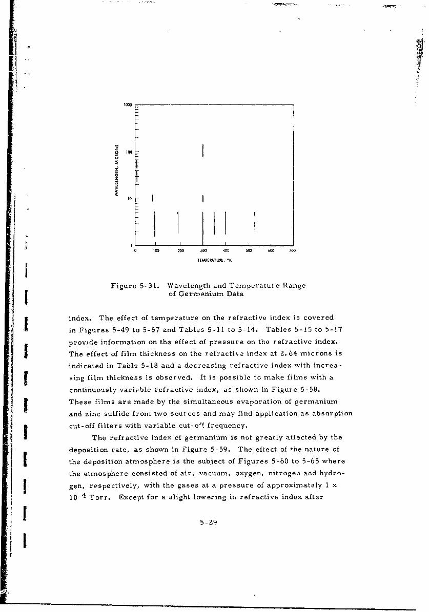
Ii,'
10
I 1
0 100 200 300 400 500 600 700
TEMPERATUXk, 'K
Figure 5-31. Wavelength and Temperature Rangeof Germanium Data
index. The effect of temperature on the refractive index is covered
in Figures 5-49 to 5-57 and Tables 5-11 to 5-14. Tables 5-15 to 5-17
provide information on the effect of pressure on the refractive index.
The effect of film thickness on the refractive index at 2.64 microns is
indicated in Table 5-18 and a decreasing refractive index with increa-
sing film thickness is observed. It is possible to make films with a
continuously variable refractive index, as shown in Figure 5-58.
These films are made by the simultaneous evaporation of germanium
and zinc sulfide from two sources and may find application as absorption
cut-off filters with variable cut-o'f frequency.
The refractive index ef germanium is not greatly affected by the
deposition rate, as shown in Figure 5-59. The eflect of the nature of
II the deposition atmosphere is the subject of Figures 5-60 to 5-65 where
the atmosphere consisted of air, ,acuum, oxygen, nitrogea and hydr,-
gen, respectively, with the gases at a pressure of approximately I x
10-4 Torr. Except for a slight lowering in refractive index after
ii 5-29
1'

deposition in oxygen, no significant effect was obsarved. The low
index from deposition in an oxygen environment may be caused by the
formation of germanium dioxide, having a refractive index of approxi-
mately two in the near-infrared.
The substrate temperature during deposition has an effect on the
crystallinity of the film. According to Davey [1961] , germanium films
which are deposited at a substrate temperature below 448*K, are
amorphous. Data by Wales, et al. (31497) indicate a lower refractive
index for films, deposited on hot substrates, (Figure 5-66 to 5-69).
This is in contrast to the results of Gisin and Ivano-, (41222), Fig-
ure 5-70, who obtained a higher refractive index for substrates at
523 - 5730 K than at 403 -4230 K, their refractive indices for 403-423° K
and 293 - 3030K were nearly identical, indicative of an amzorphous state
at both lower temperature ranges.
The dependence of the refractive index on the electric field is
illustrated in Figure 5-71 in a study of the Franz-Keldysh Effect.
5-30
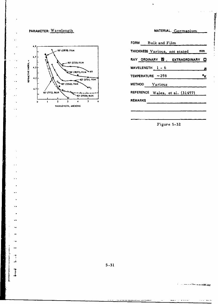
PARAMETER: Wavelength MATERIAL. Germanium
4.9'FORM Bulk and Film
4.7
REF 2298): ILMTHICKNESS Various, not stated mm47 -RAY ORDINARY U , EXTRAORDINARY 03
RE 37•$13:
FILM
..
4.5 - E r, MARWAVELENGTH I - 6
34.3 TEMPERATURE '-298 0K
t Q-~ 133;FILM METHOD Various
REF (7113), SULK \REFERENCE Wales, et al. (31497)
2, 3 R E M A R K S
WAVELENGTH, MICRON$S
Figure 5-3Z
5-31

PARAMETER: Wavelength MATERIAL: Germanium
6.0
FORM Bulk, Single Crystal
THICKNESS Not stated mm
5.5 RAY ORDINARY f, EXTRAORDINARY 1'3
SWAVELENGTH 0.6 - 1.7 AL
TEMPERATURE 120, 300 0K
METHOD Reflection
REFERENCE Potter (27255)
4.5 REMARKS
4.0- Figure 5-330.5 1.0 1.5 2.0 (300 0 K)
PHOTON [E,4GY. ,V
I I I I2.4 1.24 0.3 0.62
WAWLENGTHI, MJCONS
6.0
5.5 Figure 5-34
(120 0 K)
5.0
4.5
: ~4.0II0.5 1.0 1.5 2.0
PHOTON INEEGY, eV
2.4 1.24 O.83 0.62t
WAVELNGII, Mk IONS
5-32

K F
PARAMETER: Wavelength MATERIAL: eriii•nu ,
FORM Bulk, Single Crystal
4.100 THICKNESS NA (Prism) mm
RAY ORDINARY E EXTRAORDINARY C34.M6
WAVELENGTH 2 - 16 ..... _,_
C'. TEMPERATURE 300 KS4.03o
METHOD Deviation
REFERENCE Salzberg and Villa (3900)"' • ~4.00 '-
I REMARKS
4.020
0"4.000 Figure 3-350 4 8 12 16
WAVEL•NGTH, MICRONS
THICKNESS- NA (Prism) mm
CIRCUSsFROM RAY ORDINARY U, E)'TPAORD!NARY 03S RF$ 39254 . .
x UR 14254 WAVELENGTH 1.5 13"17 7
TEMPERATURE 291 OK
METHOD Deviation
16I REMARKS Resistivity = 50 ohm-cm0 0.2 0.4 5.6 08REFERENCE Kornfeld (14254.)
12.4 3.1 1.5
WAVELENGTH, MICRONS
Figure 5-36
S~5-33
r• i , m . • . = . . ..
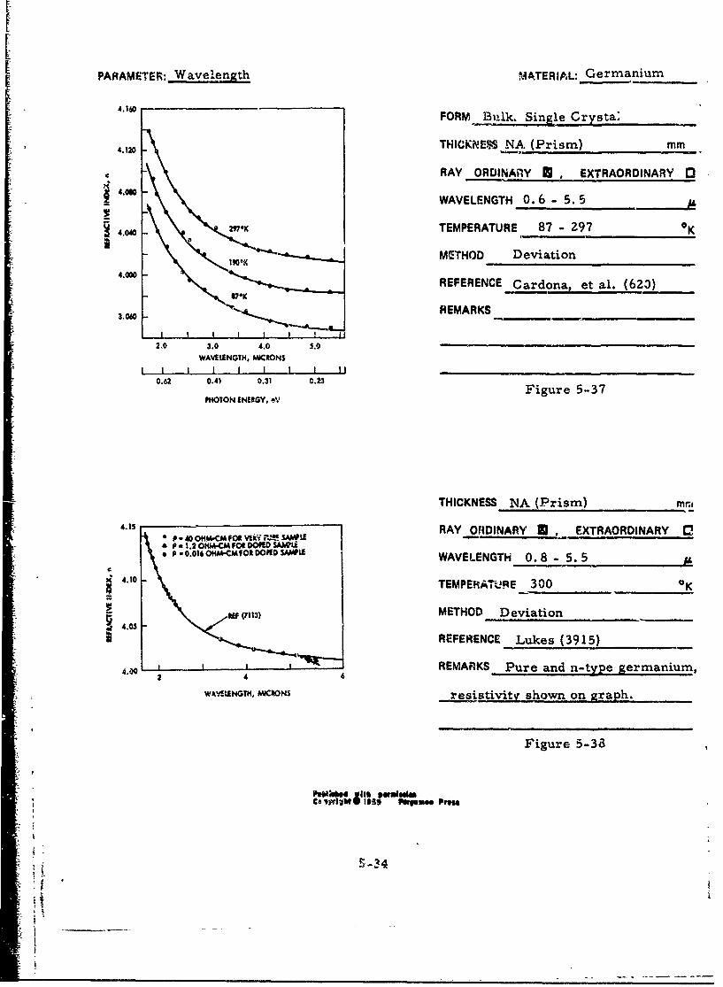
PA RAM ETER: W av ele n th M ATERIA L: G erm anium
4.160 FORM Bulk. Single Crysta;.
4.1 THICKNESS NA. (Prism) mm
RAY ORDINAnY 0 , EXTRAORDINARY [34.090 - WAVELENGTH 0.6 - 5.5
4.040 max TEMPERATURE 87 - 297 K
"MSTHOD Deviation
4.000 REFERENCE Cardona, et al. (623)
306 REMARKS
2.0 3.0 4.0 5.0WAVELENGTH, MQC*ON$I I I ,I I I I II
Figure 5-37PHOTON ENERGY, eV
T H I C K N E S S N A ( P r i s m ) m r ..
4.15 4 RAY ORDINARY , EXTRAORDINARY D,2 pw0"iMCMPOWX0 4 s1£ " 1.2OHM-CM FORIDOPED SAW L
P -.0.016OHNMCMFOR DOPE SAUILE WAVELENGTH 0.8 - 5.5
4.10 TEMPERATuJRE 300 OK
REF METHOD Deviation
REFERENCE Lukes (3915)
_ __. oi_, REMARKS Pure and n-type germ anium ,
WAyV!!NGTH, MICRONS resistivity shown on graph.
Figure 5-38
I-s4 ftrgsms Pm.
S.- 3
7 t

PARAMETER: Wavelength MATERiAL: rmaniurr-r
FORM Bulk, Single Crystal
6 THICKNESS Not stated mm
RAY ORDINARY * EXTPAORDINARY 04 _ _
3 - WAVELENGTH 0.1- 1.8
TEMPERATURE 300 0K
"",LJ.LL L._L_ iMETHOD ReficctionC, I 2 3 4 5 6 7 8 9 10
PHOTON ENERGY, eV REFEREN'SCE Philipp and Taft (7113)
6ý 0.41 •PMARKS Data above 1. 77 MicronsWAVEIINGfIH. MICRONS taken from Salzberg and Villa (3900).
Figure S-39
Wavelength, Temperature Refractive THICKNESS 0.=5 - 2 0 mm
(Microns) OK Index, n RAY ORDINARY , EXTRAORDINARY 0
23-40 7.5 3. 98 +0.02 WAVELENGTH 23 - 143 IL
45-67 7.5 3.90 ±0.02 TEMPERATURE 7.5, 297 *K
83-143 297 3.98 ±0.002 METHOD Interference
REFERENCE. Aronson, et al. (16091)
REMARKS Crystal cut perpendicular
-to the [IlII axis.
Table 5-6
5-35
1' 1

L
PARAMETER: Wavelenath MATERIAL: Germanium
FORM Bulk, Single CrystalTHICKNESS ,7. ..... mm
P AY ORDINARY M. EXTRAORDINARY 13
WAVELENGTH 0. 8- 15. 2S.04.0 TEMPERATURE •-297 0K
METHOD Transmission, Reflection
0 4 1 12 16 REFERENCE Oswald and Schade (2139)WAVRIENGTH, MICWN$ .. .
REMARKS Resistivity = 56 ohm-cm.
Figure 5-4C
THICKNESS 3.06 mmWavelength, Refractive
(Microns) Index, n RAY ORDINARY E EXTRAORDINARY E
2. j0 4.1254 WAVELENGTH 2.0 - 2.4
2 to 4.1145 "FhMPERATUEE 297.5 °K
.30 4. 0980 METHOD Interference
2.40 4.0918 REFERENCE Rank, et al. (39713)
REMARKS Measurements in vacuo.
Table 5-7
5-36

PARAMETER: Wavelength MATERiAL: Germanitiim
FORM Bulk
THICKNESS 1.89, 6.23 MI
0.0-,00eeo0ooo0000o,,00 ,,0 RAY ORDINARY M , EXTRAORDINARY "1
40040 00 00 00
"" 1.94 oICK 40 -CQ WAVELENGTH 70 - 50006 23MM THICK( lDfl-CM)
_. •000O. j J I I 1 TEMPERATURE -300 *K20 50 so 110 140
WAVr NUMUR, CM"1 METHOD Interference-,• lI -I I I
500 200 100 71 REFERENCE Randall and ltawcliffe (33Z51)WAVEIVNGTH. MICRONS
REMARKS Resiotivity:.
1. 94 m n. sam ie, 40 ohm-cm.
6. Z3 mm. sample, 10 ohm-cm.
Figure 5-41
5-37S1li
Ar

PARAMETER: Wavelength MATERIAL: Germanium
ýndex
Snfhe.crystal FORM BulkWe-lenglth n Polycrystla
1Mi4crnas) 1 - J n
Z.0181 4.1016 4.1016 4.101 " THICKNESS NA (Prism) inm2.15Z6 4.0917 4.0919 4.0919 RAY ORDINARY U EXTRAORDINtARY IU2. U126 4.0781 4.0786 4.078A
2.4174 4.0706 4.0708 4.0709 WAVELENGTH Z- 16Z.S77 4.0610 4.0609 4.0608
2.7144 4.0554 4.0SS2 4.0534 TEMPERATURE 300 OK
Z. 998 4.0453 4.0452 4.0452
3.30)3 4.0370 4.0369 4.037Z METHOD Deviation3.4188 4.0336 4.0334 4.0339
4.258 4.0217 4.OZ16 4.oZ17 REFERENCE Salzberg and Villa (39254)3.866 4.0170 4.01,0 4.0167
6.s.6 4.009Z 4.0094 4.009S REMARKS Single and polycrystalline8.66 4.0036 - -090 4.0043
9.7! 4.0016 4.0034 4.0033 material11.04 4.0010 4.0026 4.00ma
12.20 4.0018 4.00Z3 4.0020
13.02 4.0016 4.00Z1 4.0018
1411z 4.001o Table 5-815.08 4.0014
16.00 4.001Z
I p-eviously publiehed data from Saltberg and Villa (3900)
Wavelength Refractive THICKNESS NA (Prism) mm
(Microns) Index, n RAY ORDINARY U , EXTRAORDINARY 3
1.80 4.143 WAVELENGTH 1.8 - 2.61.85 4.135 TEMPERATURE -298 °K
1.90 4.1Z9 METHOD Deviation
2.00 4.116 REFERENCE Briggs (13314)
2.10 4.104 REMARKS_
2.20 4.092
2.30 4.085
2.40 4.078 Table 5-9
2.50 4.072
2.60 4.068
5-38

PARAMETER: Wavelength MATERIAL: Germaniumi
_FORM Bulk
4 THICKNESS -,0.8 mm
RAY ORDINARY r " EXTRAORDINARY 033
z zWAVELENGTH 4- 14
TEMPERATURE Not stated 0 K
METHOD Reflection
REFERENCE Simon (4799)o 1000 4m 1800 2-0 26i00 REMARKS n-type material withroo 1000 1400 1600) 2200 2600
WAVE NUMR, CM- 1 resistivity 1 ohm-cm at 297°K
14 12 10 8 6 5 4
WAVELENGTH, AMCRONSFigure 5-4'
I 53
I -~

PAFRAMETER: Wavelength MATERIAL: Germanium
FORM Bulk
4.0 -w.e-E THICKNESS -10"2 mm
4.0 : n's. RAY ORDINARY B, EXTRAORDINARY !1(r.-TY?E)\\
0 WAVELENGTH 5 - 35
S 3.0TEMPERATURE Z97 K
4 •METHOD Transmission, Reflection
L GERMANIUM t8
CM3 \ REFERENCE Spitzer and Fan (791)
2.0 N P-TYPE. N - 3.9 x 10 19 CM "3[ P -TYPE: N *1. 1 x 10~ M
I REMARKS n-type, arsenic-doped mate-s 10 15 2t, 25 rial, concentration = 3.9 xiO 18 cm3
WAVELENGTH, MICRONS
p-type, gallium-doped, concentration =
1.i x 1019 cm.1.0
Figure 5-43
0.5
THICKNESS -2 mm
RAY ORDINARY _ , EXTRAORDINARY 0
WAVELENGTH 1Z - 350.2 /
S1 TEMPERATURE Z97 OK
y METHOD Transmission, Reflection
0 0.1 REFERENCE Spitzer and Fan (791)z -,
REMARKS n-type, arsenic doped mate--• ; 39x118 -3
S0.05 rial, concentration = 3.9x.. cm
Figure 5-44
0.02
0.01 I I
10 20 50
WAVELENGTH, MICRONS 5-40

PARAMETER: Wavelength MATERIAL: Germanium
Refractive Index, FORM FilmW avelength, n
(Microns) THICKNESS 0.227 mm
77 0 K 300 0 K_......__ ,RAY ORDINARY M, EXTRAORDINARY 0
8.66 3.77 3.92 WAVELENGTH 8.66 - 12.35 '.
.1 9.4 3.81 3.90 TEMPERATURE 77, 300 0K
i 10.2 3.81 3.93 METHOD Interference
11.22 3.81 3.92 REFERENCE Collins (40273)
12.35 3.82 3.93 REMARKS
Table 5-10
5T
5-41

PARAMETER: Wavelength MATERiAL; ,err.......
5.0 FORM Film
STHICKNESS (see remarks), _10'i mm-• t • 4.6 ...--
2N RAY ORDINARY U EXTRAORDINARY 0
4.4 WAVELENGTH 1 - 5
4. & TEMPERATURE -Z97 0 K4.2~
.I METHOD Interference, Reflection2 3 4 5 6 7
WAVE NU t103 CM1I REFERENCE Huldt and Staflin (3735)I I I H n r
5.0 3.3 2.5 2.0 1.7 1.4
WAVELENGTH, MICRONS REMARKS Glass substrate;
Air plots: 0, layer withd = I.09ZR;A. d 1.010I.
Nitrogen plots: 0, layer with d = 1.340 1;
A, d z 1.364 IL • Od = 1.449 IA. x determined Figure 5-45
from Brewster angle; remaining plots from
geometric thickness of film.
6 THICKNEIS 4 x 10" . I x 10" mm
RAY ORDINARY, ,• EXTRAORDINARY r
C WAVELENGTH 0.6 - 10. 4 -
TEMPERATURE Z97 *K
METHOD Interference2
REFERENCE Brattain and Briggs (18391)
REMARKSSI I I t
o 2 4 10
WAVELENGTH, MICRONS
Figure 5-46
5-4Z

PARAMETER: Wavelength MATERIAL: Germanium
_ _._,_FORM FilmSINGLE CRYSTA THICKNESS Not stated mm
S" 5.2
RAY ORDINARY M, EXTRAORDINARY0
4.8- WAVELENGTH 0.7 - 3.1
. * TEMPERATURE 297 K
"44- METHOD Transmission, Reflection
__.____________,___7,, __,]REFERENCE Tauc, et al. (22818)
REMARKS Amorphous polycrystalline
0.4 0.6 0.8 1.0 1.2 1.4 1.6 1.8 2.0 2.2 layer is highly doped 11018-I019cm- ,
PHOTON ENERGY, eV
I I I I I I and was prepared by eva.poration onto3.10 1.24 0.78 0.62
WAVELENGTH, MICRONS a cool (300*K) quartz substrate.
Crystallites are --103 A in size.
Figure 5-47
THICKNESS I x 10-5 rpin5.2 - -
RAY ORDINARY M EXTRAORDINARY r'!S4.
00 WAVELENGTH 0.85 - 2.5TEMPERATURE ,'-297 OK
4.0 - METHOD Transmission, Reflection
3.6 I I I I I I I I It
60 2 4 6 i is REFERENCE Lukes (3924)
WAVELENGTH, MICRONSREMARKS Film evaporated onto glass
"substrate.
"" .. Figure 5-48
5-43

rS
£ .
PARAMETER: Temperature MATERIAL: Germanium-
I
FORM Bulk. Single Crystal2.IR190S~~~4.20 2.- , _
1 4,-2.400 THICKNESS NA (Prism) mm
RAY ORDINARY M, EXTRAORDINARY '4.0-3.126 it WAVELENGTH 1. 8 - 5. 5
.I• TEMPERATURE 100 - 530 °'
4.05
METHOD Deviation
4.00o 1 2 3o 400 M REFERENCE Lukes (3915)TINPATURE, OK
REMARKS n-type material with
resistivity = 1.Z ohm-cm. at 3000 K
4.2
S2.• 2.2 Figure 5-49
4.1Figure 5-50
1ioo 3 400 THICKNESS NA (Prism) mmTEIRERATUIE, OK
RAY ORDINARY R EXTRAORD!NARY 03
WAVELENGTH Z. 0 -z. 5TEMPERATURE 116 - 440 OK
x •METHOD DeviationF (35713) REFERENCE Lukes (3914)
REMARKS n-type germanium
UF (3914)
Figure 5-51
411.5 2.0 2.5
WAVELENGTH, MICRONS
5-44S5-44 1
i I
11
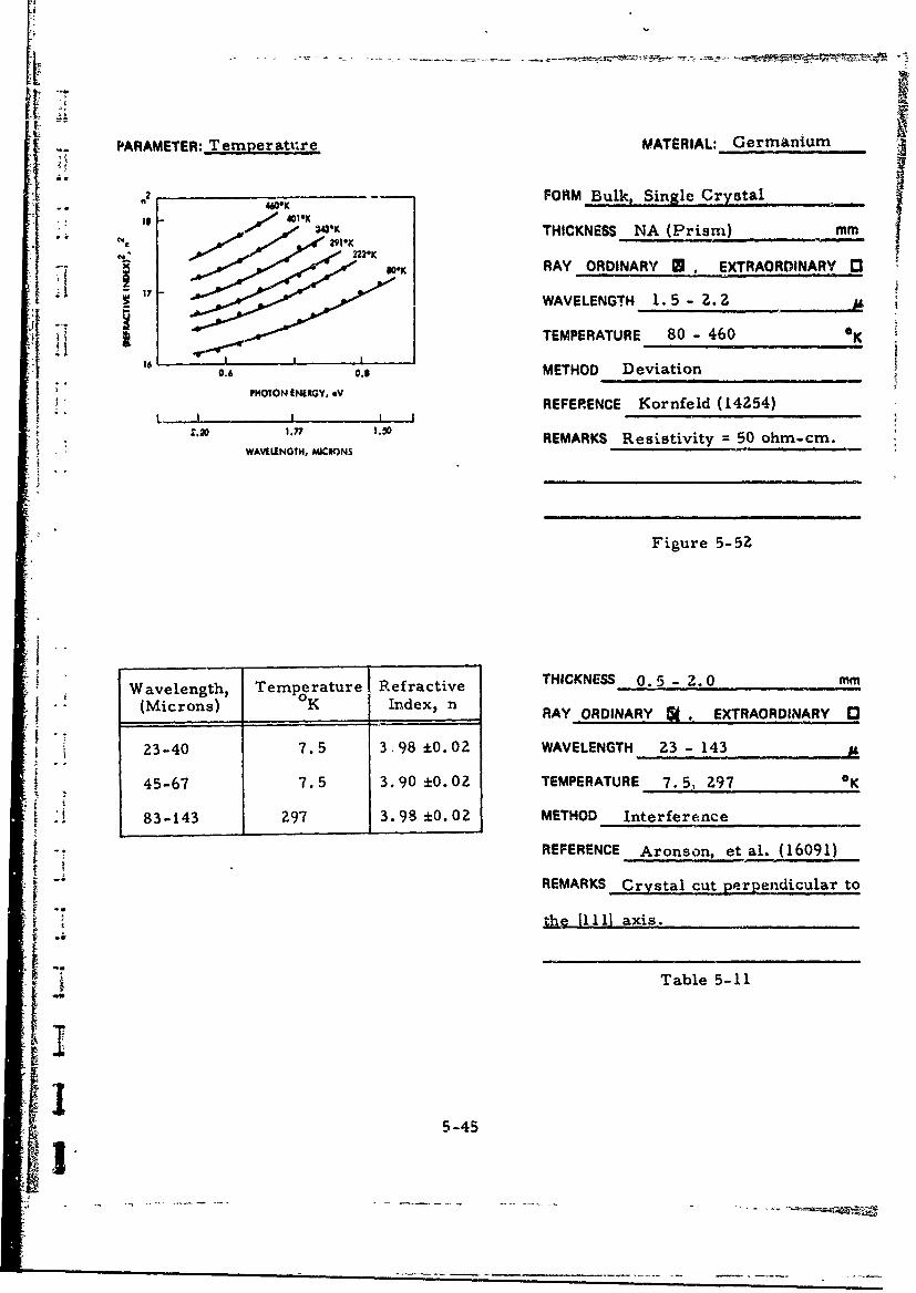
PARAMETER: Temperature MATERIAL: Germanium
2 FORM Bulk, Single Crystal.. n 460*K ., ,,. . ..
-4% THICKNESS NA (Prism) mm
WK RAY ORDINARY B . EXTRAORDINARY [
[ - 17 WAVELENGTH 1.5- 2. Z
TEMPERATURE 80 - 460 K16 •
0.6 0.3 METHOD Deviation7 P HO TO N EN ERG Y , *Vi , i
L IREFERENCE Kornfeld (14254)
"2 1 .7 1.30 REMARKS Resistivity = 50 ohm-cm.i ~ ~~~~WAVELENGTH, MICRONS .. ... . . .
Figure 5-5Z
Wavelength, Temperature Refractive THICKNESS 0. 5 - 2. 0 mm
S(Microns) oK Index, n RAY ORDINARY . EXTRAORDINARY 03
23-40 7.5 3 98 ±0.02 WAVELENGTH Z3 - 143
45-67 7.5 3.90 ±0. 02 TEMPERATURE 7.51 Z97 *K
83-143 297 3.98 ±0.02 METHOD Interference
[ -REFERENCE Aronson, et al. (16091)
REMARKS Crystal cut perpendicular to
~ i tr 11111 axis.
[ Table 5.-1
i5
1 ~ ---- ~-- ------ ----

[S
FPARAMETER:, Temperature NATFRIAL: Germanium
6.0FORM Bulk, Sir;1I-Crvsta1
THICKNESS Not stated mm
5.5 RAY ORDINARY B, EXTRAORDINARY E3
WAVELENGTH 0.6 - 1.7 I,
TEMPERATURE 120, 300 0K
5.0o METHOD Reflection
REFERENCE Potter (27255)
REMARKS4.5
4.0 ,Figure 5-53O.5 i.0 i .3 2.0
PH4OTON twEIoy. eV
II I I
2.4 1.24 0." 0.2
WAWUENGT, MICIONS
Figure 5-54
5.0
4.5
4.0 L0.5 1.0 1.5 2.0
PHOTON ENERGY, *V
L i I
2.48 1.24 0.83 0.42
WAVALENGTH, MAIONS
5-46

PARAMETER: Temperature MATERIAL: Germanium
4.16 FORM Buik
THICKNESS NA (Prism) mm
4.120RAY ORDINARY VEXTRAORDINARY Q
4~ .080 WAVELENGTH 1.8 - 5.3
TEMPERATURE 87 - 297X.
METHOD Deviation _____
4,00 -10*KREFERENCE Cardona (Z569)
VK REMARKS
ILWAVEILNGTH, MIRN0.62 0.41 0.31Figure 5-55
j PFHOTCN EN(RGY, .V
THICKNESS NA (Prism); Film MmT{ j RAY ORDINARY U.EXTRAORDINARY0
4 - ~ *WAVELENGTH 3.0
*TEMPERATURE 90 -400K
Z4 METHOD Deviation, 1Interf$erence
g REFERENCE Gardona, et al. (620)
0 I-J2 00 4 REMARKS_______________________
Figure 5-56
I 5-47

PARAMETER: Temperature-- MATERIAL: Germanium
FORM Not stated
THICKNESS Not stated mm
RAY ORDINARY . EXTRAORDINARY 01
WAVELENGTH 2.35 it
dndT= 5.25 x 10- (K) 1 TEMPERATURE Not stated oK
METHOD Not stated
REFERENCE Rochow (8766)
REMARKS
Table. 5-12
Wavelength, Thermal Coefficient THICKNESS 3.0574 (single crystal) mm(Microns) dn/dT, (oK}-l(Microns) d/TIO-1RAY ORDINARY U , EXTRAORDINARY 0
1.934 5.919 x 10"- WAVELENGTH 2.0 - 2.4 AU
2.174 5.285 TEMPERATURE Z97.5 °K
2.246 5.251 METHOD Interference
2.401 5. 037 REFERENCE Rank, et al. (39713)
REMARKS Measurements in vacuo.
Thermal expansion contributed only
4% to dn/dT.
Table 5-13
5-48
ýF

PARAMETER:, Temperature MATERiAL; Ge%.zeiailmr
Refractive FORM Film
Wavelength, Index, n THICKNESS 0.227 m(Microns) .......K(irn) 77°K 300°K PAY ORDINARY A EXTRAORDINARY C1
8.66 3.77 3.92 WAVELENGTH 8.66 - 12.35 it
9.4 3.81 3.90 TEMPERATURE 77, 300 *K
10.2 3.81 3.93 METHOD Interference
11.22 3.81 3.92 REFERENCE Collins (40273)
12.35 3.82 3.93 REMARKS
Table 5-14
THICKNESS 1.Z x 10"2 mm
RAY ORDINARY * . EXTRAORDINARY D
3.0 WAVELENGTH 2. 0 - 4.0 AL03 'K TEMPERATURE 77 - 395
.Z6* 775 -£956S2.0_8*K METHOD Interference
_- I.. REFERENCE Cardona (2569)187.K
REMARKSJ0U 0 i1L L
2.0 2.4 2.8 3-2 3.6 4.0WAVFLENGTH, MIdCRON S
Figure 5-57
5-49-!

PARAMETER:- Pressure MATERIAL: Germanium
FORM Film mmTHICKNESS -(3- 10) x 10" 3
RAY ORDINARY M . EXTRAORDINARY (3
WAVELENGTH 3.0
(l/n)!dn/dP)T (-0.7 * 0.2) x 10"6 cm2kgI TEMPERATURE 297 0K
METHOD Interference
REFERENCE Cardona, et al. (620)
REMARKS Pressure range
0 - 1.42 x 10⁵ psi
Table 5-15
THICKNESS Not stated mm
RAY OIDINARY U , EXTRAORDINARY 03
WAVELENGTH -3 A
(1/n)Cdn/dP)T (-0.6- 0.15) x 10"6 cmZkg" 1 TEMPERATURE 297 oK
METHOD RF dielectric
REFERENCE Cardona, tt al. (620)
REMARKS Pressure range
0 - 1.42x 10⁵ psi
Table 5-16
5-50
1i

I III
PARAMETER: res.A TR MATERIAL: Germanium __
FORM Film mm
THICKNESS 3.8 x lO 3
RAY ORDINARY *. EXTRAORDINARY •
"WAVELENGTH 2.0 - 4.0 1'
(lI/n)(dn/dP)T (-0.6*0.3)xl0 6 mkg TEMPERATURE Z97 K
METHOD Interference
REFERENCE Cardona (2569)
REMARKS Pressure range
0 - 1 x 10⁵ psi
Table 5-17
.5
•t 5 -5 1
S°

PARAMETER: Film Thickness MATERIAL: Grmanium_
Film Thickness, Refractive FORM Fil-
(Microns) In1dex, n THICKNESS As shown mm
0.07 3.43 RAY ORDINARY 0. EXTRAORDINARY =
0.09 4.12 WAVELENGTH 2.64
0.1 4.07 TEMPERATURE 300 0K
0.18 4.24 METHOD Interference
0. z6 4. Z3 REFERENCE Wales, et al. (31497)
0.375 3.75 REMARKS Unheated substrate with
1. 52 4. 0 electron beam heating.
2.57 3.98
6.5 3.62 Table 5-18
5-52

It"' ~Germanium/
PARAMETER: Film Composition MATERIAL: Zinc _ Sufide_
4.5 FORM Film, mixed (Ge + ZnS)* DEPOSITION PRIESSURIE<10'5 YORK ..
. DEPOSITION S 24,, 10" R THICKNESS (1.9 - 7.3) x 10-5 Ymm 4& FILMS IN HYDROGEN
RAY ORDINARY M EXTRAORDINARY [3
WAVELENGTH Z. -
TEMPERATURE -Z98
METHOD Reflection
REFERENCE Jacobsson (40180)
7 REMARKS Film produced by simul-
2.5taneous evaporation from two sources.
NOTE: The absorption edge is dis-
2.0 placed with a change in con-0 0.2 0.4 0.6 0.8 1.0 centration, facilitating use of
- PARTS Y WEIGHT Of GERMANIJM the film as variable cut-off"filters.
Figure 5-58
5 ,
o
S~5-53

ES
SPARIAMETER:Am, Dep osition r . ..
5s.0 FORM Film--
3
THICKNES (0.5- 5)x 10 Mm
RAY ORDINARY M, EXTRAORDINARY 13-i 4.6 -
SWAVELENGTH 1.0 - 5.0 p
01 In TEMPERATURE- -300 K
.2. ,IA, IM METHOD Transmission
4.0 F REFERENCE Wales, et al. (31497)0 2 4 4
WAVELENOTH, M•ONS REMARKS Preparation on unheated
substrate. Samples labelled TA"T areat a higher deposition rate than "B".Source temperature is a function ofnumber shown. "A" samples are ata higher deposition rate than "B"samples.
Figure 5-59
5-54

PARAMETER: . iIm -Deposition Atmosphete MATERIAL: Germanium
7I
FORM Film fA THICKNESS 10 3 mmI
_. •.RAY ORDINARY M. EXTRAORDINARY =S4.6
-0 WAVELENGTH 1.0 - 5.0
TEMPERATURE 297 K
METHOD Interference, Reflection
L , , REFERENCE Huldt and Staflin (3735).. 2 3 4 5 6 ... =
WAVE NUM11, 1O0 CM"'-t REMARKS Glass substrate.
5.0 3.3 2.5 2.0 1.7 1.4
"WAV•LENGIH, MIkONS Layer thickness: 01.092 p, A LO 0 .
"Figure 5-60
-3THICKNESS (0.5 -5) x l0- mm
4.9 RAY ORDINARY , EXTRADP.DINARY 014.7 - WAVELENGTH 1 - 5.0
& TEMPERATURE -300 'K4. - tw
also METHOD TransmissionS4.3 -
2 152 REFERENCE Wales, et al. (31497)0125
4.1 REMARKS Unheated substrate, electronI I I 1 -6
0 1 2 3 4 S beam heating. oressure = I x10 Torr.WAVELENGTH, MICRONS
Figure 5-61
5-55

PARAMETER: iim e..rmanium,
FORM Film
4.1 THICKNESS (0.5 5) x 10 Mm
4.6- RAY ORDINARY U, EXTRAORDINARY 13
4.4 WAVELENGTH 1.0 - 5.0.
TEMPERATURE -300 0K
I.2 METHOD Transmission
4.0 REFERENCE Wales, et al. (31497)L L I I
0 1 2 3 4 REMARKS Unheated substrate, electronWAVeeNGTH, kMKIONS
beam heating, I x 10.4 Torr oxygen
pressure
Figure 5-62
5-56

U
AAMER Fi'lm Deposnition Atmosvhere MATERIAL:_Germanium •S.. . "'4 yy f --|- - .-- , , ,,.. .
FORM Film -34.6 THICKNESS (0. 5 - 5) A I' ,,M'
4.6 RAY ORDINARY C, EXTRAORDINARY r
..4 -. WAVELENGTH 1.0 - 5.0~~ * 4.4 - ,,-,
1&- 176 TEMPERATURE -300 KS• .2 •& METHOD Transmission
"" .0REFERENCE Wales, et al. (31497)0a M r n 4 5si
REMARKS Unheated substrate, electron- - ~~WAVEUNGT, •CXONS.. .
beam heating, I x 10-4 Torr nitrogen
pressure.S-. Figure 5-63
-- THICKNESS 1-3 mm
RAY ORDINARY • . EXTRAORDINARY E3
WAVELENGTH 1.0 - 5.0 . .
- 4.62 TEMPERATURE 97K
S4.4 0 METHOD Interference, Reflection
REFERENCE Huldt and Staflin (3735)
-~ | t ____ REMARKS Glass substrate. Layer2 3 4 5 6 7
WAVE NUMSNR, I03CM
1
I I I I I I Ithickness: 0 1. 340 p5.0 3.3 2.5 2.0 1.7 1.4
WAVELENGTH, MJCRONS &_ 1. 364 _ __ C3_1.449__.
j Figure 5-64
5-57

PARAMETER: Film Deposition Atmosphere MATERiAL: Gerrmiiluii..
* FORM Film
THICKNESS (0.5 -5) x 10- mm
4.7- RAY ORDINARY .. EXTRAORDINARY 0
4.5 WAVELENGTH 1.0 - 5.0 .
TEMPERATURE "--300 0K
4.3
"ela METHOD Transmission
4.1 1- REFERENCE Wales, et al. (31497)
5 2 REMARKS Unheated substrate, electron
WAVYLINGTH, MKCIONS beam heating, 1 x 10⁻⁴ Torr hydrogen
-pressure.
Figure 5-65
5-58

i55
Film DerositionPARAMETER: Substrate Temperature .AT..RIAL Germarniurm
FORMs9yT COOLDTO 2 FO RM Film4.6 THICKNESS (0,5 - 5) x 10"3
.. • RAY ORDINARY *, EXTRAORODNARY fl-4.2 1 WAVELENGTH I - 5
Sa I36 5
e139 TEMPERATURE 300 'K4.01
0 I 2 3 4 3 6 METHOD Transmission
WAVELENGTH,CRONS REFERENCE Wales, et al. (31497)Figure 5-66
(2730 K) REMARKS Substrate heated from carbon
4. boat. Pre:;sure = 1 x 10- Torr.SIASTRATI TEMD*RATUR 373473K
Figures 5-66 to 5-69
|z4.2 143
4.0.4 , I ! I , I
- 0 2 4 6
WAVELENGTH, MICRON'
". ° 47__ _ _ _ _ _ _ _
Figure 5-67 SA TEMKIIATUhE M473eK
(373 - 473°K) 4.54..5
4.5 4
4.3 -3 a66
''; • •3.9
.. •e ""•*-e1- WAVELE¢NGTH, MICRONS
-A 132I: :.~ . 14
SI I I
0 1 2 3 4 5 6
WAVLENGTH, MICRONS
Figure 5-68 Figure 5-69
(673-K) 13 873-K)
P 5-59

Ii
Film DepositionPARAMETER: Substrate Temperature MATERIAL: Germanium
Film, amorphous andFORM polvcrvstalline
4.083MTTHICKNESS -- I x 10- mm
4.6
SRAY ORDINARY * EXTRAORDINARY 0 13
4.2 - WAVELENGTH 1.25 - 6.5 U
4.0 4"° ' ___,___ TEMPERATURE -,298 K
3."8 METHOD Interference36 I I I I I
1 1.5 2.0 2.5 3.0 3.5 4.0 5.0 6.0 7.0 REFERENCE Gisin and Ivanov (41222 )
WAVEENGTH,, MICRONS REMARKS Evaporation of single crystal
yermanium of resistivity = 40 ohm-cm
from graphite boat onto barium fluoride
substrate at (2-5) x 10"5 Torr pressure.
Figure 5-70
5-60

SI-
PARAMETER: Electric Field MATERIAL:G'r.....
0.02
FORM Single Crystal pn Junction
1o0.01o THICKNESS Not stated mm
RAY ORDINARY M, EXTRAORDINARY 01
00
WAVLEGT 1.6 2
-04TEMPERATURE 300 Kz METHOD Reflection
.0O.02 -- -- 2 A', 125 V/o---2..ý X 10, v/., REFERENCE Seraphin and Bottka (38093)
1.0 X 10⁴ V/cm0.5 x Ios v/AM EAK ,Y.=k• "ae--•REMARKS Wavelength is based on-0.031- l I | I I
-0.12 .0.08 -.. 04 o o0.0 0.0o 0.12
.HOTON ENERGY, b ,E eneryv gap data from McFarlane,I I f I i I _,I
2.26 2.13 1. 1.86 1.75 1." 1.s, et al. (184).WAVEIINGTH, MICRONS AT 300K ONLY
Figure 5-71
I5 61
I --
Ii"
I 5-61
rii " ,'.•a .

[ - - -
ZINC SULFIDE
INTRODUCTION
Zinc sulfide occurs in two crystal forms: cubic (ziticblende or
sphalerite) and hexagonal (wurtzite). This semiconducting material
is used in infrared optics and in luminescent devices. Single crystals
for optical applications have been grown by the static vapor growth
method in which powdered zinc sulfide is kept in the high temperature
region. The powdered zinc sulfide is usually prepared by precipitationfrom aqueous solution. Highly purified zinc sulfide has a resistivity of
approximately 5 x 10⁷ ohm-cm for the hexagonal form, measured in
darkness.
The physical properties of intrinsic zinc sulfide were summarizes
in Table 1-1. A more complete compilation of properties is offered in
Report No. S-11. Figure 1-9 shows the infrared transmission by
zinc sulfide.
DATA
The data for zinc sulfide are listed in Table 5-19 and the wave-
length coverage in Table 5-20. The data cover hexagonal, cubic, amor-
phous, and a mixture of cubic and hexagonal zinc sulfide. No data at
temperatures other than room temperature were located.
Refractive index data for hexagonal zinc sulfide, single crystal
material, are presented in Figures 5-72 to 5-73 and Tables 5-21 to 5-ZZ;
sinc hexagonal zinc sulfide is birefringent, plots for ordinary and
extraordinary rays are included. Cubic crystal data are shown in
Figures 5-71 to 5-77 and Tables 5-23 to 5-25. Figure 5-78 and
Table 5-26 present data for Irtran-2, a polycrystalline material com-
posed of 95 percent cubic and 5 percent hexagonal material Film data
are provided in Figures 5-79 to 5-PAZ and in Table 5-Z7. The dependence1 i PRECEDING PAGE BLANK5-63

of the refractive index on zinc sulfide content has been demonstrated
for a germanium/zinc sulfide film in Figure 5-58.
No significant difference is observed between the bulk data for the
ordinary ray on hexagonal zinc sulfide and for cubic zinc sulfide. Films
tend to have a lower refractive index than bulk material.
Table 5-19. List of Zinc Sulfide Data
-- r rWavelength(Microns) I
Figure Table n or k Form Crystal From To Remarks Parameter
-2 n Bk Sie 0 6 1 . na
5-7 1 n Bulk Single 0 1. 14 Hexagonal Wavelength
-- 73 n Bulk Single 0.6 1.6 Hexagonal Wavelength'-3n Bulk Single 0. 3 I. 6 Hexagonal Wavelength
I-Z2 n eulk Single 4.0 IS.0 Hexagonal Wavelength
5-74 n Bulk Single 0. • 1.4 Cubic Wavelength
S-.3 n Bulk Single 0.7 1.4 Cubic Wavelength
1-75 n Bulk Single 0 3 4.0 Cubic Wavelength
5-2, n Bulk Single 0.7 4.0 rubic Wavelength
.- ZS n Bulk 0.8 2.4 Cubic Wavelength
5.76 n. k Bulk * 20 70 Cubic Wavelength
S-77 n Bulk 0.1 I.S Cubic Wavelength
5- 1t n Bulk Polycryst:" 1.0 1.,0 Wavelength
S-26 n Bulk Polycryst5
1.0 13.0 Waselength
S-79 n Film Amorphous 0.75 2.0 Wavelength
5-80 n Film Amorphous 2.0 14.0 Wavelength
-81 n Film . 0.4 I.Z Wavulength
5-82 n Film 4 0.8 3.2 Wavelength
S-27 n Film * 0.74 1.0 Wavelength
Not stated
95 percent cubic, 5 percent hexagonal (L3TRAN-2. product of E&stman-Kodak Co.)
Table 5-Z0. Range of Refractive Index Data for ZincSulfide (3000 K)
Range i,, Wavelength,Microns
Materi.t From To From To
Bulk, ,uhi 0.3 4.0 to 70
Bulk, hex-gonAl 0.3 1.6 4 Is
Bulk. poly( ryst. 1.0 13
Film, amorphous 0.8 14
5-64

PARAMETER: Wavelength MATERIAL: Zinc Sulfide
FORMBulk. SingleCrvstal. Hexagonal
Z • 2 THICKNESS NA (prism) mm35235ýýiý'ýýEXIRAOROI NARY RAY
ORDINARY ýY RAY ORDINARY E, EXTRAORDINARY US2.25 I I
0 60 0.85 1.10 1.35 1.60 WAVELENGTH 0. 6 - 1.4
WAVE LENGTH, MICRONS
TEMPERATURE "Z 98 K
METHOD Deviation
REFERENCE Bieniewsky &Czyzak(8761)
REMARKS
Figure 5-72
Refractive Index, n
Wavelength, Extraordinary Ordinary(Microns) Ray Ray
0.600 Z.368 Z.3636.625 Z.358 Z.354
0. 6500 2. 350 2. 346 Table 5-21
0.6750 2.343 Z.339
0.7000 2.337 2.332
0.8000 2.328 2.3Z4
0.9000 2.315 2.310
1.0000 2.303 2.301
1.2000 2.294 2.290
[1.4000 2.288 Z.285
5-65

PARAMETER: Wavelength MATERIAL: Zinc Sulfide
Bulk, Single Crystal, .L29 9 FORM Hexagonal
2. e THICKNESS 5 x 10"3 mm
2.7 o RAY ORDINARY U, EXTRAORDINARY U3p2.6
WAVELENGTH 0.3 - 1.6; 4 - 152.5
2.4 TEMPERATURE 293 0 KS,-0o6 0 C-AXIS2.3 -tales 0 60 al CUBIC ciMETHOD Interference
2.2 1 1 . REFERENCE Piper, ef: al. (735)0.5 1.0 1.5 2.0 2.5 3.0 3.5 4.0
PHOTON EI•if*Y. eV REMARKS-• I I I I I I I I
1.5 1.0 0.0 0.6 0.5 0.4 0.35
WAVIEUENGTH, MICRONS
Figure 5-73
Wavelength, Refractive Index,(Microns) n Table 5-22
4- 15 2.26k 0.06
5-66

PARAMETER: v-length MATEbi: Zinc S
Bulk, Single Crystal," ' FORM Cubic tun
"2.40 THICKNESS NA (prism)
xC RAY ORDINARY m EXTRAORDINARY r3
S.WAVELENGTH 0.7 - 1.4~2.30
TEMPERATURE ,-298 OK
-_ _ _METHOD Deviation2.20 I I It
o.8 1.0 1.2 1.4
WAVE LENGTH. MICRONS REFERENCE Czyzak, et al. (6331)
REMARKS
Figure 5-74
- Refractive Index, nWavelength,
(Microns) Cal culate Observed
0.700 2.332 2.334
0. 900 2, 303 2. 306 Table 5-23
1. 050 2. 293 2. 2931.200 2.285 2.282
1.400 2.280 2.284
"5-67

PARAMETER: Wavelength MATERIA.:_Zinc Sulfide
Bulk, Single Crystal,FORM Cubic mm
2.7 THICKNESS NA (Prism)
2.6 RAY ORDINARY , EXTRAORDINARY
i 2.5 •WAVELENGTH 0. 3 - 4.0 A2.4- TEMPERATURE -298 0 K
2.3I METHOD Deviation2.2
0.3 0.3 1.3 1.3 2.3 2.1 33 3. REFERENCE Czyzak, et al. (i49!4)
WAVIUNGr,. M•CRONS REMARKS
Figure 5-75
Refractive Index, n THICKNESS NA (Prism) mmWavelength,
(Microns) Calculated Measured RAY ORDINARY U * EXTRAORDINARY 0
WAVELENGTH 0.7 - 4.00.700 Z..32-9 2. 332 TEMPERATURE -2Z98 oK1.000 2.Z92 Z.-93
METHOD Deviation1.500 2.270 2..Z75
2.000 2.260 2.263 REFERENCE Czyzak, et al. (14914)
2.500 2.256 2.256 REMARKS
3.000 2.253 2.253
3.500 2.251 2.251
4.000 2.250 2.251 1 Table 5-24
5-68

PARAMETER: Wavelength MATERIAL: Zinc Sulfide
Wavelength, Refractive Index, FORM Bulk, Cubic mm(Microns) n THICKNESS NA (Prism)
-0.8 2.3146 RAY ORDINARY U , EXTRAORDINARY 03
S0.9 2.3026 WAVELENGTH 0.8 - 2.4
TEMPERATURE '-298 K1.0 Z.2932
METHOD Deviation-• -1.2 2.28221222REFERENCE Bond (19989)
I. 4 2. 2762 REMARKS Natural crystal from Spain
1.6 2.2716
1.8 2.2680
Table 5-25S2.0 2. 2653
1 4,2.2 2.2637
~ 12.4 2.2604
5I
itp
"S-
-. 5-69

PARAMETER: Wavelength MATERIAL:_ Zinc Sulfide
FORM Bulk, Cubic
z THICKNESS Not Stated mm
V s RAY ORDINARY A *,EXTRAORDINARY 0Z 4 .
S2 - WAVELENGTH 20 - 70-- J. II I I I
C TEMPERATURE 300 K
6 ZnSOJIC METHOD Reflection
SREFERENCE Manabe (Z8526)
0 " REMARKS Natural crystalM0 30 40 so 60 70
WAVLENGTH, MICRONS
Figure 5-76
THICKNESS NA (Prism) mm
2.5 RAY ORDINARY U, EXTRAORDINARY E3
x WAVELENGTH 0.7 - 1.5
2.3 __ TEMPERATURE -Z98 OK
SMETHOD Deviation
0.7 0.9 1.1 1.3 !.5WAVELENGTH, MICRONS REFERENCE DeVore (40Z76)
REMARKS Sphalerite, natural crystal
Figure 5-77
5-70
I

PARAMETER: Wavelength MATERIAL:".*n" . .. ,,""
FORM Bulk, Polycrystalline
THICKNESS Not Stated mm2.2 -- TRAN 2 RAY ORDINARY 1 EXTRAORDINARY 192. -2.0 WAVELENGTH 1.0 - 14.0
Z 1.8 •J.-
2 4 6 8 10 12 14TEP AURi "TEMPERATURE ~ 298 oWAVUENGITH, MICRONS
METHOD Not Stated
REFERENCE Kodak [1967]
REMARKS IRTRAN-2 material
•b
Figure 5-78
Wavelength. J Refractive Index Wavelength, Refractive Index.S(Microns) n (Microns) n
1.0000 2. 291J7 6.0000 2.2381
1.2500 Z. 2777 6.2500 2. 2363
1.5000 z. 2706 6.5000 2. 2344
1.7500 2.2662 6.7500 2. Z324
S1 2.0000 2. Z631 7.0000 2. Z304
12.20 ZaO . 608 7. 20 SO2.22822.5000 2.2589 7. 5000 2. 2260IZ. 7500 2.2573 7."500 2.2237
3.0000 2.2558 8.0000 2. 2213 Table 5-26i 3.2500 2.2544 8.2500 Z.2! 88
3.5000 Z.2Z531 8.5000 2. 21 62
- 3.7500 2.2518 8.7500 2.2135
4.0000 2.2504 9.0000 2.2107
4.2500 2.2491 9.2500 2. £078
4.5000 2.2477 9.5000 2.20484. 7500 2. 2462 9. 7500 2. 2018
1 5.0000 2.2447 10.0000 2.1986
5.2500 2.2432 11.0000 2.1846
5.5000 2.2416 IZ.O000 2.1688
5.75002. 2399 13. 0000 2.1508
5-71I-'

PARAMETER: Wavelength MATERIAL: Zinc Sulfide
FORM Film, Amorphous
-3THICKNESS (1-4) x 10 mm
S2.40 RAY ORDINARY 19 EXTRAORDINARY "1
S2.35 I,._ WAVELENGTH 0.75 - 14
TEMPERATURE -298 OK
2.7 '1. . 1.50 _ 75 2.. METHOD Transmission, Reflection0.7.% 1.00 1.25 1.50 I 75 .•
WAWVE114. MICRONS REFERENCE Hall & Ferguson (2609)
REMARKS Vapor-deposited film-
0. 75 - 2 micron data on glass sub-
strate 2 - 14 microns on rocksalt substrate
Figure 5-79
C
2.3
2.22. Figure 5-802.0
S 2.0 I I I I I I I
2 3 4 5 6 7 $ 1 10 1I 12 13 14
WAVLENGTIH. MICRONS
5-72
. I.
I,

PARAMETER: Wavelength MATERIAL: Zinc Sulfide
_FORM Film2
.60
2 55 THICKNESS Not stated mm
s *.. c RAY ORDINARY B EXTRAORDINARY 3
I-/ WAVELENGTH 0..4 - 1.22. 40
U -2984 23- TEMPERATURE K298
METHOD Interference
"2 25.I REFERENCE Burgiel, et al. (34617)
2.20tO 1.5 2 0 2.5 3.0
PHOTON ENERGY., V REMARKS Sputtered and evaporated
films used with identical results.1,24 0.62 0.41
WAVELENGTH., MICRONS Sputtered film w ts predominantly
cubic.
Figure 5-81
-3- "" THICKNESS 2.5 x 10 mm
zx .0 0 °d ' A ( - 0-" _ RAY ORDINARY :. EXTRAORDINARY 0z 0 _a a 'AI (1 1 • , 0-5 IOR)
U 2.3- WAVELENGTH 0.8 - 3.2
V I I3 TEMPERATURE -298 oK3- 5 7 9 11 10cMI
WAVE NU MIBRMETHOD InterferenceS "• I t ! I I I | I I
3,3 2 0 1.4 1.1 091REFERENCE Huldt & Staflin (3735)
WAVELE'NGTH, MICRON$
REMARKS Evaporation onto glass
substrate in atmosphere of air orAir plots: 0, layer with d 2. 500k,, A,d = Z, ZZ1V; 0, d = 2. 258k. Nitrogen nitrogen.
plots: 0, laytr with d = Z. 5014, A,d = Z. 2334L. + determined by calculation. Figure 5-82x determined from Brewster angle; remainingplots from geometrical thickness of film.
5-73F'

PARAMETER: Wavelength MATERIAL: Zinc Sulfide
FORM Film
Refractive Extinction - 4
Wavelength, Index, Coefficient,
(Microns) n k RAY ORDINARY U. EXTRAORDINARY E
0.740 2.30 0.000 WAVELENGTH 0.74 - 1.0
TEMPERATURE -298 0K0.900 2.23 0.000
METHOD Trarsmission, Reflection0.980 2.27 0.000
_ __ _ _ _REFERENCE Kuwabara & Isiguro (40442)
REMARKS Film evaporated onto glass-4
substrate at- 10 Torr,
Table 5-27
5-74

[I
CADMIUM TELLURIDE
INThkODUCTION
Cadmium telluride is a semiconductor that has found application
in infrared optics and semiconductor devices including solar cells.
This material may show both n- and p type conduction; addition of
excess cadmium gives n-type conduction and conversely, addition of
excess tellurium gives p-type conduction.
Cadmium telluride is usually preparcd from electrolytic cad-
mium and vacuum-distilled tellurium by direct combination at anelevated temperature under a nitrogen atmosphere. Zone refining is
-* used for further purification. The electrical and optical properties
are strongly affected by deviation from the stochiometric ratio of the
components (cadmium and tellurium). Details concerning the equilib-
rium phase diagram for cadmium telluride may be located in EPIC
Data Sheet DS-157. The electrical resistivity of highly pure single
crystal cadmium telluride at room temperature is approximately
107 ohm-cm. The optical tra:ismission by cadmium telluride is
shown in Figures 1-9 and 1-10.The physical properties of cadmium telluride were summarized
in Table 1-1.
EPIC Report S-11 provides additional property data on cadmium
telluride. As with other semiconductors, different doping levels inauthors' reports make it often difficult to compare their results.
"DATA
All data presentations for cadmium telluride are listed in
"Table 5-Z8 and a 3ummary of wavelength and temperature coverage is
plotted in Figure 5-83. Figures 5-84 to Figure 5-88 and Tables 5-29
to 5-31 represent refractive index spectra for bulk single crystal
material. Below five microns, the pure or lightly n-doped materials
show no wide differences in refractive index. At longer wavelengths
the data exhibit a far wider spread between the author's data and it
"5-75

would he difficult to recommend a "best" set of values. Heavily
n-doped mat.-,ials are represented by data in Figures 5-89, 5-90and 5-91. 'rh, data in Tables 5-32 to 5-34 and Figure 5-90 and 5-9s,
could not be identified regarding their crystalline status (e. g., single
crystal) but, except for heavily doped materials, they show no marked
departure from the spread for single crystals.
Figures 5-92 to 5-95 and Tables 5-35 to 5-37 cover polycrystal-
line materials and the data are similar to those obtained from single
crystal material of a similar doping level.
The temperature dependence of the refractive index is the sub-
ject of Tables 5-38 to 5-39 and Figures 5-96 to 5-101. The relative
sparsity of such data does not permit any generalization.
two
Z 100
0
2
10
I , , ! i I I I i I I0 100 200 300 400 500
TEMPERATUR, 'K
Figure 5-83. Wavelength and Temperature Rangefor Cadmium Telluride Data
5-76

-Zý
Table 5-M.8. List of Cadmium Telluride Data
Wavelength._Micron_)
Figure Table n or k Form Crystal From To Remarks Parameter
5-84 n 1 Bulk Single 0.085 2.6 Wavelength
5-29 n Bulk Single 2.0 10.0 Wavelength
5.85 n Bulk Single 12.5 300 8, 300"K Wavelength
5-86 n Bulk Single 133 1000 4. VK Wavelength
5-87 n, k Bulk Single 37 85 100, 300"K Wavelength
5-18 n Bulk Single 5.0 10.0 Wavelength
5-30 it Mulk Singie 0.87 1.00 n-type 493". 373"K Wavelength
5-89 n Bulk Single 6. 5 14.5 n-type, heavily doped Wavelength
5-31 n Bulk Single 0.90 1.1 n-type Wavelength
5-32 I Bulk * 2.5 2.5 n-type Wavelength
5-33 n Bulk * 8.0 14.0 n-type Wavelength
5-34 n Bulk * 10.0 10.0 n-typt Wavelength
5-90 n. k Bulk * z0 200 n-type, heavily doped 100"K Wavelength
5-91 n. k Bulk 20 200 n-type, heavily doped 300*K Wavelength
5-92 n Bulk Polycryst. 1.0 16.0 Wavelength
5-35 n Bulk Polycryst. 1.0 16.0 Wavelength
5.93 n. k Itulk Polycryst. 50 75 90"K Wavelength
S-94 n. k Bulk Polycryut 55 78 300"K Wavelength
5-95 n Bulk Polycryst. 220 1000 W.Avelength
.-36 n1 Bulk Polycryst. 1.0 10.0 Wavelength
5-37 u Bulk Polycrysut. 23 Z8 n-type Wavelength
5-38 n Bulk Single 0.87 1.00 n-type, Z93. 373'K Temperature
5-96 n Bulk Single 37 85 100. 300-K Temperature
5-9? nI Bulk * 20 200 n-type. 100*K Temperature
5-98 n Bulk * 20 200 n-type. 300'K Temperature
5-99 11 Bulk * 12.5 300 8,. 300"K Temper; .ure
5-100 n Bulk Polycryst. 50 75 90"K Temperature
5-101 n Bulk Polycryst. 55 78 300*K Temperature
"5-39 1/n A) Bulk Single 10.6 10.6 Z93 - 318'K TemperaturedT
"L Not Stated
5-77*
Au . . .. . . .

Cadmium
PARAMETER: Wavelength MATERIAL: Telluride
FORM Bulk, Single Crystal
2.95 - THICKNESS NA (Prism) mm
II RAY ORDINARY A1 EXTRAORDINARY "x
Z WAVELENGTH 0.085 - 2.6
~280-U 0z TEMPERATURE -298S2 75
2 70 METHOD Deviation
0.4 0 5 0.6 0.7 0.8 0.9 1.0 1.1 1,2 1.3 1.4 1.5 REFERENCE M arple (15085)PHOTON ENERGY, .V
,I , i. I . I I . I .I I I , i REMARKS Material grown from2.6 2.2 1.8 1.6 1.40 1.20 1.10 1.0 0.90.85
WAVELNGTH, Mr8ONS melt containing < 10 ppm total
impurities.
Figure 5-84
Wavelength, Refractive THICKNESS NA (Prism) mm(Microns) Index, n(Microns) idxnRAY ORDINARY U , EXTRAORDINARY 03
2. 0 2. 710 WAVELENGTH 2 - 10
3.0 Z.694 TEMPERATURE -298 OK
4.0 2.687 METHOD Deviation
5.0 2.680 REFERENCE Vitrikhovskiy (31017)
6.o0 . 675 REMARKS
8.0 2.669
10.0 2.658
Table 5-29
5-78

Cadmium.AAh-- C..AI 'Tolh,1.1,'
PARAMETER: Wavelength ........ ,
4.5 FORM Bulk
THICKNESS 0. 172 mm40 ,
'40 8' X DATADOUE TO DWAR RAY ORDINARY I EXTRAORDINARY 0WINDOW CUTOFF,CALCULATED 8* V CURVE • 1-
3 5 NEARLYCOINCIDENT WAVELENGTH 12. 5 - 300WITH 300* K CURVE W E ,,
/ - AT 300' K fCALCULATED)
--- AT 8* V ICALCULATED) TEMPERATURE 8, 300 oKS3.0 0 AT 300* K (MEASUAED)\ T o AT8"K (MEASURED METHOD Interference
2s REFERENCE Johnson, et al. (40781)
0 10 20 40 70 100 20 400 REMARKS Resistivity = 8.5x10 5 ohm-cm.WAVELENGTH, MICRONS
Figure 5-85
THICKNESS 1.22 mm
. RAY ORDINARY 1 EXTRAORDINARY 03"•3.3 0 ..... .__ _ __ __ _ __ __ _ __ ___--__ _0O
- WAVELENGTH 133 - 100 AL
_3.2 ,TEMPERATURE 4.2 oK
00o 0 .. METHOD Interference40 0
"3.1 REFERENCE. Halsted, et al. (26678)
REMARKS3.0 06 8
0 0 20 30 40 50 60 70 so
WAVE NUMSER, CM"1
L I ; _1000 333 200 143 Figure 5-86.
WAVELENGTH, MICRONS
5-79

LICadmium
PARAMETER: Wavelenuth MATERIAL: Telluridu
FORM Bulk, Single Crysal
.0.K A~ THICKNESS Not stated mmV 6z RAY ORDINARY A EXTRAORDINARY 1"
_ WAVELENGTH 37"85 ,.
8 TEMPERATURE 100, 300 K
4 METHOD Reflection
-"I'.'.-- REFERENCE Manabe, et al. (28526)
"30 W0 so M0ft 0NsoR EM A R KS
Figure 5-87
THICKNESS Not stated mm
RAY ORDINARY A EXTRAORDINARY 03
"WAVELENGTH 5 - 10•- 2.9
27 TEMPERATURE 300 OK
w METHOD Reflections 6 7 8 9 10
WAVELENGTH, MICRONS REFERENCE De Nobel (306)
REMARKS
Figure 5-88
5-80

CadrfiumPARAMETER: Wavlgn MATERIAL: Teiluridae
Temperature, Wavelength, Refractive FORM Bulk, Single Crystal°K (Microns) Index, n_.... ... _THICKNESS, 0,.1 mm
Z93 0. 865 3. 50 max. RAY ORDINARY U , EXTRAORDINARY Cl
293 0.900 3.20 WAVELENGTH 0.87 - 1.00
293 1.000 2.80 TEMPERATURE -298 0K
373 0.87Z 3.40 max. METHOD Reflection, Transmission
S373 0.9C0 3.15 REFERENCE Konak (11590)
373 1.000 3. 20 REMARKS n-type material, resistivity
1' -105 ohm-cm
Table 5-30III THICKNESS 0. 63, 1.10 mIm
RAY ORDINARY 1 , EXTRAORDINARY 03. WAVELENGTH 6.5 - 14.5 A"
2.8 TEMPERATURE -298 OK2. 7 S , 10 11 2 13 14 I5 METHOD Reflection2.6 7 9 to 1 12 1 14 5
WAVNL.NGTH, MICONS REFERENCE Planker & Kauer (40526)
REMARKS -n-tye material, Gallium
F' concentration -5x10 1 7 cm-3S] , Figure 5-89
5-81-41
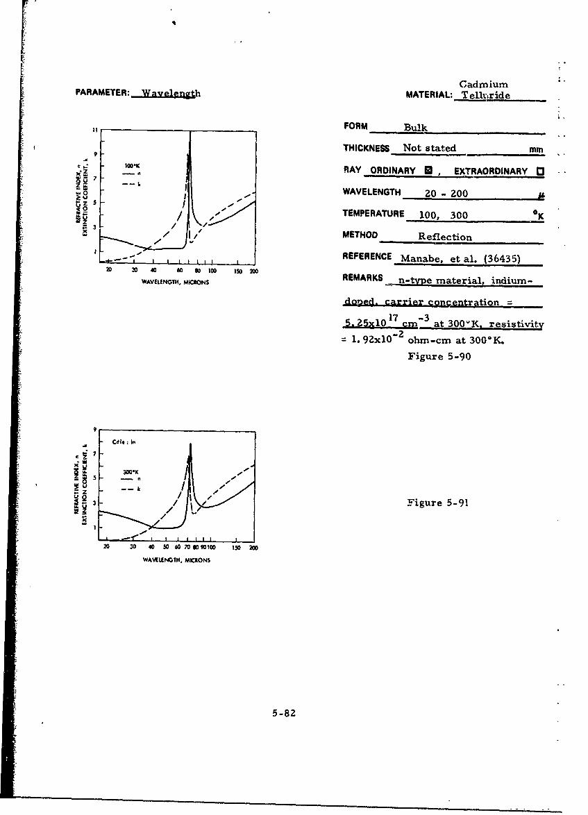
CadmiumPARAMETER: jvlgh MATERIAL: Tel1,ride
FORM Bulk
THICKNESS Not stated mmS100'K RAY ORDINARY U , EXTRAORDINARY C -
0 WAVELENGTH 20- ZOO
2= 3/ /TEMPERATURE 100, 300 0 K/ / METHOD Reflection
- REFERENCE Manabe, et al. (36435)
WAVELENGTH. MICRONS REMARKS n-tvie material, indium-
dopned. carrier concentration
5.j25x10 17 -3 at 300vK. resistivity
1. 9ZxlO"2 ohm-cm at 300*K.
Figure 5-90
9
Cdf*: In
* ,20K I - "--- K
2/ Figure 5-91
3-x
20 30 40 50 60 70 1009 0 1 O 200
WAVELENGTH, MICRONS
5-82

V Cadmium&AAWCQ1A1_PARAMETER: _ _ _ _ e___ T__ '___ T__ _ ,
Wavelength, Refractive Index, FORM Bulk, single crystal(Microns) n
_ THICKNESS 1.0 min
0.903 3.47 0.05 RAY ORDINARY A , EXTRAORDINARY 03
1. 100 3. 13 . 0. 04 WAVELENGTH 0. 90, 1. 10 ,t
TEMPERATURE -298 0K
METHOD Not stated
REFERENCE Garlick, et al. (7771)
REMARKS n-type, indium-doped,
concentration not stated.
Table 5-31
Wavelength, Refractive Index, THICKNESS 4. 0 mmMicrons n1 McnnRAY ORDINARY . EXTRAORDINARY 012.5 2.70
WAVELENGTH 2. 5 _t
TEMPERATURE -298 OK
METHOD Reflectance
REFERENCE Marple (10559)
REMARKS Pure n-,pie material
with carrier concentration
- 6x10 1 4 cm-3
Table 5-32
5-83

Cadmium
PARAMETER: Wavelength MATERIAL: Telluride___
Wavelength, Refractive FORM Bulk
, THICKNESS Not stated mm
8-14 2.67 RAY ORDINARY U EXTRAORDINARY 0
WAVELENGTH 8 - 14
TEMPERATURE- 298 0 K
METHOD Interference
REFERENCE Fisher & Fan (5400)
REMARKS n-type material with elec-
tron concentration ~ lx10 1 5 cm-3
Table 5-33
THICKNESS Not stated mm
Wavelength, Refractive(Microns) Index, n RAY ORDINARY 0I, EXTRAORDINARY 03
WAVELENGTH 10 p10 2.61
TEMPERATURE -298 OK
METHOD Interference
REFERENCE Davis & Shilliday (3648)
REMARKS Pure n-type material
with carrier concentration15 -3
-lxl0 cm
Table 5-34
5-84

K -
Cadmium
PARAMETER. Wavelength MATERIAL: _ _eiuride
"FORM Bulk, polycrystalline
"THICX(NESS Not stated mm
" 0 RAY ORDINARY O EXTRAOnDINARY 01•z2 8 TN6
. 2.6 WAVELENGTH 6. -. 62.4 L
I 2 4 6 to 12 14 It TEMPERATURE 298 OK
WAVELEWGTH. MCRONS
METHOD Not stated
"REFERENCE Kodak (1967)
REMARKS
Figure 5-92
[Wavelength. Refractive f Wavelength, Refractive
(Microns) Index. n (Microns) Index. n
1.0000 2.838 6.2500 2.681
1.2500 2.773 6. 5000 2.680
1.5000 2. 74Z 6.7500 2.680
"1.7500 2.725 7.0000 2.679
2.0000 2. t14 7. 2500 2. 678
2. Z500 2. 707 7. 5000 2, 678
1 2.5000 2.702 7.7500 2.677 Table 5-35
1 Z. 7500 Z. 698 8.0000 2.677
"3.0000 2.695 8.2500 Z. 676
3.250C Z. 693 8.5000 2.675
3. 50CO 2.691 8.7500 2.675
"3.7500 2.689 9.0000 2.674
I 4.0000 2. 688 9.2500 2. 674
"i 4. 2500 2.687 9.5000 2.673
4.5000 2. 68W 9.7500 2.672
4.7500 2.685 10.0000 2. 672
5.0000 2. 684 11.0000 2.669
5.2500 2.683 12. 0000 2.666
5. 5CO^ 2. 683 13.0000 -. 663
5.7500 2. 682 14.0000 z.660
6.0000 2.681 15.0000 2.657
16.0000 j2.655
"5-85

I
PARAMETER:J Wywength MATERIAL: Telluride
FORM Bulk, Polycrystafline mm13 -I13
THICKNESS Not stated
S1-RAY ORDINARY U EXTRAORDINARY "
10 , WAVELENGTH 50 - 78
9- TEMPERATURE 90, 300 OK
- METHOD Reflection
REFERENCE Mitsuishi (481)z REMARKS2 6 __ _ _ _ _ _ _ _ _ _ _
3 Figure 5-93
so 700s
WAVILENGTH, MKCONS
I I I I I
0.025 0.021 0.01 0.016
PROTON EINI3Y, eV
5-86

-Cadmium •
PARAMETER: WvlenWgt.h (Cont' d from preceding page) MATE•A.: T
I . 13
to.
9.
1 •Figure 5-94
5.
4"
3
Ak
3,
50 3 70 w
WA V IING I MIRONS
0 025 0 021 0 018 0_06
PHiOTON~ ENERG~Y, -V
5r-- J.
i~l 5-87
._

Cadmium?ARAMETER: Wavelength MATERIAL: Telluride
FORM Bulk. polycrystalline
THICKNESS - 3 mm
Wavelength, Refractive RAY ORDINARY 0 . EXTRAORDINARY D(Microns) Index, n WAVELENGTH 23.3 - 28
23.35 2.58TEMPERATURE -29P 0K
27. 95 2.53METHOD Interference
REFERENCE Lorimor & Spitzer (20784)
REMARKS Pure, n-type with carrier
15 -3concentration - 1IO15 crm"3
at 298*K
Table 5-37
5-88

CadmiumPARAMETER: Wavelength MATERIAL: Telluride
FORM Bulk. Polycrystalline
3 28 THICKNESS Not stated mm
RAY ORDINARY . EXTRAORDINARY D3
3.24 WAVELENGTH 2z0 - 1000 AL- TEMPERATURE -298 0K
3.20 W____4--_OSMETHOD Interference200 400 600 100 1000
w, VE,,DTH, MrRONS REFERENCE , Randall & a,,rcliffe(33290)
REMARKS IRTRAN-6 material
Figure 5-95
Wavelength, Refractive index, THICKNESS NA (Prism)j mmRAY ORDINARY M , EXTRAORDINARY 3
1.0 2.839 WAVELENGTH 1.0 - 10 A.
1.5 2.7422.0 Z.713 TEMPERATURE 298 K
2.5 2.702 METHOD Deviation3.0 2. 695 REFERENCE 1radd (27063)3.5 2.691
4. 0 2. 688 REMARKS ITRAN-6 material
5.0 2.6846.0 2.681
7.0 2.679
8.0 2.677 Table 5-36
9.0 2.674
10.0 2.672
5-89

r
CadmiumPARAMETER: Temperature MATERIAL: Telluride
Temperature, Wavelength, Refractive FORM Bulk. Single Crystal°K (Microns) Index, n THICKNESS 0. 1 mm
293 0. 865 3. 50 max. RAY ORDINARY M , EXTRAORDINARY 03
293 0.900 3.20 WAVELENGTH 0.87 - 1.00 0
Z93 1.000 2.80 TEMPERATURE -298 0K
373 0. 872 3. 40 may. METHOD Reflection, Transmission
373 0.900 3.15 REFERENCE Konak (11590)
373 1. 000 3.20 REMARKS ".1-type material,
resistivity = 105 ohm-cm
Table 5-38
THICKNESS Not stated mm
300oK . RAY ORDINARY • ' EXTRAORDINARY 0
- --- I- 1
0' 7' WAVELENGTH 37 85
_ 4 -
_ 2 -'_ , TEMPERATURE 100, 300 OKIO II I
10 - CdT*
SCMETHOD ReflectionS I t6 -
z6 ¾. REFERENCE NManabe. et al (28526)
2 REMARKS
30 40 50 60 70 80
WAVELENGDH. MICRON3
Figure 5-96
5-90

r -i
CadrnuimPARAMETER: Temperature MATERIAL: -Telluride
FORM Bulk
11 THICKNESS Not stated mm
9 RAY ORDINARY • , EXTRAORDINARY 0€ : " I00 *K
z n WAVELENGTH 20 - ZOO1z - 7--- I,0- TEMPERATURE 100K 300 K
-0 - 100 •ju •t., 0 ,•av
I-/I METHODau- z ,/ /
3J
3 REFERENCE Manabe, et al. (36435)
I IiiREMARKS n-tYve material, indium-...2 3 40 60 80 100 150 2D0
WAVELENGTH, MICIONS doped, carrier concentration.17 -3
5.25xl01 7 cm at 300'K, resistivity
1.92xlO"z ohm-cm at 300*K.
Figure 5-97
9
CdTe. in
I nog. 300lK -
Z= zFigure 5-983C -
20 30 40 50 60 70 8090100 150 200
WAVELENGTH, MICtCtN5
II[••9

CadmiumPARAMETER: Temperature MATERIAL: Telluride
FORM Bulk4.5
THICKNESS 0. 172 mm
4.0 N RAY ORDINARY • EXTRAORDINARY 3- DUE TO DEWAR
z CCUt.ATEI 8" K CUTVF WAVELENGTH 12. 5 - 300- 3 5 NEARLY COINCIDENT SWITH 300* K CURVE
P -AT 300' K 'CALCULATED% TEMPERATURE 8. 300 K---- AT 8* ý fCALCULATED)
3.0 At 300* K 'MEASURED) METHOD Interferenceo AT 8* K (MEASURED)
042 REFERENCE Johnson, et al. (40781)
4(. ; . REMARKS Resistivity = 8. 5xlO5 ohm-cm0 10 20 40 70 100 200 400
WAV:LENGTH, MICRONS
Figure 5-99
5-92

iiCadmium 'PARAMETER: Temperature MATERIAL: Telluride
13 FORM Bulk, Polycrystalline90'K
12 THICKNESS Not stated mm
II RAY ORDINARY C, EXTRAORDINARY 0
10 k WAVELENGTH 50 - 78
TEMPERATURE 90, 300 0K
8. METHOD Reflection
7 REFERENCE Mitsuishi (481)
v 6 REMARKS
4
3 -Figure 5-100
2
05s 60 70 8D
WAVELENGTH, MICRONS
I I I I I I
0.025 0.021 0.018 0.016
PHC'ON ENERGY, .V
5-93

CadmiumPARAMETER:- Temperature (Cant'd from preceding page) MATERIAL: Telluride
1 300*K
9l1-,'-
I 1
f 7 Figure 5-101
S~f\
-i
0 I i
50 60 70 80
WAVY LENGTH, MICRONS
L I- I I I I
0 025 0.021 0 018 0 016
PHOION ENERGY. eV
5-94
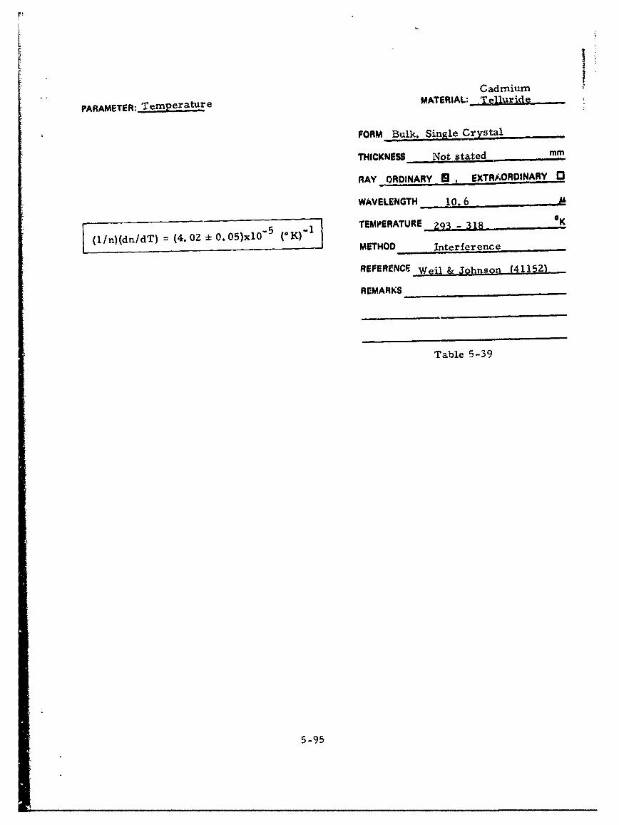
[ i ¸
Cadmium
PARAMETER: Temperature MATERIAL: Tefluride
FORM Bulk, Single Crystal,
THICKNESS , Not stated mm
RAY ORDINARY 9 , EXTRA.ORDINARY 13
WAVELENGTH 10.6
5 1TEMPERATURE 293 - 318 OK
E(l/n)(dn/dT) = (4. 02 ± 0.05)xlO5 (*K)" I
METHOD- Interference
REFERENCE Weil & johnson (411521)
REMARKS
Table 5-39
5-95

ZINC SELENIDE
INTRODUCTION
Zinc selenide is a eemiconductor that has found application in
infrared optics and in cathodoluminescence. Zinc selenide is a rela-
tively new material and no generally recommended preparation method
appears to have evolved thus far. Preparation methods include the
direct preparation from the elements (Zn + Se) under argon and the
reduction of a solution of zinc selenite hydrazine with subsequent
decomposition of the precipitated hydrazine complex by addition of
acetic acid. Typical crystal growth methods use zinc selenide powder
as starting material for the growth of single crystals,
Zinc selenide transmits infrared light to a wavelength of eighteen
microns as shown in Figure 1-9. Evaporated films of zinc selenide
have a resistivity of 108 to 109 ohm-cm at 3000 K. Tne physical prop-
erties of zinc selenide were summarized in Table 1-1 and are given in
greater detail in EPIC Report S-11.
DATA
All data presentations for zinc selenide are listed in Table 5-40
and a summary of wavelength and temperature coverage is plotted in
Figure 5-102. Refractive index data as a function of wavelength are
shown in Figures 5-103 to 5-111 and Tables 5-41 to 5-42. The data
agree quite well with one another from one to twenty microns, but at
lcnger wavelengths the data are rather scattered. The only single
crystal result agrees fairly weli with polycrystalline data over the
range from 1. 0 to . 8 microns. The zinc selenide compilations also
include a number of plots of extinction coefficient measurements. The
temperature dependence of the refractive index and the extinction
coefficient is the subject o), Figures 5-112 to 5-I16.
PME ING PAGE BLANK
L -97

Table 5-40. List of Zinc Selenide Data
- I .-_ .........
I ~Wavelength.,(Micron)
Figure I able n or l Form Crystal From To Remark3 Parameter
5-103 n. k Bulk Single 20 35 Wavelength
5-104 n Bulk I Polycryst 0.8 2.5 " Wavelength
5-105 n Bulk Polycryst 2. 0 13 198°K Wavelengtn
5-106 n Bull. Polvcryst 2.0 14 Z95 K I Wavelengtr
5-107 5--4I n Bulk Polycryst 1.0 23 i Waveiength
5-108 nk Bulk Polycryst 10 120 90"K Wavelength
5-109 n. k Bulk Polycryst 10 125 500"K Wavelength
5-110 n. k Bulk Polycryst 28 6- 77. 290 K Wavelength
5-111 n. k Bulk Polycryst 28 6 7, 290' K W wavelength5-42 n Film t 0.8 1.9 Wavelengtih
5-112 n. k Bulk Single 20 85 Temperature
5-113 n Bulk Polycryst 2.0 13 lq8 K Temperature
5-114 n Bulk Polycryst 2.0 14 235BK j remperature
5-115 n. k Bulk Polycryst 10 1211 90"K Temperature
5-116 n. k Bu)k Polycryst I0 125 500lK I emperature
5-117 n, k Bulk Polycryst 28 67, 7-,.290"K ' lerperature5-118 n. h Bulk Polycryst 28 67 77. 290"K Temperature
*Not stated
1000 -- __
100
z
10
0 M00 ?00 300 400 50o
TEI •tRATIJt•, *K
Fignire 5-10Z. Wavelength and TemperatureRange for Zinc Selenide Data
5-98

PARAMETER: Wavelength MATERIAL: Zinc Selenide
FORM Bulk, Single Crystal
z t0o I 1 THICKNESS Not stated mmQ a• - 3OW*K
i 6 ... RAY ORDINARY • EXTRAORDINARY C"xI 4
WAVELENGTH 20 - 85
I zýSe TEMPERATURE 100, 300 aK
- METHOD Reflectionu 2
S3 REFERENCE Manabe, et al. (28526)20 30 40 50 60q 70 80 _ _ _ _ _ _ _ _
W • MAVIEN. MICRONS REMARKS
Figure 5-103
5-99

PARAMETER: Wavelength MATERIAL: Zinc Selenide
FORM Bulk, Polycrystallin-;
THICKNESS NA (Prism) mm
2.52 RAY ORDINARY M, EXTRAORDINARY 0
2.50 WAVELENGTH 0.8 - 2. 5
2.48 TEMPERATURE -298 0K
2.46- METHOD Deviation
REFERENCE Marple (15085)2.421 II I I I I I________________________
0.8 1.o 1.2 1.4 1.6 1.8 2.0 2.2 :.4 2.6 REMARKS Crystal was preparedWAVLENGTH, MCRONS
by bonding two to four single
crystals together.
Figure 5- 104
5-100
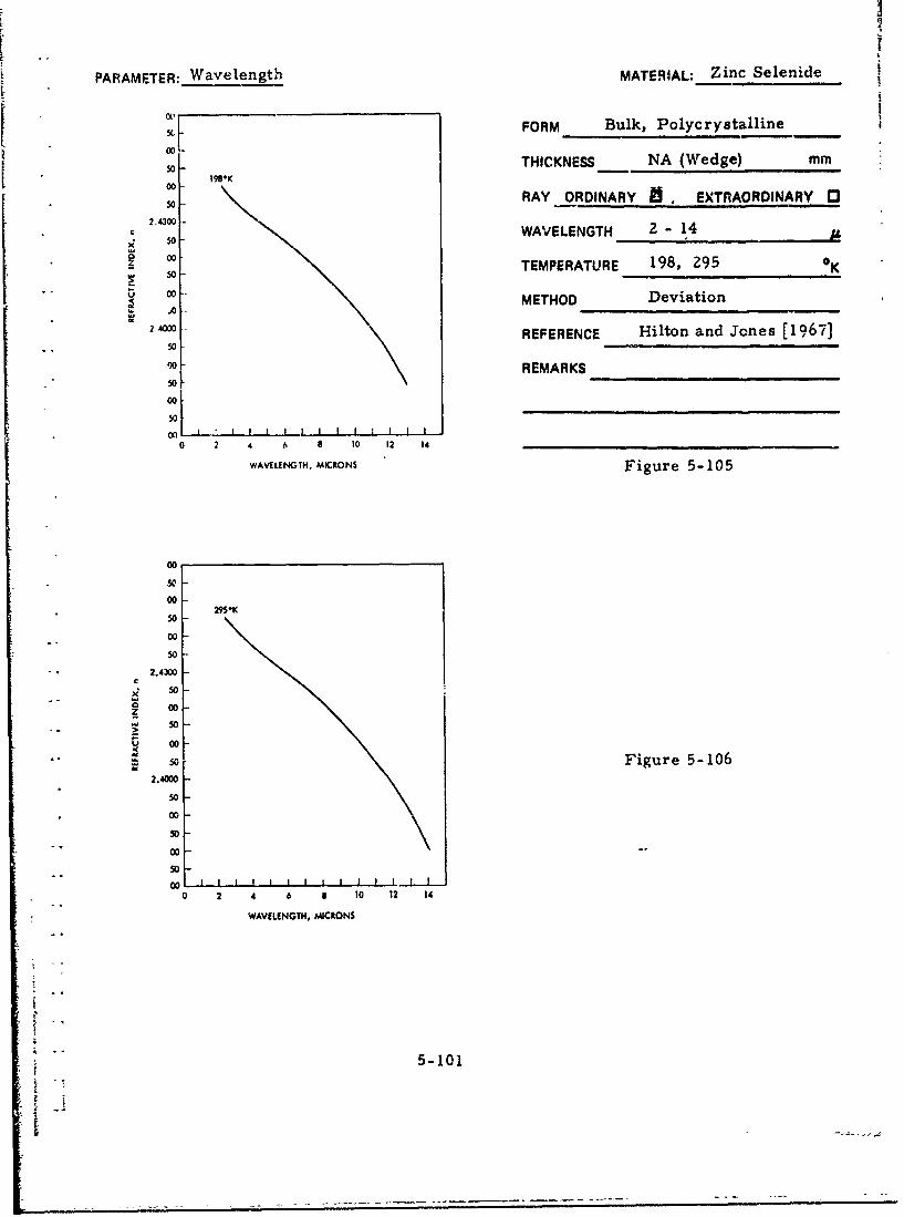
PARAMETER: Wavelength MATERIAL: Zinc Selenide
FORM Bulk, Polycrystalline
5o THICKNESS NA (Wedge) mm195*K
00 RAY ORDINARY i EXTRAORDINARY 050-
2.4300 - WAVELENGTH 2 14, 50 -
00 0Z TEMPERATURE 198, 295 K
u 00ooMETHOD Deviationo000 2REFERENCE Hilton and Jones (1967]
00 REMARKS
50
00
So0 2 4 6 0 10 12 14
WAVELENGTH, MICRONS Figure 5-105
00
50
00
50
2
.0 1 00
50S • 2.43D0
"00
"" • 5o Figure 5- 106
50s -500
00 I I I I I II I I I
0 2 4 6 a 10 12 14
WAVELENGTH, MICRONS
5-101

PARAMETER: Wavelength MATERIAL: Zinc Selenide
FORM Bulk, ')olycrystalline
THICKNESS Not stated mm
RAY ORDINARY , EXTRAORDINARY 0C
x WAVELENGTH 1.0 - 202.6
-flAN*4•:• 2.4 "A0
22 i. I I i , TEMPERATURE 298 K2 4 6 1 1o 12 14 16 11 20
WAWLUNOGN, MCRONS METHOD Not stated
REFERENCE Kodak [1967]
REMARKS IRTRAN-4 material
Figure 5-107
Wavelength, Refractive Wavelength, Refractive(Microns) Index, n .Microns) Inder, n
1.0000 2.485 7.0000 2.423
1.2500 2.466 7.2500 2.422
1.5000 2.456 1.5000 2. 421
1.7500 2.450 7.7500 2.419
2.0000 2.447 8.0000 2.418
2. 2100 2.444 8.2500 2.417
2.5000 2.442 8.5000 2.416
2. 75i0 2.441 8.7500 2.415
3.0000 2.440 9.0000 2.413
3.2500 2.438 9.2500 2.411 Table 5-413. 5000 e. 437 9.5000 2.410
3.7500 2.436 9.7500 2.409
4.0000 2.435 10. 0000 2.407
4.2500 2.434 11.0000 2.401
4.5000 3.433 12.0000 2.394
4.7500 2.433 13.0000 2.386
5.0000 2.432 14.0000 2.378
5.2$06 2.431 15.0000 2.370
6.59,4 I 2.430 16.0000 ý. 361
5. 750 0 A. 429 17.0000 2.352
6.0000 2. .Q28 18. Z000 2. 343
6. 25C0 2.426 19. 000C 2. 333
$. 5000 I 2.425 z2. 0000 2.323
6.7500 2.424 -
5-10.
5-102.

L
PARAMETER: Wavelength MATERIAL: Zinc Selenide
FORM Bulk, Polycrystalline
25 THICKNESS Not stated mm90*K
"20 RAY ORDINARY fl EXTRAORDINARY CC Z
. t5 WAVELENGTH 10 1250
, Uo _...-._ 90, 3014) Kr z ,0L TEMPERATURE K
. METHOD Reflection
.REFERENCE Hadni, et al. (29510)
0 25 50 75 100 125 150
WAVELENGTH, MICRONS REMARKS
Figure 5-108
251
300*K
.20
- 0
So Figure 5- 109
x
10 -
"0 25 50 75 100 125 ISO
WAVELENGTH, MICRONS
5-103.•';

PARAAiETEP: Wavelength MATERIAL: Zinc Selenide
I.K FORM Bulk, Polycrystalline
THICKNESS Not stated mm
RAY ORDINAR, (Z, EXTRAORDINARY [
IWAVELENGTH 28 - 67
STEMPERATURE 77, 290 0K0
% METHOD Reflection
10--• iREFERENCE Hadni, et al. (34136)
REMARKS
• ! • - 'Calculated by Kramera-Kronig Method- f0 .
S9 250 300 Figure 5-0110
WAVE NUMU, c;A"
t I I__I_____ _________
7 50 40 J3
WAVELIENGIM, MICRONS ftwMIs$1 with lmolesbaCWayrl• I Ji Akodsi Veriog
,.k, 77-K
10 Ik, ,M*K Calculated by Lorentz Oscillator Theory
% Figure 5-111
C
I°I0 0
" M 250' 300
WAVE NUMJ•M, CM"SI I I I L t J
67 50 40 33
WNVOALENGT, MICRONSi ~5-1041

- PARAMETER: Wavelength MATERIAL: Zinc Selenidc
FORM Filn
Wavelength, THICKNESS - 0. 8 x 10O 3 mm(Microns) Refractive Index, n
• .. .RAY ORD;NARY B. EXTRAORDINARY 00.8 2. 50
". WA,%7LENGTH 0.8 - 1.9 A0.9 2.47
1. 0 2.46 TEMPERATURE KK?98 K
1. 1 2. 45 METHOD Interference1.2 2. 442.43 REFERENCE Fischer, et al. (15559,.3 2. 43...
1. 5 2.42 REMARKS Evaporated film on
1.7 Ž. 41 borosilicate glass substrate.
>1.9 2.40
Table 5-42
5-105
LI

PARAMETER; Temperature MATERIAL: Zinc Selenide
FORM Bulk, Single Crystal
THICKNESS Not stated mm
U -- -oo.* RAY ORDINARY i , EXTRAORDINARYD
;: 4' _ _ __ _ _ _WAVELENGTH 20-85
10 ITEMPERATURE 100, 300 K
6 'I METHOD Reflection
__, __' __-______ REFERENCE Manabe, et al. (28526)20 30 40 5o 60 70 80
REMARKSWAVEteNGTH, MICRONS
Figure 5-112
-5-106
t --

PARAMETER: Temperature MATERIAL: Zinc Selenide
00r FORM Bulk, Polycrystalline5o
00 THICKNESS NA (Wedge) mm50
198K
00 - RAY ORDINARY 13, EXTRAORDINARY 0350
?. 430 WAVELENGTH 2 - 14x" 50
00 TEMPERATURE 198, 295 KZ Ko50-0 o METHOD Deviation
50 Hlo n oe lb'2 400 REFERENCE Hilton and Jones [1967]
5000 REMARKS
som0050
O01
0 2 4 6 8 10 12 14 -
WAVELENGTH. MICRONS Figure 5-113
00soo50
00.-295"K50
00
.50
-, 2.4300C
500o Figure 5-1140I 00
"- - 5o ",0
2.4000
50
00
* 50
- ~ 00SL•=• • O L-,,.J I ! II I I I I I I i .j
0 2 4 6 8 10 2I 14
WAVELENGTH, MICRONS
5-107

PARAMETER: Temperature MATERIAL:_Zinc Selenide
FORM Bulk, Polycrystalline
25 THICKNESS Not stated mm
C Z RAY ORDINARY , EXTRAORDINARY 13WI
SWAVELENGTH 10 - 125
z 10 TEMPERATURE 90, 300 0K
... METHOD Reflection
45 k5 REFERENCE Hadni, et al. (29510)0 5 50 75 100 125 150
WAVEENGTH, MICRONS REMARKS
Figure 5-115
25300*K
".20
0U Figure 5-116
10
5I.. ..... _ __ _ __ _
0 25 50 75 100 125 150
WAVELEU'TH, MICRONS
5-108
|I
: =: .

PARAMETER: Temperature MATERIAL: Zinc Selenide
10 1'7 FORM Bulk, Polycrystalline -
THICKNESS Not stated mm
8 FrRAY ORDINARY 1[, EXTRAORDINARY E
t 20 WAVELENGTH 28 - 67Z/ k, 290 "K
I5[~ I' TEMPERATURE 77,290 K
METHOD Reflection
0 ,o y REFERENCE Hadni, et al. (34136)
- I REMARKS ITRAN-4 material- I n.290*Kr
5 2 - Calculated by Krar.-iers-Kronig
method.
o 0 3n, Figure E-117150 200 250 300
WAVE NUMIIER, CM"1
. I IA
3 50 40 33
WAVELEN G TH, MICRONS CbMishoil with pArmiss•le
CaWISM*)I960 Ak6&wf Verial
k, 77"K
-~ ~k, 290-K
Z Calculated by Lorentz Oscillator Method
0 Figure 5-118
10 5
F--n, 290'K--
I in, 77"K
0 0 :ISO 200 250 300
• •WAVE NUMBER, CM'"1
• 67 50 40 33
VýVLNH MICON 5-109
----- -
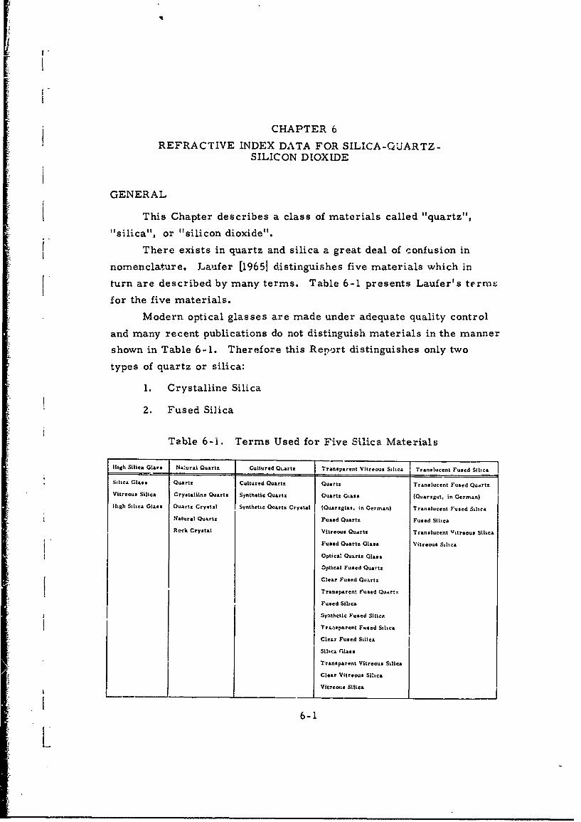
ii
CHAPTER 6
REFRACTIVE INDEX DATA FOR SILICA-QUARTZ-SILICON DIOXIDE
GENERAL
This Chapter describes a class of materials called "quartz","silica", or "silicon dioxide".
There exists in quartz and silica a great deal of confusion in
nomenclature. Laufer [19651 distinguishes five materials which in
turn are described by many terms. Table 6-1 presents Laufer's terms
for the five materials.
Modern optical glasses are made under adequate quality control
and many recent publications do not distinguish materials in the manner
shown in Table 6-1. Therefore this Report distinguishes only two
types of quartz or silica:
1. Crystalline Silica
2. Fused Silica
Table 6-i. Terms Used for Five Silica Materials
High Silica Glass Natural Quartz Cultured Q%.artz Transparent Vitreous Silica Translucent Fused Silica
Silica Glass Quartz Cultured Quartz Quartz Translucent Fused Quartz
Vitreous Silica Crystalline Quartz Synthetic Quartz Quartz Giass (Quarzgut. in German)
ligh Silica Glass Quartz Crystal Synthetic Quartz Crystal IQuarzglas. in German) Translucent Fused Silica
Natural Quartz Fused Quartz Fused Silica
Reck Crystal Vitreous Quartz Translucent Vitreous Silica
Fused Quartz Glass Vitreous Silica
Optica' Quartz Glass
Optical Fused Quartz
Clear Fused Quartz
Transparent Fused Quartz
Fused Silica
, ynthetic Fused Silica
Tr.ansparent Fused Silica
Clear Fused Silica
Silica (Ilass
Transparent Vitreous Silica
Clear Vitreous Sihca
Vitreous Silica
6-1

SILICA, CRYSTALLINE
INTRODUCTION
Crystalline silica, also called a-quartz, is the only crystalline
form of silica that is stable below 846*K at atmospheric pressure. It
is a uniaxial birefringent crystal (hexagonal) that has a resistivity of
approximately 1015 ohm-cm at 30001K. Crystalline silica exhibits
strong optical absorption due to lattice absorption bands between 5 and
37 microns in wavelength, becoming transparent again from 50 to
1000 microns, as shown in Figure 1-4. The transmittance in the far
infrared has led to the use of this material as window material in this
region and for eliminating high-order radiation in far infrared grating
spectrometers. Other applications of crystalline silica include
piezoelectric crystals and electromechanical transducers.
Most high grade natural crystalline silica is obtained from Brasil.
Material of similar quality has been synthesized by hydrothermal
growing. The physical properties of crystalline silica are summarized
in rable 1- 1.
DATA
The data for crysta'line silica are listed in Table 6-2 ami
detailed in Figures 6-1 to 6-15 and Tables 6-3 to 6-6. Table 6-3
represents a composite of early data for the near infrared region.
The wavelengths covered in the data are from 1 to 600 microns and
all data were gathered at room temperature. In additional to the
"refractive index for the ordinary ray, a great deal of refractive index
data for the extraordinary ray is included. In general, the data show
-• good agreement in refractive indices.
PRECEDING PAGE BLANK6-3

Table 6-2. List of Crystalline Silica Data
Wavelength
(Microns)
Figure Table no ne Form Crystal From To Parameter
6-1 X Bulk 7 14 Wavelength
6-2 X Bulk 5 14 Wavelength
6-3 X Bulk 6 33 Wavelength
6-4 X Bulk 6 33 Wavelength
6-5 X X Bulk 6 35 Wavelength
6-3 X X Bulk 1 4 Wavelength
6-6 X Bulk 80 300 Wavelength
6-7 X Bulk 80 300 Wavelength
6-8 X Bulk 27 63 Wavelength
6-9 X Bulk 27 63 Wavelength
6-10 X Bulk 50 500 Wavelength
6-11 X Bulk 50 500 Wavelength
6-12 X Bulk 40 500 Wavelength
6-4 X Bulk 70 300 - Wavelength
6-5 X X Bulk 100 300 Wavelength
6-13 X Bulk 180 600 Wavelength
6-14 X Bulk 180 600 Wavelength
6-15 X Bulk 180 500 Wavelength
6-6 X Bulk 337 337 Wavelength
6-4
I.

PARAMETER:_Wavplength MATERIAL: _.r.stalli n,
FORM Bulk
THICKNESS not stated mm
RAY ORDINARY M, EXTRAORDINARY 1C._ _ _
WAVELENGTH 7-14
"4 TEMPERATURE -298
2 METHOD Reflection
•o 9qoo 1¢0o 10o 1200 130o 140o REFERENCE Simon (398Z7)
WAVE1NUJCM'I REMARKS Crystal cut perpendicularI I I I I L.L..J
14.3 12.5 11.1 10.0 9.1 0.3 7.6 to the optical axis
WAVULNG•H. MICPONS
Figure 6-1
"THICKNESS 0.025 - 0.05 mm
3 RAY ORDINARY * EXTRAORDINARY 0
WAVELENGTH 5-14
Z TEMPERATURE - 298 oK
METHOD Interference
I REFERENCE Ramadier-Delb'es (39712)C' ' I I I I I -
4 5 6 7 6 9 1011 12 13 14 REMARKSWAVELENGTH, MICRONS
1 Pvbksebsis f~seiews do PIW•
Figure 6-2
i66-5

Silica,
PARAMETER: Wavelength MATERIAL: Crystalline
FORM Bulk
THICKNESS 0.030 mm
.IC RAY ORDINARY E , EXTRAORDINARY 13
WAVELENGTH 6-33
3 TEMPERATURE 298 OK
I I ,ý , METHOD Reflection3W 4W0 6w0 IM0 10W 1200 1400 1600
WAVE NU•MR,CM" 1 REFERENCE Haefele (40240)! I I I I I I l
33.3 25.0 16.7 12.5 10.0 8.3 7.1 6.2 REMARKSWAVELENGTH, MICRONS
Figure 6-3
Published with petu~ssieft
6 911ci532
.IC
3W 4M 6w 8 1000 1200 1400 100 Figure 6-4
WAVE NUIM.t Cm"1
33.325.0 16.? 12.5 10.0 8.3 7.i 6.2
WAVELENGTH, MICRONS
6-6

Silica,PARAMETER: Wavelength MATERIAL: Crystalline
FORM Bulk
8THICKNESS 0.0262 m1, CIC RAY ORDINARY 19, EXTRAORDINARY U
0 0 WAVELENGTH 6-35 A
-o- TEMPERATURE 297 0K
EIIC6I METHOD Reflectivity4
2 REFERENCE Spitzer & Kleinman (186t,6)0 .L _ .
6 8 10 12 14 16 18 20 2^ 24 26 28 30 32 34 REMARKS v-.quartzWAVELE.GTH, MICFONS
THE REFRACTIVE INDEX OF QUARTZ FOR THE ORDINARY RAY ) ANDTHE EXTRAORDINARY kAY k) AS OVATIN D ۥ,M T2"E__ _ __ _ANALYSIS OF THE REFLECO :VITY.
Figure 6-5
THICKNESS Not stated mm
Refractive Index
Wavelength, i RAY ORDINARY , EXTRAORDINARY 9(Microns) no no Ref
1.0417 1.53442 1.54317 a WAVELENGTH 1.0-4.2 At1.0973 1.53366 1.54238 a TEMPERATURE 29 1I. 1592 1.53283 1.54152 a
1.2288 1.53192 1.54057 METHOD Not stated1.3070 1.53090 1.53951 a
* 1. 3685 1.53011 1.53860 a REFERENCE Smakula [195211.3958 1.52977 1.53832 a
1.4792 1.52865 1.53716 a REMARKS References for this Table:
1.5414 1.52781 1.53630 a
1.6146 1.52679 1.53524 a
1.6815 1.52583 1.53422 a
1.7437 1.5248 1.53319 a (a) Carvallo, A., Compt. rend.1.9457 1.52184 1.53004 a Vol. 126, (1898), p. 728.2.0531 1.52005 1.52823 a (b) Kohlrausch, F., "Praktische2.60 1.50966 - b Physik, " Vol. II, 18th Ed.,
B. G. Teubner, Leipzig, (1943),3.00 1.49953 - b p. 528.3.50 1.48451 - b (c) Rubens, H., Wied. Ann., Vol. 54,4.00 1.46617 - b (1895), p. 488.4.20 1.4569 - c
Table 6-3
6-7

Silica.
PARAMETER: Wavelengith MATtiIIAL: Crystalline
FORM Bulk2.16 - ___________
2.16 THICKNESS -1 mm|.1.OPTK AXIS
C2.14 -RAY ORDINARY ,EXTRAORDINARY
T WAVELENGTH 80 - 3002.1 -S2.12 TEMPERATURE 298 OK
S' ~METHOD T ransmig=,sion
REFERENCE Roberts & Coon (18253)2.0 6
140 100 82 REMARKS Brazilian QuartzWAVELENGiH, MICRONS
II I I ,, ,,-,
50G 10,000 15,00O
(WAVE NUMA) 2 , CM"Figure 6-6
E II OPTIC AXIS2.20
- I
2.16 r Figure 6-7
2.:4II05000 10,000 15,000
(WAVE NUMA)••2, CM"2
II I I
140 100 32
WAVELENGTH, MICRONS
6-8

Silica.PARAMETER: Wavelength MATERIAL: Crystalline
FORM Bulk
3.00 THICKNESS 0.0766 m
RAY ORDINARY EXTRAORDINARY
2.90 ORDINAR RAY WAVELENGTH -.. • - 6 3
TEMPERATURE "301 o
2.W METHOD Interference
REFERENCE Russell & Bell (28888)2.40 )L
REMARKS
2.20
[cc, Figure 6-8
L qII . I
"I50 v. 2!3 300 350 400
WAVE NUMBER, CM1SI t
- 62.5 41.7 33.3 25
WAV.V:LN TH. MICAONS
3.00 /2.80
EXTRACRDINARY RAY
2.6 Figure 6-9S2.60
2.00
III I150 200 250 300 350 400
•- ~WAVE NUMBE.R- CM"i
62.5 4,.7 3.3 25 6-9
WAEEGH IRN

rSilica,
PARAMETER: Wavelength MATERIAL.' Crystalline
FORM Bulk
THICKNESS 0. 255 mm
RAY ORDINARY U EXTRAORDINARY "
Refractive Index, WAVELENGTH 100 - 300
Wavelength, Ordinary Ray Extraordinary Ray TEMPERATURE 300 KMirn (no) (no METHOD Inte rfer ence
REFERENCE Berman & Zhukov (36032)165-240 Z. I I *- 0. 03(b) 2. 16 0 . 02(b)
L _REMARKS
(a) crystal cut.. to optical axis
(b) crystal cut I1 to optical axis,
(X cut)
Table 6-5
6-10

PARAMETER: Wavelength MATERIAL: Cryrstalline
2.125 FORM Bulk
THICKNESS 1. 0497, 4. 7873 mm2.120
0
o RAY ORDINARY M , EXTRAORD)INARY U
2.115 WAVELENGTH 180-600
TEMPERATURE 301 *KS2.10- ORDNARY RAY -
METHOD Interference
2.105 ne( -20 30REFERENCE Russell & Bell (28888)0 20 30 40 5
WAVE NI.MBER, CM" RMARKS__I l l I I I I I I "
1000 500 333 250 200 1S2
WAVELENGTH, MICRONS
Determination of the extrapolated, zero-frequency ordinary- and Figure 6-13extraordinary-ray refrac... nd.cts of quartz. The extrapohltcdvalues. n*(0) = 2. 1062 and ne{O) = 2. 1538, have an experimeidtl uncer-tainty of 0.001, which is much larger than is apparent from the con-sistency of the data
"2.165
re2.160r EXTRAORDINARY RAYi f-2..5
n.- 2.15.3II
2,150-
""L- Figure 6-14F 145 1 I I I I I I0 20 30 40 50
WAVE NU.AER, CM"1
-. , ~._]I I I I I Ii I
io00 500 333 250 200 182
WAVElUNGTH, MICRONS
6-11LL

SilicaPARAMETER: Wavelength MATERIAL: C ',ysta~line
[3FORM Bulk
2.30 THICKNESS 0.48 mil
RAY ORDINARY IM EXTRAORDINARY [3WAVELENGTH 180 - 500
000 ,• , 0 00• .: TEMPERATURE -298 OK
2.10
METHOD Interference
2.00 _ _ _REFERENCE Chamberlain (40179)2. 0 30 40 50 60
WAVEN MIR, CM" REMARKS *run 1; 0 run 2; 4 run 31 -I I IJ
SOD 250 167
WAVELENGIH, MICRONS
Woo w .ft Figure 6-15
THICKNISS 3-7 mm
Wavelength, RAY ORDINARY * a EXTRAORDINARY QMicrons Refractive Index, n
WAVELENGTH 337 I
337 2. 132 h 0. 026 TEMPERATURE -298 *K
METHOD Interference
REFERENCE Chamberlain & Gebbie(40177)
REMARKS Use of CN maser a0
radiation source.
Table 6-6
6-12

iI --ilca,
PARAMETER: Wavelength MATERIAL: Crystalline
2.220 FORM Bulk
%THICKNESS 1. 0497, 4. 7873 mm
2.200.�- E C RAY ORDINARY B EXTRAORDINARY U
2.100 WAVELENGTH 50 - 500 ,TEMPERATURE 301 K
METHOD Interference2.160
REFERENCE Russell & Bell (28888)
"'= = REMARKS ....______________
-. 2.140 REMARKS
"2 120
SjE.M Figure 6-10
0 • Lo 0D 150 200 250
SWAVE NUJMBER, CM"I
it
"- , II I I I
182 100 62.5 30
WAVELENGTH, MICRONS
2.270
2.250
2.230
"x Figure 6-11- 2.210
-2.1%)
2.i70
2.150I I I0 50 100 150 200 250
WAVE • IJMER, c.CM"
II I III
"" 182 100 62.5 50 6-13
WAVELENGTH, MICRONS

SilicaPARAMETER: Wavelength MATER;AL: Crystalline
FORM Bulk
2.30 THICKNESS -o.6 mm
2.20 ,PAY ORDINARY 19 EXTRAORDINARY 13
2.10 WAVELENGTH 40 - 500* CRYSTALLINE QUARTZ,S~0.619 mm
2.00 cCRYSTALLINE QUARTZ TEMPERATURE -298 KO.504 mm
Sgo _ METHOD Interference50 100 150 200
WAVE N'JMAEt, CM"C REFERENCE Qeick (39706)t I I I
2W 100 62.5 50 REMARKSWAVELENGTH, MICRON$
PublilShe with POVA160msaC•rIht*lt II *rlsgsr. Wvlsg ..
Figure 6-12
THICKNESS 1, 2 mm
Wavelength, RAY ORDINARY U EXTRAORDINARY 0(Microns) Refractive Index, n R O ,
WAVELENGTH 70 i 300
70-300 Z. 2 k 0.02TEMPERATURE 298
METHOD Interference
REFERENCE Poiusot, et a!., (40710)
REMARKS
Table 6-4
6-14
SILICA, FUSED
INTRODUCTION
Fused silica is considered to be a glass and in common with other
glasses, its transmission spectrum shows a deep absorption near
2. 8 microns and poor transmission at longer wavelengths (Figure 1-5).
The absorption in this region is caused by O-H stretching bands.
Fused silica is used in innumerable technical applications because of
its optical, thermal, mechanical and electrical properties.
Classically, fused silica is prepared by fusion of crystalline silica.
Material of very high pruity can be made by hydrolysis of silico.l
tetrachloride at high temperature where the product, (fused silica) is
deposited on a substrate.
The physical properties of fused silica are summarized in
Table 1-1 and its transmission in the far infrared is plotted in Figure 1-6.
DATA
The data for fused silica are listed in Table 6-7 and their temper-
ature range is plotted in Figure 6-16. Refractive index spectra for
bulk fused silica are offered in Figures 6-17 to 6-23 and Tables 6-8 to
6-15; similar data for film fused silica are prcvided in Figures 6-24
and 6-25. Comparison of the data shows good agreement to approxi-
mately eight microns with a wider spread in data at longer wavelengths.
The meager film data show good agreement with bulk data. The tem-
perature dependence of the refractive index of bulk fused silica is thesubject of Table 6-16 and Figure 6-26, while film data are shown inFigure 6-27. Figure 6-27 indicates an increase in refractive index with
temperature at wavelengths below nine microns, and the opposite effect
at longer wavelengths. The effects of ultraviolet radiation or simulated
Apollo mission space environment are the subjects of Figure 6-28 and
Table 6-17, respectively.
6-15

Table 6-7. List of Fused Silica Data
Wavelength (micronsFigure Table n, k Form Crystal From To emarks Parameter
m- I6-17 n Bulk o. 3. 5 Wavelength6.18 n Bulk 0 ..- ,Wvelength
6-8 n Bulk 0. 7 3. 7 Wavelength6-9 n Bulk 0.4 1.08 Wavelength6-10 n Bulk 0. 7 3. 7 Wavelength
6.11 n Buik 1.0 1. 5 Wavelength
6*IZ .i Bulk 1.0 3.4 Wavelength6-I 3 n Bulk 1. 0 2. 6 Wavelength
6-19 n Bulk 7.7 12 Wavelength6-20 n Not Stated 6 100 Wavelength6-21 n Not Stated 30 2000 Wavelength
6.14 n Bulk 50 400 Wavelength
6-22 n Bulk 85 200 Wavelength6-23 n Bulk III 600 Wavelength
6.15 n. k Bulk 2000 2000 Wavelength6-24 n Film 0.2 1. 6 Wavelength6-23 n Film 7 11 291-1543'K Wavelength
6-16 n Bulk 1.0 3.4 299-1 101 1K Temperature6-26 dn/dT Bulk • 0.2 4.0 293-303 Temp..--ture6-27 n Film 7 11 291-1543 Temperature6-28 n Film 0. z 1.5 UV Light •.ediation
6-17 n Bulk 0.23 3.4 Space RadiationRadiation
1000
Z 100
0 200 600 800 1000 12W
TEMKtPATUE, OK
Figure 6-1.6. Wavelength and TemperatureRange of Fused Silica Data
6-16

PARAMETER: Wveegt,
FORM Bulk1.400-
THICKNESS NA (Prism) mm
RAY ORDINARY 13 EXTRAORDINARY E"1.4650
WAVELENGTH 0.4 - 3. 5
TEMPERATURE 297 0KC 1.4500
METHOD Deviation_z
REFERENCE Rodney and Spindler (39714)
"1•4350 REMARKS Heraeus B quartz
Most probable values of refractiveESTIMATED
1.4200 VAWES I '\ indices of pure fused-quartz at 297*K
for various wavelengths, computed"from equation (1)
-- _Figure 6-171.4050 70.3 0.5 1.0 2.0 5.0
WAVELENGTH, MICRONS
*1
20.008777808 84.06224Equation (1) n = 2. 979864 + -0.007808 84. 062Xz-0O.010609 96. 00000 -- 2
where X = wavelength in microns.
6-17

PARAMETER:.Wavelength MATERIAL: Silica, Fused
FORM Bulk
1.54 THICKNESS NA (Prism) mm
RAY ORDINARY * , EXTRAORDINARY 03
1.520 WAVELENGTH 0. 2 - 3. 5_
TEMPERATURE 293 OK
1.5m METHOD Deviation
REFERENCE Malitson (21758)
'3 140 REMARKS The dispersion equation (2)
is valid for interpolation to five
91.4 decimal places over the measuredwavelength range.
Figure 6-18
1.420
1.400 I I I0 0.2 0.4 0.6 1.0 2.0 4.0
WAVELENGTH, MICRONS
Equation (2) n2 -1 6961663K . 40794Z6k .2+ 0.8974794X
u (0. 0684043)Z X - (0. 1162414) x (9
where X = wavelength in microns.
6-18

PARAMETER: Wavelength MATERIAL: Silica, Fused
FORM Bulk
THICKNESS NA (Prism) mm
RAY ORDINARY I EXTRAORDINARY 0
WAVELENGTH 0.7 - 3.7 p
TEMPERATURE 293 0 K
METHOD Deviation
REFERENCE Malitson (21758)
REMARKS Computed refractive index
for three products
Table 6-8. Computed Refractive Index and Residuals
Wavelength Spectral Computed C-D-G-E5
Corning No. 7940 Dvnasil General Electric No. 1516 6 66
microns source index residual X 10 residual X 10 residual X 10 residual X 13
0.706519 He 1.455145 + 5 + 10 + 12 + 7
0.852111 Cs 1.452465 • 5 + 8 + 3 + 5
0.894350 Cs 1.451835 4 5 + II + 5 + 10
1.01398 Hg 1.450242 + 8 + 6 + 3 + 6
1.08297 He 1.449405 - 5 + 8 + I + 9
1.12866 Hg 1.448869 + I + 7 + 8 + 9
1.3622 Hg 1.446212 - 12 - 6 - 14 - 12
1.39506 Hg 1.445836 + 4 - I + 4 3
"1."4695 Cs 1.444975 - 5 + 3 + 9 S 10
1.52952 Hg 1.444268 + 2 + 8 + 6 0
1.6606 TCBb 1.,42670 - 20 - 14 - 19 - 1i
1.681 Polyc 1.442414 4 6 - 2 - 10 + 8
1.6932 Hg 1.442260 0 4 7 6 + 11.70913 Hg 1.442057 4 3 0 + 3 - I
1.81307 Hg 1.440699 21 - 7 7 + 6
1.97009 Hg 1.43b;: I + I + 6 + 12 + 12
2. 0581 He 1.437224 4 3 9 - 11
2.1526 TCB 1.43576Q - 29 - 22 - 25 - 24
2.32542 Hg 1.432928 - is - ^- 3 - 6
2.4374 TCB 1.430954 - 24 23 - 21 - 14
3.2439 Poly 1.413118 + 32 + 21 + 29 + 25
3.2668 Poly 1.412505 + 25 4 20 + 30 + 25
3. 3026 Poly 1.411535 + 25 + 32 + 30 + 28"3.422 Poly 1.408180 + 20 4 40 4 42 + 37
3. 5070 Poly 1.405676 - 16 - 26 20 - 10
3. 5564 TCB 1.404174 - 24 - 27 - 29 - 18
3.7067 TCB 1.399389 - 19 - 22 - 14 -9
Average of absolute ,alhes of residuals 10.5 11.9 12.2 11.7I I I
a Reelduale for arlthmetical-rnean table of values compiled from experimental data of Corning (C).Dyuatil (D). and General Electric (G. E. ).
-e b rCB 1 1. 2, 4 - Trichlorobentene.c Poly =Polystyrene. 6-19

PARAMETER:-Wavelength (Cont'd from preceding page) MATERIAL: Silica, -Fused
Table 6-9
Intracompany Comparison of Refractive Index Variation
Product
Corning No. 7940 Dynasil General 6.lectric No. 151Wavelength, residual X ,06 residual X 106 residual X 106
(Microns) 1 2 3 4 1 z 3 4 1 2 13 4
0.4047 11 26 24 20 4 27 21 21 11 1iz -12 14
0.4861 16 27 16 21 5 29 19 21 7 15 - 7 12
0.5461 14 24 22 17 5 33 25 16 it 12 -13 12
0.5893 12 27 23 27 0 18 20 22 12 13 - 8 12
0. 6563 12 23 19 19 1 27 22 23 13 30 - 7 14
0.7065 17 28 20 18 2 31 23 23 13 15 -11 17
0.8944 11 26 22 19 3 31 • 19 25 13 12 - 8 13
1.014 16 21 20 20 6 30 26 22 14 t3 -II 14
1.083 15 24 25 25 7 35 25 25 13 16 - 9 12
Av. An 13.5 24.9 20.0 21.6 3.5 27.4 20.4 20.5 11.3 12.9 - 9.6 13.2
NOTE: Numbered columns under each brand indicrte individual specimens. The residuals are differ-ences in the sixth decimal place of index between measured values and those computed by dispersionEquation (2). Each n is an average for the 18wavelengths which were used. (See Figure 6-18 forEquation (2).
6-20
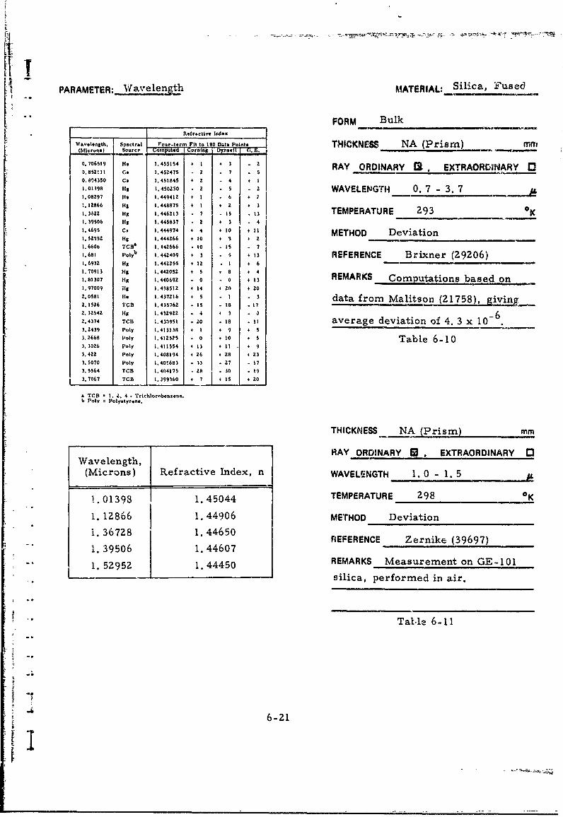
t-LIIt
PARAMETER: __avelength MATERIAL:; Silica, Fused
FORM BulkRefractive Index
Wavelength, Spectral F.ur-term Fit to 1,0 ODta Points THICKNESS NA (Prism) mm(Microns) Source' o utd cning I 3n i G, E. -
0.706519 He 1.455154 + 1 3 z RAY ORDINARY ! , EXTRAORDINARY O_.__11_ _ Cs 1.45_47_ - 2 -_7 - 5
0.84350 Cs 1.451845 4 2 4 + I
1.O198 fi 1.45025o0 5 2 z WAVELENGTH 0.7 - 3. 7 jI1.08297 Hs 1.449412 + I - 6 + 7!. 12866 HA 1.448875 I + Z 4 31.3622 Hg 1.446213 - 7 . Is . 13 TEMPERATURE 293 K1. 39506 Hi 1.445837 Z + 3 - 41.4695 Cs 1.444974 + 4 + 10 + II METHOD Deviation1.52952 Hg 1.444266 + 10 + 8 4 21.660b TCBa 1.44Z666 - O 1to - 71.681 Poly
6 1.442409 + 3 3 + 13 REFERENCE Brixner (29206)
1.6932 Hg 1.44Z255 + 12 I + 6 -1.70913 Hi 1.442052 + 5 8 o o1.81307 Hg 1.440692 - 0 - 0 + 13 REMARKS Computations based on1.97009 Hi 1.438512 + 14 4 20 + 202.0581 Ile 1,437216 + 5 -i - 3 data from Malitson (21758), giving2.1526 TCn 1.435762 IS 18 i 17
2542 Hg 1.432922 - 4 4 3 a dva n62.4374 TCI1 1.433951 - 20 18 - 11 average deviation of 4. 3 x 10-3.2439 Poly 1.413138 + I + 9 + 5
3.2668 Poly 1.412525 - 0 + 10 + 5 Table 6-103. 3026 Poly 1.411554 + I3 I I I + 9
3.422 Poly 1.408194 + 26 + 28 + 23
3. 5070 Poly 1.,40!•683 - 13 -27 1 7
3.5564 TCB 1.404175 28 30 193.7067 TCB 1.399360 + 7 + 1 20
a TCB a I. 2. 4 - Trichlorobenzene.b Poly : Polystyrene.
THICKNESS NA (Prism) mm
RAY ORDINARY W , EXTRAORDINARY E3Wavelength,
(Microns) Refractive Index, n WAVELENGTH 1. 0 - 1. 5
1.01393 1.45044 TEMPERATURE 298 OK
1. 12866 1.44906 METHOD Deviation
i.36728 1.44650 REFERENCE Zernike (39697)
L.39506 1.44607i. 52952 1. 44450 REMARKS Measurement on GE-101
-. -silica, performed in air.
Tatle 6-11
6-21

PARAMETER: Wavelength MATERIAL: Silica, Fused
Refractive IndexFORM Bulk
Wa.velength Refractive Index, n(Microns) 299K 744K 1101 THICKNESS NA (Prism) mm
1.01398 1.45039 1.45562 1.45960 RAY ORDINARY A , EXTRAORDINARY 01.12866 1.44903 1.45426 1.458201. 254* 1.44772 1.45283 1.45700 WAVELENGTH 1. 0 - 3.4
1. 36728 1.44635 1.45140 1.455491.470* 1.44524 1,45n3l 1.45440 TEMPERATURE 299 - 1101 o1. 52432 1.44444 1.44961 11.45352 METHOD Deviation
1.660* 1.44307 1.44799 1.451741. 701 1.44230 1.44733 1.45140 RL;ERENCE Neu, et al. (40260)
1.981* 1.43863 1.44361 1.447342. 262* 1.43430 1.43933 1.44306 REMARKS Corning Code 7940 silica2.553* 1.42949 1.43450 1.43854
3.00* 1.41995 1.42495 1.42877
3.245* 1.41353 1.41893 1.42243
3.3711 1.40990 1.41501 1.41915 Table 6-12
bn = 23 x 10-5 (experimental erý'or)
* Wavelength det.rmination by narrow band inter -ference filter.
THICKNESS not stated mm
Wavelength, Refractive Reference RAY ORDINARY I EXTRAORDINARY 0(Microns) Index, n . E
WAVELENGTH 1.0 -2.6 Ad
1.028 1.450 a
1.196 1.448 b TEMPERATURE 291 OK
1. 370 1.446 b METHOD not stated1.560 1.444 b REFERENCE Smakula [1952]
1.722 1.442 c
1.870 1.440 b REMARKS References for this Table:
2.010 1. 438 b (a) Carvallo, A. , Compt. rend. ,
2.145 1.436 b Vol. 126, (1898), p. 728.
2. 270 1. 434 b (b) Muller, C. and Wetthauer, A. ,
2.390 1.432 b Z. Phys. , Vol. 35, (1933), p. 559.2. 50 1. 430 b (c) Sifford, J. W. , Proc. Roy. Soc.
• sVol. 70, (1902), p. 329.2.595 1.428 b Table 6-13
6-22

PARAMETER: Wavelength MATERIAL: 5iiica, Fused
3.6 FORM Bulk
3.43.2 THICKNESS 6.o mm
3.0 RAY ORDINARY , EXTRAORDINARY 0
2.8
2. - WAVELENGTH 7. 7 -ZS+ 2.6
2.4 TEMPERATURE -298 0*K€ 2.2 -
S20METHOD Reflectance2 2.0 -N,
1 1.8 - REFERENCE Cleck (27331)
"1.6 - REMARKS Corning Code 7940 silica1.4 \
1.2 -
1.00.8 - • .
0.8I- Figure 6-19
0.4
0.2
0 I I t I
7 8 9 10 II 12
WAVELENGTH, MICRONS
1300 1100 900 am THICKNESS Not stated mm
RAY ORDINARY M , EXTRAORDINARY [
WAVELENGTH 6 - 100 0A
_ TEMPERATURE 298 *K
METHOD Reflectance
REFERENCE Miter (Z1593, 34239)SI I Ii !
"1500 1oo 5oo 0 REMARKS
WAVE NUMBER, CM°1
I I I I ____________________________
6.7 10 20 33 50 100
WAVELENGTH, MICRONS
Figure 6-20
" +f "" Ipbmishal with emImtlsl6lt
Uppwight4DWISAkodwil Ver1"
6-23

PARAMEY ER: Wavelengh MATERIAL: Silica, Fused
FORM Not stated
THICKNESS Not stated mm
RAY ORDINARY U , EXTRAORDINARY 02.0
WAVELENGTH 30 - 2000
.TEMPERATURE -298
METHOD Reflection
1.S REFERENCE Block, et al. (36747)p I I I IIII I IIIII1 I I I111 1 I
40m Io 100 10 REMARSKS
WAVLItNGTM, MCONS
Figure 6-21
THICKNESS 50-904 25 mm (Bulk) mm
ZZO-400. 0. Z56 mm
Wavelength, Refractive Index, RAY ORDINARY M , EXTRAORDINARY C3
(Microns) n WAVELENGTH 50 - 400
50 2.07 TEMPERATURE -298 °K
90 1.94 METHOD Reflection, Interference
220 1.89REFERENCE Bogens and Zhukov (35268)250 1. 92
270 1.89 REMARKS
330 1.92
400 1.92
Table 6-14
6-24
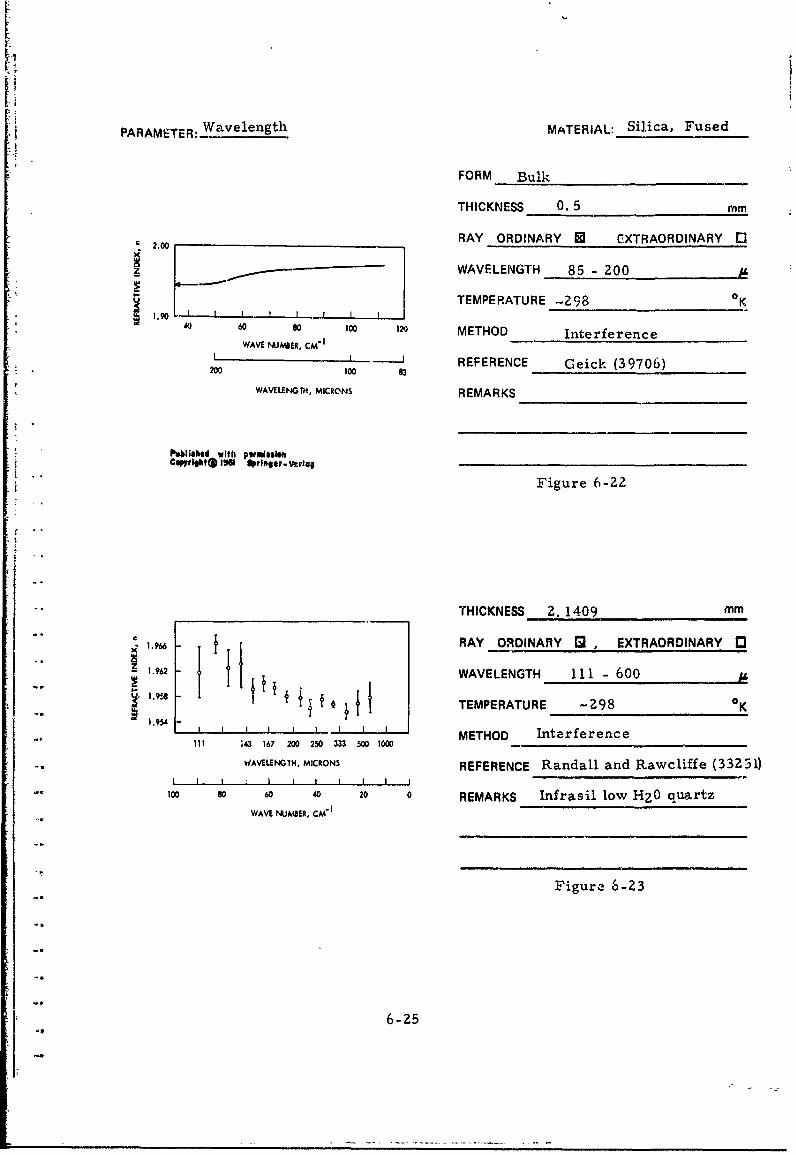
Wavelength MATERIAL: Silica, Fused
FORM Bulk
THICKNESS 0. 5 mm
_ __.ooRAY ORDINARY 0 E CXTRAORDINARY E0c*2.00
WAVELENGTH 85 - 200
TEMPERATURE -298 0
1.90 I40 60 80 1oo 120 METHOD Interference
WAVE NUMIER, CM"1
-I _ I REFERENCE Ceick (39706)200 100 83WAVELENGTH, MICRONS REMARKS
Published with pwmissleeSCwl~rlgt( 8I W prlneev-verlqj
Figure 6-22
-"_THICKNESS 2. 1409 mm
"1. 966 RAY ORDINARY , , EXTRAORDINARY "
"1.962 - WAVELENGTH 111 -600
1.956 I' TEMPERATURE -298 0K-. , !.1.95*
1.95 I I I I I METHOD Interference"Ill ;43 167 200 250 333 500 1000
WAVELENGTH, MICRONS REFERENCE Randall and Rawcliffe (33231)I I I I I I I
too 8o 60 40 20 0 REMARKS Infrasil low HZO quartz
WAVE NUMBER, CM-
Figure 6-23
6-25

PARAMETER: Wavelength MATERIAL: Silica, Fused
FORM Bulk
THICKNESS 18-, 40 mm
RAY ORDINARY 83 EXTRAORDINARY r3
WAVELENGTH 2, 000
Wavelength, Refractive Extinct-on TEMPERATURE -298 oKMicrons Index, n Coefficient, k x 103
-METHOD TransmissionZ00 1.95 o oo081 0.56* 0,06
20000.08 0 56 0. 6 1 REFERENCE Dianov and Irisova (41423)
REMARKS Sample consisted of two
wedges.
Table 6-15
6-26

PARAMETER:, Wavelength MATERIAL: Silica, Fused
FORM Film
THICKNESS not stated mm1.6
RAY ORDINARY •], EXTRAORDINARY "1
x "_WAVELENGTH 0. 2 - 1.5z
1_ =.5 TEMPERATURE -298 OK
METHOD Reflection
1.4 .- _ REFERENCE Cox, et al. (17066)0.2 0.6 1.0 1.4
WAVELENGTH, MICRONS REMARKS Film produced by electron
bombardment of fused silica,
evaporated on fused silica substrate.
Figure 6-24
THICKNESS 5 x 10"4 mm3.0
2.5 RAY ORDINARY 3 EXTRAORDINARY E3
. WAVELENGTH 7- 111373* TEMPERATURE 291 - 1543 oK
1.5 1473 /,
1.0 / METHOD Reflection
0.5 91 REFERENCE Neuroth (40354)673, 8730
01 1 tO 7 REMARKS78 9 10 1
WAVELENGTH, MICRONS
Published with pfffmssifoCaftrigltI g pringer-Varlv Figure 6-25
6-27

PARAMETER:_Temperatre MATERIAL:- Silica, Fused
FORM BulkWavelength. Ra1rfctiv* Index Refrwclve Index.
(Micron@) 299"( 744 .K O 1. o1.< Kx 0° THICKNESS NA (Prism), mm
0. Z1021 I.52034 1. U908 +19.6 1.53524 +19.30.,23783 1.51496 1.52332 +18 8 1.52985 .13.6 RAY ORDINARY AI, EXTRAORDINARY 030.2407 1.51361 1. S201 +16.9 1. 52832 +18.3
0.2465 1.50970 1.51774 +18.1 1. 52391 +17.7
0.24827 1.0o865 1.51665 +18.0 1.S2289 +17.8 WAVELENGTH 1.0 - 3.40.26520 1.50023 15076. +16.6 1.51351 116. 5
0.27528 1.4961S 1. 501V7 +16.0 1.50899 +16.000.28035 1.49425 1.50143 +16.2 I.S0691 +15.8 TEMPERATURE 299 - 1101 oK0.28936 1.491it 1.49818 +15.7 1. 035t +15 4
0.29673 1.48892 1.49584 +11.6 1.50112 +15.2
J.i02Is 1.48738 1.49407 +15.1 1.49942 +15.0 METHOD Deviation0.3130 1.48462 1.49126 +14.9 1.49641 +14.7
0.33341S 1.48000 1.48633 +14.2 1.49135 +14. REFERENCE Neu et al. (40360)0. 365P2 1.47469 1.48089 +14.0 1.48563 +13.6 REFERENCE6-Neu, et al. (40360)
0.40466 1.46978 1.47375 +13.4 1.48033 +73.2
0.43584 1.46685 1.47248 +12.7 1.47716 '12.9 REMARKS Corning Code 7940 silica0.54607 1.46028 1.46575 +12.3 1.47004 112.2
0. 5780 1.45899 1.46429 +11.9 1.46870 +12. I
1.01398 1.45039 1.45562 +11.8 1.45960 +11.5
1.12866 1.44903 1.45426 +11.8 1.45820 +11.4
1.254 1.44772 1.45283 +11.5 1.45700 +11.6
1.36728 1.44635 1.45140 111.4 1.45549 11.4
1.470 1.44524 1.45 .! +ti 4 1.45440 +11.4
1. 52952 1.44444 1.44,61 +11.6 1.45352 +11.3 Table 6-161.660 1.44307 1.44799 +11.1 1.45174 +10.8
1.701 1.44230 1.44733 +11.3 1.45140 +11.3
1.981 1.43863 1.44361 +11.2 1.44734 +10.9
2.262 1.43430 1.43933 +11.3 1.44306 +10.9
2.553 1.42949 1.41450 +11.3 . 43854 +11.!
3.00 1.41995 1.42495 +11.2 1.42877 +11.0
3.245 1.41353 1.41893 +12.2 1.42243 +11.1
3.37' 1.40990 1.41501 +11.5 1.41915 +11.5
Wav. length determination by narrow.bandwidth interference filters.
THICKNESS NA (Prism) mm
RAY ORDINARY 6 , EXTRAORDINARY 03
WAVELENGTH 0. 2 - 4.020.0
TEMPERATURE 293 - 303 OK1.0
METHOD Deviation
REFERENCE Malitson (21758)" 14.0
12.0 REMARKS
10.0 -
8.0 I I I I J0 0.2 0.4 0.6 1.0 2.0 4.0 6.0
WAVLENGTH., MICRONS Figure 6-26
6-Z8
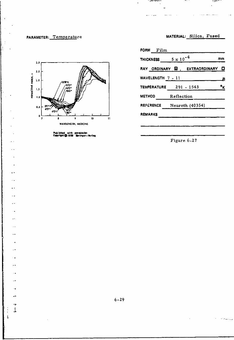
PARAMETER: Temperature MATERIAL: Silica, Fused
FORM Film
3.0 THICKNESS 5 x 10"4 mm2.5 RAY ORDINARY A. EXTRAORDINARY 01
€ 2.5 e
•.o ...... WAVELENGTH 7 - 11- ,127$*K /S/1373"1.5 1473 * TEMPERATURE 291 - 1543 K
1.0 METHOD Reflection
0.5 291.1 REFERENCE Neuroth (40354)470673. 1OB73
07 I111* REMARKS7 9 10
WAVEILNGTH, MICRONS
Poklished with permissionC@Pytlliglkt@i 19iM Sprilni-er. lelsi
Figure 6-27
6-29
.2

PARAMETER: Radiation (UV) MATERIAL: Silica, Fused
FORM Film, Amorphous
THICKNESS (1-5) x 10" mm1.7
RAY ORDINARY 0 , EXTRAORDINARY 1
R U$123)WAVELENGTH 0.2 -1. 5C KoRIuv (512o3) Z 8O
S1.6 ~EXI•UE1.6 TEMPERATURE -298
METHOD Ref lcrtion
1t.5 REFERENCE Cox, et al. (17066)
REMARKS Film produced by evaporation1AULK MJED ,SILICA
1.4 __ of SiO in the presence of oxygen.0.2 0.6 1.0 1.4
WAVELENTH, MCRONS Data include refractive index beforeand after ultraviolet irradiation.
Figure 6-?8
6-30

PARAMETER:. Radiation (Space) MATERIAL: Silica, Fused
___FORM Bulk
Refractive Index, n
Wavelength, THICKNESS NA (Prism) mm* Irradiated An
(Microns) Non-irradiated 30 day dose x R0D_____=RAY ORDINARY IU1, EXTRAORDINIARY
0. 230Z1 1.52034 1. 52037 + 3
0.23783 1.51496 1. 51502 + 6 WAVELENGTH 0.2 - 3.40.2407 1.51361 1.51363 + 2
0. 2447 1.51081 1.51075 - 6 TEMPERATURE 299 0K
v. 2465 1. 50970 1. 50974 + 4
0. 248Z7 1.50865 1.50869 + 4 METHOD Deviation0.26520 1.50023 1. 50028 + 5
0.2700 1.49839 1.49831 - 8 REFERENCE Neu, et al. (40360)0.27528 1.49615 1.49616 + 1
0. 28035 1.49425 1.49429 + 4 REMARKS Corning Code 7040 silica.0,28936 1.45121 1.49123 + 2
0. 2930 1.49021 1.49023 + 2 Radiation simulating 30 day exposure0.29673 1.48892 1.48895 + 3
0. 30215 1.48738 1. 48741 + 3 for Apollo mission.0. 3130 1.48462 1.48460 - 2 10 -z -10.33415 1.48000 1.47997 - 3 Proton flux: 3 x 10 cm sec
0. 36502 1.47469 1.47473 + 4 ( <2 MeV).Electron flux: 2. 5 X 10¹²
0.40466 1.46978 1.46981 + 3 cm-2 see-] (1 MeV). Ultraviolet:
0.43584 1.46685 1,46689 + 4 0. 5461 watt-cm-i (0. 22 - 0. 4 fL)0.54607 1.46028 1.46025 - 3 Atmospheric pressure: Pmin0.5780 1.45899 1.45900 + I I0-10 Torr)1.n1398 1.45039 1.45040 + 1 Table 6-171. 12866 1.44903 1.44901 - 2
1. 254* 1. 44772 1.44760 - 12*1. 36720 1.44635 1.44633 - 2
.470* 1.44524 1.44513 - 11*1. 52452 1.44444 ,.44445 + I
1. 60* 1.44307 1.44296 . ll1.701 1.44230 1. 44228 - 2
1.981* 1.43863 1.43859 - 4*
2.262* 1.43430 1.43426 - 4*
2. 553* 1.42949 1.42939 - 10*
3.00* 1.41995 1.41962 - 33*
3. 245* 1.41353 1.41351 - 2*
3.37* 1.40990 1.40997 + 7*
6n = 23 x 10"5 (experimental error)
*Wavelength determination by narrow band interferencefi6ters.
"" ~6-31
CHAPTER 7
REFRACTIVE INDEX DATA FOR FLUORIDESv AND SELECTED CERAMICS
r This Chapter provides refractive indices and extinction coefficients
for the following fluorides and ceramics which are grouped together on
the basis of their high temperature capabilities: ralcium fluoride,
magnesium fluoride, aluminum oxide including ruby and sapphire, and
r• magnesium oxide.
17-1IiI.
I 7-1
I.f
i
L!
CALCIUM FLUORIDE
INTRODUCTION
Calcium fluoride offers high and uniform transmission over the
range from the ultraviolet region to approximately ten microns (Fig-
ures 1-7 and 1-9) and this constant transmission makes this material
very desirable for wide spectrum optical applications. Rather pure
single crystal calcium fluoride is found in nature and is called
"Fluorite" or "Fluorspar. " Calcium fluoride of similar purity, but of
larger dimensions, has been produced by controlled freezing of purified
molten calcium fluoride after an initial scavenging with lead fluoride.
Fluorspar is widely used in iron foandry operations, the manufacture
of primary aluminum and magnesium, as source of fluorine cherni-
cals, for the production of glass and enamels, and innumerable other
uses.
The physical properties of calcium fluoride are summarized in
Table 1- 1.
DATA
A list of refractive index data for calcium fluoride is provided in
Table 7-1 and the temperature range of the data is plotted in Figure
7-1. The wavelength dependence of the rcfractive index and some
extinction coefficients for bulk single crystal material are presented
in Figures 7-2 to 7-9 and Tables 7-2 to 7-6 and for polycrystalline
I material in Figure 7-10 and Tables 7-7 and 7-8. The data reveal good
agreement in refractive index is discernible between single and poly-
crystalline material. Only in the "Reststrahlen" region of the spec-
trum (near 38 microns) is there a major disagreement in refractive
I[ index between authors. The temperature dependence of the refractive
index is covered by Figures 2-3 and 7-11 as well as Tables 7-9 and 7-10.
|I PRECEDING PAGE BLANK7-3!

Table 7-1. List of Calcium Fluoride Data
Wavelength
(Microns)
Figure Table n. k Form Crystal From To Remarks Parameter
7-Z n Bulk Single 0.75 1.1 Wavelength
7-3 n Bur':. Single 0.8 9.0 Wavelength
7-4 n Bulk Single 0.9 9.4 Wavelength
7-5 n Bulk Single 0 8 9.8 Wavelength
7-2 n Bulk Single 1 10 Wavelength
7-6 n Bulk Single 0 85 9.7 Wavelength
7-3 k Bulk Single 6 9 Wavelength
7-4 n, k Bulk Single 15 48 Wavelength
7-5 n. k Bulk Single 34 43 Wavelength
7-6 n Bulk Sinble 10 80 Wavelength
7-7 k Bulk Single 10 80 Wavelength
7-8 n Bulk Single 8 15 Wavelength
7-9 n Bulk Single 55 400 80, 300'K Wavelength
7-7 n Bulk Polycryst. 0.59 5.3 Wavelonsth
7-8 n Bulk Polycryst. 1 11 Wavelength
7-10 n Bulk Polycryst. 1 11 Wavelength
7-9 dn/dT Bulk Single 0.9 6.S 330-354"K Temperature
7-10 dn/dT Bulk Single 0.85 9.7 2920K Temperature
7-11 n Bulk Single 55 400 80, 300'K Temperature
l000
'.I 100
S 10
I --..,,L - • '! I I I I l I I I
0 200 400 6W0 O 1000 1200
TUMiIRATUU, "K
Figure 7-1. Wavelength and Temperature Range
of Calcium Fluoride Data
7-4
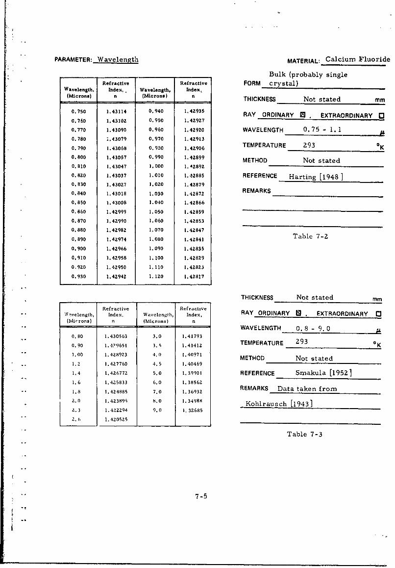
PARAMETER: Wavelength MATERIAL: Calcium Fluoride
Bulk (probably single
Refractive Refractive FORM crystal)Wavelength, Index, Wavelength, Index,(Microns) n (Microns) n THICKNESS Not stated mm
0.750 1.43114 0.940 1.42935 RAY ORDINARY I EXTRAORDINARY 00.760 1.43102 0.950 1.42927
0.770 1.43090 0.960 1.42920 WAVELENGTH 0.75 - 1. 1
0.780 4.43079 0.970 1.42913
0.790 1.43068 0.930 1.42906 TEMPERATURE 293 0 K0.800 1.43057 0.990 1.42899 METHOD Not stated0.810 1.43047 1.000 1.42892
0.820 1.43037 1.010 1.42885 REFERENCE Harting [1948 10.830 1.43027 1.020 1.42879
0.840 1.43018 1.030 1.42872 REMARKS
0.850 1.43008 1.040 1.42866
0.860 1.42999 1.050 1.42859
0.870 1.42990 1.060 1.42853
0.880 1.42982 1.070 1.42847
0.890 1.42974 1.080 1.42841 Table 7-2
0.900 1.42966 1.090 1.42835
0.910 1.42958 1.100 1.42829
0.920 1.42950 1.110 1.42823
0. 930 1. 42942 1.120 1.42817
,_THICKNESS Not stated mm
Refractive I Refractive" Vvelength, Index, Wavelength, Index, RAY ORDINARY [ , EXTRAORDINARY C3(Microns) n (Microns) n
" _ _-WAVELENGTH 0.8 - 9.0
0.80 1.430563 3.0 1.41793
0.90 1.4?9651 3.9 1.41412 TEMPERATURE 293 0g
"1.00 1.428923 4.0 1.40971 METHOD Not stated1.2 1.427760 4.5 1.40469
1.4 1.426772 5.0 1.39901 REFERENCE Smakula [1952]1.6 1.4Z5833 6.0 1.385621.8 1.4Z4885 7.0 1.3693Z REMARKS Data taken from
S2.0 1.423895 8.0 1.34988 Kohlrausch [1943]2.3 1.422294 9.0 1. 32685
2.0 1.420525
Table 7-3
"" ~7-5

PARAMETER: Wavetength MATERIAL: Calcium Fluoride
, t,.l11., .a•..lp.,1 ,hT 11ta IFORM BulktM rttl d ! , MI~ rll) I
J(m. . THICKNESS Not stated mm4l. 4x4n 1 4199n A. "n1o0 I. 1lI91
1. n1 411 l.41NA 4 1. AM ll I. • 111in
1. 01tI4 1.4.l41 1.'141.6 1.41411 RAY ORDINARY W , EXTRAORDINARY 03i. 110 i. 4,111 1. 4.12,121 1.417411
1. 171. 1.447'99 !.,,',.. p4.14 WAVELENGTH 0. 9 - 9.41. 2-M 1.41742 1.2411 1.411,10
1. 11. 1.4 1-41 J.4000 1.414417 TEMPERATURE 293 K1. 471 ) 1.4, W .44 J. Nt ) ,. .1 141 Il1,
I. -,71 q+ 1.4d W 91. 1. 1,101, 1. 41 1191,.1,41" 1.41%;14 4. Onf 1. 4096,1 METHOD Not stated1. . ? ,#l! I. 42 %(Q£ 4. Itil 1. 40114'7
1. ft$fll1.444,, 4. 91,11, 1.44,Z REFERENCE Ballard (12539)I. 14W.1 l 1. 4Z414 4. 4(141,16
T"I.-'illn 1. 4A41W 4. I.lOhn 1. 40017 REMARKSl.'1141 1.1VA411 4.7141, 1. 4li I I
1.111.44 .1441401 4.,.reinn 1 . 4111 It,
A. I*14142 1. 4Z 1141 (. i)of) I. * (1'9'I_
1'. 0641,l 1. 4Z 1,7 m$. 1O .1, AZZ'+
1. 1. 4t Pit.421 . 8191, I. 11?711
.dll 1. 4•1•11 I.. 48424 I. 17AL4
. 1,.1l I.421',K 7.11r,1 I. 1.I,,I,,• Table 7-4Z. 4011 1. 4Z 141 7.66,19h I . 2;,70
I.4•4.t 1.41nflhl . tuOm1 I. 14440
A. 7-11 1.419n*,
Je .¢live ter• ive
W..Xli.., I •s. w .ol•.. .10, THICKNESS NA (Prism) mm(Mt. n,,,te) ii (MI. r,,,n. n
n.. Nil 1. 4 1 2*A I. J 1.40 1.4 RAY ORDINARY EI , EXTRAORDINARY r'
go. kt/ I1. 4 W ilt= 4.141-i I. 41,1 Ili
n..44 ,.41,,I, 9.,1 1.11',1,% WAVELENGTH 0. fl - 9. 8m1.i2. I. 4•1914• 4. l I. * 1.4'1
II. 14.4 I 4277 k, 416 I. 1'l-14
0.,,n 1.4191-1%,. 14. 1.19,1, TEMPERATURE 297 OK11 -it I.40'l4% %. ft I. 110241
1..'.4 1.4A9 In I*..f n. 1.144, METHOD DeviationIl. I. I. 4111% I.. ;in I. 30119")
11, 'IN 1.40n11 I i. 40 I1 '7944
1.00 1.4116#111 ,.. ,U 171.01. REFERENCE Malitson (39194)1. to 0 . 1071 f. No I. M1ilt
1.4, 1.4461 .O 1. '1"M REMARKS Computed refractive1. 6n 1. 4W?79 7.211 1. 1Mill)9
1.110 1. 424144 7.410 I.31,191
1.0 1.44 I .,N% 1.7.IA4 index, based on observed data.Z. to 1. 491-, 7.40 1. 3S401
A. 40 1.4L 11,I N4. 0 1. I.ON4'114
Z.04 I. .4049 A. 0 134S44
1.14O 1.41911 1N.4n I. 34'06 Table 7-53. OC 1.44 X.60 1.3364S
3. 0 1.411,19 N.-O I. )3 169
3.40 1.41441t 9.00 1.39677
3.,0 1.41320 9.20 :. 3,161I,80 1.41147 9.40 1.3164)
4. #0 1.40963 9.60 I.31'01
4. 1.40770 9.110 1.30441
4.40 1.401167
7-6

PARAMETER: Wavelength MATERIAL: Calcium Fluoride
FORM Bulk, Single Crystal
THICKNESS NA, (Prism) mm1.44
RAY ORDINARY 0 . EXTRAORDINARY r31.42
C WAVELENGTH 1 - 10)z 1.40 ____________
.3 TEMPERATURE 297 K
6 1.36 METHOD Deviation
1.34 REFERENCE Malitson (391'14)
132 REMARKS Synthetic crystal1.30 2 , , ,
1 2 3 4 5 6 7 8 9 10
WAVLENGTH, MICRONS
Figure 7-2
Residual ,[(Observed-Cornput-ai x WI0'
MaterialComputed
Wav.elenth. Ind.., Synthetic Natural(Micron*) n o-c -
O. 8sz i. 43002 - 1 +4
0.8944 1.42966 0 +!
i., 9 1.42879 . o THICKNESS NA (Prism) mm1.3622 1.4Z691 +1 +8
1.3950 1.4267S +1 +6 RAY ORDINARY W , EXTRAORDINARY E0I.sz~s 1.42612 +4 +4,
2.7012 1.42531 +2 +42.81307 1.42478 0 +9 WAVELENGTH 1 - 101.97009 1.42401 +3 .3
.12, .42J3o0 , + 1EMPERATURE 297 OKS3354 1..42121 +3 -4
2.4374 2.42247 0 +2
3.3026 1.4,S62 0 +3 METHOD Deviation3.422 1.41467 +2 .2
3.7067 1.41398 -1 +, REFERENCE Malitson (39194)3. 706 l, 41ZZ19 +Z z,
4.258 2 .40723 +4 :4
5.01882 2.3 8 .73. REMARKS Comparison of narural and...o .,o 3 13 2.39 4 2 1 synthetic single crystals
6. z18 1.38200 .6 0
6.63306 1.37S65 0 +_
6.8559 1.37186 .8 .2
7.268 1.36443 +2 +7
7.4644 1.36070 .S +6 Table 7-68.663 2.33500 .4 +3
9.724 1.30756 +2 +5
7-7

PARAMETER: W velength MATERIAL: Calcium Fluoride
FORM Bulk, Single Crystal
THICKNESS 11il.7(6- 914 8 (15-.18I•) -T,
RAY ORDINARY U EXTRAORDINARY 0
=. 10.5 W AVELEN•GTH 6 -48 ..
w s TMPRATURE ~-298 °KSMETHOD 6-%1- Transmission;
S15-481L Reflection.REFERENCE Heilrnann (40178)
S0o6REMARKS Improved results over
earlier work, reported by Heilmann
[1961]
6 7 6 Figure 7-3WAVILENGTH, MICRONS
publishod with pWUissioIC~rllht•1965 llrlmler -Wer4q
.5
WX4
k2 Figure 7-4
2
Is 20 25 30 35 40 45
WAVILENGTH, MICRONS
7-8

PARAMETER: Wavelenbth (Cont'd from preceding page) MATERIAL: Calcium Flouride
n I'
10 \I
z\
0\z\
5\
0\
C I
k I
I
II
350
- kk
I -
u I
I I
_ I,
25 4
wAvELENGT, MICRONS
Figure 7-5
Nc'*e:---Results of Kaiser,et al (40176).
7-9

PARAMETER: Wavelength MATERIAL_ Calcium Fluoride
14_FORM .Bul Single Crystal
THICKNESS 0.1 - 5 mm12
RAY ORDINARY Q, EXTRAORDINARY ,310
I WAVELENGTH 10 - 80
TEMPERATURE -298 OK
METHOD Reflection
REFERENCE Kaiser, et al. (40176)
[2 REMARKS
010 20 30 40 !0 60 70 I6
WAWVLNGtH, MICRONS
Figure 7-6
14
Figure 7-7Uz
4
10 20 30 40 s0 40 70 80
WAVLENGTH, MkICNS
7-10

PARAMETER: Wavelength MATERIAL: Calcium Fluoride
FORM Bulk, Single Crystal
1.4 THICKNESS 0. 025 - 0.050 mm
1.3 - RAY ORDINARY !, EXTRAORDINARY C3C
SWAVELENGTH 8 15
1.2 TEMPERATU)RE -Z98 0K
Si METHOD Interference
i.I REFERENCE Ramadier - Delbles (39712)
REMARKS
8 9 ,0 , 12 13 14 1S 16
WAVELENGTH, MICRONS
Figure 7-8
3.2 r THICKNESS 0.3- 10 mm
3.1 - 0o 300,K
00oee 0K I' RAY ORDINARY *t, EXTRAORDINARY 0
_2.9 - WAVELENGTH 55 - 400
2.3 -// TEMPERATURE 80, 300 OK
2.7- METHOD Interference2.6
2.5 I I I REFERENCE Bosomworth (0Z9681)0 50 100 ISO 200
REMARKS Principal impurity
L I I I I I 10-100 pp.- of iron. Lines are basedoW 2o0 ,3 ,o1 so 50 on dielectric constant of an infinite
harmonic fluorite lattice.WAVELENG ;., MICRONS
Figure 7-9
7-11

PARAMETER: Wavelength MATERIAL: Calcium Fluoride
Wavelength, Refractive FORM Bulk, Polycrystalline
(Microns) Index, n THICKNESS Not stated mm
0.588 1.4339 RAY ORDINARY O . EXTRAORDINkRY 031.014 1.4289 WAVELENGTH 0.59 - 5.3
1.529 1.4262
1.970 1.4241 TEMPERATURE -298 *K
2. 325 1. 4222 METHOD Not stated
2. 674 1. 4200 REFERENCE Type IRG 12 material
3.303 1.4157
4.258 1.4072 REMARKS
4.59 1.40345.303 1.3952
Table 7-7
Refractive Refract;veWavelength, Index, Wavelength, Index,(Microns) (Microns) n
1.000 1.4289 5.7300 1.3892
1.2500 1.4275 6.0000 1.3856 THICKNESS Not stated mmI..5000 1. 4Z63 6.2500 1.3818
1.7500 1.4251 6.5000 1.3778 RAY ORDINARY , EXTRAORDINARY E2. 0000 1.4239 6.7500 1.37372.2500 1.4226 7.0000 1.3693 WAVELENGTH 1 - 112.5000 1.4211 7.2500 1.3648
2.7500 1.4196 7.5ooo 1.3600 TEMPERATURE 298 oK3.0000 1.4179 7.7500 1.3550
3. 5o00 1.4161 8.0000 1.3498 METHOD Not stated3.5000 1.4141 8.2500 1.3445
3.7500 1.4120 8.5000 1.3388 REFERENCE Kodak [1967]4.0000 1.4097 8.7500 1.3330
4. 2500 1.4072 9.0000 1.3269 REMARKS ITRAN-3 material4.50000 1.4047 9.2500 1.3206
4.7500 1.4019 9.5000 1.3141
5.0000 1.3990 9.7500 1.3073
5.2500 1.3959 10.0000 1. 3002
5.5000 1.3926 11.0000 1.2694 Table 7-8
1.2 Figure 7-10
S2 4 6 a 10 12
WAVUINGTH, MICRONS 7-12

PARAMETER: Temperature MATERIAL: Caicium Fluoride
FORM Bulk, Single CrystalTemperature Mean
Wavelength Coefficient, Temerature,(Microns) -(dn/dT) x 106 *K THICKNE$ Not stated
RAY ORDINARY I , EXTRAORDINARY I30.900 10.31 333. 1
1.200 •0.40 333.1 WAVELENGTH 0.9 - 6.5
1.25 10.29 TEMPERATURE 330 - 335 oK
1.30 10.18 333.5
2.0 9. 32 333.5 METHOD Not stated
3.16 8.81 332.6 REFERENCE Smakula [195Z]
4.2 8.3' 332.8
5.3 8.21 332.2 REMARKS Data taken from6.5 7.87 1 330.0 Liebreich [19111
Table 7-9
rComputed T•.mperaturtWavelength. Index, Coefficient.(Microns) n -(dn/d') x 106
0.85212 1.43002 10.6
0.8944 1.42966 10.61.01398 1.42879 I0.5 THICKNESS NA (Prism) mm1.39506 1.42675 9.9
1.52952 1.42612 9.6 RAY ORDINARY 0 , EXTRAORDINARY 01.701Z 1.42531 9.4
1.81307 1.42478 9.1 WAVELENGTH 0.85 - 9.71.97009 1.42401 8.9
2.1526 1.42306 8.7 TEMPERATURE Z9Z OK2.32542 1.42212 8.5
2.4374 1.42147 8.5 ,;ETHOD Deviation3.3026 1.41561 8.2
3.422 1.41467 8.1 REFERENCE Malitson (39194)3.5010 ,.41398 8.0
3.7067 1.41229 7.8 REMARKS Synthetic single crystal.4.258 1.40713 7.5
5.01882 1.39873 7. 3
5.3034 1.39520 7. Z
6.0140 1.38539 7.0
6.238 1. 38200 7.0
6.63306 1.37565 6.9
6.8559 1.37186 6.7 Table 7-107.268 " 36443 6.5
7.4644 1.36070 6.4
8.662 1,33500 6.0
9.724 1.30756 5.6
7-13

PARAMETER: Temperature MATERIAL: Calcium Fluo.' -.
FORM Bulk, Single Crystal3.2 -
3., oooo /3WOK THICKNESS 0.3 - 10 mm
3.0 000 .9 /K RAY ORDINARY M , EXTRAORDINARY D
2.9 WAVELENGTH 55 400
2.8-
2.7-- .0 TEMPERATURE 80, 300 oK
2.6- -0 METHOD Interference
2.50 50 100 1SO 2o REFERENCE Bosomworth (29681)
WAVE NUM, CM"1 REMARKS Principal impuritySi I I I I I
10-100 ppm of iron. LAines areWAVE"NGTH, MIJONS
based on dielectric constant of an
infinite harmonic fluorite lattice.
Figure 7-11
7-14

MAGNESIUM FLUORIDE
INTRODUCTION
Magnesium fluoride is prepared by the reaction of magnesium
oxide with hydrofluoric acid and as a byproduct from the reduction of
metal fluorides with magnesium in the manufacture of some metals.
Magnesium fluoride is used as flux in the metallurgy of magnesium
metal, as flux for porcelain and pottery, as phosphor in cathode ray
screens, as coating agent for titanium pigments, and in optics as
window material and antireflection coating on lenses.
The optical transmission of polycrystalline magnesium fluoride is
shown in Figure 1-9, and its physical properties are listed in Table 1-1.
DATA
Refractive index data for magnesium fluoride are listed in
Table 7-11 and consist only of one set of data for polycrystalline
material (Figure 7-12 and Table 7-12) and one data point for magnesium
"fluoride film (Table 7-13). This apparent lack of data in the literature
does not permit a comparison of results.
Table 7-11. List of Magnesium Fluoride Data
Wavelength
(Microns)
Figure Table n, k Form Crystal From To Parameter
7-12 n Bulk Polycryst 1.0 6.75 Wavelength
7-12 n Bulk Polycryst 1 9 Wavelength
7-13 n Film 2.0 2. 1 Wavelength
*Not Stated
"7-15

Mansium
PARAMETER: Wavelength MATERIAL: de
______ _______ _____FORM._ B.ulk, PolycrystallinieWavelength, Refractive Wavelength, Refractive F P
(Microns) Index, n (Microns) Index. n
1.0000 1.3778 4.0000 1.3526
1. 2500 1. 3763 4.2500 1. 3492 RAY ORDINARY _ , EXTRAORDINARY C-1.5000 1. 3749 4.5000 1. 3455
1.7500 1. 3735 4.7500 1. 3416 WAVELENGTH 1 - 92.0000 1. 3720 5.0000 1.3374
2. 2500 1. 3702 5. 2500 1. 3329 TEMPERATURE 298 0K2. 5000 1. 3183 5. 5000 1. 3282
2.7500 1. 3L63 5.7500 1. 3232 METHOD Not stated
3.0000 1. 3640 6.0000 1. 3179
3. 2500 1. 3614 6.2500 1. 3122 REFERENCE Kodak [19671
3. 5000 1.3587 6.5000 1.3063
3.7500 11.3558 16.7500 1 3000 REMARKS IRTRAN- 1 material
Table 7-12
S1.6
1 ,.4 IRIRAN I Figure 7-12
•- 1.2 I
2 4 6 8 to
WAVELENGTH, MKRONS
7-16

MagnesiumPARAMETER: Wavelength MATERIAL: Fluoride
FORM Film
Wavelength, THICKNESS -5 x 1.0 4 mmMicrons Refractive Index, n0
________--RAY ORDINARY • , EXTRAORDINARY 0"2 ~1. 36 WAVELENGTH -2 A
TEMPERATURE -298 OK
METHOD Transmission
REFERENCE Jenness (40476)
REMARKS Evaporated coating
on fused silica substrate.
Extraordinary ray neglected.
Table 7-13
7-17

F[
1"
" ALUMINUM OXIDE - CORUNDUM SAPPHIRE - RUBY
INTRODUCTION
Corundum is a naturally-occurring a-alumina, (Al 0 3), which
crystallizes in the hexagonal form. Pure curundum is fully trans-
I parent and water-white, and is called "white sapphire." Corundum
for optical applications is generally synthesized and called "sapphire."
1 Corundum crystals containing from approximately 0. 04 to 5 percent
chromic oxide in their lattices are called "ruby." The ruby's applica-
tions in optics are mostly in la ;er technology. The synthesis of
sapphire is commonly performed by means of the Verneuil or flame
- fusion process which is based on the fusion of the aluminum oxide
with heat from a hydrogen-oxygen source and growth at a controlled
]- temperature of approximately 2300°K. The light transmission
t - through sapphire is shown in Figure 1-8 and shows a useful region
between 0.2 and 5 microns. The infrared optical properties of
- corundum, sapphire and ruby are essentially identical, [Ref. Haefele
(9762)].
* Physical properties of sapphire are summarized in Table 1-1.
•- Uses for aluminum oxide include gems, jewel bearings, luminescent
* materials, abrasives and optics.
DATA
A list of data presentations for aluminum oxide is offered in
Table 7-14 and the wavelength- and temperature coverage is plotted
in Figure 7-13. The spectral dependence of the refractive index of
bulk corundum, sapphire and ruby is shown in Figures 7-14 to 7-22
and Tables 7-15 to 7-17 for ordinary and extraordinary rays with
inclusion of some extinction coefficients, The data show good
agreement among authors and materials. Data for amorphous films
are presented in Figures 7-23 and 7-24 with fair agreement of the
sparse data with bulk data. Table (-18 gives refractive index data as
a function of wavelength and anodizing potential, and it is apparent
PRECEDING PAGE B:04NK,7-19

that low anodizing potentials give high readings -more nearly
resembling the metal than the oxide. The temperature dependence
of the refractive index is covered by Figures 7-25 and 7-26 as well
as Tables 7-19 and 7-20.
Table 7-14,, List of Aluminum Oxide Data
Wavelength
(Microns)
Figure Table n, k Form Crystal From To Remarks Parameter
7-14 n, k Bulk Corundum 9 33 293"K Wavelength
7-15 n,k Bulk Corundum 9 33 1773*K Wavelength
7-16 n Bulk Sapphire 0.3 5.6 Wavelength
7-15 n Bulk Sapphire 2.0 3.6 Wavelength
7-17 n Bulk Sapphire 58 500 0-ray Wavelength
7-18 n Bulk Sapphire 58 500 E-ray Wavelength
7-19 n Bulk Sapphire 180 500 0 & E-rays Wavelength
7-16 n Bulk Sapphire 58 500 0 & E-rays Wavelength
7-20 n Bulk Sapphire 112 300 Wavelength
7-17 n Bulk Sapphire 167 500 0 & E-rays Wavelength
7-21 n, k Bulk Ruby 6 33 0-ray Wavelength
7-22 n, k Bulk Ruby 6 33 E-ray Wavelength
7-1, n Film Atmorphous 1. 5 15 Wavelength
7-23 n Film Amorphous 0.2 i.6 318°K, 5730K Wavelength
7-24 n Film Amorphous 15 S7 Wavelength
7-25 n, k Bulk Corundtm 9 33 293*K Temperature
7-26 n, k Bulk Corundum 9 33 1773"K Temperature
7-19 n Bulk Sapphire 0.56 4.0 296 - 1973*K Temperature
7-20 dn!dT Bulk Sapphire 4 4 292 - 297°K Temperature
7-20

10
"II[.
I. I___I__$ I I __ -L•_ .J__I
0 4w0 Boo Ilý 16M0 2000
T .IWIPATURE, *K
t Figure 7-13. Wavelength and Temperature Rangeof Aluminum Oxide Da~ta
72
1.!
I._ __
LtiL4
i
I-

AluminumPARAMETER: Wavelength MATERIAL: Oxide-Corundum
FORM Bulk, Single Crystal
THICKNESS Not stated mm20IF 'AL2C* 3 RAY ORDINARY 63l EXTRAORDINARY 0
T.293K k WAVELENGTH 9 33Ut 10 n _ _ _ _ _ _ _ _ _ _ _ _
TEMPERATURE 293, 1773
-/
S-.. -METHOD Reflection0300 500 700 900 1100
WAVE NUMUR, CM"1 REFERENCE Piriou (29797)
I 1 i i i 1 1 REMARKS33 20 14 1I 9.1
WAVELENGTH, MICRONS
PIhbli1•ed with permissioencopyrivAt) 1966 Masson of Cle.
Figure 7-14
10' 8 a-AL2 0 3 EIC
w T 1773-9 k
r- Z 4
2- - Figure 7-15
0200 50 0 90' 1100
WAVE NUMIUR, CM1'
I I l I I I I l
33 20 14 II 9.1
WAVELENGTH, MICRONS
PRECEDING PAGE BLANK
7-23

AluminumPARAMETER: Wavelength MATERIAL: Oxide-Sapphire
FORM Bulk, Single Crystal
THICKNESS NA (Prism) mm
1.760 RAY ORDINARY U , EXTRAORDINARY 0
WAVELENGTH 0.3 - 5.6
C 1.740 TEMPERATURE 297 0K
METHOD Deviation!.7w 0
REFERENCE IMalitson (17008)
1.60 REMARKS
0.2 11.4 0.6 1.0 2.0 4.0 6.0 Figure 7-16
WAVEUNGTH, MICONS
THICKNESS 1.6, 3.2 mm
Wavelength, RAY ORDINARY . , EXTRAORDINARY C(Microns) Refractive Index, n
WAVELENGTH 2.0, 3.6
2.0 1.65 TEMPERATURE .-298 *K
3.6 1.60 METHOD Transmission
REFERENCE Jenness (40476)
REMARKS Values estimate-. from LiF
coating data
Table 7-15
7-24

AluminumPARAMETER: Wavelength MATERIAL: Oxide-Sapphire
3.300FORM Bulk, Single Crystal
ORDINARY RAy
tic THICKNESS 1.0 mm3.260
"° RAY ORDINARY I, EXTRAORDINARY
3.220 WAVELENGTH 58 - 500
co TEMPERATURE 301 0K
_ 3.10 - METHOD Interference
REFERENCE Russell & Bell (28755)
3.140 REMARKS
3.100
Figure 7-173.060 I I I
0 50 100 150 200 250
WAVE NUM&ER, CM'1I I I I I
LO 200 100 67 50
WAVELENGTH, MICRONS
3.640
EXTRAORDINARY %
3.600 I
S/
S3.560 Figure 7-18_z
Z3.520
3.440
3.400 I I0 50 100 15O 200 250
WAVE NUMI(R, CM"". I I I I I I
500 200 100 67 50• WAVELENGTH, MICRONS 7-25

rIAluminum
PARAMETER. Wavelength (Cont'd from preceding page) MATERIAL: Oxide-Sapphire
3.065 3.3
coS3.075 - z21 3.425
K%
i3.095 - 3.415-
S•""••-- %o ) "3.4W0S3.0M - 3.405-
Figure 7-19
3.105 3.995 1 1 1 l
50 40 30 20 0
WAVE I*JMhER, CM"1
II I I I I I Ii I
182 200 250 333 500
WAVELENGTH, MICRONS
Wave N mrber Wavelength, Refractive Indicesa
cm (Microns) no ne ne - no
20.2 3.0688 3.4111 0.3423
25.2 3.0698 3.4129 0.3436
30.2 330 3.0704 3.4134 0.3430
35.3 3.07Z0 3.4163 0.3443
40.3 3.0740 3.4187 0.3447
45.4 3. 0/52 3.4232 0.3480
50.4 zoo 3.0770 3.4260 0.3490
55.4 3.0795 3.4294 0.3499
60.5 3.0822 3.4334 0.3512
6S. 5 3.0843 3.4391 0.3548
70.6 142 3 0870 3.4444 0.3574
75.5 3.0906 3.4510 0.3604
80.6 3.0941 3.4569 0.3628
65.7 3.0902 3.4645 0.3643
90.7 3.1019 3.4689 0.3670
q5.8 3. 1060 3.4766 0. 3706 Table 7- 16100.8 100 3. 1103 3.4836 0.3733
105.8 3.1147 3.4908 0.3761
110.9 3.11)8 3.4993 0.3795
115.9 3.1249 3.5081 0.3832
120.9 83 3.1304 3.5185 0.3881
126.0 3. 1357 3.5279 0.3922
131.0 3. 1422 3.5375 0.3953
136.1 3. 1485 3.5508 0.4023
141.1 71 3.1549 3.5612 0.4063
146.1 3. 1623 3.5746 0.4123
151.Z 3. 1696 3,5856 0.4160
156.2 64 3.1765 3.6042 0.4277
161.3 3.1854
166.3 3.1921
171.3 3.2018
176.4 57 3.2113
AThe total estimated probabie error of the measured
values of the refractive indtces is *0. 002 except at trequen-cies less than 25 cm-
1 and greater than 150 cm-1 where the
error may be somewhat greater.
7-Z6

Aluminum
PARAMETER: Wavelength MATERIAL: Oxide-Sapphire
FORM Bulk. S Cnrie Q.ystal
WAVELENGTH, MJCRONS THICKNESS 1. 0 m112 129 155 220
3.11 29 5 2 RAY ORDINARY 2 , EXTRAORDINARY n
3.io WAVELENGTH 112 - 300 .,
S3 09 TEMPERATURE ,'298 OK
z3 08 METHOD Transmission
307 REFERENCE Roberts & Coon (1825_/
3.06 REMARKS
3.05IIS8000 6WO 4000 2000 0
WAVE NU4ER, CM-2
i Figure 7-20
THICKNESS 1.0 mm
Wavelength, Refractive Index, RAY ORDINARY E , EXTRAORDINARY r__
(Microns) no n e WAVELENGTH 167 - 500
167-500 3. 14 :k 4% 3.61 4% TEMPERATURE 300 0 K
I METHOD Interference
REFERENCE Loewenstein (17012)
i REMARKS
I Table 7-17
7II7-27I

Aluminum
PARAMETER: Wavelength MATERIAL: Oxide-Ruby
FORM Bulk, Single Crystal0. 036 -6 (absorption,)
THICKNESS 5 (reflection). mm
8 --r 0oE RAY ORDINARY A, EXTRAORDINARY 03ORDINEArCY RAYI 6 I -WAVELENGTH 6-33
STEMPERATURE w'298
L '"- METHOD Absorption, Reflectiono L 10' U . 1 .43 00 40 0 5 Wo 6 00 700 300 90 0 1000 I-,oo 14 M 16 R E F E R E N C E H a e f e le (9 7 6 2)
WAVE NUMBER, Cm-"
I II I _ REMARKS Synthetic material: contain-33 20 14 ,, 6.3 6.2
WAVELENGTH, inM I0. 04% Cr; idata held valid from
0 to 0. 5% Cr.
Figure 7-21
0 100So'0-2 Figure 7-22.
300 400 500 600 700 8 900 1000 1200 1400 1600
WAVE NUJMER, CM"I
IL33 20 14 II 8,3 6.2
WAVELENGTH, MICRON!
PtilbeIhd will pormlilsioCoppwbft) 1963 Verlq doeZoifelbrift ICyr NeverforSZ6g4
7-28

Aluminum Oxide,PARAMETER: Wavelength MATERIAL: Amorphous
FORM Fi'mAnodizing Potential, Volts
Wavelength 50 volts 100 volts 200 volts THICKNESS (07 2. 8)xlO-4 mm(microns) Refractive Index, n n n - -O
1. .316 .0RAY ORDINARY fi , EXTRAORDINARY 0I1. 5 1.63 1. 65 1.60
2 1. 68*0.05 1. 64-0.02 1.57*0.02 WAVELENGTH-
3 1.64 1.62 1. 52 - 15
4 1.67 1. 53 TEMPERATURE ,298 0K5 1.63 1. 51 1.49
6 1.66 1.45 1.43 METHOD Reflection7 1.67 1.43*01 1.37*0.03
8 1.63 1.42 1.29 REFERENCE Harris (17011)1.70 1.40 1.26
10 1.75*0.28 1. 51 1.31 REMARKS Thin anodized film,1 .1 .77 1. 55 1.4811 1.89 1.73 1. 65 removed from aluminum substrate
13 2. 0410.6 1.86*0.4 1. 76*0. 1Z14 2and mounted on glass.142. 19 1. 94 1,.81
15 2. 55*0.3 2. 04*0.3 1. 91*0. 2 Table 7-18.
THICKNESS (2-51x10" 3 mm
18
RAY ORDINARY 63, EXTRAORDINARY 03
WAVELENGTH 0.2 - 1.6:17 0.
TEMPERATURE 298 K
METHOD Reflection
REFERENCE Cox, et al. (17066)
REMARKS Aluminum oxide produced by
_ _ _ _electron bombardment; substrate tern-
O.2 1 0 14
YAVELENGT, M•RON$ perature as indicated.
Figure 7-23"Pubhsod with pwrnslionCsyp!! 1I964 ComiR*M4ss 411Publcations frmcoiw do P~sqw$l
7-29

FAluminum Oxide
PARAMETER: Wavelength MATERIAL: Amorphous
FORM Film
THICKNESS (0. 7 -2. 8)x10" 4 mm
3.0 RAY ORDINARY • , EXTRAORDINARY'"
z 2.0 WAVELENGTH 15- 67
r z TSMPERATURE ,298 0K
5 1METHOD Reflection. TransmissionI I I I I
167 20 250 333 500 REFERENCE Harris & Piper (521.12WAVE NUMIER,. CM'I REMARKS Sputtered filmIi I I I I I 1 i
70 60 50 40 30 20
WAV-ENGTH, MICRONS
Figure 7-24
7-30

Aluminum Oxide
PARAMETER: Temperature MATERIAL: CorundcnM
FORM Bulk, Single Crystal
THICKNESS Not stated mm
. 20 RAY ORDINARY 1 , EXTRAORDINARY D3a-AL20 3
"_ WAVELENGTH 9 - 33T -2931K -k
vu10 / n~ TEMPERATURE 293, 1773 0KI j
V 4 METHOD Reflection/ 4
300 500 70D 900 1100 REFERENCE Piriou (29797)
WAVE NUMUR, CM1 REMARKS
L I I I I I I I
33 20 14 11 9.1
WAVELENGTH, MICRON5
Figure 7-25
Pwlbishsd with permissienCepyrightO 1966 Masson et CIO.
a-AL20 3 EIC
6Q T-?3 .... k
Z 4
2 Figure 7-26
30D 500 700 00 1100
WAVE NUMUR, CM"1II II I I i I
33 20 14 11 9.1
WAVELENGTH, MICRONS
7'3
i7-31
.!

AluminumPARAMETER: Temperature MATERIAL: Oxide-Sapphire
FORM Bulk. Single Crystal
THICKNESS 1 mm
"n" increases 0. 05 (+0. 01, -0. 03) RAY ORDINARY • , EXTRAORDINARY !
between 296 and 1973°K in the region WAVELENGTH 0. 56 - 4. 0 .'from 0.56 to 4. 0 microna.
TEMPERATURE 29(l _ 173 0 K
METHOD Reflection
REFERENCE Gryvnak & Burch (21068)
REMARKS Similar results were
obtained for polycrystalline material.
Table 7-19
THICKNESS NA (Prisml mm
dn/dT = l.0xl0"5 OKi RAY ORDINARY U , EXTRAORDINARY C
WAVELENGTH ^14 AL
TEMPERATURE 292. 297 OK
METHOD Deviation
REFERENCE Malitson (17008)
REMARKS
Table 7-20
7-32

MAGNESIUM OXIDE
INTRODUCTION
Magnesium oxide has a relatively uniform optical transmission
over the range from one to iix microns (Figure 1-9) and excellent
high temperature characteristics. Some significant physical properties
of magnesium oxide are listed in Table 1 -1. Magnesium oxide is found
in rature as Periclase. Magnesium oxide (magnesia) for industrial
applications is often produced by precipitation of magnesium hydroxide
from sea water with subsequent thermal decomposition to the oxide.
Single crystals for optical use may be prepared by the submerged arc-
melting process in which the unmelted material serves as its own
crucible. In addition to uses of magnesium oxide in optics, the material
is widely used in the manufacture of refractories, fertilizers, in the
rubber industry and innumerable other applications.
DATA
A list of data presentations on magnesium oxide is provided in
Table 7-71 end temperature ranges are plotted in Figure 7-27. The
wide range of temperatures from 8 to 22250K is indicative of the
environment that this material may have to endure. Refractive index
j and extinction coefficient data for single crystal magnesium oxide are
presented as a function of wavelength in Figures 7-28 to 7-38 and
Tables 7-22 and 7-23, while polvcrystaliine magnesium oxide is
covered in Figure 7-39 and Table 7-24. The data show good agreement
among various authors as well as between single and poly-crystalline
mat triai. The temperature dependence of the refractive index and
1 extinction coefficient ia the topic of Figures 7-40 to 7-46.
II173

I I -CALCULATEC
VALUES
I IO
- II , I
S100
z
to
0 400 S00 1200 1600 2000 2400
TIE*IPA•UTE, *
Figure 7-27. Wavelength and Temperature Range ofMagnesium Oxide Data
7-34
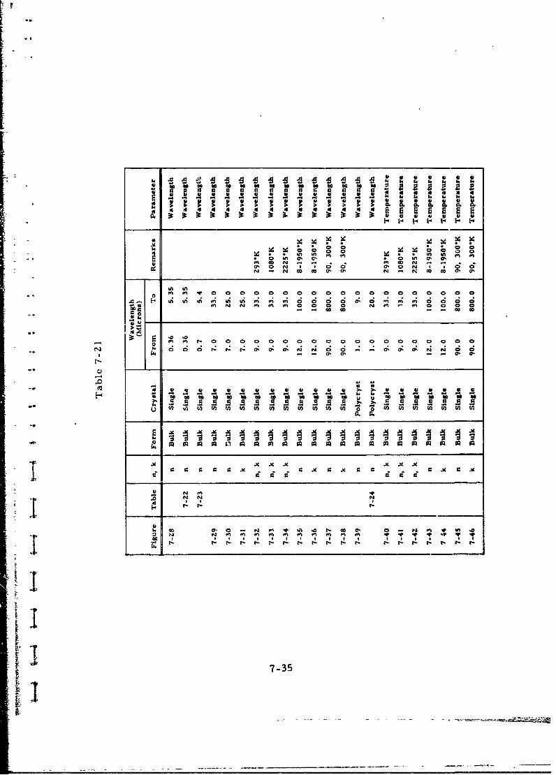
k4 3. 1 . 14 3
-1 N - - - - - - 8 4 3 4 3
ECI 47,C 0 N . a
m. 0 N% m m 0 0 O0 0 N% a In m m 0 am 0 0 . a N m Q' 0 . a
0
$4~~ ~ C-00 r - t- 0 Io 0 0 0-0 0 0 043, 5y
-~ ~~~~~~~ N E 1 -oooeoeaoc
-l a in4 U 3 U U U U 43 * 4 41 41 U 43 . ~ 41 ) 4 U Un
to - - - - - - 3 3
* U U U~, j U U 7-35U U

PARAMETER: .• velegnth MATERIAL: Magnesium Oxide
-7 iFORM Bulk, Single Crystal| ! 1.77 "
1.76 THICKNESS NA (Prism) mm
1.75RAY ORDINARY Ua, EXTRAORDINARY 0
1.74
: . €WAVELENGTH 0. 36 - 5. 35
Sim TEMPERATURE 296. 5 0
1.71
10 METHOD Deviation
1.69 REFERENCE Stephens and Malitson (34823)
REMARKS1.67
S~1.661.65 -
1.64
1.63 Figure 7-281.62 I I- -
0 0.4 I 2 3 4 50.75
WAVELENGTH, MICRONS
Wavelength, Index oi Refraction,(Microna) n
1.01398 1.72259
1.12866 1.72059
1.36728 1,71715
1. 5Z952 1.71496 Table 7-221.6932 1. 71281
1.7092 1.71258
1.81307 1.7110o
1.97009 1.70885
2.24929 1. 70470
2,3;542 1.70350
•.3033 1.-685263.5078 1.65C55
4.258 1.66C39
5, 138 1.63138
5.135 1.62404
7-36
11

PARAMETER: Wavelength MATERIAL: M agnesium Oxide
FORM Bulk, Single Crystal
Wavelength, THICKNESS not stated mm
(Microns) Refractive Index, nRAY ORDINARY B , EXTRAORDINAnY D
0. 6907 1. 73191 WAVELENGTH 0. 7 - 5.4
1.0140 1.7226TEMPERATURE -298 0K1. 9701 1. 70885
3.3033 1.68526 METHOD not stated
4.2580 1.66039 REFERENCE Norton (16227)
5.3500 1.62404• - _REMARKS Magnorite, Norton C;o.
Typical analysis: 99. 7 pe.rcent MgO,
0o 03 percent SiO?, 0. 04 percent CaO,
0.05 percent Fe 2 0 3 , 0.10 percent
Rz03 (other than Fe2 03).
Table 7-23
THICKNESS 0.0.- - 10 mm
12 RAY ORDINARY 0 , EXTRAORDNARY 3
"to WAVELENGTH 7 - 33 p
-- TEMPERATURE 298 OK
U METHOD Reflection
÷2 REFERENCE Haefele (34826)
300 500 700 900 Io0 1300 1500 REMARKS
I -"WAVE NUMBR, CM 1I
33 20 14 II 9.1 7.6 6.:S-: •WAVELENGTH, MICRONS
"- •.Figure 7-29
(I " d ii0 imbia
7-37

PARAMLTER: Wavelengt MATERIAL: Magnesium Oxide
FORM Bulk, Single Crystal
THICKNESS 0. 076 - G. 468 mm
x 2.0 RAY ORDINARY , EXTPAPDINAY 1
1 .2~1.6
WAVELENGTH 7 - 250.6 -
0.4 •
o0 ,, - TEMPERATURE -298 K
6 0 1o 12 14 26 16 20 ^2 24 26
WAVEIANG0H, MICRONS METHOD Reflcecti on
REFERENCE Wilrmott (34804)
REMARKS Samples CcleavedI from
massive crystal.
Figure 7-30
I
z 1-
10-2°' Figure 7-31
S10-4
6 8 10 12 14 16 11 20 22 24 26
WAVELANGTH, MICRONS
1; 7-38
- ,.. a

PARAMETER: Wav.Length MATERIAL:Magnesium Oxide
FORM Bulk, Single Crystal
_________THICKNESS not stated Im".20 I 15I , 293K RAY ORDINARY 0, EXTRAORDINARY
I ,'•5 I k"" '� \ 1: fWAVELENGTH 9 -33
-0 TEMPERATURE 293 2225I -, i • H
METHOD Reflection
300 500 700 900 1100
WAA. MEA•, cM"1 REFERENCE Piriou (29797)
33 20 149 REMARKS- 320 14 11 9.1
WAVELEN,4IH, MICRONS
Figure 7-?Z
Z 8 _- T 2225'K
Z 4
w300 50 700 900 1100 300 500 700 900 1100
33 20 14 11 9.1 33 20 14 II 9.1
WAVELENGTH, MICRONS WAVEIINGTH, MICRON,
Figure 7-33 Figure 7-34
CopyPIO-$6 8964 m#O:e t oie.
7-39
-1~~:•'"--*

U_
PARAMETER: Wavelength MATERIAL: Magnesium Oxide
FOR..M Bulk, Single Crystal
21 THICKNESS not stated mm
RAY ORDINARY U , EXTRAORDINARY C3
WAVELENGTH 12 - 100€
At
~0" k 4-TEMPERATURE 8 - 1950
,4 METHOD Reflection
REFERENCE Jasperse, et al. (3483Z)•" t0
REMARKS
19/0*1.2 6 CHANGE IN SCALE
000 43 -290% 1
3930K
SU 295"K
0.4~ 2 [.5 Figure 7-35
40 6w Soo0
4
WAVENULMR, CM1
SI i I !I IS100 5 33 20 2 14
WAVELENGTH, MICRONS
26-
20 -
12 - 545%K
9540 09K0
00 1
MXI~ONS 7-40

PARAMETER: Wavelength MATERIAL: Magnesium Oxide
FORM Bulk, Single Crystal
THICKNESS 0. 436, 0. 693 mm3.25
3.2 - RAY ORDINARY M , EXTRAORDINARY D
S"WAVELENGTH 90 - 800: "• 3.10- •3. HNIPPEL. 90
. 3.0oE TEMPERATURE 90, 300 0K
"3.00 METHOD Transmission
2.95 REFERENCE Rowntree (34819)10 15 20 25 30 40 50 60 708090 110
WAVE NUMEER, CM1 REMARKS
II I I I I i I 111i 1 -
-. 1000 667 500 400 333 250 200 167 143 125 100
WAVELENGTH, MICRONS
Figure 7-37
3 A10'2j1-
2
Fgr
1073
-I 3 x 100 0
AV10-3 • C
6 1_ -Figure 7 - 38
3 x1004 • -
S10 -4 ' , I
S15 20 25 30 40 50 60 70 90 I1(.
WV M , CM .I
IL I I I I j I I t I I 1
667 500 400 333 250 200 167143125111 92
i WAVELENGTH, MICRONS
177-41Il

PARAMETER: Wavelength MATERIAL: Magnesium Oxide
FORM Bulk, Polycrystalline
THICKNESS Not Stated mm
RAY ORDINA;4 W , EXTRAORDINARY 0)€ 1.S
x WAVELENGTH -.1.6 __ _ _ _ _ _ __ _ _ _ _ _
• 1.4 TEMPERATURE 298 0 K1.2 METHOD Not Stated
24 6 I
WAVP.iNGTH4, MIRONS REFERENCE Kodak [19671]
REMARKS IRTRAN-5 material
Figure 7-39
Wavelength, Refractive Wavelength, Refractl.(Microns) Index, r. (Microns) Index, n
1.0000 1. 7227 4.2500 1.6612
1.2500 1.7188 4.5000 1.6536
1. J000 .7156 4.7500 1.6455
1.7500 1.7123 5.0000 1.6368
2. 0000 1. 7089 5.2500 1.6275
2.2500 1.7052 5.5000 1.6177 Table 7-242.5000 1.7012 5.7500 1.6072
2. 7500 1.6968 6. 0000 1.5962
3. 0000 1.6920 6. 2500 1.5845
3.2500 1.6863 6.5000 1.5721
3.5000 1.6811 6.7500 1.5590
3.7500 1.6750 7.0000 1.5452
4. 0000 1.6684 7.2500 1.5307
7.7500 1.5154
7. 7500 1.4993
8. OOCO 1.4824
7-42

PARAMETER: Temperature MATERiAL: Magnesium Oxie
FORM Bulk, Single Crystal
THICKNESS Not Stated mm20-
'- T-293"K RAY ORDINARY , EXTRAORDINARY C31 5 --, WAVELENGTH 9 - 33
I ... nxK-o TEMPERATURE 293 - 2225 K"- 5
-- METHOD Reflection
300 500 700 900 1100
WAVE NUMBER,CM1 REFFRENCE Piriou (29797)
- I L i REMARKS33 20 14 II 9.1
WAVELENGTH, MICRONS
Figure 7-40
1v. 0 . 10
-8 O T - 2225'K
x -O
__v n -
-Z4 Z4
300 500 700 900 1100 0300 .Soo 700 900 1100
WAVE NUMBER, CM"1 WAVE NUMBER, CM"I
I _ - I I I I I I
33 14 II 9 1 33 20 14 1' 9.1
WAVELENGTH, MICRONS WAVELENGTH, MICRONS
Figure 7-41 Figure 7-4Z
' [hilhed with prINI.SS
Cepltoghte, 966 Msise oft Cie.
7-43

PARAMETER: Temperature MATERIAL: Magnesium Oxide
28
FORM Bulk, Single Crystal26M
26 8.S'K•
24 THICKNESS Not Stated mm
22 RAY ORDINARY U. EXTRAORDINARY
20WAVELENGTH 12 - 100
TEMPERATURE 8 - 1950 *KZ
14- METHOD Reflect. onU
1212-REFERENCE Jasperse, et al (34832)I,50-
950,K-.• REMARKS
8-
1.2 - 950-K CHANGE IN SCALE
/I1950*K4 /9 .K
8.[2 8.KFigure 7-43
200 400 600 Soo
WAVEletR. CM'"
I I I I I 1 I100 33 20 14
WAVELENGTH, MICRONS
30K
24
;.SK Figure 7-44
0 29SIK
z U 12 - 545*K.•.
910-.x. :I
6 WWI(K
4
2
0too 200 300 400 500 6w0
wAVI~uJ'MER, CM~
I8 I I4,"-, •I
100 50 33 25 20 17
WAVLEENGIH, NIOCRONS
7-44
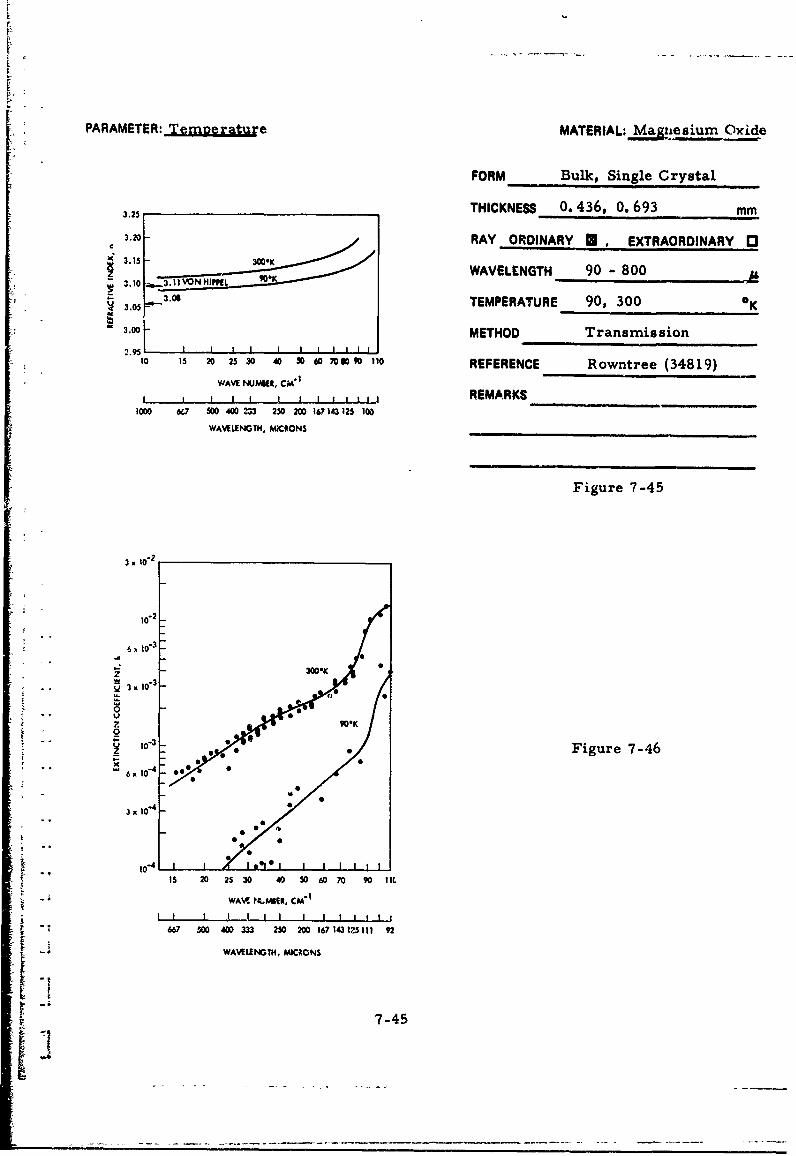
PARAMETER: Tepeature MATERIAL: M__agesium Owide
FORM Bulk, Single Crystal
THICKNESS 0. 436, 0. 693 mm3.25
3.20 - RAY ORDINARY U EXTRAORDINARY 1
3.15 300*K
.10 .WAVELENGTH 90 " 800
3.06 TEMPERATURE 90, 300 K3.0 METHOD Transmission
2.951 1 I I I I I I I I I10 15 20 25 30 40 50 6 708090 110 REFERENCE Rowntree (34819)
WAVE NUMUR, CA"
I I I I I I , I 1 1, REMARKS1000 6(7 500 400 = 250 200 167143 125 100
WAVELENGTH, MXCRONS
Figure 7-45
3 x 10"2
10`2
t!• IO3
. 3.10.
0
*1°'3 Figure 7-46• ' " '6. 1074
3. 10-4
S10-4- 1 1 1s l I I I I I I I
IS 20 25 30 40 50 60 70 90 I1.
WAV MMIER. CM"
S1 I I I I I I I I I I1 I I
667 500 400 3 250 200 167143125111 92
WAVELENGTH, MICRONS
[-,45

[F
CHAPTER 8
REFRACTIVE INDEX DATA FOR METALS
INTRODUCTION
This Chapter treats the optical properties of metal films
comprising the metals aluminum, gold and silver. The optical behav-
ior of metal films is dependent on film structure, and the latter is
influenced by the conditions under which the film was formed. Most of
the optical metal films were formed by evaporation in a vacuum of the
order of 10-5 torr and, at this pressure, the residual gas atoms are
sufficiently abundant to affect the film properties. Owing to the chem-
ical inertness of gold, films of this metal should not be influenced by
the presence of gases during evaporation to the same extent as alumi-
num and silver. In some cases a more volatile eutectic alloy may be
formed between the crucible (or boat) and the metal to be evaporated,
resulting in the deposition of an alloy rather than the pure metal. The
crystallinity of the film is dependent on the deposition rate and substrate
conditions, including type of material, orientation and temperature.
Annealing conditions frequently are not detailed sufficiently to ascer-
tain whether the film is amorphous or crystalline. The optical constants
of metal films show a dependence on film thickness and often the latter
either is not reported or not uniform. . should be apparent from the
foregoing discussion that agreement on optical constants of metal films
among various observers may be too much to hope for and, indeed, such
is the case.
The data permit some generalizations which apply to all threeF °metals. Extinction coefficients tend to show less spread among
observers; this is attributed by Schulz & Tangherlini (27635) to the
condition that k is dependent on the density of free electrons in the
metal, and this density is probably independent of structure defects.
The same authors explain the greater variation in the refractive index
(n) on its dependence on the conductivity of the metal, which is highlysensit;ve to the presence of defects and strains.
8-1
1.

DATA SUMMARY
Table 8-1 lists all data presentations for aluminum, gold and
silver. Figures 8-1 and Tables 8-2 to 8-8 provide aluminum data and
the lowering in refractive index by an amorphous-crystalline transforma-
tion is observed (Tables 8-2 versus 8-7); data -r the polycrystalline
film resemble bulk data and this is not unexpected as the density of poly-
crystalline film approaches that of bulk material, while amorphous alum-
inum has a much lower density [Motulevich, et al. (25734)].
Gold data are covered in Figures 8-2 to 8-6 and Tables 8 -9 to
8-20. Particularly interesting is Figure 8-3 which shows a reduction
in refractive index as a result of annealing. Table 8-11 shows the
great reduction which may occur in refractive index as the film thick-
ness approaches bulk levels. Similarly, an increase in extinction
coefficient is noted as the film thickness is increased (Table 8-12).
Data for silver are presented in Figures 8-7 to 8-14 and Tables 8-21
to 8-31. Refractive index and extinction coefficient values have been
calculated for a wide temperature range and are included as
Figures 8-13 and 8-14.
8-2

Table 8-1. List of Metal Data
K .Wavelength,(Microns)
Metal Figure Table n, k Form Crystal From To Remarks Parameter
Aluminum 8.2 n, k Film Amorphous 0.96 1.82 WavelengthAluminum 8-3 n, k Amorphous 2 12 Wavelength
Aluminum 8-1 n 0.4 0.95 Annealed film Wavelength
Aluminum 8-4 nh k 0. 4 0.95 Annealed film Wavelength(n)
Aluminum 8-5 n, k * 0.8 9.0 Wavelength
Aluminum 8-6 n * 0.4 2.0 WavelengthA Aluminum 8.7 n. k Polycryst 1.0 1.0 Wavelength* Aluminum 8-8 n, k * 0.8 9.0 Temperature
Gold 8-9 n Polycryst 1 12 Annealed film Wavelength
SGold 8-10 n, * 0.4 0.95 Annealed film Wavelength(n)
Gold 8-2 n 0.4 0.95 Annealed film Wavelength
Gold 8-11 n *0.8 1.1 WavelengthGold 8-12 k 0.8 2.0 Wavelength
Gold 8-3 n 0.4 2.5 Annealed and Wavelengthunannealed
t film
Gold 8-13 n. * 0.8 1.0 WavelunethGold 8-14 n, 0.8 1. 0 Wavelength
Gold 8-15 nh k 1.25 1.0 Wavelength
Gold 8.4 n 1.3 12.1 Wavelength
+ Gold 8-16 n 1.3 12.1 Wavelength
Gold 8-5 n 1 12 82*K, 295*K Wavelength
Gold 8-17 n *1 11 82-K. 295-K WavelengthGold 8-18 n 0.8 1.1 Film Thickness
-. Gold 8,19 k 0.a 2.0 Film Thickness
Gold 8-6 n 1 12 82K, 295"K Temperature
Gold 8-O n 1 11 82"K. 295"K TemperatureSilver 8-7 n 0.5 1.5 WavelengthSilver 8-21 n, k 0.8 1. 0 Wavelength
Silver 8-8 n *0.4 1.0 Wavelength
Silver 8-9 k 0.4 1.0 WavelengthSilver 8-10 n 0 0.95 Annealed film WavelengthSilver 8-22 n, k 0.4 0.95 Annealed film Wavelength
Silver 8-23 n, k 0.8 1.0 Wavelength
Silver 8-24 n. k 1.25 10 Wavelength
Silver 8-25 n 0 1.0 WavelengthSilver 8-26 k 0.8 1 1.5 Wavelength
Silver 8-1l * 1 12 82*K, 295%( WavelengthSilver 8-87 n 1 1i2 82"K, 295'K WavelengthSilver 8-12 nk n C. 3 00 300-1200"K Wavelength
Silver 8-28 n, k * 1. C 6.0 n-type Wavelength
Silver 8-29 n * 0.8 1.0 Film Thickness
"Silver 8-30 k * 0.8 1.5 Film Thickness
Silver 8-13 n * 1 12 82"K, 2951K TemperatureSilver 8-31 n 1 12 82"K, 295"K TemperatureSilver 8-14 nk * 0.3 100 300-1200K Temperature
Not stated.
8-3EN i

PARAMETER, Wavelength MATERIAL: Aluminum
FORM Film-AmorphousWavelength, Refractive Extinction(Microns) Index, n Coefficient, k THICKNESS Not stated mM
0.96 2. 0 10.2 RAY ORDINARY W , EXTRAORDINARY 0
1.15 1.8 12.0 WAVELENGTH 0.96-1.82 11.46 3.1 16.4
TEMPERATURE -298 OK
1.8Z 4.9 19.9METHOD Reflection
REFERENCE Mot'ilevich, et al. (25734)
REMARKS Film deposited on glass,
resulting in sample of mean density
of 2. 2 g cm"3
Table 8-2
Wavelength, Refractive Extinction THICKNESS . 5x10- 4 mm
(Microns) Index, n Coefficient, kRAY ORDINARY I , EXTRAORDINARY 3
2.0 2. 30 16. 5 WAVELENGTH 2 - 12 At
2.5 3.22 20.3 TEMPERATURE 298 OK3.0 4.41 24.2 ..
4. 0 5. 97 30.3 METHOD Reflection
5. 0 8. 19 36.8 REFERENCE Beattie [195536.0 11.00 42.4
REMARKS Specimens evaporated
7.0 14.63 49.0 -5
8.0 17.00 55. 0 onto glass substrate at ~ 10 tort
9.0 21.1 61.3 pressure.
10.0 25.4 67.3
11.0 28.3 71.1 TableB-3
12.0 33.6 76.4;w
8-5

PARAMETER: Wavelength MATEtiL: Alnuminum
FORM Film
THICKNESS 1.Sx10" 4 (n); 5x1 "{k) mm
RAY ORDINARY 0 EXTRAORDINARY [
C .0--WAVELENGTH 0.4 - 0.95 __
1.o TEMPERATURE ".298 °K0.8
0.6 METHOD Reflection (n); Interference (k).0.4 Schulz Tangherlin (27635)0.3- _ _ _ _ _ REFERENCE for n; Schulz (27634) for k.
0.4 0.5 0., 0.7 0.8 0.9 1.0WAVEIANGTH, MICRON$ REMARKS Evaporation from tungsten
wire at 10-5 Torr onto glass substrate
for n and mica substrate for k.
Figure 8-1
Wavelength, Refractive Extinction(Microns) Index, n Coefficient, k
0.40 0.40 3.92
0.45 0.49 4.32
0.50- 0.62 4.80
0.55 0.76 5.32
0.60 0.97 6.00
0.65 1.24 6.60 Table 8-4
- 0.70 1.55 7.00
0.75 1.80 i 7.12
0.80 1.99 7.05
0.85 2.08 7.15
0.90 1.96 7.70
0.95 1.75 8.50
8-6Ii

PARAMETER: Wavelength MATERIAL: Aluminum
Refractive Extinction FusM Film
Index, n Coefficient, kWavelength, THICKNESS 1. 5 X 10⁻⁵ m!
(Microns) 78°K 295°K 7 8°K 29 5°KRAY ORDINARY M , EXTRAORDINARY 0
0.8 0.83 1.12 6.0 6.0 WAVELENGTH 0.8 - 9.0S0.9 0.75 1.05 7A0 7.0
TEMPERATURE 78, 295 oK
1.2 10.63 0.95 9.6 9.61.5 METHOD Reflection
15 0.78 1.14 12.1 12. 1 __________
2. 0 1. 30 1.75 16. 1 16. 1 REFERENCE Golovashkin, et al. (14298)S2. 5 1.7 2.4 19.8 09.8257 .18 .REMARKS Film formed by vacuum
4 3.0 2.2 3.2 23.5 23.5S4. 0 3. 2 4. 8 30. 1 30. 0 evaporation from tungsten helix onto
51 0 4.4 6.7 37.8 37.6 glass.
6.0 6.5 9.5 44.9 44.4 Table 8-5
12.6 52.0 49.0
8.0 15.6 55.0
9.0 21.1 61.3
Wavele,,gtk;, Refractive THICKNESS. Not Stated mm(Mi~croi),s) Index, _ _n___
_(__ cro______dex, RAY ORDINARY • , EXTRAORDINARY C0
0 A' 0.32 WAVELENGTH 0.40 - 2.00
0.70 1.26
0.75 1,50 TEMPERATURLt 298 OK
0.80 1.78 METHOD Reflection0.85 1. 9 iShlkyarevskii and.0.875 1.8 REFERENCE Yarovaya (1998.J
0. 90 1. 70 REMARKS Evaporation at 2xl0"5 torr
0.95 1.40 onto glass substrate
1.00 1.17
1.10 0.85 Table 8-61.20 0.78
1.50 1.00• • .•!1.70 1. 31
2. 00 1. 74
"I 8-
]it 8-7

PARAMETER: _Wavelength MATERIAL: Aluminum
TFORM Film - Polycrystalline
Wavelength, Refractive Extinction(Microns) Index, i. Coefficient, k THICKNESS Not Stated mm
1.00RAY ORDINARY EXTRAORDINARY 03
1.50 1.14 11.6 WAVELENGTH 1 - 10
2. 00 1.67 15. 2 TEMPERATURE -298 OK
2.50 2.50 18.8METHOD Reflection3.0O0 3.48 22. 6
4. 00 5. 58 29.4 REFERENCE Motulevich, et al. (Z5734)
5. 00 7.84 35.7 REMARKS Film deposited on glass,
6.00 10.4 41.3
8. 00 16. 2 52. 2 resulting in sample density of
10,0 25.5 60.9 2. 7 g cm-3 .
Table 8-7
8-8
I - --------.-[

PAMT .Tunierature AuiuPARAMETER.: MATERIAL: Aluminum
__- FORM FilmRefractive Extinction THCNSS 1 1 5MIndex, n Coefficient, k TIKES . 05m
Wavelength,,Waicrons 780K 295°K 780K 295°K RAY ORDINARY U, EXTRAORDINARY 03
0.8 0.83 1. 12 6.0 6.0 WAVELENGTH 0.8 - 9.0
0.9 0.75 1.05 7.0 7.0 TEMPERATURE 78, 295 0K
1.2 0.63 0.95 9.6 9.6
1.5 0.78 0.14 12. 1 12.1 METHOD Reflection
2.0 1.30 1.75 16. 1 16. 1 REFERENCE Golovashkin, et al. (14Z98)
2. 5 1.7 2.4 19.8 19.8 REMARKS Film formed by vacuum
3.0 2, 2 3.2 2.;. 5 23.5
4.0 3. 2 4.8 30. 1 30.0 evaporation from tungsten helix onto
5.0 4.4 6.7 37.8 37.6 glass.
6.0 6.5 9.5 44.9 44.4 Table 8-8
7.0 1z. 6 52.0 49.0
8.0 15.6 55.0
9.0 21.1 61.3
8-9

PARAMETER: .... 1Cn,-,,, MATERIAL: Gold
FORM Film - Polycry3talline
Wavelength, Refractive Extinction THICKNESS (0. 5 - 1) x 10" 3 mmMicrons Index, n Coefficient, k
1.0 0.224 6.71 RAY ORDINARY E: , EXTRAORDINARY .0
1.5 0.357 10.4 WAVELENGTH 1 - 12
2. 0 0. 546 13.9 TEMPERATURE -298 0 K
2. 5 0.82 17.3 METHOD Reflection
3.0 1.17 21.0REFERENCE Motulevich & Shubin (1992Z)
4.0 2.04 27.9
5.0 3.27 35. 2 REMARKS Evaporation at 3 x 10"6 torr
6.0 4.70 41.7 pressure from tungsten onto glass
8.0 7.82 54.6 substrate, followed by anneal of at
10.0 11.5 67.5 least three hours at 10- 6 torr and
12.0 15.4 80.5 673 0 K.Table 8-9
PRECEDING PAGE BLANK
8-11

PARAMETER: Wavelength MATERjAL: Gold
FORM FilmWavelength, Refractive Extinction(Mirons) Index, n Coefficient, k THICKNESS .5) m
0.40 1.4: RAY ODINARY ,EXTRAORDINARY I1
0.45 1. 40 1.88WAVELENGTH 0.4 - 0.95 At
0.50 0.84 1.84
0. 55 0.34 2 37 TEMPERATURE -%98 °K
0.60 0. 23 2.97 METHOD Reflection (n); Interference (k).
0.65 0.19 3.50 Schulz & Tangherline(Z7635)REFERENCE for n, Schulz (27634) for k.
0.70 0.17 3.97
0.75 0.16 4.42 REMARKS Evaporation from tungsten
0.80 0.16 4.84 wire at 10 5torr onto glass substrate
0.85 0.17 5. 30 for n and mica substrate for k. Glass
0. 90 0. 18 5.z ~substrate sample annealed at <403' K
0.95 0.19 6.10 Table 8-10
2.0
1.0 !C 0.8
g0.60.40. Figure 8-2
S0.3-
S0.2 -"
0.110.4 0.5 0.6 0.7 0.8 0.9 1.0
WAV•LEINGTH, MICRONS
8-12

L\
PARAMETER: Wavele. •}h MAT ERiA; .. l.
___ _ _FORM FilmRefractive Index. n
I Film Th .lkess. @ Wavelength Microns 60 0.8 0.9 1.0 1.1 Observer THICKNESS 1 x 10 to bulk mm
to 4.35 4.5 4.85 5.05 Coos 11937] RAY ORDINARY EXTRAORDINARY 020 5.25 5.1 5.0 5.0 Coos [1937]
30 5.05 5.15 5.0 5.0 Coos11937) WAVELENGTH 0.8 - 1.1
40 4.15 4.7 4.9 5.15 Coos (1937)
so 4. 3 4.55 4.9 5.15 Coos[1937] TEMPERATURE -298 K
75 4.3 4.6 4.75 5.15 Coos 119371
100 3.5 3.95 4.35 4.85 Goos ,19371 METHOD Miscellaneous
Iso 1.4 1.8 2.15 2.55* Coos [1937] MET1OD200 0.45 0.5 0.55 0.6 Coo:11937] REFERENCE Mayer [1950]
400 0.18 0.19 0. 195 Kretzmann (40353)
,0.2 REMARKS Compilation of older
*Thicknets range 100-400 data
Table 8-11
. . Extinction Coefficient, ItFilm Th ckness, @ Wavelen th Microns
i 0.8 0.9 1.0 1. 11 1.5 2. 0 Observer
10 0.7 0.5 0.25 0.05 Coos [1937]
20 1.65 1.1 0.7 0.35 Goos* 1937)
30 2.75 1.75 1.25 0.8 Coot [19371
40 2.9 2.3 1.95 1.3 Goos [1937]
50 3.3 Z. 8 2.6 2.0 Coos [1937]
75 4.1 3.7S 3.6 5.3 Coos [1937] Table 8-12
100 4.55 4.5 4.4 4.4 Gooe [1937]
5.56' Haringhozcn. at &1. [1937]
150 5.0 5.45 5.8 6 4 Goo@[ 1937]
200 5.Z 5.9 6.7 7.5 Coos [1937]
500.1000 S.19 6.9 11.3 15.4 Hagen & Rubens@ 1902]
5.2 6.0 6.9S 7.65 Goos [1937]
4.2 4.93 5.57 Statescu 1910]
1Thickness range 100-400JA
8-13

PARAMETER: Wavelength MATERIAL: Gold
FORM Film
THICKNESS Not stated mm
__________________RAY ORDINARY .,EXTRAORDINARY0
WAVELENGTH 0.4 - 2.5
0 0.5 1.0 1.5 ý.0 2.5 TEMPERATURE -298 oK
WAVEUENGTH, MICRONS
I 1 SAMPLE NO. I EFORE ANNEALING METHOD Reflectiona 2 SAMPLE NO.I AFTER ANNEALING3sA NO.2 KFOE ANNEALING Shklyarevskii & Yarovaya
8 4 SAMPLE NO.2 AFTERAANNEALING REFERENCE (27261)6 5 MOTULEVICH AND SHUMIN, REF 19922t 6 PADALKA AND SHKLYAREVSKII, REF 9953o 7 OTTER, 11911 REMARKS Deposition rates: Sample
No. 1- oneA sec"1, sample No. 2-
100 A sec. Samples annealed at393°Kin vacuo after deposition, where
stated.
Figure 8-3
THICKNE3S 0.33 mmWavelength, Refractive Extinction(Microns) Index, n Coefficient, k RAY ORDINARY , EXTRAORDINARY 0
0.800 0.178 4.20 WAVELENGTH 0.80 - 1.0
TEMPERATURE -298 OK0. 850 0.182 4.53
METHOD Reflection0. 900 0. 190 4.93
0.950 0.199 5.27 REFERENCE Kretzmann (40353)
1.000 0.194 5.57 REMARKS Evaporation from tungstzn
or molybdenum crucibles at
<1 x 10 torr.
Table 8-13
8-14

PARAMETER: Wavelength MATIRiAL: G;Ad
FORM FilmWavelength, Refractive Extinction(Microns) Index, n Coefficient, k THICKNESS 0.3 - 0.4 mm
0. 800 0. 149 4. 654 RAY ORDINARY -, EXTRAORDINARY 0
0. 850 0.157 4.993 WAVELENGTH 0.8 - 1.0 ii
0. 900 0. 166 5. 335 TEMPERATURE -298
0. 950 0. 174 5.691 METHOD Reflection
i.000 0. 179 6.044 REFERENCE Weiss (6107)
REMARKS Evaporation onto silica
substrate at. 2 x 10- torr pressure
"Table 8-14
Wavelength, Refractive Extinction(Microns) Index, n Coefficient, k
THICKNESS Not stated mm
12,5 0.38 8.0 RAY ORDINARY U, EXTRAORDINARY [3
1.5 0.53 9.5 WAVELENGTH 1.25 10
2 0.85 12.6 TEMPERATURE 293 OK
3 1.64 18.6 METHOD Reflection
4 2.6 24.6 REFERENCE Dold & Mecke (27079)
5 3.8 30.7 REMARKS Evaporation from
6 5.1 36.4 tantalum crucible.
7 6.8 41.6
8 8.5 46.4 Table 8-15
9 10,5 50.8
10 12.4 55.0
8-15
1

q
j7'
PARAMETER: Wavelength MATERIAL: Gold
IFORM Film33 3
THICKNESS (1. 5 2) x 10- mm
RAY ORDINARY * EXTRAORDINARY D330 -
WAVELENGTH Is 12
TEMPERATURE -298 K20 METHOD Reflection
Shkliarevskii &REFERENCE Padalka (36056)
is-REMARKS Vacuum evaporation from
10- molybdenum crucible onto glass sub-
strate. According to the authors,
samples may have been insufficiently
""LI I I clean, resulting in high refractive
2 4 6 8 10 12 ihdices."WAVELENGTH, MICRONS
Figure 8-4
Wavelength Refractive(Microns) Index, n
1.3 0.69
1.75 1. 1
1.95 1.3
2.26 1.62
2.8 2.2
"!3.43 3.49
3947Table 8-16i '* **3.95 4.71
4.55 5.95
I 5.5 9.05'i6.65 12.9
7.9 17.6
8.65 20.2
~ 1 9.9 25.2
11. 1 29.0
12.1 3Z. 4
I8

[:1
PARAMETER: Wavelength MATERIAL: Gold
FORM Film
THICKNESS Not stated mm
RAY ORDINARY U . EXTRAORDINARY "
WAVELENGTH 1 - 13 _
TEMPERATURE 8Z, 295 0KC
" S METHOD ReflectionPadalka
REFERENCE Shklyarevskii (9953)-M
REMARKS Evaporation from tantalum
crucible onto glass substrate at
-10"5 torr pressure.
2 •Figure 8-5
II J : I I, ,
0 2 4 6 9 10
WAVELNGTH, MICRONS
Wavelength, Refractive Index, n
(Microns) T = 295°K T = 82°K
n n
"Table 8-171 0.31 0.28
2 0.54 0.45
3 0.93 0.74
4 1.49 1.15
5 2.19 1.67
6 3.01 2.29
7 3.97 2.99
8 5.05 3.84
9 6.21 4.74
10 7.41 5.70
"11 8.71 6.76
8-17
-!

-' t -
Ii•[ PARAMETER: Temneratue MATERIAL: Gold
FORM Film
THICKNESS Not stated mm
RAY ORDINARY ] , EXTRAORDINARY l -.
10 WAVELENGTH 1 - 12 1 "
TEMPERATURE 82, -95 0K
METHOD ReflectionPadalka &r
REFERENCE Shklyarevskii (9953)
9- S.K, REMARKS Evaporation from tantalum
icrucible onto glass substrate at .
10-5 torr pressure.820K Figure 8-6
2
0 2 4 6 8 10
WAVELENGTH, MICRONS
8-18

PARAMETER: Fi•.m Thickne, 5 MAT--R!AL: Go3 I
FORM FilmRefractive Pidex, a
Film rh0ckne. -0 0.9 1t. oM.r°.1 Ob.erver THICKNESS 1 x 10- 6 to bulk . jlL
10 '4.3[4.5 4.15 5.05 G,1 C 9371 RAY ORDINARY X, EXTRr.O;,DINARY C3z0 S. 25 5.1 5.0 5.0 Coos (1937]
30 5.o5 5.:5 5.0 5.o os [19371 WAVELENGTH 0.8 - 1.140 4.315 4.7 4.9 5.15 Coos [1937]
50 4. 1 4. 55 4.9 S. s Coos [19371 TEMPERATURE -2987S 4.3 4.6 4.75 5.15 Coos [1937] METHOD Miscellaneous
300 3. 5 3.95 4.35 4.85 Coos11937]1,Io 1.4 3.8 2. 15 2. 55* Coo, [1,0371 REFERENCE Mayer [1950]
! "" 00 0.41 IL 1 0,55 0.6 Go.. 1193717400 0.45 0.5 0.55 0.6 Coos ( 403 S3 REMARKS Com pilation of older data••400 0. 38 0.319 0. 195 Kret,.mann (40353)
0.2 0125 0.25 0.3 Poany [(1916]
'Thickness range 060-400 A
Table 8-18
S--1. • .i ' ,
i7'. IT ' I "' .... .i
-. 4u 1 Z.( I ' 3 C.m- I)171
-- I0, 4. SS 4.S 4.4 4.4 I•...I"?
5, ',* * I Il ni 'en. et .1. [171 T able 8- 1o9I-S 4) S 4 . ,
5I .... .... 7 7.5 ( " 71
S . A
8-19

10
YL
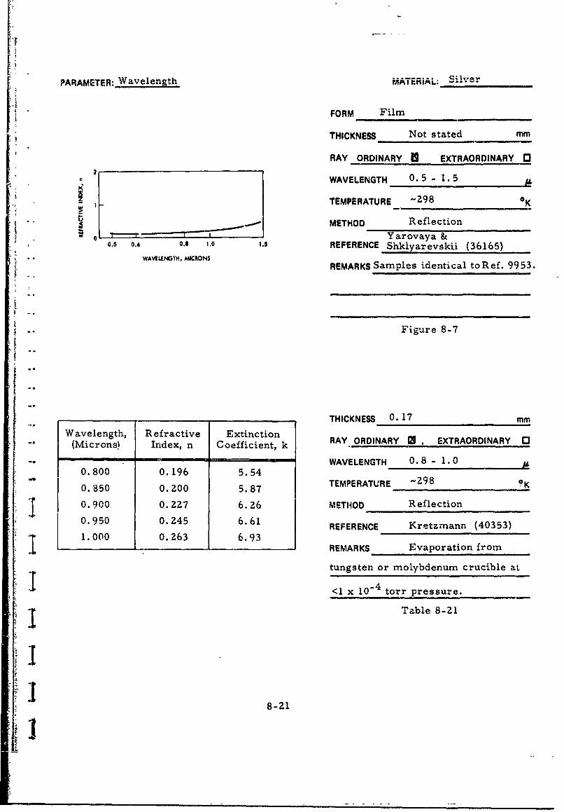
PARAMETER: Wavelength MATERiAL; Silver
FORM Film
THICKNESS Not stated mm
RAY ORDINARY 1 EXTRAORDINARY I"
WAVELENGTH 0.5 - 1.5
TEMPERATURE -298 •K
S . METHOD Reflection
1 -- Yarovaya &0.5 0.6 0.8 ,.0 ,.5 REFERENCE Shklyarevskii (36165)
WAVIUNYM, MCRONSREMARKS Samples identical to R ef. 99 53.
Figure 8-7
THICKNESS 0.17 mrm
Wavelength, Refractive Extinction RAY ORDINARY EXTRAORDINARY ["(M i c r o n s ) I n d e x , n C o e f f i c i e n t , k WA V E L EN A R Y - 1 At
-- "~ WAVELENGTH 0.8 - 1.0 /
0.800 0.196 5.54
0.350 0.200 5.87 TEMPERATURE -298
f 0.900 0.227 6.26 METHOD Reflection
0.950 0.245 6.61 REFERENCE Kretzmann (40353)1 . 000 0.2Z63 6.931.000 0.263 6 REMARKS Evaporation from
tungsten or molybdenum crucible at
<1 x 10"4 torr pressure.
I Table 8-21
I8S~8-21
K'

PARAMETER: Wavelength MATERIAL: Silver
FORM Film-4
THICKNESS >0.7 x 1i0 mm
RAY ORDINARY 1 . EXTRAORDINARY 0c 0.3-
0. - WAVELENGTH 0.4 - 1.0 ..
_ .2 TEMPERATURE -298 0 K
o0.1 I METHOD Reflection, Transn.ission
0.05 __ _ _ _ _ _ _ _ _ _ _
, , , , , , REFERENCE Idczak [196710.4000 0.50 0.6000 o to 0.700 0 0.9o0,o 1.000
WAVLENTH, MICRONS REMARKS Film prepared by
evaporatidn onto glass substrate
at -10"4 torr.
Figure 8-8
6 6z
U - Figure 8-9
I I ! I i i I I I I I
0.4000 0.5000 0.6000 0.7000 0.8000 0.9000 1.000WAVULENGTH, MICRONS
8-22
i• ,

PARAMETER- Wavelength MATERIAL: Silver
FORM Film
THICKNESS 1.5x1064 for n,5xl0"5 for k mm
RAY ORDINARY 3, EXTRAORDINARY 0
0.20 WAVELENGTH 0.4 - 0.95
1.10 TEMPERATURE -298 0K
_0.06 METHOD Reflection (n); Interference (k)" "� •• Schulz & Tangherlini (T7635)
.041 I I REFERENCE for n, Schulz (27634) for k." '0.4 0.5 0.6 0.7 0.8 0.9 1.0
. WAVELENGTH, MhCRONS REMARKS Evaporation from molybde-
num crucible at -10- torr onto glass
"substrate for n, mica substrate for k.
Figure 8-10
"" Wavelength, Refractive ExtinctionL.(Microns) Index, n Coefficient, k
0.40 0.075 1.93
0.45 0.055 2.42
0.50 0.050 2.87
0.55 0.055 3.32
0.60 0.060 3.75
0.65 0.070 4.20 Table 8
I 0.70 0.075 4.62
0.75 0.080 5.05
0.80 0.090 5.45
-. Io0.85 0.100 5.85
0.90 0.105 6.22
0.95 0.110 6.56
8-23
I

PARAMETER: Wavelength MATERIAL: Silver
Wavelength, Refractive Extinction FORM Film(Microns) Index, n Coefficient, k
THICKNESS M.1M - 0.2 mr0.800 0.110 5.409
0.850 0.II 5.757 RAY ORDINARY 1 , EXTRAORDINARY "1
0.900 0. IZ8 6.089 WAVELENGTH 0.8 - 1.00
0.050 0.130 6.476 TEMPERATURE -298 0K
1.000 0.129 6.829
METHOD Reflection
REFERENCE Weiss (6107)
REMARKS Evaporation from tungsten
or molybdenum crucible onto silica
substrate at 2 x 10- torr.
Table 8-Z3
THICKNESS Not stated mmWavelength, Refractive Extinction
(Microns) Index, n Coefficient, k RAY ORDINARY 0 , EXTRAORDINARY 0
1.25 0.37 7.7 WAVELENGTH 1.25 - 10
1.5 0.45 9.0
2 0.65 12.2 TEMPERATURE Z93 oK
3 1.30 18.2 METHOD Reflection
4 Z.3 24.3REFERENCE Dold & Mecke (27079)
5 3.5 30.4
6 5.0 36.0 REMARKS Evaporation from
7 6.9 41.0 molybdenum crucible.
8 8.9 46.0
9 11.0 50.0Table 8-24
10 13.3 54.0
8-24
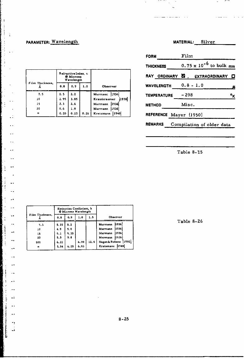
PARAMETER: Wavelength MATERIAL: Silver
FORM Film
THICKNESS 0. 75 x 106 to bulk mm
Refractive Index, .@ Microns RAY ORDINARY , EXTRAORDINARY "1Wavelength
Film Thickness,A 0.8 0.9 1.0 Observer WAVELENGTH 0.8 - 1.0
7.5 Z. 5 2. z Murmanr 1J9361 TEMPERATURE - 298 K1 0 2.95 3.05 Krautkraemer 119381is 2.3 2.6 Murmann 119361 METHOD Misc.20 0.6 1.0 Murmann 119361
0.20 0.23 0.26 Kretzmann 119401 REFERENCE Mayer [1950]
REMARKS Compilation of older data
Table 8-15
"Extinction Coeficient, k@ Microns Wavelength
Film Thickness, -A 0.8 0.9 1.0 1.5 Observer
j Murmann 119361 Table 8-26
4.9 5.0 Murmann 119361isO 5.1 5.3S Murmann 11936120 5.5 '.!Murmann 119361
" Soo b. 00 12.4 Hagen&Rubens 11902105.54 6.5 6.93 Kretsmann 119401
8-25

PARAMETER: Waveiength MATERIAL: Silver
14FORM Film
12 THICKNESS Not stated mm
RAY ORDINARY * , EXTRAORDINARY 3
1 WAVELENGTH 1 - 1A
TEMPERATURE 8Z, 295 0 KC
METHOD ReflectionPadalka &
6 .*K 82K REFERENCE Shklyarevskii (9953)
REMARKS Evaporation from
tantalum crucible onto glass4
substrate at 10-5 torr
2 Figure 8-11
0 I I I0 2 4 6 8 10 12
WAVELENGTH, MICRONS
Refractive Index, nWavelength,.
(Microns) T = 295 0 K T = 82'K
1 0.25 0.22
2 0.68 0.57 Table 8-27
3 1.38 1.14
4 2.34 1.925 3.5Z 2.886 4.87 4.027 6.31 5.31
8 7.86 6.709 9.36 8.10
10 10.8 9.60
11 12.0 10.9
12 12.8 --
8-26

PARAMETER: Waveiength MATERIAL: Silver
,o10 FORM Not stated=DATA FROM :"GREEN, E L, OPTICAL PROPERTIES OF THE ,
G OALPHA PHASE ALLOYS, ApZn ANDA ACd. -p 300K THICKNESS Not stated mmREPORT JUUA•IhR AD 6181 (196). 600 K
900 K
1l00. 1200KSRAY ORDINARY 0: EXTRAORDINARY 3
2 D•O WAVELENGTH 0.3 - 100
10 "n TEMPERATURE 300 - lZ00 0K
" METHOD NA- ~ I,
//REFERENCE Grenis (30490)
k WAIVED FROMEXPERIMENTAL REMARKS Calculated results, basedDATA, TEMPERATURE 295 K)
0.1 on optical, conductivity and--- - CALCULATED" " • CALCULATED
-- ESTIMATED dielectric measurements.
0.01 - , iiiii, , 1 , 1. 1 1 11[[ Figure 8-1Z- " 0.1 1 10 100
WAVELENGTH, MiCRONS
"Wavelength, Refractive Extinction THICKNESS Not stated-Mirror mm(Microns) Index, n Coefficient, k
RAY ORDINARY U , EXTRAORDINARY 031.03 0.27 7.00 WAVELENGTH 1 - 61.Z8 0.36 8.58
"1.71 0.53 11.7 TEMPERATURE -298 OK
Z.50 0.91 17.Z METHOD Reflection
3.48 1.65 23.75 REFERENCE Motulevich (40051)
4.38 Z.0 29.65
5.38 2.9 36.9 REMARKS n-t ie, carrier concentration
6.00 4.3 40.65 5.2x 102 cm"3
"r Table 8-Z8
Ii8-Z
i 8-27

A; LLL l. UL,,.Z%,&I, b
PARAMETER: MATERIAL: Silver
FORM Film
THICKNESS 0. 75 x 10"6 to bulk mmRefractive Index, n@ MicronsWavelensth RAY ORDINARY fl, EXTRAORDINARY (3
Film Thickness,0.8 0.9 1.0 Observer WAVELENGTH 0.8 - 1.0
7.5 2.5 Z. z Murmann 119361t0 2.95 3.05 Krautkraemer 119381 TEMPERATURE Kis 2.3 2.6 Murmann 119361zo 0.6 1.0 Murmann 119361 METHOD Misc.
0.20 0.23 0.A6 Kretzmann 119401 REFERENCE Mayer [19501
REMARKS Conipilation of older
data
Table 8-29
Extinction Coefficient, k@ Microns Wavelength
Film Thfrkness. - - - - S0.8 0.9 1.0 1.5 Observer
7.5 5.15 5.2 Murmann 119361 Table 8-3010 4.9 5.0 Murmann 11936115 5.1 5.3S Murmann 119361
20 5.5 5.8 Murmann 119361
o00 6.21 8.00 12.4 Hagen&Rubens 1190215.54 6.25 6.93 Kretzmann 119401
---
!iiii
t -___

L
PARAMETER: Temperature MATERIAL: Silver
'4F FORM Film
12 - THICKNESS Not stated mm
RAY ORDINARY L, EXTRAORDINARY "1
10 o WAVELENGTH 1 12
TEMPERATURE 82, 295 0K
METHOD Reflection- ~(995'3)
S2.K REFERENCE Padalka & Shklvarevskii"REMARKS Evaporation from tantalum
crucible onto glass substrate at4
"10 torr
2k__ " Figure 8-13
• • . I I I
0 2 4 6 8 10 12
WAVELENGTH, MICRONS
Refractive Index, nWavelength,
Micron T 295 0 K T 82°K
1 0.25 0.222 0. 68 0. 573 1.38 1.14
4 2.34 1.92
5 3.52 2.88 Table 8-31
6 4.87 4.027 6.31 5.31
8 7.86 6.70
I *9 9.36 8.10
10 10.8 9.60
11 12.0 10.0
12 12.8 --
8-29

LiI
PARAMETER: Temperature MATERIAL: Silver
t FORM Not Stated mm
"DATA FROM:
GREEN,[E I., OPTICAL PROI'ERTIES OF THE -m-ALPHA PHASE ALLOYS, A!ZnANDAqCd. -300K THICKNESS Not Stated mm-REPORT NUMAR AD 619301 (1965). /, •600 K
w ~ 900 K100 120K 200 K RAY ORDINARY C2, EXTRAORDINARY 03
",/' WAVELENGTH 0.3 - 1002600 K/
• 300!o K 0\,,•¢11t 300 TEMPERATURE 300 - 1200 K
2METHOD NA
REFERENCE Grenis (30490)
"-k FREMARKS Calculated results, based-k(D•RIV!D FROM EXPERIME•NTAL
DATA, TEMPERATURE 295 K)
0.1 on optical, conductivity and dielectric- --- CALCULATED
CALCULATED measurements.- ------ ESTIMATED
0.01 llil I iiil i I lii i Figure 8-140.1 1 10 100
WAVELENGTH, MICRONS
18-30
ill
II
I ________________

CHAPTER 9
BIBLIOGRAPHY
EPIC-INDEXED REFERENCES
ARONSON, J. R., et al., (16091) Low-Temperature Far-InfraredSpectra of Germanium and Silicon. PHYS. REV., v. 135, no. 3A,"Aug. 3, 1964. p. A785-A788.
BALKANSKI, M. and J. M. BESSON, (22653). ECOLE NORMALESUPERIEURE. FRANCE. Optical Properties of Degenerate Silicon.TN no. 2. Contract no. AF 61-052-789. 1965. DDC AD-619 581.
BALLARD, S.S, (12539). MICHIGAN UNIV. WILLOW RUN LAB.Optical Materials for Infrared Instrumentation. State- of-the -Art4 K Rept., Rept. no. 2389-11-S, Jan. 1959. Contract no. Nonr 1224-12.ASTIA AD-217 367.
BIENIEWSKI, T.M. and S.J. CZYZAK, (8761). Refractive Indexesof Signal Hexagonal Zinc Sulfide and Cadmium Sulfide Crystals.OPTICAL SOC. OF AMERICA, J., v. 53, no. 4, Apr. 1963.p. 496-497.
BERMAN, L.V. and A.G. ZHUKOV, (36032). Optical Constants ofCrystalline Quartz in the Far Infrared Region. OPT. AND SPECTRO.,v. 21, no. 6, Dec. 1965. p. 401-404.
BRIXNER, B., (29206). Refractive-Index Interpolation for FusedSilica. OPTICAL SOC. OF AMERICA, J., v. 57, no. 5, May 1967.p. 674-676.
BURGIEL, J.C. et al., (34617). Refractive Indices of Zinc Oxide,Zinc Sulfide, and Several Thin-Film insulators. ELECTROCHEM.SOC., J., v. 115, no. 7, July 1968. p. 729-732.
CARDONA, M. et al., (620). Dielectric Constant of Germanium andSilicon as a Function of Volume. PHYS. AND CHEM. OF SOLIDS,v. 8, Jan. 1959. p. 204-206.
CARDONA, M., (2569). HARVARD UNIV., GORDON McKAY LAB.OF APPL. SCI. Dielectric Constant of Germaniium and Silicon as a
' Function of Volume. TR no. HP-5. Contract Nonr-186610.July 1, 1959. AD 226 982.
CHAMBERLAIN, J.E. and H.A. GEBBIE, (40177). Determinationof the Refractive Index of a Solid Using a Far Infra-Red Maser.NATURE, v. 206, no. 4984, May 8, 1965. p. 602-603.
CHAMBERLAIN, J. E., et al., (40179). Refractometry in the FarInfra-Red Using a Two-Beam Interferometer. NATURE, v. 198,no. 4883, June 1, 1963. p. 874-875.
CLEEK, G.W., (27331). The Optical Constants of Some OxideGlasses in the Strong Absorption Region. APPLIED OPTICS, v. 5,no. 5, May 1966. p. 771-776.
9-I2

COLLINS, R.J., (40273). PURDUE UNIVERSITY. Infrared Propertiesof Germanium. Doctoral Thesis, Aug. 1953. p. 76-79-.
BLOCK, W., et al, (36747). Material Measurement Schemes for theFar Infrared. APPLIED OPTICS, v. 7, no. 11, Nov. 1968.p. 2319-2320.
BOGENS, R.K. and A.G. ZHUKOV, (35268). The Optical Constantsof Fused Quartz in the Far Infrared. J. OF APPLIED SPECTROSCOPY,v. .4, no. 1, Jan. 1966. p. 54-55.
BOND, W. L., (19989). Measurement of the Refractive Indices ofSeveral Crystals. J. OF APPLIED PHYS., v. 36, no. 5, May 1965.p. 1674-1677.
BOSOMWORTH, D.R., (29681). Far-Infrared Optical Properties ofCalcium Fluoride, Strontium Fluoride Barium Fluoride, and CadmiumFluoride. PHYS. REV., v. 157, no. 3, May 15, 1967. p. 709-715.
BRATTAIN, W. H. and H. B. BRIGGS, (18391). The Optical Constantsof Germanium in the infra-Red and Visible. PHYS. REV., v. 75,no. 11, June 1, 1949. p. 1705-1710.
BRIGGS, H.B., (13314). Optical Effects in Bulk Silicon and Ger-manium. PHYS. REV., v. 77, no. 2, Jan. 15, 1950. p. 287.
COX, J.T., et. al., (17066). Improved Dielectric Films for Multi-layer Coatings and Mirror Protection. J. DE PHYS., v. 25, no. 1-2,Jan.-Feb. 1964. p. 250-254.
CZYZAK, S.J., et. al., (6331). Refractive Indexes of Single Syn-thetic Zinc Sulfide and Cadmium Sulfide Crystals. OPTICAL SOC. OFAMERICA, J., v. 47, no. 3, Mar. 1957. p. 240-243.
CZYZAK, S.J., et al., (14914). DETROIT UNIV. The Study ofProperties of Single Cadmium Sulfide and Zinc Sulfide Crystals for useas Detectors in Crystal Counters. TR no. 3. Contract no. Nonr 1511-01-NR-015-218. Oct. 1957. ASTIAAD-143 919.
DAVEY, J.E., et al., (13363). The Effect of Vacuum-EvaporationParameters on the Structural, Electrical and Optical Properties ofThin Germanium Films. SOLID STATE ELECTRONICS, v. 6, no. 3,May-June 1964. p. 205-216.
DAVIS, P.W. and T.S. SHILLIDAY, (3648). Some Optical Propertiesof Cadmium Telluride. PHYS. REV., v. 118, no. 4, May 15, 1960.p. 1020-1022.
DE NOBEL, D., (306). Phase Equilibria and Semiconducting Prop-erties of Cadmium Teth.ride. PHILIPS RES. REP., v. 14, no. 4,Aug. 1959. p. 361-399.
9-Z

DEVORE, J.R., (40276). Refractive Indices of Rutile and Sphalerite.OPTICAL SOC. OF AMERICA, J., v. 41, no. 6, June 1951.p. 416-419.
DIANOV, E.M. and N.A. IRISOVA, (41423). Determination of theAbsorption Coefficient of Solids in the Short-Wave Region of theMillimeter Band. J. OF APPLIED PHYS., v. 5, no. 2, Aug. 1966.p. 187-189.DOLD, B.B. and R. MECKE, (27079). Optische Eigenschaften vonEdelmetallen, Uebergangsmetallen und deren Legierungen im Infrarot.
1 Teil. Optical Properties of Precious Metals, Transition Metals andtheir Alloys in the Infrared. Part I. OPTIK, v. Z2, no. 6, 1965.p. 435-446.
EVANS, R.A., (26567). RESEARCH TRIANGLE INST., DURHAM,N.C. Physical/Electrical Properties of Silicon. ASD-TDR-63-316.Contract AF 33(657)10340. July 1964. p. 177. AD 605 558.
FISCHER, A.G., et al., (15559). RCA LABS. DAVID SARNOFFRES. LABS. Investigation of Carrier Injection Electrol .minescence.Semiannual SR no. 2, for Jan. 15-July 15, 1962. AFCRL-62-588.Contract no. AF 19-604-8018. Aug. 15, 1962. ASTIA AD-290 231.
FISHER, P. and H.Y. FAN, (5400). Infrared Properties and Effec-tive Ionic Charge of Cadmium Telluride. AMERICAN PHYS. SOC.,BULL., v. 4, 1939. p. 409.
GARLICK, G.F.J., et al., (7771). The Nature of Binding in CadmiumTelluride. PHYS. SOC., PROC., v. 72, pt. 5, Nov. 1958.p. 925-926.
GEICK, R., (39706). Refractive Index of Crystalline and Fused Quartzat 100 Microns (In Ger.). Z. FUER PHYS., v. 161, Jan. 1961.p. 116-122.
GISIN, M.A. and V.A. IVANOV, (41Z22). Optical Properties of ThinGermanium Films in the Infrared Region of the Spectrum. OPT. ANDSPECTRO., v. 26, no. Z, Feb. 1969. p. 124-125.
GOLOVASHKIN, A.I., et al., (14298). Determination of MicroscopicParameters of Aluminum from Its Optical Constants and Electric Con-ductivity. SOVIET PHYS. - JETP, v. 11; no. 1, July 1960. p. 38-41.
GRENTS, A. F., (30490), ARMY MATERIALS RES. AGENCY,WATERTOWN, MASS. The Interrelation of the ThermophysicalProperties of Silver. TR. AMRA TR 67-02. Jan. 1967. 14 p.AD 649 515.
9-3

GRIGOROVICI, R, and A. VANCU, (35455). Optical Constants ofAmorphous Si,:con Films Near the Main Absorption Edge. THINSOLID FILMS, v. 2, no. 1-2, July 1968. p. 105-110.
GRY VNAK, D.A. and D.E. BURCH, (21068). Optical and InfraredProperties of Aluminum Oxide at Elevated Temperatures. OPTICALSOC. OF AMERICA, J., v. 55, no. 6, June 1965. p. 625-629.
HADNI, A., et al., (34136). Absorption and Reflection Spectra inthe Far Infrared of Zinc Selenide, Zinc Telluride and CadmiumSelenide at Low Temperatures (In Fr.). PHYS. STATUS SOLIDI,v. 26, no. 1, Mar. 1, 1968. p. 241-252.
HADNI, A., et al,, (29510). Constantee Optiques dc Sept Cristauxloniques A Basse Temperature Dans le Infrarouge Lointain, Processusde Difference, Role des Impurities. Optical Constants of Seven IonicCrystals at Low Temperatures in the Infrared Region, Energy Levels,Role of impurities. J. DE PHYSIQUE, v. 28, no. 2, Feb. 1967.p. C1-118 - CI-128.
HAEFELE, H.G., (9762). Das infrarotsDektrum des rubins. Infra-red Spectrum of Ruby. ZEITSCHRIFT FUER NAT"RFORSCHUNG,vol. 18a, no. 3, March 1963. p. 331-335.
HAEFELE, H.G., (34826). Optical Constants of Magnesium Oxide inthe Infrared (In Ger.). ANNALEN DER PHYSIK, v. 10, no. 5-6, 1963.p. 321-326.
HAEFELE, H.G., et al., (40240). The Optical Constants of Quartzin the Infrared and their Temperature Dependence I. (In Ger.).Z. FUER PHYS., v. 168, no. 5, July 1962. p. 530-541.
HALL, J.F., Jr. and W.F.C. FERGUSON. (2609). Optical Prop-erties of Cadmium Sulfide and Zinc Sulfide from 0, 6 Micron to14 Microns. OPTICALSOC. OF AMERICA, J., v. 45, no. 9Sept. 1955. p. 714-718.
HALL, J.F., Jr., (13466). Optical Properties of a Highly Boron-Doped Silicon Surface. OPTICAL SOC. OF AMERICA, J., v. 50,no. 7, July 1960. p. 717-720.
HALSTED, R. E., et al., (26678). GEN. ELECTRIC CO.,SCHENECTADY, N.Y. RES. LAB. Research on Cadmium Telluride.Contract No. AF 33 616-8264. Oct. 1965. 39 p. AD 626 941."
HARRIS, L., (17011). Preparation and Infrared Properties o.Aluminum Oxide Films. OPTICAL SOC. OF AMERICA, J., v. 45.no. 1, Jan. 1955. p. 27-29.
9.-4
-- -- -

HARRIS, L. and J. PIPER, (5212). Transmittance and Reflectance ofAluminum-Oxide Films in the Far Infrared. OPTICAL SOC. OFAMERICA, J., v. 52, no. 2, Feb. 1962. p. 223-224.
HEILMANN, G., (40178). The Extinction Coefficient and RefractiveIndex of Calcium Fluoride in the Infrared Region (In Ger.). Z. FTUE-PHYS., v. 176, no. 3, 1963. p. 253-260.
HILT')N, A.R., et al., (25628). TEXAS INSTRUMENTS INC. Newk High Temperature Infrared Transmitting Glasses. Semiannual Tech.
Summary Rept. no. 2, May 1-Oct. 31, 1963. TIRept. no. 08-63-167.Contract no. 3810 00. Oct. 31, 1963. N64-12336.
HULDT, L. and T. STAFLIN, (3735). Optical Constants of Evapo-rated Films of Zinc Sulphide and Germanium in the Infra-red."OPTICAACTA, v. 6, no. 1, Jan. 1959. p. 27-36.
IRVIN, J, C., (5250). Resistivity of Bulk Silicon and of DiffusedLayers in Silicon. BELL SYSTEM TECH. J., v. 41, no. Z, Mar. 196Z.p. 387-410.
JACOBSSON, R., (40180). Optical Properties in the Near Infraredof Thin Germanium-Zinc Sulfide Films Produced by SimultaneousEvaporation from Two Sources. ARKIV FOER FYSIK, v. 24, no. 2,1962. p. 17-30.
JASPERSE, J.R., et al., (34832). Temperature Dependences ofInfrared Dispersion in Ionic Crystals Lithium Fluoride and MagnesiumOxide. PHYS. REV., v. 146, no. 2, June 10, 1966. p. 526-542.
* .. JENNES, J.R., Jr., (40476). Reflection-Reducing Coatings ofMagnesium Fluoride and Lithium Fluoride in the Near Infrared.OPTICAL SOC. OF AMERICA, J., v. 46, no. 3, Mar. 1956.p. 157-159.
JOHNSON, C.J., et al., (40781). Far Infrared Measurement of theDielectric Properties of Gallium Arsenide and Cadmium Telluride at300°K and 8°K. APPLIED OPTICS, v. 8, no. 8, Aug. 1969.p. 1667-1671.
"KAISER, W., et al.. (40176). Infrared Properties of Calcium Fluoride,Strontium Fluoride, and Barium Fluoride. PHYS. REV., v. 127,no. 6, Sept. 15, 196Z. p. 1950-1954.
"KONAK, C., (11590). Einige optische Eigenschaften von Kadmium-Tellurid. Some Optical Properties of Cadmium Telluride. PHYSICASTATUS SOLIDI, vol. 3, no. 7, 1963. p. 1274-1278.
t
"•-2 9-5
LI

KORNFELD, M.I., (14254). Dispersion of Light in Germanium.SOVIET PHYS. - SOLID STATE, v. 2, no. 1, July 1960. p. 42-43.
KRETZMANN, R., (40353). Optical Constants of Thick Metal Filmsin the Visible and Near Infrared. ANNALEN DER PHYSIK, v. 37,Ser. 5, 1940. p. 303-3Z5.
KUWABARA, G. and K. ISIGURO, (40442). Optical Constants ofZinc Sulfide Films. PHYS. SOC. OF JAPAN, J., v. 7, no. 1,Jan. -Feb. 1952. p. 72-74.
LADD, L.R.S., (27063). Cadmium Telluride Infrared TransmittingMaterial. INFRARED PHYS., v. 6, 1966. p. 145-151.
LOEWENSTEIN, E.V., (17012). Optical Properties of Sapphire inthe Far Infrared. OPTICAL SOC. OF AMERICA, J., v. 51, no. 1,Jan. 1961. p. 108-112.
LORIMOR, O.G. and W.G. SPITZER, (20784j. Infrared RefractiveIndex and Absorption of Indium Arsenide and Cadmium Telluride.J. OF APPLIED PHYS., v. 36, no. 6, June 1965. p. 1841-1844.
LUKES, F., (3024). Optical Constants of Thin Germanium Films.CZECH. J. OF PHYS., v. 10, no. 1, 1960. p. 59-65.
LUKES, F., (3914). The Temperature Dependence of the RefractiveIndex of Germanium. CZECH. J. OF PHYS., v. 8, no. Z, 1958.p. 253-254.
LUKES, F., (3915), The Temperature Dependence of the RefractiveIndex of Germanium. CZECH. J. OF PHYS., v. 10, no. 10, 1960.p. 742-748.
LUKES, F., (3382). The Temperature-Dependence of the RefractiveIndex of Silicon. PHY.3. AND CHEM. OF SOLIDS, v. 1, no. 3-4,Oct. 1959. p. 342-344.
LUKES, F., (4541). Tht. Temperature Dependence of the SiliconRefractive Index (In. Ger.). CZECH. J. OF PHYS., v. 10, no, 4,I"$o. p. 317-326.
McCARTHY, D.E., (26010). The Reflection and Transmission ofInfrared Materials. III. Spectra from 2 Microns to 50 Microns.APPLIED op rICS, v. 4, no. 3, 19bt. p. 317-320.
MALITSON, I.H., (21758). Interspecimen Comparison of theRefractive Index of Fused Silica. OPTICAL SOC. OF AMERICA, J.,v. 55, no. 10, Oct. 1965. p. 1205-1209.
'? 6

MALITSON, I.H., (39194). A Redetermination ef Some OpticalProperties of Calcium Fluoride. APPLIED OPTICS, v. 2, no. 11,Nov. 1963. p. 1103-1107.
MALITSON, I.H., (17008). Refraction and Dispersion of SyntheticSapphire. OPTICAL SOC. OF AMERICA, J., v. 52, no. 12,Dec. 1962. p. 1377-1379.
"MANABE, A., et al., (36435). OSAKA UNIV. Far Infrared OpticalProperties of Cadmium Telluride. TECHNOL. REPTS., v. 17,Oct. 1967. p. 263-275.
MANABE, A., et al., (28526). Infrared Lattice Reflection Spectra of-l-VI Compounds. JAPAN. J. OF APPL. PHYS., v. 6, no. 5,May 1967. p. 593-600.
MARPLE, D. T. F., (10559). Effective Electron Mass in CadmiumTelluride. PHYSICAL REVIEW, vol. 129, no. 6, March 15, 1963."p. 2466-2470.
"MARPLE, D. T. F., (15085). Refractive Index of Zinc Selenide, ZincTelluride and Cadmium Telluride. J. OF APPLIED PHYS., v. 35,no. 3, Pt. 1, Mar. 1964. p. 539-542.
MILER, M., (34239). Infrared Absorption of Glassy Silicon Dioxide.CZECH. J. OF PHYS,, v. 18B, no. 3, 1968. p. 354-362.
MILLER, M., (21593). Infrared Dispersion Due to Network Vibrationsin Fused Silica. PHYS. STATUS SOLIDI, v. 10, no. 2, Aug. 1965.p. KII9-KI2l.
_ MITSUISHI, A., (481). The Optical Properties of Cadmium Telluridein the Far Infrared Region. PHYS. SOC. OF JAPAN, J., v. 16, no. 3,
Mar. 1961. p. 533-537.IMOMULEVICH, G.P. and A.A. SHUBIN, (40051). Determination of
the Optical Constants of Metals in the Infrared Range. OPTIKA ISPEKTROSKOPIYA, v: 2, no. 5, May 1957. p. 634-636.
MOTULEVICH, G.P., et al., (25734). The Effect of Periodic Struc-I ture on the Optical Properties of Aluminum. SOVIET PHYS. - JETP,
v. 22, no. 5, May 1966. p. 984-985.
MOTULEVICH, G.P. and A.A. SHUBIN, (19922). Influence of FermiSurface Shape in Gold on the Optical Constants and Hall Effect. SOVIETPHYS. -JETP., v. 20, no. 3, Mar. 1965. p. 560-564.
9-7
-ji

INEU, J.T., et al., (40360). GENERAL DYNAMICS CORP. SANDIEGO, CALIF. Evaluation of the Effects of Space EnvironmentExposure on Index of Refraction and Extinction Coefficients ofApollo Window Materials, NASA CR-1019. Apr. 1968. p. 105.
NEUROTH, N., (40354). Determination of the Refractive Index andAbsorption Coefficient from Reflection Measurements. Z. FUERPHYS., v. 144, no. 1-3, 1956. p. 85-90.
NORTON CO. REFRACTORIES DIV., (16227). Properties andLiterature References on Magnorite Fused Magnesium Oxide.Rept. no. P-1.5-1. Mar. 1, 196Z.
OSWALD, R. and i. SCHADE, (2139). Ueber die Bestimmung deroptischen Konstanten von Halbleitern des Typus Trivalent A-PentavalentB im Infraroten. On the Determination of the Optical Constants ofSemiconductors of Type Trivalent A-Pentavalent B in the Infrared.ZEITSCHRIFT FUER NATURFORSCHUNG, v. 9a, no. 7/8, July-Aug. 1954. p. 611-617.
PADALKA, V.G. and I.N. SHKLYAREVSKII, (9953). Determination ofthe Microcharacteristics of Silver and Gold From Infrared OpticalConstants and the Conductivity at 82 and 295 Degrees K. OPTICS ANDSPECTROSCOPY, vol. 11, no. 4, October 1961. p. 285-288.
PHILIPP, H.R. and E.A. TAFT, (7113). Optical Constants ofGermanium in the Region 1 to 10 ev. PHYS. REV., v. 113, no. 4,Feb. 15, 1959. p. 1002-1005.
PHILIPP, H.R. and E.A. TAFT, (5951). Optical Constants ofSilicon in the Region I to 10 eV. PHYS. REV., v. 120, no. 1,Oct. 1960. p. 37-38.
PIPER, W.W., et al., (735). Optical Properties of Hexagonal ZincSulfide Single Crystals. PHYS. REV., v. 110, no. 2, Apr. 15, 1958.p. 323-326.
PIRIOU, B., (29797). Etude Des Bandes de Rayons Restants de laMagnesie et du Corindon. Influence de la Temperature. Study ofResidual Spectra in Magnesium Oxide and Aluminum Oxide. Tempera-ture Influence. REV. HAUTES TEMP. REFRACTAIRES, v. 3, no. 1,Jan. -Mar. 1966. p. 109-114.
PLANKER, K.J. and E. KAUER, (40526). Determination of EffectiveMass of Free Charge Carriers in Semi-Conductors from InfraredAbsorption (In Ger.). Z. FUER ANGEWAND. PHYS., v. 12, no. 9,Sept. 1960. p. 425-432.
9-8

PI.SKIN, W.A. and E.E. CONRAD, (36787). NondestructiveDetermination of Thickness and Refractive Index of TransparentFilms. IBM J. OF RES. AND DEVELOPMENT, v. 8, no. 1,Jan. 1964. p. 43-51.
POINSOT, P. et al., (40710). Lattice Spectrometer for the Infrared,Study of Barium Titanate, Quartz and Liquid Water (In Fr.). ACAD.DES SCI., C.R., v. 253, Ser. B, no. 19, Nov. 6, 1961. p. 2049-2051.
POTTER, R. F., (27255). Optical Constants of Germanium in Spec-tral Region from 0.5 eV to 3.0 eV. PHYS. REV., v. 150, no. 2,Oct. 14, 1966. p. 562-567.
"" ~RA!MADIER-DELBES, J., (39712). Ordinary Index of Refraction of
Quartz from 5 to 14 Microns (In Fr.). J. DE PHYSICUE ET LERADIUM, v. 12, no. 10, Dec. 1951. p. 954.
RANDALL, C. M. and R.D. RAWCLIFFE, (33290). Far InfraredOptical Properties of Pressed Cadmium Telluride. APPLIED OPTICS,v. 7, no. 1, Jan. 1968. p. 213.
-. RANDALL, C.M. and R.D. RAWCLIFFE, (33251). Refractive Indicesof Germanium, Silicon, and Fused Quartz in the Far Infrared.APPLIED OPTICS, v. 6, no. 11, Nov. 1967. p. 1889-1895.
"RANK, D.H., et al., (39713). The Index of Refraction of GermaniumMeasured by an Interference Method. OPTICAL SOC. OF AMERICA, J.,v. 44, no. 1, Jan. 1954. p. 13-16.
ROBERTS, S. and D.D. COON, (18253). Far-Infrared Properties of"". Quartz and Sapphire. OPTICAL SOC. OF AMERICA, J., v. 52, no. 9,
Sept. 1962. p. 1023-1029.
ROCHOW, E.G., (8766). The Unique Element Germanium. INDUS-TRIAL AND ENG. CHEM., v. 55, no. 3, Mar. 1963. p. 32-35.
RODNEY, W.S. and R.J. SPINDLER, (39714). Index of Refraction ofFused-Quartz Glass for Ultraviolet, Visible, and Infrared Wavelengths.NAT. BUREAU OF STANDARDS, J. OF RES., v. 53, no. 3, Sept. 1964.p. 185-189.
ROWNTREE, R. F., (34819). OHIO STATE UNIV., COLUMBUS, RES.FOUNDATION. Measurements of the Optical Constants of MagnesiumOxide and Calcium Tungstate (Spectral Region Between 10 CM- 1 and100 CM-I at 300°K and 90°K). Sci. Rept. No. 4, Contract No. AF 19
-- 604-4119. Feb. 1963. AD 403 425. 154 p.
9-9

SIMON, I., (398Z7). Spectroscopy in Infrared by Reflection and ItsUse for Highly Absorbing Substances. OPTICAL SOC. OF AMERICA, J.,v. 41, no. 5, May 1951. p. 336-345.
SPITZER, W.G. and H.Y. FAN, (791). Determination of OpticalConstants and Carrier Effective Mass of Semiconductors. PHYS.REV., v. 106, no. 5, June 1, 1957. p. 88Z-890.
SPITZER, W.G., et al., (13860). Effect of Heat Treatment on theOptical Properties of Heavily Doped Silicon and Germanium. J. OFAPPLIED PHYS., v. 35, no. 1, Jan. 1964. p. 206-211.
SPITZER, W.G. and D.A. KLEINMAN, (18696). Infrared LatticeBands of Quartz. PHYS. REV., v. 121, no. 5, Mar. 1, 1961.p. 1324-1335.
STEPHENS, R. E. and I. H. MALITSON, (34823). Index of Refractionof Magnesium Oxide. NBS J. OF RES., v. 49, no. 4, Oct. 1952.p. 249-252.
SZE. S.M. and J.C. IRVIN, (34530). Resistivity, Mobility andImpurity Levels in Gallium Arsenide, Germanium, and Silicon at300 0K. SOLID STATE ELECTRONICS, v. 11, no. 6, June 1968.p. 599-602.
TAUC, J., et al., (22818). Optical Properties of Non-CrystallineSemiconductors. In INT. CONF. ON PHYS. OF NON-CRYSTALLINESOLIDS, PROC., Delft, July 1964. Ed. by PRINS, J.A. N.Y.,Intersci. Pub., 1965. p. 606-615.
VITRIKHOVSKIY, N.I., et al., (31017). Dispersion of the RefractiveIndices of Cadmium Sulfur Selenide and Cadmium Telluride SingleCrystals in the Visible and Infrared Spectrum Range-:. UKRAINSKIIFIZ. ZH., v. 12, no. 5, May, 1967. p. 796-799.
WALES, J. et al., (31497). Optical Properties of Germanium Filmsin the 1-5 Micron Range. THIN SOLID FILMS, v. 1, no. 2, Sept. 1967.p. 137-150.
WEIL, R. and C.J. JOHNSON, (41152). Temperature Coefficient ofthe Refractive Index and Optical Absorption of Cadmium Telluride at10.6-Microns Wavelength. J. OF APPLIED PHYS., v. 40, no. 11,Oct. 1969. p. 4681-4682.
WEISS, K., (6107). Ueber optische Konstanten und elektrischenWiderstand dicker Metallschichten. The Optical Constants and theElectrical Resistivity of Thick Metal Layers. ZEITSCHRIFT FUERNATURFORSCHUNG, v. 3A, 1948. p. 143-147.
9-10

I;I
RUSSELL, E.E. and E. E. BELL, (28888). Measurement of theOptical Constants of Crystal Quartz in the Far Infrared with theAsymmetric Fourier-Transform Method. OPTICAL SOC. OFAMERICA, J., v. 57, no. 3, Mar. 1967. p. 341-348.
- :RUSSELL, EE. and E.E. BELL, (28755). Optical Constants ofSapphire in the Far Infrared. OPTICAL SOC. OF AMERICA J.,v. 57, no. 4, Apr. 1967. p. 543-544.
SALZBERG, C.D. and J.J. VILLA, (39254). Index of Refraction ofGermanium. OPTICAL SOC. OF AMERICA, J., v. 48, no. 8,Aug. 1958. p. 579.
SALZBERG, C.D. and J.J. VILLA, (3900). Infrared RefractiveIndexes of Silicon Germanium and Modified Selenium Glass. OPTICALSOC. OF AMERICA, J., v. 47, no. 3, Mar. 1957. p. 244-246.
SATO, T., (29333). Spectral Emissivity of Silicon. JAPAN J. OFAPPL. PHYS., v. 6, no. 3, Mar. 1967. p. 339-347.
SCHULZ, L.G., (27634). The Optical Constants of Silver, Gold,-. " Copper, and Aluminum. I. The Absorption Coefficient k. OPTICAL
SOC. OF AMERICA, J., v. 44, no. 5, May 1954. p. 357-361.
-. SCHULZ, L.G. and F.R. TANGHERLINI, (27635). Optical Con-stants of Silver, Gold, Copper, and Aluminum. II. The Index of
S-, Refraction. OPTICAL SOC. OF AMERICA, J., v. 44, no. 5,May 1965. p. 362-368.
SERAPHIN, B.O. and N. BOTTKA, (38093). Franz-Keldysh Effect1' of the Refractive Index in Semiconductors. PHYS. REV., v. 139,
no. 2A, July 19, 1965. p. A560-A564.
SHKLIAREVSKII, I.N. and V.G. PADALKA, (36056). Measurementsof the Optical Constants of Copper, Gold and Nickel in the InfraredRegion of the Spectrum. OPT. AND SPECTRO., v. 6, no. 1,Jan. 1959. p. 45-48.
SHKLYAREVSKII, I.N. and R.G. YAROVAYA, (19998). Quantum
Absorption in Aluminum and Indium. OPTICS AND SPECTROSCOPY,v. 16, no. 1, Jan. 1964. p. 45-48.
SHKLYAREVSKII, I.N. and R.G. YAROVAYA, (27261). QuantumAbsorption of Light in Gold. OPT. AND SPECTRO., v. 21, no. 2,Aug. 1966. p. 115-118
SIMON, I., (4799). Optical Constants of Germanium, 3ilicon, andPyrite in the Infrared. OPTICAL SOC. OF AMERICA, J., v. 41,
S-- no. 10, Oct. 1951. p. 730.
9-11

!Ji
;44
WILLMITT, J. C., (34804). The Infra-Red Spectrum of MagnesiumOxide. PHYS. SOC., PROC., v. 63A, pt. 4, Apr. 1950. p. 389-402.
WOLFE, W.L., et al., (26316). UNIV. OF MICHIGAN. INST. OFSCI. AND TECHNOL. INFRARED LAB. Optical Constants ofGermanium. Contract Cwb 10533. March 1964. DDC AD 435 012.3 7 p.
YAROVAYA, R.G. and I.N. SHKLYAREVSKII, (36165). Investigationof Quantum Absorption in Silver. OPT. AND SPECTRO., v. 18,no. 5, May 1965. p. 465-467.
ZERNICKE, F., Jr., (39697). Refractive Indices of AmmoniumDihydrogen Phosphate and Potassium Dihydrogen Phosphate between2000 Angstroms and 1.5 Microns. OPTICAL SOC. OF AMERICA, J.,v. 54, no. 10, Oct. 1964. p. 1215-1220.
9-12

Ii
OTHER REFERENCES
AVERY [1952]. AVERY, D. G., "Optical Constants by Reflection,"PROC. PHYS. SOC. (London), Vol. B65, (1952), pp. 425-428.
BEATTIE [1955]. Beattie, J. R., "Optical Constants of Metals in theInfra-Red-Experimental Methods, " PHIL. MAG., Vol. 46, No. 373,Feb. 1955, pp. 235-245.
CARTWRIGHT [1934]. CARTWRIGHT, C. H., "Transmission Mea-surements in the Region from 50 to 240 Microns, " Z. PHYSIK, Vol. 90,(1934), pp. 480-488.
COURVOISIER [1963]. COURVOISIER, J. C., et al, "Evaporation-Condensation Method for Making Germanium Layers for TransistorPurposes, " SOLID-STATE ELECTRONICS, Vol. 6, May-June 1963,pp. 265-270.
DAVEY [1961]. DAVEY, J. E., "Textural Properties of GermaniumFilms," J. APPL. PHYS., Vol. 32, No. 5, (1961), pp. 877-880.
GOOS [1937]. GOOS, F., Z. PHYS., Vol. 106, (1937), pp. 37, etseq., quoted from Mayer [1950].
HAGEN& RUBENS [1902]. HAGEN, E. and H. RUBENS, ANN. D.PHYS., Ser. 4, Vol. 8, (1902), pp. 60 et seq., quoted from Mayer[1950].
HARINGHHUIZEN ET AL. [1937]. HARINGHHUIZEN, P. J., D. A."WAS and A. M. KRUITHOF, PHYSICA, Vol. 4, (1937), pp. 209 et seq.,quoted from Mayer [1950].
HARTING [1948]. HARTING, A., Sitzungsberichte der DeutschenAkademie der Wissenschaften zu Berlin."Mathematisch-naturwissenschaftliche Klasse, No. IV, (1948), reportedby: Landolt-Boernstein, "Zahlenwerte und Funktionen aus Physik,Chemie, Astronomie, Geophysik und Technik, " Vol. IJ, Part 8,Springer Verlag, Berlin,. (1962).
"HEILMANN [1961]. Heilmann, G., "The Optical Constants of Calcium
Fluoride inthe Infrared, "Z. Naturforsch. Vol. 16a, (1961), pp. 714-716.
HILTON &JONES (1967]. HILTON, A. R. and C. E. JONES, "TheThermal Change in the Nondispersive Infrared Index of Optical"Materials, " APPLIED OPTICS, V. 6, No. 9, September 1967,p. 1513-1517.
IDCZAK [1967]. IDCZAK, E., "Optical Properties of Ag-Cr and Cr-AgDouble Layers in 0.4 - 1 Micron Wave Length Range, in: Hahan, E.,Ed. Proceedings of the Second Colloquium on Thin Films 1967,Vandenhoeck & Ruprecht in Goettingen, Goettingen, Germany, 1968,pp. 241-248.
9-13

II
KODAK [19671. EASTMAN KODAK CO., "Irtran Infrared OpticalMaterial Condensed Data Sheet, " No. U-71, Feb. 1967. -r
KOHLRAUSCH 1943. KOHLRAUSCH, F., "Praktische Physik,"Vol. 11, B. G. Teubner, Leipzig, (1943).
KRAUTKRAEMER [1938]. Krautkraemer, J., ANN. d. PHYS.,Ser. 5, Vol. 32, (1938), pp. 66 et seq., quoted from Mayer [1950].
KRETZMANN [1940]. Kretznmann, R., Ann. d. Phys., Ser. 5,Vol. 37, (1940), pp. 301-306, quoted from Mayer [1950].
LAUFER [1965]. LAUFER, J. S., "High Silica, Quartz, andVitreous Silica," J. OPT, SOC. AM., Vol. 55, No. 4, April 1965,pp, 458-460.
MAYER [19501. MAYER, H., "Physik Duenner Schichten, " Part I,WISSENSCHAFTLICHE VERLAGSGESELLSCHAFT, Stuttgart, 1950.
MURMANN [1936]. MURMANN, H., Z. PHYS., Vol. 101, (1936),pp. 208 et seq., quoted from Mayer 1950
POGANY [1916]. POGANY, B., ANN. D. PHYS., Ser. 4, Vol. 49,(1916), pp. 57 et seq., quoted from Mayer 1950 .
SMAKULA [1952]. SMAKULA, A., "Physical Properties of OpticalCrystals With Special Reference to Infrared, " Report No. AD 206 298(1952).
STATESCU [1910]. STATESCU, C., ANN. D. PHYS., Ser. 4,Vol. 33, (1910), pp. 27 et seq., quoted from Mayer [1950].
WOLFE [1965]. WOLFE, W. L., Ed., "Handbook of MilitaryInfrared Technology," U. S. Government Printing Office, Washington,D.C., 1965.
9-14

1lnelassif ie ,•- , ,,, Security Classification
DOCUMENT CONTROL DATA - R & D(Security classificaton of title,. body of abs.tri etl and indexlnj annotation mum# be entered when the overall repot )a cl•s.hied)
1. ORIGINATING ACTIVITY (Cororate author) Z*. REPOR4T SKC.UPITY CLASSIFICATION
H Hughes Aircraft Company Unclassified
.. Culver City, California 90230 2b. GROUP
3- REPORT TITLE
"Refractive Index of Optical Materials in the Infrared Region*1-.
4 DESCRIPTIVE NOTES (Type of report and Inclusive date#)
-, Data Sheet5. AU THORIS) (First name, middle Initial, laet nems)
A.J. Moses
7. REPORTnDATE1 7. TOTAL NO. OP PAGES 7bO. OF REFS
January 1970 246 154Sm. CONTRACT OR GRANT NO 9a. ORIGINATORIS RLPORT NUMBER(S)
F33615-68-C- 1225b. PROJECT NO DS-166
7381 and 8975C. 9b. 0Tir4ER REPORT NO(S) (Any other numbers that may be eassigned
Task No. 738103 and 897503 thiE report)
10 DISTRIBUTION STATEMENT
This document has been approved for public release and sale; its distribution is1 ~r unlimited.
I SUPPLEMENTARY NOTES 12. SPONSORING ýWILITARY ACTIVITY
Air Force Materials LaboratoryAir Force Systems Command
[Wright-Patterson, AFB, Ohio 45433
13. ABSTRACT
Refractive index data and some extinction coefficients are providedfor the infrared region for the following materials: silicon, germanium,zinc sulfide, cadmium telluride, zinc selenide, silica, calcium fluoride,magnesium fluoride, aluminum oxide, magnesium oxide, aluminum, gold andsilver. The dependence of these optical constants on wavelength,temperature, crystal form, film preparation technique, radiation and
other factors is included.
t
I
D ScNOV6 14t73 Unclassified
Sect-rity Classification
UnclassifiedSecurity Classification
14 LINK A L.CNK 8 LINK CKEY WOROS -. . ----
ROLE WT ROLE WT ROLE I WT
Infrared M!easurementsRefractive indexExtinction Coefficient'rransmittanceSilicorGermaniumZinc SulfideCadmium TellurideZinc SelenideSilica (Quartz)Calcium FluorideMagnesium FluorideAluminum Oxide (Sapphire)Magnesium OxideAluminum"GoldSilver
UnclassifiedSecurity Classification