3d monster 2
DESCRIPTION
Considerations ........................................................................................................................................................... 2 Modeling ...................................................................................................................................................................... 4TRANSCRIPT
1
Considerations ........................................................................................................................................................... 2
Modeling ...................................................................................................................................................................... 4
Step 1a - Let’s See What the Final 3D Monster Model Will Look Like .......................................................................... 4
Step 2a - Reference Image Setup in 3ds Max ............................................................................................................... 5
Step 3a - Useful Keyboard Shortcuts in 3ds Max .......................................................................................................... 8
Step 4a - Start the Modeling ......................................................................................................................................... 8
Step 5a - New Polygons by Cloning ............................................................................................................................... 9
Step 6a - Modeling Around the Mouth ....................................................................................................................... 10
Step 7a - Cloning Several Edges at Once ..................................................................................................................... 10
Step 8a - Cloning Polygons .......................................................................................................................................... 11
Step 9a - The Bridge Tool ............................................................................................................................................ 11
Step 10a - Welding Vertices ........................................................................................................................................ 12
Step 11a - New Polygons with the Scale tool .............................................................................................................. 12
Step 12a - Modeling by Cloning .................................................................................................................................. 13
Step 13a - Symmetry and TurboSmooth Modifiers .................................................................................................... 13
Step 14a - Modeling the Rest of the Head .................................................................................................................. 14
Step 15a - Modeling the Torso .................................................................................................................................... 14
Step 16a - Creating the Arm ........................................................................................................................................ 15
Step 17a - Finalizing the Monster Model .................................................................................................................... 16
Step 18a - Rendering the 3D Monster Model ............................................................................................................. 17
Unwrapping .............................................................................................................................................................. 18
Step 1b - What is Unwrapping? .................................................................................................................................. 18
Step 2b - Preparing the Model for Unwrapping ......................................................................................................... 19
Step 3b - Checker Texture ........................................................................................................................................... 20
Step 4b - Unwrap UVW ............................................................................................................................................... 20
Step 5b - Pelt Mapping ................................................................................................................................................ 21
Step 6b - Edit UVWs Dialog ......................................................................................................................................... 22
Step 7b - Dealing with Overlapping UVW Coordinates ............................................................................................... 23
Step 8b - Defining UV Seams for Pelt Mapping .......................................................................................................... 24
Step 9b - Unwrapping the Arm ................................................................................................................................... 25
Step 10b - Mirroring the UV Coordinates and the Geometry ..................................................................................... 26
Step 11b - Tweaking the UVW Coordinates ................................................................................................................ 26
Step 12b - Good to Know ............................................................................................................................................ 27
Step 13b - Turbosmooth ............................................................................................................................................. 28

2
Texturing .................................................................................................................................................................... 29
Step 1c - What is Texturing? ....................................................................................................................................... 29
Step 2c - Mental Ray Renderer ................................................................................................................................... 29
Step 3c - Prepare the Model for Texturing ................................................................................................................. 30
Step 4c - Texturing with Viewport Canvas .................................................................................................................. 30
Step 5c - Starting Texture Painting ............................................................................................................................. 31
Step 6c - Saving the Texture ....................................................................................................................................... 32
Step 7c - Working with Photoshop ............................................................................................................................. 32
Step 8c - Apply the Texture to the Model ................................................................................................................... 33
Step 9c - Removing Texture Seams ............................................................................................................................. 34
Step 10c - Creating Details .......................................................................................................................................... 34
Step 11c - Applying Reflection Color Map .................................................................................................................. 35
Step 12c - Painting on the Reflection Color Map ........................................................................................................ 36
Step 13c - Reflection Glossiness Map and Bump map ................................................................................................ 37
Step 14c - Lighting and Rendering Setup .................................................................................................................... 37
Character Rigging ................................................................................................................................................... 39
Step 1d - What is Character Rigging? .......................................................................................................................... 39
Step 2d - Facial Animation and Morpher .................................................................................................................... 40
Step 3d - Creating Morph Targets ............................................................................................................................... 40
Step 4d - Using the Morpher Modifier to Animate Facial Expressions ....................................................................... 41
Step 5d - Creating Bones for the Character Rig .......................................................................................................... 42
Step 6d - Inverse Kinematics (IK) ................................................................................................................................ 47
Step 7d - Rotational Joint Limits ................................................................................................................................. 48
Step 8d - Character Skinning / Vertex Weighting in 3ds Max ..................................................................................... 49
Step 9d - Character Rigging Tip: Weighting Vertices Manually .................................................................................. 51
Considerations
This article is excerpted from the blog: http://www.polygonblog.com/ and all its contentbelongs to it. Therefore,
this article does not have any commercial purposes, only thereproduction of the same in the form
of compressed FILES (. Pdf) thus allowing to be printed and studied more effectively (and, of course, the
easy mobility).
So please, do not sell or rent this article.
Respect the material and its creator, so that more people can enjoy professional help like that.
Acknowledgements should be made directly with the owner of the real author of this blog and very complete tutorial.
Grateful.

3
4
3D Monster
Modeling This is the first tutorial of my four part series dealing
with character animation. These tutorials are targeted for
beginners wanting to learn the basics of organic
modeling, uvw mapping, texturing, rigging, and creating a cute
3d monster. In this first part we’re going to create the
geometry and you’ll learn about polygon modeling and
subdivision surfaces. I’ll do my best to keep things as simple as
possible.
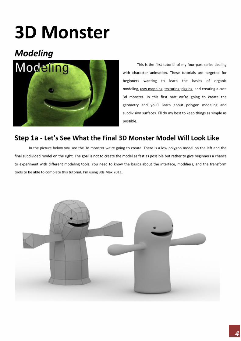
Step 1a - Let’s See What the Final 3D Monster Model Will Look Like
In the picture below you see the 3d monster we’re going to create. There is a low polygon model on the left and the
final subdivided model on the right. The goal is not to create the model as fast as possible but rather to give beginners a chance
to experiment with different modeling tools. You need to know the basics about the interface, modifiers, and the transform
tools to be able to complete this tutorial. I’m using 3ds Max 2011.

5
Step 2a - Reference Image Setup in 3ds Max I recommend using reference photos/images whenever possible to make the modeling process easier. I have prepared
two images that you can use while modeling the monster. Please download the following files:
3D monster – front view (http://www.polygonblog.com/wp-content/uploads/2010/08/3d-monster-model-front.jpg)

6
3D monster – left view (http://www.polygonblog.com/wp-
content/uploads/2010/08/3d-monster-model-left.jpg).
Create a Plane (Create panel > Geometry > Standard Primitives >
Plane) in the front viewport . Modify the Plane (Make a selection >
Modify panel ) according to the following parameters :
Length: 200
Width: 200
Length Segs: 1
Width Segs: 1
Create another Plane in the left viewport with the same
settings. Now we have two planes in the scene. Go to the left
viewport and align (Tools > Align > Align) the planes vertically
(Y.axis).
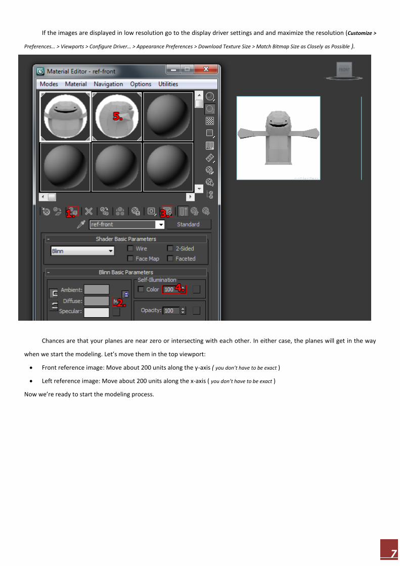
Let’s apply the reference images to the planes. Open Material
Editor (Press ‘m’ in keyboard ) and create the materials for the
planes:
1. Select the plane you created in the front viewport and
assign the material to it
2. Add the diffuse map ( Maps > Standard > Bitmap > 3d-
monster-model-front.jpg )
3. Enable “Show Standard Map in Viewport” ( Makes the texture visible in shaded viewports )
4. Self-Illumination: 100 ( Makes the texture easier to see in the viewports )
5. Select another material slot and create the material for the other plane as well
7
If the images are displayed in low resolution go to the display driver settings and and maximize the resolution (Customize >
Preferences… > Viewports > Configure Driver… > Appearance Preferences > Download Texture Size > Match Bitmap Size as Closely as Possible ).
Chances are that your planes are near zero or intersecting with each other. In either case, the planes will get in the way
when we start the modeling. Let’s move them in the top viewport:
Front reference image: Move about 200 units along the y-axis ( you don’t have to be exact )
Left reference image: Move about 200 units along the x-axis ( you don’t have to be exact )
Now we’re ready to start the modeling process.

8
Step 3a - Useful Keyboard Shortcuts in 3ds Max
There are some keyboard shortcuts that are extremely useful during the modeling process:
F3 – Shaded view on/off
F4 – Edged faces on/off ( matters only when the shaded view is on )
ALT Q – Isolate selected object ( There is often a need to orbit around the model during the modeling process. At certain angles the
reference planes might get in the way and that’s when the isolation mode becomes handy )
ALT X – Selected object becomes transparent
1-5 – In Edit Poly modifier you can quickly switch between different sub-object levels by pressing 1-5 in keyboard
Step 4a - Start the Modeling
We’re going to model polygon by polygon, so let’s create the very first polygon to have something to work with. Create a
small Plane ( Create panel > Geometry > Standard Primitives > Plane ) in the front viewport and apply ( Make a selection > Modify panel ) the
following parameters to it:
Length Segs: 1
Width Segs: 1
Add Edit Poly modifier to it ( Make a selection > Modify panel > Modifier List > Object-Space Modifiers > Edit Poly ). We’re going to
start the modeling from the lower lip. Activate the vertex sub-object level and move the vertices according to picture below. I
recommend concentrating on one vertex at a time. First position the vertex in the front viewport and then in the left viewport.
9
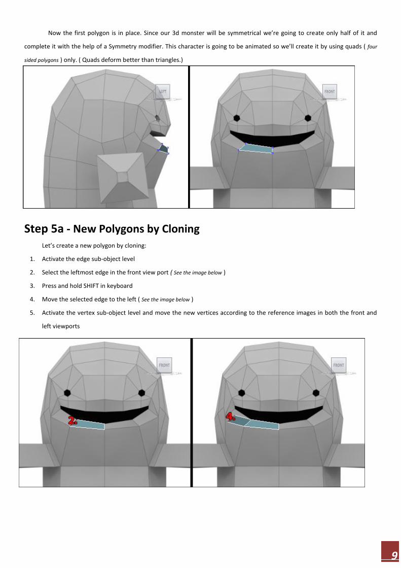
Now the first polygon is in place. Since our 3d monster will be symmetrical we’re going to create only half of it and
complete it with the help of a Symmetry modifier. This character is going to be animated so we’ll create it by using quads ( four
sided polygons ) only. ( Quads deform better than triangles.)
Step 5a - New Polygons by Cloning Let’s create a new polygon by cloning:
1. Activate the edge sub-object level
2. Select the leftmost edge in the front view port ( See the image below )
3. Press and hold SHIFT in keyboard
4. Move the selected edge to the left ( See the image below )
5. Activate the vertex sub-object level and move the new vertices according to the reference images in both the front and
left viewports
10
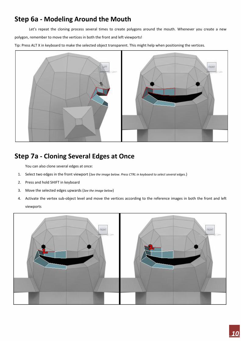
Step 6a - Modeling Around the Mouth Let’s repeat the cloning process several times to create polygons around the mouth. Whenever you create a new
polygon, remember to move the vertices in both the front and left viewports!
Tip: Press ALT X in keyboard to make the selected object transparent. This might help when positioning the vertices.
Step 7a - Cloning Several Edges at Once
You can also clone several edges at once:
1. Select two edges in the front viewport (See the image below. Press CTRL in keyboard to select several edges.)
2. Press and hold SHIFT in keyboard
3. Move the selected edges upwards (See the image below)
4. Activate the vertex sub-object level and move the vertices according to the reference images in both the front and left
viewports

11
Step 8a - Cloning Polygons
So far we’ve created new polygons by cloning edges but we can also clone polygons:
1. Activate polygon sub-object level
2. Select two polygons ( See the image below )
3. Press and hold SHIFT in keyboard
4. Move the selected polygons upwards. Select ‘Clone To Element’ in the new dialog.
5. Remember to move the vertices in both viewports ( See the image below )
Step 9a - The Bridge Tool Whenever there are two border edges that we want to connect with a polygon, we can use the Bridge tool:
1. Activate edge sub-object level and make sure you have nothing selected ( keyboard shortcut for deselect is CTRL d )
2. Activate the Bridge tool ( Edit Poly > Edit Edges > Bridge )
3. Click on the border edge in the front viewport ( See the image below )
4. Click on the other border edge ( See the image below )
5. Repeat the process on the left side of the eye as well
12
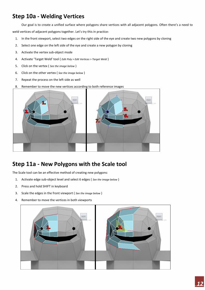
Step 10a - Welding Vertices Our goal is to create a unified surface where polygons share vertices with all adjacent polygons. Often there’s a need to
weld vertices of adjacent polygons together. Let’s try this in practice:
1. In the front viewport, select two edges on the right side of the eye and create two new polygons by cloning
2. Select one edge on the left side of the eye and create a new polygon by cloning
3. Activate the vertex sub-object mode
4. Activate ‘Target Weld’ tool ( Edit Poly > Edit Vertices > Target Weld )
5. Click on the vertex ( See the image below )
6. Click on the other vertex ( See the image below )
7. Repeat the process on the left side as well
8. Remember to move the new vertices according to both reference images
Step 11a - New Polygons with the Scale tool
The Scale tool can be an effective method of creating new polygons:
1. Activate edge sub-object level and select 6 edges ( See the image below )
2. Press and hold SHIFT in keyboard
3. Scale the edges in the front viewport ( See the image below )
4. Remember to move the vertices in both viewports

13
Step 12a - Modeling by Cloning Let’s clone some polygons in the left viewport:
1. Select 5 edges ( See the image below )
2. Press and hold SHIFT in keyboard
3. Move the edges to the left
4. Move the vertices according to the reference images ( See the image below )
Step 13a - Symmetry and TurboSmooth Modifiers
This is actually an optional step but highly recommended nevertheless. The idea of this tutorial is to create a half of a low
polygon model, complete it with the Symmetry modifier, and smoothen the surface with the Turbosmooth modifier. I’ll show
you how we can see the final surface while working on a low poly model:
1. Deactivate any sub-object level and go to the front viewport.
2. Clone the whole model by moving it while pressing SHIFT in keyboard. Select ‘Reference’ in the clone options dialog.
3. Apply Symmetry modifier to the reference copy ( Make a selection > Modify panel > Modifier List > Object-Space Modifiers >
Symmetry ). If the model disappears, activate Flip ( Symmetry > Mirror Axis > Flip ).
4. Activate mirror sub-object level in the Symmetry modifier and align the mirror plane to the right side of the model. The
vertices in the middle are welded together.
5. Deactivate mirror sub-object level and add Turbosmooth modifier ( If you see a seam in the middle, all vertices haven’t
been welded and you have to move the mirror in the Symmetry modifier ).
6. Set Iterations value ( in Turbosmooth modifier ) to 1-3 depending on your needs and computer power.
Now you continue working with the original low poly monster model and you see the changes in the smoothed model in real
time. If the smoothed model gets in the way you can just move or hide it. ( It’s also possible to add the modifiers to the or iginal
model you are working on, but personally I find that method more troublesome. )

14
Step 14a - Modeling the Rest of the Head Now you know everything you need to know to go on. Complete the rest of the head as you see fit. The front reference
image doesn’t help you much when you create the back of the head. You just have to create new polygons, orbit around the
head, and move the vertices. Remember to weld vertices together when necessary. If it feels hard, remember to concentrate on
a one polygon at a time. Be patient and move the vertices until you get a nice round head. This is what polygon modeling is all
about.
Step 15a - Modeling the Torso Now the hardest part is over. The rest of this 3d monster model is pretty simple to create. Let’s complete the torso:
1. Activate the edge sub-object level and select 5 edges ( See the image below )
2. Clone the edges downwards
3. Move the vertices according to the reference images
15
Repeat the cloning two times and create the bottom of the monster according to the image below. Cloned edges and
use Bridge tool when you can.
Step 16a - Creating the Arm
The arm is really easy to create with Extrude and Bevel tools:
1. Activate the polygon sub-object level
2. Activate Extrude tool ( Edit Poly > Edit Polygons > Extrude )
3. Click and drag on top of a polygon ( See the image below )
Make sure to extrude the polygon only a little. We want a relatively sharp joint here so we need two edges that are close to each
other. If you are not sure what I’m talking about, look at the smoothed model while extruding and compare different extrusion
values.
16
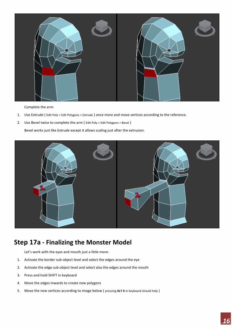
Complete the arm:
1. Use Extrude ( Edit Poly > Edit Polygons > Extrude ) once more and move vertices according to the reference.
2. Use Bevel twice to complete the arm ( Edit Poly > Edit Polygons > Bevel )
Bevel works just like Extrude except it allows scaling just after the extrusion.
Step 17a - Finalizing the Monster Model
Let’s work with the eyes and mouth just a little more:
1. Activate the border sub-object level and select the edges around the eye
2. Activate the edge sub-object level and select also the edges around the mouth
3. Press and hold SHIFT in keyboard
4. Move the edges inwards to create new polygons
5. Move the new vertices according to image below ( pressing ALT X in keyboard should help )
17
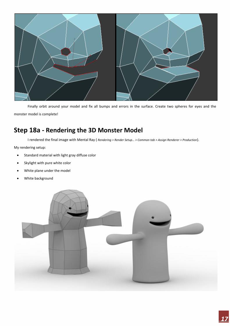
Finally orbit around your model and fix all bumps and errors in the surface. Create two spheres for eyes and the
monster model is complete!
Step 18a - Rendering the 3D Monster Model
I rendered the final image with Mental Ray ( Rendering > Render Setup… > Common tab > Assign Renderer > Production).
My rendering setup:
Standard material with light gray diffuse color
Skylight with pure white color
White plane under the model
White background

18
Unwrapping This is the second tutorial of my four part series
dealing with character animation. These tutorials are
targeted for beginners wanting to learn the basics of organic
modeling, unwrapping, texturing, character rigging,
and creating a cute 3d monster. In this second part we’re
going to unwrap the character. You’ll learn about UVW
texture coordinates and unwrapping. I’ll do my best to keep
things as simple as possible. I’m using 3ds Max 2011.
Step 1b - What is Unwrapping?
In 3d graphics, mapping coordinates ( often called UVW coordinates or just UVWs ) define how the texture is wrapped around
the model. Unwrapping means laying out the mapping coordinates so that texture painting can be done. While unwrapping a
model one should pay attention to two things: stretching and seams. Naturally there must be seams when a 2d texture is
wrapped around a 3d model. However, during the unwrapping process, one can define the amount and position of the seams.
The goal is to have as few seams as possible and to hide them as well as possible (in the back of the model, under arms etc.).
The UVW mapping coordinates can ( and often do) make the texture stretch. During the unwrapping, the stretching should be
minimized by moving the mapping coordinates. Often when there are lot of seams there aren’t that much stretching and vice
versa. One must make a compromise between these two issues. In my opinion seams is the lesser evil and can be fixed easily
with a 3d paint as you’ll see in my upcoming texture painting tutorial.
In the picture below you see the result of this tutorial. There are the unwrapped UVW coordinates on the left and the
model with the UVWs and a checker texture on the right.
19
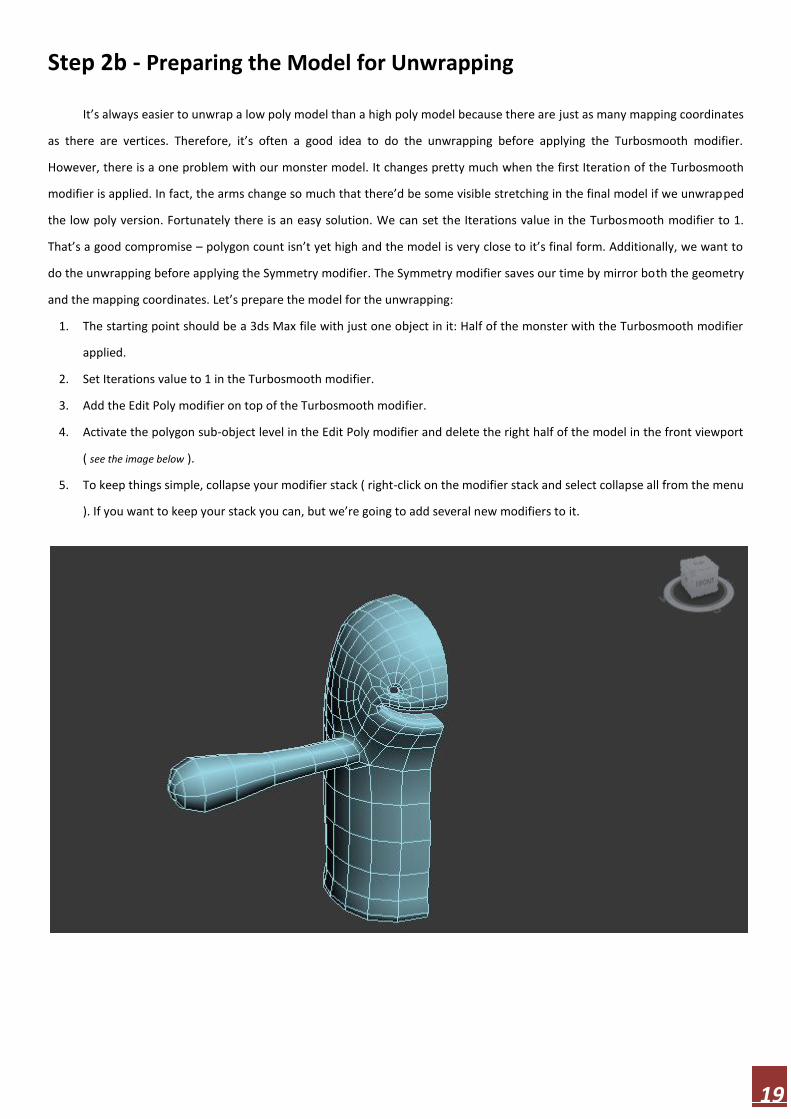
Step 2b - Preparing the Model for Unwrapping
It’s always easier to unwrap a low poly model than a high poly model because there are just as many mapping coordinates
as there are vertices. Therefore, it’s often a good idea to do the unwrapping before applying the Turbosmooth modifier.
However, there is a one problem with our monster model. It changes pretty much when the first Iteration of the Turbosmooth
modifier is applied. In fact, the arms change so much that there’d be some visible stretching in the final model if we unwrapped
the low poly version. Fortunately there is an easy solution. We can set the Iterations value in the Turbosmooth modifier to 1.
That’s a good compromise – polygon count isn’t yet high and the model is very close to it’s final form. Additionally, we want to
do the unwrapping before applying the Symmetry modifier. The Symmetry modifier saves our time by mirror both the geometry
and the mapping coordinates. Let’s prepare the model for the unwrapping:
1. The starting point should be a 3ds Max file with just one object in it: Half of the monster with the Turbosmooth modifier
applied.
2. Set Iterations value to 1 in the Turbosmooth modifier.
3. Add the Edit Poly modifier on top of the Turbosmooth modifier.
4. Activate the polygon sub-object level in the Edit Poly modifier and delete the right half of the model in the front viewport
( see the image below ).
5. To keep things simple, collapse your modifier stack ( right-click on the modifier stack and select collapse all from the menu
). If you want to keep your stack you can, but we’re going to add several new modifiers to it.
20
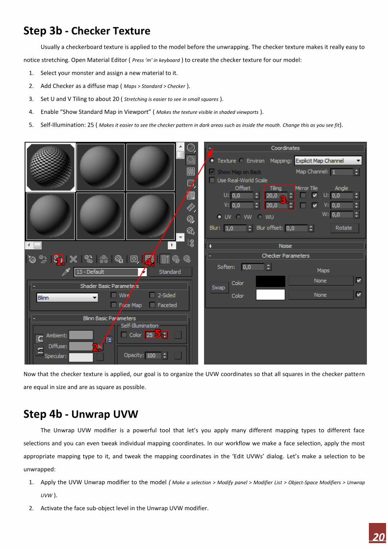
Step 3b - Checker Texture Usually a checkerboard texture is applied to the model before the unwrapping. The checker texture makes it really easy to
notice stretching. Open Material Editor ( Press ‘m’ in keyboard ) to create the checker texture for our model:
1. Select your monster and assign a new material to it.
2. Add Checker as a diffuse map ( Maps > Standard > Checker ).
3. Set U and V Tiling to about 20 ( Stretching is easier to see in small squares ).
4. Enable “Show Standard Map in Viewport” ( Makes the texture visible in shaded viewports ).
5. Self-Illumination: 25 ( Makes it easier to see the checker pattern in dark areas such as inside the mouth. Change this as you see fit).
Now that the checker texture is applied, our goal is to organize the UVW coordinates so that all squares in the checker pattern
are equal in size and are as square as possible.
Step 4b - Unwrap UVW
The Unwrap UVW modifier is a powerful tool that let’s you apply many different mapping types to different face
selections and you can even tweak individual mapping coordinates. In our workflow we make a face selection, apply the most
appropriate mapping type to it, and tweak the mapping coordinates in the ‘Edit UVWs’ dialog. Let’s make a selection to be
unwrapped:
1. Apply the UVW Unwrap modifier to the model ( Make a selection > Modify panel > Modifier List > Object-Space Modifiers > Unwrap
UVW ).
2. Activate the face sub-object level in the Unwrap UVW modifier.

21
3. Select everything except the arm ( Turn ‘Ignore Backfacing’ off to speed up the selection process. You can name your face selection using
the ‘Named Selection Sets’ function on the main toolbar. It makes it easy to return to your selection. ). Orbit around the model to make
sure you haven’t missed anything.
Step 5b - Pelt Mapping
In this tutorial we’re going to use Pelt mapping. Pelt mapping is a special mapping type that is well suited for organic
models. Pelt mapping tools let us define the texture seams and stretch out the UVW coordinates into a flat, unified map:
1. While the torso is still selected, click ‘Pelt’ ( Unwrap UVW> Map Parameters > Pelt ). In the ‘Edit UVWs’ dialog you see the UVW
coordinates in the middle and a circular stretcher around it. The points in the stretcher are connected to the UVW map
seam. The job of the stretcher is to pull the UVW map flat. The stretcher can be manipulated but in this case there’s no
need.
2. Look at the checker pattern in your model. There is serious stretching at the top and at the bottom of the model.
3. Click ‘Start Pelt’ , let the simulation run for a few seconds, and click ‘Stop Pelt’.
4. Look at the checker pattern in your model. It looks better, but there is still stretching and and squares aren’t uniform in
size.
5. Click ‘Start Relax’ and let the simulation run some time but stop it before the UVW vertices in the corner of the mouth
overlap too much ( see the image below ).
6. Look at the checker pattern in your model. If it looks ok click ‘Commit’.

22
Step 6b - Edit UVWs Dialog
The face selection in the Unwrap UVW has been translated to a UVW coordinate selection in the ‘Edit UVWs’ dialog.
Before manipulating the UVWs, let’s apply a few settings to make things a little simpler:
1. Activate ‘Filter Selected Faces’ in the bottom of the dialog. ( Hides all UVWs except the ones we have selected ).
2. Click ‘Options…’ in the bottom of the dialog to expand the options panel.
3. Turn ‘Tile Bitmap’ off in ‘Bitmap Options’. ( Makes the whole dialog easier to understand ).
4. Turn ‘Constant Update’ on in Viewport Options. ( Enables real time updates when moving UVWs ).
5. Use the Move and Scale tools to fit the selected UVWs inside the texture boundaries. Also, rotate the UVW map so that
the right side is as vertical as possible ( It makes the stitching in step 11 a little easier. ).

23
Step 7b - Dealing with Overlapping UVW Coordinates
The checker pattern should look really good, but unfortunately there might be some overlapping UVW coordinates or
inverted faces. Let’s run two automatic error checking routines to find these problems:
1. Select Inverted Faces ( ‘Edit UVWs’ Dialog > Select > Select Inverted Faces ).I didn’t find any but if you do, fix it (see steps 3 -4 ).
2. Select Overlapped Faces ( ‘Edit UVWs’ Dialog > Select > Select Overlapped Faces ).In my model there is one overlapped face in the
corner of the mouth ( Overlapping UVW coordinates are a problem because they use the same portion of the texture ). Let’s zoom to the
problem area and fix it.
3. Activate the vertex sub-object level in the Unwrap UVW modifier.

24
4. Move the vertices so that the problematic UVW faces look more like rectangles ( See the image below ). Check your model to
make sure the checker pattern didn’t get messed up. When you’re done just close the ‘Edit UVWs’ dialog.
Step 8b - Defining UV Seams for Pelt Mapping
Now the unwrapping of the body is complete and we go on with the arm. By default the only seam in the arm is at the
edge of our selection. That isn’t enough. The stretcher wouldn’t be able pull the UWV map flat. Try to visualize it in your head:
It’s like trying to turn a sock into a flat piece of fabric without any cutting. But with just one cut we could do it, right? So let’s
define one seam:
1. Activate the face sub-object level in the Unwrap UVW modifier and select the faces of the arm. Orbit around the model to
make sure you haven’t missed anything.
2. Activate ‘Point to point Seam’ ( Unwrap UVW > Map Parameters > Point to Point Seam ) and define the seam for pelt mapping.
Just click on vertices and a seam is traced between them. Defined seams are shown in blue color (See the image below ).
There should be 10 edges in your seam. Make the seam under the arm, not on top of it. If you make a mistake you can
activate ‘Edit Seams’ ( Unwrap UVW > Map Parameters > Edit Seam) and remove unwanted seams by clicking on them while
pressing Alt in keyboard.

25
Step 9b - Unwrapping the Arm From now on the pelt mapping process is exactly the same as with the torso except there probably won’t be any
overlapped nor inverted faces.
1. While the arm is still selected, click ‘Pelt’ ( Unwrap UVW > Map Parameters > Pelt ).
2. Click ‘Start Pelt’, let the simulation run for a few seconds, and click ‘Stop Pelt’.
3. Look at the checker pattern in your model. There is probably stretching and the squares aren’t uniform in size.
4. Click ‘Start Relax’, let the simulation run for a few seconds, and click ‘Stop Relax. ( see the image below ).
5. Look at the checker pattern in your model. If it looks ok click ‘Commit’.
6. Move and scale your UVW selection so that it doesn’t overlap with the UVWs of the torso.
7. Scale the UVWs of the arm until the size of the squares is the same as in the torso ( you can choose whether you work in face,
edge, or vertex level. Personally I prefer the vertex level )
8. Arrange to UWV coordinates for example like in image below ( you can easily select a whole cluster of UVWs by activating ‘Select
Element’ under ‘Selection Modes’ in the bottom of the dialog ) and close the dialog.

26
Step 10b - Mirroring the UV Coordinates and the Geometry Now the unwrapping is done and we’re ready to apply the Symmetry modifier:
1. Go to the front viewport and apply the Symmetry modifier ( Make a selection > Modify panel > Modifier List > Object-Space Modifiers
> Symmetry ). If the model disappears, activate Flip ( Symmetry > Mirror Axis > Flip ).
2. Activate the mirror sub-object level in the Symmetry modifier and align the mirror plane to the right side of the model.
The vertices in the middle are welded together. Deactivate mirror sub-object level.
Step 11b - Tweaking the UVW Coordinates
Add another Unwrap UVW modifier on top of the Symmetry modifier ( Make a selection > Modify panel > Modifier List > Object-
Space Modifiers > Unwrap UVW ). Click ‘Edit…’ in the Unwrap UVW modifier to open the ‘Edit UVWs’ dialog (UVW Unwrap > Parameters >
Edit… ). The UVW layout looks exactly the same as before the Symmetry modifier, but it’s not. The UVW coordinates of the both
sides are exactly on top of each other and therefore use the same portion of the texture. This would be ok if we wanted the
texturing to be perfectly symmetrical. Usually you want to separate the coordinates to avoid perfect symmetry:
1. Activate ‘Select Element’ in the ‘Selection Modes’ at the bottom of the ‘Edit UVWs’ dialog.
2. Click on the UVW map of the arm and move it to the right. Now you have separated the UVW clusters of the arms. Click
‘Mirror Horizontal’ in the top of the dialog ( this isn’t necessary but in my opinion a logical way of arranging the UVW coordinates ).
Move the UVW clusters of the arms as you see fit. Just make sure to keep them separated and inside the texture
boundaries.
3. Click on the UVW map of the torso and move it to the right.
4. Click ‘Mirror Horizontal’ in the top of the dialog to mirror the selected UVWs horizontally.
5. Move the UVW clusters of the torso close the each other so that the middle vertices overlap ( see the image below ). These
UVW coordinate clusters have a common seam in the middle and therefore can be welded together.

27
6. Deactivate ‘Select Element’ in the ‘Selection Modes’ at the bottom of the dialog and weld the vertices on the common
seam together ( see the image below ): select two vertices at a time, double click on them, and select ‘Weld selected’ from
the menu. If the weld doesn’t work, the vertices are too far apart and you must increase the ‘Weld Threshold’ in the
‘Unwrap Editor Options’ at the bottom of the dialog.
7. If the welding caused stretching in the middle, go ahead and move UVW vertices to fix it.
8. It’s possible that one or more UVW clusters are inverted which might cause problems with bump mapping. Activate the
face sub-object level and click ‘Select Inverted Faces’ ( ‘Edit UVWs’ Dialog > Select > Select Inverted Faces ). If any of the UVW
clusters turns red, just mirror it horizontally and you’re done.
9. Move and scale the UVW coordinate clusters so that they fill as much of the texture area as possible. There is a tool for
that called ‘Pack UVs’ ( Edit UVWs Dialog > Tools > Pack UVs… ) but let’s do it by hand. Move and scale the UVW clusters as you
see fit but whenever you scale, scale everything to keep the coordinate resolution uniform.
Step 12b - Good to Know
If you just want to finish this, skip to step 13, but if you’d like to learn about the other mapping types, read on. In this
tutorial we used Pelt mapping. Pelt mapping works well but sometimes there is a need also for the traditional mapping types:
planar, cylindrical, spherical, and box. The workflow with these mapping types is a little different:

28
1. You make a face selection.
2. You apply the appropriate mapping type ( depends on the form of the selection, for example cylindrical selection like an arm works well
with the cylindrical mapping type ).
3. You move, scale, and rotate the mapping gizmo to minimize stretching and to position seams ( With these mapping types you
can’t define seams like we did with Pelt mapping. Instead, seams are derived from the mapping gizmo. You can just manipulate the gizmo to
affect the placement and the amount of seams ).
4. You continue in the ‘Edit UVWs’ Dialog and move UVWs to minimize stretching and weld them to get rid of seams.
Sometimes you must move UVW vertices one by one but often the Relax tool ( Edit UVWs Dialog > Tools > Relax… ) solves
stretching automatically. The Relax tool works like the Relax in the Pelt mapping dialog. First you select UVWs in the
problematic area ( and maybe little around it ) and then you run the Relax to modify the spacing of the selected UVWs for the
purpose of minimizing stretching. Trial and error method works well with the Relax tool. Just try different selections and
different settings.
Step 13b - Turbosmooth
Now the UVW Unwrapping is complete. Add the Turbosmooth modifier to the model and set the Iterations value to 1-2
depending on your needs.

29
Texturing This is the third tutorial in my four part series
dealing with character animation. These tutorials are
targeted to beginners wanting to learn the basics oforganic
modeling, unwrapping, texturing, rigging, and creating a cute
3d monster. In this third part we’re dealing with texturing.
You’ll learn how to create and apply textures with Viewport
Canvas. I’ll do my best to keep things as simple as possible.
I’m using 3ds Max 2011 and Photoshop.
Step 1c - What is Texturing?
In 3d graphics, texturing means the process of creating and applying textures to the model. In fact, the term texturing
consist of two things: UVW mapping and texture painting. UVW mapping was covered in my previous tutorial and this one will
concentrate on the texture painting. We’re going to create the texture by using Photoshop and Viewport Canvas. Viewport
Canvas is a 3D paint inside of 3ds Max. In the picture below you see the result of this tutorial.
Step 2c - Mental Ray Renderer
We’re going to render the scene with Mental Ray. By default 3ds Max uses Scanline renderer so we have to change
that. Change the renderer to Mental Ray ( Rendering > Render Setup… > Common tab > Assign Renderer > Production > mental ray Renderer ).

30
Step 3c - Prepare the Model for Texturing We continue from the unwrapping tutorial. As a starting point we should have the unwrapped model with the
Turbosmooth modifier applied. We don’t need the checker material anymore so let’s get rid of that:
1. Open Material Editor ( Press ‘m’ in keyboard ).
2. Select a new (empty) material slot.
3. Click “Get Material” button and select ( doubleclick ) ‘Arch & Design (mi)’ from the list ( Materials > mental ray > Arch &
Design ).
4. Assign the new material to the monster ( drag and drop ).
Step 4c - Texturing with Viewport Canvas
Viewport Canvas is a new feature in 3ds Max. I think it was introduced in 3ds Max 2010 and in 2011 it has been
completely upgraded. If you don’t have 3ds Max 2011 you unfortunately can’t really follow this tutorial. If you have Photoshop,
you could render a UVW template ( Unwrap UVW > Parameters > Edit… > Tools > Render UVW Template… ) and try to apply the ideas on
top of that. Anyway, let’s launch Viewport Canvas and start painting.
1. Select the monster model.
2. Open Viewport Canvas ( Tools > Viewport Canvas… ).
3. Click on the ‘Paint’ tool ( to activate the paint mode ).
4. Select ‘Diffuse Color Map: …’ from the menu ( Viewport Canvas needs to know which map channel we’re painting.). A new dialog
appears.
5. Set the size of the texture map to 2000×2000.
6. Select the folder for your file, name your file, and select PNG as file format ( I recommend choosing RGB 24 bit as color depth.
Alpha channel is not needed. ).
7. Click ‘OK’ to save the file.

31
Step 5c - Starting Texture Painting
Let’s use the Fill and Gradient tools to give some color to our monster:
1. Go to the front viewport.
2. Select green color ( R103 G132 B58 ).
3. Active the Fill tool and click on top of your monster.
4. Open the Layers dialog ( Layers work just like in Photoshop ).
5. Create and activate a new layer.
6. Select dark green color (R44 G56 B24).
7. Activate the Gradient tool. Click and hold on the bottom of the monster, drag upwards, and release when you’re satisfied
with the gradient.

32
Step 6c - Saving the Texture
Deactivate the Gradient tool ( or whatever paint tool you have currently activated ). A new dialog appears. At the moment
there are two layers but layers cannot be saved in a PNG file so something has to be done. There are several options and they
are all pretty self-explanatory. We select ‘Save as PSD and replace texture in material’. I think that’s usually the most preferred
choice. Now the file is saved as PSD and applied to the diffuse color channel in the material. You might wonder why we didn’t
save the file as PSD in the first place. Unfortunately 3ds Max doesn’t allow that at the moment but I’m guessing it will change
soon.
Step 7c - Working with Photoshop
Next we’re going to work with Photoshop to create some texture:
1. Open this file in Photoshop
2. Desaturate the image ( Image > Adjustments > Desaturate )
3. Apply ‘Palette Knife’ filter ( Filter > Artistic > Palette Knife… ). I used values ( 15, 3, 0 ). The idea is to have a painted look to the
texture.
33
4. The image size should be the same as our texture size in 3ds Max. Adjust if necessary.
5. Save the file and return to 3ds Max.
Step 8c - Apply the Texture to the Model
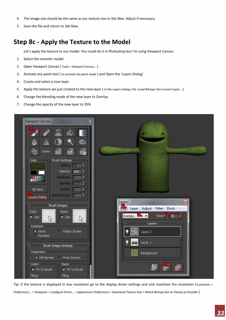
Let’s apply the texture to our model. You could do it in Photoshop but I’m using Viewport Canvas:
1. Select the monster model.
2. Open Viewport Canvas ( Tools > Viewport Canvas… ).
3. Activate any paint tool ( to activate the paint mode ) and Open the ‘Layers Dialog’.
4. Create and select a new layer
5. Apply the texture we just created to the new layer ( In the Layers Dialog: File >Load Bitmap Into Current Layer… )
6. Change the blending mode of the new layer to Overlay
7. Change the opacity of the new layer to 35%
Tip: If the texture is displayed in low resolution go to the display driver settings and and maximize the resolution (Customize >
Preferences… > Viewports > Configure Driver… > Appearance Preferences > Download Texture Size > Match Bitmap Size as Closely as Possible ).

34
Step 9c - Removing Texture Seams Now the monster has a nice painted look but unfortunately the texture seams are clearly visible. Next we’re going to do
something that would be really difficult in Photoshop but really easy in 3d paint. We’re going to use the Clone tool to paint over
the seams:
1. Activate the Clone tool.
2. Orbit around the model to get a good view of a seam.
3. Select suitable brush radius ( I recommend using a pretty large brush ). Tip: The shortcut to brush radius is CTRL + SHIFT + Left
click & drag.
4. Set the sampling point by positioning the pointer to suitable area on the monster and ALT-clicking.
5. Paint over the seam.
6. Use this method to remove all the seams. You must set the sampling point again several times until you are done.
Convincing cloning takes usually some time. Experiment with the hardness of the brush as well.
Step 10c - Creating Details
Let’s create more details by adding another texture to our layer stack ( just like in step 6 ):
1. Load this (http://www.polygonblog.com/wp-content/uploads/2010/04/concrete-texture-high-
resolution.jpg) file.
2. Create and select a new layer ( Make sure the new layer is the topmost layer. You can change their order by dragging and
dropping ).
3. Apply the texture to the new layer ( In the Layers Dialog: File >Load Bitmap Into Current Layer… )
4. Clone the seams away
5. Change the blending mode of the new layer to Overlay
6. Change the opacity of the new layer to 30%
35
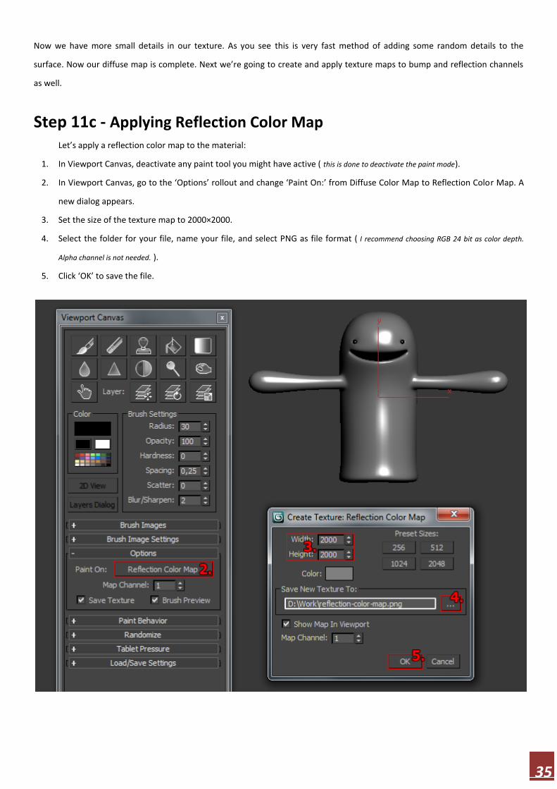
Now we have more small details in our texture. As you see this is very fast method of adding some random details to the
surface. Now our diffuse map is complete. Next we’re going to create and apply texture maps to bump and reflection channels
as well.
Step 11c - Applying Reflection Color Map
Let’s apply a reflection color map to the material:
1. In Viewport Canvas, deactivate any paint tool you might have active ( this is done to deactivate the paint mode).
2. In Viewport Canvas, go to the ‘Options’ rollout and change ‘Paint On:’ from Diffuse Color Map to Reflection Color Map. A
new dialog appears.
3. Set the size of the texture map to 2000×2000.
4. Select the folder for your file, name your file, and select PNG as file format ( I recommend choosing RGB 24 bit as color depth.
Alpha channel is not needed. ).
5. Click ‘OK’ to save the file.
36
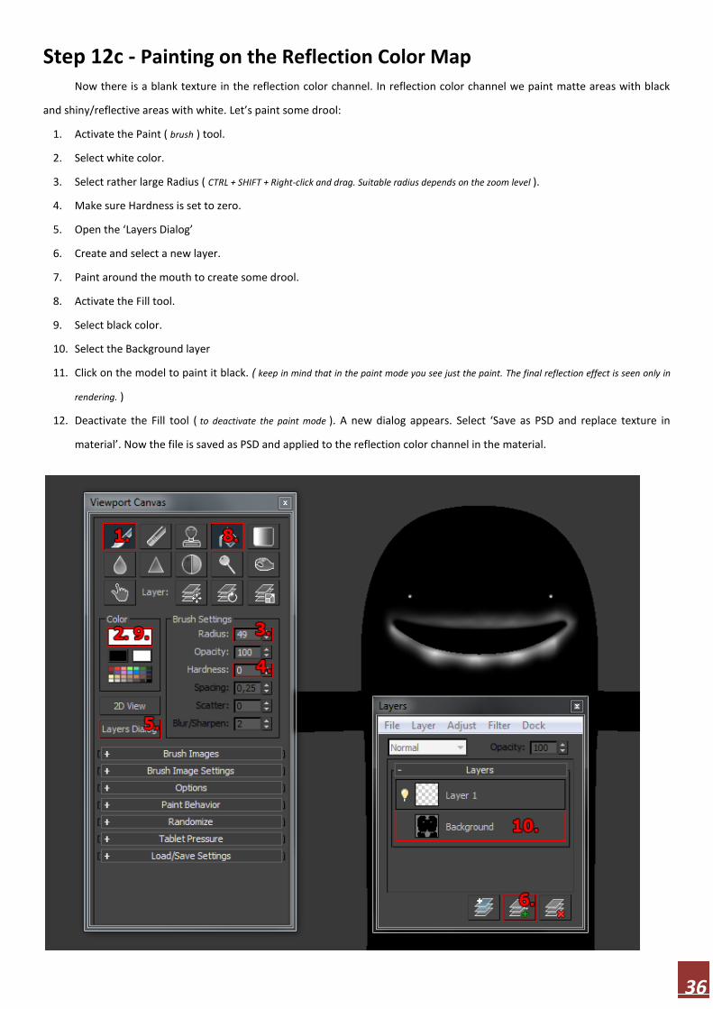
Step 12c - Painting on the Reflection Color Map Now there is a blank texture in the reflection color channel. In reflection color channel we paint matte areas with black
and shiny/reflective areas with white. Let’s paint some drool:
1. Activate the Paint ( brush ) tool.
2. Select white color.
3. Select rather large Radius ( CTRL + SHIFT + Right-click and drag. Suitable radius depends on the zoom level ).
4. Make sure Hardness is set to zero.
5. Open the ‘Layers Dialog’
6. Create and select a new layer.
7. Paint around the mouth to create some drool.
8. Activate the Fill tool.
9. Select black color.
10. Select the Background layer
11. Click on the model to paint it black. ( keep in mind that in the paint mode you see just the paint. The final reflection effect is seen only in
rendering. )
12. Deactivate the Fill tool ( to deactivate the paint mode ). A new dialog appears. Select ‘Save as PSD and replace texture in
material’. Now the file is saved as PSD and applied to the reflection color channel in the material.
37
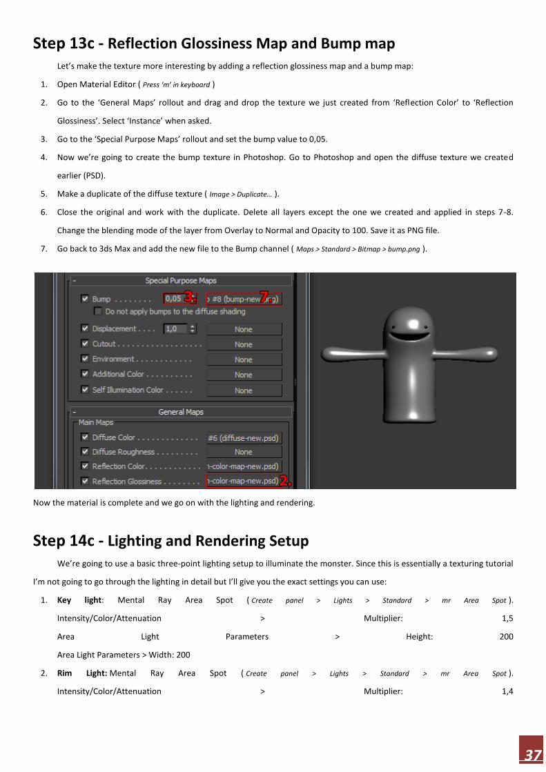
Step 13c - Reflection Glossiness Map and Bump map Let’s make the texture more interesting by adding a reflection glossiness map and a bump map:
1. Open Material Editor ( Press ‘m’ in keyboard )
2. Go to the ‘General Maps’ rollout and drag and drop the texture we just created from ‘Reflection Color’ to ‘Reflection
Glossiness’. Select ‘Instance’ when asked.
3. Go to the ‘Special Purpose Maps’ rollout and set the bump value to 0,05.
4. Now we’re going to create the bump texture in Photoshop. Go to Photoshop and open the diffuse texture we created
earlier (PSD).
5. Make a duplicate of the diffuse texture ( Image > Duplicate… ).
6. Close the original and work with the duplicate. Delete all layers except the one we created and applied in steps 7-8.
Change the blending mode of the layer from Overlay to Normal and Opacity to 100. Save it as PNG file.
7. Go back to 3ds Max and add the new file to the Bump channel ( Maps > Standard > Bitmap > bump.png ).
Now the material is complete and we go on with the lighting and rendering.
Step 14c - Lighting and Rendering Setup
We’re going to use a basic three-point lighting setup to illuminate the monster. Since this is essentially a texturing tutorial
I’m not going to go through the lighting in detail but I’ll give you the exact settings you can use:
1. Key light: Mental Ray Area Spot ( Create panel > Lights > Standard > mr Area Spot ).
Intensity/Color/Attenuation > Multiplier: 1,5
Area Light Parameters > Height: 200
Area Light Parameters > Width: 200
2. Rim Light: Mental Ray Area Spot ( Create panel > Lights > Standard > mr Area Spot ).
Intensity/Color/Attenuation > Multiplier: 1,4
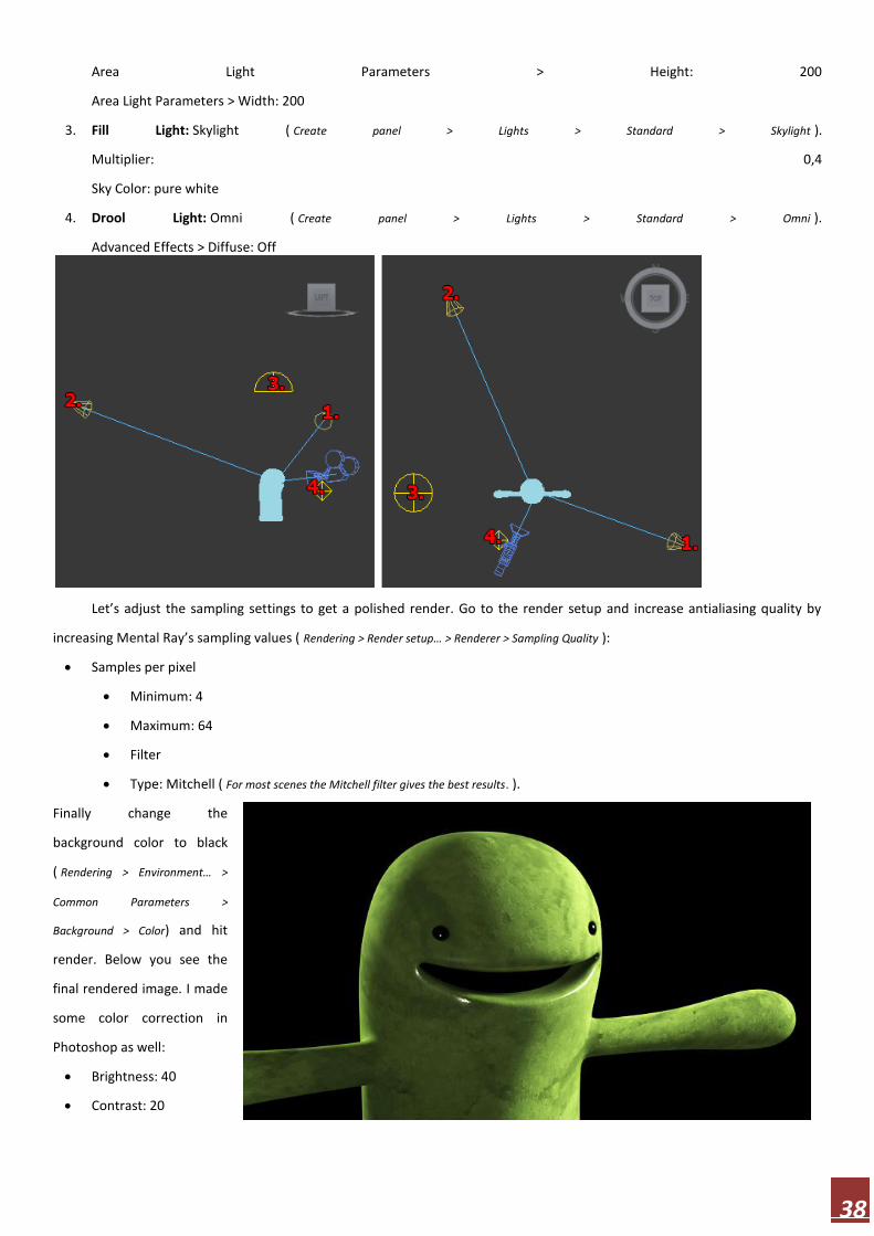
38
Area Light Parameters > Height: 200
Area Light Parameters > Width: 200
3. Fill Light: Skylight ( Create panel > Lights > Standard > Skylight ).
Multiplier: 0,4
Sky Color: pure white
4. Drool Light: Omni ( Create panel > Lights > Standard > Omni ).
Advanced Effects > Diffuse: Off
Let’s adjust the sampling settings to get a polished render. Go to the render setup and increase antialiasing quality by
increasing Mental Ray’s sampling values ( Rendering > Render setup… > Renderer > Sampling Quality ):
Samples per pixel
Minimum: 4
Maximum: 64
Filter
Type: Mitchell ( For most scenes the Mitchell filter gives the best results. ).
Finally change the
background color to black
( Rendering > Environment… >
Common Parameters >
Background > Color) and hit
render. Below you see the
final rendered image. I made
some color correction in
Photoshop as well:
Brightness: 40
Contrast: 20

39
Character Rigging
This is the fourth tutorial in my four part series
dealing with character animation. These tutorials are
targeted for beginners wanting to learn the basics
ofmodeling, uvw mapping, texturing, rigging, and creating a
cute 3d monster. In this fourth part we’re dealing with
character rigging. You’ll learn the basics of using the Morpher
and Skin modifiers to manipulate and deform a simple
character. Character rigging can be a tough subject for
beginners but I’ll do my best to keep things as simple as possible. I’m using 3ds Max 2011.
Step 1d - What is Character Rigging? In 3d animation, character rigging means the process of preparing the character for animation. The idea is to use special
helper objects and modifiers to prepare a set of tools that make the animating process as easy as possible. We’re going to rig the
character by using the Morpher modifier for the facial animation and the Skin modifier (in conjunction with bones) for the rest
of the body. In the picture below you see a character pose you can be easily do after completing this tutorial.

40
Step 2d - Facial Animation and Morpher The Morpher modifier is commonly used for lip sync and facial animation. The Morpher modifier deforms the original
object according to predefined target objects. The biggest task is the creation of the target objects ( morph targets ). The
modifier itself is really simple to use.
Step 3d - Creating Morph Targets
Let’s create the morph targets for our character:
1. Go to the front viewport and clone the monster ( Press and hold SHIFT in keyboard and move the monster ). Make sure
you make a normal copy ( not instance or reference). From now on we work on the copy.
2. Remove Turbosmooth and both Unwrap UVW modifiers from the copy.
3. Go to the Editable Poly or Edit Poly modifier ( Make a selection > Modify panel ) below the Symmetry modifier and activate the
vertex sub-object level.
4. Create a new facial expression like in picture below by moving vertices. You can freely move vertices around but make
sure the vertex count stays the same at all times. If you add or remove even one vertex, it won’t work with the Morpher
modifier ( Tip: Consider activating the polygon sub-object level and hiding part of the model to make it easier to select
vertices around the mouth. If you hide the back of the model you don’t have to worry about accidentally selecting vertices
there. )
5. Give appropriate name for your morph target such as ‘mouth afraid’.
Now we have one morph target and that’s enough for the sake of this tutorial. If you are about to create some serious
facial animation, you need more morph targets. Just create more copies from the original and create expressions like smile,
amazement, blinking eyes and so on. It’s often a good idea to create separate targets for eyes and mouth and separate targets
for the left and right side (like wink) as well to have maximum control over the expressions. The Morpher modifier lets you
combine the expressions of several different morph targets.

41
Step 4d - Using the Morpher Modifier to Animate Facial Expressions Now select the original monster model and try the Morpher modifier:
1. Apply the Morpher modifier ( Make a selection > Modify panel > Modifier List > Object-Space Modifiers > Morpher ) and move it just
below the Turbosmooth modifier.
2. Go to the ‘Channel List’ rollout and right-click on the first ‘- empty -’ slot.
3. Click on ‘Pick from Scene’ and then on the morph target (mouth afraid). Now the first morph channel is activated. Just use
the spinner to morph between the original model and the morph target. If you modify the morph target, remember to
reload it by clicking on ‘Reload All Morph Targets’ button.
Tip: Turn ‘Use Limits’ off in the ‘Global Parameters’ rollout to go beyond the 0-100 range. Try for example negative values to get
some interesting ( and maybe even useful ) results. Remember also that channel percentages can be mixed when you have
multiple morph targets.
42
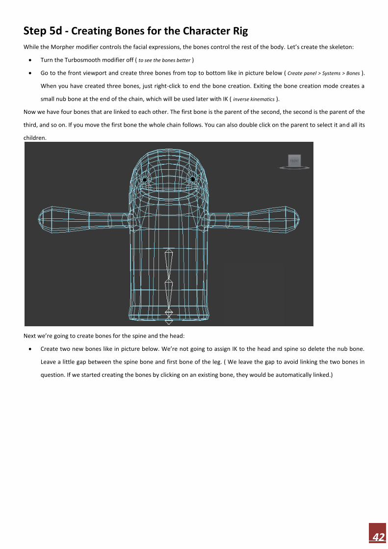
Step 5d - Creating Bones for the Character Rig While the Morpher modifier controls the facial expressions, the bones control the rest of the body. Let’s create the skeleton:
Turn the Turbosmooth modifier off ( to see the bones better )
Go to the front viewport and create three bones from top to bottom like in picture below ( Create panel > Systems > Bones ).
When you have created three bones, just right-click to end the bone creation. Exiting the bone creation mode creates a
small nub bone at the end of the chain, which will be used later with IK ( inverse kinematics ).
Now we have four bones that are linked to each other. The first bone is the parent of the second, the second is the parent of the
third, and so on. If you move the first bone the whole chain follows. You can also double click on the parent to select it and all its
children.
Next we’re going to create bones for the spine and the head:
Create two new bones like in picture below. We’re not going to assign IK to the head and spine so delete the nub bone.
Leave a little gap between the spine bone and first bone of the leg. ( We leave the gap to avoid linking the two bones in
question. If we started creating the bones by clicking on an existing bone, they would be automatically linked.)

43
Open Bone Tools ( Animation > Bone Tools… ), activate the ‘Bone Edit Mode’ and move the spine bone to meet the first bone of the
leg like in picture below. Close the Bone Tools.
Next we’ll create the arm bones. This time we want to link the arm bones to the spine so start creating the bones by clicking on
the spine bone. Create four bones ( plus the nub bone) for the left arm like in picture below.

44
Now we have all the bones we need and we just have to fit them inside the character. Go to the left viewport, select all
the bones and move them to the center of the character. Rotate the bones like in picture below. Notice how the knee bends.
We bend the bones now to make them work better with IK.
I wasn’t really sure how I should rig this weird monster character so I did the leg bones pretty much like I would for a human-like
character (except for the fact that there is only one leg). You can also create two “legs” inside the monster if you want to make it
“walk”. It all depends on how you want your character to move. Does it move by flying, jumping, crawling, walking, or by all
these means?

45
Go to the top viewport and rotate the arm bones so that they fit inside the character. Make sure the arm bends a little.
Select the whole arm by double clicking on the clavicle bone (the bone between the spine and the arm). Use the mirror tool ( The
main toolbar > Mirror ) to make a mirrored copy of the arm ( make sure to make a standard copy, not instance or reference ).
Position the new bones like in picture below.
We still have to link the right arm to the spine:
1. Go to the front viewport
2. Activate ‘Select and Link’ ( The main toolbar > Select and Link )
3. Click and hold on right clavicle bone. Drag and release on top of the spine bone. ( To check that the linking was successful,
select only the spine bone and try moving it. Both arms should follow. Undo the move. )
46
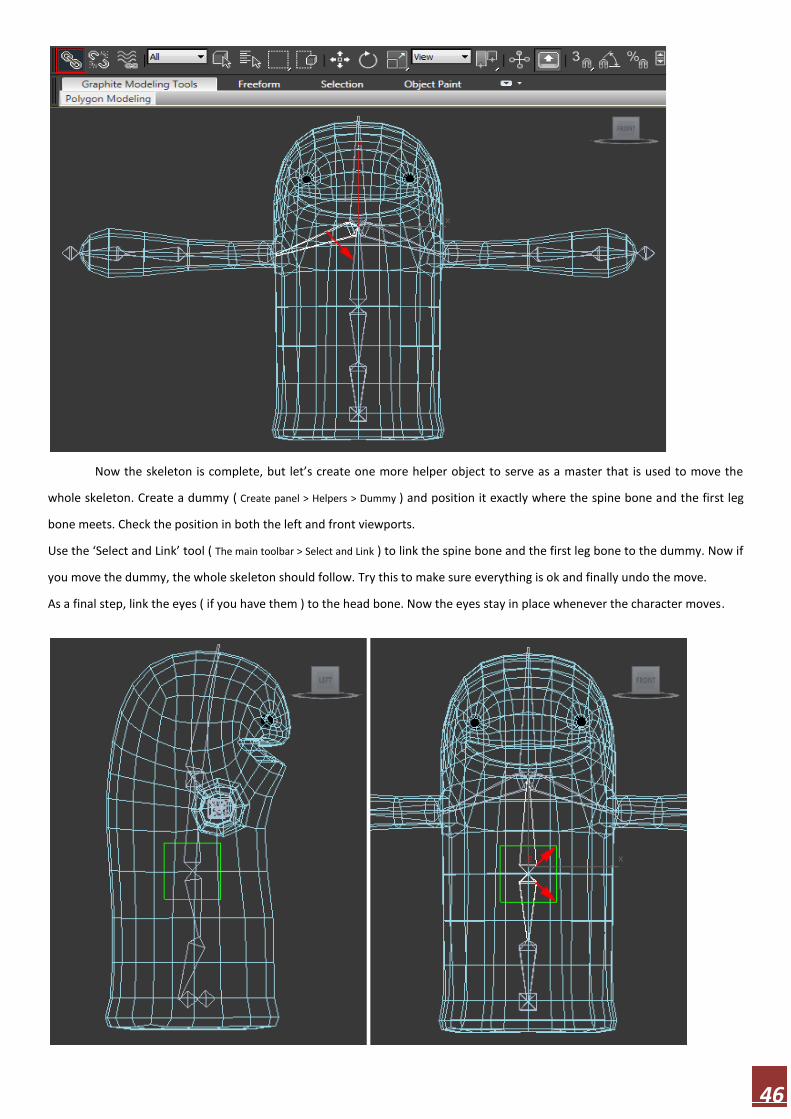
Now the skeleton is complete, but let’s create one more helper object to serve as a master that is used to move the
whole skeleton. Create a dummy ( Create panel > Helpers > Dummy ) and position it exactly where the spine bone and the first leg
bone meets. Check the position in both the left and front viewports.
Use the ‘Select and Link’ tool ( The main toolbar > Select and Link ) to link the spine bone and the first leg bone to the dummy. Now if
you move the dummy, the whole skeleton should follow. Try this to make sure everything is ok and finally undo the move.
As a final step, link the eyes ( if you have them ) to the head bone. Now the eyes stay in place whenever the character moves.
47
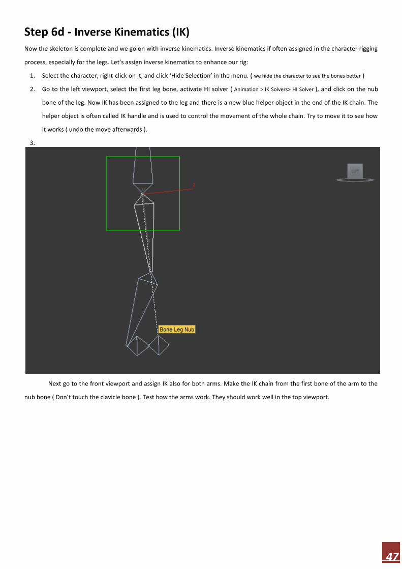
Step 6d - Inverse Kinematics (IK) Now the skeleton is complete and we go on with inverse kinematics. Inverse kinematics if often assigned in the character rigging
process, especially for the legs. Let’s assign inverse kinematics to enhance our rig:
1. Select the character, right-click on it, and click ‘Hide Selection’ in the menu. ( we hide the character to see the bones better )
2. Go to the left viewport, select the first leg bone, activate HI solver ( Animation > IK Solvers> HI Solver ), and click on the nub
bone of the leg. Now IK has been assigned to the leg and there is a new blue helper object in the end of the IK chain. The
helper object is often called IK handle and is used to control the movement of the whole chain. Try to move it to see how
it works ( undo the move afterwards ).
3.
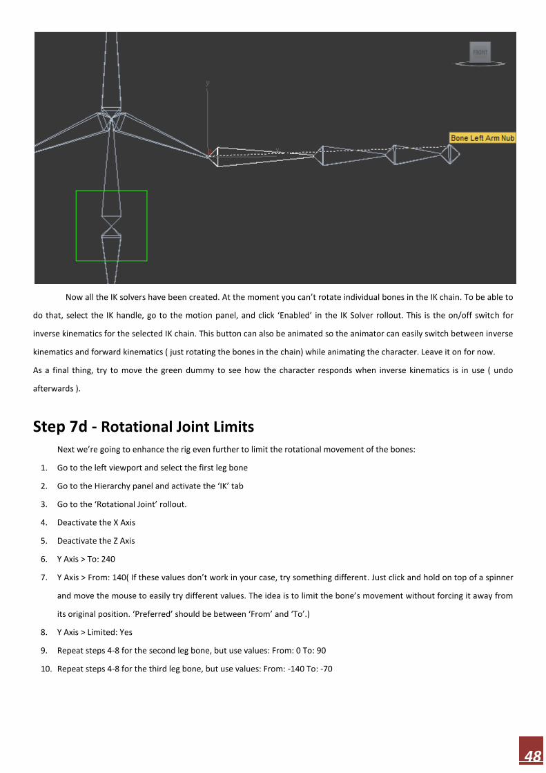
Next go to the front viewport and assign IK also for both arms. Make the IK chain from the first bone of the arm to the
nub bone ( Don’t touch the clavicle bone ). Test how the arms work. They should work well in the top viewport.
48
Now all the IK solvers have been created. At the moment you can’t rotate individual bones in the IK chain. To be able to
do that, select the IK handle, go to the motion panel, and click ‘Enabled’ in the IK Solver rollout. This is the on/off switch for
inverse kinematics for the selected IK chain. This button can also be animated so the animator can easily switch between inverse
kinematics and forward kinematics ( just rotating the bones in the chain) while animating the character. Leave it on for now.
As a final thing, try to move the green dummy to see how the character responds when inverse kinematics is in use ( undo
afterwards ).
Step 7d - Rotational Joint Limits
Next we’re going to enhance the rig even further to limit the rotational movement of the bones:
1. Go to the left viewport and select the first leg bone
2. Go to the Hierarchy panel and activate the ‘IK’ tab
3. Go to the ‘Rotational Joint’ rollout.
4. Deactivate the X Axis
5. Deactivate the Z Axis
6. Y Axis > To: 240
7. Y Axis > From: 140( If these values don’t work in your case, try something different. Just click and hold on top of a spinner
and move the mouse to easily try different values. The idea is to limit the bone’s movement without forcing it away from
its original position. ‘Preferred’ should be between ‘From’ and ‘To’.)
8. Y Axis > Limited: Yes
9. Repeat steps 4-8 for the second leg bone, but use values: From: 0 To: 90
10. Repeat steps 4-8 for the third leg bone, but use values: From: -140 To: -70

49
Now the leg bones can rotate only along Y axis and within limited range. Try to move the leg with the IK handle to see the
difference. Now It’s up to you whether you want to set the limits for the arms as well or not. You might want to come back to
this step after the skinning process to see the movement of the character while trying out different values.
Step 8d - Character Skinning / Vertex Weighting in 3ds Max
Character skinning is the process where we define how the model responds to the movement of the bones. We’ll use the
Skin modifier for that purpose. Let’s unhide the character ( Right-click on the viewport and select ‘Unhide all’ from the menu ) and go on
with the skinning process:
1. Apply the Skin modifier on top the Morpher modifier ( Make a selection > Modify panel > Modifier List > Object-Space Modifiers >
Skin )
2. In the Skin modifier in the Parameters rollout, click ‘Add’, Select all the bones except for the nub bones, and click ‘Select’.
Now the bones deform the character but it’s not pretty.
3. Now is a good time to turn the Turbosmooth modifier back on to see how the final surface deforms.(Sometimes Turbosmooth
gets messed up while working on the Skin. If this happens, just remove it and apply it again. )
4. Activate the Envelope sub-object level.
5. Select the head bone in either the viewport or in the bones list.( on envelope sub-object level we deal with envelopes. Each bone has
a capsule-shaped envelope and each envelope has an inner and an outer bound. The shape and size of the envelope determines which and how
vertices are affected when the bone moves. The influence of the bone is strongest inside the inner bound and it falls of as it approaches the outer
bound. )
6. Select the outer bound of the envelope at the top of the bone.

50
7. Change the radius of the envelope bound to 85 either by moving it or by inserting the value with keyboard(This is not exact
value. The suitable value depends on the size of your character. Just look at the picture below to size the envelope correctly ).
8. Select the outer bound of the bottom of the bone and give it the same radius. ( The idea is to make the outer bounds of the
envelopes so big that the whole width of the character falls inside of it ).
Let’s repeat the process and apply appropriate radius values for the rest of the bones ( Keep in mind that these are not exact values.
Suitable values depend on the size of your character. Just look at the picture below to size the envelopes correctly ). Make sure you change only
the radius values of the outer bounds. ( In my experience you can often get good results by adjusting only the outer bounds ):
All the leg bones, the spine bone, and the head bone: Radius: 85
Clavicle bones ( the bone between the spine and arm): Radius: 19
All arm bones except for the armpit/shoulder area: Radius: 40
Armpit/shoulder area: Radius: 19

51
Now the skinning/vertex weighting process is done. Deactivate the envelope sub-object level and try to rotate each
bone to see how the character deforms. Try also the IK handles and the master dummy. I recommend undoing all the rotations
afterwards to keep the neutral pose.
Step 9d - Character Rigging Tip: Weighting Vertices Manually
This is an optional step. Just some theory and tips. If you are lucky you can get pretty good results just by adjusting the
envelopes sizes, but there is often a need to fine tune the behavior of individual vertices as well. To weight vertices manually:
1. Turn Turbosmooth off ( to make selecting vertices easier )
2. Turn ‘Vertices’ on ( Skin > Parameters > Vertices )
3. Now you can select vertices on your character so select the vertices you would like to adjust ( selected vertices are indicated by
white small surrounding boxes )
4. Select the bone ( either in the viewport or in the bones list ) for which you want to change the vertex weights
5. Adjust the the ‘Abs. Effect’ value ( Skin > Weight Properties ) to set the new vertex weight
( The weight value of a vertex (Abs. Effect) always amounts to 1.0. This value can be divided between several bones. For
example, vertex’s weight could be 0.7 for bone-1 and 0.3 for bone-2. In that case the bone-1 would have much higher influence

52
on the vertex. In other words, the vertex would follow the movement of bone-1 much more than it would the movement of
bone-2. )
Tip: The weighting/skinning process can be made easier by animating the bones. Just animate some natural bone movements.
At first, the character will look ugly and distorted but keep in mind that as long as you keep the neutral pose in keyframe 0,
nothing will break. You can always reverse everything by going to frame 0 and removing all the keyframes. The benefit of the
animations is remarkable. You can see the deforming character while working on envelopes just by moving back and forth on
the timeline.
That’s my take on character rigging. Let’s continue in the comments! In case you’re wondering, I made the light and glow effects
in Photoshop.