3d-combustion simulation: potentials, modeling and ... · 3d-combustion simulation: potentials,...
TRANSCRIPT

3D-Combustion Simulation: Potentials, Modeling and Application Issues
Dr. Rüdiger Steiner10th Diesel Engine Emissions Reduction Conference
August 29 – September 02, 2004Coronado, California
#2
Outline
Motivation for 3D-CFD ICE SimulationDemands on an Industrial CFD CodeGeneral Modeling AspectsCombustion Modeling Concepts at DC
Spray Modeling Combustion Modeling Validation
Conclusion
#3
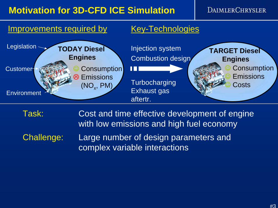
☺ Consumption Emissions(NOx, PM)
TODAY Diesel Engines
Task: Cost and time effective development of engine with low emissions and high fuel economy
Key-Technologies
Injection systemCombustion design
TurbochargingExhaust gas aftertr.
Challenge: Large number of design parameters andcomplex variable interactions
Legislation
Customer
Environment
Improvements required by
TARGET Diesel Engines☺ Consumption ☺ Emissions☺ Costs
Motivation for 3D-CFD ICE Simulation
#4
Motivation for 3D-CFD ICE Simulation
General Modeling Aspects
Demands on an Industrial CFD Code
Combustion Modeling Concepts at DCSpray Modeling
Combustion Modeling Validation
Conclusion
Outline
#5
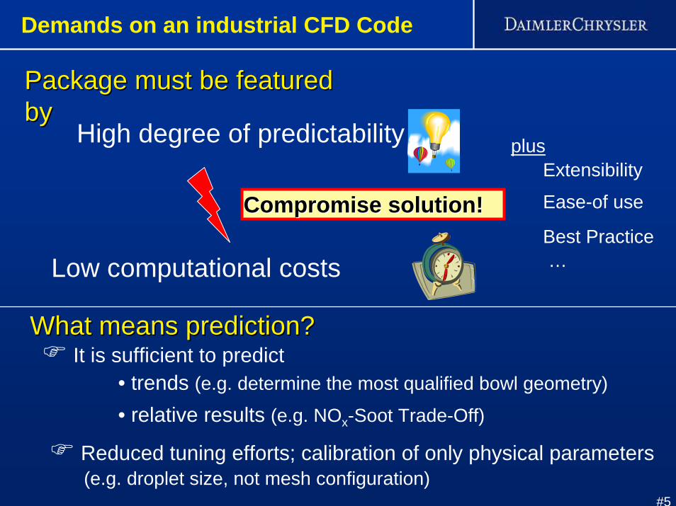
Compromise solution!Compromise solution!
Package must be featured Package must be featured byby
High degree of predictability
Low computational costs
ExtensibilityEase-of use
…Best Practice
plus
What means prediction?What means prediction?
• trends (e.g. determine the most qualified bowl geometry)
• relative results (e.g. NOx-Soot Trade-Off)
It is sufficient to predict
Reduced tuning efforts; calibration of only physical parameters(e.g. droplet size, not mesh configuration)
Demands on an industrial CFD Code
#6
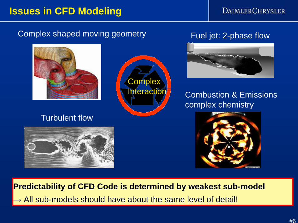
Turbulent flow
Fuel jet: 2-phase flowComplex shaped moving geometry
Combustion & Emissionscomplex chemistry
Predictability of CFD Code is determined by weakest subPredictability of CFD Code is determined by weakest sub--modelmodel→→ All subAll sub--models should have about the same level of detail!models should have about the same level of detail!
ComplexInteraction
Issues in CFD Modeling
#7
Motivation for 3D-CFD ICE Simulation
General Modeling Aspects
Demands on an Industrial CFD Code
Combustion Modeling Concepts at DCSpray Modeling
Combustion Modeling Validation
Conclusion
Outline
#8
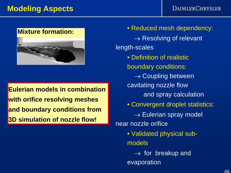
• Reduced mesh dependency:→ Resolving of relevant
length-scales • Definition of realistic boundary conditions:
→ Coupling between cavitating nozzle flow
and spray calculation• Convergent droplet statistics:→ Eulerian spray model
near nozzle orifice • Validated physical sub-models
→ for breakup and evaporation
Eulerian models in combination with orifice resolving meshesand boundary conditions from 3D simulation of nozzle flow!
Modeling Aspects
Mixture formation:

#9
Modeling Aspects
• Conventional Diesel ignition:→ Consideration of detailed chemistry
• Advanced combustion ignition, e.g. HCCI ignition: → Consideration of detailed chemistry in
low temperature range→ Description of multi-stage ignition (Cool Flame)
• Premixed combustion:→ Accounting for complex chemistry schemes
•Turbulence-chemistry interaction:→ Consideration of heterogeneous mixture fields→ Consideration of turbulent transport processes
Incorporation of validated detailed kinetics andaccounting for turbulence interaction!
Combustion
#10
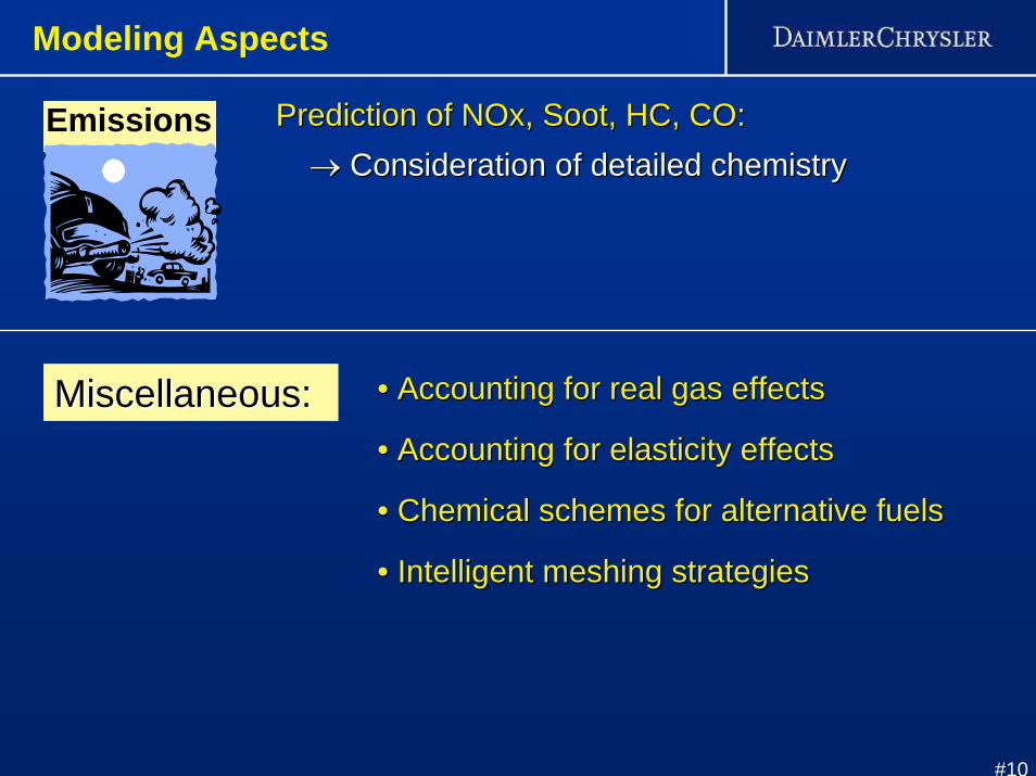
Emissions Prediction of Prediction of NOxNOx, Soot, HC, CO:, Soot, HC, CO:→→ Consideration of detailed chemistry Consideration of detailed chemistry
Miscellaneous:Miscellaneous: •• Accounting for real gas effectsAccounting for real gas effects
•• Accounting for elasticity effectsAccounting for elasticity effects
•• Chemical schemes for alternative fuels Chemical schemes for alternative fuels
•• Intelligent meshing strategiesIntelligent meshing strategies
Modeling Aspects
#11
Motivation for 3D-CFD ICE Simulation
General Modeling Aspects
Demands on an Industrial CFD Code
Combustion Modeling Concepts at DCSpray Modeling
Combustion Modeling Validation
Conclusion
Outline

#12
DC Approach for Spray
1. Resolution of relevant scales (hole diameter!) → spray adaptive meshCrucial for predictive spray simulations are:
Stochasticspray model
Coarse mesh Fine mesh
Eulerian-spray Model
⇒ Number of droplet classesindependent of cell size
Coarse mesh
“parcels”
Influence of mesh refinement on statistic
⇒ decrease of “parcels” per ce
Fine mesh
2. Capture of droplet statistics → Eulerian spray model in near nozzle region
Experiment
Simulation
ca. 1 mm
3. Boundary settings → Coupling between models for nozzle flow and spray4. Suitable models for spray breakup and droplet evaporation
#13
DC Approach for Spray
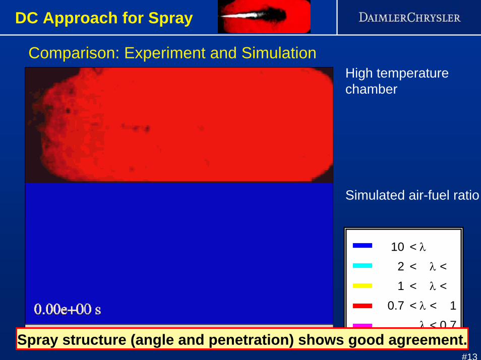
10 < λ
2 < λ <1 < λ <
0.7 < λ < 1λ < 0.7
Comparison: Experiment and SimulationHigh temperaturechamber
Simulated air-fuel ratio
Spray structure (angle and penetration) shows good agreement.
#14
Motivation for 3D-CFD ICE Simulation
General Modeling Aspects
Demands on an Industrial CFD Code
Combustion Modeling Concepts at DCSpray Modeling
Combustion Modeling Validation
Conclusion
Outline
#15
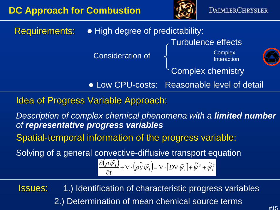
Requirements:Requirements: High degree of predictability:
Consideration ofTurbulence effects
Complex chemistryLow CPU-costs: Reasonable level of detail
Idea of Progress Variable Approach:Idea of Progress Variable Approach:Description of complex chemical phenomena with a limited numberof representative progress variablesSpatialSpatial--temporal information of the progress variable:temporal information of the progress variable:Solving of a general convective-diffusive transport equation
( ) ( ) [ ] ci
siii
i Dut
ψψψψρψρ ~~~~~~&&
r++∇⋅∇=⋅∇+
∂∂
DC Approach for Combustion
ComplexInteraction
Issues:Issues: 1.) Identification of characteristic progress variables2.) Determination of mean chemical source terms
#16
crank angle [°]BOI SI
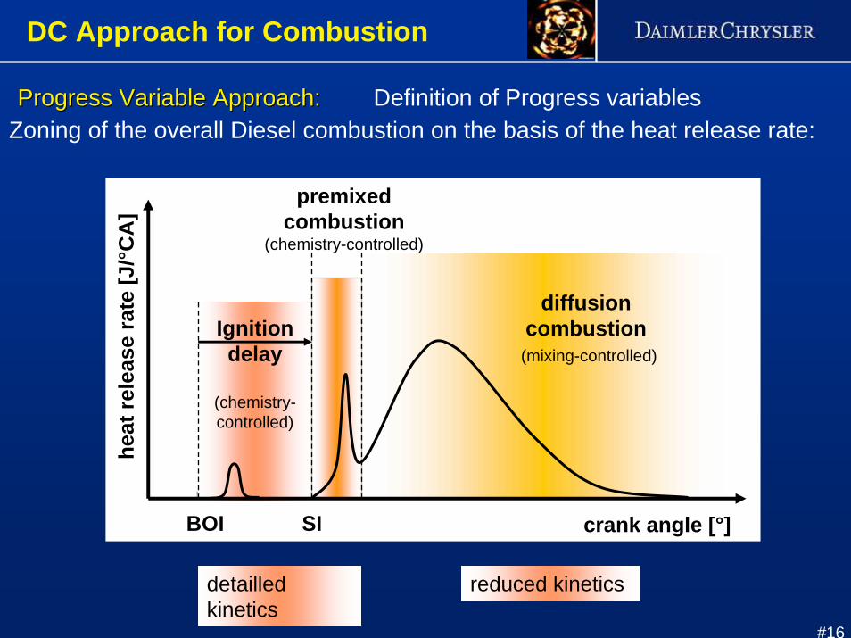
Progress Variable Approach:Progress Variable Approach: Definition of Progress variableshe
atre
leas
era
te [J
/°CA
]Zoning of the overall Diesel combustion on the basis of the heat release rate:
detailledkinetics
reduced kinetics
premixedcombustion
(chemistry-controlled)
Ignitiondelay
(chemistry-controlled)
diffusioncombustion
(mixing-controlled)
DC Approach for Combustion

#17
ProgressProgress--Approach:Approach: Determination of mean chemical sources terms
EngineCombustion
PDF-Type Model:- Numerical separation
Z0 1
PDF(Z)
Z0 1
w(Z)
Flamelet-Code
CFD-Code
Turbulent flowEnsemble-averaging:mean and variance
Probabilty densityfunction (PDF)
Chemical reactions(detailed kinetics)
C2H6 + O2 = C2H5 + HO2C2H6 + OH = C2H5 + H2OC2H6 + O = C2H5 + OH
. . .
∫ ⋅=Z
ii dZZPDFZ )()(ωω &
Mean source terms:
- PDF-Integration of“laminar” reaction rates
DC Approach for Combustion
#18
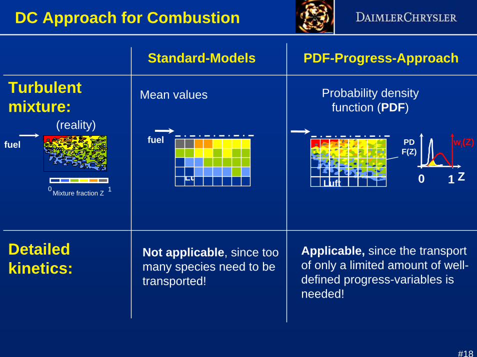
Turbulent mixture:
Standard-Models PDF-Progress-Approach
fuel
Mixture fraction Z0 1Luft
Mean values Probability density function (PDF)
(reality)
Luft Z0 1
PDF(Z)
wi(Z)fuel
Detailed kinetics:
Not applicable, since too many species need to betransported!
Applicable, since the transportof only a limited amount of well-defined progress-variables is needed!
DC Approach for Combustion
#19
Motivation for 3D-CFD ICE Simulation
General Modeling Aspects
Demands on an Industrial CFD Code
Combustion Modeling Concepts at DCSpray Modeling
Combustion Modeling Validation
Conclusion
Outline
#20
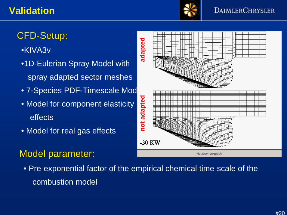
CFDCFD--Setup:Setup:•KIVA3v•1D-Eulerian Spray Model with
spray adapted sector meshes• 7-Species PDF-Timescale Model• Model for component elasticity
effects• Model for real gas effects
Model parameter:Model parameter:• Pre-exponential factor of the empirical chemical time-scale of the
combustion model
adap
ted
not a
dapt
ed
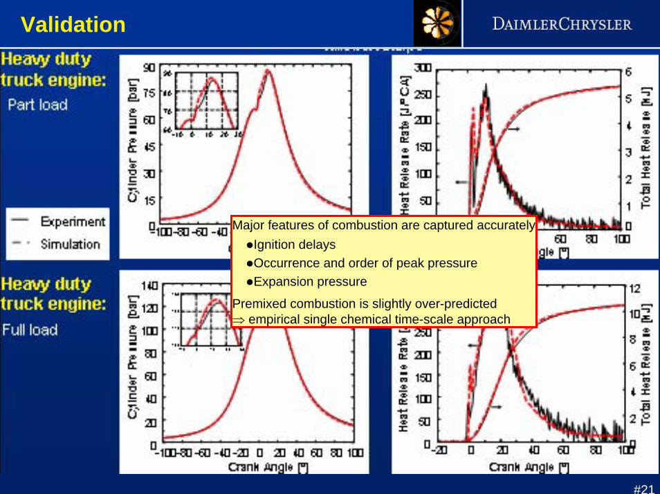
Validation
#21
Validation
Major features of combustion are captured accuratelyIgnition delaysOccurrence and order of peak pressureExpansion pressure
Premixed combustion is slightly over-predicted⇒ empirical single chemical time-scale approach
#22
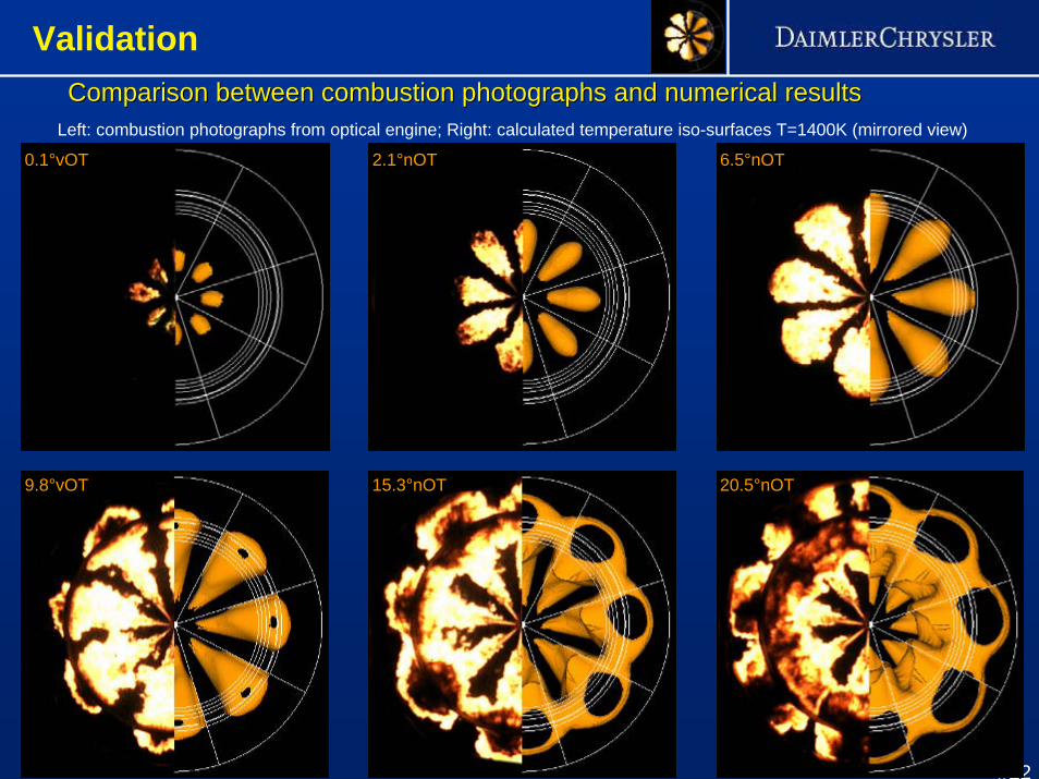
0.1°vOT 2.1°nOT 6.5°nOT
9.8°vOT 15.3°nOT 20.5°nOT
ComparisonComparison betweenbetween combustioncombustion photographsphotographs and and numericalnumerical resultsresultsLeft: combustion photographs from optical engine; Right: calculated temperature iso-surfaces T=1400K (mirrored view)
Validation

#23
Example of a local flow analysis for a marine engineExample of a local flow analysis for a marine engine
Validation

#24
Motivation for 3D-CFD ICE Simulation
General Modeling Aspects
Demands on an Industrial CFD Code
Combustion Modeling Concepts at DCSpray Modeling
Combustion Modeling Validation
Conclusion
Outline
#25
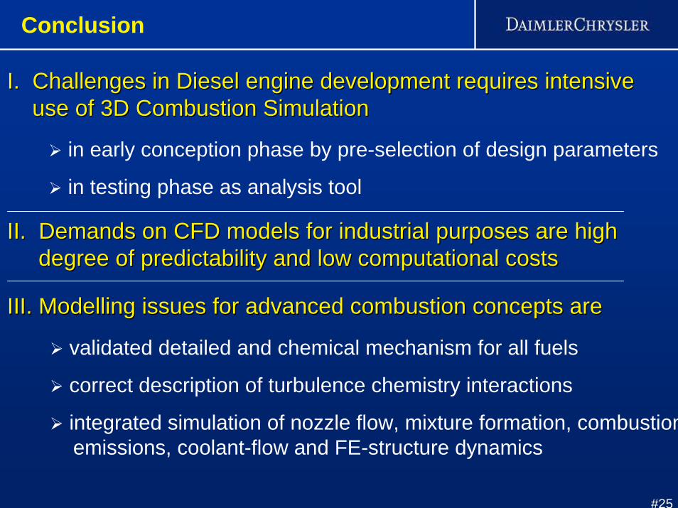
I. Challenges in Diesel engine development requires intensive I. Challenges in Diesel engine development requires intensive use of 3D Combustion Simulationuse of 3D Combustion Simulation
in early conception phase by pre-selection of design parameters
in testing phase as analysis tool
II. Demands on CFD models for industrial purposes are high II. Demands on CFD models for industrial purposes are high degree of predictability and low computational costsdegree of predictability and low computational costs
III. Modelling issues for advanced combustion concepts areIII. Modelling issues for advanced combustion concepts are
validated detailed and chemical mechanism for all fuels
correct description of turbulence chemistry interactions
integrated simulation of nozzle flow, mixture formation, combustionemissions, coolant-flow and FE-structure dynamics
Conclusion