3800/3900/3900p pulse oximeter - frank's hospital …€¦ · ge healthcare 3800/3900/3900p...
TRANSCRIPT

GE Healthcare
3800/3900/3900P Pulse OximeterWith/Without TruTrak®+
Technical Reference Manual


GE Healthcare
3800/3900/3900P Pulse OximeterWith/Without TruTrak®+
Technical Reference Manual
6050-0006-404March 2005

Important
Rx Only (USA)
Attention! Consult the accompanying instructions, including all safetyprecautions, before using or servicing this device.
Responsibility of the manufacturerThe safety, reliability, and performance of this device can be assured only under thefollowing conditions:
• Fittings, extensions, readjustments, changes, or repairs are carried out byauthorized personnel.
• The electrical installation complies with relevant standards and regulations.
• The device is used according to the accompanying operating instructions and isserviced and maintained in accordance with this manual.
Service and repairService and repair procedures must be performed by authorized service personnel.Repair this device or its parts only in accordance with instructions provided by themanufacturer. To order replacement parts or for assistance, contact an authorizedservice office. When shipping the monitor for repair, clean the monitor, allow it todry completely, and pack it for shipment in the original shipping container, ifpossible.
TrademarksDatex®, Ohmeda®, OxyTip®, TruTrak®, PerfTrak®, TeleOximetry®, and PIr™ are theproperty of GE Healthcare Finland Oy. All other product and company names are theproperty of their respective owners.
0537
GE Healthcare Finland OyHelsinki, Finland+358 10 394 11www.gehealthcare.com
© 2005 General Electric Company. All rights reserved.

Contents
i
1/OverviewRelated information..........................................................................................................1-1Technical competence.....................................................................................................1-1
1.1 General description...........................................................................................................................1-21.1.1 Major components, block interconnect diagram.............................................1-21.1.2 General subassembly description.............................................................................1-2
Power inlet module............................................................................................................1-2Power supply.........................................................................................................................1-3Battery......................................................................................................................................1-3System board........................................................................................................................1-3Oximetry board....................................................................................................................1-3Sensor filter board..............................................................................................................1-3Front panel .............................................................................................................................1-33900P printer .........................................................................................................................1-3
1.2 Compliance with standards .........................................................................................................1-41.2.1 General safety requirements ........................................................................................1-4
Safety checks for software.............................................................................................1-41.2.2 Electromagnetic compatibility (EMC) ......................................................................1-5
Electromagnetic effects ..................................................................................................1-8
1.3 Specifications.......................................................................................................................................1-91.3.1 General .....................................................................................................................................1-9
Circuitry ...................................................................................................................................1-9Displays ...................................................................................................................................1-9Audio indicators ..................................................................................................................1-9Dimensions and weight ...................................................................................................1-9
1.3.2 Factory settings................................................................................................................1-10Mode switches...................................................................................................................1-10
1.3.3 Measurement .....................................................................................................................1-11SpO2........................................................................................................................................1-11Pulse rate .............................................................................................................................1-11PIr pulsatile value...........................................................................................................1-11Interfering substances ..................................................................................................1-11Sensor emitter wavelength ranges.........................................................................1-11
1.3.4 Alarms....................................................................................................................................1-12Audible alarms..................................................................................................................1-12Alarm limits ........................................................................................................................1-12
1.3.5 Environmental...................................................................................................................1-121.3.6 Electrical...............................................................................................................................1-12
Power......................................................................................................................................1-12Current leakage................................................................................................................1-12Fuse.........................................................................................................................................1-12Battery...................................................................................................................................1-13
1.3.7 RS-232 connector .............................................................................................................1-13
1.4 Precautions ........................................................................................................................................1-141.4.1 Warnings..............................................................................................................................1-141.4.2 Cautions................................................................................................................................1-15
1.5 Safety guidelines.............................................................................................................................1-161.5.1 Cleaning................................................................................................................................1-16

Contents
i i
2/Theory of Operations2.1 Power supply and power inlet module...................................................................................2-1
2.2 System board .......................................................................................................................................2-2System board functions..................................................................................................2-2
2.2.1 System board data management..............................................................................2-2Microprocessor ....................................................................................................................2-3SRAM..........................................................................................................................................2-3Flash memory and software upgrade socket ......................................................2-3RS-232 connector interface ...........................................................................................2-3Mode switch...........................................................................................................................2-3Alarm signal and pulse tone generator ..................................................................2-3Microprocessor supervisor ............................................................................................2-3Audio amplifier ....................................................................................................................2-4Front panel interface........................................................................................................2-4Background debug ............................................................................................................2-4(3900/3900P) Real-time clock........................................................................................2-4(3900P) Printer interface ..................................................................................................2-4
2.2.2 System board power management ..........................................................................2-4+ 5 V supply ............................................................................................................................2-4Battery charger....................................................................................................................2-5Battery monitor ...................................................................................................................2-5AC monitor..............................................................................................................................2-5+ VR supply.............................................................................................................................2-5Power on/standby circuitry ..........................................................................................2-5
2.3 Switch board.........................................................................................................................................2-6
2.4 Oximetry board...................................................................................................................................2-72.4.1 Oximetry board power supply section....................................................................2-72.4.2 Oximetry board digital section...................................................................................2-7
Microprocessor ....................................................................................................................2-7Flash memory.......................................................................................................................2-7SRAM..........................................................................................................................................2-7DAC .............................................................................................................................................2-7Reset circuit ...........................................................................................................................2-7
2.4.3 Oximetry board analog section..................................................................................2-8Detector preamplifier .......................................................................................................2-8Interference detect .............................................................................................................2-9Multiplexed low-pass filter ............................................................................................2-9Test circuit ..............................................................................................................................2-9Ambient light subtraction .............................................................................................2-9Composite gain stage ......................................................................................................2-9Demultiplex and low-pass filter..................................................................................2-9High-pass filter and multiplex.....................................................................................2-9AC gain stage........................................................................................................................2-9Demultiplex low pass .......................................................................................................2-9Analog multiplexor and buffer .................................................................................2-10Multiplexor ..........................................................................................................................2-10LED drive ...............................................................................................................................2-11Sensor monitor..................................................................................................................2-11Sensor identification .....................................................................................................2-11
2.5 Passive filtering (sensor filter board or flex cable).........................................................2-11
2.6 3900P Printer interface.................................................................................................................2-12

Contents
i i i
2.6.1 Printer board......................................................................................................................2-12Motor driver ........................................................................................................................2-12Tachometer shaper.........................................................................................................2-12Head drivers........................................................................................................................2-12ESD protection...................................................................................................................2-12Temperature sensor/keypad decoder ..................................................................2-13
2.6.2 Printer button board......................................................................................................2-13
3/Test and Upgrade Procedures3.1 Functionality test ..............................................................................................................................3-1
3.1.1 Printer test (3900P) ..............................................................................................................3-33.1.2 Diagnostic self-test............................................................................................................3-4
3.2 Electrical safety check ....................................................................................................................3-4
3.3 Software upgrade...............................................................................................................................3-53.3.1 Remove the cover and identify the system board............................................3-63.3.2 (Optional) Check the installed software versions...............................................3-63.3.3 System software upgrade using the U-LOADER or LOADER chip...............3-73.3.4 System software upgrade using the SYS chip......................................................3-93.3.5 Oximetry software upgrade (monitors without TruTrak+) .........................3-113.3.6 Install the cover and check the installation.....................................................3-12
4/Troubleshooting4.1 Messages.................................................................................................................................................4-1
4.2 System failure error codes.............................................................................................................4-54.2.1 Nonfatal errors—the system continues running ...............................................4-54.2.2 Fatal errors—the system sounds an alarm tone and halts ..........................4-6
4.3 Troubleshooting guide....................................................................................................................4-8
4.4 3900/3900P TeleOximetry messages and troubleshooting.......................................4-124.4.1 TeleOximetry status messages.................................................................................4-124.4.2 TeleOximetry troubleshooting guide....................................................................4-14
4.5 Test points...........................................................................................................................................4-154.5.1 System board test points .............................................................................................4-154.5.2 Oximetry board test points ........................................................................................4-16
Oximetry board in TruTrak+ monitors .................................................................4-16Oximetry board in monitors without TruTrak+...............................................4-17
5/Repair and Replacement Procedures5.1 Oximeter cover.....................................................................................................................................5-2
5.1.1 Removing the cover...........................................................................................................5-25.1.2 Replacing the cover...........................................................................................................5-2
5.2 Front panel assembly......................................................................................................................5-35.2.1 Front panel, remove and disassemble ....................................................................5-35.2.2 Sensor filter replacement (board or flex cable) ...................................................5-4
Sensor filter board..............................................................................................................5-4Sensor filter flex cable ......................................................................................................5-4
5.2.3 Sensor connector replacement...................................................................................5-45.2.4 Switch board LCD replacement...................................................................................5-45.2.5 Button pad replacement.................................................................................................5-4

Contents
iv
5.2.6 Switch board replacement ............................................................................................5-55.2.7 Front panel, reassemble and reinstall .....................................................................5-5
5.3 Power-related components..........................................................................................................5-75.3.1 Power supply replacement............................................................................................5-75.3.2 Equipotential ground connector replacement...................................................5-75.3.3 Power inlet module replacement...............................................................................5-85.3.4 Fuse replacement ...............................................................................................................5-95.3.5 Battery replacement ......................................................................................................5-10
5.4 Speaker replacement ....................................................................................................................5-11
5.5 System board replacement .......................................................................................................5-12
5.6 Oximetry board replacement...................................................................................................5-14
5.7 3900P Printer repair........................................................................................................................5-155.7.1 Printer board replacement .........................................................................................5-155.7.2 Printer button board replacement.........................................................................5-15
6/Illustrated Parts6.1 Service kits .............................................................................................................................................6-2
6.2 Front panel assembly......................................................................................................................6-66.2.1 Front panel components ................................................................................................6-66.2.2 Front panel assembly drawing (3800) ......................................................................6-76.2.3 Front panel assembly drawing (3900/3900P)........................................................6-8
6.3 Chassis assembly...............................................................................................................................6-96.3.1 Chassis components .........................................................................................................6-96.3.2 Chassis assembly drawing .........................................................................................6-10
6.4 Printer/cover assembly (3900P)................................................................................................6-116.4.1 Printer/cover components..........................................................................................6-116.4.2 Printer/cover assembly drawing.............................................................................6-12
6.5 System board ....................................................................................................................................6-136.5.1 System board components shown.........................................................................6-136.5.2 System board layout (all monitors except 3800 without TruTrak+) .....6-136.5.3 System board layout (3800 REF 6051-0000-064 and 6051-0000-163) .....6-14
6.6 Oximetry board................................................................................................................................6-156.6.1 Oximetry board layout (TruTrak+ monitors) .....................................................6-156.6.2 Oximetry board layout (monitors without TruTrak+)...................................6-16
6.7 Switch board......................................................................................................................................6-17
6.8 Sensor filter flex cable (TruTrak+ monitors).......................................................................6-18
6.9 Sensor filter board (monitors without TruTrak+) ............................................................6-18
6.9 3900P Printer boards .....................................................................................................................6-196.9.1 3900P Printer board........................................................................................................6-196.9.2 3900P Printer button board........................................................................................6-19

1-1
1/OverviewThis manual provides instructions for servicing all Model 3800, Model 3900, and Model3900P pulse oximeters. This includes models with TruTrak®+ technology, the patentedtechnology for enhanced performance during conditions of clinical patient motion.
Important: Only OxyTip®+ sensors can be used with TruTrak+ monitors.
The 3900P is identical to the 3900, except that it contains an integral printer. Allreferences to printer functions and components are for the 3900P only.
This chapter contains:
• A general description of the oximeter and its main components.
• Oximeter specifications.
• Precautions, including specific warnings and cautions you must follow whenservicing the oximeter.
• Safety procedures you must follow when handling or repairing equipment thatmay be contaminated.
Related informationFor a detailed description of your monitor’s components, functions, general operatingguidelines, and RS-232 interface, see the 3900/3900P Pulse Oximeter User’s Manual orthe 3800 Pulse Oximeter User’s Manual.
If you need to reference printed circuit board schematics and component lists,purchase and refer to the information contained in the 3800/3900/3900P PCA DrawingsService Kit. See chapter 6 for a description and order number.
For information related to sensors (sensor application and cleaning, for example), referto the instructions for the sensor.
Technical competence
CAUTION: Only qualified service personnel should perform the procedures described inthis manual.
Only trained service personnel or competent individuals who are experienced withservicing medical devices of this nature should perform the procedures described inthis service manual.

3800/3900/3900P Technical Reference Manual
1-2
1.1 General descriptionThe 3800, 3900, and 3900P pulse oximeters are noninvasive, arterial oxygen saturationand pulse rate monitors. Through the use of a sensor applied to the patient andconnected to the monitor, these pulse oximeters measure the absorption of selectedwavelengths of light to calculate pulse rate and arterial oxygen saturation. The lightgenerated in the sensor passes through the tissue and is converted into an electronicsignal by a photodetector in the sensor. The electronic signal passes to the oximeterand is amplified. Analog and digital signal processing convert the light intensityinformation into SpO2 and pulse rate values.
Both models feature two easy-to-read displays that present patient data and statusinformation.
• The numeric LEDs (light-emitting diodes) show the SpO2 and pulse rate values.
• The LCD (liquid crystal display) shows alarm messages, the plethysmographicwaveform (or data), and the high and low SpO2 and pulse rate limit settings. Thisdisplay also shows the Relative Perfusion Index (PIr®) pulsatile value and menusas appropriate for the monitor.
1.1.1 Major components, block interconnect diagram
Power inletmodule
Mode switches
RS-232 port
Battery
Front panel
Sensor filterboard
ACPower
Oximetrysensor
Power supply +12 V
System board
3900PPrinter board
3900P Printerbutton board
Oximetry board
1.1.2 General subassembly descriptionThe descriptions that follow discuss the interaction of major components within thepulse oximeter. More detailed information for each component is found in chapter 2.
Power inlet moduleThe primary function of the power inlet module is to allow the oximeter to beconnected to an AC power source. It also serves as a filter for electromagneticcompatibility (EMC) compliance and contains fuses to limit the current flow. Thismodule is connected to the power supply.

1/Overview
1-3
Power supplyThe power supply converts power from any AC source between 90 and 264 VAC at47 to 63 Hz to +12 VDC. It also provides the necessary isolation between the patientand the mains. The +12 VDC is connected to the system board for further conditioning.
BatteryPower for the unit, when it is not connected to the AC mains power, is supplied by thebattery. The nominal battery voltage is 8 V. The battery is connected to the systemboard, which conditions the battery and charges the battery when the unit isconnected to the AC mains power.
System boardThis board conditions power from the +12 V power supply and the battery. It chargesthe battery when supplied with a DC voltage from the power supply. On power up itreads the position of the mode switches on the back panel. It communicates throughthe RS-232 port. The board sends data to the front panel for display and monitors thebutton switches. An upgrade socket on the board provides a means of upgrading thesoftware. The board monitors and sends commands to the oximetry board via a serialinterface and a few discrete digital lines.
The board communicates printer functions to the 3900P printer board. It also containsa real-time clock for use in 3900/3900P monitors.
Oximetry boardThis board drives the LEDs in the oximetry sensor and receives the photodetectorsignals. The signals pass through the sensor filter board. The photodetector signal isconditioned and processed on the oximetry board and the output is used to determinepatient oxygen saturation, perfusion, and pulse rate. The output is sent to the systemboard.
Sensor filter boardThis board filters out unwanted electrical signals (EMC, surges, noise, etc.). These areinternal signals that should not leave the unit and external signals that should notenter the unit.
Front panelThis panel displays information sent to it by the system board: saturation, pulse rate,plethysmographic waveform, alarm messages, and alarm indicators. The panel alsocontains the primary user-interface switches. It displays the AC power status andcontains the power/standby switch.
3900P printerThe printer board and printer button board interface to the system board. The systemboard controls the 3900P printer to provide printed output of current monitoring data,stored trend, and summary data.

3800/3900/3900P Technical Reference Manual
1-4
1.2 Compliance with standardsCompliance with standards The presence on the monitor of any symbol describedbelow indicates compliance with the standard represented by that symbol.
0537
Medical Device Directive 93/42/EEC of the European Union for a class I(with a measuring function), IIa, IIb, or III device.
Medical electrical equipment classified in the US and Canada withrespect to electric shock, fire, and mechanical hazards only, inaccordance with the Canadian Standards Association CAN/CSA C22.2 No.601.1 and Underwriters Laboratories Inc. UL 2601-1.
Medical electrical equipment classified with respect to electric shock,fire, and mechanical hazards only, in accordance with the CanadianStandards Association CAN/CSA C22.2 No. 601.1.
Medical electrical equipment classified with respect to electric shock,fire, and mechanical hazards only, in accordance with UnderwritersLaboratories Inc. UL 2601-1.
1.2.1 General safety requirementsThe 3800, 3900, and 3900P pulse oximeters comply with the requirements of EN 60601-1 Part 1: General requirements for safety of medical electrical equipment.
Type BF applied part.
Type of protection against electric shock: Class I/Internal electrical power source
Degree of protection against ingress of liquids: Ordinary (IPX0)
Mode of operation: Continuous
The oximeter also complies with the following:
EN 865 Pulse oximeters – Particular requirements
EN 475 Medical devices – Electrical ly-generated alarm signals.
Safety checks for softwareSoftware design controls include performance of a risk analysis using methodsconsistent with EN 1441 Medical devices – Risk analysis.
To ensure proper operation of the software, the monitor employs three separatewatchdog circuits for the microprocessors, power-on self-tests (including memorychecksum and calibration verification), and memory tests during monitoring. Thesoftware continuously monitors the patient sensor and, if a failure is detected,discontinues power to the sensor.

1/Overview
1-5
1.2.2 Electromagnetic compatibility (EMC)The 3800, 3900, and 3900P pulse oximeters comply with the requirements of EN 60601-1-2: Electromagnetic compatibility - Requirements and tests.
Emissions EN 55011 Group I, Class B
The 3800, 3900, and 3900P oximeters were tested with no peripheral devices whenoperating on battery power.
The 3800 pulse oximeter was tested with an RS-232 cable attached when operating onAC power.
The 3900 and 3900P pulse oximeters were tested with an RS-232 cable and analogoutput cables attached when operating on AC power. A USRobotics Sportster FaxModem was connected to the 3900 when Electrical Safety and EMC testing wasperformed. The analog output was measured using a fiber optic link during testing.
When installing and using this monitor, take precautions to ensure electromagneticcompatibility.
Table 1-1. Guidance and manufacturer’s declaration - electromagnetic emissions
The 3800/3900/3900P TruTrak+ is suitable for use in the electromagnetic environment specified below. The customeror the user of the 3800/3900/3900P TruTrak+ should assure that it is used in such an environment.
Emissions test Compliance Electromagnetic environment - guidance
RF emissions
CISPR 11Group 1
The 3800/3900/3900P TruTrak+ uses RF energy only for itsinternal function. Therefore, its RF emissions are very lowand are not likely to cause any interference in nearbyelectronic equipment.
RF emissions
CISPR 11Class B
Harmonic emissions
IEC 61000-3-2Class A
Voltage fluctuations/flicker emissions
IEC 61000-3-3Complies
The 3800/3900/3900P TruTrak+ is suitable for use in allestablishments, including domestic establishments andthose directly connected to the public low-voltage powersupply network that supplies buildings used for domesticpurposes.

3800/3900/3900P Technical Reference Manual
1-6
Table 1-2 Guidance and manufacturer’s declaration - electromagnetic immunity
The 3800/3900/3900P TruTrak+ is intended for use in the electromagnetic environment specified below. The customeror the user of the 3800/3900/3900P TruTrak+ should assure that it is used in such an environment:
Immunity test IEC 60601-1-2 test level Compliance level Electromagnetic environment -guidance
Electrostaticdischarge (ESD)
IEC 61000-4-2
± 6 kV contact
± 8 kV air
± 6 kV contact
± 8 kV air
Floors should be wood,concrete, or ceramic tile. Iffloors are covered withsynthetic material, the relativehumidity should be at least30%.
Electrical fasttransient/burst
IEC 61000-4-4
± 2 kV for power supply lines
± 1 kV for input/output lines
± 2 kV for power supply lines
± 1 kV for input/output lines
Mains power quality should bethat of a typical commercial orhospital env i ronment
Surge
IEC 61000-4-5
± 1 kV differential mode
± 2 kV common mode
± 1 kV differential mode
± 2 kV common mode
Mains power quality should bethat of a typical commercial orhospital env i ronment.
Voltage dips,shortinterruptionsand vol tagevariations onpower supplyinput lines
IEC 61000-4-11
< 5 % U T
(> 95 % dip in U T) for 0,5 cycle
40 % UT
(60 % dip in UT) for 5 cycles
70 % UT
(30 % dip in UT) for 25 cycles
< 5 % U T
(> 95 % dip in U T) for 5 sec
< 5 % U T
(> 95 % dip in U T) for 0,5 cycle
40 % UT
(60 % dip in UT) for 5 cycles
70 % UT
(30 % dip in UT) for 25 cycles
< 5 % U T
(> 95 % dip in U T) for 5 sec
Mains power quality should bethat of a typical commercial orhospital env i ronment. If theuser of the 3800/3900/3900PTruTrak+ requires continuedoperation during power mainsinterruptions, it isrecommended that the3800/3900/3900P TruTrak+ bepowered from anuninterrupt i ble power supplyor a battery.
Power frequency(50/60 Hz)magnetic field
IEC 61000-4-8
3 A/m 3 A/m Power frequency magnetic fieldsshould be at levelscharacteristic of a typ i callocation in a typical commercialor hospital environment.
NOTE: U T is the a.c. mains voltage prior to application of the test level.

1/Overview
1-7
Table 1-3 Guidance and manufacturer’s declaration - electromagnetic Immunity
The 3800/3900/3900P TruTrak+ is intended for use in the electromagnetic environment specified below. The customeror the user of the 3800/3900/3900P TruTrak+ should assure that it is used in such an environment:
Immunity test IEC 60601 test level Compliance level Electromagnetic environment - guidance
Conducted RFIEC 61000-4-6
Radiated RFIEC 61000-4-3
3 Vrms150 kHz to 80 MHz
3 V/m80 MHz to 2,5 GHz
5 V
5 V/m
Portable and mobile RF communications equipmentshould be used no closer to any part of the3800/3900/3900P TruTrak+, including cables, than therecommended separation distance calculated fromthe equation applicable for the frequency of thetransmitter.
Recommended Separation Distance
Pd = 0.70
Pd = 0.70 80 MHz to 800 MHz
Pd = 1.40 800 MHz to 2,5 GHz
where P is the maximum output power rat ing of thetransmitter in watts (W) according to the transmittermanufacturer and d is the recommended separationdis tance in meters (m).
Field strengths from fixed RF transmitters, as deter-mined by an electromagnetic site survey, a shouldbe less than the compliance level in each frequencyrange.b
Interference may occur in the vicinity of equipmentmarked with the following symbol:
NOTE 1: At 80 MHz and 800 MHz, the separation distance for the higher frequency range applies.
NOTE 2: These guidelines may not apply in all situations. Electromagnetic propagation is affected by absorptionand reflection from structures, objects, and people.
a Field strengths from fixed transmitters, such as base stations for radio (cellular/cordless) telephones and landmobile radios, amateur radio, AM and FM radio broadcast, and TV broadcast cannot be predicted theoreticallywith accuracy. To assess the electromagnetic environment due to fixed RF transmitters, an electromagnetic sitesurvey should be considered. If the measured field strength in the location in which the 3800/3900/3900P TruTrak+is used exceeds the applicable RF compliance level above, the 3800/3900/3900P TruTrak+ should be observed toverify normal operation. If abnormal performance is observed, additional measures may be necessary, such as re-orienting or relocating the 3800/3900/3900P TruTrak+.
b Over the frequency range 150 kHz to 80 MHz, field strengths should be less than 5 V/m.

3800/3900/3900P Technical Reference Manual
1-8
Electromagnetic effectsElectromagnetic interference, including interference from portable and mobile radiofrequency (RF) communications equipment, can affect this monitor.
Table 1-4 Recommended Separation Distances between Portable and Mobile RF CommunicationsEquipment and the 3800/3900/3900P TruTrak+
The 3800/3900/3900P TruTrak+ is intended for use in an electromagnetic environment in which RF disturbances arecontrolled. The customer or the user of the 3800/3900/3900P TruTrak+ can prevent electromagnetic interference bymaintaining a minimum distance between portable and mobile RF communications equipment (transmitters) andthe 3800/3900/3900P TruTrak+ as recommended below, according to the maximum output power of thecommunications equipment.
Separation distance according to the frequency of the transmitter
mRated maximum output
power of transmitter
W 150 kHz to 80 MHz
Pd = 0.7080 MHz to 800 MHz
Pd = 0.70800 MHz to 2,5 GHz
Pd = 1.40
0.01 0.07 0.07 0.14
0.1 0.22 0.22 0.44
1 0.70 0.70 1.40
10 2.2 2.2 4.4
100 7.0 7.0 14.0
For transmitters rated at a maximum output power not listed above, the recommended separation distance d inmeters (m) can be estimated using the equation applicable to the frequency of the transmitter, where P is themaximum output power rating of the transmitter in watts (W) according to the transmitter manufacturer.
NOTE 1: At 80 MHz and 800 MHz, the separation distance for the higher frequency range applies.
NOTE 2: These guidelines may not apply in all situations. Electromagnetic propagation is affected by absorptionand reflection from structures, objects, and people.
Indications that the monitor is experiencing electromagnetic interference include thefollowing:
• Variations in the PerfTrak waveform display.
• Sudden increases or decreases in the waveform height that do not correlate to thephysiological condition of the patient.
• Sensor-related messages that are not resolved by the instructions found in thismanual.
• The display of dashes on numeric LEDs when a valid physiological signal ispresent.
• (3900P ) Printed output that is garbled, solid black, or missing.
This interference may be intermittent and careful correlation between the effect and itspossible source is important. Indications of interference should not occur if themonitor is used within its intended electromagnetic environment.

1/Overview
1-9
1.3 SpecificationsUnless otherwise indicated, all specifications are nominal and are subject to changewithout notice.
1.3.1 GeneralCircuitry
Microprocessor-controlled
Automatic self-test of oximeter when powered on
Automatic setting of default parameters
Automatic alarm messages
(3800) Up to 12 hours of stored trend data output through the RS-232 serial port for SpO2,pulse rate, and alarm messages
(3900/3900P) Real-time data output or up to 24 hours of stored trend data outputthrough the RS-232 port for SpO2, pulse rate, PI r pulsatile value, and alarm messages;SpO2 and pulse rate output through two analog channels
DisplaysThe displayed SpO2, pulse rate, and PIr values are updated every second. Theplethysmographic waveform sweep is updated every 4 seconds.
Numeric display (Light Emitting Diodes—LEDs)Arterial oxygen saturation (SpO2) reading
Pulse rate reading
Graphic display (Liquid Crystal Display—LCD)Plethysmographic waveform
High and low SpO2 and pulse rate alarm limits settings
Sensor condition alarms
Messages—alarm messages and system operational status messages
Contrast adjustment
(All monitors except 3800 without TruTrak+) PI r pulsatile value
(3900/3900P) SpO2 real-time or stored data graph
(3900/3900P) PI r pulsatile value real-time or stored data graph
Audio indicatorsAdjustable-volume pulse beep; pitch modulation reflects changing SpO2 levels
Adjustable-volume alarm tone
Alarm silence (120 seconds); all mute (continuous silence)
Out-of-limits alarms for SpO2 and pulse rate
Sensor-condition, system-failure, and recharge-battery alarms
Dimensions and weight(3800/3900) height x width x depth: 9.4 cm (3.7 in) x 24.4 cm (9.5 in) x 22.5 cm (8.9 in)
(3900P) height x width x depth: 10.4 cm (4.1 in) x 24.4 cm (9.5 in) x 22.5 cm (8.9 in)
Weight: 3800/3900—2.9 kg (6.5 lbs); 3900P—3.2 kg (7.0 lbs)

3800/3900/3900P Technical Reference Manual
1-10
1.3.2 Factory settings
Parameter 3900/3900P 3800
High SpO2 limit OFF (appears as – – –) OFF (appears as – – –)
Low SpO2 limit 85% 85%
High pulse rate 130 bpm Adult mode: 130 bpmNeonate mode: 200 bpm
Low pulse rate 40 bpm Adult mode: 40 bpmNeonate mode: 100 bpm
Alarm volume 3 3
Pulse volume 2 2
Save limits No Not applicable
Data output mode(printer and modem)
SpO2 Not applicable
Data output resolution 6-second Not applicable
All mute Yes Not applicable
Serial transmissionbaud rate
9600 Not applicable
Analog 0.0 V Not applicable
Print contrast 5 Not applicable
Date format DD/MM/YY Not applicable
Time format HH MM Not applicable
Mode switches
Switch 3900/3900P options 3800 options
Language Danish, Dutch, English(factory setting), Finnish,French, German, Italian,Japanese, Norwegian,Portuguese, Polish,Spanish, and Swedish
English (factory setting),French, German, Italian,Japanese, Portuguese,Spanish, and Swedish
Averaging mode Long / TruTrak+ (12 sec.factory setting), Medium(6 sec.), and Short (3 sec.)
Long / TruTrak+ (12 sec.factory setting), Medium(6 sec.), and Short (3 sec.)
Patient mode Not applicable Adult (factory setting) andNeonate
(TruTrak+ monitors) PI rpulsatile value display
Yes (factory setting) and No Yes (factory setting) and No
(Monitors without TruTrak+)SpO2 calibration
Fractional (factory setting)and functional
Fractional (factory setting)and functional
EMI line frequency 60 Hz 60 Hz

1/Overview
1-11
1.3.3 MeasurementSpO2 TruTrak+ monitors Monitors without TruTrak+
Calibration Functional Fractional or Functional
Range 0 to 100% 0 to 100%
Accuracy, Arms(previouslyrepresentedby 1 SD)
70 to 100% ± 2 digits
70 to 100% ± 3 digits duringconditions of clinical patientmotion (with TruTrak+ enabled)
Below 70% unspecified
Accuracy, 1 SD 80 to 100% ± 2%
60 to 79% ± 3%
Below 60% unspecified
Resolution 1% 1%
Pulse rate TruTrak+ monitors Monitors without TruTrak+
Range 30 to 250 bpm 20 to 255 bpm
Accuracy(assuming aconstantpulse rate)
± 2% or ± 2 bpm (whichever isgreater)
Accuracy during conditions ofclinical patient motion:unspecified
40 to 235 bpm ± 1.7% ofreading
Resolution 1 bpm 1 bpm
PIr pulsatile valueTruTrak+ monitors
and 3900/3900P withoutTruTrak+
3800 without TruTrak+
Range 0.00 to 9.99 Not applicable
Averaginginterval
12 seconds Not applicable
Resolution 0.01 Not applicable
Interfering substancesCarboxyhemoglobin may erroneously increase readings. The level of increase isapproximately equal to the amount of carboxyhemoglobin present. Dyes, or anysubstances containing dyes, that change usual arterial pigmentation may causeerroneous readings.
Sensor emitter wavelength rangesRed LED peak wavelength range: 650 to 670 nmInfrared (IR) LED peak wavelength range: 930 to 950 nmAverage power: ≤ 1 mW

3800/3900/3900P Technical Reference Manual
1-12
1.3.4 AlarmsAudible alarms
Setting levels available:Alarm: 1 through 5Pulse beep: OFF and 1 through 5
Volume intensity at 1-meter distance:Setting of 1: 45 decibels (minimum)Setting of 5: 85 decibels (maximum)
Alarm limitsSpO2 alarm limit range:
High = 50 to 100%, or OFFLow = OFF, or 50 to 100%
Pulse rate alarm limit range in beats per minute (bpm):
TruTrak+ monitors Monitors without TruTrak+High = 30 to 235, or OFFLow = OFF, or 30 to 235
High = 40 to 235, or OFFLow = OFF, or 40 to 235
1.3.5 EnvironmentalParameter Operating Transport and Storage
Temperature 0 to 50 ºC (32 to 122 ºF) –40 to 70 ºC (–40 to 158 ºF)
3900P with printer paper:–20 to 45 °C (4 to 113 °F)
Relative humidity,noncondensing
20% to 95% 5% to 95%
Pressure 1060 to 697 hPa 1060 to 188 hPa
Approximateelevation
–378 to 3048 m(–1240 to 10,000 ft.)
–378 to 12.2 km(–1240 to 40,000 ft.)
1.3.6 ElectricalPower
Consumption (typical): 15 watts (3900P—20 watts)
Input voltage range: 90 to 264 VAC at 47-63 Hz
Current (typical): 0.45 Arms at 100 V, 0.37 Arms at 120 V, 0.25 Arms at 220/230/240 V
Current leakageWith power on, forward or reverse polarity: 100 microamperes maximum
Ground resistance: less than 0.1 Ω
FuseT2.0AH/250V, 5mm (OD) x 20 mm (Length)
1/Overview
1-13
BatteryType: 8 volt, sealed lead-acid
Capacity: 3.2 ampere hours
Operation time for a new battery at normal operating temperatures:At least 5 1/2 hours (with all functions operative from a fully charged battery).3900P—approximately 4 hours when printing.
Low battery indicator (LOW BATTERY): indicates the remaining battery capacity isbetween 5 and 15 minutes.
Important: To prevent permanent damage to the battery, recharge a dischargedbattery within eight hours after LOW BATTERY is displayed.
Charge time:4 hours = 80% capacity8 hours = 100% capacity
Life: several hundred charge/discharge cycles
Shelf life: 6 months (maximum if not recharged) when stored at room temperature;batteries stored for extended periods of time should be recharged every six monthsto maintain the charging capacity.
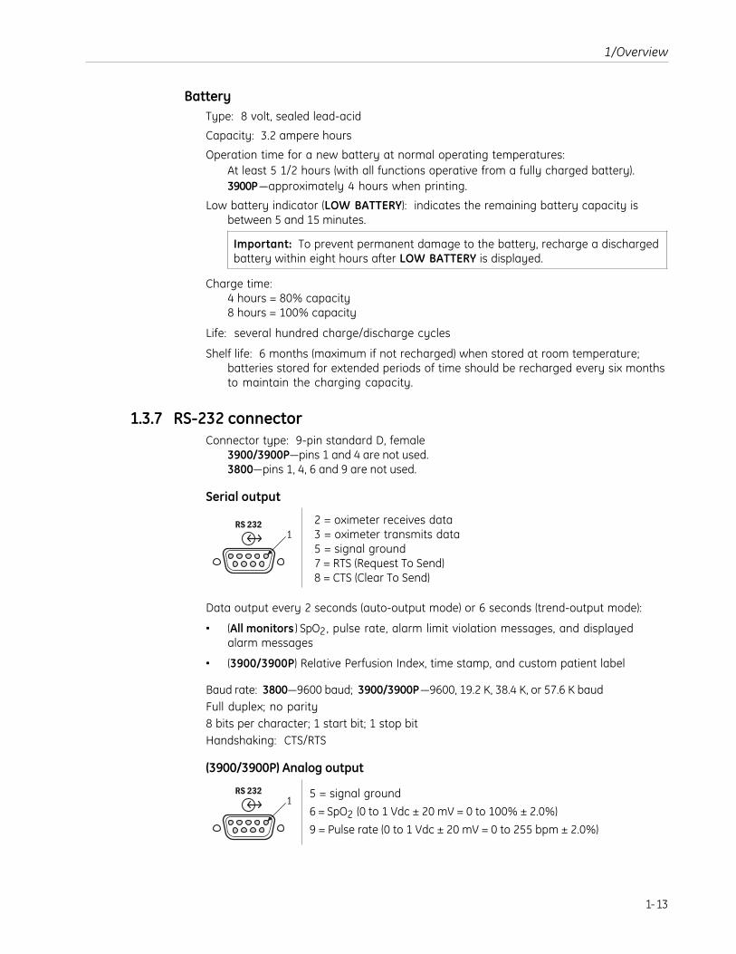
1.3.7 RS-232 connectorConnector type: 9-pin standard D, female
3900/3900P—pins 1 and 4 are not used.3800—pins 1, 4, 6 and 9 are not used.
Serial output
RS 2321
2 = oximeter receives data3 = oximeter transmits data5 = signal ground7 = RTS (Request To Send)8 = CTS (Clear To Send)
Data output every 2 seconds (auto-output mode) or 6 seconds (trend-output mode):
• (All monitors ) SpO2, pulse rate, alarm limit violation messages, and displayedalarm messages
• (3900/3900P) Relative Perfusion Index, time stamp, and custom patient label
Baud rate: 3800—9600 baud; 3900/3900P—9600, 19.2 K, 38.4 K, or 57.6 K baudFull duplex; no parity8 bits per character; 1 start bit; 1 stop bitHandshaking: CTS/RTS
(3900/3900P) Analog output
RS 2321
5 = signal ground
6 = SpO2 (0 to 1 Vdc ± 20 mV = 0 to 100% ± 2.0%)
9 = Pulse rate (0 to 1 Vdc ± 20 mV = 0 to 255 bpm ± 2.0%)

3800/3900/3900P Technical Reference Manual
1-14
1.4 PrecautionsTwo types of precautions appear in this manual: Warnings and cautions.
• A WARNING indicates the possibility of injury to the patient or operator.
• A CAUTION indicates a condition that may cause equipment damage ormalfunction.
(3900/3900P) If you connect a modem, refer to the precautions contained in theinstructions that accompanied your modem.
1.4.1 WarningsBattery replacement
To ensure proper operation, replace only with the recommended battery.
Failure of operationIf the oximeter fails any part of the checkout procedures or current leakage test,remove it from operation until qualified service personnel have corrected the situation.
Data validityConditions that may cause inaccurate readings and impact alarms include interferingsubstances, excessive ambient light, electrical interference, excessive motion, lowperfusion, low signal strength, incorrect sensor placement, poor sensor fit, andmovement of the sensor on the patient.
To prevent erroneous readings, do not use an inflated blood pressure cuff or arterialblood pressure measurement device on the same limb as the oximeter sensor.
Electrical shock hazardMeasure the oximeter’s leakage current in accordance with applicable standards aftercompleting any repair procedure.
This equipment must be properly grounded.
• Electrical safety specifications (e.g., current leakage and ground resistance) can beassured only when the oximeter is connected to a three-wire, grounded, receptaclewithout the use of extension cords or adapters.
• If there is any doubt about the integrity of the AC power supply protective earthconductor, operate the oximeter on internal battery power.
• Because the unit is not grounded when it is operating on battery power, do notconnect any equipment to the RS-232 port on the rear panel unless the unit isconnected to the AC power supply.
Before cleaning or repairing the monitor, turn it off and disconnect it from AC mainspower.
Fire/explosion hazardReplace fuses only with fuses of the same type and voltage rating.
Do not use the monitor in the presence of any flammable anesthetic mixture.

1/Overview
1-15
Patient safetyNever test or perform maintenance on the oximeter while it is being used to monitor apatient.
SensorsTo prevent injury or equipment damage, use only oximeter sensors approved for usewith this oximeter. For complete information about the safe and appropriate use of asensor, consult the instructions for that sensor.
Discard a damaged sensor immediately. Do not repair a damaged sensor or use asensor repaired by others.
1.4.2 CautionsGeneral
US Federal law restricts this device to sale by or on the order of a licensed medicalpractitioner.
Only qualified service personnel should perform the procedures described in thismanual.
Handle the monitor with care. Improper handling can cause damage or inaccurateresults.
Static sensitivityInternal electronic components are susceptible to damage by electrostatic discharge.To avoid damage when disassembling the oximeter, observe the standard precautionsand procedures for handling static-sensitive components.
(3900P ) To avoid damage to the print head from electrostatic discharge, take specialcare when servicing the 3900P printer.
SensorsDo not apply tension to the sensor cable; sensor damage may result.
CleaningDo not autoclave, pressure sterilize, or gas sterilize this oximeter.
Use cleaning solution sparingly. Do not soak or immerse the oximeter in liquid.Excessive solution can flow into the oximeter and damage internal components.
When cleaning the display area, do not use abrasive cleaning compounds or othermaterials that could damage the screen.
Do not use petroleum-based solutions, acetone solutions, or other harsh solvents toclean the oximeter. These substances may damage the oximeter and cause amalfunction.
(3900P ) Do not allow cleaning solution to get into the printer mechanism.
DisposalDispose of this medical device and its packaging according to local requirements.
Dispose of the battery, which contains lead and acid, through an approved hazardousmaterials disposal facility.

3800/3900/3900P Technical Reference Manual
1-16
1.5 Safety guidelinesBefore you start any procedure that involves disassembly of the oximeter, review theseguidelines to ensure the proper and safe completion of the procedure.
WARNING: Patient safety. Never test or perform maintenance on the oximeter while itis being used to monitor a patient.
WARNING: Electrical shock hazard. Before cleaning or repairing the monitor, turn it offand disconnect it from AC mains power.
1. Power off and disconnect the unit from the AC power supply.
2. Disconnect the sensor from the unit.
3. Clean the unit—see section 1.5.1.
4. Read and follow each step of all test and repair procedures. Give special attentionto all warnings and cautions.
Important: After repairs are complete, test the unit as directed at the end of eachprocedure to verify that it is functioning properly.
1.5.1 CleaningYou must clean the oximeter,• Before you start any procedure that involves disassembly of the oximeter.
• Before you send the oximeter for repair.
CAUTION: Cleaning• Do not autoclave, pressure sterilize, or gas sterilize the oximeter.
• Use cleaning solution sparingly. Do not soak or immerse the monitor in liquid.Excessive solution can flow into the monitor and damage internal components.
• When cleaning the display area, do not use abrasive cleaning compounds or othermaterials that could damage the screen.
• Do not use petroleum-based solutions, acetone solutions, or other harsh solventsto clean the oximeter. These substances may damage the oximeter and cause amalfunction.
• To prevent damage to the 3900P printer, do not allow cleaning solution to get intothe printer mechanism.
1. Turn off the oximeter and disconnect it from AC mains power.
2. Gently wipe the display panel with a cotton swab moistened with isopropylalcohol (70 vol%).
3. To clean the outer surface of the oximeter, use a soft cloth dampened with a mildsoap and water solution or one of the following solutions:
Mild detergent solution 0.5% sodium hypochlorite (bleach)
70% isopropyl alcohol Quarternary germicides (Virex®)
1.6% phenol (Sporicidin®) 3.4% glutaraldehyde (Cidex® Plus)

2-1
2/Theory of OperationsThis chapter covers the theory of operations for the following components:
• Power supply and power inlet module
• System board
• Switch board
• Oximetry board
• Passive filtering
• 3900P printer interface
2.1 Power supply and power inlet moduleThe power supply converts power from an AC power source to +12 VDC. It also providesthe necessary isolation between the patient and the AC power supply. It is connectedto the system board for further conditioning.
The power inlet module contains the three-contact power connector and the fuses.
Block diagram
Power inletmoduleTo AC power supply
Off-line switchingpower supply
12 VDCTo system board

3800/3900/3900P Technical Reference Manual
2-2
2.2 System boardThe system board has two major components:
• Data management section
• Power management section
System board functions• Condition power from the AC power supply and the battery.
• Charge the battery when supplied with a DC voltage from the power supply.
• Monitor language mode switch positions.
• Provide bi-directional communication through the RS-232 connector.
• Send data to the front panel for display.
• Monitor front panel button presses.
• Allow for software upgrades.
• Monitor and send commands to the oximetry board via a serial interface and a fewdiscrete digital lines.
• (3900/3900P) Send analog SpO2 and pulse rate data to analog outputs.
• (3900/3900P) Provide real-time clock capability.
• (3900P) Provide control for printer output.
2.2.1 System board data managementThe digital section of the system board provides data management. The digital sectioncontains the microprocessor, SRAM, Flash memory, a software upgrade socket, theRS-232 interface, mode switches, alarm signal generator, audio amplifier,microprocessor supervision, 3900/3900P real-time clock capability, and 3900P printerinterface.
Block diagram
Isolation
Microprocessorsupervisor
Mode switches
Backgrounddebug
Microprocessor
SpeakerTo oximetry board
To front panel
Upgrade socket
Flash memory
Static memory
Alarm tonegenerator Audio driver
RS-232 connector
(3900/3900P)Real-time clock
(3900P) To printer board

2/Theory of Operations
2-3
MicroprocessorThe microprocessor is a Motorola 68332 that operates at 16 MHz. It uses a crystal thatoperates at 32.768 KHz. Several ports can be configured by software. A 16-channel timerprocessing unit can be programmed to execute various timing functions, including aserial communication port. A background debug feature allows full access to theprocessor through a 10-pin connector. Communication to the oximetry board isaccomplished primarily through a dedicated serial port.
SRAMThe static RAM is 128 K x 8 bits. The SRAM is powered when the unit is in standby mode,which allows data to be retained when the digital system is powered down.
Flash memory and software upgrade socketThe Flash memory (512 K x 8 bits) contains the application code software, which runsthe oximeter. An upgrade socket allows download of revisions to the application codesoftware. The software upgrade socket accepts a memory chip with the same pinout asthe onboard Flash memory. A super cap provides flash memory backup while thebattery is disconnected.
RS-232 connector interfaceThis port, which operates at 9600 baud (3800) or 9600, 19.2K, 38.4K, or 57.6K baud(3900/3900P), allows for transmission of oximetry data to other serial devices. It hasoptoisolators and an isolated power supply so that there is no ohmic connectionbetween the connector and the digital system.
(3900/3900P) Two analog outputs allow SpO2 and pulse rate outputs in analog form, at0 to 1 volt full scale.
Mode switchThe mode switch settings determine the modes of operation for the oximeter, such asthe averaging mode, for example. The switches are ESD-protected by a 14-channel dualSCR chip connected to the power supply. The positions of the switches are read directlythrough 8 of the TPU channels.
Alarm signal and pulse tone generatorThis is a sawtooth generator. The circuit produces a signal that is rich in harmonics. Aresistor in the feedback loop controls the slope of the rising edge while another resistorcontrols the slope of the falling edge. The frequency is set to about 800 Hz. Volume iscontrolled by the microprocessor using pulse width modulation (PWM). Another PWMchannel on the microprocessor generates pulse tones; the microprocessor controls thefrequency of this tone. Discrete logic is incorporated to produce an alarm tone at fullvolume in the event that the microprocessor is not operating.
Microprocessor supervisorThis chip monitors the power supply, contains a watchdog, has battery switchovercircuitry, generates reset pulses, and disables the SRAM during power down. If thepower supply voltage is too low, this circuit holds the reset on the processor until thecorrect voltage is restored. It also switches the SRAM supply power to the Vbatt inputand disables RAM when the supply voltage is low. If the microprocessor does not pulsethe watchdog input occasionally, the chip issues a reset pulse. It also enables thealarm tones if the watchdog is active.

3800/3900/3900P Technical Reference Manual
2-4
Audio amplifierThis is a single chip that amplifies the audio tones. It has a bipolar output that allowsfor maximum volume with a single supply. The amplifier has a low-pass pole at 17.5KHz to reduce noise which may be picked up at the input to the amplifier.
Front panel interfaceSwitches on the front panel are read via various discrete I/O lines on the processor.They are scanned via an output port on the front panel circuit board (the switch board).The numeric displays on the front panel are sent data via the serial peripheral interfaceof the processor.
Background debugA 10-pin connector allows direct connection to the microprocessor. All microprocessorfunctions can be accessed through this interface.
Boot code and application code can be downloaded via this connector.
(3900/3900P) Real-time clockThis is a single chip connected to the microprocessor. It provides time, month, day, andyear for the display and for printed trend data. A super cap provides backup while thebattery is disconnected.
(3900P) Printer interfaceA connector and port allow the microprocessor to control printer functions.Handshaking lines synchronize the printer to the microprocessor. The microprocessordirectly controls the printhead patterns for text and graphic images.
2.2.2 System board power managementThe power management section generates + 5 V, switches between the + 12 V andbattery supplies, charges and monitors the battery voltage, and controls power on andstandby modes.
Block diagram
Memory
Switchover circuit
Front panel switch
Microprocessorsupervisor
AC monitor
Battery charger
Battery voltagemonitor
+ VR regulator
+ 5 V switchingregulator
Power on /standby control
+ 12 Vinput
Batteryinput
+ 5 V supply+ 5 V is generated by a buck-switching regulator that operates at 52 KHz. The inputvoltage is between about + 6.7 and + 12 V. This supplies power to the digital section, thefront panel, and the oximetry board.

2/Theory of Operations
2-5
Battery chargerThe battery charger is designed specifically for lead-acid batteries. If the batteryvoltage is less than 6.52 V, the circuit charges the battery at a low current. After thebattery reaches voltage 6.52 V, it charges the battery at 625 mA. When the batteryreaches 9.8 V, the charger changes to a constant voltage charger. When the chargingcurrent is less than 31 mA, the charger goes into a float state holding the batteryvoltage at 9.4 V.
Battery monitorThe battery is monitored for low voltage and recharge. The low voltage trip point is setat 7.3 V, and the recharge-battery-voltage trip point is set at 7.0 V. The low batterysignal is sent to the microprocessor. The recharge battery signal is latched withdiscrete logic. In the event that a recharge battery condition is reached, the unit mustbe connected to AC mains power to reset the recharge battery latch.
AC monitor+ 12 V is used to indicate that the unit is connected to AC mains power. This signal islevel shifted to + 5 V and sent to the processor.
+ VR supply+ VR is generated by a low power linear regulator set as about 4 V. This voltage isrouted to the microprocessor supervisor Vbatt input. It supplies power to the poweron/standby circuitry, SRAM, and the recharge battery latch when the unit is in standbymode. It also supplies power to the real-time clock. This supply is backed up by a supercap during periods when the battery is disconnected.
Power on/standby circuitryThe input to the + 5 V switching regulator is controlled by a P channel FET. The gate ofthe FET is controlled by a transistor whose base is connected to a flip-flop. The state ofthis flip-flop determines the on or standby state of the unit. The circuit senses when thefront panel power switch is depressed. When this switch is closed, a flip-flop is toggled.If the unit was in standby, the unit changes to the on state. If the unit is on, the circuitgenerates a power-down request. This signal then goes to the microprocessor.
After the microprocessor finishes any tasks deemed necessary, the microprocessorissues a power-down command. This signal then clears both flip-flops and puts the unitin the standby mode. In the event that the microprocessor does not respond with apower-down command within about 800 ms, the circuit times out and clears the flip-flops.

3800/3900/3900P Technical Reference Manual
2-6
2.3 Switch boardThe switch board provides the interface between the system board and the liquidcrystal display (LCD), the drive electronics for the light emitting diode (LED) numericdisplays, and the user interface switches. It also interfaces the bicolor alarm LED, thepower/standby switch, and the LCD contrast adjustment potentiometer.
Block diagram
Alarm indicator Saturation display Graphic display
User buttonsPulse rate displayAC power indicator
To systemboard
Contrast adjust
The LCD is controlled by the system board over the data bus. A hardware line, RESET,blanks the display. The user controls the contrast (or viewing angle) of the LCD by theposition of potentiometer R6.
The LED numeric displays are driven by an LED interface chip that is controlled by thesystem board over a synchronous serial interface. The maximum intensity of thedisplays is set by a resistor. One end of the resistor is controlled by a latch to allow theLEDs to be blanked when the latch is reset.
The alarm LED is bicolor (red and yellow) and is controlled by two bits of a latch.
The mains power indicator is a green LED that is lit when the oximeter is plugged intoAC mains power.
The user interface switches are configured in a matrix and are scanned by the systemboard.
The power/standby switch is a momentary contact switch that is wired through to thesystem board.

2/Theory of Operations
2-7
2.4 Oximetry boardThe oximetry board has three major sections:
• Power supply
• Digital section
• Analog section
2.4.1 Oximetry board power supply sectionThe power supply section filters the +V supply and provides –V and –Probe.
+5_IN is filtered by capacitors and inductors in a pi configuration. –V and –Probe aregenerated on board by an inverting switching regulator. This regulator uses current-limited pulse-frequency modulation. The output is split into two supplies. –Probe isused to supply power to the sensor LEDs and –V is used to provide power to the rest ofthe circuit. The output is set to –5 V.
2.4.2 Oximetry board digital sectionThe digital section contains the microprocessor, the Flash code memory, staticrandom access memory (SRAM), a DAC, an ADC, and supporting logic. Allcommunication to the host system is through a serial interface and a few discretedigital lines.
MicroprocessorThe microprocessor is clocked at 7.3728 MHz. It includes a 16-bit CPU, an ADC, a serialport, timer/counters, and input/output ports. The high speed output port controls alloximetry timing signals (RLT, IRLT, IR, and RED, for example). In TruTrak+ monitors, themicroprocessor also includes Flash memory, SRAM, and a DAC.
Flash memoryThe Flash memory contains two major sections of code: boot code and applicationcode. The application code performs oximetry. In TruTrak+ monitors, the Flash memoryis internal to the microprocessor on the oximetry board.
SRAMThe processor uses the SRAM for temporary storage of information. No data areretained in this memory when power is disconnected from the board. In TruTrak+monitors, the SRAM is internal to the microprocessor on the oximetry board.
DACThe D/A converter is connected to an amplifier that scales and inverts the DAC output.The range of the amplifier output is 0 to –2.5 V. The DAC controls the current flow in theLEDs. In TruTrak+ monitors, the DAC is internal to the microprocessor on the oximetryboard.
Reset circuitThe reset circuit is an open collector topology to allow the microprocessor to activatethe reset line. The responsibility for reset control falls primarily on the host system.

3800/3900/3900P Technical Reference Manual
2-8
2.4.3 Oximetry board analog sectionThe analog section provides analog processing of the detector signal, sensor LED drive,detection of interfering signals and fault monitoring of the sensor. It also hascomponents to enhance electromagnetic compatibility and protect the board fromelectrostatic discharge.
Block diagram
Levelshift
Analogmux
LP filter
DemuxAC gain
0.45 Hz HPfilter and buffer
0.45 Hz HPfilter and buffer
Red channel
IR channel
LP filter
To A/D
Low-passfilter and
buffer
Demux
Low-passfilter and
buffer
IR LPfilter
Preamp
Testcircuit
Demux/mux
Red LPfilter
Ambient lightLP filter
Composite gain
IR LED
Red LEDRed LEDdrive
Demux
IR LEDdrive
Sensor drive
From D/AConstantcurrentcontrol
Patient
Photodetector
Ambient light subtraction
Mux
Detector preamplifierThe signal from the detector is converted to a voltage with a gain of about 49,900µV/µA. The amplifier is in a balanced input configuration. The gain rolls off at about 14KHz. Other components are added to reduce susceptibility to RF signals.

2/Theory of Operations
2-9
Interference detectThe interference detection circuit selectively triggers on those signals withmodulations or frequencies which would cause interference by aliasing with theoximeter’s multiplexing frequency. The input stage of the circuit is a high-pass filter at5600 Hz followed by a low-pass filter at 11.6 Hz. Under classical filter analysis, very littlewould be expected to pass through these filters. However, since this filter has aswitching element, frequencies that come through the high-pass filter are aliased ontothe low-pass filter. These aliased signals are amplified, filtered, detected, and held. TheDC output of the circuit is compared to a fixed threshold to notify the processor of thepresence of interference.
Multiplexed low-pass filterUnder normal operation, the signal from the preamplifier is demultiplexed, low-passfiltered at 10 Hz, and multiplexed. A separate filter exists for each of the multiplexedsignals.
Test circuitThe signal into the multiplexed low-pass filter can optionally be connected to a testsignal. The test signal is generated by the DAC, which usually controls the LEDintensity. This signal is used to verify operation of the majority of the analog signalpath by injecting a known signal.
Ambient light subtractionThe signal during the dark time is subtracted from the signal while the red LED is onand while the infrared LED is on.
Composite gain stageThe gain of this amplifier stage is controlled by the microprocessor and is optimizedfor the analog-to-digital converter. The entire multiplexed signal is amplified by thisstage.
Demultiplex and low-pass filterThe signals are demultiplexed into red and infrared channels. The channels are low-pass filtered at 11.6 Hz. These signals are inputs to the analog multiplexor, as Red DCand Infrared DC, and also to the AC gain process.
High-pass filter and multiplexThe red and infrared channels are normally high-pass filtered at 0.47 Hz. This pole canbe changed by the microprocessor to 16 Hz. This allows the filters to stabilize rapidly ifthe overall composite levels of the red and infrared signals have a large change. Thechannels are then multiplexed together for further amplification.
AC gain stageThe signal path for both the red and infrared channels is through the same amplifier.This amplifier is microprocessor controlled to optimize the range of the ADC. This stageamplifies the AC component of the red and infrared signals.

3800/3900/3900P Technical Reference Manual
2-10
Demultiplex low passThe red and infrared channels are demultiplexed, low-pass filtered at 1160 Hz, and fedinto low-pass filters. These are switched filters with the pole at 10 Hz. The outputs ofthese filters go to the analog multiplexor.
Analog multiplexor and bufferThe LED drive signals, preamp, red channels, infrared channels, and power supplyvoltages are multiplexed into an amplifier that shifts the signals from a range of(–5 V to +5 V) to (0 to + 5 V).
+5 VOLTS
GROUND
–5 VOLTS
CHANNEL 1415 13 12 11 10 9 8 7 6 5 4 3 2 1 0
–V
+V
ANOD
ES
GROU
NDPR
EVR
EF
GROU
ND
IRDD
RVIR
LDRV
IRDC
RDC
RAC
IRAC
RDDR
VRL
DRV
Multiplexor
Channel (hex) Signal description
0 Infrared AC signal
1 Red AC signal
2 Red DC signal
3 Infrared DC signal
4 LED sense (RED LIGHT)
5 LED sense (RED DARK)
6 LED sense (IR LIGHT)
7 LED sense (IR DARK)
8 Filtered preamp output
9 Analog ground
A Plus V supply rail
B Reference voltage
C Detector preamp output
D Analog ground
E Minus V supply rail
F Anodes

2/Theory of Operations
2-11
LED driveThe LED drive currents are controlled by a DAC connected to the microprocessor. Theanodes of the LEDs are common and connected to ground through a current senseresistor and switch. Each LED has a drive transistor that controls the current in the LED.The current for the LED being driven is part of a feedback loop that holds the currentrelatively constant.
The voltages across the LEDs during different phases of drive are fed into the analogmultiplexor. These voltages are monitored for various fault conditions that may existin the sensor.
Sensor monitorThe LED current is monitored by the sensor monitor. The voltage across the resistorthat connects the anodes to ground is amplified by a factor of 50 and low passed at 2Hz. The overall LED current is monitored by the microprocessor. The LEDs can bedisconnected from ground by the microprocessor via the FET in series with the anodes.
Sensor identificationCertain LED characteristics are identified via a resistor in the sensor. This resistor valueis determined by a resistor-divider circuit that is connected to the ADC reference of themicroprocessor. The middle of the resistor divider is connected to a buffer which thengoes directly to the ADC.
2.5 Passive filtering (sensor filter board or flex cable)Passive filtering components provide the interface between the oximetry board andthe sensor connector on the front panel. Passive filtering to the sensor connections isintended to protect the oximeter electronics from electromagnetic interference.
The components used for passive filtering depend on the oximetry used by the monitor:
• The Sensor filter board is used only in monitors without TruTrak+ oximetry.
• The Sensor filter flex cable is used only in monitors with TruTrak+ oximetry.
Important: The Sensor filter board and the Sensor filter flex cable are notinterchangeable.

3800/3900/3900P Technical Reference Manual
2-12
2.6 3900P Printer interface
2.6.1 Printer boardThe printer board contains the motor driver, tachometer shaper, head drivers, andtemperature sensor/keypad decoder. The printer interface provides the circuitryrequired to drive the printer mechanism with outputs from the microprocessor. It alsoprovides signal condition for handshake signals going to the microprocessor.
Block diagram
Motor driver
Tachometer shaper
Head drivers
Temperature sensor/keypad decoder
ESD protection
To microprocessor
Printer mechanism
To keypads
Motor driverThe motor control signal from the microprocessor turns on a FET transistor that shortsone side of the motor to a ground potential. The other side of the motor is tied to +5 V,which allows the motor to run. When the motor control signal from the microprocessorturns off, the two-transistor array turns on, which shunts across the motor causing it tobrake and stop quickly. The motor is used to sweep the printhead across the paper.
Tachometer shaperThe input to the tachometer circuit is a sinusoidal waveform. The circuit on the printerboard rectifies the signal, then drives a transistor stage to deliver a square wave to themicroprocessor. This signal is an interrupt to the microprocessor.
Head driversThe eight printheads are thermal elements. One side of each printhead is tied to +5 V.The other side is selectively switched to ground, under control of the microprocessor.As a head is energized, it heats up and exposes the thermal paper to produce a pixeldot. The duty cycle at which the head is driven determines the lightness or darkness ofthe dot. As the head moves across a line on the paper, it synchronously prints a patternof dots to represent text or graphic images.
ESD protectionTwo devices, SP720 and SP721, were added to protect the signals from themicroprocessor from being damaged by ESD discharge or over-voltage stress. Thesedevices do not affect the performance of the circuits to which they are connected.

2/Theory of Operations
2-13
Temperature sensor/keypad decoderThe LT1392 has a built-in temperature sensor and a built-in A/D converter. Both of thesevalues are read by the microprocessor through a serial link. The microprocessor usesthe temperature to determine the proper contrast setting to drive the printhead. TheA/D converter decodes which button has been pressed on the keypad. Pressing one ofthe four buttons on the printer button board selects a different resistor to change theratio of a voltage divider. The analog voltage generated by the voltage divider isconverted by the A/D converter, and the microprocessor interprets the button that waspressed.
2.6.2 Printer button boardThe printer button board has four buttons and four resistors. This board connects to theprinter board, which, in turn, communicates which button was pressed to themicroprocessor.
Block diagram
Two wires go off the button board. Each of the four button switches selects one of fourresistors with different values to be applied across the two output wires. On the printerboard, this resistor becomes the bottom leg of a voltage divider, with another resistoron the printer board. The four different analog levels produced by the four switchclosures are converted by an A/D converter on the printer board that is tied to themicroprocessor. The microprocessor determines which switch was selected.

3800/3900/3900P Technical Reference Manual
2-14

3-1
3/Test and Upgrade ProceduresThis chapter provides procedures to
• Verify that the oximeter and its buttons are functioning properly.
• (3900P) Verify that the printer is functioning properly.
• Perform an electrical safety check.
• Upgrade the software.
WARNING: Patient safety. Never test or perform maintenance on the oximeter while itis being used to monitor a patient.
NOTE: Preventative maintenance and/or calibration are not required for any 3800, 3900,or 3900P monitor.
3.1 Functional checkWARNING: Failure of operation. If the oximeter fails any part of the checkoutprocedures or current leakage tests, remove it from operation until qualified servicepersonnel have corrected the situation.
WARNING: Explosion hazard. Do not use the monitor in the presence of any flammableanesthetic mixture.
WARNING: Electrical shock hazard. This equipment must be properly grounded.
• Electrical safety specifications (e.g., current leakage and ground resistance) can beassured only when the monitor is connected to a three-wire, grounded receptaclewithout the use of extension cords or adapters.
• If there is any doubt about the integrity of the AC power supply protective earthconductor, operate the monitor on internal battery power.
• Because the unit is not grounded when it is operating on battery power, do notconnect any equipment to the RS-232 connector on the rear panel unless the unitis connected to the AC power supply.
1. Inspect the oximeter case for damage. Make sure the display area is clean.
2. Connect the power cord to the rear panel connector and to AC mains power.
Important (TruTrak+ monitors): For TruTrak+ performance, the rear panel ModeSwitch for SpO2 averaging must be set to Long (12 seconds).
3. Before connecting a sensor, verify that it is approved for use with the oximeter. Forexample, only OxyTip+ sensors can be used with TruTrak+ monitors.
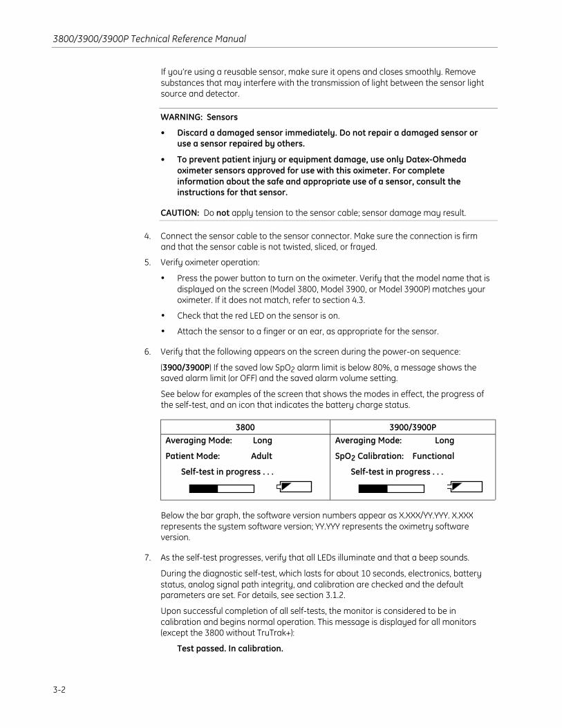
3800/3900/3900P Technical Reference Manual
3-2
If you’re using a reusable sensor, make sure it opens and closes smoothly. Removesubstances that may interfere with the transmission of light between the sensor lightsource and detector.
WARNING: Sensors
• Discard a damaged sensor immediately. Do not repair a damaged sensor oruse a sensor repaired by others.
• To prevent patient injury or equipment damage, use only Datex-Ohmedaoximeter sensors approved for use with this oximeter. For completeinformation about the safe and appropriate use of a sensor, consult theinstructions for that sensor.
CAUTION: Do not apply tension to the sensor cable; sensor damage may result.
4. Connect the sensor cable to the sensor connector. Make sure the connection is firmand that the sensor cable is not twisted, sliced, or frayed.
5. Verify oximeter operation:
• Press the power button to turn on the oximeter. Verify that the model name that isdisplayed on the screen (Model 3800, Model 3900, or Model 3900P) matches youroximeter. If it does not match, refer to section 4.3.
• Check that the red LED on the sensor is on.
• Attach the sensor to a finger or an ear, as appropriate for the sensor.
6. Verify that the following appears on the screen during the power-on sequence:
(3900/3900P) If the saved low SpO2 alarm limit is below 80%, a message shows thesaved alarm limit (or OFF) and the saved alarm volume setting.
See below for examples of the screen that shows the modes in effect, the progress ofthe self-test, and an icon that indicates the battery charge status.
3800 3900/3900PAveraging Mode: Long
Patient Mode: Adult
Self-test in progress . . .
Averaging Mode: Long
SpO2 Calibration: Functional
Self-test in progress . . .
Below the bar graph, the software version numbers appear as X.XXX/YY.YYY. X.XXXrepresents the system software version; YY.YYY represents the oximetry softwareversion.
7. As the self-test progresses, verify that all LEDs illuminate and that a beep sounds.
During the diagnostic self-test, which lasts for about 10 seconds, electronics, batterystatus, analog signal path integrity, and calibration are checked and the defaultparameters are set. For details, see section 3.1.2.
Upon successful completion of all self-tests, the monitor is considered to be incalibration and begins normal operation. This message is displayed for all monitors(except the 3800 without TruTrak+):
Test passed. In calibration.

3/Test and Upgrade Procedures
3-3
If a problem is discovered during the self-test, the monitoring screen will not appearand the monitor is inoperable. To identify the problem, see chapter 4.
8. Verify that the SpO2, pulse rate, and PIr pulsatile values and alarm limits display within15 seconds after the self-test is complete. Dashes (- - -) may appear for the values untilthe readings have stabilized and for alarm limits set to OFF.
NOTE: The audible alarm feature for all alarm conditions is silenced for the first twominutes after powering on.
9. When two minutes have elapsed since you powered on, remove the sensor from thefinger (or ear) and verify that the SENSOR OFF or CHECK SENSOR SITE messageappears, the alarm tone sounds, and an alarm light flashes.
10. Press the alarm silence button and verify that the alarm is silenced.
11. Randomly adjust an alarm limit and a volume limit to verify button function.
12. To verify oximeter operation on battery power, power off the oximeter and disconnectit from AC mains power. Then, repeat steps 5 through 11.
NOTE: If the remaining battery power is not sufficient to power on the unit, a low-battery icon is displayed and the monitor shuts off. Recharge the battery and continuewith the checkout.
3.1.1 Printer test (3900P)1. Power on the oximeter and hold down the left-most button on the printer until the
Datex-Ohmeda logo (oximeter identification) screen appears.
The printer prints a test sheet similar to the one shown below until you press theprinter’s stop button.
DATEX-OHMEDA 3900PPRINTER SELF-TEST
PRESS STOP BUTTON TO STOP
123456789012345678901234567ABCDEFGHIJKLMNOPQRSTUVWXYZ
p0123456789$/>+@&#?=,.o2
Figure 3-1. Printer test sheet
2. To stop the self-test, press .
3. Verify that the header information prints correctly and that the text is legible. If theself-test was not successful, replace the printer board; see section 5.7.1.

3800/3900/3900P Technical Reference Manual
3-4
3.1.2 Diagnostic self-testThe following self-tests are performed during power-on:
• All external static RAM and the processors’ SIM RAM are completely tested forfunctionality.
• FLASH ROM memory is CRC tested to verify unit software integrity.
• User-interface features (switches, display, and audio) are exercised in a prescribedmanner.
• A start-up tone sequence that tests the audio circuit is followed by illumination of alldisplay LEDs and the LCD backlight, which are then blanked.
• The alarm LED toggles between red and yellow while a numeric countdown from 9 to 0occurs on each 7-segment LED display, ending with a decimal point.
• A battery icon appears on the mode status screen of the LCD to indicate the batterycondition as follows:
Fully charged
Low
Depleted, not installed, or defective
• Oximeter circuit tests include supply and reference voltage checks, followed by a testsignal generated by the sensor LED drive circuit, which is routed through the oximetrysignal path to check for errors and verify calibration.
The resultant calculated value, which is sensitive to both offset and phase errors in thecircuitry, is compared to established criteria.
3.2 Electrical safety checkPerform this test after removing the oximeter cover to perform any service procedure.:
WARNING: Measure the leakage current in accordance with applicable standards aftercompleting any repair procedure.
1. With the power cord connected only to the oximeter, measure the resistance fromthe power plug ground connector to all exposed metal on the chassis. The measuredresistance must not exceed 0.15 Ω.
2. Measure the leakage current following the instructions supplied with the leakagecurrent tester.
3. Record the results for reference in future resistance/leakage tests. A significant changemay indicate a pending failure.

3/Test and Upgrade Procedures
3-5
3.3 Software upgradeAn IC (integrated circuit) chip is used to upgrade software. The IC chip is inserted into asocket on the system board. During the upgrade, the software is sent from the IC chip tothe system board (or oximetry board for monitors without TruTrak+).
• (TruTrak+ monitors) The system board software can be upgraded. An oximetry boardsoftware upgrade is not available for TruTrak+ monitors.
• (Monitors without TruTrak+) The system board software and the oximetry boardsoftware can be upgraded.
Important—3800: If system board software version 2.0 or higher is not installed on your3800, installation of the software upgrades listed below must be performed at a Datex-Ohmeda service center only:
• System board software version 2.000 or higher.
• Oximetry board software version 3.000 or higher.
Upgrade kit contentsThe upgrade kit contains a jumper plug that is used for the 3900/3900P system softwareupgrade. It also includes four software IC chips whose functions are described below.
IC Chip Software Upgrade Header J11on System Board
Model
U-LOADER System board YES Any 3800/3900/3900P containing thissystem board, including all3800/3900/3900P with TruTrak+
LOADER System board NO 3900/3900P without TruTrak+
SYS System board NO 3800 without TruTrak+
OXY Oximetry board Not applicable 3800/3900/3900P without TruTrak+
NOTE: The system board in TruTrak+ monitors (6050-0005-742) is also used as thereplacement board for any 3800/3900/3900P without TruTrak+. This board containsheader J11 (see Figure 3-2), which is not present on earlier system boards.
• If header J11 is on the system board in your monitor, use the U-LOADER chip.
• If header J11 is not on the system board in your 3900/3900P, use the LOADER chip.
• If header J11 is not on the system board in your 3800, use the SYS chip.
Tools• Phillips screwdriver, #1
• Flash IC extraction tool (PLCC extractor), REF 0380-1500-124

3800/3900/3900P Technical Reference Manual
3-6
3.3.1 Remove the cover and identify the system boardWARNING: Electrical shock hazard. Before cleaning or repairing the oximeter, turn itoff and disconnect it from AC mains power.
CAUTION: Static sensitivity. Internal electronic components are susceptible to damage byelectrostatic discharge. To avoid damage when disassembling the oximeter, observe thestandard precautions and procedures for handling static-sensitive components.
1. Turn off the oximeter and disconnect the power cord from the rear of the chassis.
2. Remove the two screws that secure the cover to the rear of the chassis.
3. Firmly press down on the cover and push it away from the front panel until it slips outof the locks on each side of the chassis.
4. To release the cover from the slots on the chassis, grasp both sides of the cover nearthe lower front corners and pull firmly outward. Lift the cover up; keep the sides free ofthe chassis.
5. (3900P) Continue with the following steps:
• Disconnect the printer cable from the printer board. Set the cover aside.
• Remove the two nuts from the screws that hold the catch tray to the chassis.Remove the two screws from the catch tray and chassis.
• Slowly pull the catch tray straight up and remove it from the unit.
6. (If you know whether or not your system board contains J11, skip this step.)Look for J11 on the system board (refer to Figure 3-2 for the location of J11).
• If necessary, loosen the oximetry board by removing the four screws that hold theboard to the standoffs. Slowly lift the board until you can see the part of thesystem board where J11 is located.
NOTE: If J11 is present, a jumper will be installed on it for the 3800; a jumper is notinstalled on J11 for the 3900/3900P.
• Reinstall the four screws that secure the oximetry board to the standoffs. Check tobe sure all cables are securely fastened.
7. Connect the power cord to the oximeter.
3.3.2 (Optional) Check the installed software versionsYou can determine if an upgrade is needed by checking the version number of thesoftware that is currently installed on your oximeter.
1. Turn on the oximeter.The version numbers are displayed below the self-test bar graph in this form:
Version X.XXX/YY.YYY
Note the version number of the installed software:
X.XXX (system software version number) = _______________
YY.YYY (oximetry software version number) = _______________
2. Turn off the oximeter.
3. If the installed software version is below the version shown on the corresponding ICchip, upgrade the software.

3/Test and Upgrade Procedures
3-7
3.3.3 System software upgrade using the U-LOADER or LOADER chipIf you are upgrading the system software, select the appropriate IC chip based on yourmonitor and the system board it contains:
• U-LOADER—use to upgrade a 3800, 3900, or 3900P whose system board containsheader J11.
• LOADER—use to upgrade a 3900 or 3900P whose system board does not containheader J11.
NOTE: To upgrade a 3800 whose system board does not contain header J11, go tosection 3.3.4.
To upgrade the system software, you install the appropriate IC chip on the system board,then power on the unit to download the software.
1. (3900/3900P) Install a jumper plug on J10 on the system board.
NOTE: A jumper is not used when upgrading the 3800 system software.
2. Locate the upgrade socket (U19) on the system board near the rear of the monitor.
J3
J4
J8J7
J10
SW1
U19
Oximetry Board System Board
IC ChipFron
t of M
onito
r Jumper(3900/3900P)
LOADER
or
U-LOADER
J11
Figure 3-2. Jumper plug, upgrade socket, and LOADER/U-LOADER IC chip
3. Carefully align the notch on the appropriate system software upgrade chip with thenotch on socket U19. Then, insert the chip into the socket.

3800/3900/3900P Technical Reference Manual
3-8
4. Turn on the oximeter. Messages similar to those shown below are displayed.
System Loader VX.XXX...Testing
Updating System to VX.XXXSize (bytes): XXXXXPress to begin →→→→
NOTE: (3900/3900P only) If the jumper ismissing or incorrectly installed, you willsee the normal power-on screens andmessages. The system software will notbe upgraded. Power off and begin again,starting with step 1.
The arrow means press the pulse rate low alarm limit button (either side) to start thesystem upgrade.
Updating System to VX.XXXSize (bytes): XXXXXErasing...
Updating System to VX.XXXSize (bytes): XXXXXProgramming XXXX
Updated to Version VX.000SUCCESS!Cycle power …
NOTE: Contact Datex-Ohmeda to obtain a new upgrade chip if the upgrade does notproceed as described above and the CRC BAD! or INCOMPATIBLE! error message isdisplayed.
• CRC BAD! indicates an incorrect or damaged IC chip.
• INCOMPATIBLE! means the upgrade software is not compatible with youroximeter.
These errors do not affect the previously-installed software. You can stop the systemupgrade and the monitor will return to its prior operating condition. You may upgradethe oximetry software if you had planned to do so.
If either message appears, turn off the oximeter. Then, go to step 6.
5. When the Cycle power message is displayed, turn off the oximeter.
6. Use an IC chip extraction tool to remove the IC chip from the socket.
7. (3900/3900P) Remove the jumper plug from J10.
8. (Monitors without TruTrak+) To upgrade the oximetry software, go to section 3.3.5.
or
Go to section 3.3.6 to install the cover and check the installation.

3/Test and Upgrade Procedures
3-9
3.3.4 System software upgrade using the SYS chipIf the system board in your 3800 does not contain header J11, install the SYS chip on thesystem board, then power on to download the software.
1. Locate the upgrade socket (U19) on the system board near the rear of the monitor.
J3
J4
J8J7
SW1
U19
Oximetry Board System Board
IC ChipFron
t of M
onito
r
SYS
Figure 3-3. Upgrade socket and SYS IC chip
2. Carefully align the notch on upgrade chip SYS X.XXX with the notch on socket U19.Then, insert the chip into the socket.
3. Turn on the oximeter. Messages similar to those shown below are displayed.
System Download in Progress...Erasing...
System Download in Progress...Progress: XX%Retries: XX
CYCLE POWERProgress: 100%Retries: XXUpdated to Ver Y.YYY

3800/3900/3900P Technical Reference Manual
3-10
NOTE: Contact Datex-Ohmeda to obtain a new upgrade chip if the upgrade does notproceed as described above and the CRC BAD! or INCOMPATIBLE! error message isdisplayed.
• CRC BAD! indicates an incorrect or damaged IC chip.
• INCOMPATIBLE! means the upgrade software is not compatible with youroximeter.
These errors do not affect the previously-installed software. You can stop the systemupgrade and the monitor will return to its prior operating condition. You may upgradethe oximetry software if you had planned to do so.
If either message appears, turn off the oximeter. Then, go to step 5.
4. When the Cycle power message is displayed, turn off the oximeter.
5. Use an IC chip extraction tool to remove the IC chip from the socket.
6. To upgrade the oximetry software, go to section 3.3.5.
or
Go to section 3.3.6 to install the cover and check the installation.

3/Test and Upgrade Procedures
3-11
3.3.5 Oximetry software upgrade (monitors without TruTrak+)To upgrade the oximetry software, you install the OXY Y.YYY IC chip on the system boardand power on the unit to download the software to the oximetry board.
1. Locate the upgrade socket (U19) on the system board near the rear of the monitor.
J3
J4
J8J7
SW1
U19
Oximetry Board System Board
IC ChipFron
t of M
onito
r
OXY
J10
Figure 3-4. Upgrade socket and OXY IC chip
2. Carefully align the notch on upgrade chip OXY Y.YYY with the notch on socket U19.Then, insert the chip into the socket.
3. Turn on the oximeter. Messages similar to those listed below are displayed.
Oximetry Download in ProgressProgress: ErasingRetries: XX
Oximetry Download in ProgressProgress: XX%Retries: XX
CYCLE POWERProgress: 100%Retries: XXUpdated to Ver Y.YYY
(3900/3900P) If a jumper is installed onJ10, an alarm sounds and the screenremains blank. The jumper is for3900/3900P system software upgradesonly and should not be used for oximetrysoftware upgrades.
To correct this situation:
• Turn off the oximeter.
• Remove the jumper from J10.
• Turn on the oximeter.

3800/3900/3900P Technical Reference Manual
3-12
NOTE: Contact Datex-Ohmeda to obtain a new upgrade chip if the upgrade does notproceed as described above and the CRC BAD! or INCOMPATIBLE! error message isdisplayed.
• CRC BAD! indicates an incorrect or damaged IC chip.
• INCOMPATIBLE! means the upgrade software is not compatible with youroximeter.
These errors do not affect the previously-installed software. You can stop the systemupgrade and the monitor will return to its prior operating condition. You may upgradethe oximetry software if you had planned to do so.
If either message appears, turn off the oximeter. Then, go to step 5.
4. When the CYCLE POWER message is displayed, turn off the oximeter.
5. Use an IC chip extraction tool to remove the IC chip from the socket.Then, go to section 3.3.6 to install the cover and check the installation.
3.3.6 Install the cover and check the installation1. (3900P) Replace the catch tray and connect the printer cable:
• Place the catch tray tube directly over the hole in the bottom of the chassis.
• Align the holes in the catch tray with the holes in the chassis. Reinstall the twoscrews through the chassis and the catch tray. Make sure the tube remains in thechassis hole.
• Reinstall the two nuts to the screws to anchor the catch tray to the chassis.
• Position the cover above the chassis and connect the printer cable to the printerboard.
• To avoid disconnecting the printer cable, position the cover so that the tabs oneach side of the cover are directly above the capture slots on the chassis.
2. Grasp both sides of the cover near the lower front corners; firmly pull outward. Lowerthe cover until the tabs on each side of the cover drop into the slots on the chassis.
3. Push the cover forward until it “locks” into place against the front panel.
4. Reinstall the two screws that secure the cover to the rear of the chassis.
5. To verify the software installation, turn on the oximeter.
The version numbers for the installed system and oximetry software appear on thescreen during the power-on sequence.
(3900P) If Model 3900 (not Model 3900P) is displayed when you turn on the 3900P, youmay have disconnected the printer cable while installing the cover. To reconnect thecable:
• Turn off the oximeter.
• Remove the cover, connect the cable to the printer board, and reinstall the cover.
• Power on the oximeter and verify that Model 3900P is displayed.
Important: Perform the Functional check (section 3.1) and the Electrical safety check(section 3.2).

4-1
4/TroubleshootingThis chapter contains:
• An alphabetical list of the messages that may appear while using the oximeter and the3900P printer.
• A list of the error codes that appear with a SYSTEM FAILURE message.
• A troubleshooting guide for the oximeter and the 3900P printer.
• 3900/3900P TeleOximetry® messages and troubleshooting guide.
• Test points on the System and Oximetry boards.
4.1 MessagesThe following chart alphabetically lists the messages that may appear on the oximeter,why the message appears, and the action(s) to take if the message indicates a problem.
NOTE: Messages that may be displayed while using the 3900/3900P TeleOximetry featureare described in section 4.4.
Message Cause Action
Appears in the graphicdisplay alarm limit area.
The all mute feature is activated. No action required. (Press the alarmsilence button once to deactivate.)
Appear on status screenduring power-on sequence
and on right side of LCDduring battery operation.
Indicates a fully charged battery.
Indicates a low-charged battery.
No action required.
To recharge, plug the unit into AC mainspower.
Appears on status screenduring power-on sequence.
Indicates battery failure, a depletedbattery, or a missing battery.
To recharge, plug the unit into AC mainspower. If the condition persists, the unitrequires service.
+Appears in the graphicdisplay message area.
The alarm or pulse tone volume isbeing adjusted.
No action required. To adjust audiovolume, refer to the User’s Manual.
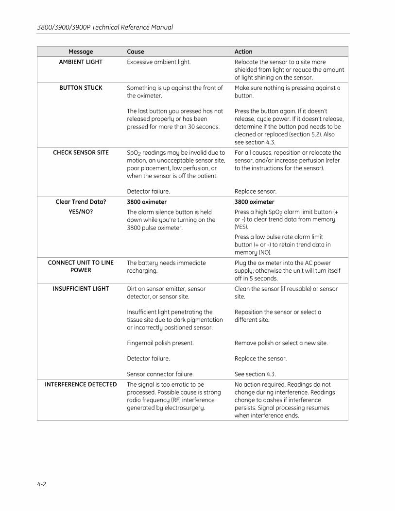
3800/3900/3900P Technical Reference Manual
4-2
Message Cause Action
AMBIENT LIGHT Excessive ambient light. Relocate the sensor to a site moreshielded from light or reduce the amountof light shining on the sensor.
BUTTON STUCK Something is up against the front ofthe oximeter.
The last button you pressed has notreleased properly or has beenpressed for more than 30 seconds.
Make sure nothing is pressing against abutton.
Press the button again. If it doesn’trelease, cycle power. If it doesn’t release,determine if the button pad needs to becleaned or replaced (section 5.2). Alsosee section 4.3.
CHECK SENSOR SITE SpO2 readings may be invalid due tomotion, an unacceptable sensor site,poor placement, low perfusion, orwhen the sensor is off the patient.
Detector failure.
For all causes, reposition or relocate thesensor, and/or increase perfusion (referto the instructions for the sensor).
Replace sensor.
Clear Trend Data?
YES/NO?3800 oximeter
The alarm silence button is helddown while you’re turning on the3800 pulse oximeter.
3800 oximeter
Press a high SpO2 alarm limit button (+or -) to clear trend data from memory(YES).
Press a low pulse rate alarm limitbutton (+ or -) to retain trend data inmemory (NO).
CONNECT UNIT TO LINEPOWER
The battery needs immediaterecharging.
Plug the oximeter into the AC powersupply; otherwise the unit will turn itselfoff in 5 seconds.
INSUFFICIENT LIGHT Dirt on sensor emitter, sensordetector, or sensor site.
Insufficient light penetrating thetissue site due to dark pigmentationor incorrectly positioned sensor.
Fingernail polish present.
Detector failure.
Sensor connector failure.
Clean the sensor (if reusable) or sensorsite.
Reposition the sensor or select adifferent site.
Remove polish or select a new site.
Replace the sensor.
See section 4.3.
INTERFERENCE DETECTED The signal is too erratic to beprocessed. Possible cause is strongradio frequency (RF) interferencegenerated by electrosurgery.
No action required. Readings do notchange during interference. Readingschange to dashes if interferencepersists. Signal processing resumeswhen interference ends.

4/Troubleshooting
4-3
Message Cause Action
LOW BATTERY 5 to 15 minutes of battery operationremain; i.e., battery voltage < 7.3 V.
Plug oximeter into the AC power supplyto recharge the battery.
Important: To prevent permanentdamage to the battery, recharge adischarged battery within eight hoursafter the LOW BATTERY message isdisplayed.
LOW QUALITY SIGNAL Sensor off patient.
Perfusion insufficient for validreadings.
Motion at sensor site, electricalnoise, or incorrect sensorplacement.
Reattach the sensor.
Check patient and oximeter setup;reposition or relocate sensor.
Check patient and oximeter setup;eliminate source of motion/noise.
Model 3800 Pulse Oximeteror
Model 3900 Pulse Oximeteror
Model 3900P Pulse Oximeter(on product identification
screen)
Version X.XXX/YY.YYY
(on second power-up screen)
Appears briefly when you power onthe oximeter.
• X.XXX represents the currentsystem software version.
• YY.YYY represents the currentoximetry software version.
(3900P) If Model 3900 (not Model3900P) is displayed, the printer cablemay be disconnected.
No action required.
(3900P) Reconnect the printer cable:
• Turn off the oximeter.
• Remove the cover, reconnect thecable, and reinstall the cover.
• Power on the oximeter and verifythat Model 3900P is displayed.
NO SENSOR
((((aaaallllssssoooo sssseeeeeeeeCHECK SENSOR SITE))))
Sensor not fully inserted into thesensor connector.
May be an incorrect sensor.
Insert sensor plug into the connector.
Refer to the instructions for the sensor.
PRINTER FAILURE 3900P printer
Printer paper jam.
Printer has failed.
3900P printer
Remove the jammed paper. Refer to the3900/3900P User’s Manual
Service printer; see section 5.7.

3800/3900/3900P Technical Reference Manual
4-4
Message Cause Action
SENSOR FAILURE The connected sensor is not anOxyTip+ sensor.
Oximeter can’t identify theconnected sensor.
Inoperative LEDs or broken sensorcable wire; the sensor has failed.
Oximeter’s sensor circuitry has failed.
Use only OxyTip+ sensors.
Replace the sensor. Refer to theinstructions for the sensor.
Replace sensor.
Replace the oximetry board; seesection 5.6.
SENSOR OFF Sensor off patient.
Oximeter’s sensor circuitry failed.
Reattach the sensor.
Replace sensor. If the condition persists,replace the oximetry board; seesection 5.6.
SYSTEM FAILURE #XXX:SERVICE UNIT
Internal component has failed.XXX = error code for the type ofsystem failure.
See section 4.2.
TruTrak+ OFF TruTrak+ monitors
TruTrak+ is not active; the averagingmode is not set to Long.
TruTrak+ monitors
Set the Mode Switch to the Longaveraging mode (refer to the User’sManual for instructions).
WAITING FOR SOFTWAREDOWNLOAD
Monitors without TruTrak+
Software upgrade is in progress.
Oximetry board has no software; thesoftware download was notcompleted.
Monitors without TruTrak+
No action required.
Reload the oximetry board software;see section 3.3.

4/Troubleshooting
4-5
4.2 System failure error codes4.2.1 Nonfatal errors—the system continues running
Error code Meaning Cause Action
4 Erase flash failure Software could not erase asector of the system boardFlash memory.
Replace system board.; see section 5.5.
20 Buffer full failure Software buffer overflow. No action necessary.
21 Queue full failure Software buffer overflow. Check the connection between the unit andcommunicating device. Verify serialcommunication setup (baud rate, stop/startbit, and parity).
52 Oximeter responsefailure
Communications errorbetween system andoximetry boards.
Upgrade system and/or oximetry softwareas applicable for your monitor; see section3.3.
53 Oximeter timeoutfailure
Oximetry board failed torespond within theappropriate amount oftime.
Check the connection between the oximetryboard and the system board.
(Monitors without TruTrak+) Upgradeoximetry software; see section 3.3.
Replace oximetry board; see section 5.6.
55 Oximeter user errorfailure
Improper communicationsfrom system to oximetryboard.
Incompatible system andoximetry software versions.
Upgrade system and/or oximetry softwareas applicable for your monitor; seesection 3.3.
57 Oximeter valuefailure
Communications errorbetween system andoximetry boards.
Incompatible system andoximetry software versions.
Upgrade system and/or oximetry softwareas applicable for your monitor; seesection 3.3.

3800/3900/3900P Technical Reference Manual
4-6
4.2.2 Fatal errors—the system sounds an alarm tone and halts
Error code Meaning Cause Action
101 Appl CRC failure System board applicationcode corrupted or notprogrammed.
Reinstall system board software; seesection 3.3.
Replace system board; see section 5.5.
102 Boot CRC failure Invalid system boot code. Replace system board; see section 5.5.
103 RAM failure Error in system boardRAM.
If the error occurs only occasionally, maybe random causes (e.g., static discharge).If it occurs repeatedly, replace systemboard; see section 5.5.
110 Execution failure Error in system boardRAM or the data/addressbuses.
If the error occurs only occasionally, maybe random causes (e.g., static discharge).If it occurs repeatedly, replace systemboard; see section 5.5.
111 Reset failure System board processorwas reset due to a buserror.
If the error occurs only occasionally, maybe random causes (e.g., static discharge).If it occurs repeatedly, replace systemboard; see section 5.5.
112 Unused interrupt failure Error in system boardRAM or the data/addressbuses.
If the error occurs only occasionally, maybe random causes (e.g., static discharge).If it occurs repeatedly, replace systemboard; see section 5.5.
113
114
Watchdog failure
Guard-dog failure
System board softwaretiming failure.
Upgrade system board software; seesection 3.3.
Replace system board; see section 5.5.
120122130131132133134135136137138139140141142143144
Buffer full failureValue failureEvent signal failureEvent wait failureMail create failureMail send failureMail wait failureResource get failureResource release failureResource reserve failureTask create failureTask stack failureTask trig failureTask wait failureTimer create failureTimer start failureTimeout failure
Internal system softwarecheck failed.
Upgrade the system board software; seesection 3.3.

4/Troubleshooting
4-7
Error code Meaning Cause Action
150 Oximeter error countfailure
Too many errors inoximetercommunications.
Check cable connection between systemand oximeter board.
If the error occurs only occasionally,may be random causes (e.g., staticdischarge).
(Monitors without TruTrak+) Upgradeoximetry software if error occursrepeatedly; see section 3.3.
If the error persists, replace the oximetryboard; see section 5.6.
151 Oximeter commandfailure
System board attemptedto transmit an invalidcommand to the oximetryboard.
Check cable connection between systemand oximeter board.
If the error occurs only occasionally, maybe random causes (e.g., static discharge).If it occurs repeatedly, upgrade systemboard software; see section 3.3.
If the error persists, replace the systemboard; see section 5.5.
154 Oximeter sysfail failure Oximetry board detectedan internal error andhalted operation.
Check cable connection between systemand oximeter board.
If the error occurs only occasionally, maybe random causes (e.g., static discharge).
(Monitors without TruTrak+) Upgradeoximetry software if error occursrepeatedly; see section 3.3.
If the error persists, replace the oximetryboard; see section 5.6.
156 Oximeter reset failure Oximetry board fails tocommunicate at all.
Check cable connection between systemand oximeter board.
(Monitors without TruTrak+) Reinstalloximetry software, see section 3.3.
Replace the oximetry board; seesection 5.6.
157 Oximeter value failure System board receivesinvalid data fromoximeter board.
Check cable connection between systemand oximeter board
If the error occurs only occasionally,may be random causes (e.g., staticdischarge).
(Monitors without TruTrak+) Upgradeoximetry software if error occursrepeatedly; see section 3.3.
If the error persists, replace the oximetryboard; see section 5.6.

3800/3900/3900P Technical Reference Manual
4-8
4.3 Troubleshooting guideThe following chart lists situations that may occur while using the oximeter and the 3900Pprinter. These situations do not generate a message. Follow the recommended action(s) inthe order listed until the cause is isolated and corrected.
NOTE: Situations that may occur while using the 3900/3900P TeleOximetry feature aredescribed in section 4.4.
Situation/Cause Action
Unit does not power on.Battery discharged
Fuses blown
Power supply failure
Battery failure
Switch board failure
System board failure
Plug the unit into AC power; verify that the green power light is on.
Check the fuses. Replace if necessary; see section 5.3.4.
Remove the cover; see section 5.1.1.
Check the power connection to the system board.
Check for +12 V at J8, pin 4 (+) to J8, pin1 (-).
Check the battery connections.
Measure the voltages between the power supply and the battery;see section 4.5.1.
Replace the battery; see section 5.3.5.
To check the power button on the switch board,
• Remove the front panel assembly; see section 5.2.
• Unplug the switch board ribbon cable from the system board.
• Check the power button switch on pins 16 and 44 on the ribboncable.
• Replace the switch board; see section 5.2.
Replace the system board; see section 5.5.
Unit powers on but the graphicdisplay is blank or black.
Viewing contrast incorrect
LCD failure
Switch board failure
System board failure
Adjust viewing contrast slider.
Remove the front panel assembly; see section 5.2.
Check the resistance of the viewing contrast potentiometer at J1; mustbe between 0 and 50 kΩ.
Check the LCD connector pins and the switch board LCD connector fordamage.
Replace the switch board LCD; see section 5.2.
Replace the switch board; see section 5.2.
Replace the system board; see section 5.5.

4/Troubleshooting
4-9
Situation/Cause Action
Unit powers on, an audible beepsounds, but there are no displays.
Switch board failure
System board failure
Remove the front panel assembly; see section 5.2.
Check the ribbon cable from the switch board to the system board forproper seating in the connector, for bent pins, or for damage.
On the system board, check at J1, pin 1 to pin 4, for +5 V.
Replace the switch board; see section 5.2.
Replace the system board; see section 5.5.
Unit powers on but no audible beep.Speaker disconnected
Speaker failure
System board failure
Remove the cover; see section 5.1.1.
Check speaker connection to system board; see section 5.4.
Replace the speaker; see section 5.4.
Replace the system board; see section 5.5.
Model name displayed at power on isnot correct.
(3900P) Printer cable isdisconnected
Model ID jumper on systemboard is/is not installed formodel
Turn off oximeter, remove cover, reconnect printer cable, and reinstallcover. Verify that Model 3900P is displayed at power on.
Check J11 on system board for presence/absence of jumper:
• Model 3800—jumper should be installed on J11.
• Models 3900 and 3900P—jumper should not be installed on J11.
Continuous speaker tone.System board failure Replace the system board; see section 5.5.
BUTTON STUCK message or button(s)not working.
Dirty/worn buttons
Switch board failure
System board failure
Remove the front panel assembly; see section 5.2.
Check button pads. Clean the button pads, check for damage; replaceif necessary; see section 5.2.
Replace the switch board; see section 5.2.
Replace the system board; see section 5.5.
Fuses fail shortly after replacement.Shorts or power supply failure.
System board failure
Remove the cover; see section 5.1.1.
Disconnect the power inlet module from the power supply;see section 5.3.3.
Check for shorts between the wires from the power inlet module.
Replace the power supply; see section 5.3.1.
Replace the system board; see section 5.5.

3800/3900/3900P Technical Reference Manual
4-10
Situation/Cause Action
No response or wrong response fromdip switch setting(s).
Dip switch failure Replace the system board; see section 5.5.
Battery won’t charge.Battery failure
System board failure
Plug the unit into AC power; verify that the green power light is on.
Remove the cover; see section 5.1.1.
Check battery connections.
Measure the battery voltages across 1 red and 1 black wire; should bebetween 6.5 and 9.5 volts.
Replace the battery; see section 5.3.5.
Replace the system board; see section 5.5.
Green power light remains off whenunit is connected to AC power.
Fuses blown
Power cord failure
Power supply failure
Switch board failure
System board failure
Check the fuses. Replace if necessary; see section 5.3.4.
Check the power cord; replace if necessary.
Remove the cover; see section 5.1.1.
Check the power supply voltages; see section 4.5.1.
Replace power supply; see section 5.3.1.
Remove the front panel assembly; see section 5.2.
Disconnect the ribbon cable from the system board.
Test for voltage on J1 on the ACLED pin, pin 14, on the system board.
Replace the switch board; see section 5.2.
Replace the system board; see section 5.5.
Green power light remains on whenunit is disconnected from AC power.
System board failure Replace the system board; see section 5.5.
Unit will not enter standby mode.Switch board failure
System board failure
Remove the cover; see section 5.1.1.
To check the power button on the switch board,
• Remove the front panel assembly; see section 5.2.
• Unplug the switch board’s ribbon cable from the system board.
• Check power button switch on pins 16 and 44 on the ribbon cable.
• Replace the switch board; see section 5.2.
Replace the system board; see section 5.5.
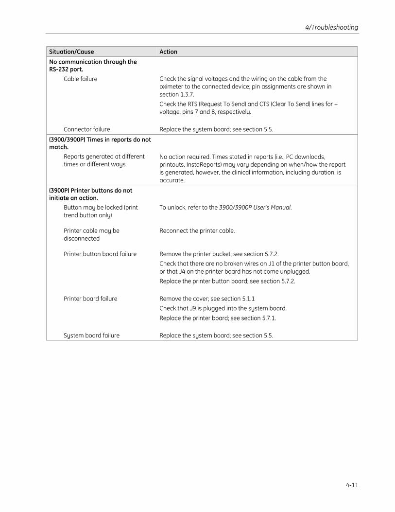
4/Troubleshooting
4-11
Situation/Cause Action
No communication through theRS-232 port.
Cable failure
Connector failure
Check the signal voltages and the wiring on the cable from theoximeter to the connected device; pin assignments are shown insection 1.3.7.
Check the RTS (Request To Send) and CTS (Clear To Send) lines for +voltage, pins 7 and 8, respectively.
Replace the system board; see section 5.5.
(3900/3900P) Times in reports do notmatch.
Reports generated at differenttimes or different ways
No action required. Times stated in reports (i.e., PC downloads,printouts, InstaReports) may vary depending on when/how the reportis generated, however, the clinical information, including duration, isaccurate.
(3900P) Printer buttons do notinitiate an action.
Button may be locked (printtrend button only)
Printer cable may bedisconnected
Printer button board failure
Printer board failure
System board failure
To unlock, refer to the 3900/3900P User’s Manual.
Reconnect the printer cable.
Remove the printer bucket; see section 5.7.2.
Check that there are no broken wires on J1 of the printer button board,or that J4 on the printer board has not come unplugged.
Replace the printer button board; see section 5.7.2.
Remove the cover; see section 5.1.1
Check that J9 is plugged into the system board.
Replace the printer board; see section 5.7.1.
Replace the system board; see section 5.5.

3800/3900/3900P Technical Reference Manual
4-12
4.4 3900/3900P TeleOximetry messages andtroubleshooting
4.4.1 TeleOximetry status messagesThese messages may be displayed on the oximeter when you send data to a remotecomputer or to a fax machine, using a modem (or fax modem) connected to the oximeter. Themeaning and response (if applicable) for each message is included.
NOTE: For status messages and error messages related to using the TeleOximetry PCAccess software, refer to the instructions located on the TeleOximetry CD.
Status message (oximeter) Meaning/Response
BUSY The fax machine or phone line is busy. The modem redials the number untilthe fax machine or phone line is no longer busy or until you press CANCEL.
CONNECTING… The FAX machine has answered the phone.
CONNECTION FAILURE The modem cannot contact the fax machine or remote computer.
Verify that the phone number was entered correctly and the remoteequipment (fax machine, modem and/or computer) is powered on. If themessage persists, the phone system used by the oximeter modem mayrequire a guard tone. To set the guard tone, see the 3900/3900P User’sManual.
DIAL REMOTE COMPUTER The modem is dialing the number of the modem associated with the remotecomputer.
DIALING REMOTE FAX The modem is dialing the number you entered for the fax machine.
FAX CANCELED When you cancel a fax transmission, this message is displayed on the screenand transmitted to the fax machine.
FAX DONE Fax transmission is complete. The modem disconnects the phone line. Press to return to the SEND screen.
FAX ERROR A nonrecoverable error occurred during transmission of a fax.
This message indicates a problem with your modem, the phone line, or thefax machine. Check the connection, setup, and function of all thesecomponents. Verify that you are faxing to a Group 3 fax machine.
FOUND The oximeter detected the modem that is connected to the oximeter.
INITIALIZATION STRINGFAILURE
The modem rejected the initialization string.
Make sure you entered the initialization string correctly (see the 3900/3900PUser’s Manual). If the entry is correct, consult the instructions for yourmodem.
NO ANSWER There is no answer after the number is dialed.
Verify that you entered the number correctly and the remote equipment (faxmachine, modem and/or computer) is powered on.
NO DATA You tried to send a fax that covered only hours during which no numeric datawere collected. For example, if numeric data were collected two hours earlier,but not during the last hour of operation, you can send two or more hours ofdata, but not one. This eliminates the possibility of sending an InstaReportthat contains no numeric data.

4/Troubleshooting
4-13
Status message (oximeter) Meaning/Response
NO DIAL TONE The modem cannot find a dial tone when attempting to call the number.
Verify that the modem is properly connected to the correct phone line..
NOT FOUND: CONNECTMODEM
The oximeter modem was not detected by the oximeter.
Check and correct all connections between the oximeter and modem. Poweron the modem. If the message persists, refer to section 4.4.2.
SEARCHING… The oximeter is searching for the modem (you selected MODEM at the MENUscreen).
SENDING FAX… The connection process is complete and the fax is being sent.
SENDING DATA… REMOTE COMPUTER option: Data is being sent to a remote computer.
or
WAIT FOR CALL option: Your modem received the call and is sending data tothe remote computer.
TRANSMISSION CANCELED You canceled a remote computer transmission. This message is transmittedto the remote computer.
TRANSMISSION DONE Transmission to a remote computer (using the REMOTE COMPUTER or theWAIT FOR CALL option on the oximeter SEND screen) is complete. The modemdisconnects the phone line. Press to return to the SEND screen.
TRANSMISSION ERROR A nonrecoverable error occurred during transmission of data to a remotecomputer.
This message indicates a problem with your modem, the phone line, theremote modem, or the remote computer. Check the connections, setup, andfunction of all these components.
WAITING FOR CALL The modem is waiting for an incoming call. You may not use the 3900Pprinter while the modem is active. To cancel the transmission, press CANCEL.

3800/3900/3900P Technical Reference Manual
4-14
4.4.2 TeleOximetry troubleshooting guideThe situations listed below may occur while using a modem that is connected to the 3900or 3900P.
NOTE: Situations related to using the TeleOximetry PC Access software on your PC aredescribed in the instructions located on the TeleOximetry CD.
Situation Cause Action
No communication throughthe modem that is connectedto the oximeter.
Incorrect cable used to connectmodem to oximeter.
Modem is powered off or notproperly connected. Phone linefailure.
Incorrect or improperly enteredmodem initialization string.
Your phone system may require aguard tone.
Mismatched baud rate.
Modem failure.
Use only the Datex-Ohmedamodem/analog cable. Refer to section6.1.
Check and correct all modemconnections. Power on the modem.Check the phone line.
Check initialization string entry. Verifythe accuracy of the string.3900/3900P User’s Manual.
Enter a guard tone, if needed. Refer tothe 3900/3900P User’s Manual.
For some older modems, theoximeter’s baud rate must be set tomatch the modem’s baud rate. To setthe oximeter’s baud rate, refer to the3900/3900P User’s Manual.
Contact the modem manufacturer forassistance.
Data transmission from theoximeter is very slow or failsrepeatedly.
The data transfer rate of the modemconnected to the oximeter is toolow.
Use a 56K modem or fax modem.

4/Troubleshooting
4-15
4.5 Test points4.5.1 System board test points
See section 6.5 for the placement of test points on the system board.
NOTE: TP2, TP3, TP4, TP7, and TP8 are not used.
Test point Signal name Description
TP1 LOWBAT’ Battery voltage has dropped below 7.3 V
TP5 ISOLATED GND Isolated circuit reference
TP6 RECHRG’ Battery voltage has dropped below 7.0 V (reset bymains power applied)
TP9 AUDIO AMP IN Sawtooth (alarms)/square wave (pulse)
TP10 SAWTOOTH OUT Sawtooth waveform at approx. 8 kHz
TP11 RXD’ Received oximeter board data
TP12 TXD’ Data transmitted to oximeter board
TP13 DGND Digital ground reference
TP14 +VSW If on battery, then battery voltage –0.3 V else 11.5V (unit operating)
TP15 +VRAM +5 V with unit operating, +4 V in standby mode
TP16 +VR +4 V in standby mode
TP17 ON High when unit is on, low when unit is in standby
TP18 RST’ Normally high, low when processor is being reset
TP19 RECHRG Battery voltage is above 7 V
TP20 +5D +5 V
TP21 DGND Digital ground reference

3800/3900/3900P Technical Reference Manual
4-16
4.5.2 Oximetry board test pointsSee section 6.6 for the placement of test points on the oximetry board(s).
Oximetry board in TruTrak+ monitors (REF 6050-0006-066)
Test point Signal name Description
TP1 PRE Detector preamp output
TP2 TEST SIG Test signal amplifier output
TP3 LPF1 OUT LP filtered detector or test signal
TP4 INTF Output of interference detection amplifier andintegrator
TP5 COMP GAIN OUT Multiplexed detector signal after composite gain(varies based on detector signal)
TP6 RDC Red composite signal after LP filter
TP7 IRDC Infrared composite signal after LP filter
TP8 IRDCHP IRDC after HP filter
TP9 RDCHP RDC after HP filter
TP10 RESET Normally low/high when processor being reset
TP11 AC GAIN IN Input to AC gain amplifier(multiplexed RDCHP and IRDCHP)
TP12 AC GAIN OUT Output of AC gain amplifier(multiplexed RAC and IRAC)
TP13 RAC Red photoplethysmographic waveform
TP14 IRAC Infrared photoplethysmographic waveform
TP15 AD MUX OUT A/D multiplexed signal for all channels, scaled by0.78
TP16 AMUX A/D multiplexor output, scaled by 0.39 and level-shifted
TP17 VREF + 4.1 volt reference voltage

4/Troubleshooting
4-17
Oximetry board in monitors without TruTrak+ (REF 6050-0003-745)
Test point Signal name Description
TP1 COMP GAIN OUT Multiplexed detector signal after composite gain(varies based on detector signal)
TP2 IRDC Infrared composite signal after LP filter
TP3 IRDCHP IRDC after HP filter with variable pole
TP4 RDCHP RDC after HP filter with variable pole
TP5 RDC Red composite signal after LP filter
TP6 AD MUX OUT A/D multiplexed signal for all channels
TP7 IRAC Infrared photoplethysmographic waveform
TP8 SCCLOCK Switched capacitor filter clock (1 kHz)
TP9 AC GAIN OUT Multiplexed RDCHP and IRDCHP after gain
TP10 LP PREA LP filtered detector or test signal
TP11 TEST SIG Test signal amplifier output
TP12 MUX3’ Low when U16 A/D MUX is selected
TP13 RAC Red photoplethysmographic waveform
TP14 AC GAIN IN Input to AC gain amplifier, multiplexed
TP15 AGND Analog ground reference
TP16 RESET’ Normally high, low when processor being reset
TP17 SRAM_CE Low when static ram is enabled
TP18 BUFF AD MUX OUT Buffered A/D multiplexor output
TP19 DAC_CE’ Low when D/A converter is enabled
TP20 AGND Analog ground reference
TP21 PGM High when flash memory is being programmed
TP22 INST High during instruction fetches
TP23 A16 Address bus line 16
TP24 AGND Analog ground reference

3800/3900/3900P Technical Reference Manual
4-18

5-1
5/Repair and Replacement ProceduresThis chapter contains:
• Oximeter cover, removal and replacement.
• Replacement of front panel components:
Front panel
Sensor connector
(Monitors without TruTrak+) Sensor filter board
(TruTrak + monitors ) Sensor filter flex cable
Switch board LCD
Button pads
Switch board
• Replacement of power-related components:
Power supply
Equipotential ground connector
Power inlet module
Fuses
Battery
• Speaker replacement
• System board replacement
• Oximetry board replacement
• Replacement of 3900P printer components:
Printer board
Printer button board
CAUTION: Only qualified service personnel should perform the procedures described inthis manual.
(3900/3900P) Datex-Ohmeda does not warrant or service modems. Contact themanufacturer of your modem for service.
Refer to chapter 6 for service kit contents, part numbers, assembly drawings, and boardlayout drawings.
Important: If the cover is removed for any test or repair procedure, always performthe Functional check (section 3.1) and the Electrical safety check (section 3.2) beforereturning the unit for patient monitoring.

3800/3900/3900P Technical Reference Manual
5-2
5.1 Oximeter coverImportant: If the cover is removed for any test or repair procedure, always performthe Functional check (section 3.1) and the Electrical safety check (section 3.2) beforereturning the unit for patient monitoring.
Tool: Phillips screwdriver, #1
5.1.1 Removing the coverWARNING: Electrical shock hazard. Before cleaning or repairing the oximeter, turn itoff and disconnect it from AC mains power.
CAUTION: Static sensitivity. Internal electronic components are susceptible to damageby electrostatic discharge. To avoid damage when disassembling the oximeter,observe the standard precautions and procedures for handling static-sensitivecomponents.
1. Turn off the oximeter and disconnect the power cord from the rear of the chassis.
2. Remove the two screws that secure the cover to the rear of the chassis.
3. Firmly press down on the cover and push it away from the front panel until it slipsout of the locks on each side of the chassis.
4. To release the cover from the slots on the chassis, grasp both sides of the covernear the lower front corners and pull firmly outward.
5. Lift the cover up; keep the sides free of the oximeter chassis.
6. (3900P ) Disconnect the printer cable from the printer board.
7. Remove the cover.
5.1.2 Replacing the cover1. (3900P ) Position the cover above the chassis and connect the printer cable to the
printer board.
2. (3900P ) To avoid disconnecting the printer cable, position the cover so that thetabs on each side of the cover are directly above the capture slots on the chassis.
3. Grasp both sides of the cover near the lower front corners and firmly pull outward.Lower the cover until the tabs on each side of the cover drop into the slots on thechassis.
4. Push the cover forward until it “locks” into place against the front panel.
5. Reinstall the 2 screws that secure the cover to the rear of the chassis.

5/Repair and Replacement Procedures
5-3
5.2 Front panel assemblyThe front panel assembly contains the following replaceable parts:
• Front bezel, pressure plate, and sensor connector
• (Monitors without TruTrak+) Sensor filter board
• (TruTrak+ monitors) Sensor filter flex cable
• Switch board, switch board LCD, and button pads
Important: The procedures in section 5.2.2 through section 5.2.6 assume the frontpanel assembly has been disassembled (partially or completely) as directed insection 5.2.1, then reassembled as directed in section 5.2.7.
5.2.1 Front panel, remove and disassembleTool: Phillips screwdriver, #1
1. Remove the cover (observe all warnings and cautions); see section 5.1.1.
2. Remove the two screws on the sides of the chassis that hold the front panelassembly in place and slide the front panel assembly away from the chassis.
3. (Monitors without TruTrak+) Disconnect the sensor filter board connector from J1on the oximetry board.
4. (TruTrak+ monitors) Disconnect the sensor filter flex cable from J6 on the oximetryboard.
5. Disconnect the switch board ribbon cable from J1 on the system board.
6. Gently pull back on the 9-pin connector to disconnect it from the back of thesensor connector on the front panel.
NOTE: If you are replacing only the sensor filter (board or flex cable), you do not needto remove the metal pressure plate or the switch board; go to section 5.2.2.
7. To remove the metal pressure plate on the back of the front panel, remove thescrew on each side of the plate and lift the plate off. Retain the screws and thestandoffs that sit between the plate and the switch board for reinstallation.
NOTE: If you are replacing only the switch board LCD, you do not need to remove theswitch board; go to section 5.2.3. Continue below if you plan to replace the sensorconnector, button pads, or switch board.
Important: The viewing contrast slider may be damaged if the switch board is notremoved from the bezel correctly.
8. When removing the switch board from the front panel,
• To avoid breaking the viewing contrast slider, make sure the viewing contrastslider, which is inserted through a slot just above the power button, is as closeto the nearest edge of the switch board as possible.
• Gently grasp the ribbon cable at the top of the switch board.
• Pull the top of the board back slightly and lift while easing the viewingcontrast slider up and out of the slot.

3800/3900/3900P Technical Reference Manual
5-4
5.2.2 Sensor filter replacement (board or flex cable)Sensor filter board
1. Remove the four screws that hold the sensor filter board to the pressure plate.
2. Press the 9-pin connector on the bottom of the sensor filter board firmly butcarefully into the back of the sensor connector on the front panel.
3. Position the new sensor filter board over the pressure plate and install the fourscrews that hold the board to the pressure plate.
Sensor filter flex cable1. Remove the two screws that hold the sensor filter flex cable to the pressure plate.
2. Press the 9-pin connector at the end of the flex cable firmly but carefully into theback of the sensor connector on the front panel.
3. Position the new sensor filter flex cable over the pressure plate and install the twoscrews that hold it to the pressure plate.
5.2.3 Sensor connector replacementTool: Needle-nose pliers (or sensor socket wrench)
1. Use the needle-nose pliers to remove the nut on the back of the sensor connectorthat secures it to the front bezel.
2. Remove the toroid from the back of the connector. Then, push the connector outthrough the front of the bezel.
3. Insert the new connector.
4. Place the toroid on the back of the connector and secure the connector to the frontbezel with the nut.
5.2.4 Switch board LCD replacementThe switch board LCD connects to the switch board on the right side (looking down onthe back of the switch board) through a 19-pin connector.
1. Lift the LCD straight up off the switch board and the connector.
2. Put the new LCD in place carefully; do not bend the connector pins.
5.2.5 Button pad replacementIf a button pad has become torn, too dirty to properly clean, or otherwise damaged,you can replace the button pad. However, if a button switch on the switch board isbroken, you must replace the switch board; see section 5.2.6.
Each button pad (power, alarm, volume, and limits) sits on small posts that hold itagainst the front bezel.
1. Gently pull the button pad straight up until it is free of the posts.
2. To install the new button pad, align the small holes in the pad with the matchingposts and firmly press it into place.

5/Repair and Replacement Procedures
5-5
5.2.6 Switch board replacementNOTE: These instructions are not applicable to the 3800 REF 6051-0000-064.
1. Make sure the button pads are properly seated on their retaining posts.
2. Make sure the viewing contrast slider on the switch board is pushed to the far edgeof the board.
3. Insert the viewing contrast slider carefully down through the slot in the front bezelabove the power button.
4. Place the new switch board flush against the front bezel.
5. Place the two standoffs between the pressure plate and the switch board. Then,place the pressure plate over the switch board, with the foam side against theboard.
6. Before reinstalling the screws on either side of the pressure plate (which also securethe switch board), turn the bezel over and make sure the viewing contrast slider isthrough the slot and visible on the outside of the bezel.
7. Reinstall the two screws (going through the standoffs) that hold the pressure plateand switch board to the front bezel.
8. Check all button pads for proper orientation, alignment, and function.
5.2.7 Front panel, reassemble and reinstallNOTE: Reassembly depends on the part(s) you replaced. Assuming you completelydisassembled the front panel, all the steps needed to reassemble the panel and attachit to the chassis are provided below—begin where appropriate.
Complete steps 1 through 8 if the switch board is not installed; otherwise, start withstep 9.
1. Make sure the button pads are properly seated on their retaining posts.
2. Make sure the viewing contrast slider on the switch board is pushed to the far edgeof the board.
3. Insert the viewing contrast slider carefully down through the slot in the front bezelabove the power button.
4. Place the switch board flush against the front bezel.
5. Place the two standoffs between the pressure plate and the switch board. Thenplace the pressure plate over the switch board, with the foam side against theboard.
6. Before reinstalling the screws on either side of the pressure plate (which also securethe switch board), turn the bezel over and make sure the viewing contrast slider isthrough the slot and visible on the outside of the bezel.
7. Reinstal l the two screws (going through the standoffs) that hold the pressure plateand switch board to the front bezel.
8. Check all button pads for proper orientation, alignment, and function.
9. Make sure the 9-pin connector from the sensor filter (board or flex cable) is firmlyconnected to the back of the sensor connector on the front panel.
10. Connect the switch board ribbon cable to J1 on the system board.

3800/3900/3900P Technical Reference Manual
5-6
11. (Monitors without TruTrak+) Connect the sensor filter board connector (P2) to J1 onthe oximetry board.
12. (TruTrak+ monitors) Connect the sensor filter flex cable (P2) to J6 on the oximetryboard.
13. Slide the front panel assembly onto the oximeter chassis until it is in place.
14. Reinstall the two screws that hold the front panel assembly to the sides of thechassis.
15. (Monitors without TruTrak+) Make sure the two loop fasteners used with the sensorfilter board are each wrapped around two small ferrites and pressed against thehook-and-loop fastener on the side of the chassis.
16. Reinstall the cover; see section 5.1.2.
17. Perform the Functional check (section 3.1) and the Electrical safety check(section 3.2).

5/Repair and Replacement Procedures
5-7
5.3 Power-related components
5.3.1 Power supply replacementTool: Phillips screwdriver, #1
1. Remove the cover (observe all warnings and cautions); see section 5.1.1.
2. Disconnect the green wire spade lug on the power inlet module from the ground onthe power supply.
3. Disconnect the blue/brown primaries from the power inlet module from J1 on thepower supply.
4. Release the toroid from the rear panel and remove the toroid from the secondaries.
5. Disconnect the secondaries from J8 on the system board.
6. Remove the two screws from the inner side of the power supply.
7. While rotating slightly to release the power supply from the chassis bracket, lift thepower supply out of the chassis.
8. Place the new power supply in the chassis, making sure it is secure in the chassisbracket.
9. Reinstall the two screws that hold the power supply to the chassis bottom.
10. Clamp the toroid around the secondaries and fasten to the rear panel.
11. Connect the secondaries to J8 on the system board.
12. Connect the blue/brown primaries from the power inlet module to J1 on the newpower supply.
13. Connect the green wire spade lug from the power inlet module to the ground on thepower supply.
14. Reinstall the cover; see section 5.1.2.
15. Perform the Functional check (section 3.1) and the Electrical safety check(section 3.2).
5.3.2 Equipotential ground connector replacementTools:
• Phillips screwdriver, #1
• 10 mm open-ended wrench
• Needle-nose pliers
1. Remove the cover (observe all warnings and cautions); see section 5.1.1.
2. To disconnect the ground wire (green/yellow) from the power inlet module to theequipotential ground connector:
• Use the open-ended wrench to remove the end nuts (hex M6 with captivewashers) from the equipotential ground connector.
• Slide the ground wire off.
3. Use the needle-nose pliers to loosen the equipotential ground connector ring fromthe rear chassis (insert the ends of the pliers into the two grooves on the inside ofthe ring); remove the equipotential ground connector.

3800/3900/3900P Technical Reference Manual
5-8
4. Place the new equipotential ground connector through the hole in the rear chassiswith the green/yellow ring on the outside.
5. Use the needle-nose pliers to tighten the equipotential ground connector ringagainst the rear chassis.
6. Slide the ground wire (green/yellow) from the power inlet module over theequipotential ground connector.
7. Place the two nuts with captive washers (washers toward the rear of the chassis) onthe equipotential ground connector and tighten with the open-ended wrench.
8. Reinstall the cover; see section 5.1.2.
9. Perform the Functional check (section 3.1) and the Electrical safety check(section 3.2).
5.3.3 Power inlet module replacementTools :
• Phillips screwdriver, #1
• 10 mm open-ended wrench
1. Remove the cover (observe all warnings and cautions); see section 5.1.1.
2. Disconnect the green wire spade lug connector from the ground on the powersupply.
3. Disconnect the blue/brown primaries connector from J1 on the power supply.
4. To disconnect the ground wires (green/yellow) from the equipotential groundconnector:
• Use the open-ended wrench to remove the end nuts (with captive washers) fromthe ground stud attached to the chassis and from the equipotential groundconnector.
• Slide the ground wires off.
5. Remove the two screws holding the power inlet module to the rear of the chassis.
6. Push the module out through the rear of the chassis.
7. Insert the new power inlet module into the rear of the chassis.
8. Reinstall the two screws that hold the module to the chassis.
9. Slide one ground wire connector from the module onto the ground stud and theother onto the equipotential ground connector.
10. Reinstall the nuts on the ground stud and equipotential ground connector.
• Make sure the captive washers point toward the rear of the chassis.
• Use the wrench to tighten the nuts securely.
11. Reconnect the blue/brown primaries connector to J1 on the power supply.
12. Reconnect the green wire spade lug connector to the ground on the power supply.
13. Make sure there are two fuses in the power inlet module. Replace the fuses ifnecessary; see section 5.3.4.
14. Reinstall the oximeter cover; see section 5.1.2.
15. Perform the Functional check (section 3.1) and the Electrical safety check(section 3.2).

5/Repair and Replacement Procedures
5-9
5.3.4 Fuse replacementTool: Small flat-blade screwdriver, 5 mm (3/16 inch)
WARNING: To protect against fire hazard, replace only with fuses of the same type andvoltage rating.
1. Turn off the oximeter and unplug the power cord from the back of the oximeter.
2. Insert the small flat-blade screwdriver into the center slot of the fuse holder. Gentlypry loose and remove the fuse holder.
3. Note how the fuses are placed in the fuse holder for installation of the new fuses.
4. To remove the fuses from the fuse holder, use the edge of the screwdriver blade topry against the bottom of the metal portion of the fuse where it is secured to theglass portion of the fuse.
5. Place the new fuse(s) (T2.0AH/250V) in the fuse holder.
6. Slide the fuse holder back into the power entry module and press firmly to makesure it is fully inserted.
7. Perform the Functional check ; see section 3.1.
NOTE: If the fuses blow shortly after replacement, the unit requires additional service;see section 4.3.
Fuse holder
Fuses

3800/3900/3900P Technical Reference Manual
5-10
5.3.5 Battery replacementTool: Phillips screwdriver, #1
1
2
3
5
76 8
4
9
10
1 Front of unit 6 Ground connector2 Battery pack 7 Battery wire connector3 Hook-and-loop strap 8 System board4 Power supply 9 Oximetry board5 Power entry module 10 Ribbon cable to front panel
1. Remove the cover (observe all warnings and cautions); see section 5.1.1.
2. Undo the hook-and-loop straps to release the battery pack.
3. Remove the battery wire connector (red and black wires to a white connector) fromthe system board at the rear of the oximeter.
4. Being careful to contact no other internal components, carefully remove the usedbattery pack from its tray in the unit.
5. Place the new battery pack in the battery tray with the connector toward the rearof the unit and near the system board.
6. Firmly secure the battery pack with the hook-and-loop straps.
7. Press the battery wire connector firmly into the connector on the system board.The connector is constructed so it will only go on one way, with the white flangetoward the power entry module.
8. After checking that no wires are out of place or could be pinched, reinstall thecover; see section 5.1.2.
9. Perform the Functional check (section 3.1) and the Electrical safety check(section 3.2).
(3900/3900P) Turn on the oximeter and check the settings (time, alarm limits, etc.) beforeusing for patient monitoring.

5/Repair and Replacement Procedures
5-11
5.4 Speaker replacementTool: Phillips screwdriver, #1
1. Remove the cover (observe all warnings and cautions); see section 5.1.1.
2. Remove the power supply.
• Disconnect the green wire spade lug on the power inlet module from theground on the power supply.
• Disconnect the blue/brown primaries from the power inlet module from J1 onthe power supply.
• Release the toroid from the rear panel and remove the toroid from thesecondaries.
• Disconnect the secondaries from J8 on the system board.
• Remove the two screws from the inner side of the power supply.
• While rotating slightly to release the power supply from the chassis bracket,lift the power supply out of the chassis.
3. Disconnect the speaker connector from J3 on the system board.
4. Remove the O-ring that secures the speaker within the three retaining pins thathold the speaker in place.
5. Lift the speaker straight up.
6. Put the new speaker in place; make sure it is properly seated within the threeretaining pins.
7. Reinstall the O-ring around the outside of the three retaining pins.
8. Connect the speaker connector to J3 on the system board.
9. Reinstall the power supply.
• Place the new power supply in the chassis, making sure it is secure in thechassis bracket.
• Reinstall the two screws that hold the power supply to the chassis bottom.
• Clamp the toroid around the secondaries and fasten to the rear panel.
• Connect the secondaries to J8 on the system board.
• Connect the blue/brown primaries from the power inlet module to J1 on thenew power supply.
• Connect the green wire spade lug from the power inlet module to the groundon the power supply.
10. Reinstall the cover; see section 5.1.2.
11. Perform the Functional check (section 3.1) and the Electrical safety check(section 3.2).

3800/3900/3900P Technical Reference Manual
5-12
5.5 System board replacementThe bank of mode switches and the RS-232 connector are part of the system board. Ifeither needs to be replaced, you must replace the entire system board.
Tool: Phillips screwdriver, #1
Important: Before installing the system board, check J11 on the new board:
• (3800) Verify that a jumper is installed on J11. Install a jumper if necessary.
• (3900/3900P) Verify that a jumper is not installed on J11. If a jumper is installed,remove it.
1. Remove the cover (observe all warnings and cautions); see section 5.1.1.
2. (3900P ) Remove the catch tray:• Remove the two nuts from the screws that hold the catch tray to the chassis.
Remove the two screws from the catch tray and chassis.
• Slowly pull the catch tray straight up and remove it from the unit.
3. Remove the front panel assembly:
• Remove the two screws on the sides of the chassis that hold the front panelassembly in place and slide the assembly off the chassis.
• (Monitors without TruTrak+) Disconnect the sensor filter board connector fromJ1 on the oximetry board.
• (TruTrak+ monitors) Disconnect the sensor filter flex cable from J6 on theoximetry board.
• Disconnect the switch board ribbon cable from J1 on the system board.
4. Remove the oximetry board.
• Disconnect the ribbon cable from J6 on the system board.
• Remove the four screws that secure the oximetry and system boards to thestandoffs on the chassis.
• Lift the oximetry board off the system board.
5. Remove the two jack screws on the outside of the rear chassis from the RS-232connector.
6. Remove the screw holding the heat sink against the rear chassis.
7. On the system board, disconnect the following:
• Speaker locking connector from J3.
• Battery locking connector from J7.
• Secondaries on the power supply from J8.
• (3900P ) Printer cable from J9.
8. Slide the system board toward the front of the oximeter and lift straight up.

5/Repair and Replacement Procedures
5-13
9. Check header J11 on the new system board:
• (3800) Verify that a jumper is installed on J11.
• (3900/3900P) Verify that a jumper is not installed on J11.
10. Holding the new system board as far toward the front of the oximeter as possible,position the board's holding slots over the standoffs, place it down on the chassis,and slide back to hold in place.
11. Connect the following to the system board:
• Secondaries on the power supply to J8.
• Battery's locking connector to J7.
• Speaker's locking connector to J3.
• (3900P ) Printer cable to J9.
12. Reinstall the screw that holds the heat sink to the rear chassis.
13. Reinstall the two jack screws on the RS-232 connector.
14. Place the oximetry board on the system board and reinstall the four screws thathold them to the standoffs on the chassis.
15. Connect the oximetry board ribbon cable to J6 on the system board:
16. Reinstall the front panel assembly:
• Connect the switch board ribbon cable to J1 on the system board.
• (Monitors without TruTrak+) Connect the sensor filter board connector to J1 onthe oximetry board.
• (TruTrak+ monitors) Connect the sensor filter flex cable to J6 on the oximetryboard.
• Slide the front panel assembly onto the oximeter chassis until it is in place.
• Reinstall the two screws that hold the front panel assembly to the sides of thechassis.
• (Monitors without TruTrak+) Make sure the two loop fasteners used with thesensor filter board are each wrapped around two small ferrites and pressedagainst the hook-and-loop fastener on the side of the chassis.
17. (3900P ) Replace the catch tray:
• Place the catch tray tube directly over the hole in the bottom of the chassis.
• Align the holes in the catch tray with the holes in the chassis. Reinstall the twoscrews through the chassis and the catch tray. Make sure the tube remains inthe chassis hole.
• Reinstall the two nuts to the screws to anchor the catch tray to the chassis.
18. Reinstall the cover; see section 5.1.2.
19. Perform the Functional check (section 3.1) and the Electrical safety check(section 3.2).
NOTE: When you power on the monitor, if the model that displays (Model 3800, Model3900 or Model 3900P) does not match your oximeter, the presence or absence of ajumper on J11 may be the cause. If your system board contains J11, a jumper shouldbe installed on it for Model 3800 only.

3800/3900/3900P Technical Reference Manual
5-14
5.6 Oximetry board replacementTool: Phillips screwdriver, #1
1. Remove the cover (observe all warnings and cautions); see section 5.1.1.
2. (3900P ) Remove the catch tray:• Remove the two nuts from the screws that hold the catch tray to the chassis.
Remove the two screws from the catch tray and chassis.
• Slowly pull the catch tray straight up and remove it from the unit.
3. (Monitors without TruTrak+) Disconnect the sensor filter board connector from J1on the oximetry board.
4. (TruTrak+ monitors) Disconnect the sensor filter flex cable from J6 on the oximetryboard.
5. Disconnect the system board ribbon cable from the oximetry board.
6. Remove the four screws that hold the oximetry board and system board to thestandoffs on the chassis.
7. Lift the oximetry board off of the system board.
8. Place the new oximetry board on the system board and reinstall the four screwsthat hold the boards to the chassis.
9. Connect the system board ribbon cable to the oximetry board:
• (Monitors without TruTrak+) Connect the ribbon cable to J2.
• (TruTrak+ monitors) Connect the ribbon cable to J7.
10. Connect the sensor filter to the oximetry board:
• (Monitors without TruTrak+) Connect the sensor filter board connector to J1.
• (TruTrak+ monitors) Connect the sensor filter flex cable to J6.
11. (3900P ) Replace the catch tray:
• Place the catch tray’s tube directly over the hole in the bottom of the chassis.
• Align the holes in the catch tray with the holes in the chassis. Reinstall the twoscrews through the chassis and the catch tray. Make sure the tube remains inthe chassis hole.
• Reinstall the two nuts to the screws to anchor the catch tray to the chassis.
12. Reinstall the cover; see section 5.1.2.
13. Perform the Functional check (section 3.1) and the Electrical safety check(section 3.2).

5/Repair and Replacement Procedures
5-15
5.7 3900P Printer repairTool: Phillips screwdriver, #1
5.7.1 Printer board replacement1. Remove the cover (observe all warnings and cautions); see section 5.1.1.
2. Remove the four screws that hold the old printer board to the oximeter cover—oneat each corner.
3. Lift up the old printer board and disconnect the printer button board cable that isplugged into the printer board.
4. Remove the old printer board.
5. Plug the printer button board connector into the new printer board.
6. Reinstall the four screws that hold the printer board to the oximeter cover.
7. Reinstall the cover; see section 5.1.2.
8. Perform the Functional check (section 3.1) and the Electrical safety check(section 3.2).
5.7.2 Printer button board replacement1. Remove the cover (observe all warnings and cautions); see section 5.1.1.
2. Remove the four screws that hold the old printer board to the oximeter cover—oneat each corner.
3. Lift up the old printer board and disconnect the printer button board cable that isplugged into the printer board.
4. Lift the printer bucket (plastic) away from the printer lid to expose the printerbutton board.
5. Lift out the old printer button board.
6. Install the new printer button board in the same location.
7. Lower the printer lid onto the printer bucket.
8. Plug the new printer button board connector in the printer board.
9. Reinstall the four screws that hold the printer board to the oximeter cover.
10. Reinstall the cover; see section 5.1.2.
11. Perform the Functional check (section 3.1) and the Electrical safety check(section 3.2).

3800/3900/3900P Technical Reference Manual
5-16

6-1
6/Illustrated PartsThis chapter contains the following information:
• List of available service kits and other orderable parts
• Front panel parts list and assembly drawing
• Oximeter chassis parts list and assembly drawings
• System board components and layout
• Oximetry board components and layout
• Switch board components and layout
• Sensor filter board components and layout
• 3900P Printer board components and layout
• 3900P Printer button board components and layout
Important:
• Section 6.1 contains part numbers for individual items and for service kits thatcontain multiple items. If a part number is not listed for an item, that item is notavailable for order separately.
• The item number in each list of parts identifies the part in the associateddrawing.
• (3800) Replacement parts for two versions of the 3800 are listed:6051-0000-163 and 6051-0000-064 (an earlier version).Please check the order number (REF) of your 3800 before ordering parts.
• Board schematics and component lists can be obtained by ordering the3800/3900/3900P PCA Drawings Service Kit.

3800/3900/3900P Technical Reference Manual
6-2
6.1 Service kits3800/3900/3900P PCA Drawings Service Kit ...........................................................6050-0006-476
3800 Switch board schematic/components3900/3900P Switch board schematic/components3900P Printer board schematic/components3900P Printer button board schematic/componentsOximetry board schematic/componentsSensor filter board schematic/componentsSystem board schematic/components
Battery.......................................................................................................................................6050-0004-277
Cable, 3900/3900P modem/analog.............................................................................6050-0005-132
Cable, 3900/3900P RS-232 serial ...................................................................................6001-0000-181
Cable, 3900/3900P serial/analog, 10 cm/4 inches (black) ...............................6050-0005-131
Cable, flex—see Sensor filter flex cable
Chassis base, assembly with 3800/3900 lid............................................................6050-0004-280
Cover kit—3800 and 3900 .................................................................................................6050-0005-309CoverEMI sealReplacement labelScrew, M3 x 8 STL ZnPl PFH (2)
Cover kit—3900P...................................................................................................................6050-0005-135CoverEMI sealReplacement labelScrew, M3 x 8 STL ZnPl PFH (2)
Equipotential ground connector ................................................................................6050-0003-755Ground lugNut, SST Hex M6 (2)
Extender feet kit ....................................................................................................................6050-0005-045Extender foot (2)Nut, M3 locking (2)
Ferrite kit ..................................................................................................................................6050-0005-313Ferrite half, small (4)Hook/loop fastener (5)Sensor connector ferriteSplit core cable ferrite with holder
6/Illustrated Parts
6-3
Front bezel assembly—3800 (REF 6051-0000-064)................................................6050-0005-837NOTE: Upgrades the 3800 REF 6051-0000-064 to the
3800 REF 6051-0000-163.Bezel with label, foot strip, sensor connector, toroid,
switch board with ribbon cable, and these buttons:Volume, Limits, Alarm, and Power
Pressure plate with foamEMI sealReplacement serial number labelAttachment hardware
Front bezel assembly—3800 (REF 6051-0000-163)................................................6050-0003-756Bezel with label, foot strip, volume buttonEMI sealAttachment hardware
Front bezel assembly—3800 with TruTrak+ (REF 6051-0000-169) ................6050-0006-535Bezel with label, foot strip, volume buttonEMI sealAttachment hardware
Front bezel assembly—3900 (REF 6051-0000-122)................................................6050-0005-138Bezel with label, foot stripEMI sealAttachment hardware
Front bezel assembly—3900 with TruTrak+ (REF 6051-0000-168) ................6050-0006-536Bezel with label, foot stripEMI sealAttachment hardware
Front bezel assembly—3900P (REF 6051-0000-124).............................................6050-0005-023Bezel with label, foot stripEMI sealAttachment hardware
Front bezel assembly—3900P with TruTrak+ (REF 6051-0000-167) .............6050-0006-537Bezel with label, foot stripEMI sealAttachment hardware
Fuse, T2.0AH, 250V, 5 mm x 20 mm (1).........................................................................6090-0409-019
Hardware kit ...........................................................................................................................6050-0005-136Fuse (2)Battery strapFoot stripRear feet (2)Screw STL ZnPl PFH M3 x 8 (9)Screw STL ZnPl PPH M3 x 8 (10)Screw STL ZnPl PPH M3 x 16 (6)Serial jack nut (2)Spacer (2)Nut, SST Kep M6 (3)Nut, M3 locking, (2)

3800/3900/3900P Technical Reference Manual
6-4
IC chip extraction tool (PLCC extractor)...................................................................0380-1500-124
Keypad button kit—3800..................................................................................................6050-0003-759Volume, Limits, Alarm, and Power buttons
Keypad button kit—3900/3900P...................................................................................6050-0005-139Volume, Menu, Limits, Alarm, Power, and Printer buttons
LCD assembly.........................................................................................................................6050-0004-279
Oximetry board—monitors without TruTrak+......................................................6050-0005-022
Oximetry board—TruTrak+ monitors........................................................................6050-0006-532
Power button..........................................................................................................................6050-0003-750
Power inlet module.............................................................................................................6050-0005-310
Power supply..........................................................................................................................6050-0004-281
Pressure plate—3800 (REF 6051-0000-064)Order Front bezel assembly 6050-0005-837
Pressure plate—all monitors except 3800 (REF 6051-0000-064) ...................6050-0005-311Pressure plate with foamGaskets and EMI sealAttachment hardware
Printer board (with gasket) kit—3900P......................................................................6050-0005-141
Printer bucket kit—3900P.................................................................................................6050-0005-143
Printer button board kit—3900P ..................................................................................6050-0005-142
Printer cable (printer to system board)—3900P...................................................6050-0005-101
Printer catch tray kit—3900P.........................................................................................6050-0005-046Catch trayNut (2), M3 lockingScrew, M3 x 8 STL ZnPl PPH FLH (2)
Printer paper lid and tear bar kit—3900P................................................................6050-0005-144
Printer upgrade kit for 3900............................................................................................6050-0005-145Cover with printer, 3900PPrinter cableScrew (2), M3 x 8 PHH FLHCatch trayNut (2), M3 lockingUpgrade instructionsPrinter paper, 5 pkReplacement labelFront bezel label, 3900P
Sensor connector kit ..........................................................................................................6050-0003-760Sensor receptaclePins (9)Toroid
Sensor filter board—monitors without TruTrak+................................................6050-0004-284
Sensor filter flex cable—TruTrak+ monitors ..........................................................6050-0006-530
Software upgrade kit—all monitors...........................................................................6050-0006-528
Speaker assembly with O-ring......................................................................................6050-0004-286

6/Illustrated Parts
6-5
Switch board—3800 (REF 6051-0000-064)Order Front bezel assembly 6050-0005-837
Switch board with ribbon cable—all monitors except3800 (REF 6051-0000-064) .........................................................................................6050-0005-312
System board—all monitors..........................................................................................6050-0006-531
TeleOximetry cable interface kit (2 cables)—3900/3900P................................6050-0005-833Datex-Ohmeda modem/analog cable (61 cm/2 ft.);
dark gray cable with one RS-232 connector andtwo analog connectors (1 red, 1 white)
RS-232 serial cable, DB-9 male/female (1.8 m/6 ft.)
TeleOximetry PC Access Software—3900/3900P ..................................................6050-0006-529This PC program, available at no charge, lets users accesstrend data stored on a 3900/3900P and transfer the data totheir PC. The user can view the transferred data file or use itto generate a report. The software, a demonstrationprogram, and instructions are provided on a compact disk(CD). The instructions and interface (menus, messages, etc.)are in English only.

3800/3900/3900P Technical Reference Manual
6-6
6.2 Front panel assembly
6.2.1 Front panel componentsItem Description
1 Front bezel label
2 Sensor connector
3 Front bezel
4 Silicone alarm button
5 Silicone volume button (3800); Silicone volume/menu button (3900/3900P)
6 Sensor connector ferrite (toroid)
7 Sensor connector nut
8 Switch board
9 Interconnect to system board
10 LCD foam (2)
11 LCD assembly
12 Silicone alarm limits buttons
13 Silicone power button
14 Foot strip, elastomer
15 Standoff (2)
16 Pressure plate foam
17 Pressure plate, sheet metal
• Plate shown in section 6.2.2 is used in 3800 (REF 6051-0000-064) only.
• Plate shown in section 6.2.3 is used in the 3800 (REF 6051-0000-163) and the3800 with TruTrak+.
18 Foam corner seal (2)NOTE: Not used or needed in monitors that have EMI seal in cover.
19 Foam seal strip (2)NOTE: Not used or needed in monitors that have EMI seal in cover.
20 Screw, ZnPl, PPH, M3 x 16 (2)
21 Filter board insulator film
22 Interconnect to oximetry board—see NOTE below
23 Split shell cable ferrite (4)—see NOTE below
24 Loop fastener (2)—see NOTE below
25 Screw, ZnPl PPH, M3 x 8 (4)—see NOTE below
26 Sensor filter board—see NOTE below
27 Plastic ferrite end clip (2)—used in 3800 (REF 6051-0000-064) only
28 Ferrite half (2)—used in 3800 (REF 6051-0000-064) only
NOTE: Items 22 through 26 are used only in monitors without TruTrak+. The Sensorfilter flex cable shown in section 6.8 is used in all TruTrak+ monitors.

6/Illustrated Parts
6-7
6.2.2 Front panel assembly drawing (3800)
2 places
4 places
2 places
4 places
2 places
2120
1917
16
10
119
75
63
21
23
22
4
24
25
26
1314
12
8
2 places15
272 Places
282 Places
2 places18

3800/3900/3900P Technical Reference Manual
6-8
6.2.3 Front panel assembly drawing (3900/3900P)
2 places 2 places
2 places
2 places
2120
19
18
17
16
1011
15
9
75
63
21
4
1314
12
8
4 places
2 places
4 places
23
22
24
25
26

6/Illustrated Parts
6-9
6.3 Chassis assembly
6.3.1 Chassis componentsItem Description
1 Oximeter cover (with EMI seal) for 3800 or 3900
2 Cover shield, EMI—used in 3800 (REF 6051-0000-064) only
3 Battery
4 Screw, ZnPl, PPH, M3 x 8 (6)
5 Loop fastener
6 Interconnect from filter board
7 Oximetry board
8 Interconnect between system board and oximetry board
9 Interconnect to 3900P printer board
10 System board
11 Interconnect to front panel board
12 Chassis, sheet metal
13 Battery strap
14 Extender feet (2)
15 Hole plug—not used in 3900P
16 Feet, with drive pin (2)
17 Label, serial number and product ID
18 Nut, ZnPl hex, with lock washers M6 (3)
19 Equipotential ground lug
20 Power inlet module
21 Speaker
22 Speaker O-ring
23 Power supply
24 Split core cable ferrite with holder—not used in 3800 (REF 6051-0000-064)
25 Hook fastener—not used in 3800 (REF 6051-0000-064)
26 Loop fastener—not used in 3800 (REF 6051-0000-064)
27 Screw, ZnPl, PFH, M3 x 8 (7)

3800/3900/3900P Technical Reference Manual
6-10
6.3.2 Chassis assembly drawing
7 places
3 places
3
271
10
20
18
13
12
11
238
19
17
16
14
6 places4
7
6
21
22
525
26
24
9
2
15
6/Illustrated Parts
6-11
6.4 Printer/cover assembly (3900P)
6.4.1 Printer/cover componentsItem Description
1 Paper cover lid
2 Removable tear bar
3 Printer bucket bezel with insulator film
4 Silicone printer buttons
5 Printer button board
6 Interconnect to printer board
7 Oximeter cover (with EMI seal) for printer
8 Printer board gasket
9 Printer board
10 Screw, ZnPl, PPH M3 x 12 (4)
11 Screw, ZnPl, PPH FLH M3 x 8 (2)
12 Nut, M3 Locking (2)
13 Catch tray
14 Interconnect from system board
15 Printer cable

3800/3900/3900P Technical Reference Manual
6-12
6.4.2 Printer/cover assembly drawing
4 places
4
3
1
2
8
7
10
9
6
5
13
14
15
2 places11 12
2 places

6/Illustrated Parts
6-13
6.5 System boardNOTE: See section 4.5.1 for specific test point (TP) functions.
6.5.1 System board components shownJ1 Connector, header, R/A, shrouded, 2mm, 2 row, 44-pin—switch board, W1J2 Not used—openJ3 Header, 3-pin, locking—speakerJ4 Connector, 9-pin, “D”, 90 deg., PC—RS-232/analog outputsJ5 Connector, dual row, 10-pin, LW prf socket strip—background debug portJ6 Cable assy, ribbon, 20 cond, 2mm IDC bd mt IDC fem—oximetry board, J2J7 Connector, header, str., locking, 2 row, 4-pin—batteryJ8 Header, 1 row, 4-pin, shrouded—power supplyJ9 Connector, header-shrouded, 2 x 17 rt angle, 2mm P PCB—printer board, J1J10 (TruTrak+ monitors, 3900/3900P without TruTrak+, and replacement system
boards only) Header, str., open, 2-pin—programming jumperJ11 (TruTrak+ monitors and replacement system boards only) Jumper
NOTE: Jumper is installed for 3800; not installed for 3900/3900P.SW1 Switch, dip, 8 position, rt angle—user settableU1 MicroprocessorU19 Socket for software upgrade IC chip
6.5.2 System board layout (all monitors except 3800 without TruTrak+)
TP1
TP5
TP6
TP9TP10
TP11
TP12
TP14
TP15
TP17TP18
TP21
J2
J3
J1J4
J5
J8J7
J6 J9
J10
SW1
TP13
TP16
TP19TP20
U19
J11
U1
Important: This board is used in all TruTrak+ monitors. Itis also the replacement system board for any 3800, 3900,or 3900P monitor with or without TruTrak+.

3800/3900/3900P Technical Reference Manual
6-14
6.5.3 System board layout (3800 REF 6051-0000-064 and 6051-0000-163)
TP1 TP5
TP9
TP10
TP11TP12
TP14
TP15
TP18
TP21
J3
J1J4
J5
J8J7
J6
SW1
TP13
TP16
TP19TP20
U19
TP6
TP17

6/Illustrated Parts
6-15
6.6 Oximetry boardNOTE: See section 4.5.2 for specific test point (TP) functions.
6.6.1 Oximetry board layout (TruTrak+ monitors)J6 Connector, header-shrouded, 0.1 pitch 10-pin—TruTrak+ flex cable, P2J7 Connector, header-shrouded, 2mm 20-pin—system board, J6
TP10
TP16 TP15 TP8
TP9
TP11TP12
TP17
TP5
TP7
TP6
TP3
TP1
J6
TP14
TP13
TP4 TP2
J7

3800/3900/3900P Technical Reference Manual
6-16
6.6.2 Oximetry board layout (monitors without TruTrak+)J1 Connector, header-shrouded, 0.1 pitch 10-pin—sensor filter board, P2J2 Connector, header-shrouded, 2mm 20-pin—system board, J6JP1 Not used—open
J1
J2
JP1
C3 C2 C1
C4C6 C5
C7C8
TP1
TP2
TP3
TP4
TP5
TP6
TP7TP8
TP9
TP10TP11
TP12
TP13
TP14
TP15
TP16
TP17
TP18
TP19
TP20
TP21TP22
TP23
TP24
1 2

6/Illustrated Parts
6-17
6.7 Switch boardJ1 Connector, female, single row, 19-pin, bottom mount—display boardS1 Not used—not stuffedS2 SPSTtactile PC mount—alarm silenceS3 SPSTtactile PC mount—pulse beat volume downS4 SPSTtactile PC mount—pulse beat volume upS5 SPSTtactile PC mount—alarm volume downS6 SPSTtactile PC mount—alarm volume upS7 (3900/3900P; not used in 3800) SPSTtactile PC mount—waveform screenS8 (3900/3900P; not used in 3800) SPSTtactile PC mount—menu screenS9 (3900/3900P; not used in 3800) SPSTtactile PC mount—SpO2 trend screenS10 (3900/3900P; not used in 3800) SPSTtactile PC mount—PIr trend screenS11 SPSTtactile PC mount—SpO2 high alarm limit downS12 SPSTtactile PC mount—SpO2 high alarm limit upS13 SPSTtactile PC mount—SpO2 low alarm limit downS14 SPSTtactile PC mount—SpO2 low alarm limit upS15 SPSTtactile PC mount—pulse high alarm limit downS16 SPSTtactile PC mount—pulse high alarm limit upS17 SPSTtactile PC mount—pulse low alarm limit downS18 SPSTtactile PC mount—pulse low alarm limit upS19 SPSTtactile PC mount—power ON/OFFR6 Display contrastW1 Cable assy, ribbon, 44 cnd, 2mm—system board, J1
S1 S2
S3 S4 S5 S6
S7 S8 S9 S10
S11 S12
S13 S14
S15 S16
S17 S18
S19
W1 J1
R6

3800/3900/3900P Technical Reference Manual
6-18
6.8 Sensor filter flex cable (TruTrak+ monitors)P1 9-Pin, socket—patient sensorP2 Socket, 10-pin, center key—oximetry board, J6
P2 P1
6.9 Sensor filter board (monitors without TruTrak+)JP1 through 4 Wire buss, 24 AWG, uninsulated—board stiffenersP1 9-Pin, socket—patient sensorP2 Socket, 10-pin, center key—oximetry board, J1
JP3
JP4P2
JP1
JP2
P1

6/Illustrated Parts
6-19
6.9 3900P Printer boards
6.9.1 3900P Printer boardJ1 Connector, header-shrouded, 2 x 17, str, 2mm, P PCB—system board, J9J2 Connector, header, 1 x 5, rt angle, PCB mt--printer tach/motor connectorJ3 Connector, header-shrouded, 1 x 9, str, 0.1 in, P flex ckt th—printer head leadsJ4 Connector, header-shrouded, 1 x 2, rt angle, 2mm P PCB mt—printer button
board, P1
J1
J2
J3J4
6.9.2 3900P Printer button boardJ1 Connector, 0.1 pitch, not stuffed—hard soldered wires to P1P1 Connector, 2-wire, 2mm-printer board, J4
P1 J1

3800/3900/3900P Technical Reference Manual
6-20