38-sdms-04 rev. 0 specification for annunciator …€¦ · · 2018-04-16rev. 0 specification for...
TRANSCRIPT

Saudi Electricity Company الشركة السعودية للكھرباء
SEC Distribution Materials Specification 38-SDMS-04 Rev. 0
DATE: 04-02-2015G
38-SDMS-04
REV. 0
SPECIFICATION
FOR
ANNUNCIATOR SYSTEMS
FOR
PRIMARY DISTRIBUTION SUBSTATION
This specification is property of SEC and subject to
change or modification without any notice.

Saudi Electricity Company الشركة السعودية للكھرباء
SEC Distribution Materials Specification 38-SDMS-04 Rev. 0
DATE: 04-02-2015G
Page 2 of 21
TABLE OF CONTENTS
1.0 SCOPE
2.0 CROSS REFERENCES
3.0 APPLICABLE CODES AND STANDARDS
4.0 DESIGN AND CONSTRUCTION REQUIREMENTS
4.1 General
4.2 Alarm Logic Unit
4.3 Visual Display Unit
4.4 Control Push Buttons
4.5 Audible Devices
4.6 Annunciator Alarm List
4.7 Power Supply
4.8 Grounding
4.9 Nameplate
5.0 TESTS
6.0 DATA SCHEDULE

Saudi Electricity Company الشركة السعودية للكھرباء
SEC Distribution Materials Specification 38-SDMS-04 Rev. 0
DATE: 04-02-2015G
Page 3 of 21
1.0 SCOPE
This SEC Distribution Material Specification (SDMS) specifies the minimum technical
requirements for design, engineering, manufacture, inspection, testing and performance of
indoor Annunciator Systems intended to be used in the Distribution System of Saudi
Electricity Company, Saudi Arabia.
2.0 CROSS REFERENCES
This Material Standard Specification shall always be read in conjunction with latest SEC
General Specification No. 01-SDMS-01, titled "General Requirements for All
Equipment/Materials", which shall be considered as an integral part of this SDMS.
This SDMS shall also be read in conjunction with SEC Purchase Order or Contract
Schedules for project, as applicable.
3.0 APPLICABLE CODES AND STANDARDS
The latest revision/amendments of the following codes and standards shall be applicable for
the equipment/material covered in this SDMS. In case of conflict, the vendor/manufacturer
may propose equipment/material conforming to one group of Industry Codes and Standards
quoted hereunder without jeopardizing the requirements of this SDMS.
3.1 IEC 60255-1 Measuring Relays and Protection Equipment Part-1 : General
Requirements
3.2 IEC 60529 Degrees of Protection Provided by Enclosures (IP Code)
3.3 IEC 61000 Electromagnetic Compatibility (EMC) (Applicable Parts)
3.4 IEEE C37.1 Standard for SCADA and Atutomation Systems
3.5 IEEE 37.90.1 Surge Withdstand Capability (SWC) Tests for Relays and
Relay Systems Associated with Electric Power Apparatus
3.6 ISA S18.1 Annunciator Sequences and Specifications
3.7 31-SDMS-12 Relay and Control Panels
3.8 TS-15-0-10 Alarm Organization

Saudi Electricity Company الشركة السعودية للكھرباء
SEC Distribution Materials Specification 38-SDMS-04 Rev. 0
DATE: 04-02-2015G
Page 4 of 21
4.0 DESIGN AND CONSTRUCTION REQUIREMENTS
4.1 General
4.1.1 The annunciator system shall be manufactured in accordance with ISA S18.1
but shall meet or exceed the requirements of this specification in all respects.
4.1.2 The annunciator system shall be installed as a part of the relay and/or control
panel when specified in related Data Schedule of 31-SDMS-12.
In case the annunciator system is to be installed on a separate free standing
panel assembly, the panel shall meet or exceed all the relay panel
requirements specified in applicable clauses of 31-SDMS-12.
4.1.3 The annunciator modules shall be rack mounted to enable simple expansion,
if required, and shall be protected by a glass door which shall not obscure
any alarm windows.
4.1.4 An external mounted integral common audible alarm lamp push button shall
be provided.
4.1.5 For substation which are not equipped with a dedicated Sequence of Events
(SOE) recording system, the annunciator system shall be provided with a
local SOE recorder. The annunciator/integral SOE recorder shall be equipped
with a local color printer, mounted on a shelf located in the front of the panel.
This printer shall be suitable for operating under a network environment,have
latest event recording system and provision for data retrival.
4.1.6 The remote alarm contacts of each annunciator shall be individually wired to
the SCADA interface panel.
4.1.7 If specified in the Data Schedule, a marshalling kiosk shall be provided to
interface all field wiring with the internal wiring of the annunciator.
4.1.8 The annunciator panel and the marshalling kiosk shall be pre-wired in the
factory and shall be delivered as one complete package. A detailed
termination and alarm allocation list shall be provided, located in the rear
door drawing pocket compartment.
4.1.9 A Main Distribution Frame (MDF) shall be provided with twisted pair
jumpers for field wiring. Terminal blocks for field points shall have knife
action isolation. A blank termination and alarm allocation list, for field
wiring, shall be provided for completion by the installation engineers.

Saudi Electricity Company الشركة السعودية للكھرباء
SEC Distribution Materials Specification 38-SDMS-04 Rev. 0
DATE: 04-02-2015G
Page 5 of 21
A typical layout of the annunciator panel is shown in Figures 1 and 2.
4.1.10 Annunciator system shall be of a compact modular design and shall be
microprocessor based with high noise immunity at very low power and
reliability.
4.1.11 Indicators used for visual display shall be of high intensity LED type or LED
cluster type.
4.1.12 Annunciator systems shall be of “integral” type. The visual alarm display
unit, audible devices and push buttoms shall all be arranged and installed in
one common panel designated as “Annunciator Panel”.
4.1.13 Annunciator system shall cover all annunciator points given in the
annuniciator alarm list of clause 4.6. It shall include both the audible and
visual signals to indicate and to alarm any abnormal operating condition of
the concerned equipment and return to normal condition after reset.
4.1.14 Annunciation system shall have the following features:
a. Means for silencing the audible alarm without turning the flashing
LED to steady state.
b. Means for distinguishing a new alarm from an already displayed
alarm, with its LED still flashing, by increasing the flashing rate.
c. First out feature for a group of alarms, if specified in Data Schedule.
d. Manual resetting feature which will reset the annunciator after the
fault has been cleared, i.e. contact has become 'normal'.
e. Multi-contact operated On/Off Channels.
f. Long life LEDs for visual alarm indication.
g. Functional test/simulation facility to test and reveal any defect in the
alarm modules, annunciation system or in the visual display unit.
h. An automatic self-supervision system to monitor the functioning of
the annunciation system and the logic circuits shall be provided. A self
contained Buzzer for unit faults shall also be provided.
i. Facility to annunciate failure or malfunction of the annunciation
system to remote SCADA with a separate LED window preferably

Saudi Electricity Company الشركة السعودية للكھرباء
SEC Distribution Materials Specification 38-SDMS-04 Rev. 0
DATE: 04-02-2015G
Page 6 of 21
with a different color, for positive identification of system
malfunction.
j. Clearly different sound from other alarms/horns in the substation,
e.g. fire alarm, etc.
k. Shall be housed in an enclosure having a degree of protection IP 41 as
per IEC 60529 or equivalent.
l. Shall be fully field-configurable by means of a portable setting unit.
m. Shall be capable of supporting serial alarm data input and output. It
shall support various formats including Modbus Highway on RS-
232, RS-422 or RS-485 physical ports.
4.2 Alarm Logic Unit
4.2.1 Alarm logic unit shall contain plug-in modules, necessary components and
power supplies suitable for rack mounting on a standard 19"(482.6 mm)
anodized aluminum plate.
4.2.2 Each logic unit shall be expandable by simply adding plug-in alarm logic
modules.
4.2.3 The plug-in logic modules shall be complete with both alarm and input
signal process conditioning circuitry. Terminals or multi-pin plug
connectors shall be provided for interconnection with auxiliary contact
output and control push- buttons. Separate terminal blocks from the
terminals of logic circuits shall be provided for field contacts to minimize
circuit damage during installation or to allow field wiring to be done
independently before the logic circuits are installed. The alarm logic unit
shall contain logic modules for 20% spare annunciator points.
4.2.4 Each field contact input shall be repeated and presented as an output
on the terminal block which can be selected to normally open or normally
closed output contacts. Where a group of alarms is combined into a single
alarm point, a serial combination of normally closed contacts for each alarm
shall be provided. Repeat relays shall be only power relay type. They shall
not be reed type or transistor type.
4.2.5 Programming facility or switches shall be provided as a part of alarm
modules to allow sequence logic circuits to operate from either normally
open or normally closed field contacts.

Saudi Electricity Company الشركة السعودية للكھرباء
SEC Distribution Materials Specification 38-SDMS-04 Rev. 0
DATE: 04-02-2015G
Page 7 of 21
4.2.6 Annunciator auxiliary contacts shall not be used for alarms to SCADA,
except when the alarm is a direct function of annunciator such as
ANNUNCIATOR FAILURE ALARM. This alarm contact shall be dry
and normally closed "a" contact (alarming when at open state). Alarm
contacts to SCADA shall not be affected by the operation of the
annunciator in any way (i.e. they shall not be latched by the annunciator
and shall not change state when annunciator test is being performed).
4.2.7 The electronic circuit shall be so designed such that isolation between
power supplies and inputs is ensured by providing isolation networks or
optical isolators.
4.2.8 The response time of the annunciator system shall be selectable between
10ms and 40ms.
4.2.9 The SOE recorder shall have a resolution with one (1) ms per event.
4.3 Visual Display Unit
4.3.1 The visual display unit shall be of modular construction. The unit design
shall ensure that a clearly defined message is displayed for each alarm.
The legends shall be laser printed on clear acetate film allowing legend
changes to be done by SEC. The use of paint filled engravings shall be
avoided. Each window shall be illuminated by an LED or back lit by an LED
cluster.
Annunciator panel shall be provided with 20% of the fully equipped visual
display windows as spare.
4.3.2 The LEDs shall be field programmable for “urgent” and “non-urgent”
alarms by means of different flashing rate or LED color.
4.3.3 The alarms shall be visually categorized by window colors, i.e Red for
Critical Alarms (Trip), Amber for Pre-Alarms, White for Process Alarms
and Green for Steady Status.
4.3.4 Visual display modules and bezels shall be interchangeable.
4.3.5 The visual display unit arrangement, number of rows and columns, nominal
window size, letter size and window engravings shall be provided in the
Data Schedule by the annunciator system manufacturer.

Saudi Electricity Company الشركة السعودية للكھرباء
SEC Distribution Materials Specification 38-SDMS-04 Rev. 0
DATE: 04-02-2015G
Page 8 of 21
4.4 Control Push Buttons
The control push buttons shall be provided as follows:
4.4.1 "Silence Push Button" to silence the alarm audible device to avoid continued
noise while retaining the flashing visual display.
4.4.2 "Acknowledge Push Button" to acknowledge first out and new alarms to
allow observation of related indicators and controls.
4.4.3 "Reset Push Button" to reset acknowledged alarm after the trouble
contacts are cleared. An interlock shall be provided to require operation of
acknowledge push button before alarms can be reset manually.
4.4.4 "Test or Simulation Push Button" to reveal any defect in the alarm module,
annunciator system, visual display and/or in the sequence logic circuit. This
push button shall be capable of simulating the sequence of operation as in
the case of any fault contact.
4.5 Audible Device
4.5.1 The annunciator local audible alarm device shall be located inside the
annunciator panel or on the top of the panel.
4.5.2 For annunciator located in substations, the audible device shall be
automatically silenced after a preset time, after each alarm occurrence,
adjustable between 0 to 60 seconds.
4.5.3 Provision shall be made for external alarm/horn to be installed in the
substation switchyard. This alarm/horn shall also be silenced as per clause
4.5.2.
4.6 Annunciator Alarm List
The following annunciator alarms shall be provided as applicable. If specified in the
Data Schedule, additional annunciation alarms shall be provided as required.

Saudi Electricity Company الشركة السعودية للكھرباء
SEC Distribution Materials Specification 38-SDMS-04 Rev. 0
DATE: 04-02-2015G
Page 9 of 21
4.6.1 Overhead Line/Underground Cable (13.8 kV through 69 kV)
Table 1
13.8 kV 33 kV 69 kV
Annunciator
+
Integral SOE
Annunciator
+
Integral SOE
Annunciator
+
Integral SOE
Relay Set-1, VT/CCVT Supply Failure x
Relay Set-1, DC Supply Fail x
Relay Set-1, Relay Inoperative (Self-Supervision) x
Relay Set-1, Protection Signaling Failure (Including Pilot Channel
Failure)
x
Relay Set-1, Pilot Trip Receive (if applicable) x
Relay Set-1, Pilot Trip Transmit (if applicable) x
Relay Set-1, Distance Relay Start (if applicable) x
Relay Set-1, 94-1 or 86-1 Trip (as applicable) x
Relay Set-1, Line Differential/Distance Protection Trip (as
applicable) x
Relay Set-1, Directional Earth Fault (DEF) Trip (if applicable) x
Relay Set-1, Directional Earth Fault Pilot (DEFP) Trip (if
applicable) x
Relay Set-1, Trip Relay Coil Failure (94-1 or 86-1 as applicable) x
Relay Set-1, Protection Trip Isolated (Final Trip Test Switch
Isolated) x
Relay Set-1, Switch On To Fault (SOTF) Trip (if applicable) x
Relay Set-2, VT/CCVT Supply Failure x
Relay Set-2, Distance, Line Differential or Directional Phase
Overcurrent Protection Trip (as applicable) x
Relay Set-2, DC Supply Fail x
Relay Set-2, Relay Inoperative (Self-supervision, if applicable) x
Relay Set-2, Protection Signaling Failure (Including Pilot
C hannel Failure, if applicable) x
Relay Set-2, Backup DEFP Trip x
Relay Set-2, 94-2 or 86-2 Trip, as applicable x
Relay Set-2, Trip Relay Coil Failure (94-2 or 86-2, as applicable) x
Relay Set-2, Protection Trip Isolated (Final Trip Test Switch
Isolated) x
Relay Set-2, SOTF Trip (if applicable) x
Direct Trip Receive (BFR, Pole Discrepancy, etc.) if applicable x
Neutral Displacement Relay Operated (if applicable) x
Direct Inter trip Channel Failure (if applicable) x
Direct Inter trip Transmit (if applicable) x
Auto-Recloser Lockout (if applicable) x
Auto-Recloser Out of Service (if applicable) x
Auto-Recloser Operated (if applicable) x

Saudi Electricity Company الشركة السعودية للكھرباء
SEC Distribution Materials Specification 38-SDMS-04 Rev. 0
DATE: 04-02-2015G
Page 10 of 21
4.6.2 SF6 Circuit Breaker (13.8 kV through 69 kV) in AIS and GIS
- SF6 Gas Pressure Low (1st Stage)
- SF6 Gas Pressure Low (2nd Stage)
- SF6 Gas Pressure High (If available)
- Trip Circuit #1 Failure (Supervision Relay)
- Trip Circuit #2 Failure (Supervision Relay)
- Pole Discrepancy Operated (If applicable)
- Operating Mechanism Supply Failure/MCB Tripped
- Breaker Rupture Disc Operated (If available)
- Pump/Compressor Running Time Exceeded (If available)
- Breaker Failure Relay (BFR) Out of Service (If applicable)
- BFR DC Failure (If applicable)
- BFR Lockout Operated (If applicable)
- BFR Lockout Defective (If applicable)
- BFR Transmit Signal Failure (If applicable)
- Synch Check Relay Failure (DC Failure, Relay Self-Supervision) (If
applicable)
- Synch Check Fuse Failure Relay (FFR) Operated (If applicable)
- Synch Switch Manual Position (If applicable)
- Alarm Indication Supply failure
- Operating Mechanism Failure
- Closing Circuit Supply Failure
- Local/Remote Switch (If left in local)
4.6.3 Bus Differential Protection (As Applicable) (13.8 kV through 69 kV)
- Bus Zone LOR Operated (for each bus section)
- Bus Check Zone LOR Operated (for each bus)
- Bus Zone Protection Operated (for each bus section)
- Bus Check Zone Protection Operated (for each bus)
- Bus Zone Scheme Defective (DC fail, CT Supv., LOR coil
Defective) (for each bus section)
Notes : 1. AIS stands for Air Insulated Switchgear.
2. GIS stands for Gas Insulated Switchgear.
3. The GIS alarms are to be provided in the annunciator panel at the at the control room (one common alarm per bay). Alarms
to be provided in the GIS local control panel shall be in
accordance with respective specification.

Saudi Electricity Company الشركة السعودية للكھرباء
SEC Distribution Materials Specification 38-SDMS-04 Rev. 0
DATE: 04-02-2015G
Page 11 of 21
4.6.4 34.5 kV/33 kV/13.8 kV/11 kV Switchgear
- Bus Differential Protection Lockout (L.O.) Trip
- Bus Differential L.O. Defective
- Bus Differential Protection DC Fail
- Bus Differential Protection CT Circuit Faulty
- Bus Differential Protection Out of Service
- Bus Tie Overcurrent Protection L.O. Trip
- Bus Tie Overcurrent L.O. Defective
- Bus Tie Protection DC Fail
- Bus VT Failure
- Incomer Trip Circuit Faulty
- Incomer VT Failure
- Feeder DC Supply Fail
- Feeder Protection Trip
- Feeder Protection Faulty (Watchdog)
- ABTS Disturbed (Processor Watchdog)
- ABTS Out of Service (Auto/Manual Switch)
- Auto-Recloser Relay Locked Out (if applicable)
- Local/Remote Switch (Left in Local)
4.6.5 Power Transformer (13.8 kV through 69 kV)
- High Oil Temperature (2nd Stage)
- High Winding Temperature-1st Stage (HV, LV and tertiary,
where applicable)
- High Winding Temperature-2nd Stage (HV, LV and tertiary,
where applicable)
- Buchholz Gas (1st Stage)
- Buchholz Trip (2nd Stage)
- On Load Tap Changer (OLTC) Pressure Relay Trip
- Main Tank Pressure Relief Device Trip
- OLTC Pressure Relief Device Trip
- Primary Protection DC Fail
- Primary Protection Trip Lockout (L.O.) Relay Coil Fail
- Mechanical Trip L.O. Relay Coil Fail
- Backup Protection DC Fail
- Backup Protection Trip L.O. Relay Coil Fail
- Cooling System Failure
- Main Tank Oil Level Low
- Tap Changer Oil Level Low
- Tap Changer Mechanical Drive Failure
- OLTC Motor Supply Fail

Saudi Electricity Company الشركة السعودية للكھرباء
SEC Distribution Materials Specification 38-SDMS-04 Rev. 0
DATE: 04-02-2015G
Page 12 of 21
- Primary Protection L.O. Trip
- Backup Protection L.O. Trip
- Mechanical Protection L.O. Trip
- Mechanical Protection Trip Disabled
- Main Protection Trip Isolated (Final Trip Test Switch Isolated)
- Backup Protection Trip Isolated (Final Trip Test Switch Isolated)
4.6.6 Remote Tap Charger Control (RTCC) Panel
- RTCC Master/Follower Disturbed
- RTCC Control Supply Failure
- RTCC in Local Control
- OLTC Raise/Lower Limit Reached
- OLTC Out of Step
- OLTC Tap Change Incomplete
- AVR Overcurrent Block
- AVR Overvoltage/Under voltage Block
- AVR Relay Defective (Watchdog)
- AVR VT Supply Failure
All RTCC panel alarms shall be on a separate window group from the other
transformer alarms.
4.6.7 Grounding Transformer
- Phase Overcurrent (O/C) Protection Operated
- Neutral O/C Protection Operated
- Buchholz Gas (1st Stage)
- Buchholz Trip (2nd Stage)
- Pressure Relief Device Trip
- Oil Level Low
- Primary Protection Lockout Relay Operated
- Secondary Protection Lockout Relay Operated
- Protection DC Supply Failure
4.6.8 Capacitor Bank
- Phase O/C Protection Operated
- Ground Time O/C Protection Operated
- Residual Overvoltage (O/V) Protection Operated
- System O/V Protection Operated
- System Under voltage (U/V) Protection Operated
- Voltage Differential Protection Operated (1st Stage)
- Voltage Differential Protection Operated (2nd Stage)
- Neutral Current Unbalance Operated (1st Stage)

Saudi Electricity Company الشركة السعودية للكھرباء
SEC Distribution Materials Specification 38-SDMS-04 Rev. 0
DATE: 04-02-2015G
Page 13 of 21
- Neutral Current Unbalance Operated (2nd Stage)
- Intermediate Tap Unbalance Voltage Relay Operated (1st Stage)
- Intermediate Tap Unbalance Voltage Relay Operated (2nd Stage)
- Primary Protection Lockout Relay Operated
- Secondary Protection Lockout Relay Operated
- Protection AC/DC Supply Failure
4.6.9 Motor Operated Disconnect Switch
- Control Supply Failure
4.6.10 Substation General Alarms
- DC System Grounded
- DC Bus Low Voltage
- Battery Charger Loss of AC
- Battery Charger #1 Failure
- Battery Charger #2 Failure
- Battery Charger #3 Failure (If applicable)
- Battery Room Exhaust Fan Failure
- Loss of Station Service AC Supply
- Building Over Temperature
- Air Conditioner Failure
- Fire Alarm System Failure
- Fire Alarm
- Remote Terminal Unit (RTU) Loss of DC Supply
- RTU Loss of Backup Supply
- Annunciator DC Primary Supply Fail
- Annunciator AC Backup Supply Fail
- Synch-switch Manual Position (if applicable)
- Synch-check Relay Failure (if applicable)
- Major Communication Failure
- Fault Recorder Operated (If applicable)
- Fault Recorder Failure (If applicable)
- SOE Failure (If applicable)
4.7 Power Supply
The annunciator system unit shall be supplied by a primary DC with Miniature
Circuit Breaker (MCB) protection and a back-up AC power available from the SEC
substation as follows:
4.7.1 Unless otherwise specified in the Data Schedule, the annunciator system
shall be capable of operating without error or damage at substation DC

Saudi Electricity Company الشركة السعودية للكھرباء
SEC Distribution Materials Specification 38-SDMS-04 Rev. 0
DATE: 04-02-2015G
Page 14 of 21
source available from station battery within the operating range limits of
+15% and -30% .
4.7.2 Unless otherwise specified in the Data Schedule, the A.C. supply from the
station service transformer is 400/230 Vac ±10 %, single phase or three
phase at 60 Hz ± 0.5 %.
4.7.3 Both supplies shall be monitored to give local alarm/SCADA alarm in the
event of either supply being lost.
4.8 Grounding
4.8.1 Annunciator devices and equipment chassis mounted on the panel shall be
suitably connected to the ground bus.
4.8.2 The annunciator panel and the marshalling kiosk shall be grounded at two
individual points.
4.8.3 Insulated ground wires shall be color coded Green or Green with Yellow
stripes.
4.8.4 Ground conductor size shall be 95 mm² or larger.
4.9 Nameplate
The nameplate shall be permanently and legibly marked in English with the
following information:
a. Manufacturer's name or trademark and country of origin
b. Year of Manufacture
c. SEC Purchase Order No. or Contract No. or Job No.
d. 38-SDMS-04, Rev. 0
e. Other pertinent information as deemed necessary by the manufacturer
5.0 TESTS
All test results shall be provided for review and acceptance by SEC.
5.1 Type (Design) Tests
All type (design) tests prescribed in applicable parts of IEC 60255 or IEEE C37.1
shall be performed on a representative unit or on the first unit of every new design or
rating to be supplied to SEC.

Saudi Electricity Company الشركة السعودية للكھرباء
SEC Distribution Materials Specification 38-SDMS-04 Rev. 0
DATE: 04-02-2015G
Page 15 of 21
In lieu of the actual design (type) tests, certified test reports of design (type) tests
performed on an identical unit may be submitted to SEC for review and approval
during bidding stage.
5.2 Routine (Production) Tests
All routine (production) tests prescribed for all applications in applicable parts of
IEC 60255 or IEEE C37.1 shall be performed on all units prior to delivery to SEC.
The routine tests shall demonstrate as completely as possible that the equipment will
perform, correctly and reliably, its intended application. The routine tests shall
include Surge Withstand Capability (SWC) test as per IEEE C37.90.1.
5.3 If specified in the Data Schedule, other tests listed in IEEE C37.1 for specific
applications shall be performed.

Saudi Electricity Company الشركة السعودية للكھرباء
SEC Distribution Materials Specification 38-SDMS-04 Rev. 0
DATE: 04-02-2015G
Page 16 of 21
Figure 1: Typical Layout of Annunciator Panel with Integral SOE & Marshalling Kiosk
(Front View)

Saudi Electricity Company الشركة السعودية للكھرباء
SEC Distribution Materials Specification 38-SDMS-04 Rev. 0
DATE: 04-02-2015G
Page 17 of 21
Figure 2: Typical Layout of Annunciator Panel with Integral SOE & Marshalling Kiosk
(Rear View)

Saudi Electricity Company الشركة السعودية للكھرباء
SEC Distribution Materials Specification 38-SDMS-04 Rev. 0
DATE: 04-02-2015G
Page 18 of 21
6.0 TECHNICAL DATA SCHEDULE
( ANNUNCIATOR SYSTEMS )
(Page 1 of 4)
SEC Enquiry No. ___________________________ Item No. ___________
SEC
Ref. Description Unit
SEC Specified
Values
Vendor Pro-posed
Values
3.0 APPLICABLE CODES AND
STANDARDS
Applicable Industry Standards *
4.0 DESIGN AND CONSTRUCTION
REQUIREMENTS
4.1 General
Annunciator System Model No./catalogue
No.
No. of Annunciator Units
Marshalling Kiosk required ?
Drawing Attachments:
a. Panel layout
b. Wiring interconnection Block
Diagram
First out Feature required
Yes/No
Yes
Yes
Yes /No
4.2 Alarm logic unit
Operating Temperature Range (◦C)
Response time
*
*
4.3
Visual display unit Width (mm)
Height (mm)
No. of Alarm Points
Window Size
Width (mm)
Height (mm)
*
*
*
-
Saudi Electricity Company الشركة السعودية للكھرباء
SEC Distribution Materials Specification 38-SDMS-04 Rev. 0
DATE: 04-02-2015G
Page 19 of 21
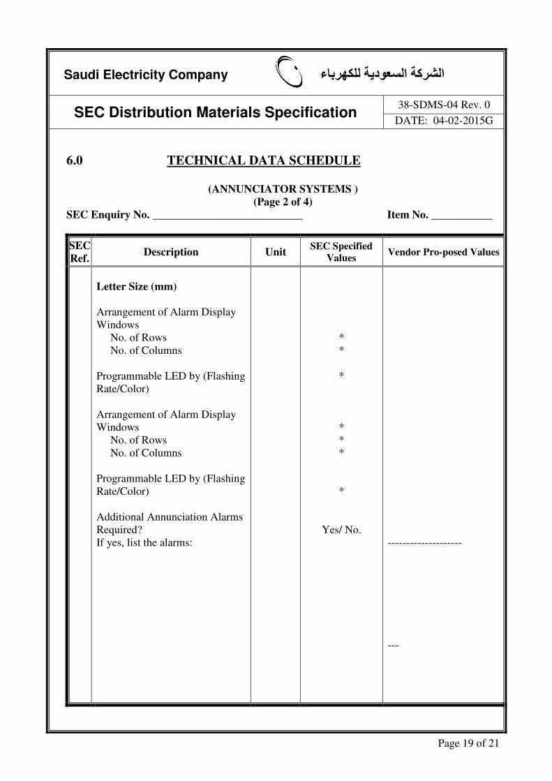
6.0 TECHNICAL DATA SCHEDULE
(ANNUNCIATOR SYSTEMS )
(Page 2 of 4)
SEC Enquiry No. ___________________________ Item No. ___________
SEC
Ref. Description Unit
SEC Specified
Values Vendor Pro-posed Values
Letter Size (mm)
Arrangement of Alarm Display
Windows
No. of Rows
No. of Columns
Programmable LED by (Flashing
Rate/Color)
Arrangement of Alarm Display
Windows
No. of Rows
No. of Columns
Programmable LED by (Flashing
Rate/Color)
Additional Annunciation Alarms
Required?
If yes, list the alarms:
*
*
*
*
*
*
*
Yes/ No.
--------------------
---

Saudi Electricity Company الشركة السعودية للكھرباء
SEC Distribution Materials Specification 38-SDMS-04 Rev. 0
DATE: 04-02-2015G
Page 20 of 21
6.0 TECHNICAL DATA SCHEDULE
(ANNUNCIATOR SYSTEMS)
(Page 3 of 4)
SEC Enquiry No. ___________________________ Item No. ___________
SEC
Ref. Description Unit
SEC Specified
Values
Vendor Pro-posed
Values
4.7 Power Supply Nominal DC
Voltage (V dc)
DC Voltage Range:
Minimum (V dc)
Maximum (V dc)
AC Backup Supply (V ac)
No. of Phases/Wires
Rated Frequency (Hz)
Frequency Variation Range:
5.0 TESTS
Optional or Special Test
Requirements, if any
60 Hz
± 5 %
-
* values to be proposed by vendors

Saudi Electricity Company الشركة السعودية للكھرباء
SEC Distribution Materials Specification 38-SDMS-04 Rev. 0
DATE: 04-02-2015G
Page 21 of 21
6.0 TECHNICAL DATA SCHEDULE
(ANNUNCIATOR SYSTEMS)
(Page 4 of 4)
SEC Enquiry No: ___________________________ Item No: ____________
A) Additional technical information or features specified by SEC.
B) Additional supplementary data or features proposed by Vendor/Supplier.
C) Other particulars to be filled up by Vendor/Supplier.
(Use separate sheet if needed).
Address Manufacturer Vendor/Supplier
Name of the Company
Location & Office Address
Authorized Name & Signature
Date
Official Seal / Stamp