355 precision absolute manometer operating instructions · file no. 355:440-1 355 precision...
TRANSCRIPT

File No. 355:440-1
355 PRECISION ABSOLUTE MANOMETEROPERATING INSTRUCTIONS
The Model 230-355Precision Absolute Manometeris a microprocessor basedpressure sensing device that canbe used to directly measureabsolute pressure. Models areavailable to measure pressureranges up to 900mm HgA and2000mm HgA. Pressure can bedisplayed in a variety ofengineering units. All unitsinclude a Tare function , a Min/Max function, selectable damprates and altitude displayed infeet or meters. The 355 can alsodisplay barometric pressurecorrected to sea level.
TABLE OF CONTENTS
Subject Page
Keypad functions ---------------------------------------------------- 2Zero Lockout---------------------------------------------------------- 3Pressure zeroing the manometer ----------------------------------- 4Program mode -------------------------------------------------------- 9Units select ------------------------------------------------------------ 9Displaying altitude -------------------------------------------------10Pressure corrected to Sea Level -----------------------------------13Damp rate select ----------------------------------------------------15Auto shut off --------------------------------------------------------16User info select -----------------------------------------------------17Contrast select ------------------------------------------------------19Connecting the pressure source -----------------------------------20Changing the battery------------------------------------------------20Recalibration---------------------------------------------------------21Specifications ------------------------------------ inside back cover
File No. 355:440-1
355 PRECISION ABSOLUTE MANOMETEROPERATING INSTRUCTIONS
Meriam Instrument’s 355Precision Absolute Manometeris a microprocessor basedpressure sensing device that canbe used to directly measureabsolute pressure. Models areavailable to measure pressureranges up to 900mm HgA and2000mm HgA. Pressure can bedisplayed in a variety ofengineering units. All unitsinclude a Tare function , a Min/Max function, selectable damprates and altitude displayed infeet or meters. The 355 can alsodisplay barometric pressurecorrected to sea level.
TABLE OF CONTENTS
Subject Page
Keypad functions ---------------------------------------------------- 2Zero Lockout---------------------------------------------------------- 3Pressure zeroing the manometer ----------------------------------- 4Program mode -------------------------------------------------------- 9Units select ------------------------------------------------------------ 9Displaying altitude -------------------------------------------------10Pressure corrected to Sea Level -----------------------------------13Damp rate select ----------------------------------------------------15Auto shut off --------------------------------------------------------16User info select -----------------------------------------------------17Contrast select ------------------------------------------------------19Connecting the pressure source -----------------------------------20Changing the battery------------------------------------------------20Recalibration---------------------------------------------------------21Specifications ------------------------------------ inside back cover

2
KEYPAD FUNCTIONS
ON/OFF & BACKSPACE KEYTurns the manometer on into the Measure Modeand then turns the unit off from the MeasureMode. Also serves as a backspace key whenediting in the Program Mode. The backspace
function takes the user out of a programmable registerwithout changing the previous setting. Pressing this keyrepeatedly will return the user to the Measure Mode andthen shut off the manometer.
MIN/MAX & UP ARROW KEYIn the Measure Mode activates the Min/Maxfunction of the manometer. When activated thethe minimum value is displayed on the upper leftof the display and the maximum value on theupper right. Min/Max values on the display are
updated every 0.1 seconds. This key also deactivates thisfunction. Up arrow key is used to scroll through theprogrammable registers when the unit is in the ProgramMode. Once a programmable register is selected the uparrow can be used to edit that register.
TARE & DOWN ARROW KEYIn the Measure Mode activates and deactivatesthe display TARE function. The Tare function isdesigned to set the displayed value to “0”. WithTARE activated, the letter “T” appears in thelower left of the display. Down arrow function
is used to scroll through programmable registers with theunit in the Program Mode. Once a programmable registeris selected the down arrow can be used to edit thatregister.
PRGM & ENTER KEYPuts the manometer into the Program Modefrom the Measure Mode. When in the ProgramMode, pressing this key selects theprogrammable register to be edited. After the
register has been edited, pressing the PRGM key enters thenew setting into the manometer’s non-volatile memory.This key also acts as a forward space key when editinguser input such as the header name.

3
Zero Lockout Operating Instructions
When enabled, the zero lockout feature isdesigned to help prevent operators from inad-vertently zeroing the unit during normal opera-tion. This feature is enabled when the 350Smart Manometer leaves the factory. To verifythis, press the ON/OFF button on the key pad toturn the unit on. After the initial headers aredisplayed the manometer should display a mes-sage indicating that the Zero Lockout feature isenabled. If this is not displayed, the lockoutfeature is disabled and the manometer can bezeroed if the applied pressure is at 1% of FullScale or less. To enable or disable the lockoutfeature follow these steps.
1. Start with the Smart Manometer off.2. Press and hold the PRGM key.3. While holding the PRGM key, press
the ON/OFF key to turn the unit on.4. Release both keys.5. If the lockout feature is enabled, it will be
disabled. If it was disabled, it will now be enabled. The current status can be verified by turning the unit off then back on again. A message will be displayed when the Zero Lockout feature is enabled.

4
PRESSURE ZEROING THE MANOMETER
Periodically, the 355 Smart Manometer should have a newzero taken. This is done to remove zero drift that hasoccurred since the manometer was last zeroed.
The 355 provides three mechanisms for re-zeroing.
1. Referenced to Absolute Zero: This traditionaland preferred method takes a “snapshot” of themeasured pressure when a vacuum of less than100 microns Absolute is applied to the sensor.
2. Factory Zero: This method restores the calibra-tion curve to the original zero taken at the fac-tory. Note that this feature is intended forcomparison purposes, and should not be used forreal pressure measurement, as any zero-drift willnot be compensated.
3. User-Adjusted Zero: This method allows theuser to enter any pressure value when a knownreference is applied (for example, the localbarometer). The manometer will compare itsactual measured value with the entered value,and calculate a new zero reference based on theoffset.

5
Keystroke Display
1. Press ON/OF button. The display briefly showsthe header name and fullscale range of the unit in thelast engineering units se-lected. The manometer thengoes into the MeasureMode where the appliedpressure and engineeringunit of measure are dis-played.
2. Connect the 355 toa vacuum sourcecapable of a vac-uum of 100 micronsabsolute pressure orless.
3. Pull a full vacuum. Display should read close tozero. (See note on nextpage)
4. Press MIN/MAXand TARE keys atthe same time. (Seefigure 1.)
Top line of display reads“ZEROING SOURCE:”Bottom line of display reads“REF TO ABS ZERO”
5. Press the PRGMkey.
Top line of display reads“ZERO IN PROGRESS”while bottom line countsdown from 9. Zeroing iscomplete when unit returnsto Measure Mode.
1. To zero the manometer with Referenced to AbsoluteZero, starting with the unit turned off, follow this keystrokesequence:
Figure 1
MIN/ MAX TARE

6
Keystroke Display
1. Press MIN/MAX andTARE keys at thesame time. (Seefigure 1.)
Top line of display reads“ZEROING SOURCE:”Bottom line of displayreads “REF TO ABSZERO”
2. Press up ↑ or down ↓arrow key until de-sired zero function isshown on the bottomline.
Bottom line of displayreads “FACTORY ZERO”
3. Press the PRGM key. Zeroing is complete whenunit returns to MeasureMode.
Note: The 355 can be zeroed only if the new Zero iswithin ± 1% FS of the original factory calibration zero.If outside this limit a “ZERO RANGE ERROR” messageappears and the manometer will not zero.
2. To zero the manometer with Factory Zero, startingwith the unit in normal measure mode, follow this keystroke sequence:

7
Keystroke Display
1. Apply a known, ac-curate pressuresource. This may betrue atmosphericpressure, with knownreference defined bya local barometer.
2. Press MIN/MAX andTARE keys at thesame time. (Seefigure 1.)
Top line of display reads“ZEROING SOURCE:”
Bottom line of displayreads “REF TO ABSZERO”
3. Press up ↑ or down ↓arrow key until de-sired zero function isshown on the bottomline.
Bottom line of displayreads “USER ADJ.ZERO”
4. Press the PRGM key. Top line of display showsthe current non-zero com-pensated pressure value.Bottom line of displayshows the same value,along with the engineeringunit.
5. Press any of up ↑ ordown ↓ arrow key orthe PRGM key tobegin editing.
Top line of display contin-uously updates. Bottomline of display data isfrozen, and the first digit isblinking.
Example: set currentpressure value to 29.5InHg.
To zero the manometer with User-Adjusted Zero, startingwith the unit in normal measure mode, follow this keystroke sequence:

8
Note that the User Adjusted Zero feature will not acceptentries in altitude units (FEET or METERS). When thecurrent engineering unit is FEET, the User Adjusted Zerofunction will automatically prompt for an entry in Inchesof Mercury. When the current engineering unit is ME-TERS, the User Adjusted Zero function will automaticallyprompt for an entry in Millimeters of Mercury.
6. Press the UP↑ orDOWN↓ arrow keyto set the first digit to0.
Current: xxx.xx0xx.xx INHG
Using the UP↑ arrowkey the charactersequence is 0 - 9, (-)negative, (.) decimalpoint. The (-)sign isused if your locationis below sea level.
7. When the digit iscorrect press thePRGM key.
Cursor flashes to the rightof “0”.
If an error is madeuse the back space ←key to move the cur-sor back to the incor-rect digit. Press theUP↑ or DOWN ↓arrow keys to displaythe correct value.
8. Continue this processuntil the displayreads as shown atright.
Current: xxx.xx029.50 INHG
9. Press the PRGM keyto enter the finaldigit.
Zeroing is complete whenunit returns to MeasureMode.

9
PROGRAM MODE
The Program Mode is used to configure the manometerfor Measure Mode operation. The configurable registersthat are found in the Program Mode are Units Select,Damp Rate Select, User Info Select, Contrast Select, SeaLevel Select and Exit. The manometer can be put into theProgram Mode at any time during Measure Modeoperation by pressing the PRGM key. The top line of thedisplay will read “PROGRAM MODE”. The bottom linewill read “UNITS SELECT”. Press the up or down arrowkeys to scroll through the Program Mode to the desiredregister.
UNITS SELECT
The standard engineering units available on the SmartManometer are:
1. Inches of Mercury at 0° Celsius2. Millimeters of Mercury at 0° Celsius3. PSI4. Millibars5. Bars6. Kilo Pascals7. Torrs8. Feet (altitude see page 5)9. Meters (altitude see page 5)
To change engineering unit of measure the manometershould be “ON” and in the Measure Mode. Then followthese steps:
Keystroke
1. Press PRGM key.
2. Press PRGM key
Display
PROGRAM MODEUNITS SELECT
UNITS SELECT bottom shows current
engineering units

10
3. Press up or down arrow key until desired engineering unit is displayed.
4. Press the PRGM key to select engineering unit.
5. Press the down arrow key.
6. Press PRGM key.
Engineering units on bottomline of display change.
PROGRAM MODEUNITS SELECT
PROGRAM MODEEXIT
Display returns to MeasureMode in new engineeringunits.
DISPLAYING ALTITUDE
The model 355 is capable of displaying altitude in feet ormeters. The operator can chose between displaying altitudebased on U.S. Standard Atmosphere of 1962 tables or analtitude entered by the user. The user defined altitude canbe taken from maps or survey trig markers. To set thealtitude based on U.S. Standard of 1962 use the followingsteps:
Keystroke
1. In the Measure Mode press the PRGM key.
2. Press PRGM key.
3. Press the UP or DOWN arrow key until the second line of the display reads “FEET” or “METERS”.
4. Press the PRGM key.
Display
PROGRAM MODEUNITS SELECT
UNITS SELECTcurrent engineering units on
the bottom line.
UNITS SELECTbottom line reads FEET or
METERS
ALTITUDE SELECTSTANDARD

11
5. Press the PRGM key to display altitude based on the U.S. Standard Atmosphere of 1962
6. Press the UP arrowkeys to set altitude manually.
7. Press the PRGM key.
8. If the value is the correct altitude, press the PRGM key.
If the value is not the correct altitude, press the UP arrow key.
9. Press the PRGM key
Example: set altitude to 685 feet above sea level.
10. Press the UP or DOWN arrow key to set the first digit to 6.
PROGRAM MODEUNITS SELECT
ALTITUDE SELECTREF. TO USER
VALUE=: 00000000CHANGE?: NO
PROGRAM MODEUNITS SELECT
Press the backspace keyto return to the MeasureMode.
VALUE=: 00000000CHANGE?: YES
USER MODE-FEET 00000000
USER MODE-FEET 60000000
If the U.S. Standard Atmosphere tables are desired, press-ing the Backspace key at this point returns the unit tothe Measure Mode.
USER DEFINED ALTITUDE:To display altitude based on user entered infor-mation, follow steps 1 - 3 on page 5. Skip step4 and proceed to step 6 below.

12
To set the unit to read in meters, select METERS from theUNITS SELECT menu. Then follow the same steps asoutlined on pages 10 and 11.
Because the local barometer changes all the time, theUSER MODE altitude must be reentered each time the 355is to be used in this mode. To adjust the unit to the currentbarometric pressure without changing the base altitudeselect NO (page 11 , step 6) by pressing the PRGM key.The 355 will now display the current altitude. To maximizeaccuracy the local altitude should be reset whenever betteraltitude information is available.
Using the UP arrow key the character sequence is 0 - 9, ( - ) negative, (.) decimal point. The ( - )sign is used if your location is below sea level.
11. When the digit is correct press the PRGM key.
If an error is made use the back space key to move the cursor back to the incorrect digit. Press the up or down arrow keys to display the correct value.
12. Continue this process until the display reads as shown at right.
13. Press the PRGM key to enter the final digit.
14. Press the backspace key to return to the measure mode.
Cursor flashes to the right of“6”.
USER MODE-FEET 685.0000
PROGRAM MODEUNITS SELECT
Second line of the displayreads: U 685 FEET

13
PRESSURE CORRECTED TO SEA LEVEL
Pressure reduction to Sea Level is required so that baro-metric readings can be compared at different elevations.The correction to sea level is done using a “hypsometricequation”. This equation simulates a “fictitous column ofair” which extends downward from the instruments loca-tion to sea level. This fictitous column is assumed to besimilar to the actual air column over nearby lower eleva-tions. Some properties are related to observed conditionswhile others must be assumed. Barometric pressures givenby the National Weather Service and used at airports arealways corrected to to sea level.
To set the unit to display pressure corrected to sea level:
Keystrokes1. Determine the elevation
of the instrument above sea level, in meters. 700 meters will be used as an example.
2. In the Measure Mode press the PRGM key.
3. Press the UP arrow key four times.
4. Press the PRGM key.
5. Press the UP or DOWN arrow key to set the correction to sea level status.
6. To turn on the correction set ENABLED on the second line and press the PRGM key. To turn it off set DISABLED on the line and go to step 12.
Display
PROGRAM MODEUNITS SELECT
PROGRAM MODESEA LEVEL SELECT
SEA LEVEL SELECTsecond line will read EN-ABLED or DISABLED.
Second line toggles betweenENABLED and DIS-ABLED.
VALUE=: 00000000CHANGE?: NO

14
7. To change the value press the UP arrow key to toggle the display.
8. Press the PRGM key.
9. Press the UP or DOWN arrow keys to set the correct value in the first digit.
10. When the value is correct press the PRGM key.
11. Repeat steps 9 and 10 until the correct elevation is entered.
12. Press the PRGM key to continue moving the cursor to the right. When the last digit is entered the unit will leave the sea level select mode and return to the Program Mode.
13. Press the backspace key. The display will return to the Measure Mode. If correction to sea level is enabled, the display will have the letter S at the beginning of the second line.
VALUE=: 00000000CHANGE?: YES
SEA LEVEL METERS00000000
SEA LEVEL METERS70000000
Cursor moves over the nextdigit.
SEA LEVEL METERS700.0000
PROGRAM MODEUNITS SELECT
S 803.1 TORR

15
DAMP RATE SELECT
Adjustable damping is available to steady the display whenmeasuring pulsating pressure or flow. The SmartManometer has a range of damping rates of 0.1, 0.2, 0.5, 1,2, 5, 10, and 25 seconds. Damping is done by averagingnew data from the pressure sensor against previouslycollected data. The microprocessor collects data from thesensor every 0.1 seconds. The display updates every 0.5seconds, showing the current 0.1 second pressure reading.When set at 25 seconds, the display updates every 0.5seconds with the average of the previous 25 secondsreadings. Therefore, it takes up to 25 seconds from thetime pressure is applied until the manometer displays thefull scale applied pressure. Min/Max display updates every0.1 seconds.
To set the damp rate:
Keystroke
1. Follow steps on page 4 toput the unit in Program Mode.
2. Press the up arrow key.
3. Press the PRGM key.
4. Press the up or down arrow keys until the desired damp rate is displayed on bottom line.
5. Press the PRGM key.
6. Press the down arrow key.
7. Press the PRGM key.
Display
PROGRAM MODEUNITS SELECT
Bottom line readsDAMP RATE SELECT
Top line readsDAMP RATE SELECT
Bottom line shows damprate in seconds.
PROGRAM MODEUNITS SELECT
Bottom line reads “EXIT”.
Returns to Measure Mode.
16
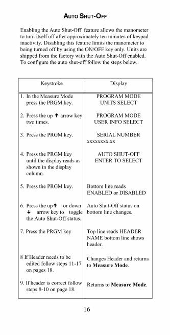
Enabling the Auto Shut-Off feature allows the manometerto turn itself off after approximately ten minutes of keypadinactivity. Disabling this feature limits the manometer tobeing turned off by using the ON/OFF key only. Units areshipped from the factory with the Auto Shut-Off enabled.To configure the auto shut-off follow the steps below.
AUTO SHUT-OFF
Keystroke
1. In the Measure Mode press the PRGM key.
2. Press the up arrow key two times.
3. Press the PRGM key.
4. Press the PRGM key until the display reads as shown in the display column.
5. Press the PRGM key.
6. Press the up or down arrow key to toggle
the Auto Shut-Off status.
7. Press the PRGM key
8 If Header needs to be edited follow steps 11-17 on pages 18.
9. If header is correct follow steps 8-10 on page 18.
Display
PROGRAM MODEUNITS SELECT
PROGRAM MODEUSER INFO SELECT
SERIAL NUMBERxxxxxxxx.xx
AUTO SHUT-OFFENTER TO SELECT
Bottom line readsENABLED or DISABLED
Auto Shut-Off status onbottom line changes.
Top line reads HEADERNAME bottom line showsheader.
Changes Header and returnsto Measure Mode.
Returns to Measure Mode.
16
Enabling the Auto Shut-Off feature allows the manometerto turn itself off after approximately ten minutes of keypadinactivity. Disabling this feature limits the manometer tobeing turned off by using the ON/OFF key only. Units areshipped from the factory with the Auto Shut-Off enabled.To configure the auto shut-off follow the steps below.
AUTO SHUT-OFF
Keystroke
1. In the Measure Mode press the PRGM key.
2. Press the up arrow key two times.
3. Press the PRGM key.
4. Press the PRGM key until the display reads as shown in the display column.
5. Press the PRGM key.
6. Press the up or down arrow key to toggle
the Auto Shut-Off status.
7. Press the PRGM key
8 If Header needs to be edited follow steps 11-17 on pages 18.
9. If header is correct follow steps 8-10 on page 18.
Display
PROGRAM MODEUNITS SELECT
PROGRAM MODEUSER INFO SELECT
SERIAL NUMBERxxxxxxxx.xx
AUTO SHUT-OFFENTER TO SELECT
Bottom line readsENABLED or DISABLED
Auto Shut-Off status onbottom line changes.
Top line reads HEADERNAME bottom line showsheader.
Changes Header and returnsto Measure Mode.
Returns to Measure Mode.

17
USER INFO SELECT
The User Info Select register is designed to provide theuser with information on the hardware and software in themanometer. This register stores information on the sensor’sserial number, software version, date of last calibration,Auto Shut-Off status and the instrument Start-Up Header.The Start Up Header appears whenever the manometer isturned on. Below the Header is the Full Scale of themanometer, in the last engineering units programmed. Thefactory setting of the header is “NOVALYNX CORP”. Thiscan be edited to show a custom alpha-numeric string asrequired by the user.To configure the Unit Info Select register follow thekeystrokes listed below.
Keystroke
1. From the Measure Mode, press the PRGM key
2. Press the up arrow key two times.
3. Press the PRGM key.
4. Press the PRGM key.
5. Press the PRGM key.
6. Press the PRGM key.
7. Instructions for setting the AUTO SHUT-OFF are on page 16. Press up
arrow key to proceed to editing the Header.
Display
PROGRAM MODEUNITS SELECT
Bottom line changes to“USER INFO SELECT”
Bottom line shows serialnumber.
Software version numbershown.
Calibration Date shown.
AUTO SHUT OFFENTER TO SELECT
HEADER NAMENOVALYNX CORP
17
USER INFO SELECT
The User Info Select register is designed to provide theuser with information on the hardware and software in themanometer. This register stores information on the sensor’sserial number, software version, date of last calibration,Auto Shut-Off status and the instrument Start-Up Header.The Start Up Header appears whenever the manometer isturned on. Below the Header is the Full Scale of themanometer, in the last engineering units programmed. Thefactory setting of the header is “MERIAM INSTR.”. Thiscan be edited to show a custom alpha-numeric string asrequired by the user.To configure the Unit Info Select register follow thekeystrokes listed below.
Keystroke
1. From the Measure Mode, press the PRGM key
2. Press the up arrow key two times.
3. Press the PRGM key.
4. Press the PRGM key.
5. Press the PRGM key.
6. Press the PRGM key.
7. Instructions for setting the AUTO SHUT-OFF are on page 16. Press up
arrow key to proceed to editing the Header.
Display
PROGRAM MODEUNITS SELECT
Bottom line changes to“USER INFO SELECT”
Bottom line shows serialnumber.
Software version numbershown.
Calibration Date shown.
AUTO SHUT OFFENTER TO SELECT
HEADER NAMEMERIAM INSTR

18
8. If header is correct press backspace key . If editing is desired proceed to step 11.
9. Press up arrow key two times.
10. Press the PRGM key.
11. Press the up or down arrow keys to set
correct alpha-numeric value.
12. Press right arrow to accept entry.
13. Repeat steps 11 and 12 until the desired Header is shown.
14. If an error is noted press the back arrow key until cursor is over the incorrect value. Follow step 11 to correct. Press the right arrow to advance the cursor without changing values.
14. When header is complete press the PRGM key to advance cursor to end of bottom line.
15. Press the PRGM key.
16. Press down arrow key
17. Press the PRGM key.
PROGRAM MODEUSER INFO SELECT
Bottom line reads “EXIT”.
Returns to Measure Mode.
Displays a number between0 and 9, a letter from A to Z,/ or a blank space.
Cursor advances one spaceto right.
Cursor flashes at bottomright.
PROGRAM MODEUNITS SELECT
Bottom line reads “EXIT”.
Returns to Measure Mode.
19
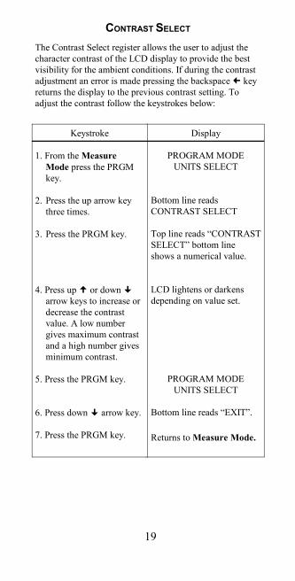
CONTRAST SELECT
The Contrast Select register allows the user to adjust thecharacter contrast of the LCD display to provide the bestvisibility for the ambient conditions. If during the contrastadjustment an error is made pressing the backspace keyreturns the display to the previous contrast setting. Toadjust the contrast follow the keystrokes below:
Display
PROGRAM MODEUNITS SELECT
Bottom line readsCONTRAST SELECT
Top line reads “CONTRASTSELECT” bottom lineshows a numerical value.
LCD lightens or darkensdepending on value set.
PROGRAM MODEUNITS SELECT
Bottom line reads “EXIT”.
Returns to Measure Mode.
Keystroke
1. From the Measure Mode press the PRGM key.
2. Press the up arrow key three times.
3. Press the PRGM key.
4. Press up or down arrow keys to increase or decrease the contrast value. A low number gives maximum contrast and a high number gives minimum contrast.
5. Press the PRGM key.
6. Press down arrow key.
7. Press the PRGM key.
19
CONTRAST SELECT
The Contrast Select register allows the user to adjust thecharacter contrast of the LCD display to provide the bestvisibility for the ambient conditions. If during the contrastadjustment an error is made pressing the backspace keyreturns the display to the previous contrast setting. Toadjust the contrast follow the keystrokes below:
Display
PROGRAM MODEUNITS SELECT
Bottom line readsCONTRAST SELECT
Top line reads “CONTRASTSELECT” bottom lineshows a numerical value.
LCD lightens or darkensdepending on value set.
PROGRAM MODEUNITS SELECT
Bottom line reads “EXIT”.
Returns to Measure Mode.
Keystroke
1. From the Measure Mode press the PRGM key.
2. Press the up arrow key three times.
3. Press the PRGM key.
4. Press up or down arrow keys to increase or decrease the contrast value. A low number gives maximum contrast and a high number gives minimum contrast.
5. Press the PRGM key.
6. Press down arrow key.
7. Press the PRGM key.

20
The manometer is powered by one 9 volt battery. When theoutput of the battery under load drops below 6.5 volts thedisplay will alternate between “LOW POWER DETECT”and “REPLACE BATTERY”.
To replace the battery locate the battery compartment inthe bottom rear of the manometer. Push down on the smallrectangular area in the battery cover. While pushing thecover down, slide the cover out the bottom of the unit. Pullthe battery connector off the battery terminals. Plug thenew battery into the connector and install in thecompartment. Slide the battery cover on until the lockingclip goes into the manometer housing and the channels onthe bottom of the cover are locked in place.
CHANGING THE BATTERY
CONNECTING THE PRESSURE SOURCE
The 355 Precision Absolute Manometer comes with a316ss, 1/8” FNPT pressure port. The manometer should beheld firmly in one hand while a small wrench is used totighten the 1/8” MNPT connection into the manometerspressure port. DO NOT USE the large nut holding thepressure connection in the bulkhead in the manometer tohold the manometer while the pressure connection is in-stalled. If the bulkhead nut is loosened it is possible for thesensor and sensor board to turn inside the manometer body.This can damage the sensor board.

21
RECALIBRATION
The Smart Manometer’s accuracy can be verified by usinga ± 0.015% of reading absolute deadweight tester. It isrecommended that the manometer be checked at aminimum of four test points at 25%, 50%, 75% and 100%of the units range. A full ten point evaluation provides themost complete information on the manometersperformance.
Before performing the evaluation there are severalcorrections to the deadweight tester that may have to bemade.
1. Use the User Unit Select option in Program Mode tomatch the Smart Manometer units to the deadweight testerunits. Be sure to match the Smart Manometer temperaturereference to the temperature reference of the deadweighttester (for in.H2O and Hg units only).
2. Correct the deadweight tester readings for ambienttemperature if it is different from the referencetemperature. The Smart Manometer does thisautomatically.
3. The local gravity at location where the evaluation isbeing performed must be corrected for on the deadweighttester. Standard gravity reference is 980.665 cm/sec/sec.This gravity occurs at 45° north latitude, at sea level.
4. Make sure there are no leaks in the system.
The mm Hg absolute manometer references mercury at0°C. The effects of local gravity on the Smart Manometerare corrected for by zeroing the manometer (see pgs. 3 &4) before the evaluation.
This evaluation will confirm whether the manometer is oris not operating within its accuracy specification.

22
If the manometer is outside of it’s accuracy limits, it mustbe returned to the factory for recalibration. The SmartManometer cannot be recalibrated in the field. Ifrecalibration is required, contact NovaLynx at thenumbers listed below for a Return Authorization(RA) number.
NovaLynx CorporationPO Box 240Grass Valley, CA 95945 (530) 823-7185 Phone(530) 823-8997 [email protected] All Smart Manometers recalibrated at the factory arereturned with certificates of NIST traceability.
22
If the manometer is outside of it’s accuracy limits, it mustbe returned to the factory for recalibration. The SmartManometer cannot be recalibrated in the field. Ifrecalibration is required, contact the Meriam Instrumentrepresentative in your area or call the factory at thenumbers listed below for a Return Material Authorization(RMA) number.
Meriam Instrument10920 Madison Ave.Cleveland, OH 44102
Ph. (216) 281-1100FAX (216) 281-0228
All Smart Manometers recalibrated at the factory arereturned with certificates of NIST traceability.

SPECIFICATIONS
Sensor Type and Range:AI2000: Absolute Isolated 2000 mm HgAI0900: Absolute Isolated 900 mm Hg
Accuracy:355-AI0900: ±0.02 % F.S. (F.S. = 900 mm Hg)355-AI2000: ±0.015 % F.S.* from 0-1000 mm Hg
±0.025% F.S.* from 1000-2000 mm Hg *F.S. = 2000 mm Hg Absolute
Includes the combined effects of temperature, linearity, repeatability, hysteresis and resolution. NIST certification supplied with manometer.
Temperature:Storage: -40° F to 140° F (-40° C to 60° C)Operating: -4° F to 122° F (-20° C to 50° C)
Media Compatibility:Isolated sensors for all fluids compatible with 316SS.
Pressure Limits:4000 mm Hg Absolute (AI0900 and AI2000)
Connection: 1/8” female NPT, 316SS.
Power: 9 volt battery, lithium or alkaline, field replaceable.Lithium is recommended for operation below 32° F (0° C).
Display: 5 significant digit LCD
Enclosure: 14 oz. ABS plastic (6.5” × 3.6” × 2,25”)
CSA units: Intrinsically safe for Class 1, Groups A, B, C,and D.