35 coordinated design of a mb-pss and statcom controller to enhance power system stability · ·...
TRANSCRIPT

International Journal of Electrical Engineering and Technology (IJEET), ISSN 0976 –
6545(Print), ISSN 0976 – 6553(Online) Volume 3, Issue 2, July- September (2012), © IAEME
352
COORDINATED DESIGN OF A MB-PSS AND STATCOM
CONTROLLER TO ENHANCE POWER SYSTEM STABILITY
1Gaber Shabib, and
2Youssef A. Mobarak
1Faculty of Energy Engineering, Aswan University, Egypt [email protected]
2Electrical Engineering Department, Faculty of Engineering, Rabigh, King Abdulaziz
University, Saudi Arabia, [email protected]
ABSTRACT
This paper solves the problem of power system stabilization by using the advanced static synchronous
shunt compensator STATCOM to increase the damping of electromechanical oscillations of the
power system and regulates the system voltage by absorbing or generating reactive power to the
system. Also, a multi-band power system stabilizer MB-PSS is developed in this paper to get a
moderate phase advance at all frequencies of interest in order to compensate for the inherent lag
between the field excitation and the electrical torque induced to ensure robust oscillation damping. A
combined control of STATCOM with MB-PSS is proposed also in this paper to give more increase of
the oscillation damping that improves power system stability. The application of these controllers is
applied to the multi-machine two-area power system using Matlab Toolbox.
Keywords: STATCOM, MB-PSS, Power System Stability, Oscillation Damping.
Nomenclature
ψd, ψq direct and quadrature axis component of stator flux
ed, eq direct and quadrature axis component of stator voltage
id, iq direct and quadrature axis component of stator current
rs stator resistance
Ed’, Eq
’ direct and quadrature axis transient voltage
ψkd, ψkq direct and quadrature axis damper flux linkage
Efd exciter voltage
KG speed governor gain
D the percentage of steady-state speed regulation or unit droop
TV the time constant of the vessel steam flow
P0 the steady-state vessel pressure
Q0 the steady-state mass flow out of the vessel
Vvessel the volume of the vessel
Kvessel the density change due to pressure changes in constant temperature
vsteam the specific volume of steam
T0 the vessel temperature
P2 ,P1 the boundaries of the smallest pressure interval
INTERNATIONAL JOURNAL OF ELECTRICAL ENGINEERING &
TECHNOLOGY (IJEET)
ISSN 0976 – 6545(Print)
ISSN 0976 – 6553(Online)
Volume 3, Issue 2, July – September (2012), pp. 352-372
© IAEME: www.iaeme.com/ijeet.html
Journal Impact Factor (2012): 3.2031 (Calculated by GISI)
www.jifactor.com
IJEET
© I A E M E

International Journal of Electrical Engineering and Technology (IJEET), ISSN 0976 –
6545(Print), ISSN 0976 – 6553(Online) Volume 3, Issue 2, July- September (2012), © IAEME
353
v2 , v1 the specific volumes
PX the power of turbine X
K the turbine stage between draining points
Qk the mass flow in stage k
hink the inlet steam enthalpy of stage in k
houtk the outlet steam enthalpy of stage k
Xt a leakage reactance
m he modulation ratio defined by pulse width modulation (PWM)
K the ratio between the ac and dc voltage depending on the converter structure
Vdc the dc voltage
ψ the phase defined by PWM
Cdc the dc capacitor value
Idc the capacitor current
isd, isq the d- and q-components of the STATCOM current Is
Tdo’, Tdo
” transient and subtransient direct axis time constants (in sec.)
Tqo’, Tqo
” transient and subtransient quadrature axis time constants (in sec.)
TSR TSM the speed governor and servomotor time constants
xd, xd’, xd
” synchronous, transient and subtransient direct-axis reactances
xq, xq’, xq
” synchronous, transient and subtransient quad.- axis reactances
c1, c2, c3 constant
Kpac, Kiac Kpdc, Kidc ac and dc voltages proportional and integral gains
Cv-open,Cv-close,Copen,Cclose the valve’s rate limits and position limits
TSC,TRH1, TRH2,TCO steam chest, first reheater, second reheater, and crossover time constants
FVHP, FHP, FIP , FLP very-high-pressure (VHP), HP, IP, and LP turbines’ power fractions
PHP, PIP, PLP the HP turbine power, IP turbine power, and LP turbine power
1. INTRODUCTION Since 1960s, low frequency oscillations have been observed when large power systems are
interconnected by relatively weak tie lines. These oscillations may sustain and grow to cause
system separation if no adequate damping is available [1-5]. Nowadays, the conventional
power system stabilizer CPSS is widely used by power system utilities. Generally, it is
important to recognize that machine parameters change with loading make the machine
behavior quite different at different operating conditions. Since these parameters change in a
rather complex manner, a set of stabilizer parameters, which stabilizes the system under a
certain operating condition, may no longer yield satisfactory results when there is a drastic
change in power system operating conditions and configurations. Hence, power system
stabilizers PSSs should provide some degree of robustness to the variations in system
parameters, loading conditions, and configurations. H∞ optimization techniques [2] have been
applied to robust PSS design problem. However, the importance and difficulties in the
selection of weighting functions of H∞ optimization problem have been reported. In addition,
the additive and/or multiplicative uncertainty representation cannot treat situations, where a
nominal stable system becomes unstable after being perturbed [3]. Moreover, the pole-zero
cancellation phenomenon associated with this approach produces closed loop poles whose
damping is directly dependent on the open loop system [4].
On the other hand, the order of the H∞-based stabilizer is as high as that of the plant. This
gives rise to complex structure of such stabilizers and reduces their applicability. Kundur et
al. [4] have presented a comprehensive analysis of the effects of the different CPSS
parameters on the overall dynamic performance of the power system. It is shown that the
appropriate selection of CPSS parameters results in satisfactory performance during system
upsets. In addition, Gibbard [5] demonstrated that the CPSS provide satisfactory damping
performance over a wide range of system loading conditions. Robust design of CPSSs in
International Journal of Electrical Engineering and Technology (IJEET), ISSN 0976 –
6545(Print), ISSN 0976 – 6553(Online) Volume 3, Issue 2, July- September (2012), © IAEME
354
multi-machine power systems using genetic algorithm is presented in Ref. [6-7], where
several loading conditions are considered in the design process. Although PSSs provide
supplementary feedback stabilizing signals, they suffer a drawback of being liable to cause
great variations in the voltage profile and they may even result in leading power factor
operation under severe disturbances [8-9]. MB-PSS is based on multi-frequency variables
that this stabilizer can obtain to cope with all low, intermediate, and high frequencies
oscillations [10, 11]. The MB-PSS is developed in such a manner that it can be capable of
introducing moderate phase advance at all oscillations frequencies of interest in order to
compensate for the inherent lag between the field excitation and the electrical torque [7].
The recent advances in power electronics have led to the development of the flexible
alternating current transmission systems FACTS. Generally, a potential motivation for the
accelerated use of FACTS devices is the deregulation environment in contemporary utility
business. Along with primary function of the FACTS devices, the real power flow can be
regulated to mitigate the low frequency oscillations and enhance power system stability.
Recently, several FACTS devices have been implemented and installed in practical power
systems [12]. In the literature, a little work has been done on the coordination problem
investigation of excitation and FACTS-based stabilizers. Refs. [13-17] present a coordinated
PSS and SVC control for a synchronous generator. However, the proposed approach uses
recursive least squares identification, which reduces its effectiveness for on-line applications.
Rahim and Nassimi [15] presented optimum feedback strategies for both SVC and exciter
controls. However, the proposed controller requires some or all states to be measurable or
estimated. Moreover, it leads to a centralized controller for multi-machine power systems,
which reduces its applicability and reliability. Noroozian and Anderson [16] presented a
comprehensive analysis of damping of power system electromechanical oscillations using
FACTS, where the impacts of transmission line loading and load characteristics on the
damping effect of these devices have been discussed. Wang and Swift [12] have discussed
the damping torque contributed by FACTS devices, where several important points have been
analyzed and confirmed through simulations. However, all controllers were assumed
proportional and no efforts have been done towards the controller design.
On the other hand, it is necessary to measure the electromechanical mode controllability in
order to assess the effectiveness of different controllers and form a clear inspiration about the
coordination problem requirements [10, 13]. A comprehensive study of the coordination
problem requirements among PSSs and different FACTS devices has been presented in Refs
[18-21]. However, no efforts have been done towards the coordinated design of the stabilizers
investigated. By controlling the magnitude of the STATCOM voltage the reactive power
exchanges between the STATCOM and the transmission line [22-26]. One of the most
important advantages of the STATCOM is its behaviour during the voltage collapse at the
bus where it is located as it supplies almost a constant reactive power without being affected
by voltage variation across it. So far, conventional power system stabilizer PSS is still used as
an effective and economical facility to tackle the problem [14]. Many techniques have been
reported in the literature on the topic of coordinated design of PSS [27-31].
In this paper, a comprehensive assessment of the effects of the excitation and STATCOM
control when applied independently and also through coordinated application has been
carried out. Also, MB-PSS is developed in this paper to get a moderate phase advance at all
frequencies of interest in order to compensate for the inherent lag between the field excitation
and the electrical torque induced to ensure robust oscillation damping. A combined control of
STATCOM with MB-PSS is proposed also in this paper to give more increase of the
International Journal of Electrical Engineering and Technology (IJEET), ISSN 0976 –
6545(Print), ISSN 0976 – 6553(Online) Volume 3, Issue 2, July- September (2012), © IAEME
355
oscillation damping that improves power system stability. All these controllers are supplied
to the multi-machine two-area power system.
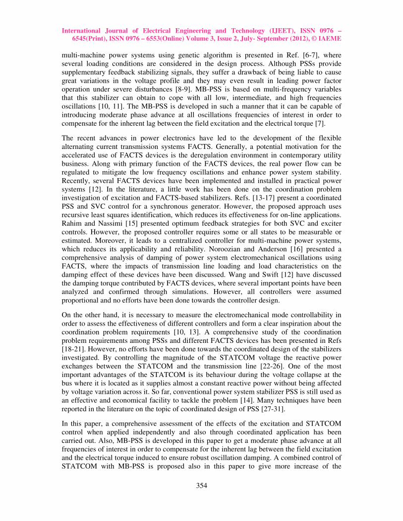
2. STUDIED SYSTEM AND MODELING
The studied system (Kundur's four-machine two-area test system) consists of two fully
symmetrical areas linked together by two 230 kV lines of 220 km length as shown in
Fig. (1). Despite its small size, it mimics very closely the behavior of typical systems
in actual operation [4]. Each area is equipped with two identical round rotor
generators rated 20kV/900MVA. The synchronous machines have identical
parameters [11], except for inertias which are H=6.5s in area 1 and H=6.175s in area
2. The parameters of the generators, turbines and exciters data are given in Appendix.
Thermal plants having identical speed regulators are further assumed at all locations,
in addition to fast static exciters with a gain on 200 [10]. The load is represented as
constant impedances and is split between the areas in such a way that area 1 is
exporting 413MW to area 2. Since the surge impedance loading of a single line is
about 140 MW, the system is somewhat stressed, even in steady-state.
Fig. 1: Single line diagram of four-machine two-area test system.
2.1. Power System Model
2.1.1 Generator:
The generator is represented by the sixth-order model comprising of the
electromechanical swing equation and the generator internal voltage equation [10-11].
The dynamics of rotor angle δ and velocity ω is described by the so called swing
equations:
( )ωω
∆−−=∆
DTTHdt
dem
2
1 (1)
∆ωωdt
dδo
= (2)
G1
G2 G4
1
5
6
2 11 12
9 10
4
8
7
3
20/230
0.0167
20/230
0.0167 20/230
0.0167
R=0.0025
X=0.0250
B/2=0.0437
R=0.0025
X=0.0250
B/2=0.043
R=0.001
X=0.010
B/2=0.0175
R=0.001
X=0.010
B/2=0.0175
R=0.011
X=0.110
B/2=0.19
25
R=0.0
X=0.005
R=0.0
X=0.005
Load A
967MW+j100MVAR
Qc=200MVAR
Load B
1767MW+j100MVAR
Qc=350MVAR
230KV, 220Km
G3
20/230
0.0167
Area 1
H=6.5
Area 2
H=6.175
STATCOM

International Journal of Electrical Engineering and Technology (IJEET), ISSN 0976 –
6545(Print), ISSN 0976 – 6553(Online) Volume 3, Issue 2, July- September (2012), © IAEME
356
where: ∆ω=ω-ωo is the deviation, in rad/s of rotor angular velocity from synchronous
velocity ωo=2πf, H is the p.u. inertia constant, Tm and Te are the p.u. mechanical and
electromagnetic torque, respectively, D is the damping coefficient. Figure (2) shows
the electrical model of the synchronous machine in the d-q frame.
The sixth order model is frequently employed in stability and control analysis. Its
stator transients (ψ˙d, ψ˙q) are considered so fast as to be negligible as far as transient
stability and its associated slow rotor oscillations, are concerned.
Fig. 2: Electrical model of the synchronous machine (q-d frame)
The following differential equations used to describe the electrical variables and the
two swing equations (1), (2) to describe the mechanical motion [4]. Two of the six
differential equations are used to describe the d and q axis components of the stator
fluxes as follows:
dsqd irψe0 ++= (3)
qsdq irψe0 +−= (4)
Four differential equations are required to describe rotor electrical dynamics in the
four windings assumed to be lying on the rotor.
( )( )( )
−′
′−−′′−
−′
′−′′−′+
−′
′−′′−′′−′−
′=′
2ld
ddldd2
ld
ddddkd2
ld
ddddqqfd
do
qxx
xxxxi
)xx(
)x)(xxx(ψ
)xx(
)x)(xxx(EEE
T
1E& (5)
( )( )( )
−′
′−−′′+
−′
′−′′−′−
−′
′−′′−′′+′−
′=′
2lq
qqlqq2
lq
qqqqkq2
lq
qqqqdd
qo
dxx
xxxxi
)xx(
)x)(xxx(ψ
)xx(
)x)(xxx(EE
T
1E& (6)
( )[ ]dldqkddo
kd ixxEψT
1ψ −′−′+−
′′=& (7)
( )[ ]qlqdkqqo
kq ixxEψT
1ψ −′−′−−
′′=& (8)
The following algebraic equations:
ddld
ddkd
ld
ldqd ix
xx
xxψ
xx
xxEψ ′′−
−′
′′−′+
−′
−′′′= (9)
qqlq
qqkq
lq
lqdq ix
xx
xxψ
xx
xxEψ ′′−
−′
′′−′+
−′
−′′′−= (10)
Which relate internal voltages and fluxes with output stator currents, along with the
following relationship for the electromagnetic torque:
+
+ +
R'kq2
R'kq1
L'1kq1
Rs
-
-
-
+
+
- ωR ψd L1
iq Vq Lmq
q axis
i'kq1
i'kq
V'kq1
V'kq2
L'1kq2
R'kd
Rs
-
-
-
+
- + ωR ψq L1
id Vd Lmd
d axis
i'kd
i'fd
V'kd
V'fd
+
L'1kd
L'1fd
R'fd

International Journal of Electrical Engineering and Technology (IJEET), ISSN 0976 –
6545(Print), ISSN 0976 – 6553(Online) Volume 3, Issue 2, July- September (2012), © IAEME
357
dqqde iψiψT −= (11)
2.1.2 Exciter and PSS:
An excitation system for the synchronous machine and regulate its terminal voltage in
generating mode. The excitation system is implementing a DC exciter described in
[10], without the exciter's saturation function. The basic elements that form the
excitation system depicted in Fig. (3), the voltage regulator and the exciter. It can be
described as;
( )( )fdPSSrefaa
f
.
EuvVKT
1E −+−= (12)
f
ee
f EsTK
1V
+= (13)
Low-pass filter time constant Tr, in seconds, of the first-order system that represents
the stator terminal voltage transducer. Regulator gain and time constant Ka and Ta, of
the first-order system representing the main regulator. Exciter gain Ke and time
constant Te of the first-order system representing the exciter. Transient gain reduction
time constants Tb, and Tc of the first-order system representing a lead-lag
compensator. Damping filter gain and time constant Kf and Tf of the first-order system
representing a derivative feedback. Regulator output limits and gain Efd-min and Efd-max
are imposed on the output of the voltage regulator, and Vref is the reference voltage. A
conventional lead–lag PSS is installed in the feedback loop to generate a stabilizing
signal Upss:
Fig. 3: Excitation system with PSS model.
In Eq. (12), the terminal voltage v can be expressed as: 2q
2dd vvv += (14)
qqd ixv = , and d'd
'qq ixEv −= (15)
Where xd, and xq are the d-axis, and q-axis reactance’s of the generator
1sT
1T
b
c
+
+s
1sT
K
a
a
+
ee KsT
1
+
1sT
K
f
f
+
s
1sT
1
r +
+
+
+
+
+ 4
3
2
1
w
w
sT1
sT1
sT1
sT1
sT1
sTK
Efs max
Efs min
Vf
upss max
upss min
Δω
Lead-lag comp. Regulator
Lead-lag PSS
Vref
vd
vq
Upss
+ -
+
-
International Journal of Electrical Engineering and Technology (IJEET), ISSN 0976
6545(Print), ISSN 0976 – 6553(Online) Volume 3, Issue 2, July
2.1.3 Governor and Turbine Model
A typical overview of primary control in a stea
functional blocks include the governor speed changer, speed governor, speed
controlled valves, and turbine systems. All the equipments with some simplification
can be mathematically represented by simple block
one control valve CV between the steam generator and HP turbine is assumed [1
Also, the models are built without intercept valves, fast valving. Boiler pressure is
assumed to be constant [10].
Fig. 4: Steam unit primary control blocks.
The block diagram of Fig. (5) shows an approximate model for a typical mechanical
hydraulic speed-governing system. In the figure, T
and servomotor time constants, respectively. Also, C
represent the valve’s rate limits and position limits, respectively. Although it is
possible to extract the parameters of the governor model using dimensions and
physical parameters [20], we just confine the study to the turbine model. Thus, for the
governor model, only speed governor gain is taken into account using K
where D is the percentage of steady
parameters are considered to be typical values [1
Fig. 5: Simple mechanical
The steam chest and inlet piping to the first turbine cylinder and reheaters
crossover piping introduce delays between valve movement and change in steam flow.
The main objective in modeling the steam system for dynamic studies is to represent
these delays. Also, the configuration of turbines affects the model. There may be
tandem compound or cross compound configuration. Also in each of these categories,
single or double reheat stages may exist. Figure (6), three common configurations for
tandem compound units are presented. The general model for the turbine system can
represent all tandem compound configurations. Figure (7) T
steam chest, first reheater, second reheater, and crossover time constants, respectively.
International Journal of Electrical Engineering and Technology (IJEET), ISSN 0976
6553(Online) Volume 3, Issue 2, July- September (2012), © IAEME
358
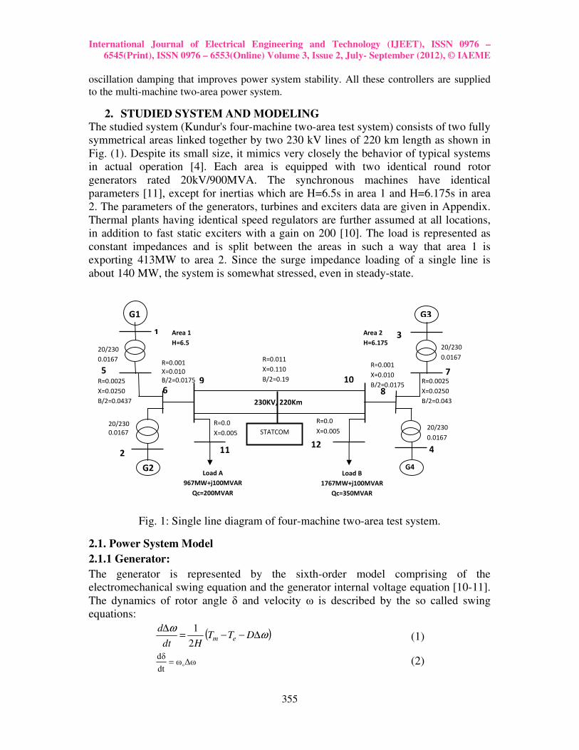
Governor and Turbine Model:
A typical overview of primary control in a steam unit is presented in Fig. (4),
functional blocks include the governor speed changer, speed governor, speed
controlled valves, and turbine systems. All the equipments with some simplification
can be mathematically represented by simple block-based models. In the models, only
one control valve CV between the steam generator and HP turbine is assumed [1
Also, the models are built without intercept valves, fast valving. Boiler pressure is
Fig. 4: Steam unit primary control blocks.
The block diagram of Fig. (5) shows an approximate model for a typical mechanical
governing system. In the figure, TSR and TSM are the speed governor
and servomotor time constants, respectively. Also, Cv-open, Cv-close, Copen
represent the valve’s rate limits and position limits, respectively. Although it is
to extract the parameters of the governor model using dimensions and
], we just confine the study to the turbine model. Thus, for the
governor model, only speed governor gain is taken into account using K
ntage of steady-state speed regulation or unit droop. Other
parameters are considered to be typical values [14].
Fig. 5: Simple mechanical-hydraulic speed-governing model.
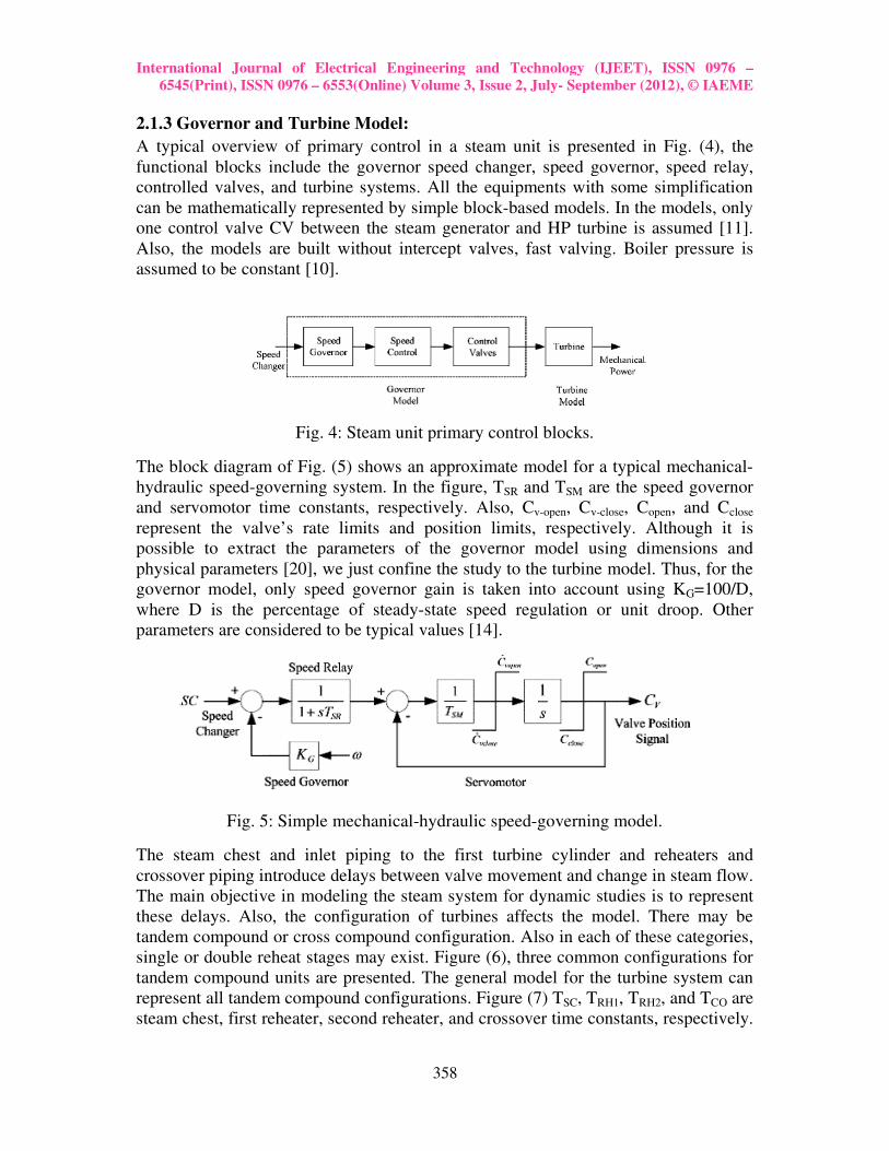
The steam chest and inlet piping to the first turbine cylinder and reheaters
crossover piping introduce delays between valve movement and change in steam flow.
The main objective in modeling the steam system for dynamic studies is to represent
these delays. Also, the configuration of turbines affects the model. There may be
dem compound or cross compound configuration. Also in each of these categories,
single or double reheat stages may exist. Figure (6), three common configurations for
tandem compound units are presented. The general model for the turbine system can
t all tandem compound configurations. Figure (7) TSC, TRH1, TRH2, and T
steam chest, first reheater, second reheater, and crossover time constants, respectively.
International Journal of Electrical Engineering and Technology (IJEET), ISSN 0976 –
September (2012), © IAEME
m unit is presented in Fig. (4), the
functional blocks include the governor speed changer, speed governor, speed relay,
controlled valves, and turbine systems. All the equipments with some simplification
based models. In the models, only
one control valve CV between the steam generator and HP turbine is assumed [11].
Also, the models are built without intercept valves, fast valving. Boiler pressure is
The block diagram of Fig. (5) shows an approximate model for a typical mechanical-
are the speed governor
open, and Cclose
represent the valve’s rate limits and position limits, respectively. Although it is
to extract the parameters of the governor model using dimensions and
], we just confine the study to the turbine model. Thus, for the
governor model, only speed governor gain is taken into account using KG=100/D,
state speed regulation or unit droop. Other
The steam chest and inlet piping to the first turbine cylinder and reheaters and
crossover piping introduce delays between valve movement and change in steam flow.
The main objective in modeling the steam system for dynamic studies is to represent
these delays. Also, the configuration of turbines affects the model. There may be
dem compound or cross compound configuration. Also in each of these categories,
single or double reheat stages may exist. Figure (6), three common configurations for
tandem compound units are presented. The general model for the turbine system can
, and TCO are
steam chest, first reheater, second reheater, and crossover time constants, respectively.
International Journal of Electrical Engineering and Technology (IJEET), ISSN 0976
6545(Print), ISSN 0976 – 6553(Online) Volume 3, Issue 2, July
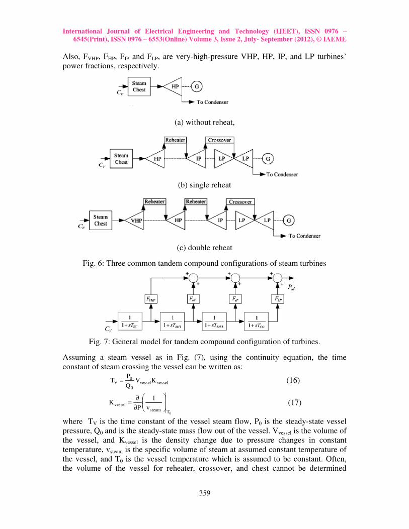
Also, FVHP, FHP, FIP and FLP, are very
power fractions, respectively.
Fig. 6: Three common tandem compound configurations of steam turbines
Fig. 7: General model for tandem compound configuration of turbines.
Assuming a steam vessel as in Fig. (7), using the continuity equation, the time
constant of steam crossing the vessel can be written as:
vesselvessel
0
0V KV
Q
PT =
steamvessel
v
1
PK
∂
∂=
where TV is the time constant of the vessel steam flow, P
pressure, Q0 and is the steady-
the vessel, and Kvessel is the density change due to pressure changes in constant
temperature, vsteam is the specific volume of steam at assumed constant temperature of
the vessel, and T0 is the vessel temperature which is assumed to be constant. Often,
the volume of the vessel for reheater, crossover, and chest cannot be determined
International Journal of Electrical Engineering and Technology (IJEET), ISSN 0976
6553(Online) Volume 3, Issue 2, July- September (2012), © IAEME
359
, are very-high-pressure VHP, HP, IP, and LP turbines’
fractions, respectively.
(a) without reheat,
(b) single reheat
(c) double reheat
Fig. 6: Three common tandem compound configurations of steam turbines
Fig. 7: General model for tandem compound configuration of turbines.
vessel as in Fig. (7), using the continuity equation, the time
constant of steam crossing the vessel can be written as:
vessel (16)
0T
(17)
is the time constant of the vessel steam flow, P0 is the steady
-state mass flow out of the vessel. Vvessel is the volume of
is the density change due to pressure changes in constant
is the specific volume of steam at assumed constant temperature of
is the vessel temperature which is assumed to be constant. Often,
the volume of the vessel for reheater, crossover, and chest cannot be determined
International Journal of Electrical Engineering and Technology (IJEET), ISSN 0976 –
September (2012), © IAEME
pressure VHP, HP, IP, and LP turbines’
Fig. 6: Three common tandem compound configurations of steam turbines
Fig. 7: General model for tandem compound configuration of turbines.
vessel as in Fig. (7), using the continuity equation, the time
is the steady-state vessel
is the volume of
is the density change due to pressure changes in constant
is the specific volume of steam at assumed constant temperature of
is the vessel temperature which is assumed to be constant. Often,
the volume of the vessel for reheater, crossover, and chest cannot be determined
International Journal of Electrical Engineering and Technology (IJEET), ISSN 0976 –
6545(Print), ISSN 0976 – 6553(Online) Volume 3, Issue 2, July- September (2012), © IAEME
360
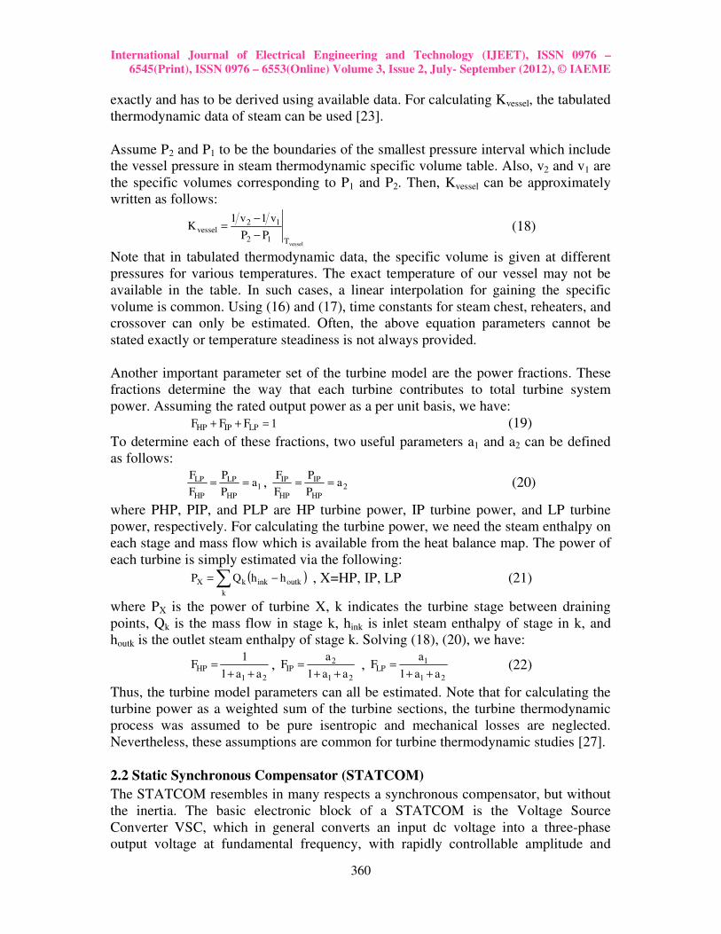
exactly and has to be derived using available data. For calculating Kvessel, the tabulated
thermodynamic data of steam can be used [23].
Assume P2 and P1 to be the boundaries of the smallest pressure interval which include
the vessel pressure in steam thermodynamic specific volume table. Also, v2 and v1 are
the specific volumes corresponding to P1 and P2. Then, Kvessel can be approximately
written as follows:
vesselT12
12vessel
PP
v1v1K
−
−= (18)
Note that in tabulated thermodynamic data, the specific volume is given at different
pressures for various temperatures. The exact temperature of our vessel may not be
available in the table. In such cases, a linear interpolation for gaining the specific
volume is common. Using (16) and (17), time constants for steam chest, reheaters, and
crossover can only be estimated. Often, the above equation parameters cannot be
stated exactly or temperature steadiness is not always provided.
Another important parameter set of the turbine model are the power fractions. These
fractions determine the way that each turbine contributes to total turbine system
power. Assuming the rated output power as a per unit basis, we have:
1FFF LPIPHP =++ (19)
To determine each of these fractions, two useful parameters a1 and a2 can be defined
as follows:
1HP
LP
HP
LP aP
P
F
F== , 2
HP
IP
HP
IP aP
P
F
F== (20)
where PHP, PIP, and PLP are HP turbine power, IP turbine power, and LP turbine
power, respectively. For calculating the turbine power, we need the steam enthalpy on
each stage and mass flow which is available from the heat balance map. The power of
each turbine is simply estimated via the following:
( )∑ −=k
outkinkkX hhQP , X=HP, IP, LP (21)
where PX is the power of turbine X, k indicates the turbine stage between draining
points, Qk is the mass flow in stage k, hink is inlet steam enthalpy of stage in k, and
houtk is the outlet steam enthalpy of stage k. Solving (18), (20), we have:
21HP
aa1
1F
++= ,
21
2IP
aa1
aF
++= ,
21
1LP
aa1
aF
++= (22)
Thus, the turbine model parameters can all be estimated. Note that for calculating the
turbine power as a weighted sum of the turbine sections, the turbine thermodynamic
process was assumed to be pure isentropic and mechanical losses are neglected.
Nevertheless, these assumptions are common for turbine thermodynamic studies [27].
2.2 Static Synchronous Compensator (STATCOM)
The STATCOM resembles in many respects a synchronous compensator, but without
the inertia. The basic electronic block of a STATCOM is the Voltage Source
Converter VSC, which in general converts an input dc voltage into a three-phase
output voltage at fundamental frequency, with rapidly controllable amplitude and
International Journal of Electrical Engineering and Technology (IJEET), ISSN 0976
6545(Print), ISSN 0976 – 6553(Online) Volume 3, Issue 2, July
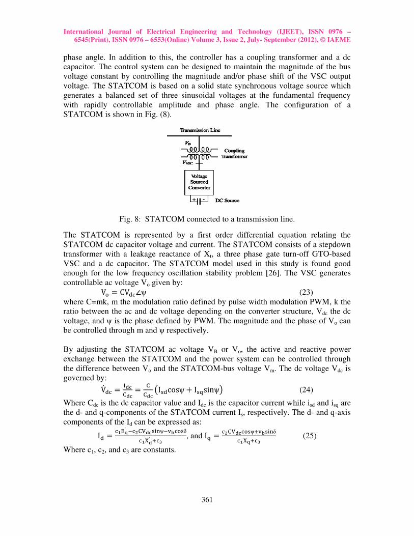
phase angle. In addition to this, the controller has a coupling transformer and a dc
capacitor. The control system can be designed to maintain the magnitude of the bus
voltage constant by controllin
voltage. The STATCOM is based on a solid state synchronous voltage source which
generates a balanced set of three sinusoidal voltages at the fundamental frequency
with rapidly controllable amplitude and
STATCOM is shown in Fig. (8).
Fig. 8: STATCOM connected to a transmission line.
The STATCOM is represented by a first order differential equation relating the
STATCOM dc capacitor voltage and current. The
transformer with a leakage reactance of X
VSC and a dc capacitor. The STATCOM model used in this study is found good
enough for the low frequency oscillation stability problem [
controllable ac voltage Vo given by:
V� � CV��∠ψ
where C=mk, m the modulation ratio defined by pulse width modulation
ratio between the ac and dc voltage depending on the converter structure, V
voltage, and ψ is the phase defined by PWM. The magnitude and the phase of V
be controlled through m and ψ respectively.
By adjusting the STATCOM ac voltage V
exchange between the STATCOM and the power system can be controlled through
the difference between Vo and the STATCOM
governed by:
V��� � �
��� �
�� I��
Where Cdc is the dc capacitor
the d- and q-components of the STATCOM current I
components of the Id can be expressed as:
I� �����
′ ���������ψ
���′ ���
Where c1, c2, and c3 are constants.
International Journal of Electrical Engineering and Technology (IJEET), ISSN 0976
6553(Online) Volume 3, Issue 2, July- September (2012), © IAEME
361
phase angle. In addition to this, the controller has a coupling transformer and a dc
capacitor. The control system can be designed to maintain the magnitude of the bus
voltage constant by controlling the magnitude and/or phase shift of the VSC output
voltage. The STATCOM is based on a solid state synchronous voltage source which
generates a balanced set of three sinusoidal voltages at the fundamental frequency
with rapidly controllable amplitude and phase angle. The configuration of a
STATCOM is shown in Fig. (8).
Fig. 8: STATCOM connected to a transmission line.
The STATCOM is represented by a first order differential equation relating the
STATCOM dc capacitor voltage and current. The STATCOM consists of a stepdown
transformer with a leakage reactance of Xt, a three phase gate turn-off GTO
VSC and a dc capacitor. The STATCOM model used in this study is found good
enough for the low frequency oscillation stability problem [26]. The VSC generates
given by:
(23)
where C=mk, m the modulation ratio defined by pulse width modulation
ratio between the ac and dc voltage depending on the converter structure, V
is the phase defined by PWM. The magnitude and the phase of V
olled through m and ψ respectively.
By adjusting the STATCOM ac voltage VB or Vo, the active and reactive power
exchange between the STATCOM and the power system can be controlled through
and the STATCOM-bus voltage Vm. The dc v
��cosψ� I��sinψ" (24)
is the dc capacitor value and Idc is the capacitor current while i
components of the STATCOM current Is, respectively. The d
can be expressed as: ψ�#$���δ
, and I� � ��������ψ�#$���δ
������� (25)
are constants.
International Journal of Electrical Engineering and Technology (IJEET), ISSN 0976 –
September (2012), © IAEME
phase angle. In addition to this, the controller has a coupling transformer and a dc
capacitor. The control system can be designed to maintain the magnitude of the bus
g the magnitude and/or phase shift of the VSC output
voltage. The STATCOM is based on a solid state synchronous voltage source which
generates a balanced set of three sinusoidal voltages at the fundamental frequency
phase angle. The configuration of a
The STATCOM is represented by a first order differential equation relating the
STATCOM consists of a stepdown
off GTO-based
VSC and a dc capacitor. The STATCOM model used in this study is found good
VSC generates
(23)
where C=mk, m the modulation ratio defined by pulse width modulation PWM, k the
ratio between the ac and dc voltage depending on the converter structure, Vdc the dc
is the phase defined by PWM. The magnitude and the phase of Vo can
, the active and reactive power
exchange between the STATCOM and the power system can be controlled through
. The dc voltage Vdc is
(24)
is the capacitor current while isd and isq are
, respectively. The d- and q-axis
(25)
International Journal of Electrical Engineering and Technology (IJEET), ISSN 0976 –
6545(Print), ISSN 0976 – 6553(Online) Volume 3, Issue 2, July- September (2012), © IAEME
362
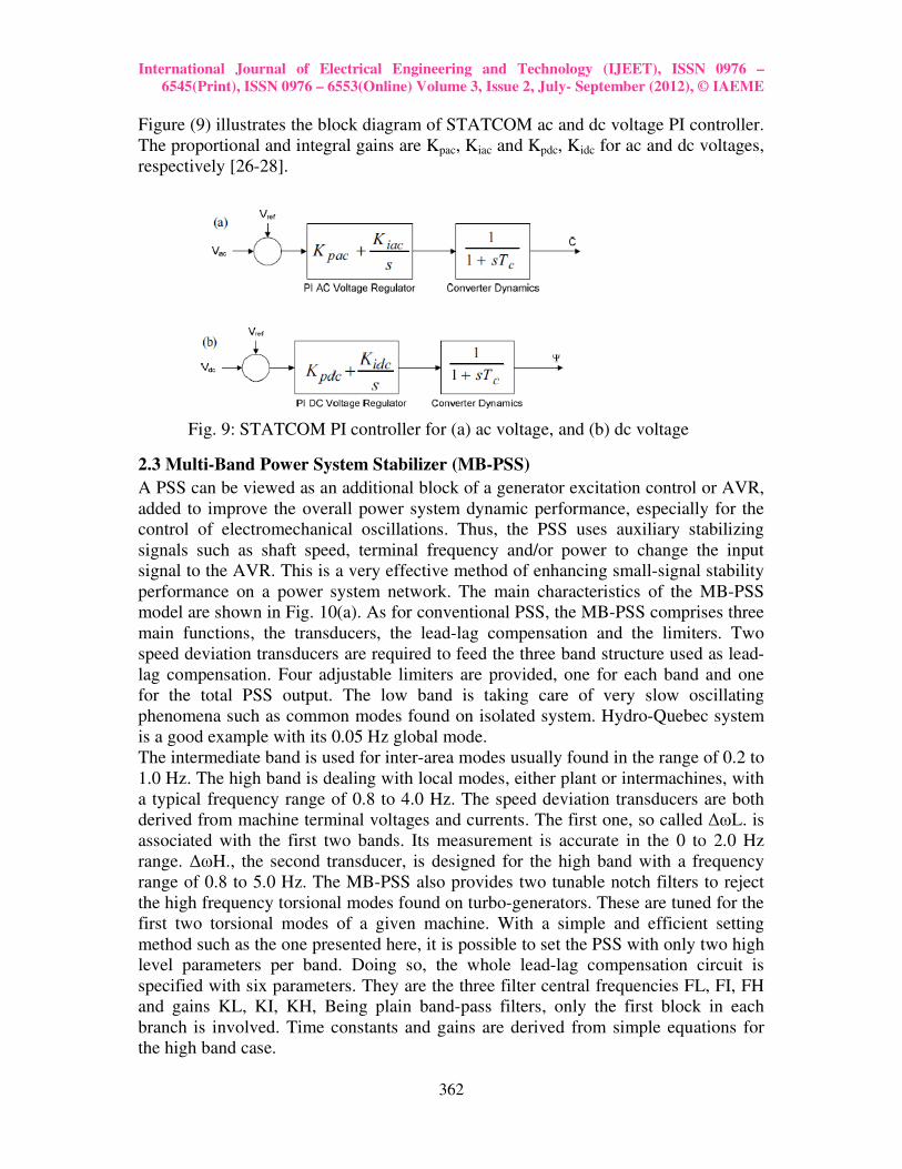
Figure (9) illustrates the block diagram of STATCOM ac and dc voltage PI controller.
The proportional and integral gains are Kpac, Kiac and Kpdc, Kidc for ac and dc voltages,
respectively [26-28].
Fig. 9: STATCOM PI controller for (a) ac voltage, and (b) dc voltage
2.3 Multi-Band Power System Stabilizer (MB-PSS)
A PSS can be viewed as an additional block of a generator excitation control or AVR,
added to improve the overall power system dynamic performance, especially for the
control of electromechanical oscillations. Thus, the PSS uses auxiliary stabilizing
signals such as shaft speed, terminal frequency and/or power to change the input
signal to the AVR. This is a very effective method of enhancing small-signal stability
performance on a power system network. The main characteristics of the MB-PSS
model are shown in Fig. 10(a). As for conventional PSS, the MB-PSS comprises three
main functions, the transducers, the lead-lag compensation and the limiters. Two
speed deviation transducers are required to feed the three band structure used as lead-
lag compensation. Four adjustable limiters are provided, one for each band and one
for the total PSS output. The low band is taking care of very slow oscillating
phenomena such as common modes found on isolated system. Hydro-Quebec system
is a good example with its 0.05 Hz global mode.
The intermediate band is used for inter-area modes usually found in the range of 0.2 to
1.0 Hz. The high band is dealing with local modes, either plant or intermachines, with
a typical frequency range of 0.8 to 4.0 Hz. The speed deviation transducers are both
derived from machine terminal voltages and currents. The first one, so called ∆ωL. is
associated with the first two bands. Its measurement is accurate in the 0 to 2.0 Hz
range. ∆ωH., the second transducer, is designed for the high band with a frequency
range of 0.8 to 5.0 Hz. The MB-PSS also provides two tunable notch filters to reject
the high frequency torsional modes found on turbo-generators. These are tuned for the
first two torsional modes of a given machine. With a simple and efficient setting
method such as the one presented here, it is possible to set the PSS with only two high
level parameters per band. Doing so, the whole lead-lag compensation circuit is
specified with six parameters. They are the three filter central frequencies FL, FI, FH
and gains KL, KI, KH, Being plain band-pass filters, only the first block in each
branch is involved. Time constants and gains are derived from simple equations for
the high band case.
International Journal of Electrical Engineering and Technology (IJEET), ISSN 0976
6545(Print), ISSN 0976 – 6553(Online) Volume 3, Issue 2, July
K&'' � K&'( �T&* � T&( �
*π+
T&' � ,-�
., and T
K&' � K&* � .
.�
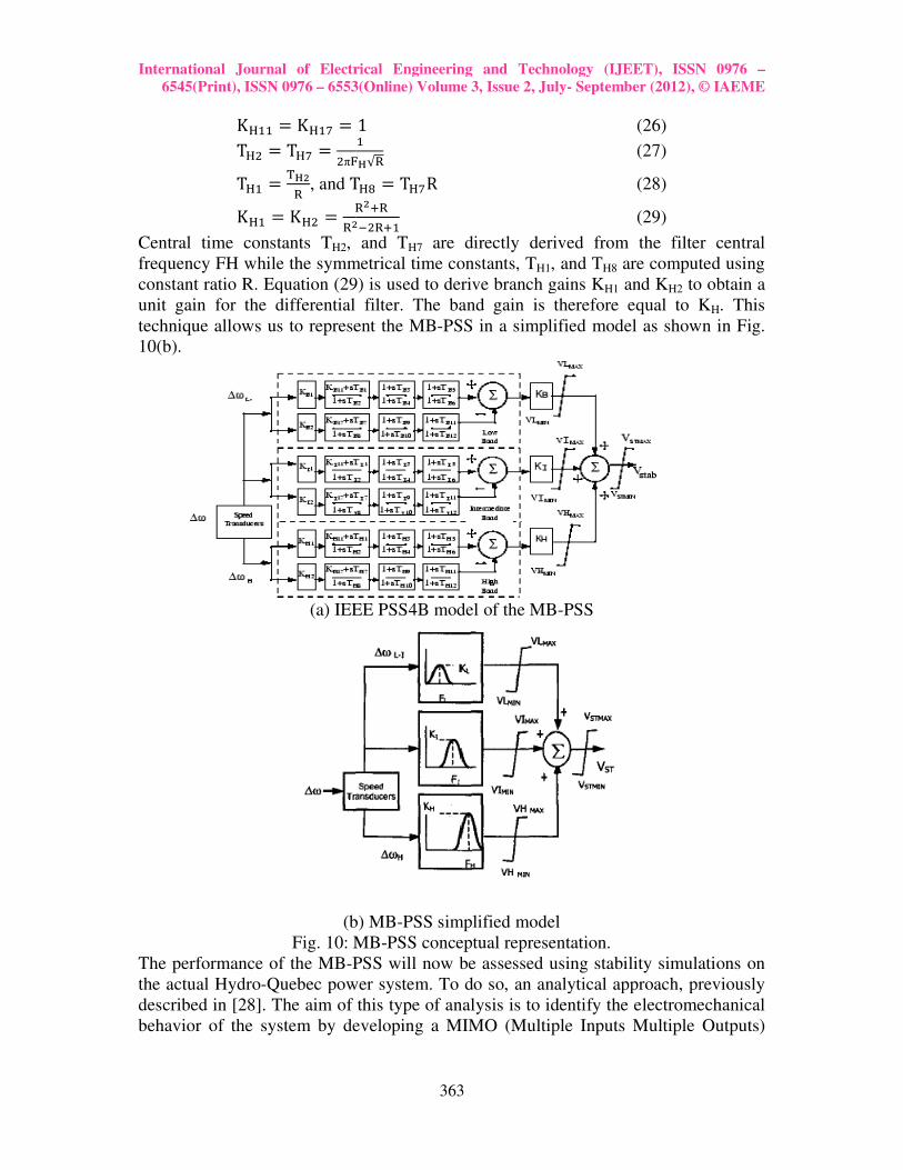
Central time constants TH2, and T
frequency FH while the symmetrical time constants, T
constant ratio R. Equation (29) is used to derive branch gains K
unit gain for the differential filter. The band gain is therefore equal to K
technique allows us to represent the MB
10(b).
(a) IEEE PSS4B model of the MB
(b)
Fig. 10: MB
The performance of the MB-PSS will now be assessed using stability simulations on
the actual Hydro-Quebec power system. To do so, an analytical approach, previously
described in [28]. The aim of this type of analysis is to identify the electromechanical
behavior of the system by developing a MIMO (Multiple Inputs Multiple Outputs)
International Journal of Electrical Engineering and Technology (IJEET), ISSN 0976
6553(Online) Volume 3, Issue 2, July- September (2012), © IAEME
363
1 (26) '
+-√. (27)
T&1 � T&(R (28)
.��.��*.�'
(29)
, and TH7 are directly derived from the filter central
frequency FH while the symmetrical time constants, TH1, and TH8 are computed using
constant ratio R. Equation (29) is used to derive branch gains KH1 and KH2
unit gain for the differential filter. The band gain is therefore equal to K
technique allows us to represent the MB-PSS in a simplified model as shown in Fig.
(a) IEEE PSS4B model of the MB-PSS
(b) MB-PSS simplified model
Fig. 10: MB-PSS conceptual representation.
PSS will now be assessed using stability simulations on
Quebec power system. To do so, an analytical approach, previously
im of this type of analysis is to identify the electromechanical
behavior of the system by developing a MIMO (Multiple Inputs Multiple Outputs)
International Journal of Electrical Engineering and Technology (IJEET), ISSN 0976 –
September (2012), © IAEME
are directly derived from the filter central
are computed using
H2 to obtain a
unit gain for the differential filter. The band gain is therefore equal to KH. This
PSS in a simplified model as shown in Fig.
PSS will now be assessed using stability simulations on
Quebec power system. To do so, an analytical approach, previously
im of this type of analysis is to identify the electromechanical
behavior of the system by developing a MIMO (Multiple Inputs Multiple Outputs)
International Journal of Electrical Engineering and Technology (IJEET), ISSN 0976 –
6545(Print), ISSN 0976 – 6553(Online) Volume 3, Issue 2, July- September (2012), © IAEME
364
type of conventional linear model (A,B,C,D) fulfilling the following state equations
[25, 30]:
x4�' � Ax4 � Bu4 (30)
y4 � Cx4 � Du4 (31)
In large power systems, participation factors corresponding to the speed deviation of
generating units can be used for initial screening of generators on which to add PSS.
However, a high participation factor is a necessary but not sufficient condition for a
PSS at the given generator to effectively damp oscillation. Following the initial
screening a more rigorous evaluation using residues and frequency response should be
carried out to determine the most suitable locations for the stabilizers.
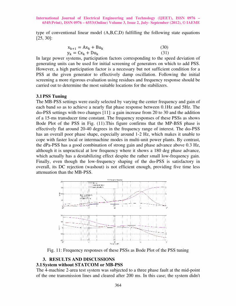
3.1 PSS Tuning
The MB-PSS settings were easily selected by varying the center frequency and gain of
each band so as to achieve a nearly flat phase response between 0.1Hz and 5Hz. The
dω-PSS settings with two changes [11]: a gain increase from 20 to 30 and the addition
of a 15-ms transducer time constant. The frequency responses of these PSSs as shows
Bode Plot of the PSS in Fig. (11).This figure confirms that the MP-BSS phase is
effectively flat around 20-40 degrees in the frequency range of interest. The dω-PSS
has an overall poor phase shape, especially around 1-2 Hz, which makes it unable to
cope with faster local or intermachine modes in multi-unit power plants. By contrast,
the dPa-PSS has a good combination of strong gain and phase advance above 0.3 Hz,
although it is unpractical at low frequency where it shows a 180 deg phase advance,
which actually has a destabilizing effect despite the rather small low-frequency gain.
Finally, even though the low-frequency shaping of the dω-PSS is satisfactory in
overall, its DC rejection (washout) is not efficient enough, providing five time less
attenuation than the MB-PSS.
Fig. 11: Frequency responses of these PSSs as Bode Plot of the PSS tuning
3. RESULTS AND DISCUSSIONS
3.1 System without STATCOM or MB-PSS The 4-machine 2-area test system was subjected to a three phase fault at the mid-point
of the one transmission lines and cleared after 200 ms. In this case; the system didn't

International Journal of Electrical Engineering and Technology (IJEET), ISSN 0976 –
6545(Print), ISSN 0976 – 6553(Online) Volume 3, Issue 2, July- September (2012), © IAEME
365
have any stabilizer such as PSS or FACTS devices. Therefore, the system stability
was affected by this three-phase fault and led the system to be unstable. The responses
of the test system are shown in Fig. (12). The performance of the rotor angle δ, speed
deviation ∆ω, the terminal voltage Vt, the field excitation voltage Efd, acceleration
power Pa and tie line power Ptie in the two area system are shown below.
(a) Rotor angle δ14, in deg. (b) Speed Deviation dω1, pu.
(c) Voltage Terminal Vt1, pu. (d) Exciter Voltage Efd1, pu.
(e) Acceleration Power Pa1, pu. (f) Power Tie Line Ptie, MW
Fig. 12: Four-machine two-area test system with 3-Φ fault and without MB-PSS or
STATCOM
3.2 System with STATCOM device and without MB-PSS
If the STATCOM controller is added to the above test system (4-machine 2-area
system) and subjected to the same 3-Φ fault, then the system response maintain to be
stable and the oscillations nearly damped. Figure (13) shows the performance of the
rotor angle δ, speed deviation dω, the terminal voltage Vt, the field excitation voltage
Rotor Angle - delta 1-4
-50
0
50
100
150
200
0 10 20 30 40 50
time, sec.
delt
a,
de
g.
Speed Deviation - dw1
1
1.002
1.004
1.006
1.008
1.01
1.012
1.014
0 10 20 30 40 50
time, sec.
dw
1,
pu
Terminal Voltage - Vt1
0.97
0.99
1.01
1.03
1.05
1.07
0 10 20 30 40 50time, sec.
Vt1
, p
u
Exciter Voltage - Efd1
0
1
2
3
4
5
6
7
0 10 20 30 40 50
time, sec.
Efd
1, p
u
Acceleration Power - Pa1
-0.22
-0.12
-0.02
0.08
0.18
0.28
0 10 20 30 40 50
time, sec.
Pa
1,
pu
Tie-line Power - Ptie
-300
-100
100
300
500
700
0 10 20 30 40 50
time, sec.
Pti
e,
pu

International Journal of Electrical Engineering and Technology (IJEET), ISSN 0976 –
6545(Print), ISSN 0976 – 6553(Online) Volume 3, Issue 2, July- September (2012), © IAEME
366
Efd, acceleration power Pa and tie line power Ptie when the disturbance of 3-Φ fault has
occurred in the two-area system with STATCOM controllers of +/-500MVA
converter rating fixed at each end of the two areas.
(a) Rotor angle δ14, in deg. (b) Speed Deviation dω1, pu.
(c) Voltage Terminal Vt1, pu. (d) Exciter Voltage Efd1, pu.
(e) Acceleration Power Pa1, pu. (f) Power Tie Line Ptie, MW
Fig. 13: Four-machine two-area test system with STATCOM controller under 3-Φ
fault
3.3 System with MB-PSS and without STATCOM
If the MB-PSS is used with the exciter of each machine in the test system (4-machine
2-area system), and the system is subjected to the same 3-Φ fault, then the system
response maintain to be stable and the oscillations are damped. Figure (14) shows the
performance of the rotor angle δ, speed deviation dω, the terminal voltage Vt, the field
Rotor Angle - delta 1-4
0
10
20
30
40
50
60
70
80
0 10 20 30 40 50time, sec.
delt
a 1
-4, deg
.
w ith STATCOM
Speed Deviation - dw1
0.996
0.998
1
1.002
1.004
1.006
0 10 20 30 40 50time, sec.
dw
1, p
u
w ith STATCOM
Terminal Voltage - Vt1
0.97
0.98
0.99
1
1.01
1.02
1.03
1.04
1.05
0 10 20 30 40 50
time, sec.
Vt1
, p
u
w ith STATCOM
Exciter Voltage Efd1
-1
0
1
2
3
4
5
6
7
8
0 10 20 30 40 50
time, sec.
Efd
1, p
uw ith STATCOM
Acceleration Power - Pa1
-0.2
-0.1
0
0.1
0.2
0.3
0 10 20 30 40 50
time, sec.
Pa
1,
pu
w ith STATCOM
Tie line Power - Ptie
0
100
200
300
400
500
600
700
0 10 20 30 40 50time, sec.
Pti
e, p
u
w ith STATCOM
International Journal of Electrical Engineering and Technology (IJEET), ISSN 0976 –
6545(Print), ISSN 0976 – 6553(Online) Volume 3, Issue 2, July- September (2012), © IAEME
367
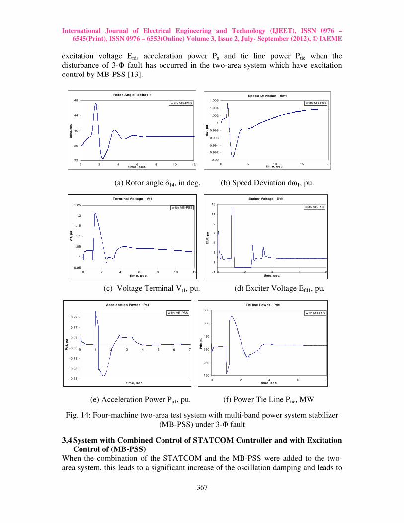
excitation voltage Efd, acceleration power Pa and tie line power Ptie when the
disturbance of 3-Φ fault has occurred in the two-area system which have excitation
control by MB-PSS [13].
(a) Rotor angle δ14, in deg. (b) Speed Deviation dω1, pu.
(c) Voltage Terminal Vt1, pu. (d) Exciter Voltage Efd1, pu.
(e) Acceleration Power Pa1, pu. (f) Power Tie Line Ptie, MW
Fig. 14: Four-machine two-area test system with multi-band power system stabilizer
(MB-PSS) under 3-Φ fault
3.4 System with Combined Control of STATCOM Controller and with Excitation
Control of (MB-PSS)
When the combination of the STATCOM and the MB-PSS were added to the two-
area system, this leads to a significant increase of the oscillation damping and leads to
Rotor Angle -delta1-4
32
36
40
44
48
0 2 4 6 8 10 12time, sec.
delta, sec.
w ith MB-PSS
Speed Deviation - dw1
0.99
0.992
0.994
0.996
0.998
1
1.002
1.004
1.006
0 5 10 15 20time, sec.
dw
1, pu
w ith MB-PSS
Terminal Voltage - Vt1
0.95
1
1.05
1.1
1.15
1.2
1.25
0 2 4 6 8 10 12
time, sec.
Vt1
, p
u
w ith MB-PSS
Exciter Voltage - Efd1
-1
1
3
5
7
9
11
13
0 2 4 6 8
time, sec.
Efd
1, p
uw ith MB-PSS
Acceleration Power - Pa1
-0.33
-0.23
-0.13
-0.03
0.07
0.17
0.27
0 1 2 3 4 5 6 7
time, sec.
Pa1, p
u
w ith MB-PSS
Tie line Power - Ptie
180
280
380
480
580
680
0 2 4 6 8time, sec.
Pti
e, p
u
w ith MB-PSS

International Journal of Electrical Engineering and Technology (IJEET), ISSN 0976 –
6545(Print), ISSN 0976 – 6553(Online) Volume 3, Issue 2, July- September (2012), © IAEME
368
Tie line Power - Ptie
180
280
380
480
580
680
0 1 2 3 4 5 6 7 8time, sec.
Ptie, pu
STATCOM
MB-PSS
the improvement of the power system stability. Comparing with the previous results,
the combination between STATCOM and MB-PSS gives more stable performance of
the system parameters. Figure (15) shows the performance of the disturbance of 3-Φ
fault occurred in the two-area system which have combined control of MB-PSS and
STATCOM.
(a) Rotor angle δ14, in deg. (b) Speed Deviation dω1, pu.
(c) Voltage Terminal Vt1, pu. (d) Exciter Voltage Efd1, pu.
(e) Acceleration Power Pa1, pu. (f) Power Tie Line Ptie, MW
Fig. 15: Four-machine two-area test system with combined STATCOM controller and
MB-PSS under 3-Φ fault
3.5 Comparison between the Three Cases (STATCOM, MB-PSS, and Combined) When the combination between the STATCOM and the MB-PSS is added to the two-
area system, this is result in a significant increase in damping oscillation which leads
Rotor Angle - delta 1-4
20
25
30
35
40
45
50
0 2 4 6 8 10 12
time, sec.
delta 1
-4, deg.
STATCOM
MB-PSS
Speed Deviation - dw 1
0.995
0.997
0.999
1.001
1.003
1.005
0 4 8 12 16 20time, sec.
dw
1, pu
STATCOM
MB-PSS
Terminal Voltage Vt1
0.92
0.97
1.02
1.07
1.12
1.17
0 2 4 6 8 10 12
time, sec.
Vt1
, pu
STATCOM
MB-PSS
Exciter voltage - Efd1
-1
1
3
5
7
9
11
13
15
0 2 4 6 8time, sec.
Efd
1, pu
STATCOM
MB-PSS
Acceleration Power - Pa1
-0.35
-0.25
-0.15
-0.05
0.05
0.15
0.25
0.35
0 2 4 6 8
time, sec.
Pa1, pu
STATCOM
MB-PSS
International Journal of Electrical Engineering and Technology (IJEET), ISSN 0976 –
6545(Print), ISSN 0976 – 6553(Online) Volume 3, Issue 2, July- September (2012), © IAEME
369
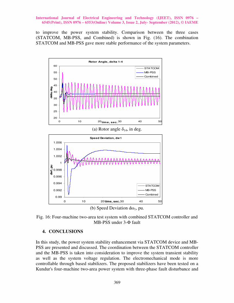
to improve the power system stability. Comparison between the three cases
(STATCOM, MB-PSS, and Combined) is shown in Fig. (16). The combination
STATCOM and MB-PSS gave more stable performance of the system parameters.
(a) Rotor angle δ14, in deg.
(b) Speed Deviation dω1, pu.
Fig. 16: Four-machine two-area test system with combined STATCOM controller and
MB-PSS under 3-Φ fault
4. CONCLUSIONS
In this study, the power system stability enhancement via STATCOM device and MB-
PSS are presented and discussed. The coordination between the STATCOM controller
and the MB-PSS is taken into consideration to improve the system transient stability
as well as the system voltage regulation. The electromechanical mode is more
controllable through based stabilizers. The proposed stabilizers have been tested on a
Kundur's four-machine two-area power system with three-phase fault disturbance and
Rotor Angle, delta 1-4
20
25
30
35
40
45
50
55
60
0 10 20 30 40 50time, sec.
delta, deg.
STATCOM
MB-PSS
Combined
Speed Deviation, dw1
0.99
0.992
0.994
0.996
0.998
1
1.002
1.004
1.006
0 10 20 30 40 50time, sec.
dw
1, pu
STATCOM
MB-PSS
Combined
International Journal of Electrical Engineering and Technology (IJEET), ISSN 0976 –
6545(Print), ISSN 0976 – 6553(Online) Volume 3, Issue 2, July- September (2012), © IAEME
370
loading conditions. The nonlinear simulation results show the effectiveness and
robustness of the proposed STATCOM controller and power system stabilizer to
enhance the system stability.
REFERENCES
[1] Sauer PW, Pai MA. Power system dynamics and stability. Englewood Cliffs, NJ, USA:
Prentice-Hall; 1998.
[2] Asgharian R. A robust H∞ power system stabilizer with no adverse effect on shaft torsional
modes. IEEE Trans Energy Conv., pp. 475–481, 1994.
[3] Kwakernaak H. Robust control and H∞ optimization—tutorial. Automatica, pp.255–273, 1993.
[4] Kundur P, Klein M, Rogers GJ, Zywno MS. Application of power system stabilizers for
enhancement of overall system stability. IEEE Trans PWRS, pp. 614–626, 1989.
[5] Gibbard MJ. Robust design of fixed-parameter power system stabilizers over a wide range of
operating conditions. IEEE Trans PWRS, pp.794–800, 1991.
[6] Heniche A., Kamwa I., and Grondin R., “Torsional-Mode Identification for Turbogenerators
with Application to PSS Tuning”, IPST’05 in Montreal, Canada on June 19-23, 2005.
[7] Mahran AR, Hogg BW, El-Sayed ML. Coordinated control of synchronous generator
excitation and static VAR compensator. IEEE Trans Energy Conv., pp. 615–622, 1992.
[8] K. R. Padiyar, and Nagesh Prabhu, Design and performance evaluation of subsynchronous
damping controller with STATCOM, IEEE Transactions on Power Delivery, Vol. 21, No. 3,
pp.1398-1405, july 2006
[9] Behrooz Vahidi, Mohammad Reza Bank Tavakoli, and Wolfgang Gawlik, Determining
parameters of turbine’s model using heat balance data of steam power unit for educational
purposes, IEEE Transactions on Power Systems, Vol. 22, No. 4, pp. 1546-1552, November
2007.
[10] “IEEE Recommended Practice for Excitation System Models for Power System Stability
Studies”, IEEE St. 421.5-2002.
[11] Mobarak Y. A., " A Simulink Multi-Band Power System Stabilizer", Journal of Engineering
Sciences, Assiut University, Vol. 35, No. 2 pp. 489-507, March 2007.
[12] Wang HF, Swift FJ. A unified model for the analysis of FACTS devices in damping power
system oscillations. Part I. Single-machine infinite-bus power systems. IEEE Trans PWRD, pp.
941–946, 1997.
[13] Abido MA, Abdel-Magid YL. Analysis and design of power system stabilizers and FACTS
based stabilizers using genetic algorithms. 14th Power Systems Computation Conference
PSCC, June 24–28, 2002.
[14] Y. A. Mobarak, “Power System Stabilization Using a Combination of Static VAR
Compensator and Multi-Band Power System Stabilizer”, International Review of Automatic
Control (I.RE.A.CO.), Praise Worthy Prize, Vol. 4, No. 1, pp. 94-101, January 2011.
[15] Rahim A, Nassimi S. Synchronous generator damping enhancement through coordinated
control of exciter and SVC. IEE Proc Gener Transm Distrib, pp. 211–218, 1996.
[16] Noroozian M, Anderson G. Damping of power system oscillations by use of controllable
components. IEEE Trans PWRD, pp. 2046–2054, 1994.
[17] M. Ahmadzadeh, S.S. Mortazavi, A. Saeedian, A novel method of coordinating PSSs and
FACTS devices in power system stability enhancement, WSEAS transactions on Power
systems, 2009.
[18] A. Ahmed, Y. A. Mobarak, O. Amer, “Power System Damping Enhancement via Coordinated
Design of PSS & TCSC”, Journal of Engineering Sciences (JES), Assiut University, Egypt,
Vol. 39, No. 1, pp. 113-122, January 2011.
[19] Du W, Wu X, Wang HF, and Dunn R, Feasibility study to damp power system multi-mode
oscillations by using a single FACTS device, Int. J Electric Power Energy System, Vol.32, pp.
645-655, 2010.
International Journal of Electrical Engineering and Technology (IJEET), ISSN 0976 –
6545(Print), ISSN 0976 – 6553(Online) Volume 3, Issue 2, July- September (2012), © IAEME
371
[20] Youssef A. Mobarak, “SVC, STATCOM, and Transmission Line Rating Enhancments on
Induction Generator Driven by Wind Turbine", International Journal of Electrical Engineering
and Technology (IJEET), Volume 3, Issue 1, pp. 326-343, Jan- June 2012.
[21] Shayeghi H, Safari A, and Shayanfar HA, PSS and TCSC damping controller coordinated
design using PSO in multi-machine power system, Energy Conversion and Management,
Vol.51, pp.2930-2937, 2010.
[22] S.F. Faisal, A.H.M.A. Rahim, J.M. Bakhashwain, A robust STATCOM controller for a
multimachine power system using particle swarm optimization and loop-shaping, International
Journal of Electrical, Computer, and Systems Engineering, pp. 64-70, 2007.
[23] Mohammad Reza Safari Tirtashi Ahmad Rohani Reza Noroozian, PSS and STATCOM
controller design for damping power system oscillations using fuzzy control strategies,
Proceedings of ICEE 2010, May 11-13, 2010
[24] S. Panda, N.P. Padhy "Optimal location and controller design of STATCOM for power system
stability improvement using PSO" Journal of the Franklin Institute, pp. 166-181, 2008.
[25] Mohammad Reza, Ahmad Rohani & Reza Noroozian, PSS and STATCOM controller design
for damping power system oscillations using fuzzy control strategies, 18th Iranian conference
on Electrical Engineering, pp. 901-906, 2010.
[26] Y. A. Mobarak, “Power Systems Voltage stability Assessment Using STATCOM ”,
International Review of Automatic Control (I.RE.A.CO.), Praise Worthy Prize, Vol. 4, No. 2,
pp. 259-266, March 2011.
[27] Mahdiyeh Eslami, Hussain Shareef, Azah Mohamed, Mohammad Khajehzadeh, Optimal
location of PSS using improved PSO with chaotic sequence, International Conference on
Electrical, Control and Computer Engineering, Pahang, Malaysia, pp. 253-258, June 21-22,
2011.
[28] J. Barati, S. S. Mortazavi, A. Saidian, Analysis and assessment of FACTS-based stabilizers for
damping power system oscillations using genetic algorithms, International Review of
Electrical Engineering, Vol. 5, No.6, pp 2819-2827, 2010.
[29] A.B. Khormizi & A.S. Nia, Damping of power system oscillations in multi-machine power
systems using coordinate design of PSS and TCSC, 10th EEEIC, pp. 1-4, 2011.
[30] Furini MA, Pereira ALS, and Araujo PB, Pole placement by coordinated tuning of power
system stabilizers and FACTS-POD stabilizers, Int. J Electric Power Energy System, Vol.33,
pp. 615-622, 2011.
[31] Youssef A. Mobarak, "Novel Controllers for Reactive Power Compensation by using
STATCOM", ICGST International Journal on Automatic Control and System Engineering
(ACSE), Vol. 12, Issue 1, pp. 9-20, June 2012.
Appendices
1- MB-PSS Simplified Settings Mode [11]:
K=1, FB=0.2Hz, KE=20, FI=0.9Hz, KI=25, FH=12Hz, KH=145, VLmax=0.075pu, VImax=0.15pu,
VHmax=0.15pu, VSmax=0.15pu
2- STATCOM parameters [26]: 230 KV, ±500 MVAR
R=0.0073pu,L=0.22pu,Vdc=40KV,Cdc=±375µF, Vref =1.0pu, Vac regulator gains Kp = 5, Ki = 1000,
Vdc regulator gains Kp = 0.1e-3, Ki = 20e-3
3- Synchronous Generator [4, 14]:
Xd=1.8pu,Xd'=0.3pu,Xd
''=0.25pu,Xq=1.7pu,Xq
'=0.55pu,Xq
''=0.25pu,Xl=0.2pu,Rs=0.0025pu,Tdo
'=8sec,T
do''=0.03sec,Tqo
'=0.4sec, Tqo''=0.05sec,H=6.5sec, p=4
4- Excitation System [4, 10]:
Tr=0.02sec, Ka=300, Ta=0.001, Ke=1, Te=0, Tb=0, Tc=0, Kf=0.001, Tf=0.1sec, Efmin= -11.5, Efmax=11.5
5- Steam Turbine and Governor [10, 11]:
Kp=1, Rp=0.05, Dz=0, Tsr=0.001, Tsm=0.15, and Vgmin=-0.1, Vgmax=0.1pu/s, gmin=0, gmax=4.496, and
T2=0, T3=10, T4=3.3, T5=0.5, and F2=0.5, F3=0.5, F4=0, F5=0, and H3=0.24897, H4=0, H5=0, and
K12=83.47, K23=42.702, K34=0, K45=0pu/rad, and D2=2.4832, D3=0.4, D4=0, D5=0pu, torque/pu speed
deviation.

International Journal of Electrical Engineering and Technology (IJEET), ISSN 0976 –
6545(Print), ISSN 0976 – 6553(Online) Volume 3, Issue 2, July- September (2012), © IAEME
372
Biographies
Gaber Shabib: He received his B.Sc. degree in electrical engineering from Al-
Azhar University with excellent with honor degree. In October 1982 he joins the
electrical engineering, King Fahad University of Petroleum and Minerals,
Dhahran Saudi Arabia as a research assistant. In December 1985 he received his
M.Sc. degree in electrical engineering from King Fahad University of Petroleum
and Minerals. In November 1987 he joins the Qassim Royal Institute, Qassim,
Saudi Arabia as a lecturer. He received his Ph.D. degree from Menoufia University, Egypt, in 2001.
He joined Aswan High Institute of Energy, South Valley University, Aswan, Egypt in 1999. He joined
Digital Control Laboratory, Tsukuba University, Japan as a visiting Professor 2006–2007. His
research interests are power system stability, control, Self tuning control, Fuzzy logic techniques,
Digital control techniques all as applied to power systems.
Youssef A. Mobarak was born in Egypt. He received his B.Sc. and M.Sc.
degrees in Electrical Engineering from South Valley University, Aswan, Egypt,
in 1997 and 2001 respectively and Ph.D. from Cairo University, Egypt, in 2005.
He joined Electrical Engineering Department, High Institute of Energy, South
Valley University as a Demonstrator, as an Assistant Lecturer, and as an
Assistant Professor during the periods of 1998–2001, 2001–2005, and 2005–2009
respectively. He joined Artificial Complex Systems, Hiroshima University, Japan
as a Researcher 2007–2008. Also, he joined King Abdulaziz University, Rabigh, Faculty of
Engineering 2010 to present. His research interests are power system planning, operation, and
optimization techniques applied to power systems, Nanotechnology materials via addition nano-scale
particles and additives for usage in industrial field.