3300 xl 11mm proximity transducer system · 3300 xl 11mm proximity transducer system . ... either a...
TRANSCRIPT

Specifications and Ordering Information Part Number 146256-01
Rev. F (08/14)
Page 1 of 22
3300 XL 11mm Proximity Transducer System Bently Nevada* Asset Condition Monitoring
Description Transducer System
The 3300 XL 11 mm Proximity Transducer System consists of:
• 3300 XL 11 mm probe
• 3300 XL 11 mm extension cable
• 3300 XL 11 mm Proximitor* Sensor1
The 3300 XL 11 mm Proximity Transducer System has a 3.94 V/mm (100 mV/mil) output for non-contacting vibration and displacement measurements on fluid film bearing machines. The large 11 mm tip enables this transducer system to have a longer linear range compared to our standard 3300 XL 8 mm Transducer System. It is primarily used in the following applications where the longer linear range is necessary:
• Axial (thrust) position measurements
• Ramp differential expansion measurements on steam turbines
• Rod position or rod drop measurements on reciprocating compressors
• Tachometer and zero speed measurements
• Phase reference (Keyphasor*) signals
The 3300 XL 11 mm Proximitor Sensor is designed to replace the 7200-series 11 mm and 14 mm Transducer Systems. When upgrading from the 7200-series system to the 3300 XL 11 mm system, every component must be replaced with 3300 XL 11 mm components. In addition, the monitoring system must be updated. If using a 3500 Monitoring System, an updated version of the configuration software that lists the 3300 XL 11 mm Transducer System as a compatible option is required. Existing 3300 Monitoring Systems may need a modification. Contact your local sales and service representative for assistance.
Application Advisory: The 3300 XL 11 mm Proximity Transducer is designed for measuring position or vibration within a frequency range of 0 to 8 kHz. Typical applications of this system include radial vibration and position, axial position and Keyphasor measurements. Although the terminals and connector on the Proximitor sensor have protection against electrostatic discharge, take reasonable precautions to avoid electrostatic discharge during handling.
Specifications and Ordering Information Part Number 146256-01
Rev. F (08/14)
Page 2 of 22
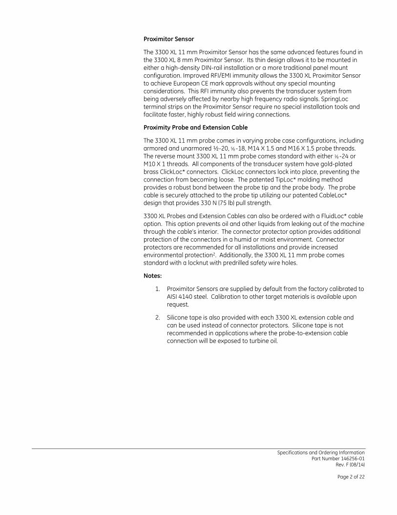
Proximitor Sensor
The 3300 XL 11 mm Proximitor Sensor has the same advanced features found in the 3300 XL 8 mm Proximitor Sensor. Its thin design allows it to be mounted in either a high-density DIN-rail installation or a more traditional panel mount configuration. Improved RFI/EMI immunity allows the 3300 XL Proximitor Sensor to achieve European CE mark approvals without any special mounting considerations. This RFI immunity also prevents the transducer system from being adversely affected by nearby high frequency radio signals. SpringLoc terminal strips on the Proximitor Sensor require no special installation tools and facilitate faster, highly robust field wiring connections.
Proximity Probe and Extension Cable
The 3300 XL 11 mm probe comes in varying probe case configurations, including armored and unarmored ½-20, 5⁄8 -18, M14 X 1.5 and M16 X 1.5 probe threads. The reverse mount 3300 XL 11 mm probe comes standard with either 3⁄8 -24 or M10 X 1 threads. All components of the transducer system have gold-plated brass ClickLoc* connectors. ClickLoc connectors lock into place, preventing the connection from becoming loose. The patented TipLoc* molding method provides a robust bond between the probe tip and the probe body. The probe cable is securely attached to the probe tip utilizing our patented CableLoc* design that provides 330 N (75 lb) pull strength.
3300 XL Probes and Extension Cables can also be ordered with a FluidLoc* cable option. This option prevents oil and other liquids from leaking out of the machine through the cable’s interior. The connector protector option provides additional protection of the connectors in a humid or moist environment. Connector protectors are recommended for all installations and provide increased environmental protection2. Additionally, the 3300 XL 11 mm probe comes standard with a locknut with predrilled safety wire holes.
Notes:
1. Proximitor Sensors are supplied by default from the factory calibrated to AISI 4140 steel. Calibration to other target materials is available upon request.
2. Silicone tape is also provided with each 3300 XL extension cable and can be used instead of connector protectors. Silicone tape is not recommended in applications where the probe-to-extension cable connection will be exposed to turbine oil.
Specifications and Ordering Information Part Number 146256-01
Rev. F (08/14)
Page 3 of 22
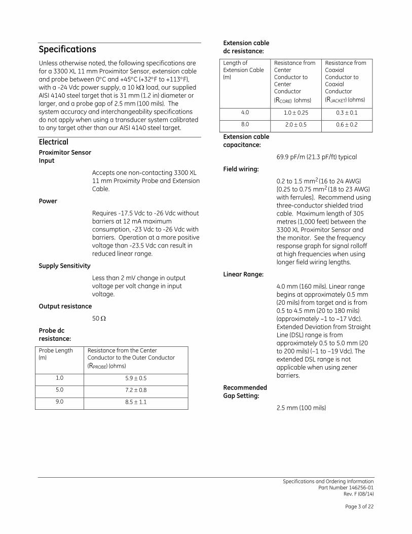
Specifications Unless otherwise noted, the following specifications are for a 3300 XL 11 mm Proximitor Sensor, extension cable and probe between 0°C and +45°C (+32°F to +113°F), with a -24 Vdc power supply, a 10 kΩ load, our supplied AISI 4140 steel target that is 31 mm (1.2 in) diameter or larger, and a probe gap of 2.5 mm (100 mils). The system accuracy and interchangeability specifications do not apply when using a transducer system calibrated to any target other than our AISI 4140 steel target.
Electrical Proximitor Sensor Input
Accepts one non-contacting 3300 XL 11 mm Proximity Probe and Extension Cable.
Power
Requires -17.5 Vdc to -26 Vdc without barriers at 12 mA maximum consumption, -23 Vdc to -26 Vdc with barriers. Operation at a more positive voltage than -23.5 Vdc can result in reduced linear range.
Supply Sensitivity
Less than 2 mV change in output voltage per volt change in input voltage.
Output resistance
50 Ω
Probe dc resistance:
Probe Length (m)
Resistance from the Center Conductor to the Outer Conductor (RPROBE) (ohms)
1.0 5.9 ± 0.5
5.0 7.2 ± 0.8
9.0 8.5 ± 1.1
Extension cable dc resistance:
Length of Extension Cable (m)
Resistance from Center Conductor to Center Conductor (RCORE) (ohms)
Resistance from Coaxial Conductor to Coaxial Conductor (RJACKET) (ohms)
4.0 1.0 ± 0.25 0.3 ± 0.1
8.0 2.0 ± 0.5 0.6 ± 0.2
Extension cable capacitance:
69.9 pF/m (21.3 pF/ft) typical
Field wiring:
0.2 to 1.5 mm2 (16 to 24 AWG) [0.25 to 0.75 mm2 (18 to 23 AWG) with ferrules]. Recommend using three-conductor shielded triad cable. Maximum length of 305 metres (1,000 feet) between the 3300 XL Proximitor Sensor and the monitor. See the frequency response graph for signal rolloff at high frequencies when using longer field wiring lengths.
Linear Range:
4.0 mm (160 mils). Linear range begins at approximately 0.5 mm (20 mils) from target and is from 0.5 to 4.5 mm (20 to 180 mils) (approximately –1 to –17 Vdc). Extended Deviation from Straight Line (DSL) range is from approximately 0.5 to 5.0 mm (20 to 200 mils) (–1 to –19 Vdc). The extended DSL range is not applicable when using zener barriers.
Recommended Gap Setting:
2.5 mm (100 mils)

Specifications and Ordering Information Part Number 146256-01
Rev. F (08/14)
Page 4 of 22
Incremental Scale Factor (ISF)
3.94 V/mm (100 mV/mil) ±10% including interchangeability error when measured in increments of 0.5 mm (20 mils) over the 4.0 mm (160 mil) linear range.
Deviation from best fit straight line (DSL)
Standard DSL range:
Less than ±0.10 mm (±4 mils).
Extended DSL range:
Less than ±0.15 mm (±6 mils).
System Performance over extended temperatures:
Over a probe temperature range of -35°C to +120°C (-31°F to +248°F) with the Proximitor Sensor and extension cable between 0°C to +45°C (+32°F to +113°F), the ISF remains within ±25% of 3.94 V/mm (100 mV/mil), the DSL remains within ±0.51 mm (±20 mils) and the extended range DSL remains within ±0.59 mm (±23 mils)
Over a Proximitor*Sensor and extension cable temperature range of -35°C to +65°C (-31°F to +149°F) with the probe between 0°C to +45°C (+32°F to +113°F), the ISF remains within ±25% of 3.94 V/mm (100 mV/mil), the DSL remains within ±0.51 mm (±20 mils) and the extended range DSL remains within ±0.59 mm (±23 mils)
Frequency Response:
0 to 8 kHz: +0, -3 dB typical, with up to 305 metres (1000 feet) of field wiring.
Recommended Minimum Target Size:
30.5 mm (1.2 in) diameter (flat target)
Recommended Minimum Shaft Diameter
152 mm (6.0 in)
Measurements on shaft diameters smaller than 76 mm (3.0 in) usually require close spacing of radial vibration or axial position transducers with the potential for their electromagnetic emitted fields to interact with one another (cross talk), resulting in erroneous readings. Care should be taken to maintain minimum separation of transducer tips, generally at least 64 mm (2.5 in) for dual axial position measurements or 54 mm (2.1 in) for radial vibration measurements to prevent cross talk. Radial vibration or position measurements on shaft diameters smaller than 152 mm (6.0 in) will generally result in a change in scale factor due to the curvature of the shaft surface. Consult Performance Specification 144979 for additional information.
Effects of 60 Hz Magnetic Fields Up to 300 Gauss (5 metre system):
Output voltage in mil pp/gauss:
Gap Proximitor Sensor
Probe Ext. Cable
0.5 mm (20 mil) 0.006 0.001 0.001
2.5 mm (100 mil)
0.033 0.009 0.005
4.6 mm (180 mil)
0.033 0.027 0.007
Electrical Classification:
Complies with the European CE mark.

Specifications and Ordering Information Part Number 146256-01
Rev. F (08/14)
Page 5 of 22
Hazardous Area Approvals Multiple approvals for hazardous areas certified by Canadian Standards Association (CSA/NRTL/C) in North America and by BASEEFA/CENELEC in Europe.
North America:
Class I, Zone 0; Ex ia IIC T1...T5 Ga for Class I, Groups A, B, C and D; Class II, Groups E, F and G; Class III when installed with intrinsically safe Certified barriers, or galvanic isolators, per drawing 141092.
Class I, Zone 2; Ex nA IIC T1...T5 Gc for Class I, Div. 2, Groups A, B, C and D when installed without barriers or galvanic isolators per drawing 140979.
T1 -51°C ≤ Ta ≤ +232°C T2 -51°C ≤ Ta ≤ +177°C T3-51°C ≤ Ta ≤ +120°C T4-51°C ≤ Ta ≤ +80°C T5-51°C ≤ Ta ≤ +40°C
Europe:
II 1 G Ex ia IIC T4/T5 Ga, Group IIC, Baseefa certificate number BAS99ATEX1101 when installed with intrinsically safe zener barriers or galvanic isolators.
II 3 G Ex nA IIC T4/T5 Gc, Group IIC, Baseefa certificate number Baseefa07ATEX0189X.
T4 @ Ta = -51°C to +100°C
T5 @ Ta = -35°C to +85°C
Mechanical Probe Tip Material:
Polyphenylene sulfide (PPS).
Probe Case Material:
AISI 304 stainless steel (SST).
Probe Cable Specifications:
75 Ω triaxial, fluoroethylene propylene (FEP) insulated probe cable in the following total probe lengths: 1, 5 or 9 metres.
Extension Cable Material:
75 Ω triaxial, fluoroethylene propylene (FEP) insulated.
Proximitor* Sensor Material:
A380 aluminum
System Length:
5 or 9 metres including extension cable
Extension Cable Armor (optional):
Flexible AISI 302 SST with FEP outer jacket.
Tensile Strength (maximum rated):
330 N (75 pounds) probe case to probe lead. 270 N (60 pounds) at probe lead to extension cable connectors.
Connector material:
Gold-plated brass
Probe case torque: Maximum Rated
Recommended
½-20 and 5⁄8 -18 probe cases
45.2 N•m
(400 in•lb)
15.0 N•m
(133 in•lb)
M14x1.5 and M16x1.5 probe cases
63.3 N•m
(560 in•lb)
21.1 N•m
(187 in•lb)
Reverse mount probes
22.6 N•m
(200 in•lb)
7.5 N•m
(66 in•lb)
Connector-to-connector torque
Recommended torque:
Finger tight
Maximum torque:
0.565 N•m (5 in•lb)

Specifications and Ordering Information Part Number 146256-01
Rev. F (08/14)
Page 6 of 22
Minimum Bend Radius (with or without sst armor):
25.4 mm (1.0 in)
System Weight (typical):
Probe:
70 g (2.5 oz) (minimum length case, 1m lead, no armor)
170 g (6.0 oz) (minimum length case, 1m lead, with armor)
For longer case lengths add 1.1 g/mm (1.0 oz/in).
For 5 m probe length add 180 g (6 oz) for non-armored probe or 560 g (20 oz) for armored probe.
For 9 m probe length add 360 g (12 oz) for non-armored probe or 1120 g (40 oz) for armored probe.
Extension Cable:
45 g/m (0.5 oz/ft)
Armored Extension cable:
140 g/m (1.5 oz/ft)
Proximitor Sensor:
255 g (9 oz)
Environmental Limits Probe Temperature Range
Operating and Storage Temperature:
-51°C to +177°C (-60°F to +351°F)
Note: Exposing the probe to temperatures below -34°C (-30°F) may cause premature failure of the pressure seal.
Extension Cable Temperature Range
Operating and Storage Temperature:
-51°C to +177°C (-60°F to +351°F)
Proximitor Sensor Temperature Range
Operating Temperature:
-51°C to +100°C (-60°F to +212°F)
Storage Temperature:
-51°C to +105°C (-60°F to +221°F)
Relative Humidity:
100% condensing, non-submersible when connectors are protected. Tested to IEC 68-2-3 damp heat.
Probe Pressure:
3300 XL probes are designed to seal differential pressure between the probe tip and case. The probe sealing material consists of a Viton* O-ring. Probes are not pressure tested prior to shipment. Contact our custom design department if you require a test of the pressure seal for your application
Note: It is the responsibility of the customer or user to ensure that all liquids and gases are contained and safely controlled should leakage occur from a proximity probe. In addition, solutions with high or low pH values may erode the tip assembly of the probe causing media leakage into surrounding areas. Bently Nevada LLC will not be held responsible for any damages resulting from leaking 3300 XL proximity probes. In addition, 3300 XL proximity probes will not be replaced under the service plan due to probe leakage.
Patents:
5,016,343
5,126,664
5,351,388
5,685,884
Components or procedures described in these patents apply to this product.
Specifications and Ordering Information Part Number 146256-01
Rev. F (08/14)
Page 7 of 22
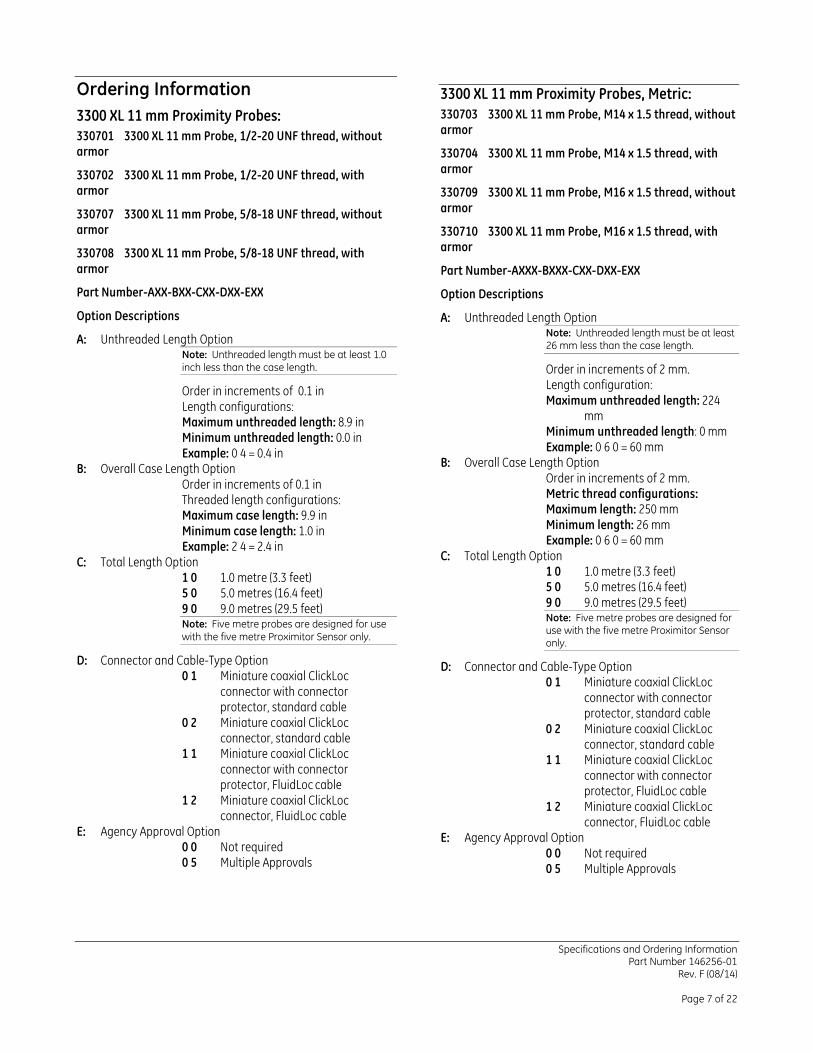
Ordering Information 3300 XL 11 mm Proximity Probes: 330701 3300 XL 11 mm Probe, 1/2-20 UNF thread, without armor
330702 3300 XL 11 mm Probe, 1/2-20 UNF thread, with armor
330707 3300 XL 11 mm Probe, 5/8-18 UNF thread, without armor
330708 3300 XL 11 mm Probe, 5/8-18 UNF thread, with armor
Part Number-AXX-BXX-CXX-DXX-EXX
Option Descriptions
A: Unthreaded Length Option Note: Unthreaded length must be at least 1.0 inch less than the case length.
Order in increments of 0.1 in Length configurations: Maximum unthreaded length: 8.9 in Minimum unthreaded length: 0.0 in Example: 0 4 = 0.4 in
B: Overall Case Length Option Order in increments of 0.1 in Threaded length configurations: Maximum case length: 9.9 in Minimum case length: 1.0 in Example: 2 4 = 2.4 in
C: Total Length Option 1 0 1.0 metre (3.3 feet) 5 0 5.0 metres (16.4 feet) 9 0 9.0 metres (29.5 feet) Note: Five metre probes are designed for use with the five metre Proximitor Sensor only.
D: Connector and Cable-Type Option 0 1 Miniature coaxial ClickLoc
connector with connector protector, standard cable
0 2 Miniature coaxial ClickLoc connector, standard cable
1 1 Miniature coaxial ClickLoc connector with connector protector, FluidLoc cable
1 2 Miniature coaxial ClickLoc connector, FluidLoc cable
E: Agency Approval Option 0 0 Not required 0 5 Multiple Approvals
3300 XL 11 mm Proximity Probes, Metric: 330703 3300 XL 11 mm Probe, M14 x 1.5 thread, without armor
330704 3300 XL 11 mm Probe, M14 x 1.5 thread, with armor
330709 3300 XL 11 mm Probe, M16 x 1.5 thread, without armor
330710 3300 XL 11 mm Probe, M16 x 1.5 thread, with armor
Part Number-AXXX-BXXX-CXX-DXX-EXX
Option Descriptions
A: Unthreaded Length Option Note: Unthreaded length must be at least 26 mm less than the case length.
Order in increments of 2 mm. Length configuration: Maximum unthreaded length: 224
mm Minimum unthreaded length: 0 mm Example: 0 6 0 = 60 mm
B: Overall Case Length Option Order in increments of 2 mm. Metric thread configurations: Maximum length: 250 mm Minimum length: 26 mm Example: 0 6 0 = 60 mm
C: Total Length Option 1 0 1.0 metre (3.3 feet) 5 0 5.0 metres (16.4 feet) 9 0 9.0 metres (29.5 feet) Note: Five metre probes are designed for use with the five metre Proximitor Sensor only.
D: Connector and Cable-Type Option 0 1 Miniature coaxial ClickLoc
connector with connector protector, standard cable
0 2 Miniature coaxial ClickLoc connector, standard cable
1 1 Miniature coaxial ClickLoc connector with connector protector, FluidLoc cable
1 2 Miniature coaxial ClickLoc connector, FluidLoc cable
E: Agency Approval Option 0 0 Not required 0 5 Multiple Approvals
Specifications and Ordering Information Part Number 146256-01
Rev. F (08/14)
Page 8 of 22
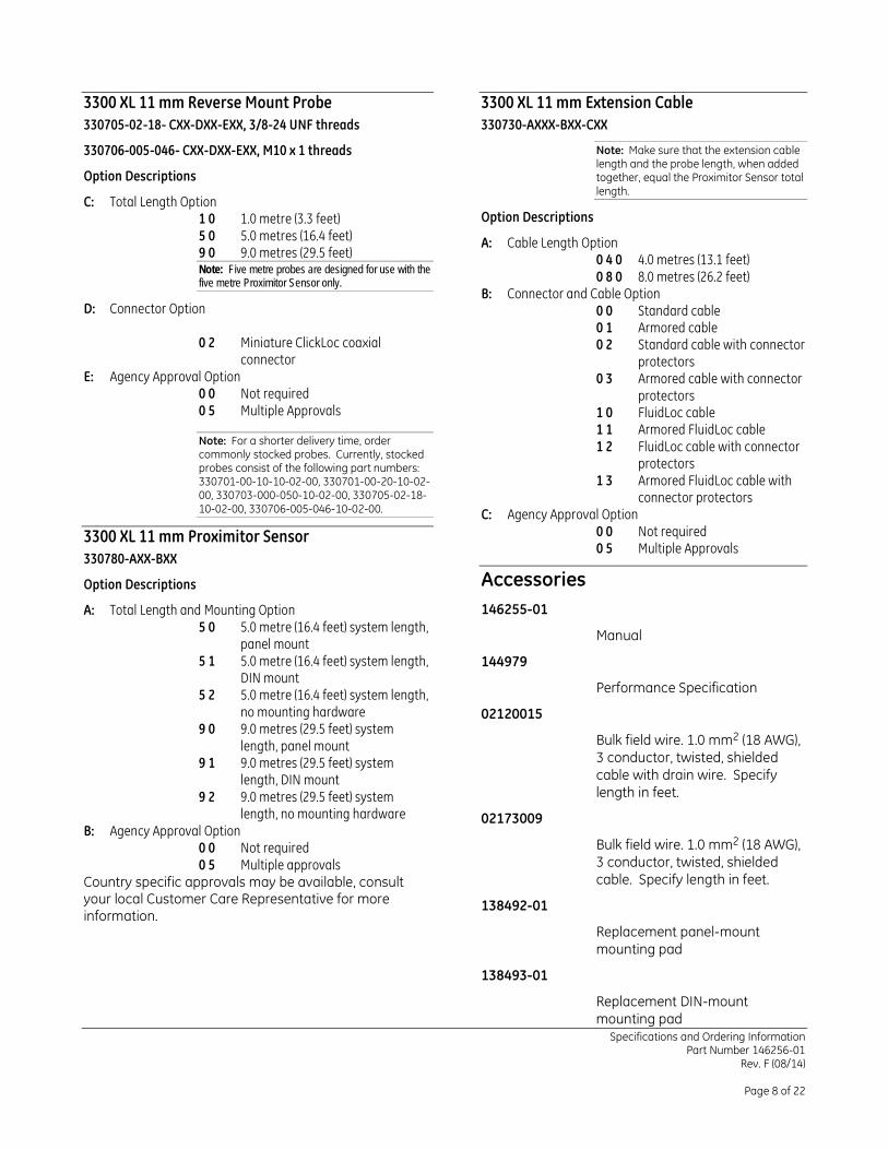
3300 XL 11 mm Reverse Mount Probe 330705-02-18- CXX-DXX-EXX, 3/8-24 UNF threads
330706-005-046- CXX-DXX-EXX, M10 x 1 threads
Option Descriptions
C: Total Length Option 1 0 1.0 metre (3.3 feet) 5 0 5.0 metres (16.4 feet) 9 0 9.0 metres (29.5 feet) Note: Five metre probes are designed for use with the five metre Proximitor Sensor only.
D: Connector Option 0 2 Miniature ClickLoc coaxial
connector E: Agency Approval Option
0 0 Not required 0 5 Multiple Approvals
Note: For a shorter delivery time, order commonly stocked probes. Currently, stocked probes consist of the following part numbers: 330701-00-10-10-02-00, 330701-00-20-10-02-00, 330703-000-050-10-02-00, 330705-02-18-10-02-00, 330706-005-046-10-02-00.
3300 XL 11 mm Proximitor Sensor 330780-AXX-BXX
Option Descriptions
A: Total Length and Mounting Option 5 0 5.0 metre (16.4 feet) system length,
panel mount 5 1 5.0 metre (16.4 feet) system length,
DIN mount 5 2 5.0 metre (16.4 feet) system length,
no mounting hardware 9 0 9.0 metres (29.5 feet) system
length, panel mount 9 1 9.0 metres (29.5 feet) system
length, DIN mount 9 2 9.0 metres (29.5 feet) system
length, no mounting hardware B: Agency Approval Option
0 0 Not required 0 5 Multiple approvals
Country specific approvals may be available, consult your local Customer Care Representative for more information.
3300 XL 11 mm Extension Cable 330730-AXXX-BXX-CXX
Note: Make sure that the extension cable length and the probe length, when added together, equal the Proximitor Sensor total length.
Option Descriptions
A: Cable Length Option 0 4 0 4.0 metres (13.1 feet) 0 8 0 8.0 metres (26.2 feet)
B: Connector and Cable Option 0 0 Standard cable 0 1 Armored cable 0 2 Standard cable with connector
protectors 0 3 Armored cable with connector
protectors 1 0 FluidLoc cable 1 1 Armored FluidLoc cable 1 2 FluidLoc cable with connector
protectors 1 3 Armored FluidLoc cable with
connector protectors C: Agency Approval Option
0 0 Not required 0 5 Multiple Approvals
Accessories 146255-01
Manual
144979
Performance Specification
02120015
Bulk field wire. 1.0 mm2 (18 AWG), 3 conductor, twisted, shielded cable with drain wire. Specify length in feet.
02173009
Bulk field wire. 1.0 mm2 (18 AWG), 3 conductor, twisted, shielded cable. Specify length in feet.
138492-01
Replacement panel-mount mounting pad
138493-01
Replacement DIN-mount mounting pad

Specifications and Ordering Information Part Number 146256-01
Rev. F (08/14)
Page 9 of 22
01609137
BNC (F) to banana plugs
01609138
Proximitor Connector Test Pin wiring (two test pins to a BNC (F) connector)
40971-04
50 Ω cable with two BNC (M) connectors. Use this cable in combination with adapter 01609137 and adapter 01609138 when checking performance of the transducer system from the Proximitor Sensor test pin holes.
04310310
3300 XL Proximitor Sensor Panel-mount Screws. Package includes four 6-32 UNC thread forming mounting screws (Supplied standard with 3300 XL Proximitor Housings [3300 XL option] ).
03200006
Silicone self-fusing tape. A 9.1 metre (10 yard) roll of silicone tape to protect connectors. It is easy to install and provides excellent electrical isolation and protection from the environment. It is not recommended for use inside the casing of the machine.
40113-02
Connector Protector Kit. Connector Protector Kit for 3300 XL probes and extension cables, including connector protectors and installation tools.
136536-01
Connector Protector Adapter. Makes our previous 3300 connector protector kits compatible with 3300 XL probes and extension cable connectors.
40180-02
Connector Protectors. Package contains 10 pairs of connector protectors.
03839410
Male Connector Protector. Placed on the extension cable to connect to the female connector protector on the probe and provide environmental protection of connectors.
03839420
Female Connector Protector. Placed on the probe lead to connect to the male connector protector on the extension cable and provide environmental protection of connectors. Also placed on the extension cable to slide over the Proximitor Sensor connection and protect it from the environment.
330153-01
3300 XL Connector Kit. Used on 3300 XL probes and extension cables. Contains one set of male and female ClickLoc* connectors, sleeves and one strip of silicone tape.
163356
Connector Crimp Tool Kit. Includes one set of 75 Ω 3300 XL ClickLoc* inserts and connector installation instructions. Supplied with carrying case.
Specifications and Ordering Information Part Number 146256-01
Rev. F (08/14)
Page 10 of 22
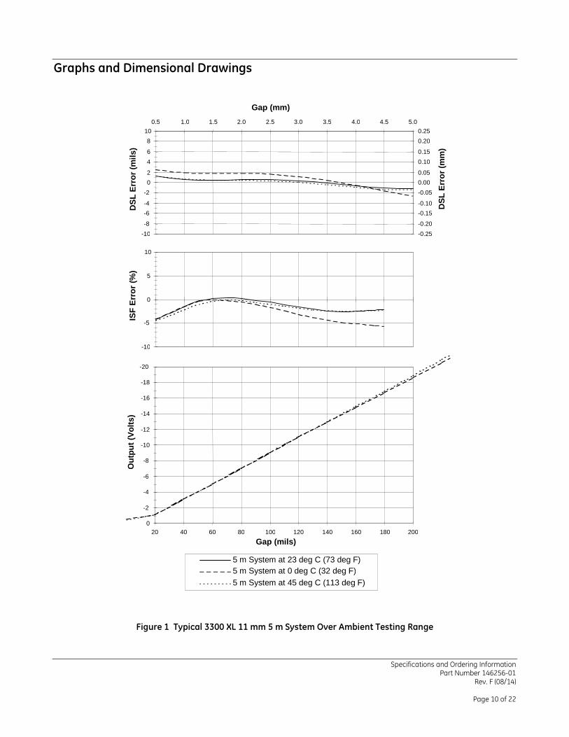
Graphs and Dimensional Drawings
Figure 1 Typical 3300 XL 11 mm 5 m System Over Ambient Testing Range
-10 -8 -6 -4 -2 0 2 4 6 8
10 D
SL E
rror
(mils
)
-0.25 -0.20 -0.15 -0.10 -0.05 0.00 0.05 0.10 0.15 0.20 0.25
0.5 1.0 1.5 2.0 2.5 3.0 3.5 4.0 4.5 5.0 Gap (mm)
DSL
Err
or (m
m)
-10
-5
0
5
10
ISF
Erro
r (%
)
-20 -18 -16 -14 -12 -10 -8 -6 -4 -2 0
20 40 60 80 100 120 140 160 180 200 Gap (mils)
Out
put (
Volts
)
5 m System at 23 deg C (73 deg F) 5 m System at 0 deg C (32 deg F) 5 m System at 45 deg C (113 deg F)

Specifications and Ordering Information Part Number 146256-01
Rev. F (08/14)
Page 11 of 22
Figure 2 Typical 3300 XL 11 mm 9 m System Over Ambient Testing Range
-10 -8 -6 -4 -2 0 2 4 6 8
10
DSL
Err
or (m
ils)
-0.25 -0.20 -0.15 -0.10 -0.05 0.00 0.05 0.10 0.15 0.20 0.25
0.5 1.0 1.5 2.0 2.5 3.0 3.5 4.0 4.5 5.0 Gap (mm)
DSL
Err
or (m
m)
-10
-5
0
5
10
ISF
Erro
r (%
)
-20 -18 -16 -14 -12 -10 -8 -6 -4 -2 0
20 40 60 80 100 120 140 160 180 200 Gap (mils)
Out
put (
Volts
)
9 m System at 23 deg C (73 deg F) 9 m System at 0 deg C (32 deg F) 9 m System at 45 deg C (113 deg F)
Specifications and Ordering Information Part Number 146256-01
Rev. F (08/14)
Page 12 of 22
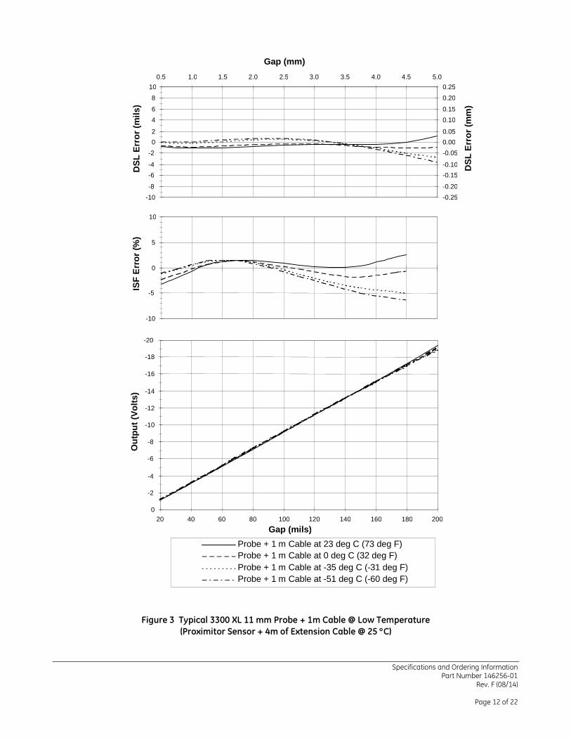
Figure 3 Typical 3300 XL 11 mm Probe + 1m Cable @ Low Temperature (Proximitor Sensor + 4m of Extension Cable @ 25 °C)
-10 -8 -6 -4 -2 0 2 4 6 8
10
DSL
Err
or (m
ils)
-0.25 -0.20 -0.15 -0.10 -0.05 0.00 0.05 0.10 0.15 0.20 0.25
0.5 1.0 1.5 2.0 2.5 3.0 3.5 4.0 4.5 5.0 Gap (mm)
DSL
Err
or (m
m)
-10
-5
0
5
10
ISF
Erro
r (%
)
-20 -18 -16 -14 -12 -10 -8 -6 -4 -2 0
20 40 60 80 100 120 140 160 180 200 Gap (mils)
Out
put (
Volts
)
Probe + 1 m Cable at 23 deg C (73 deg F) Probe + 1 m Cable at 0 deg C (32 deg F) Probe + 1 m Cable at -35 deg C (-31 deg F) Probe + 1 m Cable at -51 deg C (-60 deg F)

Specifications and Ordering Information Part Number 146256-01
Rev. F (08/14)
Page 13 of 22
Figure 4 Typical 3300 XL 11 mm Probe + 1m Cable @ High Temperature
(Proximitor Sensor + 4m of Extension Cable @ 25 °C)
-10 -8 -6 -4 -2 0 2 4 6 8
10
DSL
Err
or (m
ils)
-0.25 -0.20 -0.15 -0.10 -0.05 0.00 0.05 0.10 0.15 0.20 0.25
0.5 1.0 1.5 2.0 2.5 3.0 3.5 4.0 4.5 5.0 Gap (mm)
DSL
Err
or (m
m)
-10
-5
0
5
10
ISF
Erro
r (%
)
-20 -18 -16 -14 -12 -10 -8 -6 -4 -2 0
20 40 60 80 100 120 140 160 180 200 Gap (mils)
Out
put (
Volts
)
Probe + 1 m Cable at 23 deg C (73 deg F) Probe + 1 m Cable at 65 deg C (150 deg F) Probe + 1 m Cable at 121 deg C (250 deg F) Probe + 1 m Cable at 177 deg C (350 deg F)

Specifications and Ordering Information Part Number 146256-01
Rev. F (08/14)
Page 14 of 22
Figure 5 Typical 3300 XL 11 mm 5 m Proximitor Sensor with 4 m of Extension Cable @ Cold Temperature (Probe is at 25°C)
-10-8
-6-4
-202
46
810
DSL
Erro
r (m
ils)
-0.25-0.20
-0.15-0.10
-0.050.000.05
0.100.15
0.200.25
0.5 1.0 1.5 2.0 2.5 3.0 3.5 4.0 4.5 5.0
Gap (mm)
DSL
Erro
r (m
m)
-10
-5
0
5
10
ISF
Erro
r (%
)
-20
-18
-16
-14
-12
-10
-8
-6
-4
-2
020 40 60 80 100 120 140 160 180 200
Gap (mils)
Out
put (
Volts
)
5 m Proximitor + 4 m Cable at 23 deg C (73 deg F)
5 m Proximitor + 4 m Cable at 0 deg C (32 deg F)
5 m Proximitor + 4 m Cable at -35 deg C (-31 deg F)

Specifications and Ordering Information Part Number 146256-01
Rev. F (08/14)
Page 15 of 22
Figure 6 Typical 3300 XL 11 mm 5 m Proximitor Sensor with 4 m Extension Cable @ High Temperature
(Probe is at 25°C)
-10-8
-6-4
-202
46
810
DSL
Erro
r (m
ils)
-0.25-0.20
-0.15-0.10
-0.050.000.05
0.100.15
0.200.25
0.5 1.0 1.5 2.0 2.5 3.0 3.5 4.0 4.5 5.0
Gap (mm)
DSL
Erro
r (m
m)
-15
-10
-5
0
5
ISF
Erro
r (%
)
-20
-18
-16
-14
-12
-10
-8
-6
-4
-2
020 40 60 80 100 120 140 160 180 200
Gap (mils)
Out
put (
Volts
)
5 m Proximitor + 4 m Cable at 23 deg C (73 deg F)5 m Proximitor + 4 m Cable at 45 deg C (113 deg F)5 m Proximitor + 4 m Cable at 65 deg C (150 deg F)5 m Proximitor + 4 m Cable at 85 deg C (185 deg F)

Specifications and Ordering Information Part Number 146256-01
Rev. F (08/14)
Page 16 of 22
Figure 7 Typical 3300 XL 11 mm 9 m Proximitor Sensor with 8 m of Extension Cable @ Low Temperature
(Probe is at 25°C)
-10-8
-6-4
-202
46
810
DSL
Erro
r (m
ils)
-0.25-0.20
-0.15-0.10
-0.050.000.05
0.100.15
0.200.25
0.5 1.0 1.5 2.0 2.5 3.0 3.5 4.0 4.5 5.0
Gap (mm)
DSL
Erro
r (m
m)
-10
-5
0
5
10
ISF
Erro
r (%
)
-20
-18
-16
-14
-12
-10
-8
-6
-4
-2
020 40 60 80 100 120 140 160 180 200
Gap (mils)
Out
put (
Volts
)
9 m Proximitor + 8 m Cable at 23 deg C (73 deg F)
9 m Proximitor + 8 m Cable at 0 deg C (32 deg F)
9 m Proximitor + 8 m Cable at -35 deg C (-31 deg F)

Specifications and Ordering Information Part Number 146256-01
Rev. F (08/14)
Page 17 of 22
Figure 8 Typical 3300 XL 11 mm 9 m Proximitor with 8 m of Extension Cable @ High Temperature
(Probe is at 25°C.)
-10-8
-6-4
-202
46
810
DSL
Erro
r (m
ils)
-0.25-0.20
-0.15-0.10
-0.050.000.05
0.100.15
0.200.25
0.5 1.0 1.5 2.0 2.5 3.0 3.5 4.0 4.5 5.0
Gap (mm)
DSL
Erro
r (m
m)
-15
-10
-5
0
5
ISF
Erro
r (%
)
-20
-18
-16
-14
-12
-10
-8
-6
-4
-2
020 40 60 80 100 120 140 160 180 200
Gap (mils)
Out
put (
Volts
)
9 m Proximitor + 8 m Cable at 23 deg C (73 deg F)9 m Proximitor + 8 m Cable at 45 deg C (113 deg F)9 m Proximitor + 8 m Cable at 65 deg C (150 deg F)9 m Proximitor + 8 m Cable at 85 deg C (185 deg F)
Specifications and Ordering Information Part Number 146256-01
Rev. F (08/14)
Page 18 of 22
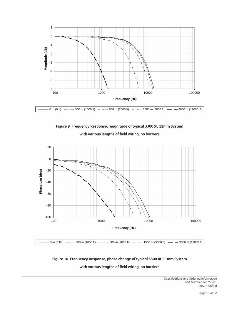
Figure 9 Frequency Response, magnitude of typical 3300 XL 11mm System
with various lengths of field wiring, no barriers
Figure 10 Frequency Response, phase change of typical 3300 XL 11mm System
with various lengths of field wiring, no barriers
-6
-5
-4
-3
-2
-1
0
1
100 1000 10000 100000
Mag
nitu
de (d
B)
Frequency (Hz)
0 m (0 ft) 300 m (1000 ft) 600 m (2000 ft) 1500 m (5000 ft) 3600 m (12000 ft)
-100
-80
-60
-40
-20
0
20
100 1000 10000 100000
Phas
e La
g (d
eg)
Frequency (Hz)
0 m (0 ft) 300 m (1000 ft) 600 m (2000 ft) 1500 m (5000 ft) 3600 m (12000 ft)

Specifications and Ordering Information Part Number 146256-01
Rev. F (08/14)
Page 19 of 22
Figure 11 3300 XL 11 mm Proximity probes, Standard Mount 330701, ½-20 UNF-2A, without armor
330702, ½-20 UNF-2A, with armor
330703, M14X1.5 thread, without armor
330704, M14X1.5 thread, with armor
330707, 5/8-18 UNF-2A, without armor
330708, 5/8-18 UNF-2A, with armor
330709, M16X1.5 thread, without armor
330710, M16X1.5 thread, with armor
Figure 12 Installed Connector Protectors
Safety Wire HolesHex Nut with Wrench Flats
(0.42)
8.4 (0.33) Max.Case Length "B"
10.7
Probe Tip
Total Length "C", +30%, -0%
ThreadCase 3.7 (0.15) Max. Outside Dia.
75 ohm Cable
Coaxial ConnectorMiniature Male
7.23 (0.285) OutsideDia. Maximum "D"
7.6 (0.30) Max. Outside Dia. of Armor
Unthreaded Length "A"
2.5 (0.10)
Dia. Max.3.9 (0.16) Max. Dia. for FluidLoc CableR

Specifications and Ordering Information Part Number 146256-01
Rev. F (08/14)
Page 20 of 22
Figure 13 3300 XL 11 mm Proximity Probes, Reverse Mount
330705, 3/8-24 UNF-2A threads
330706, M10X1 threads
Figure 14 330730, 3300 XL 11 mm Extension Cable
(0.42)
8.4 (0.33) Max.
Case Length "B"
10.7
Probe Tip
Unthreaded Length "A"
Total Length "C", +30%, -0%
7/16 or 12mmHex Thread
Case
3.7 (0.15) outside Dia.75 ohm Cable
Coaxial ConnectorMiniature Male
7.23 (0.285) OutsideDia. Maximum "D"
Dia. Max.
21.6 (0.85)
46 (1.8)
5.0 (0.20)
Safety Wire HolesHex Nut with Wrench Flats
(0.42)
8.4 (0.33) Max.Case Length "B"
10.7
Probe Tip
Total Length "C", +30%, -0%
ThreadCase 3.7 (0.15) Max. Outside Dia.
75 ohm Cable
Coaxial ConnectorMiniature Male
7.23 (0.285) OutsideDia. Maximum "D"
7.6 (0.30) Max. Outside Dia. of Armor
Unthreaded Length "A"
2.5 (0.10)
Dia. Max.3.9 (0.16) Max. Dia. for FluidLoc CableR

Specifications and Ordering Information Part Number 146256-01
Rev. F (08/14)
Page 21 of 22
Figure 15 Panel Mount 3300 XL 11 mm Proximitor* Sensor
Figure 16 DIN Mount 3300 XL 11 mm ProximitorSensor
Mounting Option
"A" Options -50 or -90
63.5 (2.50)
50.8 (2.00)
81.3 (3.20)
50.8 (2.00)
61.2 (2.41)
5.1 (0.20)
(0.158) 4.0
DIA
70.8 (2.79)
89.4 (3.52) 31.7 (1.25) [Additional
3.05 (0.120) clearance required to remove DIN rail]
Mounting Option "A" Options -51 or -91
35mm DIN rail (not included)
Specifications and Ordering Information Part Number 146256-01
Rev. F (08/14)
Page 22 of 22
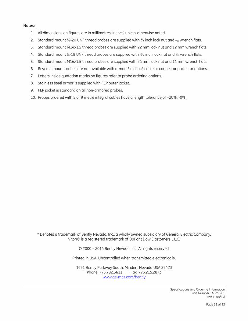
Notes:
1. All dimensions on figures are in millimetres (inches) unless otherwise noted.
2. Standard mount ½-20 UNF thread probes are supplied with ¾ inch lock nut and 7⁄16 wrench flats.
3. Standard mount M14x1.5 thread probes are supplied with 22 mm lock nut and 12 mm wrench flats.
4. Standard mount 5⁄8-18 UNF thread probes are supplied with 15⁄16 inch lock nut and 9⁄16 wrench flats.
5. Standard mount M16x1.5 thread probes are supplied with 24 mm lock nut and 14 mm wrench flats.
6. Reverse mount probes are not available with armor, FluidLoc* cable or connector protector options.
7. Letters inside quotation marks on figures refer to probe ordering options.
8. Stainless steel armor is supplied with FEP outer jacket.
9. FEP jacket is standard on all non-armored probes.
10. Probes ordered with 5 or 9 metre integral cables have a length tolerance of +20%, -0%.
* Denotes a trademark of Bently Nevada, Inc., a wholly owned subsidiary of General Electric Company. Viton® is a registered trademark of DuPont Dow Elastomers L.L.C.
© 2000 – 2014 Bently Nevada, Inc. All rights reserved.
Printed in USA. Uncontrolled when transmitted electronically.
1631 Bently Parkway South, Minden, Nevada USA 89423
Phone: 775.782.3611 Fax: 775.215.2873 www.ge-mcs.com/bently