321 a. m. ahmed et al, static behaviour of different types ... · ... ( rc ) beam-column joints....
TRANSCRIPT
A. M. Ahmed et al, Static Behaviour of Different Types of R.C Beam-Column Connections as
Affected by Both Value of Acting Axial Normal Force and Grade of Used Concrete (Theoretical
Study) , pp. 321- 364
* Corresponding author.
Civil Engineering Department, Faculty of Engineering, Assiut University
321
STATIC BEHAVIOUR OF DIFFERENT TYPES OF R.C BEAM-
COLUMN CONNECTIONS AS AFFECTED BY BOTH VALUE OF ACTING AXIAL NORMAL FORCE AND GRADE
OF USED CONCRETE (THEORETICAL STUDY)
Abdel Rahman M. Ahmed 1, Mohamed M. Rashwan 2 and Lamiaa K. Idriss 3, *
Staff in Civil Engineering Department, Faculty of Engineering, Assiut University
Received 11 November 2012; accepted 30 November 2012
ABSTRACT
This paper describes a theoretical study of the effect of both acting axial loads and grade of concrete
on the static behaviour of (32) thirty two Reinforced Concrete (RC) Beam-column joints.
ABAQUS\CAE version 6.7, a nonlinear finite element analysis software package, was developed
specifically for the analysis of reinforced concrete structures under plane stress conditions. Variable
axial loads were applied and increased gradually with constant lateral load, which was applied
maintaining at the top of the column at internal and external beam-column joint only the ultimate
and cracking axial loads were recorded as well as the corresponding versus vertical displacement,
the maximum joint shear stresses, axial, stresses strains, and absorbed energy, mode of failure using
different grades of concrete C250, C400, C600 and C1200 were evaluated and recorded.
Keywords: Column axial load, RC beam column connection, energy absorption, ABAQUS\ CAE, concrete
compressive strength, shear stress, ultimate, cracking load and energy absorption.
1. Introduction
Chris P. et al., (2002); suggests limiting experimental evidence that increasing the
column axial load tends to reduce the total lateral drift at yield (Kurose 1987). Although
some researchers reported that increasing column axial load results in increasing shear
strength of joints without reinforcement, the data do not show a significant trend (Beres et
al., 1992). Because of the binding of the profile steel and stirrups, the axial pressure makes
the concrete of the core area in the three dimensions, stress state which inhibits the
cracking of concrete. Also, after the cracking of concrete, the axial pressure makes the
larger mechanical friction formed between the concrete blocks, so that a moderate axial
compression ratio can enhance the shear strength of the joints. However, if the axial
pressure exceeds the critical value, the concrete will be crushed, and the shear strength will
be reduced (Xiaoli Yang 2009). Bing Li, et al., (2003), have already investigated the
influence of axial loading on the seismic behavior of beam- wide column joints, it can be
seen that when axial load increased from 0 to 0.2 f'cAg the number of cycles increased
correspondingly so the joints without transverse reinforcement are easily overloaded and
failed at an earlier ductility level stage.
The ultimate load obtained and suggested by BS8110 for interior joint is given by
following Equation:
Nu= 0.45 ƒcu Ac+ 0.95 ƒ`yAst (1)

A. M. Ahmed et al, Static Behaviour of Different types of R.C Beam-Column Connections as
Affected by Both Value of Acting Axial Normal Force and Grade of Used Concrete (Theoretical
Study), pp. 321- 364
Journal of Engineering Sciences, Assiut University, Faculty of Engineering, Vol. 41, No. 2, March,
2013, E-mail address: [email protected]
322
Kumar et. al., ( 2002) found that both the joint rotation and the axial load in the
column increase the ductility and energy dissipation capacity and reduced the joint region
damage (Xiaoli Yang 2009). Changing cross section of columns, the eccentric axial force
forms, which will cause the stress of the joint area to superimpose. The stiffness, ductility
and the energy dissipation performance of the overall joint will be decreased with the
increase of eccentric bending moment.
More recently (S. R. Uma 2006), have shown the effect of axial load on nominal shear
stress. In recent research publications (Hakuto et al., 2000) the significance of
representing joint capacity in terms of principal stresses has been discussed, which
recognizes the axial load acting on the column. A critical situation where the axial load on
the column is very large, diagonal compression failure of strut occurring before the first
diagonal tensile cracking in the joint has been cautioned. Therefore, it is very essential to
account for the axial load effect in limiting the joint nominal shear stress. Paul S. et al.,
(2000) study; the effect of the column load on ultimate capacity, with the axial load shown
as an approximate equivalent concrete stress by simply dividing by the area of the column.
For all arrangements increasing the column load, up to a value of approximately 20 MPa,
increases the ultimate capacity of the joint. At column loads above 20 MPa (l/3fcu), the
combined stresses reduce the ultimate capacity of the joint.
Increasing the column load stiffens of the joint and improves the effectiveness of the
anchorage transfer along the initial part of the reinforcing bar by pinching the bar. The
increase in the ultimate capacity of the joint is due to the higher stiffness compares the
code provisions for nominal shear stress for varying axial load ratios for both interior and
exterior joints. It can be seen that ACI318M-(2002) code allows higher nominal shear
stress and NZS 3101 (1995) code limits to a lesser value, and both are not affected by axial
loads. On the other hand, limiting value of nominal shear stress as per EN3101 (1995)
code decreases as the axial load increases, especially for exterior joints, where the variation
of axial loads acting on the column could be high during seismic event.
To investigate and compare the behaviors of joint specimens with the proposed detail
on 32 joints, the normal-strength and high-strength test specimens are both representative
of an interior, and exterior joint specimens with constant lateral load ,variable compressive
axial load at the top of the column were applied until it failed for the purposed of studying
cracking, ultimate axial load, the maximum joint shear stresses and total absorbed energy
for different grades of concrete C250, C400, C600, and C1200.
2. Details of RC joints
Table 1 includes the data of the connection between the main beam, column, and slab.
Thirty two (32) Joints were taken into account. Beam size for all joints of (bb×db) mm is
(250 mm wide by 300 mm deep) mm as well as column size of (bc×dc) mm is (300×300
mm)were kept constant.
The total height of the columns above and below the joint was the same for both
specimens at H=2.0 m, length of beam right and left the joint L=3.0m, which gave L\2=1.5
m. The floor slabs for both specimens were of equal sizes, with a thickness ts of 120 mm.

A. M. Ahmed et al, Static Behaviour of Different types of R.C Beam-Column Connections as
Affected by Both Value of Acting Axial Normal Force and Grade of Used Concrete (Theoretical
Study), pp. 321- 364
Journal of Engineering Sciences, Assiut University, Faculty of Engineering, Vol. 41, No. 2, March,
2013, E-mail address: [email protected]
323
The boundary conditions, beam ends were supported by horizontal rollers, while the
bottom of the column was supported by a mechanical hinge constant too, All the joints
were chosen to have concrete of specified characteristic cube strength (ƒc'), of 250–400–600–1200 kg/cm
2, and yield stress for reinforcing bar (ƒy) 2400–2800–3600–4000 kg/cm
2
respectively.
The reinforcement details of all the specimens were identical as shown in Fig. 1.a for
interior joint, and Figure 1.b for exterior joint ,where the beam was equally reinforced at
the top and bottom by four high-yield deformed bars of 16 mm diameter Abs (i.e. 416,
416).
Stirrups (ρw) from 6 mm-diameter mild steel, bars with specified characteristic yield
strength of 2400 kg/cm2 were provided at 80 mm spacing (i.e. 6@80 stirrups). The
column contained (Acs) 12 16 longitudinal reinforcing bars distributed around the
perimeter. The transverse reinforcement in the column comprised 6 square hoops and 6
cross ties in two perpendicular directions at 80 mm spacing, as shown in Table 1 and Fig.1.
3. Mesh arrangement:
The mesh module allows to generate meshes at Fig.2 on assemblies created with
ABAQUS\CAE various levels of automation and control are available so that you can
create a mesh that meets the needs of your analysis. Mesh refinement is required. When
severely nonlinear material Models are used, however, increasing the number of element
can increasing constrains within the model. This reduces hear deformation that can lead to
an overlay stiff load deflection response (Abaqus. 2000).
4. Boundary conditions and applied loadings:
The loadings set up are shown in Figures 3.a, 3.b, for interior and exterior joint. The
specimens were supported in vertical position. Statically cyclic lateral load was applied
maintaining variable axial load at the top of the column for interior and exterior joint only
so as knee joint has no axial load. The top of the column was loaded by two actuators in
vertical and horizontal directions. The beam ends were supported by horizontal rollers,
while the bottom of the column was supported by a mechanical hinge. The distances
between two loading points for beams and columns are shown in Fig. 3.

A. M. Ahmed et al, Static Behaviour of Different types of R.C Beam-Column Connections as
Affected by Both Value of Acting Axial Normal Force and Grade of Used Concrete (Theoretical
Study), pp. 321- 364
Journal of Engineering Sciences, Assiut University, Faculty of Engineering, Vol. 41, No. 2, March,
2013, E-mail address: [email protected]
324
Table 1 Properties of joints.
Type of beam-column
joints
Interior joint
Exterior joint
(a) Beam (bbdb) mm (250300) (250300)
Top bars 4 16 416
at mm² 804 804
pt % 1.18 1.18
Bot. bars 4 16 416
at mm² 804 804
t % 1.18 1.18
Stirrups 2 6 2 6
@ (mm) 80 80
w% 0.64 0.64
(b) column (bcdc) mm (300300) (300300)
Total Bars 12 16 12 16
ag mm² 2412 2412
g% 2.62 2.62
Hoops 2 6 2 6
@ (mm) 80 80
w% 0.27 0.27
(c) connection HL mm (20003000) (20001500)
Hoops 26 26
Sets 3 @ 60 3 @ 60
aw mm2 192 192
w% 0.38 0.38
Shape Closed Closed
(d) Slabs thick 12 12
Longitudinal Dir 24 8 24 8
@ (mm) 100 100
Stirrups ratio % 0.38 0.38
Transverse Dir. 24 8 24 8
@ (mm) 200 200
Stirrups ratio % 0.27 0.27 Note: at: total area of tensile reinforcement, t: tensile reinforcement ratio, ag: total area of longitudinal reinforcement,
g: gross reinforcement ratio, aw: total area of web reinforcement placed between top and bottom beam bars, ρw: web
reinforcement ratio, Ec = 14000√ ƒc kg/cm2, Es = 2.2×10⁶ kg/cm2ƒy: yield strength, ƒc: concrete compressive strength,
ƒt: concrete tensile strength.

A. M. Ahmed et al, Static Behaviour of Different types of R.C Beam-Column Connections as Affected by Both Value of Acting Axial Normal Force
and Grade of Used Concrete (Theoretical Study), pp. 321- 364
Journal of Engineering Sciences, Assiut University, Faculty of Engineering, Vol. 41, No. 2, March, 2013, E-mail address: [email protected]
325
Compressive cube strength of
concrete (ƒc')\kg/cm2
Column axial force (Nc) (Ton)
Yield strength of steel
reinforcement (fy) kg/cm2
Kind of joint
Interior joint
Exterior joint
Area of column bcdc mm (Ac) cm2
Area of connection HL mm (Aj) cm2
Transfer reinforcement ratio (pw%)
Top and bottom reinforcements of
beam (As1, As2) cm2
Area of the column reinforcement (Acs)
End boundary condition
Constant given
Variable given
Given Data
Area of beam bbdb (Ab) cm2
Column shear force (Vc) (Ton)

A. M. Ahmed et al, Static Behaviour of Different types of R.C Beam-Column Connections as
Affected by Both Value of Acting Axial Normal Force and Grade of Used Concrete (Theoretical
Study), pp. 321- 364
Journal of Engineering Sciences, Assiut University, Faculty of Engineering, Vol. 41, No. 2, March,
2013, E-mail address: [email protected]
326
Joint shear
stress (J)
kg/cm2
Principle axial
stress (1)
kg/cm2
Principle axial
strain (1)
cm/cm
Axial top
displacement (v)
mm
Cracking axial
load (Ncc)
Ton
Ultimate axial
load (Ncu)
Ton
Results
Absorbed
Energy (E.A.)
Tonmm
Joint bond
stress (B)
kg/cm2

A. M. Ahmed et al, Static Behaviour of Different types of R.C Beam-Column Connections as
Affected by Both Value of Acting Axial Normal Force and Grade of Used Concrete (Theoretical
Study), pp. 321- 364
Journal of Engineering Sciences, Assiut University, Faculty of Engineering, Vol. 41, No. 2, March,
2013, E-mail address: [email protected]
327
a) Reinforcement details of interior beam-column joint specimens
b) Reinforcement details of exterior beam-column joint specimens
Fig. 1. The reinforcement details of all the specimens

A. M. Ahmed et al, Static Behaviour of Different types of R.C Beam-Column Connections as
Affected by Both Value of Acting Axial Normal Force and Grade of Used Concrete (Theoretical
Study), pp. 321- 364
Journal of Engineering Sciences, Assiut University, Faculty of Engineering, Vol. 41, No. 2, March,
2013, E-mail address: [email protected]
328
a) 3D view of meshed interior joint
b) 3D view of meshed exterior joint
Fig. 2. 3 D view of meshed joint

A. M. Ahmed et al, Static Behaviour of Different types of R.C Beam-Column Connections as
Affected by Both Value of Acting Axial Normal Force and Grade of Used Concrete (Theoretical
Study), pp. 321- 364
Journal of Engineering Sciences, Assiut University, Faculty of Engineering, Vol. 41, No. 2, March,
2013, E-mail address: [email protected]
329
a) interior joint
b) exterior joint
Fig. 3. The loading set up and Boundary condition of joints
The modifications were based on nonlinearity analytically model carried out by (Sam
Lee 2008) The degradation factors for compression (dc) and tension (dt) are dependent on
the plastic strain (ABAQUS, V6.5).
A. M. Ahmed et al, Static Behaviour of Different types of R.C Beam-Column Connections as
Affected by Both Value of Acting Axial Normal Force and Grade of Used Concrete (Theoretical
Study), pp. 321- 364
Journal of Engineering Sciences, Assiut University, Faculty of Engineering, Vol. 41, No. 2, March,
2013, E-mail address: [email protected]
330
The nonlinearity of the structure includes geometry nonlinearity, material nonlinearity
and a combination of both.
5. Geometry nonlinearity:
Geometry nonlinearity can be modeled accurately by use of the Green strain formula.
The P-Δ effects and large deflection effects are automatically taken into account. εost general finite element analysis packages have this built-in function available.
6. Material nonlinearity:
Steel and concrete are the basic materials used in the structural elements. To model the
cyclic characteristics of the earthquake load, a nonlinear material model with specific
cyclic features should be used for each.
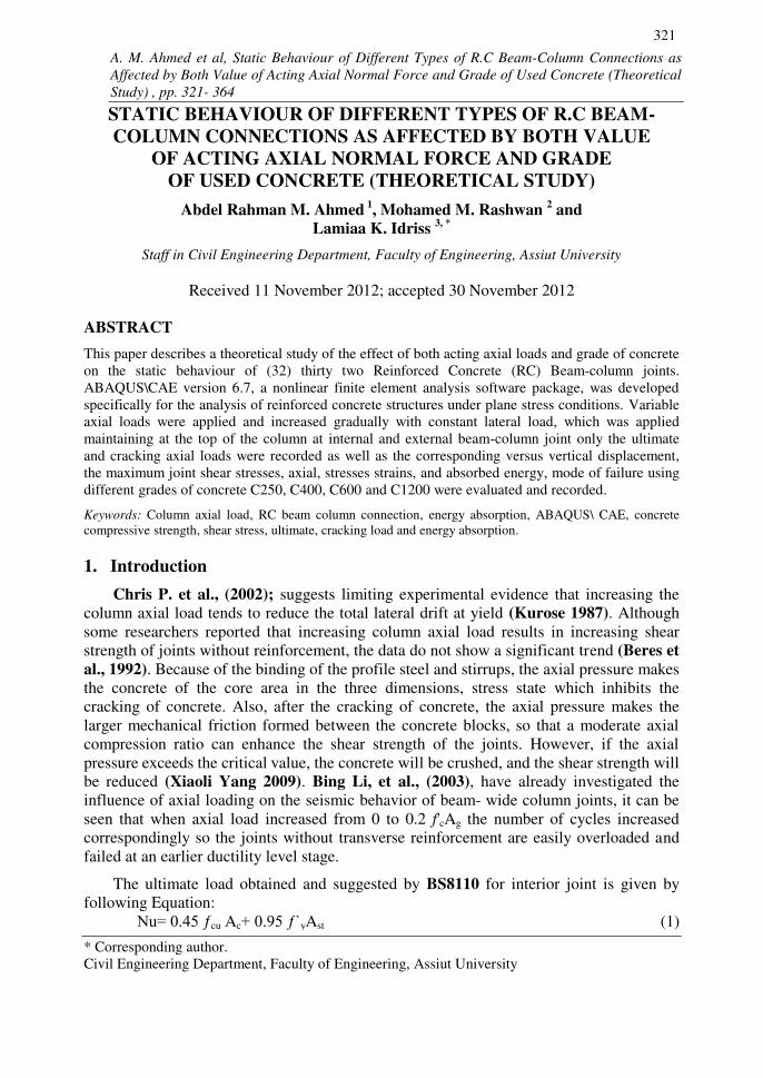
Steel
Fig. 4. Steel constitute law
In this article, an isotropic kinematics hardening model is used for steel material. As
shown in Figure 4, the blushing effect has been taken into account, and there is no stiffness
degradation during the cycling. It is acceptable for the skyscraper structure as the
maximum steel strain should be less than 2.5%.
Concrete: The plastic-damage model (J. Lee, 1998) is used to model the concrete material. The
model is a continuum, plasticity-based, damage model for concrete. It assumes that the
main two failure mechanisms are tensile cracking and compressive crushing of the
concrete material. It captures the three major characteristics of the concrete in the
buildings: (1) the strength of compression is larger than that of tension; (2) the
stiffness degrades when it goes into plastic range; (3) the stiffness recovers when it
reverses from tension to compression.

A. M. Ahmed et al, Static Behaviour of Different types of R.C Beam-Column Connections as
Affected by Both Value of Acting Axial Normal Force and Grade of Used Concrete (Theoretical
Study), pp. 321- 364
Journal of Engineering Sciences, Assiut University, Faculty of Engineering, Vol. 41, No. 2, March,
2013, E-mail address: [email protected]
331
Fig. 5. Concrete in tension (Sam Lee 2008)
Fig. 6. Concrete in compression (Sam Lee 2008)
Figure 5 and Figure 6 show the concrete material’s stress-strain curve, the stiffness of
the concrete degrades when it unloads from the plastic range. The degradation factors for
compression (dc) and tension (dt) are dependent on the plastic strain (ABAQUS, V6.5).
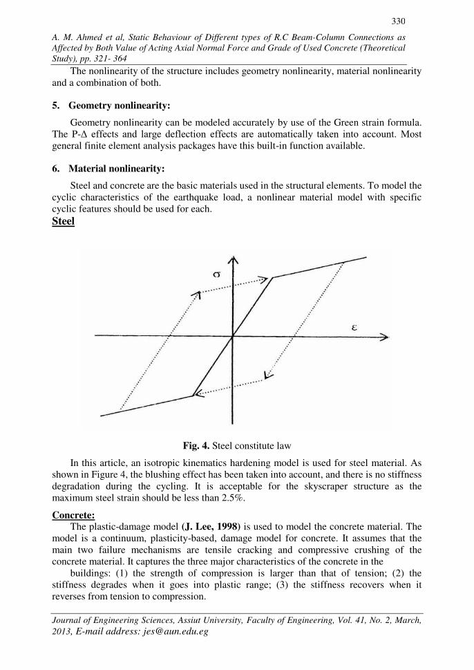
Figure 7 shows the hysteric curve of the concrete, it can be seen that the stiffness recovers
when the material stress status reverses from tension to compression.
A. M. Ahmed et al, Static Behaviour of Different types of R.C Beam-Column Connections as
Affected by Both Value of Acting Axial Normal Force and Grade of Used Concrete (Theoretical
Study), pp. 321- 364
Journal of Engineering Sciences, Assiut University, Faculty of Engineering, Vol. 41, No. 2, March,
2013, E-mail address: [email protected]
332
Fig. 7. Concrete hysteric curve (Sam Lee 2008)
In the fixed crack model, the crack direction is determined and fixed at the time of
crack initiation. In the rotating crack model .The crack direction is identical with a
principal strain direction and rotates if the strain direction changes. The main difference in
these crack models is the absence of shear stresses on the crack plane in the rotating crack
model due coincidence of principal strain directions with the crack orientation, which
makes the rotating crack model more simple. In the fixed crack model the shear resistance
of the cracks is modeled by means of the variable shear retention factor, which reflects the
aggregate interlock effect of cracked concrete. Concrete in plane stress condition can be
well described by a damage model such as the one used in the ABAQUS, see Fig. 8. It is
based on the “equivalent uniaxial law”, which covers the complete range of the plane stress behaviour in tension and compression. The effect of biaxial stress state on the concrete
strength is captured by the failure function due to (Kupfer et al., 2011). For the tensile
response (cracking) the crack band method described above is applied. Similar method is
applied for the compressive softening. Thus complete softening behaviour is based on an
objective and mesh independe1nt approach.
7. Data given and obtained results
The loading set up, specimens statically cyclic lateral load was applied maintaining
variable axial load at the top of the column for interior and exterior joint only so as knee
joint has no axial load were supported in vertical position. To investigate the influence of
concrete compressive strength on the seismic behavior of interior, exterior beam column
joints under different axial loading levels were analyzed by the FEM software
ABAQUS\CAE and corresponding story shear force versus horizontal displacement.

A. M. Ahmed et al, Static Behaviour of Different types of R.C Beam-Column Connections as
Affected by Both Value of Acting Axial Normal Force and Grade of Used Concrete (Theoretical
Study), pp. 321- 364
Journal of Engineering Sciences, Assiut University, Faculty of Engineering, Vol. 41, No. 2, March,
2013, E-mail address: [email protected]
333
Fig. 8. Equivalent uniaxial law
Bi-axial failure function by Kupfer 2011
With different applied axial loads at which ultimate and cracking axial load was
accrued, the maximum joint shear stresses observed, absorbed energy, failure mode
several linear variable displacement transducers were mounted on the test specimens to
measure the net story drift, joint rotation, gap openings, and shear deformations, the net
column top displacement (Δh) was calculated by subtracting the column base lateral
displacement from the lateral displacement measurement at the column top.
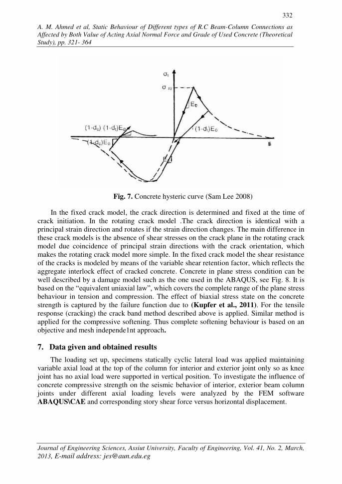
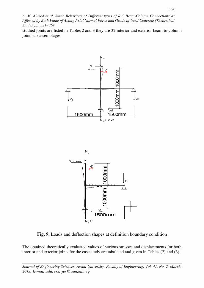
Figure 9 shows modeling connections with loading and boundary condition and
deflection shapes studying by ABAQUS\CAE 6.7 software for interior, exterior joints. The
A. M. Ahmed et al, Static Behaviour of Different types of R.C Beam-Column Connections as
Affected by Both Value of Acting Axial Normal Force and Grade of Used Concrete (Theoretical
Study), pp. 321- 364
Journal of Engineering Sciences, Assiut University, Faculty of Engineering, Vol. 41, No. 2, March,
2013, E-mail address: [email protected]
334
studied joints are listed in Tables 2 and 3 they are 32 interior and exterior beam-to-column
joint sub assemblages.
Fig. 9. Loads and deflection shapes at definition boundary condition
The obtained theoretically evaluated values of various stresses and displacements for both
interior and exterior joints for the case study are tabulated and given in Tables (2) and (3).

A. M. Ahmed et al, Static Behaviour of Different types of R.C Beam-Column Connections as Affected by Both Value of Acting Axial Normal Force
and Grade of Used Concrete (Theoretical Study), pp. 321- 364
Journal of Engineering Sciences, Assiut University, Faculty of Engineering, Vol. 41, No. 2, March, 2013, E-mail address: [email protected]
335
Table 2
Obtained theoretical results for studied interior beam-column joints.
Joint No.
Compressive
concrete
(fc`)(kg/cm2)
Yield
strength ( fy)
(kg/cm2)
Lateral
load (ton)
(Vc)
Axial
load (ton)
(Nc)
Nc / (fc) Ac
Top Axial
Displacement
mm(v)
Max. principle
stress
(kg/cm2) (1)
Joint shear
stress
(kg/cm2) (J)
Max.
principle
strain cm/cm
(1 ×10⁻⁴)
Energy
Absorption E.A
(Ton×mm)
J (1) 250 2400 0 0 0 0 0 62.23 0 0
J (2) 250 2400 50 65 0.28 12 97.60 80.04 2.36 1382
J (3) 250 2400 50 115 0.52 20.23 96.38 79.44 2.33 2300
J (4) 250 2400 50 131 0.58 24.50 95.16 78.55 2.85 2764
J (5) 400 2800 0 0 0 0 0 80.4 0 0
J (6) 400 2800 50 100 0.27 20.80 123.75 99.31 3.05 2150
J (7) 400 2800 50 177 0.49 34.50 122 98.86 2.96 3978
J (8) 400 2800 50 187 0.52 40.22 120 96.50 3.66 4730
J (9) 600 3600 0 0 0 0 0 100.55 0 0
J (10) 600 3600 50 120 0.22 25.20 168 129.12 4.10 2886
J (11) 600 3600 50 218 0.41 37.20 166 128.76 4.05 3930
J (12) 600 3600 50 254 0.47 44.08 164 128.30 4.70 5080
J (13) 1200 4000 0 0 0 0 0 142.90 0 0
J (14) 1200 4000 50 200 0.18 40.00 218 162 5.87 6000
J (15) 1200 4000 50 398 0.36 58.20 215 161.63 5.70 8701
J (16) 1200 4000 50 452 0.42 65 211 161.42 6.10 9752
A. M. Ahmed et al, Static Behaviour of Different types of R.C Beam-Column Connections as Affected by Both Value of Acting Axial Normal Force
and Grade of Used Concrete (Theoretical Study), pp. 321- 364
Journal of Engineering Sciences, Assiut University, Faculty of Engineering, Vol. 41, No. 2, March, 2013, E-mail address: [email protected]
336
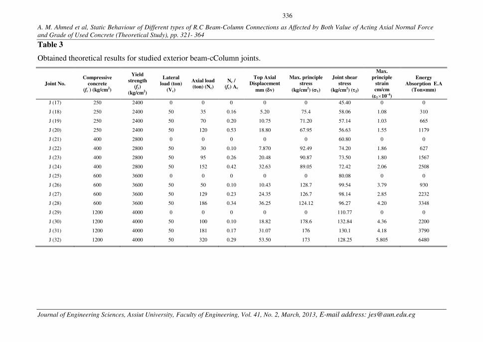
Table 3
Obtained theoretical results for studied exterior beam-cColumn joints.
Joint No.
Compressive
concrete
(fc`) (kg/cm2)
Yield
strength (fy)
(kg/cm2)
Lateral
load (ton)
(Vc)
Axial load (ton) (Nc)
Nc / (fc) Ac
Top Axial Displacement
mm (v)
Max. principle stress
(kg/cm2) (1)
Joint shear stress
(kg/cm2) (J)
Max.
principle strain
cm/cm
(1 10–4)
Energy
Absorption E.A
(Ton×mm)
J (17) 250 2400 0 0 0 0 0 45.40 0 0
J (18) 250 2400 50 35 0.16 5.20 75.4 58.06 1.08 310
J (19) 250 2400 50 70 0.20 10.75 71.20 57.14 1.03 665
J (20) 250 2400 50 120 0.53 18.80 67.95 56.63 1.55 1179
J (21) 400 2800 0 0 0 0 0 60.80 0 0
J (22) 400 2800 50 30 0.10 7.870 92.49 74.20 1.86 627
J (23) 400 2800 50 95 0.26 20.48 90.87 73.50 1.80 1567
J (24) 400 2800 50 152 0.42 32.63 89.05 72.42 2.06 2508
J (25) 600 3600 0 0 0 0 0 80.08 0 0
J (26) 600 3600 50 50 0.10 10.43 128.7 99.54 3.79 930
J (27) 600 3600 50 129 0.23 24.35 126.7 98.14 2.85 2232
J (28) 600 3600 50 186 0.34 36.25 124.12 96.27 4.20 3348
J (29) 1200 4000 0 0 0 0 0 110.77 0 0
J (30) 1200 4000 50 100 0.10 18.82 178.6 132.84 4.36 2200
J (31) 1200 4000 50 181 0.17 31.07 176 130.1 4.18 3790
J (32) 1200 4000 50 320 0.29 53.50 173 128.25 5.805 6480
A. M. Ahmed et al, Static Behaviour of Different types of R.C Beam-Column Connections as
Affected by Both Value of Acting Axial Normal Force and Grade of Used Concrete (Theoretical
Study), pp. 321- 364
Journal of Engineering Sciences, Assiut University, Faculty of Engineering, Vol. 41, No. 2, March,
2013, E-mail address: [email protected]
337
Top vertical displacement mm(v)
Axia
l co
lum
n l
oa
ds
ton (
Nc)
fy =2400kg/cm2
fy =2800kg/cm2
fy =3600kg/cm2 fy =4000kg/cm
2
Top vertical displacement mm(v)
Axia
l co
lum
n l
oa
ds
ton (
Nc)
fy =2400kg/cm2
fy =2800kg/cm2
fy =3600kg/cm2 fy =4000kg/cm
2
The effects of the most of parameters, which may influence the behavior of beam-column
joint are evaluated and can be represented by the following relationships:
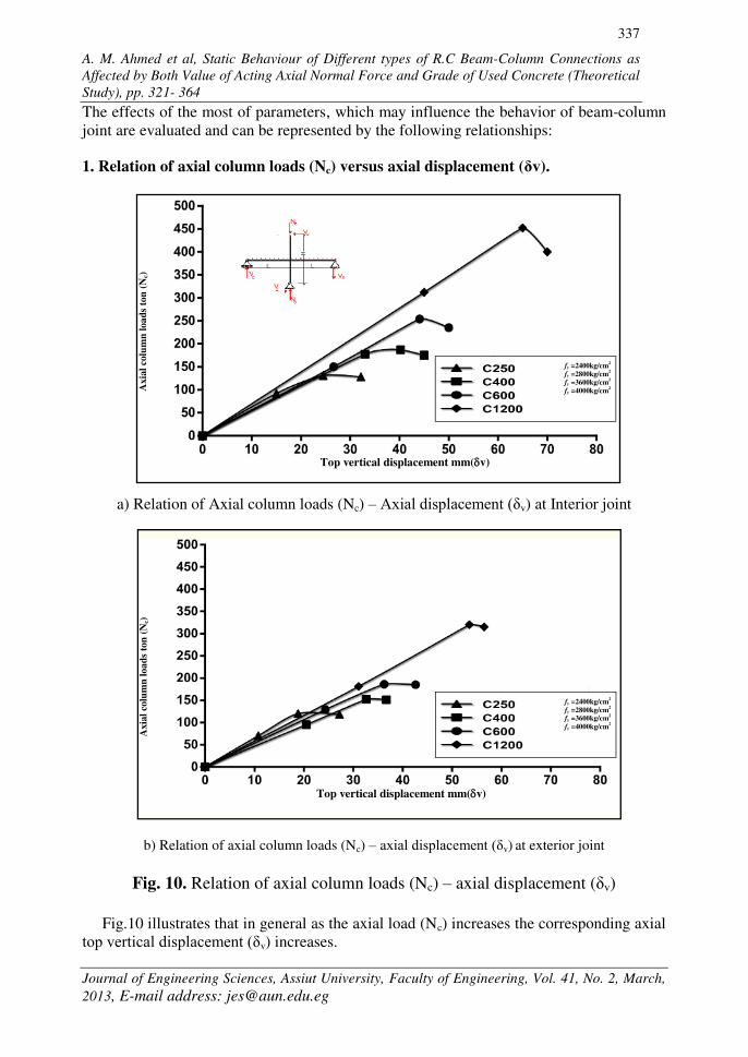
1. Relation of axial column loads (Nc) versus axial displacement ( v).
a) Relation of Axial column loads (Nc) – Axial displacement ( v) at Interior joint
b) Relation of axial column loads (Nc) – axial displacement ( v) at exterior joint
Fig. 10. Relation of axial column loads (Nc) – axial displacement ( v)
Fig.10 illustrates that in general as the axial load (Nc) increases the corresponding axial
top vertical displacement ( v) increases.
A. M. Ahmed et al, Static Behaviour of Different types of R.C Beam-Column Connections as
Affected by Both Value of Acting Axial Normal Force and Grade of Used Concrete (Theoretical
Study), pp. 321- 364
Journal of Engineering Sciences, Assiut University, Faculty of Engineering, Vol. 41, No. 2, March,
2013, E-mail address: [email protected]
338
Axial load ratio (Nc\AcFc%)
Sh
ear
stre
ss (
τ J)
kg/c
m2
fy =2400kg/cm2
fy =2800kg/cm2
fy =3600kg/cm2 fy =4000kg/cm
2
Axial load ratio (Nc\AcFc%)
Sh
ear
stre
ss (
τ J)
kg
/cm
2
fy =2400kg/cm2
fy =2800kg/cm2
fy =3600kg/cm2 fy =4000kg/cm
2
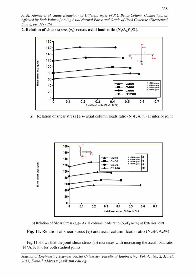
2. Relation of shear stress (τJ) versus axial load ratio (Nc\Acc%).
a) Relation of shear stress (τJ)– axial column loads ratio (Nc\FcAc%) at interior joint
b) Relation of Shear Stress (τJ)– Axial column loads ratio (Nc\FcAc%) at Exterior joint
Fig. 11. Relation of shear stress (τJ) and axial column loads ratio (Nc\FcAc%)
Fig.11 shows that the joint shear stress (τJ) increases with increasing the axial load ratio
(Nc\AcFc%), for both studied joints.

A. M. Ahmed et al, Static Behaviour of Different types of R.C Beam-Column Connections as
Affected by Both Value of Acting Axial Normal Force and Grade of Used Concrete (Theoretical
Study), pp. 321- 364
Journal of Engineering Sciences, Assiut University, Faculty of Engineering, Vol. 41, No. 2, March,
2013, E-mail address: [email protected]
339
Sh
ear
Str
ess
kg/c
m2
(τJ)
Principle axial stress kg/cm-2 (1)
fy =2400kg/cm2
fy =2800kg/cm2
fy =3600kg/cm2 fy =4000kg/cm
2
Principle axial stress kg/cm-2 (1)
Sh
ear
Str
ess
kg/c
m2 (τ
J)
fy =2400kg/cm2
fy =2800kg/cm2
fy =3600kg/cm2 fy =4000kg/cm
2
3. Relation of shear stress (τJ) kg/cm2–principle axial Stress (1) kg/cm2 Fig. (12)
a) Relation of shear Stress (τJ)–a principle axial stress (1) kg/cm2 for Interior Joint
b) Relation of shear Stress (τJ)–a Principle axial stress (1) kg/ cm2 at exterior joint
Fig. 12. Relation of shear stress (τJ) and a principle axial stress (1)
Fig.12 illustrates that in general as the axial stress (1) increases the corresponding shear
stress (τJ) also increases approximately in linear relationship of constant rate disregarding the
grade of concrete.

A. M. Ahmed et al, Static Behaviour of Different types of R.C Beam-Column Connections as
Affected by Both Value of Acting Axial Normal Force and Grade of Used Concrete (Theoretical
Study), pp. 321- 364
Journal of Engineering Sciences, Assiut University, Faculty of Engineering, Vol. 41, No. 2, March,
2013, E-mail address: [email protected]
340
En
ergy A
bso
rpti
on
(to
n
mm
)
Top Axial displacement mm(v)
fy =2400kg/cm2
fy =2800kg/cm2
fy =3600kg/cm2 fy =4000kg/cm
2
Top Axial displacement mm(v)
En
erg
y A
bso
rpti
on
(to
nm
m)
fy =2400kg/cm2
fy =2800kg/cm2
fy =3600kg/cm2 fy =4000kg/cm
2
4. Relation of energy absorption (E.A)–vertical top displacement ( v)
a) Relation of energy absorption (E.A)–vertical top displacement ( v) for interior joint
b) Relation of energy absorption (E.A)–vertical top displacement ( v) at exterior joint
Fig. 13. Relation of energy absorption (E.A) versus vertical top displacement ( v)
Fig.13 illustrates that in general as vertical top displacement ( v) increases the energy
absorption increases too, a nearly linear relationship with respect to the vertical top
displacement for various levels energy absorption.

A. M. Ahmed et al, Static Behaviour of Different types of R.C Beam-Column Connections as
Affected by Both Value of Acting Axial Normal Force and Grade of Used Concrete (Theoretical
Study), pp. 321- 364
Journal of Engineering Sciences, Assiut University, Faculty of Engineering, Vol. 41, No. 2, March,
2013, E-mail address: [email protected]
341
Max. principle stress kg\cm2 (1)
Max.
pri
nci
ple
str
ain
cm
/cm
(1
)1
0–4
fy =2400kg/cm2
fy =2800kg/cm2
fy =3600kg/cm2 fy =4000kg/cm
2
Max. principle stress kg\cm2 (1)
Max.
pri
nci
ple
str
ain
cm
/cm
( 1
)1
0–4
fy =2400kg/cm2
fy =2800kg/cm2
fy =3600kg/cm2 fy =4000kg/cm
2
5. Relation of max. principle stress (1) – maximum principle strain ( 1)
a) Relation of max. principle stress (1)- max. principle strain ( 1) for interior joint
b) Relation of max. principle stress (1)- max. principle strain ( 1) exterior join
Fig. 14. Relation of Maximum Principle Stress (1)- Maximum Principle Strain ( 1)
Fig.14 illustrates that axial strain increases corresponding to an axial stress increase up to
the maximum stress and beyond this limit a descending branch for the diagram is noticed up to
failure.

A. M. Ahmed et al, Static Behaviour of Different types of R.C Beam-Column Connections as
Affected by Both Value of Acting Axial Normal Force and Grade of Used Concrete (Theoretical
Study), pp. 321- 364
Journal of Engineering Sciences, Assiut University, Faculty of Engineering, Vol. 41, No. 2, March,
2013, E-mail address: [email protected]
342
0
100
200
300
400
500
250 400 600 1200
Interior Joint(Ncu)
Exterior Joint(Ncu)
Interior Joint(Ncc)
Exterior Joint(Ncc)
Concrete Compressive Strength (c) kg\cm2
Colu
mn
Axia
l L
oad
(N
cc),
(Ncu
)
6. Relation of concrete compressive strength (f'c) kg/cm2 - axial cracking column loads
(Ncc) and ultimate column loads (Ncu):
Table 4 and Figure 15.
Fig. 15. The Relation of Concrete Compressive Strength (c) kg\cm2
Axial Column Loads (Nc) (Ncu)
Fig.15 illustrates that in general as the concrete compressive strength (c`) increases the
corresponding axial applied column loads also increases, and the axial column loads (Ncc)
and (Ncu) for interior joint is usually bigger than that for exterior joint.
Table 4
Cracking, failure loads for joint specimens:
Concrete compressive
strength kg/cm2 (f'c)
Ultimate
load (Ncu)
Cracking axial
load (Ncc)
Inte
rio
r jo
int J4 C250 131 115
J8 C400 187 177
J12 C600 254 218
J16 C1200 452 350
Exte
rior
join
t J20 C250 120 92
J24 C400 152 109
J28 C600 186 134
J32 C1200 320 280

A. M. Ahmed et al, Static Behaviour of Different types of R.C Beam-Column Connections as
Affected by Both Value of Acting Axial Normal Force and Grade of Used Concrete (Theoretical
Study), pp. 321- 364
Journal of Engineering Sciences, Assiut University, Faculty of Engineering, Vol. 41, No. 2, March,
2013, E-mail address: [email protected]
343
8. Analysis and discussions of the obtained results Variable axial load was applied gradually and constant applied lateral load was
maintained at the top of the column for studied different R.C (32) joints, internal and
external beam-column joints except corner (knee) joint did not have variable axial column
load. The ultimate and cracking axial load was recorded as well as the maximum joint
shear, axial stresses and strains were evaluated.
8.1. W.R.T strength and stresses points of view:
8.1.1. Effect of concrete compressive strength (fc') on the load bearing capacity of
column axial load (Ncc): It is obvious on Table 4 and Figure 16, that the axial load ratio (Ncu/Afc) decreases with
the increasing of compressive strength for both interior and exterior joint. Also, for interior
joint the axial load ratio is bigger than that for exterior one. This reflects the fact that the
interior joint is more effective in resisting axial load compared with that for exterior joint.
Fig.16. Relation of axial load ratio (Ncu\Acfc) -concrete compressive strength (fc`)
8.1.2. Effect of concrete compressive strength (fc') on joint shear stresses(τj):
It is shown on Table 5 and Figure 17 that a plot between the obtained joint shear stress
(τJ) for the two studied types of joints against the used concrete grade (ƒc). Also it is
indicated that interior joint shear stresses (τJ) is usually bigger than that for exterior one per
125%.
The (J) mode strength, defined by (j/fc'), for the studieds joints was calculated and
plotted against the corresponding compressive strength (fc') as shown in Fig.18. This Figure
declared that the (j/fc') mode strength decreases by increasing the grade of concrete.
Higher values were corresponding interior joints rather than that for exterior joints. One of
the findings of this study is that the joint strength coefficient (γ), changes with the variation of the column compressive axial load. Comparing the obtained results showed that the

A. M. Ahmed et al, Static Behaviour of Different types of R.C Beam-Column Connections as
Affected by Both Value of Acting Axial Normal Force and Grade of Used Concrete (Theoretical
Study), pp. 321- 364
Journal of Engineering Sciences, Assiut University, Faculty of Engineering, Vol. 41, No. 2, March,
2013, E-mail address: [email protected]
344
0
20
40
60
80
100
120
140
160
180
0 200 400 600 800 1000 1200 1400
Interior Joint
Exterior Joint
Concrete compressive strength (fc`) kg/cm2
Join
t sh
ear
(j)
kg/c
m²
0
0.1
0.2
0.3
0.4
0 200 400 600 800 1000 1200 1400
Interior Joint
Exterior Joint
Concrete compressive strength (fc`) kg/cm2
Join
t M
od
e S
tren
gth
(J)
( (
j\ f
c`)
Join
t sh
ear
(j)
kg/c
m²
joint shear strength coefficient has an average value of () = 3.80 for exterior joint,
however it has as an average values of () = 5.00 for interior joint.
The FEMA 273 (BSSC 1997) joint shear strength coefficient is given as
() = 6 for exterior joints without transverse beams. The ACI 352 (1991) joint shear
strength coefficient for exterior joints is given as () = 12.
Fig.17. Relation of shear stress (j)kg/cm² - concrete compressive strength (fc`)
Fig.18. Relation of Concrete Compressive Strength (fc') - Joint Mode Strength (J)
(j\ fc`)

A. M. Ahmed et al, Static Behaviour of Different types of R.C Beam-Column Connections as Affected by Both Value of Acting Axial Normal Force
and Grade of Used Concrete (Theoretical Study), pp. 321- 364
Journal of Engineering Sciences, Assiut University, Faculty of Engineering, Vol. 41, No. 2, March, 2013, E-mail address: [email protected]
345
Table 5
Test results of beam column joint with axial load failure.
Joint test Ultimate load (Ncu)
Cracking axial
load (Ncc)
(Ncu) / AcFc
Top Axial Displace-
ment
mm(v)
Max.
joint shear stress
(j)
kg/cm2
Max. principle
strain cm/cm
(110–4)
Joint strength
coeff.
=j \√ fc'
Energy
Absorbed ton×mm
joint shear stress\
compressive stress
(J) =(j\c)
Max. principal
stress(1)
kg/cm2
Joint bond stress
(kg\cm2)
(b)
Inte
rio
r jo
int
C250 131 115 0.58 24.50 80.04 2.85 5.06 2764 0.32 24.11 12.00
C400 187 177 0.52 40.22 99.31 3.66 4.97 4730 0.25 43.02 13.50
C600 254 218 0.47 44.08 129.76 4.70 5.27 6080 0.21 67.87 19.45
C1200 452 350 0.42 65.00 162 6.10 4.67 9752 0.13 190 24.20
exte
rio
r jo
int
C250 120 92 0.53 18.80 58.06 1.55 3.67 1179 0.23 69.22 8.20
C400 152 109 0.42 32.63 74.20 2.86 3.704 2508 0.18 89 11.05
C600 186 134 0.34 36.25 99.54 4.20 4.04 3348 0.16 120 14.85
C1200 320 280 0.29 53.50 132.84 5.80 3.84 6480 0.11 166 18.20
A. M. Ahmed et al, Static Behaviour of Different types of R.C Beam-Column Connections as
Affected by Both Value of Acting Axial Normal Force and Grade of Used Concrete (Theoretical
Study), pp. 321- 364
Journal of Engineering Sciences, Assiut University, Faculty of Engineering, Vol. 41, No. 2, March,
2013, E-mail address: [email protected]
346
0
20
40
60
80
100
120
140
160
0 10 20 30 40 50 60
C 250
C400
C600
C1200
Axial load ratio (Nc\AcFc%)
Join
t S
tres
s (
j)k
g/c
m²
0
20
40
60
80
100
120
140
160
180
0 10 20 30 40 50 60
C 250
C400
C600
C1200
Axial load ratio (Nc\AcFc%)
Join
t S
tres
s (
j)k
g/c
m²
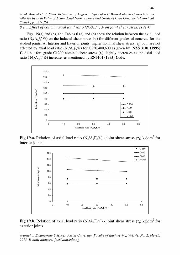
8.1.3. Effect of column axial load ratio (Nc/AcFc)% on joint shear stresses (τJ):
Figs. 19(a) and (b), and Tables 6 (a) and (b) show the relation between the axial load
ratio (Nc/Acc %) on the induced shear stress (j) for different grades of concrete for the
studied joints. At Interior and Exterior joints higher nominal shear stress (j) both are not
affected by axial load ratio (Nc/Acc%) for C250,400,600 as given by NZS 3101 (1995)
Code but for grade C1200 nominal shear stress (j) slightly decreases as the axial load
ratio ( Nc/Acc %) increases as mentioned by EN3101 (1995) Code.
Fig.19.a. Relation of axial load ratio (Nc/AcFc%) - joint shear stress (j) kg\cm2 for
interior joints
Fig.19.b. Relation of axial load ratio (Nc/AcFc%) - joint shear stress (j) kg\cm2 for
exterior joints
A. M. Ahmed et al, Static Behaviour of Different types of R.C Beam-Column Connections as
Affected by Both Value of Acting Axial Normal Force and Grade of Used Concrete (Theoretical
Study), pp. 321- 364
Journal of Engineering Sciences, Assiut University, Faculty of Engineering, Vol. 41, No. 2, March,
2013, E-mail address: [email protected]
347
0
5
10
15
20
25
0 200 400 600 800 1000 1200 1400
Interior Joint
Exterior Joint
Bo
nd
Str
en
gth
( b
) k
g/c
m²
Concrete compressive strength kg/cm² ( f'c)
0
2
4
6
8
10
0 200 400 600 800 1000 1200 1400
Interior Joint
Exterior Joint
Join
t S
hea
r S
tres
s \b
on
d S
tren
gth
( j \
b)
Concrete compressive strength kg/cm² ( f'c)
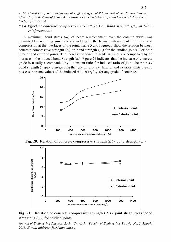
8.1.4. Effect of concrete compressive strength (fc') on bond strength (b) of beam
reinforcement:
A maximum bond stress (ub) of beam reinforcement over the column width was
estimated by assuming simultaneous yielding of the beam reinforcement in tension and
compression at the two faces of the joint. Table 5 and Figure20 show the relation between
concrete compressive strength (fc') on bond strength (b) for the studied joints. For both
interior and exterior joints. The increase of concrete grade is usually accompanied by an
increase in the induced bond Strength (b). Figure 21 indicates that the increase of concrete
grade is usually accompanied by a constant ratio for induced ratio of joint shear stress/
bond strength (j /b) disregarding the type of joint. i.e. Interior and exterior joints usually
possess the same values of the induced ratio of (j /b) for any grade of concrete.
Fig. 20. Relation of concrete compressive strength (fc') - bond strength (b)
Fig. 21. Relation of concrete compressive strength ( fc') - joint shear stress \bond
strength (j/ b) for studied joints
A. M. Ahmed et al, Static Behaviour of Different types of R.C Beam-Column Connections as
Affected by Both Value of Acting Axial Normal Force and Grade of Used Concrete (Theoretical
Study), pp. 321- 364
Journal of Engineering Sciences, Assiut University, Faculty of Engineering, Vol. 41, No. 2, March,
2013, E-mail address: [email protected]
348
0
40
80
120
160
200
240
0 200 400 600 800 1000 1200 1400
Interior Joint
Exterior Joint
Concrete compressive strength (fc`) kg/cm2
Ma
x.
pri
nci
ple
str
ess
(1)
kg
/cm
2
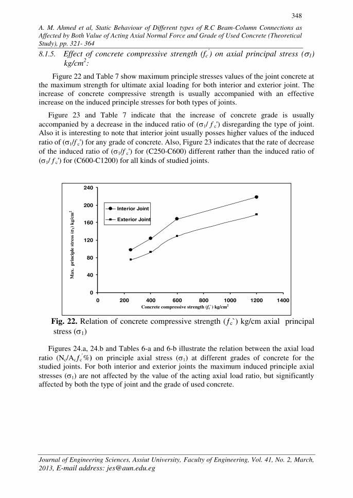
8.1.5. Effect of concrete compressive strength (fc') on axial principal stress (1)
kg/cm2:
Figure 22 and Table 7 show maximum principle stresses values of the joint concrete at
the maximum strength for ultimate axial loading for both interior and exterior joint. The
increase of concrete compressive strength is usually accompanied with an effective
increase on the induced principle stresses for both types of joints.
Figure 23 and Table 7 indicate that the increase of concrete grade is usually
accompanied by a decrease in the induced ratio of (1/ f c') disregarding the type of joint.
Also it is interesting to note that interior joint usually posses higher values of the induced
ratio of (1/f c') for any grade of concrete. Also, Figure 23 indicates that the rate of decrease
of the induced ratio of (1/f c') for (C250-C600) different rather than the induced ratio of
(1/ f c') for (C600-C1200) for all kinds of studied joints.
Fig. 22. Relation of concrete compressive strength (c`) kg/cm axial principal
stress (1)
Figures 24.a, 24.b and Tables 6-a and 6-b illustrate the relation between the axial load
ratio (Nc/Acc%) on principle axial stress (1) at different grades of concrete for the
studied joints. For both interior and exterior joints the maximum induced principle axial
stresses (1) are not affected by the value of the acting axial load ratio, but significantly
affected by both the type of joint and the grade of used concrete.

A. M. Ahmed et al, Static Behaviour of Different types of R.C Beam-Column Connections as
Affected by Both Value of Acting Axial Normal Force and Grade of Used Concrete (Theoretical
Study), pp. 321- 364
Journal of Engineering Sciences, Assiut University, Faculty of Engineering, Vol. 41, No. 2, March,
2013, E-mail address: [email protected]
349
0
0.1
0.2
0.3
0.4
0 200 400 600 800 1000 1200 1400
Interior Joint
Exterior Joint
Ma
x.
pri
nci
ple
str
ess\
com
pre
ssiv
e
Str
ength
((
1\
f c' )
Concrete compressive strength (fc`) kg/cm2
0
20
40
60
80
100
120
140
160
180
200
0 10 20 30 40 50 60
C 250
C400
C600
C1200
Axial load ratio (Nc/AcFc%)
Max.
Pri
nci
pa
l S
tres
s (
1)
kg
/cm
²
Fig. 23. Relation of concrete compressive strength (fc') - maximum principle
stress/concrete compressive strength (1/ fc') for studied joints
Fig. 24.a. Relation of axial load ratio (Nc/AcFc%) – maximum principal axial
stress (1) kg/cm2 for interior joints

A. M. Ahmed et al, Static Behaviour of Different types of R.C Beam-Column Connections as
Affected by Both Value of Acting Axial Normal Force and Grade of Used Concrete (Theoretical
Study), pp. 321- 364
Journal of Engineering Sciences, Assiut University, Faculty of Engineering, Vol. 41, No. 2, March,
2013, E-mail address: [email protected]
350
0
20
40
60
80
100
120
140
160
180
200
0 10 20 30 40 50 60
C 250
C400
C600
C1200
Axial load ratio (Nc/AcFc%)
Max
. P
rin
cip
al
Str
ess
(1)
kg/c
m²
Fig. 24.b. Relation of axial load ratio (Nc/AcFc%) – maximum principal axial
stress (1) kg/cm2 for exterior joints
Table 6
Effect of column axial load ratio (Nc/AcFc) on shear and axial stresses (τJ ,1): Table (6-a) Table (6-b)
A. M. Ahmed et al, Static Behaviour of Different types of R.C Beam-Column Connections as Affected by Both Value of Acting Axial Normal Force
and Grade of Used Concrete (Theoretical Study), pp. 321- 364
Journal of Engineering Sciences, Assiut University, Faculty of Engineering, Vol. 41, No. 2, March, 2013, E-mail address: [email protected]
351
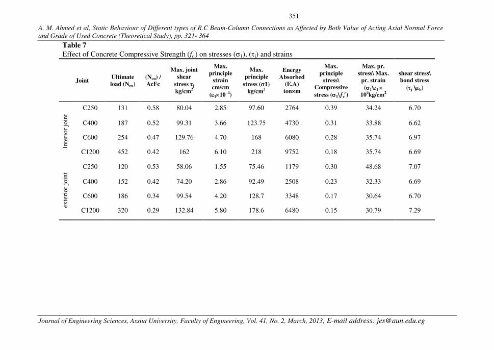
Table 7
Effect of Concrete Compressive Strength (fc') on stresses (1), (j) and strains
Joint Ultimate load (Ncu)
(Ncu) / AcFc
Max. joint shear
stress j
kg/cm2
Max. principle
strain cm/cm
(110–4)
Max. principle
stress (1)
kg/cm2
Energy Absorbed
(E.A) ton×m
Max. principle
stress\ Compressive
stress (1\c)
Max. pr. stress\ Max.
pr. strain
(1\1
104kg/cm2
shear stress\ bond stress
(j \b)
Inte
rio
r jo
int
C250 131 0.58 80.04 2.85 97.60 2764 0.39 34.24 6.70
C400 187 0.52 99.31 3.66 123.75 4730 0.31 33.88 6.62
C600 254 0.47 129.76 4.70 168 6080 0.28 35.74 6.97
C1200 452 0.42 162 6.10 218 9752 0.18 35.74 6.69
exte
rio
r jo
int
C250 120 0.53 58.06 1.55 75.46 1179 0.30 48.68 7.07
C400 152 0.42 74.20 2.86 92.49 2508 0.23 32.33 6.69
C600 186 0.34 99.54 4.20 128.7 3348 0.17 30.64 6.70
C1200 320 0.29 132.84 5.80 178.6 6480 0.15 30.79 7.29
A. M. Ahmed et al, Static Behaviour of Different types of R.C Beam-Column Connections as
Affected by Both Value of Acting Axial Normal Force and Grade of Used Concrete (Theoretical
Study), pp. 321- 364
Journal of Engineering Sciences, Assiut University, Faculty of Engineering, Vol. 41, No. 2, March,
2013, E-mail address: [email protected]
352
0
20
40
60
80
100
0 200 400 600 800 1000 1200 1400
Interior Joint
Exterior Joint
To
p a
xia
l d
isp
lace
men
t m
m (v
)
Concrete compressive strength (fc`) kg/cm2
0
1
2
3
4
5
6
7
0 200 400 600 800 1000 1200 1400
Interior Joint
Exterior Joint
Concrete compressive strength (fc) kg/cm2
Join
t p
rin
cipl
e st
rain
(1) 1
0-4
cm\c
m
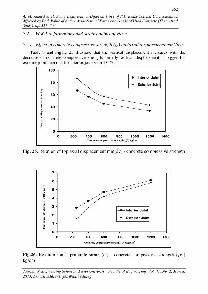
8.2. W.R.T deformations and strains points of view:
8.2.1. Effect of concrete compressive strength (fc') on (axial displacement mm(v):
Table 8 and Figure 25 illustrate that the vertical displacement increases with the
decrease of concrete compressive strength. Finally vertical displacement is bigger for
exterior joint than that for interior joint with 135%.
Fig. 25. Relation of top axial displacement mm(v) - concrete compressive strength
Fig.26. Relation joint principle strain ( 1) - concrete compressive strength (c`)
kg/cm
A. M. Ahmed et al, Static Behaviour of Different types of R.C Beam-Column Connections as
Affected by Both Value of Acting Axial Normal Force and Grade of Used Concrete (Theoretical
Study), pp. 321- 364
Journal of Engineering Sciences, Assiut University, Faculty of Engineering, Vol. 41, No. 2, March,
2013, E-mail address: [email protected]
353
0
20
40
60
80
100
0 200 400 600 800 1000 1200 1400
Interior Joint
Exterior Joint
Pr.
Str
ess
pr.
str
ain
(
1\
1)
kg/c
m2
Concrete compressive strength (fc) kg/cm2
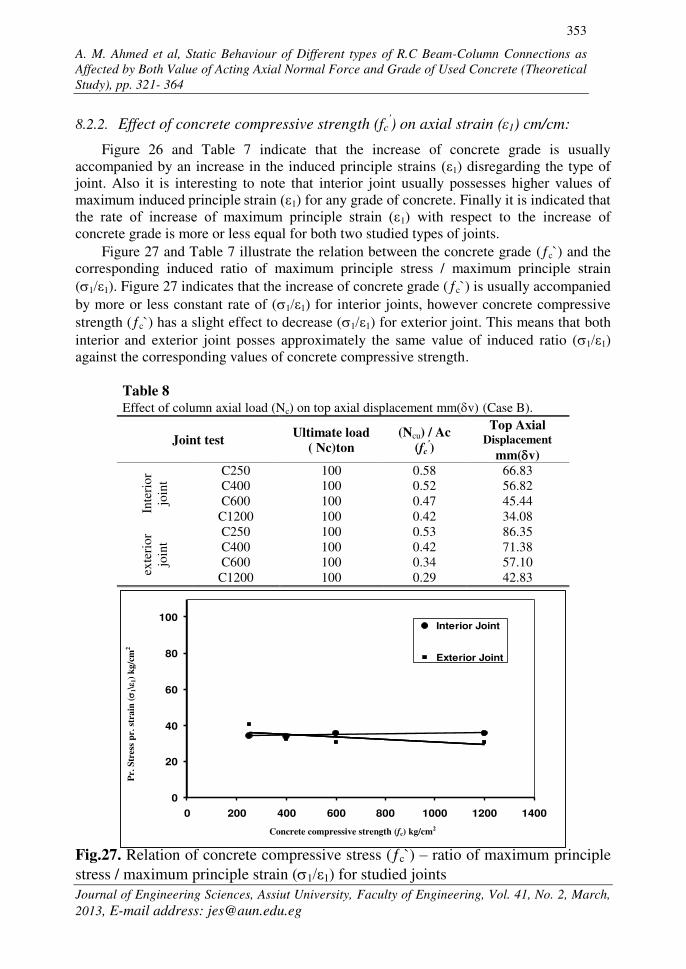
8.2.2. Effect of concrete compressive strength (fc') on axial strain (ε1) cm/cm:
Figure 26 and Table 7 indicate that the increase of concrete grade is usually
accompanied by an increase in the induced principle strains ( 1) disregarding the type of
joint. Also it is interesting to note that interior joint usually possesses higher values of
maximum induced principle strain ( 1) for any grade of concrete. Finally it is indicated that
the rate of increase of maximum principle strain ( 1) with respect to the increase of
concrete grade is more or less equal for both two studied types of joints.
Figure 27 and Table 7 illustrate the relation between the concrete grade (c`) and the
corresponding induced ratio of maximum principle stress / maximum principle strain
(1/ 1). Figure 27 indicates that the increase of concrete grade (c`) is usually accompanied
by more or less constant rate of (1/ 1) for interior joints, however concrete compressive
strength (c`) has a slight effect to decrease (1/ 1) for exterior joint. This means that both
interior and exterior joint posses approximately the same value of induced ratio (1/ 1)
against the corresponding values of concrete compressive strength.
Table 8 Effect of column axial load (Nc) on top axial displacement mm(v) (Case B).
Joint test Ultimate load ( Nc)ton
(Ncu) / Ac
(fc')
Top Axial Displacement
mm(v)
Inte
rio
r
join
t
C250 100 0.58 66.83
C400 100 0.52 56.82
C600 100 0.47 45.44
C1200 100 0.42 34.08
exte
rio
r
join
t
C250 100 0.53 86.35
C400 100 0.42 71.38
C600 100 0.34 57.10
C1200 100 0.29 42.83
Fig.27. Relation of concrete compressive stress (c`) – ratio of maximum principle
stress / maximum principle strain (1/ 1) for studied joints
A. M. Ahmed et al, Static Behaviour of Different types of R.C Beam-Column Connections as
Affected by Both Value of Acting Axial Normal Force and Grade of Used Concrete (Theoretical
Study), pp. 321- 364
Journal of Engineering Sciences, Assiut University, Faculty of Engineering, Vol. 41, No. 2, March,
2013, E-mail address: [email protected]
354
0
2000
4000
6000
8000
10000
0 200 400 600 800 1000 1200 1400
Interior Joint
Exterior Joint
En
ergy a
bso
rpti
on
(E.A
) t.
mm
Concrete compressive strength (fc) kg/cm2
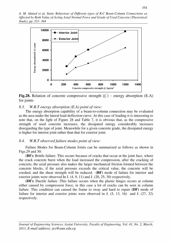
Fig.28. Relation of concrete compressive strength (fc
') – energy absorption (E.A)
for joints 8.3. W.R.T energy absorption (E.A) point of view:
The energy absorption capability of a beam-to-column connection may be evaluated
as the area under the lateral load-deflection curve. At this case of loading it is interesting to
note that, on the light of Figure 28 and Table 7, it is obvious that, as the compressive
strength of used concrete increases, the dissipated energy considerably increases
disregarding the type of joint. Meanwhile for a given concrete grade, the dissipated energy
is higher for interior joint rather than that for exterior joint.
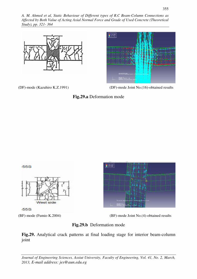
8.4. W.R.T observed failure modes point of view:
Failure Modes for Beam-Column Joints can be summarized as follows as shown in
Figs.29 and 30:
(BF): Brittle failure: This occurs because of cracks that occur at the joint face, where
the crack concrete burst when the load increased the compression, after the cracking of
concrete, the axial pressure also makes the larger mechanical friction formed between the
concrete blocks, if the axial pressure exceeds the critical value, the concrete will be
crushed, and the shear strength will be reduced. (BF) mode of failure for interior and
exterior joints were observed In J. (4, 9, 11) and J. (20, 25, 30) respectively.
(DF): Ductile failure :This failure occurs when the plastic hinges occurs at column
either caused by compression force, in this case a lot of cracks can be seen in column
failure. This condition can caused the frame to sway and hard to repair (DF) mode of
failure for interior and exterior joints were observed in J. (5, 13, 16) and J. (27, 32)
respectively.
A. M. Ahmed et al, Static Behaviour of Different types of R.C Beam-Column Connections as
Affected by Both Value of Acting Axial Normal Force and Grade of Used Concrete (Theoretical
Study), pp. 321- 364
Journal of Engineering Sciences, Assiut University, Faculty of Engineering, Vol. 41, No. 2, March,
2013, E-mail address: [email protected]
355
(DF)-mode (Kazuhiro K.Z.1991) (DF)-mode Joint No.(16)-obtained results
Fig.29.a Deformation mode
(BF)-mode (Fumio K.2004) (BF)-mode Joint No.(4)-obtained results
Fig.29.b Deformation mode
Fig.29. Analytical crack patterns at final loading stage for interior beam-column
joint

A. M. Ahmed et al, Static Behaviour of Different types of R.C Beam-Column Connections as
Affected by Both Value of Acting Axial Normal Force and Grade of Used Concrete (Theoretical
Study), pp. 321- 364
Journal of Engineering Sciences, Assiut University, Faculty of Engineering, Vol. 41, No. 2, March,
2013, E-mail address: [email protected]
356
(DF)-mode (Xiaoli Yang 2009) (DF)-mode Joint No.(32)-obtained results
Fig. 30.a Deformation mode
(BF)-mode (Hitoshi Sh. 2002) (BF)-mode Joint No.(20)-obtained results.
Fig. 30.b Deformation mode
Fig. 30. Analytical crack patterns at final loading stage for exterior beam-column
joint

A. M. Ahmed et al, Static Behaviour of Different types of R.C Beam-Column Connections as
Affected by Both Value of Acting Axial Normal Force and Grade of Used Concrete (Theoretical
Study), pp. 321- 364
Journal of Engineering Sciences, Assiut University, Faculty of Engineering, Vol. 41, No. 2, March,
2013, E-mail address: [email protected]
357
8.5. Conclusions and recommendations
The following conclusions are only valid for both interior and exterior joints where
corner (knee) joint did not have variable axial column load.
8.6. W.R.T loads and stresses point of view:
8.6.1. Column axial load:
The axial load ratio (Nc/Acc) generally decreases with the increase of concrete
compressive strength for the studied joints. Meanwhile, for a given grade of concrete,
for interior joint the axial load ratio is bigger than that for exterior one by 131%. This
reflects the fact that the interior joint is more effective in resisting axial load compared
with that for exterior joint.
8.6.2. Joint shear stresses (τJ):
The joint shear stress (τJ) for interior joint is higher than that for exterior with 125%.
This means that the interior joint is considerably safe than the exterior joint.
One of the findings of this study is that the joint strength coefficient, (γ) defined by
(=j /√fc'), changes with the variation of the column compressive axial load and
mainly depends on the type of joint where, from comparing the results joint shear
strength coefficient is given as average γ = 3.80 for exterior joint of column axial load,
and is given as average γ = 5.00 for interior joint of column axial load. It is declared that the (j/f
'c) mode strength decreases by increasing the grade of
concrete (f'c). Higher values were corresponding interior joints rather than that for
exterior joints.
8.6.3. Bond Stress (b) kg/cm2:
For both interior and exterior joints, the increase of concrete grade is usually
accompanied by an increase in the induced bond Strength (b).
tconsk
c
b tanf
u
'
where (k) is a constant depends on both used grade of concrete and type of joint as
well as case of loading.
The increase of concrete grade is usually accompanied by a constant ratio for induced
ratio of (j /b) disregarding the type of joint. Also, it is interesting to note that Interior
joint usually possess the same values of the induced ratio of (j /b) for any grade of
concrete.
Suggested values of (k) for calculating average bond capacity of RC joints at the
following Table.

A. M. Ahmed et al, Static Behaviour of Different types of R.C Beam-Column Connections as
Affected by Both Value of Acting Axial Normal Force and Grade of Used Concrete (Theoretical
Study), pp. 321- 364
Journal of Engineering Sciences, Assiut University, Faculty of Engineering, Vol. 41, No. 2, March,
2013, E-mail address: [email protected]
358
Type of Joint (k) values of (f'
c)
C250 and C400 C600 and C1200 Interior joint 0.72 0.74
Exterior joint 0.54 0.56
8.6.4. Axial principal stress (1) kg/cm2:
The increase of concrete compressive strength is effective to increase the principle
stresses and hence the increase of concrete grade is usually accompanied with a
decrease in the induced ratio of (1/f'c) disregarding the type of joint. Also, it is
interesting to note that interior joint usually posses higher values of the induced ratio
of (1/'c) for any grade of concrete.
8.7. W.R.T deformations and strains:
8.7.1. Axial displacement mm(v):
An axial displacement at different joint illustrated that vertical displacement increases
with the decrease of compressive strength. Finally vertical displacement is bigger at
exterior joint than of interior joint with 135%.
8.7.2. Axial strain (ε1) cm/cm:
Axial strain level is compared with the axial stress level for the various joints by
concrete compressive strength for plane beam-column joints, where an increase of
axial stress is usually followed by a corresponding increase of axial strain.
It is also observed that Interior joint usually possess a higher values of maximum
induced principle strains for any given grade of concrete.
It is indicated that the increase of concrete grade (c`) is usually accompanied by
constant rate of (1/ 1) for interior joints, however a slight effect to decrease (1/ 1) for
exterior joint. Finally the both interior and exterior joints have the same value of
induced ratio (1/ 1) against the corresponding values of concrete compressive
strength.
8.8. W.R.T energy absorption (E.A):
It is interesting to note that, for this case of loading as the compressive strength of
used concrete increases the dissipated energy considerably increases disregarding the
type of joint. Meanwhile for a given concrete grade the dissipated energy is higher for
interior joint rather than that for exterior joint.
8.9. W.R.T observed failure mode:
In this case of loading there are two types of modes of failure are observed namely:
BF mode Brittle failure: In joints No. J. (4, 9, 11) for interior joints and as joints
No. J. (20, 25, 30) for exterior joints.

A. M. Ahmed et al, Static Behaviour of Different types of R.C Beam-Column Connections as
Affected by Both Value of Acting Axial Normal Force and Grade of Used Concrete (Theoretical
Study), pp. 321- 364
Journal of Engineering Sciences, Assiut University, Faculty of Engineering, Vol. 41, No. 2, March,
2013, E-mail address: [email protected]
359
DF mode Ductile failure: In joints No. J. (5, 13, 16) for interior joints, and as joint
No. J. (27, 32) for exterior joints.
9. Recommendations The following topics can be recommended as subjects for future research studies.
1. To modify the joint failure at this case of loading an additional reinforcement can
significantly enhance the strength and toughness gains of the confined concrete.
The smaller tie spacing can also be provided at both upper and lower ends of the
column to prevent concrete bursting at that particular location during the test.
2. High strength concrete when it is used in columns connection, needs large
quantities of confining reinforcement to ensure ductile behavior, which can be
provided by high strength transverse reinforcement. The spacing recommendation
for confinement reinforcement from Comittee 352 appears to be valid for high-
strength joints so that it is found that the high-strength concrete grades achieved
higher levels of ductility, with better energy absorption and an increased initial
stiffness in comparison to identically detailed normal strength for internal, external
and knee specimens.
3. More experimental tests for RC beam-column connections are needed with
specific conditions such as using headed bars or fiber reinforced concrete will be
beneficial in the extension of understanding behavior of RC beam-column
connections.
4. The suggested joint shear behavior model was constructed based on standard
theoretical tests of RC beam-column connection subassemblies. Because the
boundary conditions of RC beam-column connections are often different in real
RC moment resisting frames (MRF), the effect of boundary conditions on joint
shear behavior could be further investigated
5. Nonlinearity due to concrete spalling and reinforcement buckling has not been
taken into account in the present analysis; hence it is needed further study.
6. More experimental tests are required to be taken into account the different section
geometry of columns beams. It is suggested that circular columns may be designed
in beam-column connections at the future investigation.
.

A. M. Ahmed et al, Static Behaviour of Different types of R.C Beam-Column Connections as
Affected by Both Value of Acting Axial Normal Force and Grade of Used Concrete (Theoretical
Study), pp. 321- 364
Journal of Engineering Sciences, Assiut University, Faculty of Engineering, Vol. 41, No. 2, March,
2013, E-mail address: [email protected]
360
Nomenclature
Ab Gross area of cross section of beam.
Ag, Ac Gross area of cross section of column.
Acs Area of the column reinforcement.
Aj Horizontal sectional area of joint core.
As1, As2 Top and bottom reinforcements of beam respectively.
Ast The area of longitudinal reinforcement.
at Total area of tensile reinforcement.
ag Total area of longitudinal reinforcement.
aw
Total area of web reinforcement placed between top and
bottom beam bars.
dc, db Effective depth of beam, effective depth of column .
E.A Energy Absorption.
Ec The concrete static modulus.
Es The steel elastic modulus.
E0 The plastic strain.
ƒ′c Compressive cylinder strength of concrete.
ƒcu The cube strength.
ƒt Concrete tensile strength.
ƒy Yield strength of steel reinforcement.
H The total height of the columns above and below the joint.
hc, hcol Depth of column.
hj Effective depth of joint.
Lb,L Length of the beam right and left the joint.
Lc The heights of the columns above and below the joint.
Nc Axial column loads.
Ncu The ultimate axial column load obtained.
Ncc The cracking axial column load obtained.
Vc Column shear force.
γ The nominal strength coefficient.
v Axial top displacement.
1 principal axial strains.
1 principal axial stress.
τJ Joint shear stress.
ρw Joint shear reinforcement.
A. M. Ahmed et al, Static Behaviour of Different types of R.C Beam-Column Connections as
Affected by Both Value of Acting Axial Normal Force and Grade of Used Concrete (Theoretical
Study), pp. 321- 364
Journal of Engineering Sciences, Assiut University, Faculty of Engineering, Vol. 41, No. 2, March,
2013, E-mail address: [email protected]
361
References
[1] ABQUS, ABAQUS Theory Manual, (v6.7-1) (2002), Training Manual, (v6.5-1) (2004), User Manual, (v6.5-1) (2000).
[2] ACI 318M-02 (2002): “Building code requirements for structural concrete and commentary”, Reported by ACI Committee 318, American Concrete Institute, Farmington Hills, Michigan.
[3] ACI-ASCE Committee 352 (1995): “Recommendations for Design of Beam-
Column Joints in εonolithic Reinforced Concrete Structures” (AC1 352R-95),
American Concrete Institute, Detroit, Michigan, 1995. [4] British Standards Institution, BS8110 (1985): “Structural use of concrete”, Part
1 Code of practice for design and construction, London, U.K.
[5] Beres, A., White, A.N., and Gergely, P. (1992): Seismic behavior of RC frame
structures with on ductile details: Part I-Summary of experimental findings of full
scale beam-column joint tests, Report NCEER-92-0024, NCEER, SUNY Buffalo,
NY.
[6] Bing Li, Yiming Wu, and Tso-Chien Pan (2003): “Seismic Behavior of Non seismically Detailed interior Beam-Wide Column joints-Part2: Theoretical
Comparisons and Analytical Studies” ACI Structural journal, V.100, No.1,
January-February. 2003. PP.56-65.
[7] Building Seismic Safety Council (1997): FEMA 273: NEHRP Guidelines for the
Seismic\Rehabilitation of Buildings. Federal Emergency Management Agency,
Washington, DC.
[8] Chris P. Pantelides, Jon Hansen, Justin Nadauld and Lawrence D. Reaveley (2002): “Assessment of Reinforced Concrete Building Exterior Joints with
Substandard Details” Pacific Earthquake Engineering Research Center College of
Engineering University of California, Berkeley May 2002. [9] EN 1998-1:2003, “General rules-specific rules for various materials and
elements”, Euro code 8: Design Provisions for Earthquake Resistant Structures. [10]Filica Thin Ying Chik (2007): “Influence of Different Concrete Strength on The
Behavior of Interior Reinforced Concrete Beam-Column Joint” Degree of master of civil Engineering University of Technology Malaysia, November 2007.
[11] Hakuto, S., Park, R. and Tanaka, H. (2000): “Seismic load tests on interior and exterior beam-column joints with substandard reinforcing details”, ACI Structure. J., 97(1), PP.11-25.
[12] J. Lee and G. L. Fenves (1998): “Plastic-Damaged model for cycling loading of
concrete structures”, 124(8), Journal of Engineering Mechanics 21-40 Feb.2005.
[13] Kupfer, H., Hilsdorf, H.K., Rüsch, H. (2011): Behavior of Concrete under
Biaxial Stress, Journal ACI, Proc. V.66, No.8, Aug., pp.656-666.
[14] Kurose, Y. (1987): “Recent studies on reinforced concrete beam column joints in
Japan” PεFSEδ Report No. 87-8 Department of Civil Engineering, University
of Texas at Austin, Austin, TX.
[15] Kumar, S.R.S. B.V. and G.S.B., (2002): “Hysteretic behavior of lightly reinforced–concrete exterior beam–to–column joint sub-assemblages”. J. Struc. Eng. SERC, 29 (1):31-37.

A. M. Ahmed et al, Static Behaviour of Different types of R.C Beam-Column Connections as
Affected by Both Value of Acting Axial Normal Force and Grade of Used Concrete (Theoretical
Study), pp. 321- 364
Journal of Engineering Sciences, Assiut University, Faculty of Engineering, Vol. 41, No. 2, March,
2013, E-mail address: [email protected]
362
[16] NZS 3101 (1995): “The design of concrete structures”, Concrete Structures
Standard, Part 1: Code of Practice, Part 2: Commentary, Standards New Zealand,
Wellington, New Zealand, 256 pp & 264 pp.
[17] Park R. and Paulay T. (1975): Reinforced Concrete Structures, John Wiley &
Sons, New York, USA, 769 pp.
[18] Paul S. Baglin and Richard H. Scott (2000): “Finite Element εodeling of Reinforced concrete Beam- Column Connections." ACI Structural journal, V.97,
No.6, November-December. 2000 PP. 886-894
[19] Sam Lee (2008): “Nonlinear Dynamic Earthquake Analysis of Skyscrapers” Guangzhou Scientific Computing Consultants Co. Ltd, 507/140 Dong fang Xi
Rd, Guangzhou 510170, 7 China, [email protected] CTBUH 8th World
Congress, Dubai, 3-5 March 2008
[20] S. R. Uma and Sudhir K. Jain (2006): "Seismic design of beam-column joints in
RC moment resisting frames – Review of codes "Structural Engineering and
Mechanics, Vol. 23, No. 5 (2006) 579-597 579N Department of Civil
Engineering, Indian Institute of Technology, University of Canterbury, New
Zealand.
[21] Xiaoli Yang, Guoliang Bai and Hongxing Li (2009): “Study on Design Method
of SRC Abnormal Exterior Joint of Large-scale Thermal Power Plant Frame-bent
Structure”, School of Civil Engineering, Xi’an University of Architecture and
Technology China Vol. 3, No. 9 Modern Applied Science Sep. 2009.

A. M. Ahmed et al, Static Behaviour of Different types of R.C Beam-Column Connections as
Affected by Both Value of Acting Axial Normal Force and Grade of Used Concrete (Theoretical
Study), pp. 321- 364
Journal of Engineering Sciences, Assiut University, Faculty of Engineering, Vol. 41, No. 2, March,
2013, E-mail address: [email protected]
363
" السلو ااستاتيكي لانوا المختلف من الوصا الخرساني المسلح بين الكمرر االممروت تحر و الراسي المح وري االرتب الخرساني المستخدم "تأثير كا من ال
) ري ) تراس ن
ملخص:بعيحة ايم اطيحٳت ات يحك احتديما ألتم في ذي ا احث يم ديا ة اظيي لمجيي حدندا يي ديحة اثيم يي يي ا
حةا ظيي ABAQUS\CAE 6.7 شيحي إل دية احةالي يي لاحرح ة يي بحظييرةان بم يحاي تدث ياتم حيي ي يا األبحسياك ااظيحت ت حه ه احاص ت ت تأ م احثا احماظ ي احد ا جي احديغ م اي احثيا احعاااا احدؤ م ي اح
احعمض ي حبيي حمتب احرمظح ي احديغ م حياص . لةحك ام ل ك تأ مذم ي اةهحةا احثص لااةهحةا اططثيي ات يحك لاحيشت احطحتني فيام ل ك ق م ا دحك احيشمجخ لأق دا ة لاا فعحا احد ا جي
دة بحاضحفي اح تد ي احطحقي احددي ي ل ححي لٳماز اا ه ح .ألاحتدما بح ححي حدطحٳت ات حك احتديما بحا ديةه 23لحة اظي ظياك ذ ه احاص لاثح ي احطيحيي احطلمجي تم ة اظي
احرمظح ي احةالي ي لاحرح ة ي م تم تثث ت احث ح ح احيحح ي:
Ac (bc×dc) mmاسيح ي اثطي احعدياة mm (250×300) mm, Ab (bb×db)حتديم اسيح ي اثطي ا
(300×300mm) اسيح ي اططثيي اات يحك احتديم بيححعداة (H×L)m (2.0×3.0) m, Aj اسيح ي ةجية لاسيييييح ي ةجييييية تسيييييي م احتديييييما ييييييا ل ظيييييفي Acs (Ф 16 12) تسيييييي م احعدييييياة
(16 ( 4 Ф As1, As2 ل سيثي تازجي احتح يح Ф6 \ 08 (ايم ( pw لتي حك ححيي احطهحجيح احطمف يي حدططثييحند احع طح تح ت حبيي اي اظييرةان 120mm =tsلاا دة ا ثا ظدك احث ٳي اات حك احتدما ،
of ,('ƒc)احدرييفيي. يم تييمالق اثحلايي احليغر حيرمظيح ي احدسيي ي بي م تب ايغ م حيرمظح ي احدسيي ي250–400–600–1200 kg/cm
2جييان لأجلييحب تييب ةجيية احيسييي م احددتييم 30حيدتعثييح احث حظيي ي بعيية ,
–2400–2800–3600 (ƒy) اظييرةاا في أ ديحك احرمظيح ي احدسيي ي ب يم جييمالق اةهيحة احرليا بي م 4000 kg/cm
2 ي احيااح حدطحٳت اات حك احرمظح ي احدرييفي احةالي يي لاحرح ة يي. تيم احي ديا طية قديي يم (Vc)أفث يي حبييي ا ي ابي بثيا قيص( %Nc\AcFcعداة ب دا أظ ا ا حيعداة بطسيثي ايغ يم )اح
ل (1)تث م ت ام اازا يح احمأظي ي احديغ يم احطحتنيي ايم احي د يا لأق ي اةهيحةا لا فعيحا ا ا جيي ( ه يح احدياقعيي لةحيك ل ححيي اا (E.A)اةهيحةا احثيص ، بحإلضيحفي حي احطحقيي احددي يي (τJ) لأق ي (1
اظييرةان ء يم ٳمجيت ABAQUS\CAE version 6.7 بحظييرةان بم يحاي حيي ي يا ااظييحت ت احغ يم لطي م تم ة اظي ظدح مةيي ايطا يي يي ظيياك اططثيي (Sam Lee 2008) داة تم احيأتة اط بااظطي
حند احه حتا احرمظح ي احدسي ي لاليثح اات حك ب م )األ دة لاحتدما ( احرمظح ي لاحي ي ا احدمن احيةن .ABAQUSاحسعي احث ي ا دحك احزازك بححي ي ا احغ م لط احةجطحا ت حثم حاي
ااةهيحةا لاحدثحلايح حدطيحٳت تم مض لت ي ا حيطيحيي احطلمجي احدي ا ي هح ام لةهيح احطليم احيحح يي:يشيت لاا فعي احدرييفيي حدطيحٳت ات يحا احتديما اح; ات حك احتديما بحأل دية احةالي يي لاحرح ة يي
بحا ديييييييييييييييييييييية احةالي ييييييييييييييييييييييي ل احرح ة ييييييييييييييييييييييي احطحقييييييييييييييييييييييي احتي ييييييييييييييييييييييي احددي ييييييييييييييييييييييي ( (E.A( حدطحٳت ات حك احتدما ل اا دة احةالي ي احرح ة ي.اح دا اح ة احد ا(Ncu ل دا احيشمجخ
(Ncc) ; ي )ل ال ماب حا اا ه ح احدرييفي حياص احرمظح . (DF). (BF
: التوصياحزجحة قة لظعي ت دا احاصي لحيطياجم ا ه يح اطيحٳت ات يحك احتديما بحأل دية جييزن اضيحفي ةجية -1
حي زجم احرمظح ي لتثي ا احدسحفي ب م اح ةجة حيي زجم ي لةه احعداة احعيا لاحسفي حدط احرمظح ي ايم احيثش م ل ك احي د ا احماظ بحأل دة .
اظيرةان لمظح ي حح ي احدثحلاي ف األ دة ف اطحٳت ات حك ت ييح احي ةجية ت يزجم حييأتية ايم حةل يي -3احسياك احي جدتيم ان جيطيا بحظييرةان ةجية يح ا يحح احدثحلايي اي اما يح احدسيحفي حي ةجية احي يزجم
A. M. Ahmed et al, Static Behaviour of Different types of R.C Beam-Column Connections as
Affected by Both Value of Acting Axial Normal Force and Grade of Used Concrete (Theoretical
Study), pp. 321- 364
Journal of Engineering Sciences, Assiut University, Faculty of Engineering, Vol. 41, No. 2, March,
2013, E-mail address: [email protected]
364
ح يي بحظييرةان اثحلايي حةجيي حدطيحٳت ا طحء حةل ي حح ي لزجحة ف احطحقي احددي ي ا ايح ي حح ي بححدث اات حك احةالي ي لاحرح ة ي لاحمتط ي.
بعييا احة اظييح اطيابييي حدطييحٳت ت ييحك احرمظييح ي احدسييي ي احتدييما بحأل ديية بحظيييرةان ةجيية اضييحف –2 ةالي أل لمظح ي اسي ي ةا اح حف حة اظي ظياك اطحٳت احاص احرمظح ي احدسي ي.
حث يي جعيديية ييي احة اظييح احطلمجييي احث حظيي ي حدطييحٳت األت ييحك احتدييما بحأل ديية ظييياك احاصيي ا -4احرمظح ي احدسي ي بسثب احطهحجح احطمف ي حدطحٳت اات حك ف نيب ة اظيي تيأ م تغ يم احطهحجيح احطمف يي
حدطحٳت اات حك. يم ان ةحيك ر يم ايألاة في األل ف اا يثح احي ي ا احغ م لط طة تثش م احرمظح ي ل يةل ا طيحء -5
اح سحبح احرحصي بححث م. بعييا احة اظييح األلييما ايي االيي فيي اا يثييح الييي ف ةييتا قطح ييح اا ديية طيية احاصيي ا -6
حيثطح ح احةايمجي حأ دة جنب ة اظيهح.