3.2 main circuit wiring - galco industrial electronics gauges and tightening torque select the...
TRANSCRIPT

3.2 Main Circuit WiringThis section describes the functions, specifications, and procedures required to safely andproperly wire the main circuit of the drive.NOTICE: Do not solder the ends of wire connections to the drive. Soldered wiring connections can loosenover time. Improper wiring practices could result in drive malfunction due to loose terminal connections.
u Main Circuit Terminal FunctionsTable 3.1 Main Circuit Terminal Functions
Terminal Type Function ReferenceR/L1
Main circuit powersupply input
Connects line power to the drive.Drives with single-phase 200 V input power use terminals R/L1 andS/L2 only (T/L3 must not be used).
–S/L2T/L3U/T1
Drive output Connects to the motor. 36V/T2W/T3
B1Braking resistor Available for connecting a braking resistor or the braking resistor
unit option. –B2+1 DC reactor
connectionThese terminals are shorted at shipment. Remove the shorting barbetween +1 and +2 when connecting a DC reactor to this terminal. –
+2+1 DC power supply
input For connecting a DC power supply. ––
(2 terminals) GroundGrounding TerminalFor 200 V class: 100 Ω or lessFor 400 V class: 10 Ω or less
36
u Wire Gauges and Tightening TorqueSelect the appropriate wires and crimp terminals from Table 3.2 through Table 3.4.
Note: 1. Wire gauge recommendations based on drive continuous current ratings using 75 °C 600 Vac vinyl-sheathed wire assuming ambient temperature within 30 °C and wiring distance less than 100 m.
2. Terminals +1, +2, –, B1 and B2 are for connecting optional devices such as a DC reactor or brakingresistor. Do not connect other non-specified devices to these terminals.
• Consider the amount of voltage drop when selecting wire gauges. Increase the wire gaugewhen the voltage drop is greater than 2% of motor rated voltage. Ensure the wire gauge issuitable for the terminal block. Use the following formula to calculate the amount of voltagedrop:
• Line drop voltage (V) = 3 x wire resistance (Ω/km) x wire length (m) x current (A) x10-3
• Refer to instruction manual TOBPC72060000 for braking unit or braking resistor unit wiregauges.
• Refer to UL Standards Compliance on page 156 for information on UL compliance.
3.2 Main Circuit Wiring
YASKAWA ELECTRIC TOEP C710606 14C YASKAWA AC Drive – V1000 Quick Start Guide 33
3
Elec
tric
al In
stal
latio
n

n Single-Phase 200 V ClassTable 3.2 Wire Gauge and Torque Specifications
ModelCIMR-VoBA
Terminal ScrewSize
TighteningTorque
N•m (lb.in.)
ApplicableGauge
mm2 (AWG)
RecommendedGauge
mm2 (AWG)000100020003
R/L1, S/L2, U/T1, V/T2, W/T3,–, +1, +2, B1, B2, M3.5 0.8 to 1.0
(7.1 to 8.9)0.75 to 2.0(18 to 14)
2(14)
0006 R/L1, S/L2, U/T1, V/T2, W/T3,–, +1, +2, B1, B2, M4 1.2 to 1.5
(10.6 to 13.3)2.0 to 5.5(14 to 10)
2(14)
0010
R/L1, S/L2, U/T1, V/T2, W/T3, M4 1.2 to 1.5(10.6 to 13.3)
2.0 to 5.5(14 to 10)
3.5(12)
–, +1, +2, B1, B2 M4 1.2 to 1.5(10.6 to 13.3)
2.0 to 5.5(14 to 10)
5.5(10)
0012 R/L1, S/L2, U/T1, V/T2, W/T3,–, +1, +2, B1, B2, M4 1.2 to 1.5
(10.6 to 13.3)2.0 to 5.5(14 to 10)
5.5(10)
0018 R/L1, S/L2, U/T1, V/T2, W/T3,–, +1, +2, B1, B2, M5 2 to 2.5
(17.7 to 22.1)3.5 to 8(12 to 8)
8(8)
n Three-Phase 200 V ClassTable 3.3 Wire Gauge and Torque Specifications
ModelCIMR-Vo2A
Terminal ScrewSize
TighteningTorque
N•m (lb.in.)
ApplicableGauge
mm2 (AWG)
RecommendedGauge
mm2 (AWG)0001000200040006
R/L1, S/L2, T/L3, U/T1, V/T2, W/T3, –, +1, +2, B1, B2, M3.5 0.8 to 1.0
(7.1 to 8.9)0.75 to 2.0(18 to 14)
2(14)
0010
R/L1, S/L2, T/L3, U/T1, V/T2, W/T3, –, +1, +2, B1, B2 M4 1.2 to 1.5
(10.6 to 13.3)2.0 to 5.5(14 to 10)
2(14)
M4 1.2 to 1.5(10.6 to 13.3)
2.0 to 5.5(14 to 10)
3.5(12)
0012 R/L1, S/L2, T/L3, U/T1, V/T2, W/T3, –, +1, +2, B1, B2, M4 1.2 to 1.5
(10.6 to 13.3)2.0 to 5.5(14 to 10)
3.5(12)
0020 R/L1, S/L2, T/L3, U/T1, V/T2, W/T3, –, +1, +2, B1, B2, M4 1.2 to 1.5
(10.6 to 13.3)2.0 to 5.5(14 to 10)
5.5(10)
0030
R/L1, S/L2, T/L3, U/T1, V/T2, W/T3, -, +1, +2 M4 1.2 to 1.5
(10.6 to 13.3)5.5 to 14(10 to 6)
8(8)
B1, B2 M4 1.2 to 1.5(10.6 to 13.3)
2.0 to 5.5(14 to 10)
5.5(10)
M5 2 to 2.5(17.7 to 22.1)
5.5 to 14(10 to 6)
8(8)
0040
R/L1, S/L2, T/L3, U/T1, V/T2, W/T3, -, +1, +2 M4 1.2 to 1.5
(10.6 to 13.3)5.5 to 14(10 to 6)
14(6)
B1, B2 M4 1.2 to 1.5(10.6 to 13.3)
2.0 to 5.5(14 to 10)
5.5(10)
M5 2 to 2.5(17.7 to 22.1)
5.5 to 14(10 to 6)
8(8)
3.2 Main Circuit Wiring
34 YASKAWA ELECTRIC TOEP C710606 14C YASKAWA AC Drive – V1000 Quick Start Guide

ModelCIMR-Vo2A
Terminal ScrewSize
TighteningTorque
N•m (lb.in.)
ApplicableGauge
mm2 (AWG)
RecommendedGauge
mm2 (AWG)
0056
R/L1, S/L2, T/L3, U/T1, V/T2, W/T3, -, +1, +2 M6 4 to 6
(35.4 to 53.1)14 to 22(6 to 4)
22(4)
B1, B2 M5 2 to 2.5(17.7 to 22.1)
5.5 to 8(10 to 8)
8(8)
M6 4 to 6(35.4 to 53.1)
14 to 22(6 to 4)
22(4)
0069
R/L1, S/L2, T/L3, U/T1, V/T2, W/T3, -, +1, +2 M8 9 to 11
(79.7 to 11.0)8 to 38(8 to 2)
38(2)
B1, B2 M5 2 to 2.5(17.7 to 22.1)
8 to 14(8 to 6)
14(6)
M6 4 to 6(35.4 to 53.1)
8 to 22(8 to 4)
22(4)
n Three-Phase 400 V ClassTable 3.4 Wire Gauge and Torque Specifications
ModelCIMR-Vo4A
Terminal ScrewSize
TighteningTorque
N•m (lb.in.)
ApplicableGauge
mm2 (AWG)
RecommendedGauge
mm2 (AWG)00010002000400050007
R/L1, S/L2, T/L3, U/T1, V/T2, W/T3, –, +1, +2, B1, B2, M4 1.2 to 1.5
(10.6 to 13.3)2.0 to 5.5(14 to 10)
2(14)
0009
R/L1, S/L2, T/L3, U/T1, V/T2, W/T3, –, +1, +2, B1, B2 M4 1.2 to 1.5
(10.6 to 13.3)2.0 to 5.5(14 to 10)
2(14)
M4 1.2 to 1.5(10.6 to 13.3)
2.0 to 5.5(14 to 10)
3.5(12)
0011
R/L1, S/L2, T/L3, U/T1, V/T2, W/T3, –, +1, +2, B1, B2 M4 1.2 to 1.5
(10.6 to 13.3)2.0 to 5.5(14 to 10)
2(14)
M4 1.2 to 1.5(10.6 to 13.3)
2.0 to 5.5(14 to 10)
3.5(12)
0018
R/L1, S/L2, T/L3, U/T1, V/T2, W/T3, -, +1, +2, B1, B2 M4 1.2 to 1.5
(10.6 to 13.3)2.0 to 5.5(14 to 10)
5.5(10)
M5 2 to 2.5(17.7 to 22.1)
5.5 to 14(10 to 6)
5.5(10)
0023
R/L1, S/L2, T/L3, U/T1, V/T2, W/T3, -, +1, +2 M4 1.2 to 1.5
(10.6 to 13.3)5.5 to 14(10 to 6)
8(8)
B1, B2 M4 1.2 to 1.5(10.6 to 13.3)
2.0 to 5.5(14 to 10)
5.5(10)
M5 2 to 2.5(17.7 to 22.1)
5.5 to 14(10 to 6)
5.5(10)
0031
R/L1, S/L2, T/L3, U/T1, V/T2, W/T3, -, +1, +2 M5 2 to 2.5
(17.7 to 22.1)5.5 to 14(10 to 6)
8(8)
B1, B2 M5 2 to 2.5(17.7 to 22.1)
5.5 to 8(10 to 8)
8(8)
M6 4 to 6(35.4 to 53.1)
5.5 to 14(10 to 6)
8(8)
3.2 Main Circuit Wiring
YASKAWA ELECTRIC TOEP C710606 14C YASKAWA AC Drive – V1000 Quick Start Guide 35
3
Elec
tric
al In
stal
latio
n

ModelCIMR-Vo4A
Terminal ScrewSize
TighteningTorque
N•m (lb.in.)
ApplicableGauge
mm2 (AWG)
RecommendedGauge
mm2 (AWG)
0038
R/L1, S/L2, T/L3, U/T1, V/T2, W/T3, -, +1, +2 M5 2 to 2.5
(17.7 to 22.1)5.5 to 14(10 to 6)
14(6)
B1, B2 M5 2 to 2.5(17.7 to 22.1)
5.5 to 8(10 to 8)
8(8)
M6 4 to 6(35.4 to 53.1)
5.5 to 14(10 to 6)
8(8)
u Main Circuit Terminal Power Supply and Motor WiringThis section outlines the various steps, precautions, and checkpoints for wiring the main circuitterminals and motor terminals.NOTICE: When connecting the motor to the drive output terminals U/T1, V/T2, and W/T3, the phase orderfor the drive and motor should match. Failure to comply with proper wiring practices may cause the motor torun in reverse if the phase order is backward.
NOTICE: Do not connect phase-advancing capacitors or LC/RC noise filters to the output circuits. Improperapplication of noise filters could result in damage to the drive.
NOTICE: Do not connect the AC power line to the output motor terminals of the drive. Failure to comply couldresult in death or serious injury by fire as a result of drive damage from line voltage application to outputterminals.
n Cable Length Between Drive and MotorWhen the cable length between the drive and the motor is too long (especially at low frequencyoutput), note that the cable voltage drop may cause reduced motor torque. Drive output currentwill increase as the leakage current from the cable increases. An increase in leakage currentmay trigger an overcurrent situation and weaken the accuracy of the current detection.Adjust the drive carrier frequency according to the following table. If the motor wiring distanceexceeds 100 m because of the system configuration, reduce the ground currents.Refer to Table 3.5 to set the carrier frequency to an appropriate level.
Table 3.5 Cable Length Between Drive and MotorCable Length 50 m or less 100 m or less Greater than 100 m
Carrier Frequency 15 kHz or less 5 kHz or less 2 kHz or less
Note: When setting carrier frequency, calculate the cable length as the total distance of wiring to all connectedmotors when running multiple motors from a single drive.
n Ground WiringFollow the precautions to wire the ground for one drive or a series of drives.WARNING! Electrical Shock Hazard. Always use a ground wire that complies with technical standards onelectrical equipment and minimize the length of the ground wire. Improper equipment grounding may causedangerous electrical potentials on equipment chassis, which could result in death or serious injury.
3.2 Main Circuit Wiring
36 YASKAWA ELECTRIC TOEP C710606 14C YASKAWA AC Drive – V1000 Quick Start Guide

WARNING! Electrical Shock Hazard. Be sure to ground the drive ground terminal. (200 V Class: Ground to100 Ω or less, 400 V Class: Ground to 10 Ω or less). Improper equipment grounding could result in death orserious injury by contacting ungrounded electrical equipment.
NOTICE: Do not share the ground wire with other devices such as welding machines or large-current electricalequipment. Improper equipment grounding could result in drive or equipment malfunction due to electricalinterference.
NOTICE: When using more than one drive, ground multiple drives according to instructions. Improperequipment grounding could result in abnormal operation of drive or equipment.
Refer to Figure 3.3 when using multiple drives. Do not loop the ground wire.A BA
A – Correct B – Incorrect
Figure 3.3 Multiple Drive Wiring
n Wiring the Main Circuit TerminalWARNING! Electrical Shock Hazard. Shut off the power supply to the drive before wiring the main circuitterminals. Failure to comply may result in death or serious injury.
Note: A cover placed over the DC Bus and braking circuit terminals prior to shipment helps prevent miswiring.Cut away covers as needed for terminals with a needle-nose pliers.
A
A – Protective Cover to Prevent Miswiring
Note: The ground terminal screw on IP20/NEMA Type 1 holds the protective cover in place.
3.2 Main Circuit Wiring
YASKAWA ELECTRIC TOEP C710606 14C YASKAWA AC Drive – V1000 Quick Start Guide 37
3
Elec
tric
al In
stal
latio
n

3.3 Control Circuit Wiring
u Control Circuit Terminal Block FunctionsDrive parameters determine which functions apply to the multi-function digital inputs (S1 toS7), multi-function digital outputs (MA, MB), multi-function pulse inputs and outputs (RP,MP) and multi-function photocoupler outputs (P1, P2). The default is called out next to eachterminal in Figure 3.1.WARNING! Sudden Movement Hazard. Always check the operation and wiring of control circuits after beingwired. Operating a drive with untested control circuits could result in death or serious injury.
WARNING! Confirm the drive I/O signals and external sequence before starting test run. Setting parameterA1-06 may change the I/O terminal function automatically from the factory setting. Refer to Application Selection on page 65. Failure to comply may result in death or serious injury.
n Input TerminalsTable 3.6 Control Circuit Input Terminals
Type No. Terminal Name (Function) Function (Signal Level) Default Setting
Multi-FunctionDigitalInputs
S1 Multi-function input 1 (Closed: Forwardrun, Open: Stop)
Photocoupler24 Vdc, 8 mANote: Drive preset to sinking mode. When usingsource mode, set DIP switch S3 to allow for a 24 Vdc(±10%) external power supply. Refer to Sinking/Sourcing Mode Switch on page 44.
S2 Multi-function input 2 (Closed: Reverse run,Open: Stop)
S3 Multi-function input 3 (External fault (N.O.)S4 Multi-function input 4 (Fault reset)
S5 Multi-function input 5 (Multi-step speedreference 1)
S6 Multi-function input 6 (Multi-step speedreference 2)
S7 Multi-function input 7 (Jog reference)
SC Multi-function input common (Controlcommon) Sequence common
SafeDisableInput
HC Power supply for safe disable input +24 Vdc (max 10 mA allowed)
H1 Safe disable input
Open: Output disabledClosed: Normal operationNote: Disconnect wire jumper between HC and H1when using the safe disable input. The wire lengthshould not exceed 30 m.
3.3 Control Circuit Wiring
38 YASKAWA ELECTRIC TOEP C710606 14C YASKAWA AC Drive – V1000 Quick Start Guide

Type No. Terminal Name (Function) Function (Signal Level) Default Setting
MainFrequencyReferenceInput
RP Multi-function pulse train input (frequencyreference)
Response frequency: 0.5 to 32 kHz(Duty Cycle: 30 to 70%)(High level voltage: 3.5 to 13.2 Vdc)(Low level voltage: 0.0 to 0.8 Vdc)(input impedance: 3 kΩ)
+V Analog input power supply +10.5 Vdc (max allowable current 20 mA)
A1 Multi-function analog input 1 (frequencyreference) Input voltage 0 to +10 Vdc (20 kΩ) resolution 1/1000
A2 Multi-function analog input 2 (frequencyreference)
Input voltage or input current (Selected by DIP switchS1 and H3-01) 0 to +10 Vdc (20 kΩ),Resolution: 1/10004 to 20 mA (250 Ω) or 0 to 20 mA (250 Ω),Resolution: 1/500
AC Frequency reference common 0 Vdc
n Output TerminalsTable 3.7 Control Circuit Output Terminals
Type No. Terminal Name (Function) Function (Signal Level) Default Setting
Multi-FunctionDigital Output
MA N.O. (fault) Digital output30 Vdc, 10 mA to 1 A; 250 Vac, 10 mA to 1 AMinimum load: 5 Vdc, 10 mA (reference value)
MB N.C. output (fault)MC Digital output common
Multi-FunctionPhotocoupler Output
P1 Photocoupler output 1 (During run)Photocoupler output 48 Vdc, 2 to 50 mAP2 Photocoupler output 2 (Frequency agree)
PC Photocoupler output common
Monitor OutputMP Pulse train output (Output frequency) 32 kHz (max)AM Analog monitor output 0 to 10 Vdc (2 mA or less) Resolution: 1/1000AC Monitor common 0 V
Connect a suppression diode as shown in Figure 3.4 when driving a reactive load such as arelay coil. Ensure the diode rating is greater than the circuit voltage.
A
B
CD
A – External power, 48 V max.B – Suppression diode
C – CoilD – 50 mA or less
Figure 3.4 Connecting a Suppression Diode
3.3 Control Circuit Wiring
YASKAWA ELECTRIC TOEP C710606 14C YASKAWA AC Drive – V1000 Quick Start Guide 39
3
Elec
tric
al In
stal
latio
n

n Serial Communication TerminalsTable 3.8 Control Circuit Terminals: Serial Communications
Type No. Signal Name Function (Signal Level)
MEMOBUS/ModbusCommunication
R+ Communications input (+) MEMOBUS/Modbuscommunication: Use a RS-485or RS-422 cable to connect thedrive.
RS-485/422 MEMOBUS/Modbus communicationprotocol 115.2 kbps (max.)
R- Communications input (-)S+ Communications output (+)S- Communications output (-)IG Shield ground 0 V
u Terminal Configuration
S1 S2 S3 S4 S5 S6 S7 HC SC H1 RP
R+ R– S+ S– IG
P1 P2 PC A1 A2 +V AC AM AC MP
MCMBMA
S1 S2 S3 S4 S5 S6 S7 HC SC H1 RP
R+ R- S+ S- IG
P1 P2 PC A1 A2 +V AC AM AC MP
MCMBMA
Figure 3.5 Removable Control Circuit Terminal Block(CIMR-VAooooooo; CIMR-VUooooooo)
n Wire Size and Torque SpecificationsSelect appropriate wire type and size from Table 3.9. For simpler and more reliable wiring,crimp ferrules to the wire ends. Refer to Table 3.10 for ferrule terminal types and sizes.
3.3 Control Circuit Wiring
40 YASKAWA ELECTRIC TOEP C710606 14C YASKAWA AC Drive – V1000 Quick Start Guide

Table 3.9 Wire Size and Torque Specifications (Same for All Models)
Terminal ScrewSize
Tightening Torque
N•m
TighteningTorque(in-lbs)
Bare Wire Terminal Ferrule-Type Terminal
Applicablewire size
mm2 (AWG)
Recomm.mm2
(AWG)
Applicablewire size
mm2
(AWG)
Recomm.mm2
(AWG)WireType
MA, MB, MC M3 0.5 to 0.6 4.4 to 5.3
Stranded: 0.25to 1.5(24 to 16)Single: 0.25 to1.5(24 to 16)
0.75 (18) 0.25 to 1.0(24 to 17) 0.5 (20)
Shieldedline, etc.S1-S7, SC,
RP, +V, A1,A2, AC, HC,H1, P1, P2,PC, MP, AM,AC, S+, S-, R+, R-, IG
M2 0.22 to 0.25 1.9 to 2.2
Stranded: 0.25to 1.0(24 to 18)Single: 0.25 to1.5(24 to 16)
0.75 (18) 0.25 to 0.5(24 to 20) 0.5 (20)
n Ferrule-Type Wire TerminationsCrimp a ferrule to signal wiring to improve wiring simplicity and reliability. Use CRIMPFOXZA-3, a crimping tool manufactured by PHOENIX CONTACT.
d1
d2
6 m
m
L
Figure 3.6 Ferrule Dimensions
Table 3.10 Ferrule Terminal Types and SizesSize mm2 (AWG) Type L (mm) d1 (mm) d2 (mm) Manufacturer
0.25 (24) AI 0.25-6YE 10.5 0.8 1.8
PHOENIX CONTACT0.34 (22) AI 0.34-6TQ 10.5 0.8 1.80.5 (20) AI 0.5-6WH 12 1.1 2.50.75 (18) AI 0.75-6GY 12 1.3 2.8
1.0 AI 1-6RD 12 1.5 3.0
u Wiring ProcedureThis section describes the proper procedures and preparations for wiring the control terminals.
3.3 Control Circuit Wiring
YASKAWA ELECTRIC TOEP C710606 14C YASKAWA AC Drive – V1000 Quick Start Guide 41
3
Elec
tric
al In
stal
latio
n

WARNING! Electrical Shock Hazard. Do not remove covers or touch the circuit boards while the power is on.Failure to comply could result in death or serious injury.
NOTICE: Separate control circuit wiring from main circuit wiring (terminals R/L1, S/L2, T/L3, B1, B2, U/T1,V/T2, W/T3, -, +1, +2) and other high-power lines. Improper wiring practices could result in drive malfunctiondue to electrical interference.
NOTICE: Separate wiring for digital output terminals MA, MB and MC from wiring to other control circuit lines.Improper wiring practices could result in drive or equipment malfunction or nuisance trips.
NOTICE: Use a class 2 power supply (UL standard) when connecting to the control terminals. Improperapplication of peripheral devices could result in drive performance degradation due to improper power supply.
NOTICE: Insulate shields with tape or shrink tubing to prevent contact with other signal lines and equipment.Improper wiring practices could result in drive or equipment malfunction due to short circuit.
NOTICE: Connect the shield of shielded cable to the appropriate ground terminal. Improper equipmentgrounding could result in drive or equipment malfunction or nuisance trips.
Wire the control terminals using Figure 3.7 as a guide. Prepare the ends of the control circuitwiring as shown inFigure 3.8. Refer to Wire Size and Torque Specifications on page 40.NOTICE: Do not tighten screws beyond the specified tightening torque. Failure to comply may damage theterminal block.
NOTICE: Use shielded twisted-pair cables as indicated to prevent operating faults. Improper wiring practicescould result in drive or equipment malfunction due to electrical interference.
Connect control wires as shown in the following figure:
Preparing wireterminal ends E
AB
D
C
A – Control terminal blockB – Avoid fraying wire strands when
stripping insulation from wire. Striplength 5.5 mm.
C – Single wire or stranded wire
D – Loosen screw to insert wire.E – Blade depth of 0.4 mm or less
Blade width of 2.5 mm or less
Figure 3.7 Terminal Board Wiring Guide
3.3 Control Circuit Wiring
42 YASKAWA ELECTRIC TOEP C710606 14C YASKAWA AC Drive – V1000 Quick Start Guide

AF C
D
EB
A – Drive sideB – Connect shield to ground terminal of
drive.C – Insulation
D – Control device sideE – Shield sheath (Insulate with tape)F – Shield
Figure 3.8 Preparing the Ends of Shielded Cables
3.3 Control Circuit Wiring
YASKAWA ELECTRIC TOEP C710606 14C YASKAWA AC Drive – V1000 Quick Start Guide 43
3
Elec
tric
al In
stal
latio
n
3.4 I/O Connections
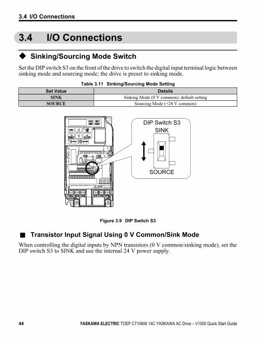
u Sinking/Sourcing Mode SwitchSet the DIP switch S3 on the front of the drive to switch the digital input terminal logic betweensinking mode and sourcing mode; the drive is preset to sinking mode.
Table 3.11 Sinking/Sourcing Mode SettingSet Value Details
SINK Sinking Mode (0 V common): default settingSOURCE Sourcing Mode (+24 V common)
DIP Switch S3SINK
SOURCE
Figure 3.9 DIP Switch S3
n Transistor Input Signal Using 0 V Common/Sink ModeWhen controlling the digital inputs by NPN transistors (0 V common/sinking mode), set theDIP switch S3 to SINK and use the internal 24 V power supply.
3.4 I/O Connections
44 YASKAWA ELECTRIC TOEP C710606 14C YASKAWA AC Drive – V1000 Quick Start Guide

DriveShielded cable
Forward run/stop
Reverse run/stop
External fault N.O.
Fault reset
Multi-speed step 1
Multi-speed step 2
Jog reference
Mul
ti-fu
nctio
n in
put
S1
SINK
SOURCE
S2
S3
S3+24V
S4
S5
S6
S7
SC
SINK
SOURCE
Figure 3.10 Sinking Mode: Sequence from NPN Transistor (0 V Common)
n Transistor Input Signal Using +24 V Common/Source ModeWhen controlling digital inputs by PNP transistors (+24 V common/sourcing mode), set theDIP switch S3 to SOURCE and use an external 24 V power supply.
3.4 I/O Connections
YASKAWA ELECTRIC TOEP C710606 14C YASKAWA AC Drive – V1000 Quick Start Guide 45
3
Elec
tric
al In
stal
latio
n

Forward run / stop
Reverse run / stop
External fault N.O.
Fault rest
Multi-step speed 1
Multi-step speed 2
Jog frequency
External power supply
Shielded cableDrive
Mul
ti-fu
nctio
n in
put
S1
S2
S3
+24V
S4
S5
S6
S7
SC
S3
SINK
SOURCE
SINK
SOURCE
+24 V
Figure 3.11 Source Mode: Sequence from PNP Transistor (+24 V Common)
3.4 I/O Connections
46 YASKAWA ELECTRIC TOEP C710606 14C YASKAWA AC Drive – V1000 Quick Start Guide

3.5 Main Frequency Reference
u DIP Switch S1 Analog Input Signal SelectionThe main frequency reference can either be a voltage or current signal input. For voltagesignals both analog inputs, A1 and A2, can be used, for current signals A2 must be used.When using input A2 as a voltage input, set DIP switch S1 to “V” (left position) and programparameter H3-09 to “0” (0 to +10 Vdc with lower limit) or “1” (0 to +10 Vdc without lowerlimit).To use current input at terminal A2, set the DIP switch S1 to "I" (default setting) and setparameter H3-09 = “2” or “3” (4-20 mA or 0-20 mA). Set parameter H3-10 = “0” (frequencyreference).
Note: If Terminals A1 and A2 are both set for frequency reference (H3-02 = 0 and H3-10 = 0), the addition ofboth input values builds the frequency reference.
Table 3.12 Frequency Reference ConfigurationsVoltage Input Current Input
Drive
Main speed frequency reference (voltage input)
Main speed frequency reference (current input)
Frequency referencecommon
+10.5 V20 mA current
0 to 10 V
+V
A1
A2
AC
Drive
Main speed frequency reference (voltage input)Main speed frequency reference (current input)
Frequency referencecommon
4 to 20 mA inputor0 to 20 mA input
+10.5 V20 mA current+V
A1
A2
AC
3.5 Main Frequency Reference
YASKAWA ELECTRIC TOEP C710606 14C YASKAWA AC Drive – V1000 Quick Start Guide 47
3
Elec
tric
al In
stal
latio
n

V I
Figure 3.12 DIP Switch S1
Table 3.13 DIP Switch S1 SettingsSetting Value DescriptionV (left position) Voltage input (0 to 10 V)I (right position) Current input (4 to 20 mA or 0 to 20 mA): default setting
Table 3.14 Parameter H3-09 Details
No. Parameter Name Description SettingRange
DefaultSetting
H3-09 Frequency ref. (current)terminal A2 signal level selection
Selects the signal level for terminal A2.0: 0 to +10 V, unipolar input (with lower limit)1: 0 to +10 V, bipolar input (no lower limit)2: 4 to 20 mA3: 0 to 20 mA
0 to 3 2
3.5 Main Frequency Reference
48 YASKAWA ELECTRIC TOEP C710606 14C YASKAWA AC Drive – V1000 Quick Start Guide