313104c matrix 3.0 basic software installation, setup and ... · matrix 3.0 basic software...
TRANSCRIPT
Matrix 3.0 Basic Software Installation, System Setup and Operation Instructions
313104CEN

Introduction
2
SECTION
1
Introduction

Introduction
3
Table of ContentsIntroduction . . . . . . . . . . . . . . . . . . . . . . . . . . . . . . . .2
Table of Contents . . . . . . . . . . . . . . . . . . . . . . . . .3General Information . . . . . . . . . . . . . . . . . . . . . .5Reference Materials . . . . . . . . . . . . . . . . . . . . . . .5Technical Support . . . . . . . . . . . . . . . . . . . . . . . .5Training Programs . . . . . . . . . . . . . . . . . . . . . . . .5
Installation . . . . . . . . . . . . . . . . . . . . . . . . . . . . . . . . .6Typical Installation . . . . . . . . . . . . . . . . . . . . . . . .7Quick Reference Installation Checklist . . . . . . . . .8System Requirements . . . . . . . . . . . . . . . . . . . .11General Matrix System Specifications . . . . . . . .11Software Installation . . . . . . . . . . . . . . . . . . . . . .13Loading the Software . . . . . . . . . . . . . . . . . . . . .13Clock and Time Zone Settings . . . . . . . . . . . . . .18Hibernation Mode . . . . . . . . . . . . . . . . . . . . . . . .19
Software Overview . . . . . . . . . . . . . . . . . . . . . . . . .24Matrix 3 Software Architecture Overview . . . . . .25Starting Matrix 3.0 . . . . . . . . . . . . . . . . . . . . . . .25Main Application Window . . . . . . . . . . . . . . . . . .26Screen Elements . . . . . . . . . . . . . . . . . . . . . . . .26System Administrator Screens . . . . . . . . . . . . . .27Go To ... Menus . . . . . . . . . . . . . . . . . . . . . . . . .27Information Panel: Device Group Status . . . . . .30Global Workorders . . . . . . . . . . . . . . . . . . . . . . .30
System Administrator Setup Screens . . . . . . . . .35System Administrator Setup Screens . . . . . . . .36General Setup Information . . . . . . . . . . . . . . . . .36System Defaults . . . . . . . . . . . . . . . . . . . . . . . . .37Events . . . . . . . . . . . . . . . . . . . . . . . . . . . . . . . .44Contact Info . . . . . . . . . . . . . . . . . . . . . . . . . . . .46User Interface Setup . . . . . . . . . . . . . . . . . . . . .48Dispense Note Fields . . . . . . . . . . . . . . . . . . . . .50
Setup Screens . . . . . . . . . . . . . . . . . . . . . . . . . . . . .51Users . . . . . . . . . . . . . . . . . . . . . . . . . . . . . . . . .52Transceivers . . . . . . . . . . . . . . . . . . . . . . . . . . . .55Fluids . . . . . . . . . . . . . . . . . . . . . . . . . . . . . . . . .59Tanks . . . . . . . . . . . . . . . . . . . . . . . . . . . . . . . . .61Device Registration and Profiles . . . . . . . . . . . .65Pump Air Control (PAC) . . . . . . . . . . . . . . . . . . .66Meters . . . . . . . . . . . . . . . . . . . . . . . . . . . . . . . .70System Layout . . . . . . . . . . . . . . . . . . . . . . . . . .75Reports . . . . . . . . . . . . . . . . . . . . . . . . . . . . . . .80
Work Orders . . . . . . . . . . . . . . . . . . . . . . . . . . . . . .91Work Orders and Job Codes . . . . . . . . . . . . . . .92

Introduction
4
Frequently Asked Questions (FAQ) . . . . . . . . . . . 97Matrix 3 FAQ . . . . . . . . . . . . . . . . . . . . . . . . . . . 98
Appendix A . . . . . . . . . . . . . . . . . . . . . . . . . . . . . . 103How to find a PC’s host name in Windows XP . 104How to find a PC’s host name in Windows Vista 106How to Register a Pump Air Control (PAC) . . . 107How to Register a Meter . . . . . . . . . . . . . . . . . 108Matrix Properties File Editor . . . . . . . . . . . . . . 109
Notes . . . . . . . . . . . . . . . . . . . . . . . . . . . . . . . . . . . 111Graco Software Warranty . . . . . . . . . . . . . . . . . . 112Graco Information . . . . . . . . . . . . . . . . . . . . . . . . 112

Introduction
5
General Information
Reference MaterialsThere are references throughout this manual to other Matrix Instruction manuals. It is strongly recom-mended that the following manuals be ordered and kept for easy reference.
• Matrix 5 and 15 Meter Instruction Manual (313046*)• Matrix Transceiver Instruction Manual (313008*)• Matrix Pump Air Control (PAC) Manual (312417*)
*Number refers to the English Language version of the instruction manual. Contact Graco Customer Service or your distributor for other language versions of the manual.
Technical Support
To identify the Graco authorized distributor closest to you, call: 1-800-533-9655 Toll Free
Training Programs
For information on available training courses, contact your distributor.

6
SECTION
2
Installation

Installation
7
Typical Installation
*Graco strongly recommends that the End User’s IS (Information Systems) professional be involved in the selection and/or purchase of the Matrix PC. See page 11, System Requirements for a complete list of com-puter requirements. See your Graco Matrix distributor for this resource if required.
FIG. 1
Ref. No. Description
A TransceiverB Matrix Software CDC Matrix 15 Meter D* Customer supplied PCE Pump Air Control (PAC)
A
C
B, D
E
Installation
8
Quick Reference Installation ChecklistThe following checklists can be used as a quick reference installation guide for the Matrix 3 System. Com-plete Matrix installation information is available in this manual beginning on page 11.
1. RF Communications Review - distributor evaluates the location of transceiver. See Matrix Trans-ceiver Instruction Manual and Matrix 15 Meter Manual.
2. Electrical Outlet Location - verify electrical outlets are conveniently located near locations for Trans-ceiver and Pump Air Control (PAC) installation.
3. Matrix Facility Layout - distributor obtains a floor plan drawing of the facility, and labels the location of Matrix components (i.e., meter number, fluid, tank number, transceiver(s), PAC). See page 7.
• Drawing should include overall shop dimensions and major building structures.
• Verify number of transceivers required.
• Complete Matrix Programming Templates - distributor and end user representative fill out the Matrix Programming Templates.
4. Computer Selection/Purchase - distributor and end user select (purchase) computers that meet Matrix requirements specified by Graco.
• Graco strongly recommends that the end user’s IS (Information Systems) professional be involved in the selection and/or purchase of PCs.
5. Create Bill-of-Materials (B.O.M.) - using the floor plan layout drawing, distributor creates the bill-of-materials and quote for the Matrix system.
• Be careful to ensure that all necessary Matrix equipment is ordered to avoid delays during installa-tion.
6. Order Matrix Equipment - distributor orders Matrix equipment and has it shipped to the distributor’s location.
• Distributor should have an office or meeting room to stage the equipment for programming.
1 3 to 4 Weeks Before Matrix Installation
Step 1 is complete

Installation
9
When the Matrix 3 hardware and software CD arrive at the distributor’s location, most of the system config-uration and setup can be done before the actual installation day at the end user’s facility. The decision to perform these steps prior to the installation site is usually a judgement call that is made by the installing distributor. For large installations, it’s prudent to do this in advance as described below.
1. Load Matrix Software to Distributor’s Server/Primary Client PC.
2. Connect Transceiver to Distributor PC - use appropriate cable for transceiver distance from PC.
3. Provide Power to Pump Air Control (PAC) - Find appropriate plug and assemble it to the PAC. Plug PAC into grounded electrical outlet.
4. Install Meter Batteries
5. RF Testing - Register meters. Verify that each PAC and meter are communicating with the trans-ceiver.
6. Export Matrix User Information to Media - Take this CD to the End User Matrix installation for importing.
• Distributor should purchase blank CDs or a USB jump drive to export the end user’s Matrix system parameters (Graco recommends putting file on C: drive, then copy to the CD or USB jump drive).
• The distributor’s PC must be loaded with the same Matrix software version as the end users PC.
• Be sure to label all meters so they match the location on the Matrix facility layout drawing (i.e., Meter 01, 5W30 and/or Tank 01, 5W30).
7. Schedule Matrix installation - arrange time with end user for Matrix installation.
2 Actions at Distributor Location when Matrix Equipment Arrives
Step 2 is complete

Installation
10
1. Install Thermal Relief and Flush Supply Lines - distributor installs the Thermal Relief filtering sys-tems on all fluids, then flushes the service lines and drops per Graco recommendations.
• Do not flush lines with Matrix meters installed.
2. Connect User Server/Primary Client PC. Load software.
• Connect the Server/Primary Client PC and monitor to the battery back-up receptacles on the Unin-terrupted Power Supply (UPS), not the surge protection side. Use the surge protection side for PC peripherals (i.e., printer, scanners).
• Configure the UPS software. For complete UPS setup information, see manufacturer’s instruction manual in the UPS box.
3. Install Matrix Software to User PC - load Matrix software to end user PC. It will automatically decompress.
4. Import Matrix User Parameters from Media - import the data to the PC from the CD or USB jump drive you created in Step 6 on page 9.
• Locate and Connect Transceiver(s) to PC - locate Transceivers in shop temporarily using dou-ble-faced tape. Connect the Transceiver(s) to the PC using RS422 cable. Graco recommends transceiver(s) be located in a central location to the Matrix components in the main body of the shop.
5. Perform Meter RF Test - After each meter is programmed, send a test dispense and verify it arrives at the meter dispense information screen with its intended meter name.
6. Install Meters - be sure to follow installation instructions.
• Do not wet-out a meter until RF is verified.
7. Install PAC - be sure to follow installation instructions.
8. Train Personnel - ensure that all personnel, administrator, and technicians are thoroughly trained on Matrix equipment.
9. Allow Matrix system to operate for 30 days - make certain there are no RF communication issues over time.
• It may be necessary to relocate the transceivers (temporarily installed with double-faced tape) to improve RF communication. When the system operates reliably for 30 days, the Matrix trans-ceiver(s) can be permanently mounted using the mounting bracket(s).
3 Actions the Day of the Installation
Step 3 is complete

Installation
11
System RequirementsGraco strongly recommends that the end user’s IS (Information System) representative be involved in the following Matrix installation activities:
• Assist with the selection and/or purchase of the Matrix PC. The PC must meet the performance speci-fications listed on pages 11.
• The IS representative should be present during Matrix software loading on the day of Matrix installa-tion.
General Matrix System SpecificationsMatrix PC software supports systems using a single PC (also referred to as a Stand Alone System).
Single PC (Standalone) Systems: Intended primarily for applications that do not require interaction with Matrix screens from multiple locations and have few meters. This type of system provides complete Matrix system functionality at one PC.
Computer Requirements
Matrix Software is PC based. It is compatible with the following operating systems: Microsoft Windows XP Home, Microsoft Windows XP Professional, Microsoft Windows Vista and Microsoft Windows 2003 Server.
Single PC Matrix Systems:Minimum Hardware Requirements
• Graco recommends using a dedicated PC to run Matrix.• 2GHz Pentium 4 (or equivalent) processor• 1GB RAM (XP or 2003 Server operating systems) or 2GB RAM (Vista)• 1024 x 768 screen resolution• 1GB free hard disk space• CD-ROM drive• One available USB port per transceiver

Installation
12
Recommendations for All Matrix Systems
• Use an uninterruptible power supply (UPS) on the Matrix server. Proper installation of a UPS on this machine will allow the server to shut down in a controlled manner when power is lost, dramatically reducing the potential for data corruption. This is important because if any Matrix database file becomes corrupt, the entire system will no longer function - that is, no fluid can be dispensed without first putting the system into emergency mode.
• Protect Matrix PC with standard security and support measures, such as:
• Keep the PC up to date with the latest patches and service packs for Windows.• Require a user name and password be provided to use the computer.• Use anti-virus software and firewalls, configuring these to still allow proper function of Matrix.
• Recommended Supplementary Software Applications (not provided by Graco):
• Adobe Acrobat Reader 7.0 or higher, for viewing reports• A spreadsheet program that can open text files in CSV format, for doing custom manipulation of
report data.
Uninstalling Matrix 3.x.x
Follow this procedure to remove Matrix software and data files stored on your computer. You will lose all Matrix system parameters and all Matrix dispense history using these procedures unless you first make a back-up of the database.
• You must have administrator privileges in order to add or remove Matrix from the computer.
• Any files you have created with Matrix since it was originally installed, such as database export files and reports, will not be removed by the uninstall program. If you wish to also remove these from your hard drive, you will have to manually do so using Windows Explorer after the uninstall program com-pletes.
Removing Matrix Software and Data Files
1. Choose Start/Control Panel from the Windows Start menu.
2. In Control Panel, double-click on “Add or Remove Programs.”
3. Scroll to “Matrix 3” in the program listing and click it once to highlight it.
4. Click on the “Remove” box.
5. In the dialog box that appears, choose “Remove” from the list of options and click the “Next” button.
6. Click “Yes” in the window that asks you to confirm your selection.
7. The uninstall program runs.
8. Click the “Finish” button.
You may or may not be prompted to reboot upon completion of the uninstall process. It is recommended that you reboot in all cases to complete the un-installation process.

Installation
13
Software InstallationThe following procedure will install the Matrix Software.
IMPORTANT:
• You may not make copies of Matrix Software for use on other PCs or for personal use. Please read the license agreement as the software loads.
• The user must be logged into Windows with Administrator privileges.• If an older version of Matrix is already installed, the older version must be uninstalled before this
one can be installed. See the Matrix Software Instruction Manual that accompanied your current Matrix installation for instructions on how to uninstall Matrix.
Loading the SoftwareNote: You must have Windows XP or Vista Administrator privileges in order to add or remove Matrix from the computer.
A Matrix Basic system supports one PC with one Matrix transceiver. The transceiver can be connected via an RS422 converter (as shown in FIG. 2) or directly to a PC USB port.
Setup Path
1. Log into Windows as an administrator.
2. Insert the Matrix CD in the CD-ROM drive.
3. Double click the Matrix3Basic.exe icon (FIG. 3).
FIG. 2
FIG. 3

Installation
14
4. Review the End User License Agreement (FIG. 4). If acceptable, select “I accept the terms of the license agreement”. After accepting the terms of the license agreement, the NEXT button becomes active. Click the NEXT button.
If you do not accept the terms of the license agreement, the installation will end. Click the BACK or EXIT button to get out of the Matrix Installation program.
5. After clicking NEXT to accept the License Agreement, the Installation Options screen shown in FIG. 5 displays. Click NEXT.
6. Chose the Destination Location. The default is C:\Program Files\Graco\Matrix3. Click the Browse but-ton, shown in FIG. 6 to select a different location.
7. Click NEXT to continue software installation and advance to the InstallShield Wizard for Matrix3 (FIG. 7). Click The BACK button to return to a previous installation screen or CANCEL to end the software installation.
FIG. 4
FIG. 5

Installation
15
8. Click NEXT. The InstallShield Wizard for Matrix3 begins the installation (FIG. 7).
FIG. 6
FIG. 7

Installation
16
9. When the Matrix Database setup screen (FIG. 8) displays, select NEXT to start the Database setup.
10. The system configures the Matrix Database. When the Matrix Transceiver screen shown in FIG. 9 dis-plays, select NEXT to start the Transceiver Driver installation.
FIG. 8
FIG. 9
Installation
17
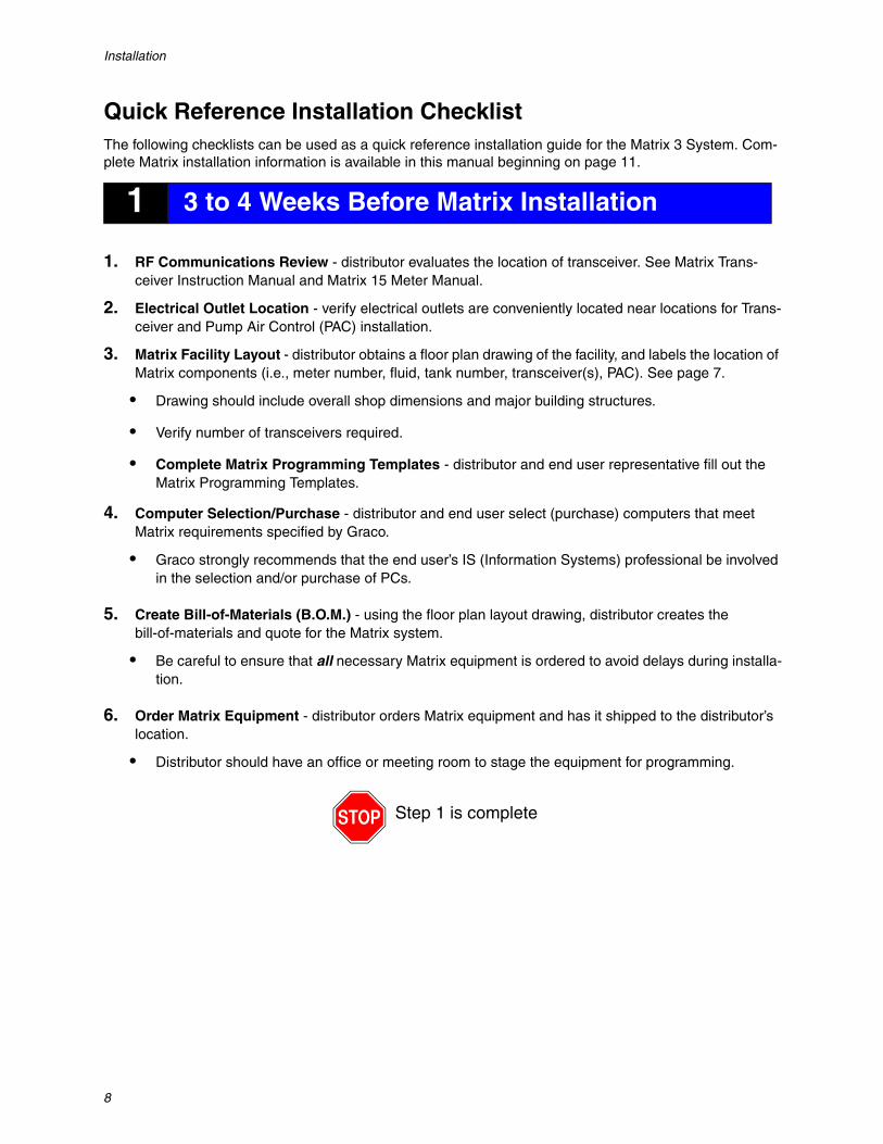
11. When the installation is complete the screen shown in FIG. 10 displays. Before Matrix functions on the PC you will have to reboot the computer. Select Yes, I want to restart my computer and click the Finish button to reboot.
Matrix creates the following shortcuts.
In Start / All Programs / Graco / Matrix:
• Matrix Client - provides the IE browser-based graphical user interface and accompanying screens. Matrix Client must be running to access Matrix Screens.
• Edit Matrix Settings - used for Exporting and Importing Matrix3 Database and setting up system properties. For a complete description of this feature see Appendix A, page 109.
• Meter Firmware Update Utility - used to update meter firmware.
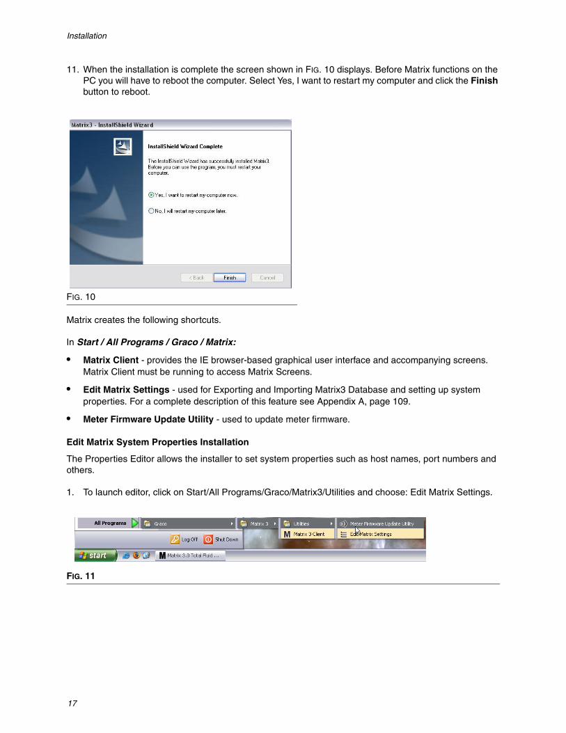
Edit Matrix System Properties Installation
The Properties Editor allows the installer to set system properties such as host names, port numbers and others.
1. To launch editor, click on Start/All Programs/Graco/Matrix3/Utilities and choose: Edit Matrix Settings.
FIG. 10
FIG. 11

Installation
18
2. The editor appears as a two-column list of system properties, with property names on the left and their editable values on the right (FIG. 12). When you select a property by clicking on it, the bottom panel of the screen shows basic information about that property.
3. To make a change, double-click on the cell in the Property Value column that you want to edit. Make the necessary change.
4. When finished, press Enter or single click on another cell.
5. Click File/Save to save your changes.
If you find the Save option disabled, it is probably because you are still in “edit mode” on the last prop-erty you edited. Single click on a different cell and try again.
NOTE: In general, its a good idea to reboot after making edits to system properties here. (See Appendix A, How to find a PC’s Host Name, page 104 for Windows XP or page 106 for Windows Vista.)
Clock and Time Zone SettingsVerify that the clock and time zone settings are correct. When the time is changed by either the PC opera-tor or automatically by the Windows operating system, (i.e., daylight savings time automated change) the PC must be restarted.
FIG. 12
Installation
19
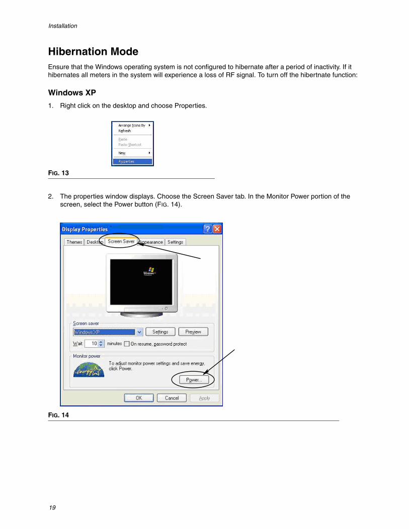
Hibernation ModeEnsure that the Windows operating system is not configured to hibernate after a period of inactivity. If it hibernates all meters in the system will experience a loss of RF signal. To turn off the hibertnate function:
Windows XP
1. Right click on the desktop and choose Properties.
2. The properties window displays. Choose the Screen Saver tab. In the Monitor Power portion of the screen, select the Power button (FIG. 14).
FIG. 13
FIG. 14

Installation
20
3. Select the Hibernate tab. Turn off hibernation by clearing (unchecking ) the Enable Hibernate check box . Click Apply and OK to close all windows (FIG. 15) and save the changes.
FIG. 15

Installation
21
Windows Vista
1. On the Windows Vista desktop select Start Search / Control Panel (FIG. 16).
2. Select the Power Options Icon (FIG. 17).
FIG. 16
FIG. 17

Installation
22
3. Select either “Balanced” or “Power Saver” power plans and then click the Change Plan Settings link to view the hibernation options (FIG. 18).
4. Change the “Put the Computer to Sleep” field to NEVER. Then select the “Change Advanced Power Settings” (FIG. 19).
FIG. 18
FIG. 19

Installation
23
5. Find “Sleep” in the scroll list (FIG. 20). Change the “Sleep after” setting to NEVER and the “Hibernate after” setting to NEVER.
NOTE: After making these changes on the screen, the Apply button will be selectable.
6. Click the Apply button to save these changes. Then click the OK button (FIG. 20).
FIG. 20

Software Overview
24
SECTION
3
Software Overview

Software Overview
25
Matrix 3 Software Architecture OverviewEvery Matrix 3 system is made up of the following components:
• Matrix Database Server. The Matrix 3 system uses MySql as its database. The database server runs as a Windows service*.
• Matrix Service Engine (MSE). This is the heart of Matrix 3; it performs all the application logic and fetches/saves data from/to the database. The MSE runs as a Windows service, dependent on the database service.
• Matrix Transceiver Server. This component translates RF communication with system devices like meters and, pump air controls (PACs) on behalf of the MSE. The Transceiver Server runs as a Win-dows service, dependent on the MSE service.
• Matrix Client. This is the Matrix 3 user interface application. When launched by the user, it will run only if it can successfully connect to the MSE.
*A Windows service is a software application that can be configured to start and run without user interven-tion. Typically, services have no means of direct user interaction and cannot be started or stopped unless a user has administrative privileges on the local machine. Matrix services are configured to start as soon as Windows starts, regardless of whether a user is logged in or not.
Starting Matrix 3.0
To start Matrix 3.0, double-click the Matrix 3.0 Client icon that was placed on your desktop during the software installation. You can also click the Start button on the Windows task bar and select All Programs / Graco / ➤Matrix 3.0 / Matrix 3.0 Client. The Matrix 3.0 Total Fluid Management System main application window opens.

Software Overview
26
Main Application WindowScreen Elements
There are 3 main screen elements available to the user on the Matrix 3 User Interface (FIG. 21).
1. System Layout Panel: The icons on the System Layout Panel are arranged in a tree-fashion. The icons displayed will vary depending on whether an administrator has logged into setup mode or the user is viewing the operating screens (“run” mode).• Setup Mode - The system layout panel shows an icon for each distinct setup area. Details about
setup mode and its screens are covered in the following chapter; the rest of this chapter assumes the application is not in setup mode.
• Run Mode - The system layout panel shows all the configured meters and tanks in the system, optionally organized by group.
2. Information Panel: The data displayed in this panel reflects the user’s selection in the system layout panel and displays information from the last 10 days. After 10 days, data is not deleted but user must run a Dispense History Report to get the information.
Data shown in the Information Panel is dependent on the selection made in the System Layout Panel.
• If a tank or meter is selected, the information panel shows status and data for that particular tank or meter.
• If a device group is selected, the information panel shows data about the tanks and meters in that group. If the Matrix System is selected, data from all tanks and meters in the system is shown.
3. System Event Log: This log is always visible and shows in chronological order system events as they occur.
FIG. 21
12
3

Software Overview
27
System Administrator Screens
Go To ... MenusThe Go To . . . menu is the only selection available on the menu bar located on the top of the Main Applica-tion Window.
Selecting Go To . . . with the mouse displays a pull-down list of available options. Items that appear dimmed are not available for use.
Setup & Reports
Once the Matrix PC software is installed, it’s necessary to synchronize the software with the other hard-ware components of the Matrix system. This is done by selecting Setup & Reports from the Go To . . . list. This section is password protected and provides access to all Matrix setup screens. Only individuals with System Administrator rights have access to this portion of the program.
1. Move the mouse pointer to the Go To . . . menu located on the Tool Bar on the top of the Main Applica-tion Window. From the drop-down menu, select Setup & Reports.
FIG. 22
FIG. 23

Software Overview
28
The popup box shown in FIG. 24 appears for you to provide a User name and Password.
2. Key in your user information. Click OK to close the screen and save the changes. For initial log on, type in matrix (lowercase) for user name and graco (lowercase) for the password. Click OK to close the screen and save the changes.
Note: To maintain the security of your system, Graco strongly recommends changing the System Administrator User name and Password during the initial setup procedure for your system. Until the User name and Password are changed the default log on matrix / graco will provide access to the Setup & Reports screens in your system. Once a new user account is created, the default matrix / graco account is disabled. Instructions for creating a new User name and Password are pro-vided in the USERS configuration screen section beginning on page 52.
FIG. 24

Software Overview
29
Hide / Display Arrows
The Main Application Window can be customized to hide the System Layout Panel and System Event Log sections of the screen if you do not want to display them. To hide these panels, click the Hide / Display arrows shown in illustration A in FIG. 25 below. Illustration B in FIG. 25 shows how the screen appears when the System layout Panel is hidden. To display the panel again use your mouse to move the cursor over the arrow pointing to the right and click the left mouse button once. The full System Layout Panel once again displays on the screen.
FIG. 25
A B
Hide/Display Arrows
Hide/Display ArrowsNote Matrix System Panelis now hidden

Software Overview
30
Information Panel: Device Group StatusThe information panel contains tabs for Global Workorders (when Global Workorders is enabled), Fluid Dispenses and Tank Levels.
Records are only displayed for the last ten days. After ten days, the information is deleted from the screen. The System Administrator can retrieve historical information by creating a report.
Global WorkordersNOTE: The Global Workorders tab only appears if Global Workorders is enabled on the System Default setup screen, page 37.
If the tab is not selected, position cursor over the Global Workorders tab and click left mouse button once to select it.
The Global Workorders tab displays a list of all Global Workorders that have been added to the Global Workorder Queue. At this point these workorders have not been assigned to any specific meter - they are simply entered and define the quantity of a specific fluid. Only meters that are connected to those fluids can view these global work orders.
• Timestamp: displays the month, date, year and time that the event took place• Work Order: number assigned to the work order• Job Code: number assigned to the job code• Amount: quantity dispensed by the meter, measured as either Pints, Quarts, Gallons or Liters• Fluid: type of fluid dispensed • Group: defines which Meters in the Matrix System were assigned the Global Workorder and per-
formed the dispenses
FIG. 26

Software Overview
31
Dispenses TabIf the Dispenses tab is not selected, position cursor over the Dispenses tab and click left mouse button once to select it.
The Dispenses tab displays three tables: Pending Dispenses, Completed Dispenses and Dispense Notes (described on the following pages).
The columns displayed in the Pending Dispenses and Completed Dispenses tables are configurable. Col-umns can be hidden or shown, the column’s sort order can be changed according the end user’s needs. This configuration is done in the Matrix System Setup Screens, User Interface Setup, page 48. The screen configuration affects all Matrix clients in the system.
Pending Dispenses: Shows all started, but not completed dispenses made by any meter in the system. When the dispense is completed, it is removed from the pending table and added to the top of the Com-pleted Dispenses table. A user can view notes for individual dispenses by selected a completed dispense row.
• Timestamp: displays the day, month, date, time, and year that the dispense took place• Meter Name: specific name assigned by the System Administrator on the Setup screens to identify
a specific meter• Amount: quantity dispensed by the meter, measured as either Pints, Quarts, Gallons or Liters• Fluid: type of fluid dispensed • Work Order: number assigned to the work order• Job Code: number assigned to the job code• Battery: amount of battery life remaining
FIG. 27

Software Overview
32
Completed Dispenses: List of all dispenses that have been completed by all meters in the system.
• Timestamp: displays the month, date, year and time that the event took place• Meter Name: specific name assigned by the System Administrator on the Setup screens to identify
a specific meter• Amount: quantity dispensed by the meter, measured as either Pints, Quarts, Gallons or Liters• Fluid: type of fluid dispensed • Work Order: number assigned to the work order• Job Code: number assigned to the job code• Battery: amount of battery life remaining
Dispense Notes: Additional, supporting information supplied by the technician related to a dispense. Dis-pense Notes can only be added at the PC..
FIG. 28
FIG. 29

Software Overview
33
Events LogThe lower portion of the Screen contains the Events Log, a report of system-wide events that have occurred and the dates and times for those events. This information can be hidden if you do not wish to routinely display it using the Hide / Display Arrows (see Hide / Display Arrows on page 27).
• Timestamp: displays the month, date, year and time that the event took place.• Event: lists type of event that occurred.• Detail: additional information related to the event.• Device: equipment that triggered the event report: meter, tank, PAC.• Location: location of device in the Matrix Operating System.
FIG. 30

Software Overview
34
About Matrix
The screen in FIG. 31 displays. No User Name or Password are required to display this screen.
Exit
Closes the Matrix User Interface Program. The Database, MSE, Transceiver, and Server continue to run.
FIG. 31

System Administrator Setup Screens
35
SECTION
4
System Administrator Setup Screens

System Administrator Setup Screens
36
System Administrator Setup ScreensThe System Administrator has access to the following screens. A detailed description of each screen, its purpose and function are provided on the following pages:
• Users - page 52: Used to add new users, modify or remove users. Also assigns each user a name, PIN information and security level.
• Transceivers - page 55: Sets Transceiver ID to enable the Matrix PC to communicate with the hardware components in the Matrix system.
• Fluids - page 59: Used to add, edit or remove fluids from the system.
• Tanks - page 61: Defines the profile for each geometric storage device in the Matrix system.
• Pump Air Controls - page 66: Defines the profile for each Pump Air Control used in the Matrix system.
• Meters - page 70: Defines the profile for each meter used in the Matrix system.
• System Layout - page 75: Area where System Administrator defines how devices appear to the end user on the screen.
• Reports - page 80: Data collected by Matrix while it is running related to PIN Activity, PRA Activity, Cur-rent Tank Volume, Dispense History and System Configuration. These Reports are explained in detail in the Reports Section of this document, beginning on page 80.
General Setup Information• Screens are read only (not editable) unless you click a Modify button to bring up an edit dialog window.
• Changes/edits take affect after the OK button is clicked on the modify dialog window. Clicking the Can-cel button abandons your changes.
• In setup mode, the top-level Matrix System icon in the system layout panel represents configuration settings that are global (system-wide). The following tabbed sections are available:
✓ System Defaults - page 37✓ Events - page 44✓ Contact Information - page 46✓ User Interface Setup - page 48✓ Dispense Notes - page 50

System Administrator Setup Screens
37
System Defaults ______________________________________Select the System Default tab to display the System Default screen shown in FIG. 32.
In this view the screen appears in a Read Only format. Click the modify button to make changes to the fields.
The parameters set on this screen determine the defaults that appear elsewhere in the application; but they do not limit the options available.
For example: The Measurement System shown in FIG. 32 is currently set to English. (The other available option in this field is Metric units.) If English is set, the default volumetric units will be Quarts on all other screens. If Metric is set, the default volumetric units will be Liters.
When necessary, you can override the default setting and choose other units that are more appropriate for the specific system component on that component's setup screen.
FIG. 32

System Administrator Setup Screens
38
To setup the defaults on the System Default screen, click the Modify button. The System Default change screen shown in FIG. 33 displays.
System Default Settings
• Measurement System: From drop down menu choose between two options - English or Metric.
• Meter Security Type: From drop down menu select the type of meter security you are requiring.
• PIN Code - Meter requires user to provide a 4-digit PIN code before it can be used to dispense fluid.
• Parts Room Authorization (PRA) - User must request authorization from the system administra-tor before each dispense. The system administrator can either ACCEPT or DENY the request. If the request is DENIED, the user will NOT be able to dispense fluid.
• System Monitoring - No meter dispensing security. Prior authorization or user identification is not required prior to any fluid dispense.
• System Emergency Code: Entering the correct Emergency Code at the meter enables fluid to be dis-pensed in the event the meter loses RF communication with the PC. Work flow is not interrupted while the problem is being corrected. The meter comes from the Graco factory set in Emergency Mode with the default Emergency Code 4357. To ensure security and prevent unauthorized dispenses, Graco recommends changing this security code to another number when it is installed.
When a meter is in emergency mode, the meter continues to dispense accurately and consistently, but it does not report what it dispenses to the PC. It behaves just like a stand-alone, electronic, preset meter. Any security the meter had is turned off. If the meter was in Work Order mode, work orders are also turned off.
The system emergency code can be changed at any time.
IMPORTANT: When the emergency code is changed, every meter in the system must be re-regis-tered.
FIG. 33

System Administrator Setup Screens
39
• Use Vehicle ID’s: Must be set to NO. Using Vehicle ID’s is not an available option for Matrix 3 Basic operating systems.
• Automatic Per Dispense Report: YES/NO option. When YES is selected, Matrix will generate and send to the Dispense Report Printer a short, concise report after every fluid dispense in the system. The report will contain a dispense timestamp, type of fluid, dispense amount, work order and job code (if used) and technician’s name (if PIN code is used).
If NO is selected, this report will not be generated.
• Dispense Report Printer: Sets the printer that the Automatic Per Dispense Report (above) is sent to for printing. This printer must be either physically attached to the computer running the Matrix Service Engine (MSE) or the MSE must be configured to view the list of available printers. Only users with administrative privileges can configure the MSE.
NOTE: This procedure is the same for computers running Windows XP or Vista operating systems.
a. Right click the My Computer icon on the desktop; then click Manage (FIG. 34).
b. Double click on Services and Applications (FIG. 35).
FIG. 34
FIG. 35

System Administrator Setup Screens
40
c. Double click on Services (FIG. 36).
d. Double click Matrix System Engine on the Services list (FIG. 37).
e. Select the Log On tab (FIG. 38).
FIG. 36
FIG. 37
FIG. 38
System Administrator Setup Screens
41
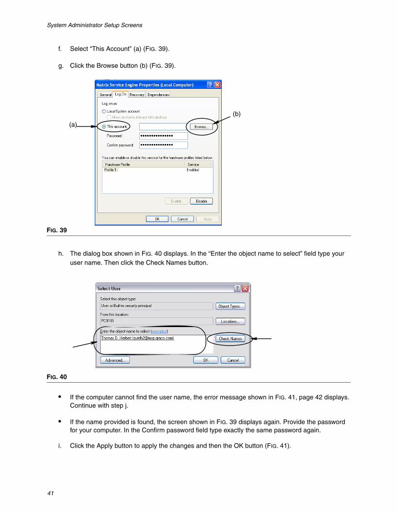
f. Select “This Account” (a) (FIG. 39).
g. Click the Browse button (b) (FIG. 39).
h. The dialog box shown in FIG. 40 displays. In the “Enter the object name to select” field type your user name. Then click the Check Names button.
• If the computer cannot find the user name, the error message shown in FIG. 41, page 42 displays. Continue with step j.
• If the name provided is found, the screen shown in FIG. 39 displays again. Provide the password for your computer. In the Confirm password field type exactly the same password again.
i. Click the Apply button to apply the changes and then the OK button (FIG. 41).
FIG. 39
FIG. 40
(a)
(b)

System Administrator Setup Screens
42
j. If the computer cannot find your user name the error message shown in FIG. 42 displays. Check the select object types and location for accuracy and try entering your user name again. If you still receive the error message, contact your IT person for assistance.
k. Click the Restart Service link (FIG. 43).
FIG. 41
FIG. 42
FIG. 43

System Administrator Setup Screens
43
• Use Global Work Orders: YES/NO option. When YES is selected, only work orders created at the PC as Global Work Orders can be dispensed. Can select work orders at the meter but cannot create work orders at the meter.
Note: If a valid workorder is typed in at the meter and the workorder uses that meter’s fluid and is assigned to that meter’s device group, the system will move the workorder to that meter.
Log In Behavior:
• Work Order Entry Authentication - Checking the box requires user to enter their user name and password for every work order they enter into Matrix. If it is not checked, Matrix allows work order entry indefinitely after a successful initial login.
Note: Matrix does not require using work orders.
Click the OK button to close the screen and save the changes.

System Administrator Setup Screens
44
Events ______________________________________________Select the Events tab to display the Events screen shown in FIG. 44. The Events screen is divided into three main categories: Tank Level Monitor Events, Meter Events and General System Events, the Tank Level Monitors Events category is not available to Matrix 3 Basic software users. The Meter Events and General System Events categories each contain a list of possible alarm events.
The system can be configured to provide either an audible or visual signal or both.
The DISPLAY check box does not affect whether or not an event appears on the bottom of the screen in the system Event Log; events will always appear there. The check box only determines whether a pop-up display windowing showing the event should be generated when the event occurs.
In this view the screen appears in a Read Only format.
Click the Modify button to make changes to the fields on this screen.
FIG. 44

System Administrator Setup Screens
45
Selecting DISPLAY Events
Click the modify button to display the Events change screen shown in FIG. 45. The green check boxes in the DISPLAY column indicate the “events” selected for visual notification when an alarm event occurs. In this mode, any box in the DISPLAY column can be checked or unchecked. Boxes that are not checked will not provide a visual alarm when an alarm event occurs related to that item. In this mode, AUDIBLE alarms cannot be modified.
Enable Audible Events
To enable the Audible Events column, check the Enable Audible Events checkbox on the top of the screen (FIG. 46).
When this box is checked, check marks appearing in the Audible Events column become green. Any box in the AUDIBLE column can be checked or unchecked. Boxes that are not checked will not provide an audible alarm when an alarm event occurs related to that item.
Click the OK button to close the screen and save the changes.
FIG. 45
FIG. 46

System Administrator Setup Screens
46
Contact Info _________________________________________Select the Contact Info tab to display the Contact Info screen shown in FIG. 47. This tab provides the cus-tomer with a quick reference resource containing information about who to contact for assistance and/or questions about their Matrix 3 system.
The Contact Info screen is divided into two sections: Installation Information and Distributor Information. In this view the screen appears in a Read Only format.
FIG. 47
System Administrator Setup Screens
47
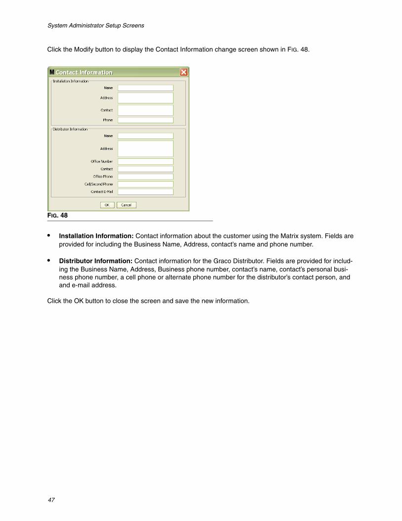
Click the Modify button to display the Contact Information change screen shown in FIG. 48.
• Installation Information: Contact information about the customer using the Matrix system. Fields are provided for including the Business Name, Address, contact’s name and phone number.
• Distributor Information: Contact information for the Graco Distributor. Fields are provided for includ-ing the Business Name, Address, Business phone number, contact’s name, contact’s personal busi-ness phone number, a cell phone or alternate phone number for the distributor’s contact person, and and e-mail address.
Click the OK button to close the screen and save the new information.
FIG. 48

System Administrator Setup Screens
48
User Interface Setup __________________________________Select the User Interface Setup tab to display the User Interface Setup screen shown in FIG. 49. The User Interface Screen is used to tailor the appearance of specific data tables shown on the run screens. The system administrator has the ability to select which columns should be visible/hidden and the table’s sort order. The screen is divided into three sections.
• Table Name: a list of configurable data tables on Operation Screens
• Columns for Table: Column Headings currently associated with the highlighted table and the order they appear.
• Under the Location on Display column is a list of the screens those tables appear on.
In this view the screen appears in a Read Only format.
FIG. 49

System Administrator Setup Screens
49
To configure a table, use the mouse to highlight a table on the list. Then click the Modify button. The User Interface Setup Screen shown in FIG. 50 displays.
• Available Columns - List of columns available for display and sorting, that are not currently selected .
• Display Columns - The subset of all available columns that have been selected for display in the table.
• Sort Columns - The columns by which the rows of data in the tables are sorted. These columns are arranged in order to determine which column to sort first, second, third, etc.
To move a Column Heading between columns, use the mouse to select the item and the left and right arrows between the columns to add or remove the item.
For example in FIG. 50, if you want to add “Entered” shown under the Available Columns heading to the Display Columns group, select “Entered” on the list with the mouse and then click the right pointing arrow between the two columns. “Entered” is then moved to the Display Columns and becomes a displayed field on the User Interface Table you are configuring (in this FIG. 50 example, the Completed Dispenses table).
As a second example, if you want to remove “Job Code” shown under the Display Columns heading, use the mouse to select it and then click the left-pointing arrow between the Display Columns column and the Available Columns column. “Job Codes” is then removed from the Display Columns and is no longer a part of the User Interface Table you are configuring.
Finally, if you want to add Battery to the Sort Columns column, use the right pointing arrow to add it to the list.
• Display Order (drag and drop) - Displays the items listed in the Display Columns section of the screen. Items can be rearranged by using the mouse to drag and drop headings into the desired display order.
Click the OK button to close the screen and save the new information. Repeat this process for each table listed under the User Interface Tables heading.
FIG. 50
System Administrator Setup Screens
50
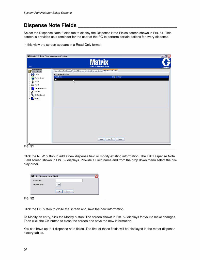
Dispense Note Fields __________________________________Select the Dispense Note Fields tab to display the Dispense Note Fields screen shown in FIG. 51. This screen is provided as a reminder for the user at the PC to perform certain actions for every dispense.
In this view the screen appears in a Read Only format.
Click the NEW button to add a new dispense field or modify existing information. The Edit Dispense Note Field screen shown in FIG. 52 displays. Provide a Field name and from the drop down menu select the dis-play order.
Click the OK button to close the screen and save the new information.
To Modify an entry, click the Modify button. The screen shown in FIG. 52 displays for you to make changes. Then click the OK button to close the screen and save the new information.
You can have up to 4 dispense note fields. The first of these fields will be displayed in the meter dispense history tables.
FIG. 51
FIG. 52

Setup Screens
51
SECTION
5
Setup Screens

Setup Screens
52
Users_______________________________________________1. Select Users from the list on the Matrix System Panel.
The Users screen shown in FIG. 54 displays a list of users entered into the system. It is used to add new users and (when required) to set the user’s security level, PIN numbers and Passwords.
FIG. 53
FIG. 54

Setup Screens
53
2. Select the Add New button.
3. The Edit User screen shown in FIG. 55 displays. This screen is used to provide the User’s Name, PIN (Personal ID Number), Security Level, Real Name (optional) and when needed, a Password.
• User Name - system-wide, unique user name. If a user will have Work Orders or Administrator security level, it is convenient to have a short, easily remembered user name, since it needs to be typed in for each access to work orders and system setup screens. This name is what appears in the “Entered” column under the User Interface Setup.
• PIN - system-wide, unique 4-digit number between 0000-9999. If a meter is configured to use PIN codes, this is the number that allows access to dispense fluid from the meter.
• Security Level - can be one of three possible settings:
a. Basic: can monitor Matrix status screens and operate meters. Basic users will not be prompted for a password because they can only view the system and meters.
b. Work Orders: allows all Basic privileges, plus allows work order entry at the PC
c. Administrator: has complete access to all components of the software. More than one person can have Administrator security access. However, as soon as one Administrator user is created, the default matrix / graco user name and password will be disabled. Users with Administrator security level have special responsibility to keep track of their user name and password and keep it secure. If you misplace your system administrator password, call the Graco Lubrication Equipment Support Team at 1-800-533-9655 from 7:30 am to 5:00 pm CST.
d. Global Work Orders: Allows all Basic privileges plus Global Work Order entry.
• Real Name - optional field for identifying user when something other than the user’s real name is supplied for the User Name field. This name appears on the Dispense History Report for Techni-cian.
• Password - used with the User Name to access work order screen (for users who have Work Order security level or higher) and setup screens (for Administrators).
FIG. 55
Setup Screens
54
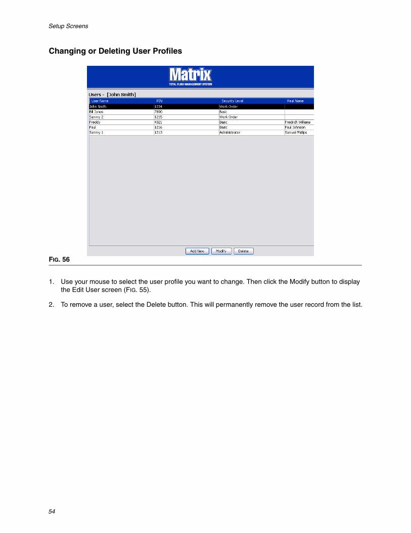
Changing or Deleting User Profiles
1. Use your mouse to select the user profile you want to change. Then click the Modify button to display the Edit User screen (FIG. 55).
2. To remove a user, select the Delete button. This will permanently remove the user record from the list.
FIG. 56

Setup Screens
55
Transceivers _________________________________________1. To display the Transceiver Screen, select Transceivers from the list on the Matrix System Panel.
Transceivers use a radio frequency (RF) signal to facilitate communication between the Matrix PC and other hardware components in the Matrix System. The number of transceivers a Matrix System can sup-port is determined by the type of system (Basic/Professional/Premier) you have. Basic systems can only have 1 transceiver. Each transceiver can support up to 150 RF devices.
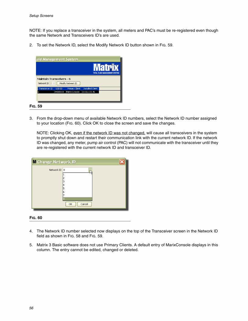
The Matrix 3 Basic software Transceiver screen shown in FIG. 58 is used to:
• Set the system’s Network ID (used by all transceivers. )• Set the individual transceiver’s Transceiver ID
When you plug in a new transceiver, it appears as a new row on the PC Transceivers screen. If you exceed the allowed number of transceivers for your system, they will not appear on the screen.
The Transceiver instruction manual provides complete information about transceiver installation and regis-tration with the Matrix PC.
FIG. 57
FIG. 58
Setup Screens
56
NOTE: If you replace a transceiver in the system, all meters and PAC’s must be re-registered even though the same Network and Transceivers ID’s are used.
2. To set the Network ID, select the Modify Network ID button shown in FIG. 59.
3. From the drop-down menu of available Network ID numbers, select the Network ID number assigned to your location (FIG. 60). Click OK to close the screen and save the changes.
NOTE: Clicking OK, even if the network ID was not changed, will cause all transceivers in the system to promptly shut down and restart their communication link with the current network ID. If the network ID was changed, any meter, pump air control (PAC) will not communicate with the transceiver until they are re-registered with the current network ID and transceiver ID.
4. The Network ID number selected now displays on the top of the Transceiver screen in the Network ID field as shown in FIG. 58 and FIG. 59.
5. Matrix 3 Basic software does not use Primary Clients. A default entry of MarixConsole displays in this column. The entry cannot be edited, changed or deleted.
FIG. 59
FIG. 60
Setup Screens
57
Modifying Transceiver Information
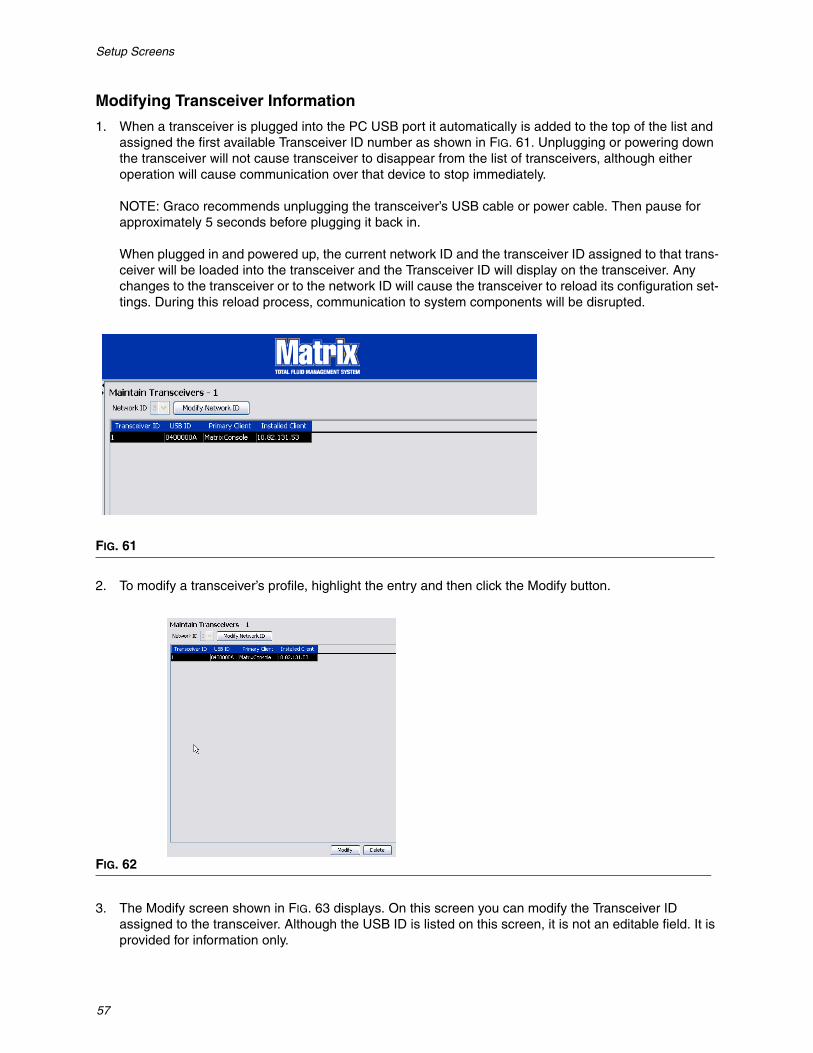
1. When a transceiver is plugged into the PC USB port it automatically is added to the top of the list and assigned the first available Transceiver ID number as shown in FIG. 61. Unplugging or powering down the transceiver will not cause transceiver to disappear from the list of transceivers, although either operation will cause communication over that device to stop immediately.
NOTE: Graco recommends unplugging the transceiver’s USB cable or power cable. Then pause for approximately 5 seconds before plugging it back in.
When plugged in and powered up, the current network ID and the transceiver ID assigned to that trans-ceiver will be loaded into the transceiver and the Transceiver ID will display on the transceiver. Any changes to the transceiver or to the network ID will cause the transceiver to reload its configuration set-tings. During this reload process, communication to system components will be disrupted.
2. To modify a transceiver’s profile, highlight the entry and then click the Modify button.
3. The Modify screen shown in FIG. 63 displays. On this screen you can modify the Transceiver ID assigned to the transceiver. Although the USB ID is listed on this screen, it is not an editable field. It is provided for information only.
FIG. 61
FIG. 62

Setup Screens
58
NOTE:
• Clicking OK, even if the transceiver ID was not changed, will cause this transceiver to promptly shut down and restart its communication link with the current network ID and transceiver ID. If the transceiver ID was changed, any meter and pump air control (PAC) in the system will not commu-nicate with the transceiver until they are re-registered with the current network ID and transceiver ID. When this restart cycle is complete, the transceiver will display its current transceiver ID.
• The Primary Client field appearing on this screen cannot be changed. MatrixConsole is the only option available to Matrix 3 Basic software users.
4. To modify the Transceiver ID, click the arrow to display the drop-down menu. From the drop-down menu select a Transceiver ID number (FIG. 64). Click OK to close the screen and save the changes.
5. To completely remove a Transceiver from the list, highlight the Transceiver on the main Transceivers screen. Click the Delete button. The Transceiver is then permanently deleted from the system. If the transceiver is powered down (or unplugged from PC) and then powered back up (or plugged in), the transceiver will again appear in the transceiver list.
FIG. 63
FIG. 64

Setup Screens
59
Fluids ______________________________________________1. Select Fluids from the list on the Matrix System Panel.
The screen shown in FIG. 66 displays a list of fluids that are entered into the system. It is used to add, edit or remove a fluid from the system profile.
FIG. 65
FIG. 66

Setup Screens
60
2. To create a profile and add a new Fluid to the Matrix system, click the Add New button.
3. On the Add Fluid screen type in a name for the fluid in the Fluid field (FIG. 67). (40 character maximum. For ease of identification and reporting, it is recommended that short Fluid Names are used.
4. Then choose a fluid type: anti-freeze 50/50, Gear Lube or Oil/ATF from the pull-down menu, that corre-sponds with the Fluid Name you entered. Click OK to close the screen and save the changes.
5. The Fluid information displays on the Fluids screen as shown in FIG. 69.
6. To modify the name assigned to a fluid or the type of fluid assigned to a name (FIG. 69) highlight the entry listed on the main Fluids screen.
7. Click the Modify button to display the Edit Fluid screen shown in FIG. 70. When you have finished mak-ing changes, click OK to close the screen and save the changes.
8. To permanently delete a fluid from the list, on the main Fluids screen, highlight the item you no longer want on the list. Then click the Delete button.
FIG. 67
FIG. 68
FIG. 69
FIG. 70

Setup Screens
61
Tanks _______________________________________________1. Select Tanks from the list on the Matrix System Panel.
The screen shown in FIG. 72 displays. It is used to add, edit, remove and create a profile for the tanks in a Matrix system. A tank is a geometric shape that holds the fluid dispensed by a Matrix meter. You will need to complete the Fluids Profile described on page 59 before you can create the Tank profile(s) for your sys-tem.
FIG. 71
FIG. 72

Setup Screens
62
2. Click the ADD NEW button to create a profile and add a new Tank to the Matrix system
3. The Edit Tank Profile screen shown in FIG. 73 displays.
• Tank Name: provide a name to identify the tank.
• Fluid Name: from the pull-down list select the type of fluid the tank will hold. This field is created from the information provided on the Fluids screen described on page 59. (40 character maximum.)
• Tank Capacity: provide a numeric entry representing the number of Gallons or Liters the tank will hold.
• Units: from the pull-down list select the volumetric measurement the system is using - either Gallons or Liters.
• Length Units: from the pull-down list select the length measurement unit the system is using - either Inches or Centimeters.
• Tank Warning Level: works in tandem with the Tank Level Warning Type field to set the percent of full (High) or empty (Low) criteria. For example, if the Tank Level Warning Type is set to High - 20%, an alarm is sent when the fluid in the tank reaches a level of 80% full (20% from the top of the tank). If the Tank Level Warning Type is set to Low - 20%, an alarm event is sent when the fluid in the tank reaches a level of 80% empty (20% from the bottom of the tank).
• Tank Level Warning Type: works in tandem with the Tank Level Warning field. Select either High or Low (see Tank Warning Level for additional information).
FIG. 73

Setup Screens
63
• Tank Shape: select either vertical (default), cylinder or obround. Additional dimension information is required for Cylinder and Obround shaped tanks (See FIG. 74).
NOTE:
• If a tank is cylindrical, but sits upright, select vertical.• Cylindrical tanks can’t have belled ends.
Tank Shape
Vertical tanks use the tank capacity to calculate tank volume. Cylindrical and obround tanks use the tank dimensions to calculate tank volume.
1. When all required information for the tank profile has been supplied, click OK to close the screen and save the changes. The tank is added to the list as shown in FIG. 75.
2. To modify a Tank profile (FIG. 75) highlight the entry listed on the main Tanks screen as shown in FIG. 75.
FIG. 74
FIG. 75
Vertical Shape
Cylinder Shape
Obround Shape

Setup Screens
64
3. Click the Modify button shown in FIG. 76 to display the Edit Tanks screen. When you have finished making changes, click OK to close the screen and save the changes.
4. To permanently delete a Tank from the list, on the main Tanks screen, highlight the item you no longer want on the list. Then click the Delete button (FIG. 76).
Note: When the Run Screens are displayed the Tanks appear in the Matrix System Panel as shown in FIG. 77.
FIG. 76
FIG. 77
Setup Screens
65
Device Registration and Profiles The following section uses the term “device” to generically refer to a Matrix meter or pump air control (PAC) in explaining how these electronic components are identified and configured in a Matrix system.
A unique device ID is embedded into every Matrix device and is the means by which the device success-fully communicates with the PC.
The Matrix system installer/administrator must create a profile definition for every single device in the sys-tem. These profiles are created and maintained in the Matrix PC setup screens, organized by device type (meter, pump air control).
The general method for configuring a Matrix system is to:
1. Create a profile for each device. This profile defines what the device is named and how it should func-tion within the system.
2. Register each device with the Matrix software. In the registration process, the device tells the PC what type of device it is and it’s device ID.
3. Link each device ID to the proper device profile. This allows the PC to load the right profile into each device.
Once a device’s device ID is linked to a profile, the profile is loaded into the device over the wireless trans-ceiver link the next time it communicates with the PC. Whenever the device profile is changed, the new pro-file is again loaded into the device, requiring no user interaction to keep the device functioning according to its defined profile. Once a device ID is linked to a profile, it cannot be assigned to another profile.
The timing of steps 1 and 2 can be interchanged; it’s not critical that the profiles be defined first or the devices are registered first. What is important is that, for a specific device, both are done before trying to accomplish step 3.
Note that in all but the smallest systems, it is a good idea to make a map of the Matrix system that identi-fies every Matrix component and corresponding device ID. This map will be an invaluable reference to cor-rectly map device IDs to profiles. Initially, the installer is advised to learn how this process works by experimenting with one or two devices before attempting to configure dozens of devices.
Profile record color-coding legend:
• Yellow - Indicates profile is in the READY state. The profile is not yet linked to a device ID.• Green - Indicates profile is in the ASSIGNED state. The profile has been assigned to a device ID,
but it is not yet loaded into the device.• White - Indicates profile is in the CONFIGURED state. The profile has been linked to a device and
the profile has been loaded into the device.

Setup Screens
66
Pump Air Control (PAC)________________________________1. To display the Pump Air Control setup screen, select Pump Air Control from the list on the Matrix Sys-
tem Panel.
The screen shown in FIG. 79 is used to name, link, unlink and modify a Pump Air Control (PAC) in a Matrix system. You can only have one PAC for each pump in your system.
2. Click the Add New button.
3. The Add PAC Profile screen is shown in FIG. 80. On this screen you are prompted to name the PAC. After you type the name of the PAC in the field, click OK to close the screen and save the changes.
FIG. 78
FIG. 79

Setup Screens
67
You will notice that information cannot be typed in the PAC ID field. The PAC ID is unique to a specific PAC and appears in this field when you click the Link button creating the Link between the PAC and the Matrix PC.
4. After you have named the PAC, click the link button. The Profile/ID Assignment screen shown in FIG. 81 displays. From the list of registered Pump Air Controls, select a PAC from the list. Click OK to close the screen and save the changes. A complete description of the PAC registration procedure is provided in the Pump Air Control instruction manual. Instructions are also provided in the How to Register a Pump Air Control section in Appendix A of this manual on page 107.
FIG. 80
FIG. 81

Setup Screens
68
5. The PAC ID number displays in the PAC ID field (FIG. 82). Click OK to close the screen and save the changes.
Notice the “Link” button in FIG. 82 is no longer active and instead an “Unlink” button is active. Clicking the “Unlink” button breaks the association between the PAC and the Matrix PC.
6. The Linked PAC appears on the main screen as shown in FIG. 83.
FIG. 82
FIG. 83

Setup Screens
69
7. To modify the name of the PAC click the “Modify” button.
8. The Edit PAC Profile box shown in FIG. 84 displays. To change the PAC name, type a new name in the PAC Name box and click OK to close the screen and save the changes.
This screen can also be used to “Unlink” the registered PAC by clicking the “Unlink” button.
FIG. 84

Setup Screens
70
Meters ______________________________________________1. To display the main Meters setup screen, select Meters from the list on the Matrix System Panel (FIG.
85).
The screen shown in FIG. 86 is used to add, edit, remove and create a profile for the Meters in a Matrix sys-tem.
FIG. 85
FIG. 86

Setup Screens
71
2. Click the Add New Button to create a profile and add a new Meter to the Matrix system.
3. The Add Meter Profile screen shown in FIG. 87 displays.
• Meter Name: Type in a name for the meter (typically a number, maximum 11 characters).
• Meter ID: The Meter ID is unique to a specific meter and appears in this field on the PC after you click the Link button which creates the Link between the meter and the Matrix PC.
• Tank: Click the Tank drop down list to select the tank you will be dispensing from with this meter.
• Units: Click the Units drop down list to select the dispense measurement unit.
FIG. 87

Setup Screens
72
• Calibration - Automatically displayed when a tank is selected. These values represent a global cali-bration default setting, meaning the calibration number appears on all meter setup screens. You can change the calibration for an individual meter using this screen. To change the meter’s calibration:
a. Dispense fluid into a clean, calibrated, volumetric measuring flask until the meter display indicates 1 quart (Metric, 1 liter) of fluid has been dispensed.
b. Compare factor from Table 1 (below) to your meter.
Your calibration number may vary slightly due to temperature or rate of flow.
• Mode: Click the Meter Mode drop down list to select Manual, Preset or Restricted Preset.
• Manual - amount dispensed is determined by the operator.• Preset - the meter is programmed for a default preset volume. The preset volume can be modified
on a work order to work order basis when sending work orders from the PC. The preset volume can always be increased or decreased by any amount at the meter prior to beginning the dispense. Also see Topoff Parameters covered later in this meter section.
• Restricted Preset - exactly the same as Preset mode, except the preset volume cannot be increased at the meter.
• Topoff: A percentage of the preset volume that can be (at the meter operator’s discretion) dispensed after the preset amount has been reached. The options are 0, 5, 10, 15, 20, 25 and unlimited.
• Preset: Three default mounts of fluid that can be selected for dispense if Preset or Restricted Preset is selected.
• Security Type: Determines how fluid can be dispensed using the meter.
• PIN Code: PIN Code (Personal Identification Number) means that a four digit number must be entered at the meter before every new dispense to obtain dispense authorization.
• Parts Room Authorization: This mode provides highest level of security and requires a Parts Room Administrator to authorize each dispense.
• System Monitoring: When system monitoring is selected, no security authorization is required prior to making a dispense. Any amount of fluid dispensed is automatically sent by the meter to the PC where it is recorded for future reference.
Table 1:
Calibration
Fluid English Metric
Oil (10W30) 172 182
Gear Lube 172 182
ATF 172 182
Antifreeze 150 168

Setup Screens
73
• Emergency Code - Four digit emergency override. This number is used at the meter to override all meter programming should there be a loss of RF signal. It allows the user to continue dispensing fluid even though the meter is not receiving an RF signal.
NOTE: If the system emergency code is used to override the meter program, the meter MUST be reg-istered into the system after the RF signal has been restored.
• Use Work Orders - Choose Yes or No from the drop down list.
• Yes - the meter will use work orders. In order to dispense fluid from this meter, the user must enter a work order at the PC or meter (when Work Order Entry is allowed at the meter). The meter oper-ator selects the work order from a list that displays on the meter screen. The PC tracks the fluid dispensed with this work order number.
A complete description of the Work Orders can be found in the Matrix 15 Meter instruction manual 313046 and in the Assigning Work Orders at the PC section of this manual beginning on page 92.
• No - the meter will not use work orders. Fluid dispenses will only be tracked by the meter.
Depending on which security type is selected there may be some meter/PC interaction that hap-pens to be able to dispense fluid; this setting only specifies whether the dispensed fluid is tracked by a work order.
• Work Order Entry at Meter - Choose Yes or No from drop down list. This parameter is only selectable if Use Works Orders is Yes.
• Yes - enter a work order on the meter keypad. With this setting work orders can be sent from the PC or entered at the meter.
• No - work orders cannot be entered at the meter, they can only be sent from the PC.
• Battery Warning Level - Choose when a warning is sent to the PC that the battery strength is weak-ening. Can select to be notified when the battery level is down to 5, 10, 15, 20 or 25 percent.
• PAC - Selects which PAC (pump air control) is used by the specific meter. None is the default option since a Matrix system does not require the use of PAC.
NOTE: If any field in the profile is changed, changes will not be loaded into the meter until it goes to sleep and wakes up again or is registered again.
Setup Screens
74
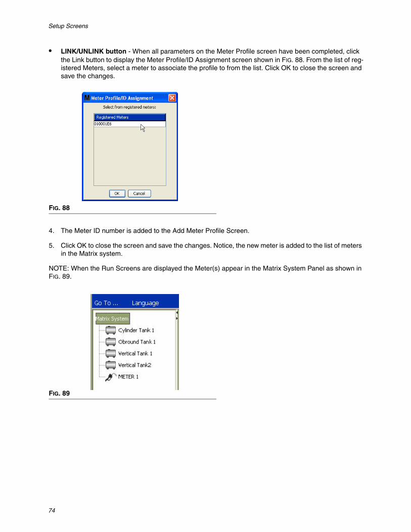
• LINK/UNLINK button - When all parameters on the Meter Profile screen have been completed, click the Link button to display the Meter Profile/ID Assignment screen shown in FIG. 88. From the list of reg-istered Meters, select a meter to associate the profile to from the list. Click OK to close the screen and save the changes.
4. The Meter ID number is added to the Add Meter Profile Screen.
5. Click OK to close the screen and save the changes. Notice, the new meter is added to the list of meters in the Matrix system.
NOTE: When the Run Screens are displayed the Meter(s) appear in the Matrix System Panel as shown in FIG. 89.
FIG. 88
FIG. 89

Setup Screens
75
System Layout _______________________________________1. To display the main System Layout setup screen, select System Layout from the list on the Matrix
System Panel (FIG. 90). Before you setup the System Layout you must first add tanks (page 61) and meters (page 70).
Note: The system cannot be in use when modifying System Layout; changes cannot be saved.
The System Layout screen shown in FIG. 91 displays.
FIG. 90
FIG. 91

Setup Screens
76
2. Click the Edit Layout button to create a new group.
3. The Edit System Layout Configuration screen shown in FIG. 92 displays.
4. Click the Add Group button (FIG. 92) to create a new device group.
5. The Edit Device Group Name box shown in FIG. 93 displays. In the space provided type a name for the group you are creating. Click OK to close the screen and save the changes.
FIG. 92
FIG. 93

Setup Screens
77
6. A folder is added on the Matrix System side of the screen. Drag and drop the meters and tanks from the Ungrouped Meters and Tanks side of the screen to the folder on the Matrix System side of the screen.
7. The selected tanks and meters now appear under the folder icon on the Matrix System side of the screen as shown in FIG. 95.
8. There is no limit to the number of groups you can create. However, each device can only appear in one group. Use the Add Group button to create additional groups.
9. To Rename a group, use your mouse to select the group folder on the list on the Matrix System side of the screen. Click the Rename Group button (FIG. 95).
NOTE: Changing the name of the Group folder does not delete the contents of the folder.
FIG. 94
FIG. 95

Setup Screens
78
10. To Delete a group, use your mouse to the select the group folder on the Matrix System side of the screen. Click the Delete Group button (FIG. 95).
a. If there are tanks and/or meters in the Group Folder the Error Message box in FIG. 96 displays reminding you that the folder must be empty before you can delete it. Click OK to close the screen and save the changes.
b. Drag and drop the tanks and meters in the Group folder back to the Ungrouped Meters and Tanks area on the screen.
c. Use the mouse to the select the group folder on the Matrix System side of the screen again. Click the Delete Group button. The Delete Device Group prompt displays asking if you are sure you want do delete the Device Group: named “X “ (in FIG. 97 below, the folder is named Group 1). Click the Yes to delete the Group folder or No if you do not want to delete it.
FIG. 96
FIG. 97

Setup Screens
79
11. When you are finished creating or modifying group folders, click OK to close the screen and save the changes. The Group(s) you created are displayed in the Matrix System column (FIG. 98).
NOTE: When the system is in Operation mode the Group(s) you created are listed on the Matrix System panel of the Main Operation screen (FIG. 99). Notice in FIG. 99 any tanks or meters that have not been assigned to a group are displayed as a separate line item in the Matrix System Panel.
FIG. 98
FIG. 99

Setup Screens
80
Reports_____________________________________________1. Select Reports from the list on the Matrix System Panel.
Matrix generates a variety of reports related to data it collects while Matrix is operating. Matrix Reports include:
• PIN Activity - page 81• PRA Activity - page 83• Current Tank Volume - page 85• Dispense History - page 87• System Configuration - page 89
Note: If a user specifies a Date Range and Pre-Specified Range, i.e., today, yesterday, ..., the Pre-Speci-fied Range will override the Date Range.
FIG. 100

Setup Screens
81
• PIN Activity (FIG. 101):
• Report Name: Assigned name given to the report. This name will appear on the top of the report• Output Format - PDF/CSV: Type of format for file that will be generated when you select RUN
REPORT button• Date Range - Start/End (or choose range): Specifies beginning and end dates covered by the
report. Available, predefined, range choices include:
✓ Today✓ Yesterday✓ Last 5 days✓ Last 7 days✓ Last 30 days✓ Month to date✓ Year to date
• Sort Order - Available Fields: The order, available fields are sorted in the report• Up or Down Buttons: Shifts highlight field for sort order Up/Down• Run Report Button: Generates report in output file format
FIG. 101
Setup Screens
82
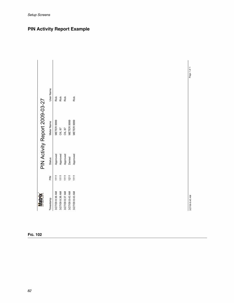
PIN Activity Report Example
FIG. 102
PIN
Act
ivity
Rep
ort 2
009-
03-2
7P
INM
eter
Nam
eU
ser N
ame
Sta
tus
Tim
esta
mp
3/27
/09
8:36
AM
1111
ME
TER
999
9R
ick
App
rove
d
3/27
/09
8:36
AM
1111
OIL
87
Ric
kA
ppro
ved
3/27
/09
8:37
AM
1111
OIL
87
Ric
kA
ppro
ved
3/27
/09
8:43
AM
1211
ME
TER
999
9D
enie
d
3/27
/09
8:43
AM
1111
ME
TER
999
9R
ick
App
rove
d
Pag
e 1
of1
3/27
/09
8:45
AM

Setup Screens
83
• PRA Activity Screen (FIG. 103)
• Report Name: Assigned name given to the report. This name will appear on the top of the report• Output Format - PDF/CSV: Type of format for file that will be generated when you select RUN
REPORT button• Date Range - Start/End (or choose range): Specifies beginning and end dates covered by the
report. Available, predefined, range choices include:
✓ Today✓ Yesterday✓ Last 5 days✓ Last 7 days✓ Last 30 days✓ Month to date✓ Year to date
• Run Report Button: Generates report in output file format
FIG. 103

Setup Screens
84
PRA Activity Report Example
FIG. 104
PRA Activity Report 2009-03-27Timestamp Request Status Meter Name
3/27/09 8:38 AM Approved METER 53
3/27/09 8:40 AM Approved METER 53
3/27/09 8:41 AM Denied METER 53
3/27/09 8:41 AM Approved METER 53
3/27/09 8:41 AM Approved METER 51
Page 1 of 13/27/09 8:50 AM

Setup Screens
85
• Current Tank Volumes (FIG. 105)
• Report Name: Assigned name given to the report. This name will appear on the top of the report• Output Format - PDF/CSV: Type of format for file that will be generated when you select RUN
REPORT button• Sort Order - Available Fields: The order available fields are sorted in the report• Up or Down Buttons: Shifts highlight field for sort order Up/Down• Run Report Button: Generates report in output file format
FIG. 105
Setup Screens
86
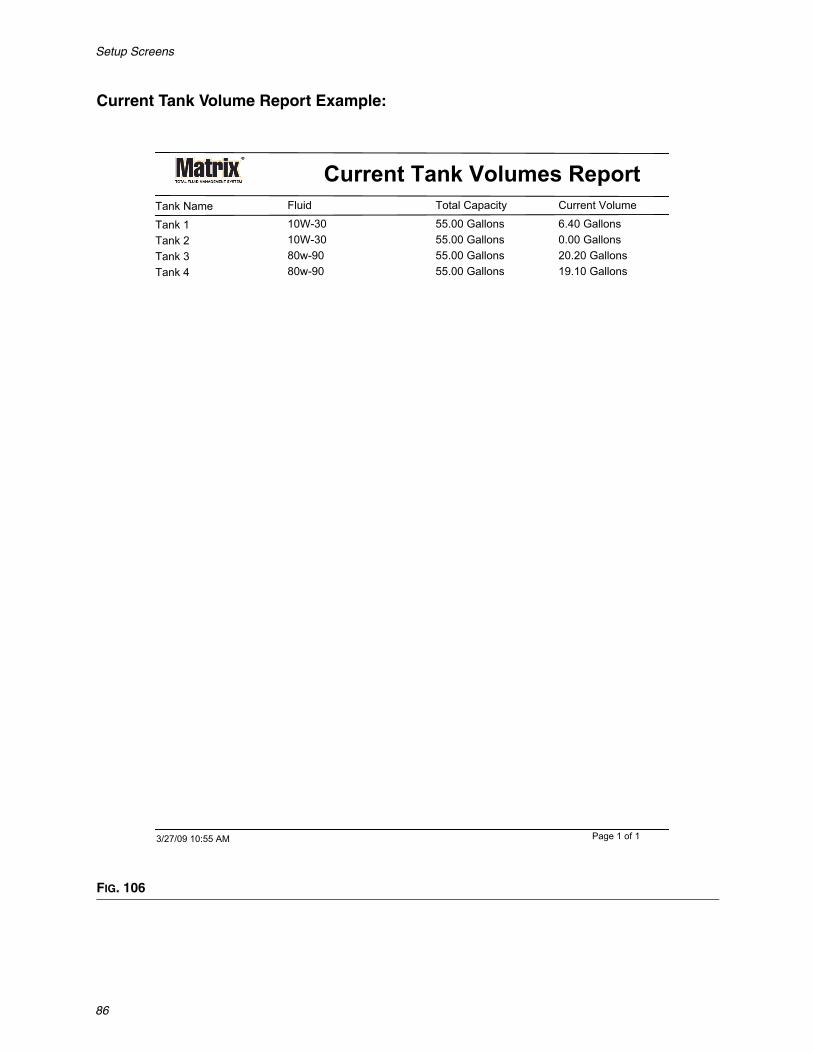
Current Tank Volume Report Example:
FIG. 106
Current Tank Volumes ReportTank Name Total Capacity Current VolumeFluid
Tank 1 55.00 Gallons 6.40 Gallons10W-30Tank 2 55.00 Gallons 0.00 Gallons10W-30Tank 3 55.00 Gallons 20.20 Gallons80w-90Tank 4 55.00 Gallons 19.10 Gallons80w-90
Page 1 of 13/27/09 10:55 AM
Setup Screens
87
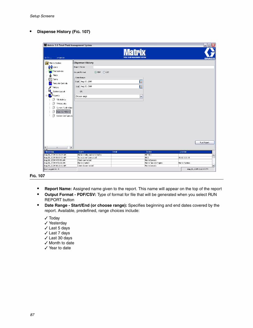
• Dispense History (FIG. 107)
• Report Name: Assigned name given to the report. This name will appear on the top of the report• Output Format - PDF/CSV: Type of format for file that will be generated when you select RUN
REPORT button• Date Range - Start/End (or choose range): Specifies beginning and end dates covered by the
report. Available, predefined, range choices include:
✓ Today✓ Yesterday✓ Last 5 days✓ Last 7 days✓ Last 30 days✓ Month to date✓ Year to date
FIG. 107

Setup Screens
88
Dispense History Report Example:
FIG. 108
Dispense History Report 2009-08-20Report Date: 8/20/09 2:24 PM
Timestamp Amount Fluid Work OrderMeter Name Job CodeAug 17, 2009 5:21:02 PM 2.44 Quarts 20W-40 546METER 2
Aug 17, 2009 5:20:47 PM 2.39 Quarts 20W-40 568METER 2
Aug 17, 2009 5:20:33 PM 1.72 Quarts 20W-40 12METER 2
Aug 17, 2009 5:20:17 PM 0.80 Quarts 20W-40 123456METER 2
Aug 17, 2009 5:14:47 PM 1.34 Quarts 20W-40METER 2
Aug 17, 2009 5:14:35 PM 2.33 Quarts 20W-40METER 2
Aug 17, 2009 5:14:27 PM 0.62 Quarts 20W-40METER 2
Aug 17, 2009 5:14:17 PM 1.05 Quarts 20W-40METER 2
Aug 17, 2009 5:14:05 PM 2.68 Quarts 20W-40METER 2
Aug 17, 2009 5:13:53 PM 1.56 Quarts 20W-40METER 2
Aug 17, 2009 5:13:40 PM 2.15 Quarts 20W-40METER 2
Aug 17, 2009 5:13:36 PM 0.35 Quarts 20W-40METER 2
Aug 17, 2009 5:13:28 PM 1.15 Quarts 20W-40METER 2
Page 1 of 18/20/09 2:24 PM

Setup Screens
89
• System Configuration (FIG. 109)
• Output Format - PDF or CSV: Type of format for file that will be generated when you select RUN REPORT button
• Include all Setup Parameters Checkbox: Generates all setup parameters when the report is run• Setup Report Content (Fluid, Tanks, Pump Air Controls, Meters, Users, and System Parame-
ters check boxes): Selects specific setup parameters to be generated in the report• Run Report button: Generates report in output file format
FIG. 109

Setup Screens
90
System Configuration Report Example:
FIG. 110
Syst
em C
onfig
urat
ion
Rep
ort
Flui
dsFl
uid
Nam
eFl
uid
Type
10W
-30
Oil/
ATF
80w
-90
Gea
r Lub
eA
ntiF
reez
eA
nti-F
reez
e 50
/50
Tank
sTa
nk N
ame
Tank
Sha
peLe
ngth
Wid
thFl
uid
War
ning
Leve
lFl
uid
War
ning
Flui
d N
ame
Dev
ice
Gro
up
Cap
acity
(Cyl
inde
r &O
brou
nd)
(Obr
ound
)
Tank
1V
ertic
al0
IN0
IN10
L10
W-3
0
Bay
1
55.0
0 G
L
Tank
2V
ertic
al0
IN0
IN10
L10
W-3
0
Bay
2
55.0
0 G
L
Tank
3V
ertic
al0
IN0
IN10
L80
w-9
0
Bay
3
55.0
0 G
L
Tank
4V
ertic
al0
IN0
IN10
L80
w-9
0
Bay
4
55.0
0 G
L
Tank
Lev
el M
onito
rs
Pag
e 1
of6
3/27
/09
11:0
0 A
M

Work Orders
91
SECTION
6
Work Orders
Work Orders
92
Work Orders
Work Orders and Job CodesThe System Administrator can setup the meter profile to process work orders using one of the following:
• Work Order/Job Code at the PC only• Work Order/Job Code at the PC and Meter • Global Work Orders
Work Orders can have a maximum of (8) characters. The Job Code can have a maximum of (3) characters. The Work Order number is separated from the Job Code with a dash (-).
The numbers, 0 - 9; alphabet characters, A - Z; and period (.), forward slash (/) and dash (-) or space characters can be used when assigning a Work Order or Job Number. One Work Order can require more than one service.
Note: One naming convention that can be implemented for identifying different services on a Work Order is adding an extension to the end of the order number (i.e., 123456-oil, 123456-ATF).
The meter can receive any number of work orders. New work orders added at the PC will appear at the end of the work order list. This is known as the First In - First Out Method.
On the meter, the UP or DOWN ARROWS are used to scroll through the list of entered work orders.
Work orders entered at the meter appear at the beginning of the Work Order list on the meter and are placed ahead of Work Orders previously entered on the PC.
Assigning Work Orders and Job Codes from the PC
Work Orders and Job Codes can be assigned to a meter from the PC using the “Work Order Queue” in the software. This feature is password protected.
• The System Default for Use Global Workorder (page 37), must be set to NO.
• On the Meter Setup screen (page 70), Use Work Orders and Work Order Entry at Meter must be set to YES.
In the System Administrator Defined Groups area of the Matrix Main Screen (A), select the meter you are sending the Work Order to (FIG. 111).

Work Orders
93
2. In the Work Order Queue section (B) of the screen click the Add button (C) and in the pop-up box (D) type in your User name and Password. Click OK.
3. On the Add Work Order screen, enter:
• Work Order and Job Code numbers - See Work Orders and Job Codes on page 92 for field requirements.
• Preset amount -- amount of fluid and the way it is measured associated with work order.
FIG. 111
FIG. 112
FIG. 113
A
CD

Work Orders
94
4. Click OK to add the work order to the Work Order Queue. A new line appears in the Work Order Queue area of the screen.
Entering a Global Work Order
You must have a System Administrator or Global Work order privileges to access the Global Work Order creation screens and Global Workorders must be set to YES on the System Default setup screen, page 37.
1. Select the Global Work Orders tab (FIG. 114).
2. Click the Add button to enter a new work order in the system.
3. The popup box shown in FIG. 115 appears for you to provide a User Name and Password.
4. The Add Work Order popup screen is shown in FIG. 116.
Work Order Number
FIG. 114
FIG. 115
FIG. 116

Work Orders
95
This screen is used to enter:
• Fluid - type of fluid you will dispense.
• Group - (optional selection). Defaults to Matrix System. If you choose a group instead, only the meters in that specific group will be able to select that work order.
• Work Order Number and Job Code - Work Orders can have a maximum of (8) characters and The Job Code can have a maximum of (3) characters. The meter can receive any number of work orders and Job Code Numbers. The Work Order number is separated from the Job Code with a dash (-). The numbers, 0 - 9; alphabet characters, A - Z; and period (.), forward slash (/) and dash (-) or space char-acters can be used when assigning a Work Order or Job Number. One Work Order can require more than one service.
• Preset amount - amount associated with work order.
• Units of Measure - English (Gallons, Quarts or Pints) or Metric (Liter) measurement value.
Click OK to add the work order to the Global Work Order Queue.
Adding Global Work Orders to the Meter
1. In the System Administrator Defined Groups area of the Matrix Main Screen (A), select the meter you are sending the Work Order to (FIG. 117).
2. In the Work Order Queue section (B) of the screen click the Add button (C) (FIG. 117). A list of work orders available to that meter displays.
NOTE: A meter will only display global work orders whose fluid and group assignments match the meter’s defined parameters.
FIG. 117
A
B
C
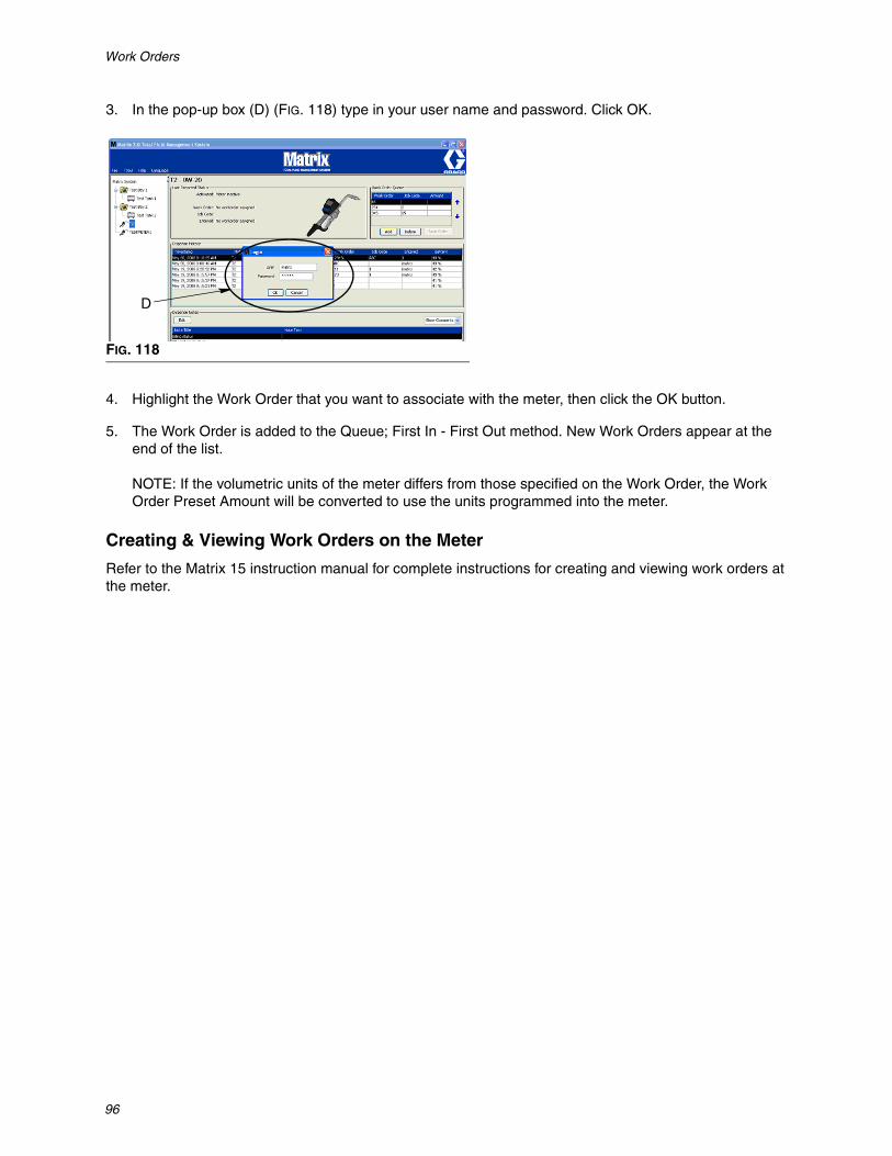
Work Orders
96
3. In the pop-up box (D) (FIG. 118) type in your user name and password. Click OK.
4. Highlight the Work Order that you want to associate with the meter, then click the OK button.
5. The Work Order is added to the Queue; First In - First Out method. New Work Orders appear at the end of the list.
NOTE: If the volumetric units of the meter differs from those specified on the Work Order, the Work Order Preset Amount will be converted to use the units programmed into the meter.
Creating & Viewing Work Orders on the Meter
Refer to the Matrix 15 instruction manual for complete instructions for creating and viewing work orders at the meter.
FIG. 118
D

Frequently Asked Questions (FAQ)
97
SECTION
7
Frequently Asked Questions (FAQ)
Frequently Asked Questions (FAQ)
98
Matrix 3 FAQ
1. Q. When using the “Balanced” or “Power Saving” power plans in Vista, the default setting before the PC goes to sleep, shuts down the USB ports, and the meters show “No PC Sig-nal”, is 1 hour.
A. This condition is known as the Hibernation Mode. Matrix 3 cannot run efficiently on a sys-tem when this feature is enabled. There are two setup screens that must be changed to stop the PC from going into the Hibernation Mode:
• The first is to set the “Computer to Sleep” option to NEVER. • The second change is located is under “Advanced Settings”.• Instructions for changing these default settings are provided in the Installation Instructions, the
Hibernation Mode section, beginning on page 21.
2. Q. An error message popped up when I was installing the Silicon Labs drivers on a Matrix 3 system.
A. This error happens if you have Symantec Endpoint Protection (SEP) software. If you know you have SEP, try to disable it or turn it off for the duration of the Matrix Setup process.
To proceed with the Matrix 3 software installation:
If you are NOT able to disable SEP -
a. When you get to the point of installing the Matrix transceiver drivers, click NEXT to proceed as you ordinarily would. The driver installation file will attempt to run; it will fail and a message from Win-dows will appear asking if you want to send an error report to Microsoft.
b. Click “Don’t Send” and complete the Matrix installation.
c. When installation is finished, reboot the PC.
d. As the PC begins to start up again, press the F8 key to access the Windows startup menu options.
e. Choose “Safe Mode with Networking”. This will launch Windows without enabling SEP. You proba-bly will have to acknowledge one or two dialogs that Windows will pop up as it loads.
f. Once Windows is running in safe mode, open Windows Explorer and navigate to the Matrix instal-lation directory (default is “C:\Program Files\Graco\Matrix3”. In the “C:\Program Files\Graco\Matrix3\XcvrServer\vcp” folder, double click on the CP210xVCPInstaller.exe file to manually run the driver installer.
g. When the driver installer completes, shut down Windows and restart in the normal way. Matrix should detect any Graco transceivers or RS422 converters when powered up and plugged into the USB bus.
If you are able to disable SEP -
a. Disable SEP before beginning Matrix installation and install Matrix as normal.
b. When complete, enable SEP before rebooting the PC.

Frequently Asked Questions (FAQ)
99
3. Q. What does the meter do if the batteries are removed when you are dispensing?
A. If you aren't using workorders, the accumulated dispense amount is saved. When fresh batteries are inserted, the meter powers up in its start screen (PIN, PRA or Start Dispense). The next time a dis-pense ends, two entries show up in the PC's dispense complete log---the accumulated amount from the first dispense and the dispense just completed. If the meter is in workorder mode, when batteries are reinserted the meter returns to an end dispense screen with no active trigger and the dispense amount displayed----the dispense must be ended before another can be started.
4. Q. What does the meter do if a low battery condition occurs during a dispense?
A.The trigger is disengaged and the low battery symbol appears on the meter display. If the meter is allowed to fall asleep in this low battery mode, an attempt will be made to end the dispense. If the attempt is not successful, when fresh batteries are reinserted, the meter returns to an end dispense screen and an end must occur before another dispense can happen. If the meter is not using workorders, the accumulated dispense value is saved and is sent to the PC at the next successful end of dispense.
5. Q. When I launch the Matrix Client by double-clicking the icon on the desktop, nothing comes up and no error message is displayed.
A. If you don't have enough system memory, this will happen not only for the Matrix Client PC, but also for the Matrix Server. Make sure you meet the computer memory (RAM) specifications as defined in the software user manual.
6. Q. When I launch the Matrix Client after starting up my PC, I get a message that says "Unable to send message to MSE".
A.The Matrix Client software must be able to connect to the Matrix Server when it starts up. If for any reason it cannot, it'll display this message. You may find that sometimes it will run by simply dou-ble-clicking the icon again, because the Server was given a bit more time to get running.
7. Q. Unplugging or powering down the Transceiver will cause communication over the device to stop immediately. How is this communication reestablished?
A. Graco recommends unplugging the transceiver’s USB cable or power cable. Then pause for approx-imately 5 seconds before plugging it back in again. Transceiver setup instructions are provided on page 55.
Frequently Asked Questions (FAQ)
100
8. Q. Why did my Work Order disappear from the Work Order Queue?
A. The meter might have received a new profile. After the meter receives a new profile the Work Order Queue is cleaned out.
9. Q. Why does the Matrix Client say “Unable to send message to MSE” when I change my Hostname from “localhost” to the PC name or IP address?
A. The PC name can only have ASCII characters a-z, 0-9, and hyphen. The hyphen can’t be at the beginning or end or the PC name.
10. Q. When I am changing the system layout and click OK, why do I get the following messages?
Unable to save object(s) and the message from the Matrix Service Engine: An error occurred while processing request.
A. User should not make modification to the system layout when system is in use. Only make modifica-tions when there are no active dispenses.
11. Problem: Symantic Endpoint Protection (SEP) is interfering with Matrix setup. Error Code: 3177
Solution A:
a. Try to disable SEP or turn it off for the duration of the Matrix setup process.
b. Then install Matrix as normal.
c. When complete, enable SEP before rebooting Computer.
Solution B: If you cannot disable SEP:
a. When you get to the point of installing the Matrix Transceiver drivers, click Next to proceed as you usually would. The driver installation file will attempt to run. It will fail.
b. A message from Windows will appear asking if you want to send an error report to Microsoft. Click Don’t Send and complete the Matrix installation.
c. When finished, Reboot the PC.
d. As the PC begins to start up again, press the F8 key to access the Windows setup menu options.
e. Choose “Safe Mode with Networking”. This will launch Windows without enabling SEP.
Note: You will probably have to acknowledge one or two dialogs that Windows will pop up as it loads.
f. With Windows running in Safe Mode, open Windows Explorer and navigate to the Matrix Installa-tion Directory. (Default is: “C:\Program Files\Graco\Matrix3”).
g. In the “C:\Program Files\Graco\Matrix3\XcvrServer\vcp” folder, double click on the CP210xVCPInstaller.exe file to manually run the driver installer.
Frequently Asked Questions (FAQ)
101
h. When the driver installer completes, shut down Windows and restart in the normal way. Matrix should detect any Graco Transceivers or RS422 converters when powered up and plugged into the USB bus.
12. Q. How do you set up the date range on the Dispense History Report screen? Error Code 3138
A. There are two ways to setup the date range on the Dispense History Report screen.
• One way is to select a fixed date from the drop-down box.• The other way is to select one of the following options from the drop-down box:
Choose RangeTodayYesterdayLast 5 DaysLast 7 DaysLast 30 DaysMonth to DateYear to Date
If the Choose Range option is selected, the date range in effect is defined by the start and end dates. If any other selection is chosen, the start and end dates are ignored and the selected item from the drop-down box defines the date range.
13. Problem: When Matrix service starts up, it cannot connect. Error Code 2988.
Solution: One of the first things that Matrix does when it first starts up is try to connect to the data base service. If it cannot connect, it will pause 10 seconds and try again. If after 5 attempts it still hasn’t been able to connect to the data base service, it will stop trying and quit.
14. Problem: When the user double-clicks on the Client icon, the Client will not start up. Error Code 3034.
Solution: Either the MSE is not running or running, but still trying to connect to the database.
The popup message that says “Cannot connect to the MSE” is generated. When you click OK to this message, the Client will exit and not run again unless the user double-clicks on the icon again.
This is actually normal if you try running the Client immediately after Windows boots up. Usually, it takes a little while for the database service and the MSE service to fully start when a PC boots up. Graco recommends allowing about 30 seconds after the desktop first appears, for Windows to finish starting up before launching the Matrix Client.
However, if the database is not running, the MSE will also not run. Reasons for the database to not be running include: the PC that Matrix is installed on is not running or is not on the network, or the data-base may be corrupted due to an abrupt power outage.
When this happens, the user is not shown an error message of any kind. The failure the user will see occurs when the user attempt to run the Client. At this time they will receive a message that says “Can-not connect o MSE”.
A user who has Administrative privileges on the local machine can manually start by going to the Ser-vice Screen in Windows using the following procedure:
a. Right click on My Computer b. Selecting Managec. Double click on Services and Applications

Frequently Asked Questions (FAQ)
102
d. Double click on Services
If the user doesn’t have Administrative privileges on the local machine, they will have to reboot the computer. They will not be able to access the Service Screen to start or restart a service.
Finally, if the system was not properly configured they will also receive an error message. For example, when installing the client software on a client PC, the setup program prompts for the host name of the machine running the MSE and the database (often, these will be one on the same machine). If the cli-ent isn’t “pointing” at the right machine, it will give the “Can’t connect to MSE” message.
To check that the correct host name and data base were setup, run the Matrix Properties File Editor.
a. Click on Start/All Programs/Graco/Matrix3/Utilities/Edit Matrix Settings.
b. Verify that the Matrix Database Server host name and Matrix Server (MSE) host name are set to the correct host name and that server’s firewall (if it has one) isn’t blocking the ports listed in this utility. If there are errors, correct them.
15. Problem: The per-dispense printer drop-down box on the Matrix System/System Defaults setup page reflect the printers available on the machine running the MSE, NOT the Client. Error Code 2982.
Solution: The MSE service be be configured by a user with Administrative privileges. To modify the MSE:
a. Right click on My Computer b. Selecting Managec. Double click on Services and Applicationsd. Double click on Services e. Select Properties.f. Select the Log On tab.g. Select “This account” and provide the account name and password that exists on that machine.h. Apply the changes and restart the service.
The MSE will now run as if that user had started it. The per-dispense printer list will show the printers that are available to the selected user on this machine.
16. Problem: I cannot see all of the information and buttons on the Matrix screen and it looks distorted or out of proportion. Error Code 2915.
Solution: Check the font size setting you are using for your Windows application. Matrix cannot accommodate using larger fonts.
a. Right click anywhere on the desktop. b. Choose Properties from the pop-up box.c. Click on the Appearance Tab. d. From the drop-down Font Size box, select Normal.e. Click the Apply and OK buttons to close the screen.

Appendix A
103
SECTION
8
Appendix A

Appendix A
104
How to find a PC’s host name in Windows XP1. The PC’s computer name (also known as the Host Name) is found on the System Properties screen.
To display this screen, on the Windows Desktop click Start/Control Panel (FIG. 119).
2. The Control Panel is shown in FIG. 120.
• Double click on the System Icon.
FIG. 119
FIG. 120

Appendix A
105
3. Click the Computer Name tab.
In the example shown in FIG. 121, the Full Computer Name is PC8868.msp.graco.com.
FIG. 121

Appendix A
106
How to find a PC’s host name in Windows Vista1. The PC’s computer name (also known as the Host Name) is found on the System Properties screen.
To display this screen, on the Windows Desktop click Start/Control Panel (FIG. 122).
2. Double click on the System Icon (FIG. 123).
In the example shown in FIG. 124, the Computer Name is vista1.
FIG. 122
FIG. 123
FIG. 124
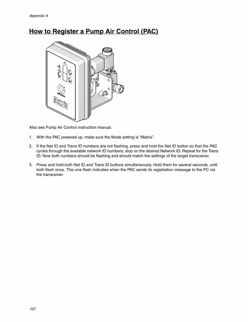
Appendix A
107
How to Register a Pump Air Control (PAC)
Also see Pump Air Control instruction manual.
1. With the PAC powered up, make sure the Mode setting is “Matrix”.
2. If the Net ID and Trans ID numbers are not flashing, press and hold the Net ID button so that the PAC cycles through the available network ID numbers; stop on the desired Network ID. Repeat for the Trans ID. Now both numbers should be flashing and should match the settings of the target transceiver.
3. Press and hold both Net ID and Trans ID buttons simultaneously. Hold them for several seconds, until both flash once. This one flash indicates when the PAC sends its registration message to the PC via the transceiver.
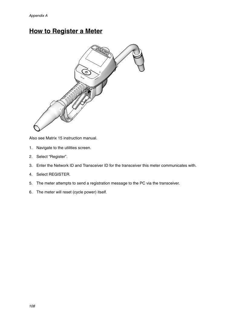
Appendix A
108
How to Register a Meter
Also see Matrix 15 instruction manual.
1. Navigate to the utilities screen.
2. Select “Register”.
3. Enter the Network ID and Transceiver ID for the transceiver this meter communicates with.
4. Select REGISTER.
5. The meter attempts to send a registration message to the PC via the transceiver.
6. The meter will reset (cycle power) itself.

Appendix A
109
Matrix Properties File Editor
Exporting/Importing Matrix3 Database
Export - to export a Matrix3 Database click File->Database Utilities -> Export. The user will be prompted for User Name and Password. The default filename will be:
• manualBackup_20081010_103749.sql• 20081010 corresponds to the date 10/10/2008 and the 103749 corresponds to the time 10:37 AM
and 49 seconds
Import - to import a Matrix3 Database click File->Database Utilities->Import. User will be prompted for User Name and Password.
NOTE: File being imported must have been created from the same software version of Matrix that is installed on the PC. Existing databases will be completely replaced.
File Editor
Database Export File Directory: Default location in Microsoft® Windows where the Matrix Database file will be exported and saved.
Matrix Client Name: A name unique to this Matrix Client. Although using the PC’s host name (or IP address) can be used and is often convenient for this purpose, it can be any name.
Matrix Client Port: The Matrix Client application listens on this port for messages pushed to it from the Matrix Service Engine (MSE). (*Default: 20002)
Matrix Database Server Host Name: This is the host name or IP address of the PC running the Matrix Database. In a single PC system this can be labeled localhost.
Matrix Database Port: The port number that the database server listens on for requests (*Default: 20006)
Matrix Server (MSE) Host Name: This is the host name or IP address of the PC running the Matrix Ser-vice Engine (MSE), sometimes referred to as the “MatrixServer”. In a single PC system this can be labeled localhost.
Matrix Server (MSE) Port: The port number that the MSE listens on for requests from other system com-ponents, such as the Matrix Client and the Matrix Transceiver Server (*Default: 20000)

Appendix A
110
Matrix Server (MSE) Port, Monitor: Used by Graco Tech Assistance personnel only. This port is used for debugging purposes. (*Default: 20001)
Operating Screen Refresh Interval (Seconds): Matrix Client operating screens will do a complete screen refresh at this interval, specified in seconds. The allowable range is 20 to 1,000,000 seconds (Default: 300 seconds).
Report Output Directory: Default location in Microsoft Windows where Reports will be saved when the user generates a report.
Transceiver Client Port: The port number the Matrix Transceiver Server (on this PC) listens on. (*Default: 20003)
Transceiver Server Port, Monitor: For use by Graco Tech Assistance personnel only. This port is used for debugging purposes. (*Default: 20004)
*Numbers 20000 - 49151 are available. Refer to Internet Assigned Numbers Authority (IANA) port list for reference or conflicting ports.

Notes
111
Notes

All written and visual data contained in this document reflects the latest product information available at the time of publication. Graco reserves the right to make changes at any time without notice.
For patent information, see www.graco.com/patents.
Original instructions. This manual contains English. MM 313104
Graco Headquarters: MinneapolisInternational Offices: Belgium, China, Japan, Korea
GRACO INC. AND SUBSIDIARIES • P.O. BOX 1441 • MINNEAPOLIS MN 55440-1441 • USA
Copyright 2009, Graco Inc. All Graco manufacturing locations are registered to ISO 9001.www.graco.com
Revised July 2012
Graco Software WarrantyGraco warrants all equipment manufactured by Graco and bearing its name to be free from defects in material and workmanship on the date of sale to the original purchaser for use. With the exception of any special, extended, or limited warranty published by Graco, Graco will, for a period of twenty-four months from the date of sale, repair or replace any part of the equipment determined by Graco to be defective. This warranty applies only when the equipment is installed, operated and maintained in accordance with Graco's written recommendations.
This warranty does not cover, and Graco shall not be liable for general wear and tear, or any malfunction, damage or wear caused by faulty installation, misapplication, abrasion, corrosion, inadequate or improper maintenance, negligence, accident, tampering, or substitution of non-Graco component parts. Nor shall Graco be liable for malfunction, damage or wear caused by the incompatibility of Graco equipment with structures, accessories, equipment or materials not supplied by Graco, or the improper design, manufacture, installation, operation or maintenance of structures, accessories, equipment or materials not supplied by Graco.
This warranty is conditioned upon the prepaid return of the equipment claimed to be defective to an authorized Graco distributor for verification of the claimed defect. If the claimed defect is verified, Graco will repair or replace free of charge any defective parts. The equipment will be returned to the original purchaser transportation prepaid. If inspection of the equipment does not disclose any defect in material or workmanship, repairs will be made at a reasonable charge, which charges may include the costs of parts, labor, and transportation.
THIS WARRANTY IS EXCLUSIVE, AND IS IN LIEU OF ANY OTHER WARRANTIES, EXPRESS OR IMPLIED, INCLUDING BUT NOT LIMITED TO WARRANTY OF MERCHANTABILITY OR WARRANTY OF FITNESS FOR A PARTICULAR PURPOSE.
Graco's sole obligation and buyer's sole remedy for any breach of warranty shall be as set forth above. The buyer agrees that no other remedy (including, but not limited to, incidental or consequential damages for lost profits, lost sales, injury to person or property, or any other incidental or consequential loss) shall be available. Any action for breach of warranty must be brought within two (2) years of the date of sale.
Graco makes no warranty, and disclaims all implied warranties of merchantability and fitness for a particular purpose in connection with accessories, equipment, materials or components sold but not manufactured by Graco. These items sold, but not manufactured by Graco (such as electric motors, switches, hose, etc.), are subject to the warranty, if any, of their manufacturer. Graco will provide purchaser with reasonable assistance in making any claim for breach of these warranties.
In no event will Graco be liable for indirect, incidental, special or consequential damages resulting from Graco supplying equipment hereunder, or the furnishing, performance, or use of any products or other goods sold hereto, whether due to a breach of contract, breach of warranty, the negligence of Graco, or otherwise.
FOR GRACO CANADA CUSTOMERS
The parties acknowledge that they have required that the present document, as well as all documents, notices and legal proceedings entered into, given or instituted pursuant hereto or relating directly or indirectly hereto, be drawn up in English. Les parties reconnaissent avoir convenu que la rédaction du présente document sera en Anglais, ainsi que tous documents, avis et procédures judiciaires exécutés, donnés ou intentés à la suite de ou en rapport, directement ou indirectement, avec les procedures concernées.
Graco InformationTO PLACE AN ORDER, contact your Graco distributor or call to identify the nearest distributor.
Phone: 612-623-6928 or Toll Free: 1-800-533-9655, Fax: 612-378-3590