311511g -reactor a-20 operation, english · 311511g eng operation reactor a-20 air operated,...
TRANSCRIPT

311511GENG
Operation
Reactor A-20Air Operated, Electrically Heated Plural Component ProportionerFor spraying or dispensing 1:1 mix ratio materials, including epoxies and polyurethane foam. For professional use only.
Not approved for use in European explosive atmosphere locations.
See page 3 for a list of models and maximum working pressures.
US Patent No. 7822326Russian Patent No. 2359181
Important Safety InstructionsRead all warnings and instructions in this manual. Save these instructions.
TI8447A
Contents
2 311511G
ContentsRelated Manuals . . . . . . . . . . . . . . . . . . . . . . . . . . . 2Systems . . . . . . . . . . . . . . . . . . . . . . . . . . . . . . . . . . 3Warnings . . . . . . . . . . . . . . . . . . . . . . . . . . . . . . . . . 4Typical Installation, without Circulation . . . . . . . . 7Typical Installation, with Circulation . . . . . . . . . . . 8Moisture Sensitivity of Isocyanates . . . . . . . . . . . . 9
Foam Self-Ignition . . . . . . . . . . . . . . . . . . . . . . . . 9Isocyanate Hazard . . . . . . . . . . . . . . . . . . . . . . . 9Keep Components A and B Separate . . . . . . . . . 9Changing Materials . . . . . . . . . . . . . . . . . . . . . . . 9
Component Identification . . . . . . . . . . . . . . . . . . . 10Controls and Indicators . . . . . . . . . . . . . . . . . . . . 12Pressure Relief Procedure . . . . . . . . . . . . . . . . . . 13Flushing . . . . . . . . . . . . . . . . . . . . . . . . . . . . . . . . . 13Setup . . . . . . . . . . . . . . . . . . . . . . . . . . . . . . . . . . . . 14
Locate Reactor A-20 . . . . . . . . . . . . . . . . . . . . . 14Determine Power Source . . . . . . . . . . . . . . . . . 14Electrical Requirements . . . . . . . . . . . . . . . . . . 14Configure to Supply Power . . . . . . . . . . . . . . . . 15Ground System . . . . . . . . . . . . . . . . . . . . . . . . . 17Iso Pump Lubrication System Setup . . . . . . . . . 17Fluid Supply Connections . . . . . . . . . . . . . . . . . 17Air Supply Connection . . . . . . . . . . . . . . . . . . . 17Connect FTS and Heated Dual Whip Hose . . . 18Recirculation / Pressure Relief Lines . . . . . . . . 19Connect Heated Hose . . . . . . . . . . . . . . . . . . . . 19Close Gun Fluid Manifold Valves A and B . . . . . 20Connect Whip Hose to Gun Fluid Manifold . . . . 20Pressure Check Hose . . . . . . . . . . . . . . . . . . . . 20
Initial Startup . . . . . . . . . . . . . . . . . . . . . . . . . . . . . 21Fluid Temperature Sensor (FTS) Calibration . . . 21Load Fluid with Feed Pumps . . . . . . . . . . . . . . . 21Digital Temperature Controllers . . . . . . . . . . . . . 22Over Temperature Alarms . . . . . . . . . . . . . . . . . 24Fluid Heater Temperature Offset . . . . . . . . . . . . 24Hose Heat Manual Mode . . . . . . . . . . . . . . . . . . 24Supply Wet-Cups with Throat Seal Liquid . . . . . 25
Spraying Setup . . . . . . . . . . . . . . . . . . . . . . . . . . . . 26Spray Adjustments . . . . . . . . . . . . . . . . . . . . . . 27
Shutdown . . . . . . . . . . . . . . . . . . . . . . . . . . . . . . . . 28Operation . . . . . . . . . . . . . . . . . . . . . . . . . . . . . . . . 29
Daily Start-up Procedure . . . . . . . . . . . . . . . . . . 29Fluid Circulation . . . . . . . . . . . . . . . . . . . . . . . . . . . 31
Circulation Through Reactor . . . . . . . . . . . . . . . 31Circulation Through Gun Manifold . . . . . . . . . . . 32Maintenance . . . . . . . . . . . . . . . . . . . . . . . . . . . 33
Technical Data . . . . . . . . . . . . . . . . . . . . . . . . . . . . 34Graco Standard Warranty . . . . . . . . . . . . . . . . . . . 36Graco Information . . . . . . . . . . . . . . . . . . . . . . . . . 36
Related ManualsReactor A-20 Repair/Parts Manual 311512
Systems
311511G 3
Systems
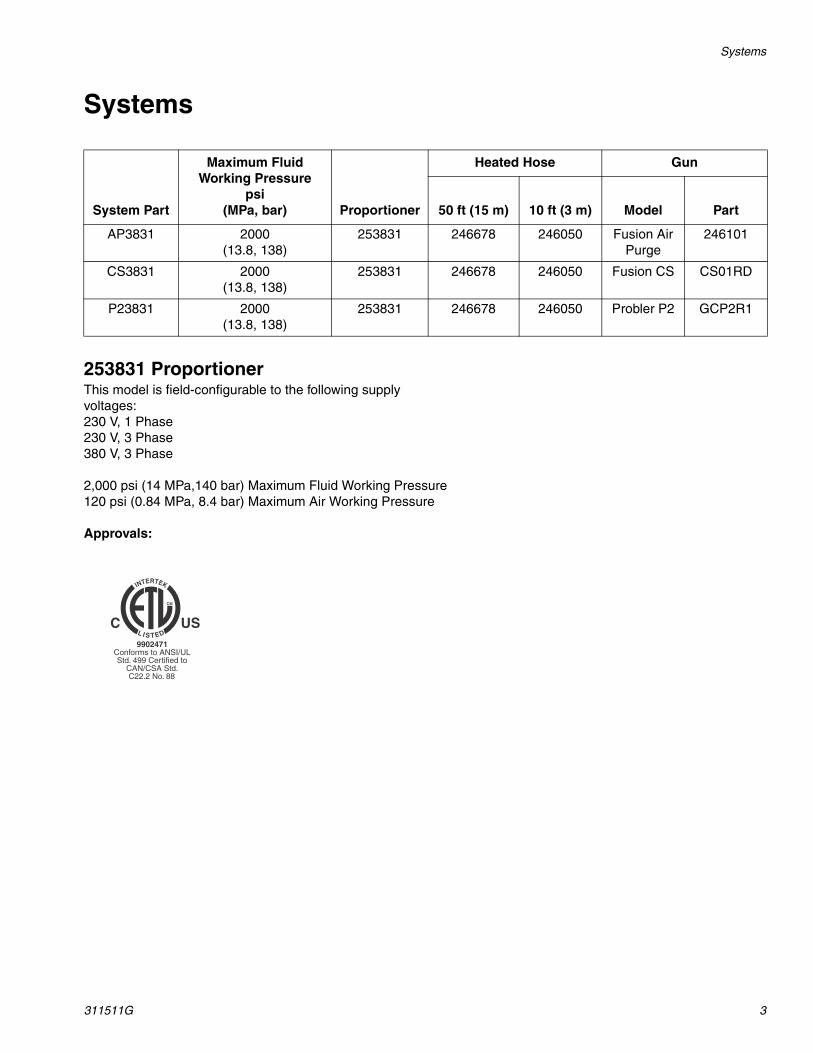
253831 ProportionerThis model is field-configurable to the following supply voltages:230 V, 1 Phase230 V, 3 Phase380 V, 3 Phase
2,000 psi (14 MPa,140 bar) Maximum Fluid Working Pressure120 psi (0.84 MPa, 8.4 bar) Maximum Air Working Pressure
Approvals:
System Part
Maximum Fluid Working Pressure
psi (MPa, bar) Proportioner
Heated Hose Gun
50 ft (15 m) 10 ft (3 m) Model Part
AP3831 2000(13.8, 138)
253831 246678 246050 Fusion Air Purge
246101
CS3831 2000(13.8, 138)
253831 246678 246050 Fusion CS CS01RD
P23831 2000(13.8, 138)
253831 246678 246050 Probler P2 GCP2R1
Warnings
4 311511G
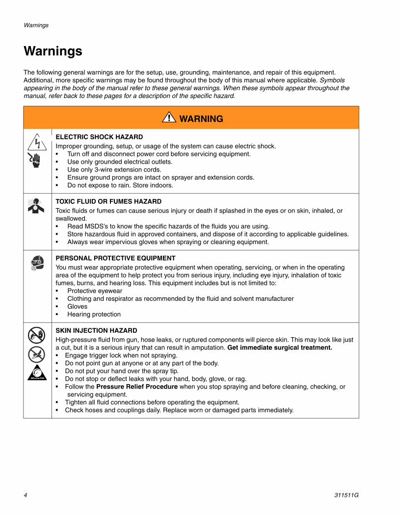
WarningsThe following general warnings are for the setup, use, grounding, maintenance, and repair of this equipment. Additional, more specific warnings may be found throughout the body of this manual where applicable. Symbols appearing in the body of the manual refer to these general warnings. When these symbols appear throughout the manual, refer back to these pages for a description of the specific hazard.
WARNING
ELECTRIC SHOCK HAZARD Improper grounding, setup, or usage of the system can cause electric shock.• Turn off and disconnect power cord before servicing equipment.• Use only grounded electrical outlets.• Use only 3-wire extension cords.• Ensure ground prongs are intact on sprayer and extension cords.• Do not expose to rain. Store indoors.
TOXIC FLUID OR FUMES HAZARD Toxic fluids or fumes can cause serious injury or death if splashed in the eyes or on skin, inhaled, or swallowed.• Read MSDS’s to know the specific hazards of the fluids you are using.• Store hazardous fluid in approved containers, and dispose of it according to applicable guidelines.• Always wear impervious gloves when spraying or cleaning equipment.
PERSONAL PROTECTIVE EQUIPMENT You must wear appropriate protective equipment when operating, servicing, or when in the operating area of the equipment to help protect you from serious injury, including eye injury, inhalation of toxic fumes, burns, and hearing loss. This equipment includes but is not limited to:• Protective eyewear • Clothing and respirator as recommended by the fluid and solvent manufacturer• Gloves• Hearing protection
SKIN INJECTION HAZARD High-pressure fluid from gun, hose leaks, or ruptured components will pierce skin. This may look like just a cut, but it is a serious injury that can result in amputation. Get immediate surgical treatment.• Engage trigger lock when not spraying.• Do not point gun at anyone or at any part of the body.• Do not put your hand over the spray tip.• Do not stop or deflect leaks with your hand, body, glove, or rag.• Follow the Pressure Relief Procedure when you stop spraying and before cleaning, checking, or
servicing equipment. • Tighten all fluid connections before operating the equipment.• Check hoses and couplings daily. Replace worn or damaged parts immediately.
Warnings
311511G 5
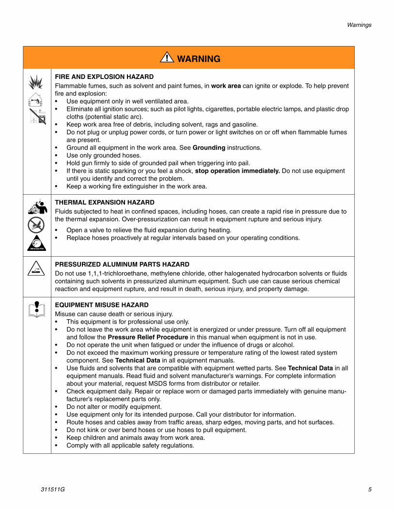
FIRE AND EXPLOSION HAZARD Flammable fumes, such as solvent and paint fumes, in work area can ignite or explode. To help prevent fire and explosion:• Use equipment only in well ventilated area.• Eliminate all ignition sources; such as pilot lights, cigarettes, portable electric lamps, and plastic drop
cloths (potential static arc). • Keep work area free of debris, including solvent, rags and gasoline.• Do not plug or unplug power cords, or turn power or light switches on or off when flammable fumes
are present.• Ground all equipment in the work area. See Grounding instructions.• Use only grounded hoses.• Hold gun firmly to side of grounded pail when triggering into pail.• If there is static sparking or you feel a shock, stop operation immediately. Do not use equipment
until you identify and correct the problem.• Keep a working fire extinguisher in the work area.
THERMAL EXPANSION HAZARD Fluids subjected to heat in confined spaces, including hoses, can create a rapid rise in pressure due to the thermal expansion. Over-pressurization can result in equipment rupture and serious injury.
• Open a valve to relieve the fluid expansion during heating.• Replace hoses proactively at regular intervals based on your operating conditions.
PRESSURIZED ALUMINUM PARTS HAZARD Do not use 1,1,1-trichloroethane, methylene chloride, other halogenated hydrocarbon solvents or fluids containing such solvents in pressurized aluminum equipment. Such use can cause serious chemical reaction and equipment rupture, and result in death, serious injury, and property damage.
EQUIPMENT MISUSE HAZARD Misuse can cause death or serious injury.• This equipment is for professional use only.• Do not leave the work area while equipment is energized or under pressure. Turn off all equipment
and follow the Pressure Relief Procedure in this manual when equipment is not in use.• Do not operate the unit when fatigued or under the influence of drugs or alcohol.• Do not exceed the maximum working pressure or temperature rating of the lowest rated system
component. See Technical Data in all equipment manuals.• Use fluids and solvents that are compatible with equipment wetted parts. See Technical Data in all
equipment manuals. Read fluid and solvent manufacturer’s warnings. For complete information about your material, request MSDS forms from distributor or retailer.
• Check equipment daily. Repair or replace worn or damaged parts immediately with genuine manu-facturer’s replacement parts only.
• Do not alter or modify equipment.• Use equipment only for its intended purpose. Call your distributor for information.• Route hoses and cables away from traffic areas, sharp edges, moving parts, and hot surfaces.• Do not kink or over bend hoses or use hoses to pull equipment.• Keep children and animals away from work area.• Comply with all applicable safety regulations.
WARNING
Warnings
6 311511G
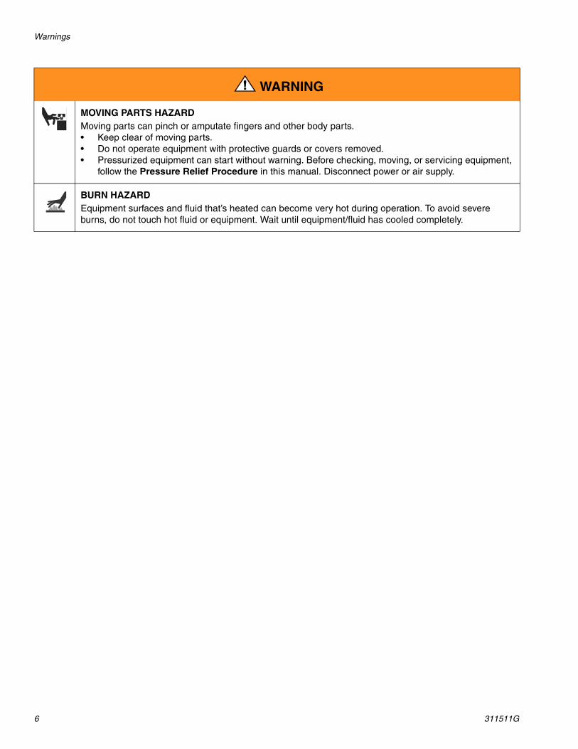
MOVING PARTS HAZARD Moving parts can pinch or amputate fingers and other body parts.• Keep clear of moving parts.• Do not operate equipment with protective guards or covers removed.• Pressurized equipment can start without warning. Before checking, moving, or servicing equipment,
follow the Pressure Relief Procedure in this manual. Disconnect power or air supply.
BURN HAZARD Equipment surfaces and fluid that’s heated can become very hot during operation. To avoid severe burns, do not touch hot fluid or equipment. Wait until equipment/fluid has cooled completely.
WARNING
Typical Installation, without Circulation
311511G 7
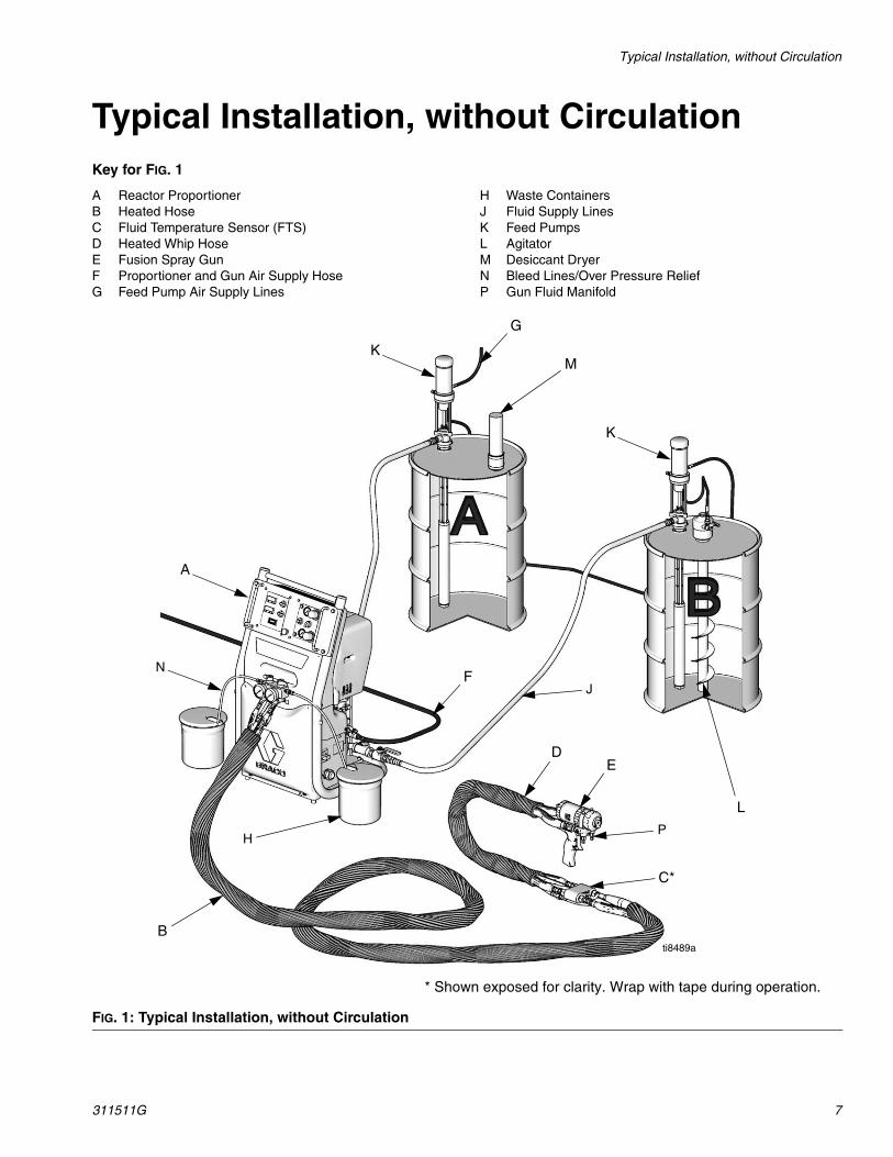
Typical Installation, without CirculationKey for FIG. 1
A Reactor ProportionerB Heated HoseC Fluid Temperature Sensor (FTS)D Heated Whip HoseE Fusion Spray GunF Proportioner and Gun Air Supply HoseG Feed Pump Air Supply Lines
H Waste ContainersJ Fluid Supply LinesK Feed PumpsL AgitatorM Desiccant DryerN Bleed Lines/Over Pressure ReliefP Gun Fluid Manifold
FIG. 1: Typical Installation, without Circulation
A
B
C*
DE
K
L
M
F
P
N
* Shown exposed for clarity. Wrap with tape during operation.
K
H
J
G
ti8489a
Typical Installation, with Circulation
8 311511G
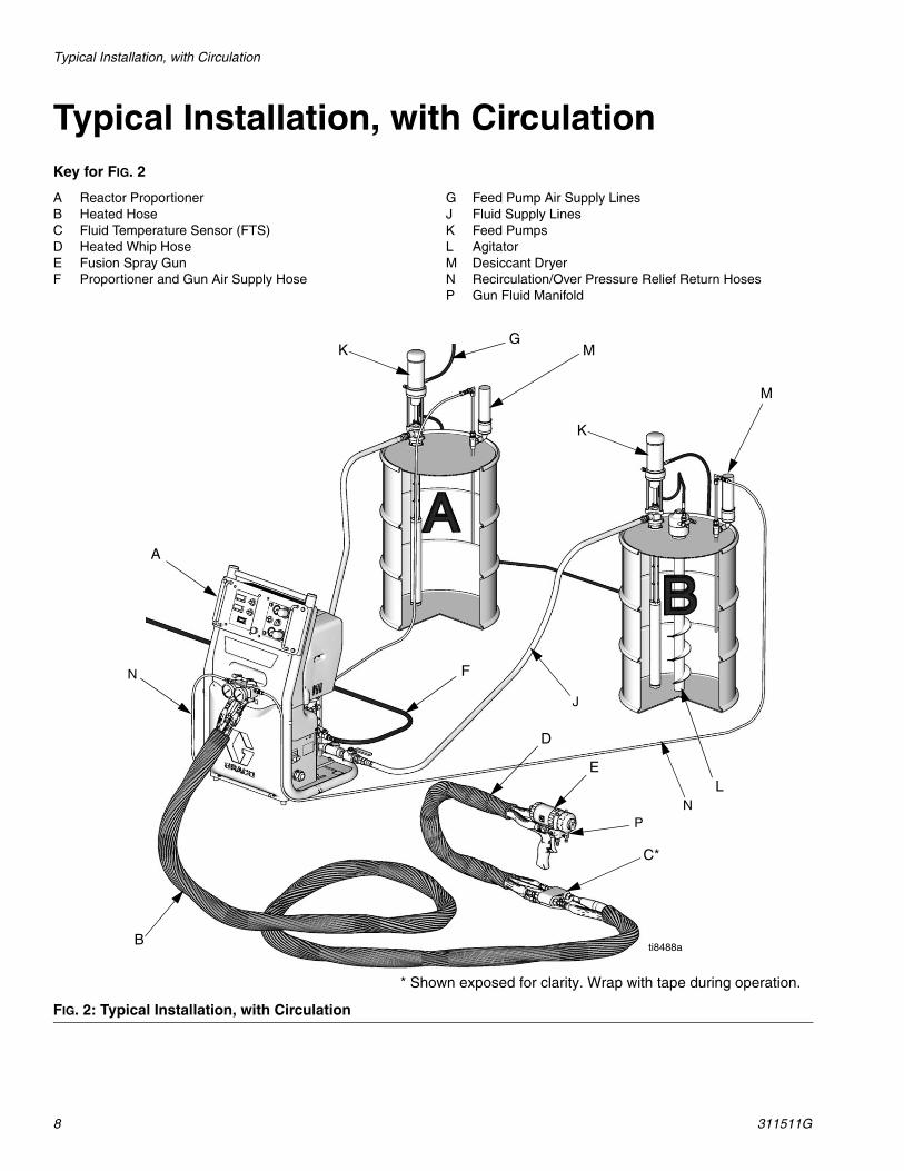
Typical Installation, with CirculationKey for FIG. 2
A Reactor ProportionerB Heated Hose C Fluid Temperature Sensor (FTS)D Heated Whip HoseE Fusion Spray GunF Proportioner and Gun Air Supply Hose
G Feed Pump Air Supply LinesJ Fluid Supply LinesK Feed PumpsL AgitatorM Desiccant DryerN Recirculation/Over Pressure Relief Return HosesP Gun Fluid Manifold
FIG. 2: Typical Installation, with Circulation
A
B
C*
D
E
K
L
M
FN
P
* Shown exposed for clarity. Wrap with tape during operation.
J
N
K
M
G
ti8488a
Moisture Sensitivity of Isocyanates
311511G 9
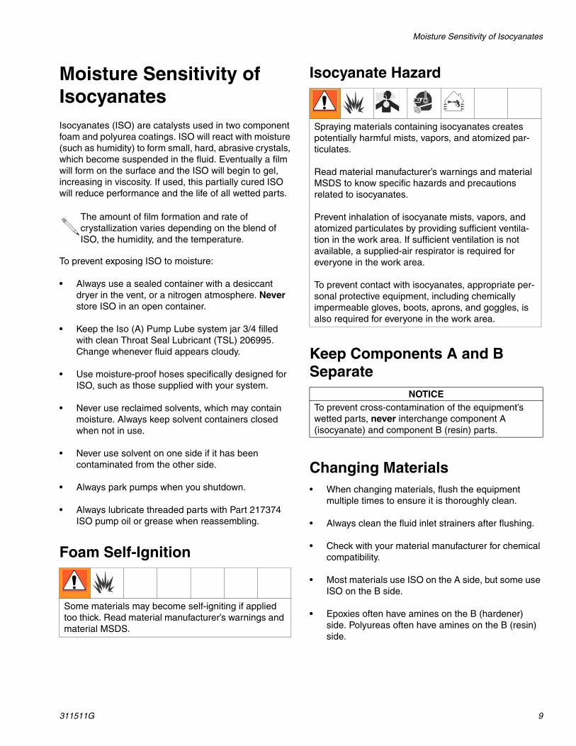
Moisture Sensitivity of IsocyanatesIsocyanates (ISO) are catalysts used in two component foam and polyurea coatings. ISO will react with moisture (such as humidity) to form small, hard, abrasive crystals, which become suspended in the fluid. Eventually a film will form on the surface and the ISO will begin to gel, increasing in viscosity. If used, this partially cured ISO will reduce performance and the life of all wetted parts.
To prevent exposing ISO to moisture:
• Always use a sealed container with a desiccant dryer in the vent, or a nitrogen atmosphere. Never store ISO in an open container.
• Keep the Iso (A) Pump Lube system jar 3/4 filled with clean Throat Seal Lubricant (TSL) 206995. Change whenever fluid appears cloudy.
• Use moisture-proof hoses specifically designed for ISO, such as those supplied with your system.
• Never use reclaimed solvents, which may contain moisture. Always keep solvent containers closed when not in use.
• Never use solvent on one side if it has been contaminated from the other side.
• Always park pumps when you shutdown.
• Always lubricate threaded parts with Part 217374 ISO pump oil or grease when reassembling.
Foam Self-Ignition
Isocyanate Hazard
Keep Components A and B Separate
Changing Materials• When changing materials, flush the equipment
multiple times to ensure it is thoroughly clean.
• Always clean the fluid inlet strainers after flushing.
• Check with your material manufacturer for chemical compatibility.
• Most materials use ISO on the A side, but some use ISO on the B side.
• Epoxies often have amines on the B (hardener) side. Polyureas often have amines on the B (resin) side.
The amount of film formation and rate of crystallization varies depending on the blend of ISO, the humidity, and the temperature.
Some materials may become self-igniting if applied too thick. Read material manufacturer’s warnings and material MSDS.
Spraying materials containing isocyanates creates potentially harmful mists, vapors, and atomized par-ticulates.
Read material manufacturer’s warnings and material MSDS to know specific hazards and precautions related to isocyanates.
Prevent inhalation of isocyanate mists, vapors, and atomized particulates by providing sufficient ventila-tion in the work area. If sufficient ventilation is not available, a supplied-air respirator is required for everyone in the work area.
To prevent contact with isocyanates, appropriate per-sonal protective equipment, including chemically impermeable gloves, boots, aprons, and goggles, is also required for everyone in the work area.
NOTICETo prevent cross-contamination of the equipment’s wetted parts, never interchange component A (isocyanate) and component B (resin) parts.
Component Identification
10 311511G
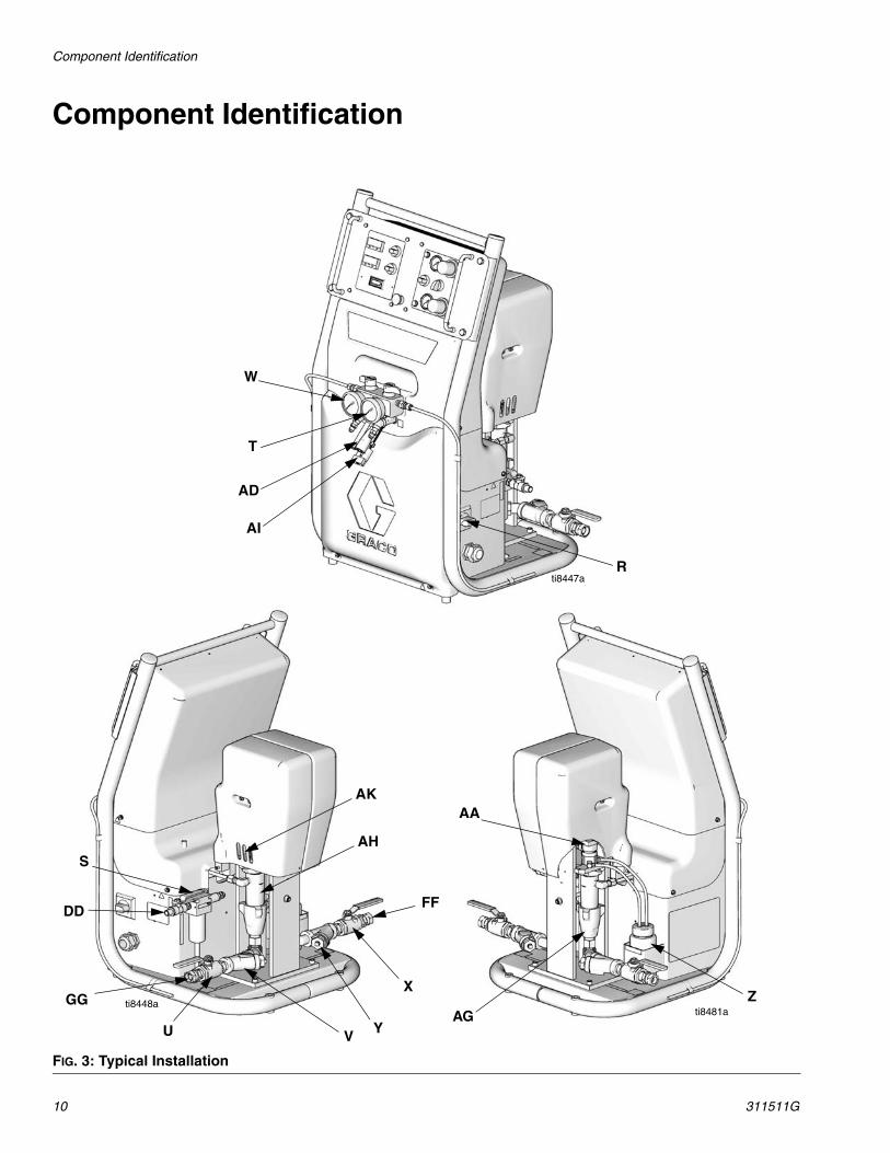
Component Identification
FIG. 3: Typical Installation
AI
T
W
Z
AH
R
AA
S
U VAG
AD
Y
X
ti8447a
ti8448ati8481a
AK
DD
GG
FF
Component Identification
311511G 11
Key:
R Main Disconnect Switch - Controls power to all circuits. It must be ON for proportioning unit to operate. Temperature displays are lit when main switch is ON.
S Main Air Filter - Filters system air supply.
T Resin (B) Pressure Gauge - Displays pressure in resin proportioning system (B side).
U Resin (B) - Inlet Supply Valve
V Resin (B) Fluid Y-Strainer
W ISO (A) Pressure Gauge - Displays pressure in isocyanate proportioning system (A side).
X ISO (A) - Inlet Supply Valve
Y ISO (A) Fluid Y-Strainer
Z ISO (A) Pump Lube System - (A side only)
AA ISO (A) - Packing Nut and Lube Cup - (A side only)
*ABPressure Limit Switches - Factory set to turn off air drive system when proportioning pump exceeds designed operating pressure limit.
*ACPrimary Heater Thermocouple - Senses temperature of primary heater and inputs that information.
AD FTS Jumper Harness - Carries electrical signal from FTS sensor in isocyanate hose to hose temperature controller.
*AEAir Motor Reversing Switch - (Front of air motor) Energizes and de-energizes air solenoid valve coils to reverse direction.
*AFPrimary Heater - Heats material to required dispensing temperature.
AG ISO (A) - (Isocyanate) Proportioning Pump - Draws in and dispenses a fixed volume of isocyanate to gun.
AH Resin (B) Proportioning Pump - Draws in and dispenses a fixed volume of resin to gun.
AI Power-Lock™ Hose Heat Connection - Connects power to heated hoses.
*AJ Primary Heater Over-Temperature Switch - Sends signal to temperature controller if heater exceeds maximum temperature condition.
AK Resin (B) Pump Wet Cup - Access for daily wet cup refill.
* Components not shown.
DD Air Inlet Ball Valve - (3/8 NPT male fitting)
FF ISO (A) Inlet - Fitting (1/2 swivel fitting)
GG Resin (B) - Inlet (3/4 swivel fitting)
Controls and Indicators
12 311511G
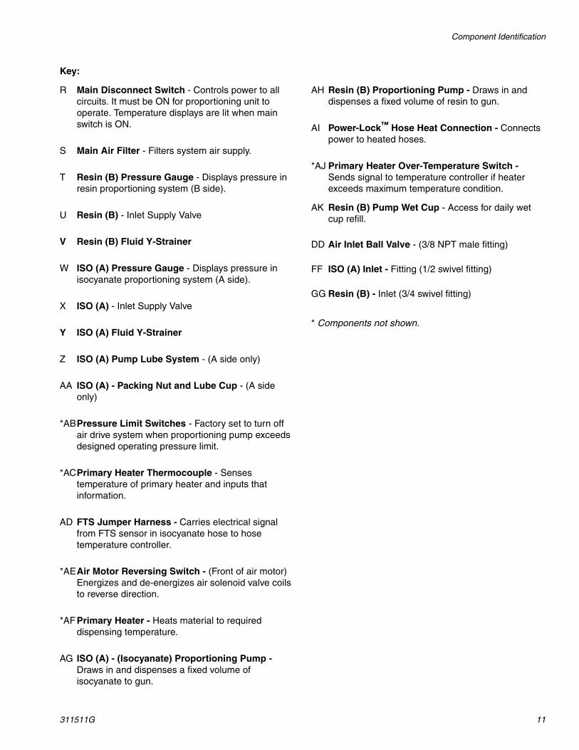
Controls and Indicators
Key:AK Primary Heater Switch - Controls and protects
primary heater. It must be ON and lit green for primary heater to operate.
AL Hose Heater Switch - Controls and protects hose heat circuit. It must be ON and lit green for hose heater to operate.
AM Hose Temperature Controller - Controls temperature of hose heat. Adjust set point to desired temperature. From this point, the temperature control is automatic. Displays current temperature after time-out.
AN Primary Heater Temperature Controller - Controls temperature of primary heater. Adjust set point to desired temperature. From this point, the temperature control is automatic.
AO Pump Mode Function Knob - Controls operation of air drive system.
• OFF - Air drive system is off.
• ON - Must be in this position for unit to operate.
• START - Momentary position that starts the air motor movement and illuminates green light in switch.
AP Park/Run Switch - • PARK - Use this position for shutdown. Stops air
motor at bottom of stroke with proportioning pumps in retracted position when trigger is pulled.
• RUN - Enables Air Motor Power
AQ Pump Directional Indicator Lights (Green) - Indicates direction the proportioning pump travels. Both lights are off when pump switch is OFF or when either proportioning pump exceeds its operating pressure limit switch.
AR Counter - Records cycle count of proportioning pumps. One cycle count equals two strokes (one in each direction). One cycle equals .028 gal. (.106 l).
AS Downstroke Air Pressure Regulator - Controls air pressure to air motor during downstroke.
AT Downstroke Air Pressure Gauge - Displays air pressure in air drive system during downstroke.
AU Upstroke Air Pressure Regulator - Controls air pressure to air motor during upstroke.
AV Upstroke Air Pressure Gauge - Displays air pressure in air drive system during upstroke.
AW Emergency Stop Switch - Shuts off electrical power to pump control and both heat control circuits.
ALAR
AQ
AO ASAT
AV AUAN APAK
AM AW
Pressure Relief Procedure
311511G 13
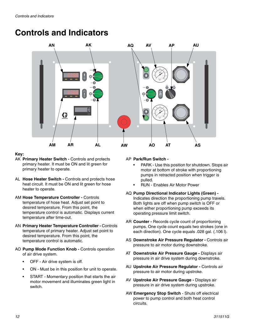
Pressure Relief Procedure
1. Turn off feed pumps and agitator if used.
2. Turn PARK/RUN switch to PARK.
3. Trigger gun to relieve pressure.
4. Turn off air inlet valve.
5. Engage gun piston safety lock.
6. Verify gun fluid manifold valves A and B are closed.
7. Close pump inlet supply valves.
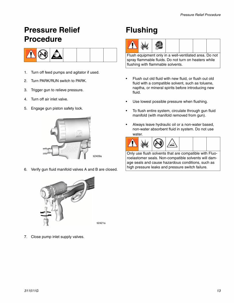
Flushing
• Flush out old fluid with new fluid, or flush out old fluid with a compatible solvent, such as toluene, naptha, or mineral spirits before introducing new fluid.
• Use lowest possible pressure when flushing.
• To flush entire system, circulate through gun fluid manifold (with manifold removed from gun).
• Always leave hydraulic oil or a non-water based, non-water absorbent fluid in system. Do not use water.
ti2409a
ti2421a
Flush equipment only in a well-ventilated area. Do not spray flammable fluids. Do not turn on heaters while flushing with flammable solvents.
Only use flush solvents that are compatible with Fluo-roelastomer seals. Non-compatible solvents will dam-age seals and cause hazardous conditions, such as high pressure leaks and pressure switch failure.
Setup
14 311511G
Setup
Locate Reactor A-201. Locate Reactor A-20 on a level surface and bolt in
place to the floor with 3/8 in. (10 mm) bolts.
• Two bolts through the 2 in. (50 mm) deep caster bushings in the rear.
• Two bolts through the 3-5/8 in. (168 mm) deep caster bushings in the front.
2. Do not expose Reactor A-20 to rain.
3. If you need to move the machine, add provided casters.
4. Lift with hoist only from bar spanning across top of cart.
Determine Power SourceReactor A-20 can be wired to 3 types of power source:
• 230 Volt / 1 Phase
• 230 Volt / 3 Phase Delta
• 380 Volt / 3 Phase WYE(220 Volts to Neutral)
Electrical Requirements
Improper wiring may cause electric shock or other serious injury if work is not performed properly. Have a qualified electrician connect power and ground to main power switch terminals. Ensure your installation complies with all National, State, and Local safety and fire codes.
Also ensure that incoming power is disconnected and locked out at the source.
NOTICEEnsure main power source meets all electrical requirements specified on nameplate of proportioning unit. Also ensure main power source has a dedicated fuse disconnect. Power cord is not supplied.

Setup
311511G 15
Configure to Supply Power
Step One - Connect Electrical Cord
1. Remove and retain two screws from lower front shroud and remove.
2. Connect main power cord to electrical console as follows:
a. Feed power cord through strain relief (SR) on right side of unit. Push black die release lever (RL) down to release contacts block (PD) for easy wiring.
b. Connect power leads to Power Disconnect Switch (PD). Snap contacts block (PD) back onto switch.
c. Tighten strain relief nut.
d. Strain relief accepts cords 0.59 to 1.0 in. (15-25 mm) diameter.
e. Connect ground wire to ground lug (GL).
3. Replace lower front shroud. Reinstall the two screws retained in Step 1.
230V, 1 Phase: Use a screwdriver to connect two power leads to the top terminals N and L2 positions. Connect
green to ground (GND). See page 16 for proper jumper positions.
230V, 3 Phase Delta: Use a screwdriver to connect three power leads to top terminals L1, L2, and L3. Connect green to ground (GND). See page 16 for proper jumper positions.
380V, 3 Phase WYE (as shipped from factory): Use a screwdriver to connect three power leads to the top terminals L1, L2, and L3. Connect neutral to N. Connect green to ground (GND). See page 16 for proper jumper positions.
Both cord connection AND jumper positioning steps on page 16 must be completed.
Disregard terminal numbers on disconnect switch blocks. Wire to positions shown. Terminals will
accept up to #8 AWG (10 mm2) conductors.
SR
PD
ti8608a
GL
RL
Disregard terminal numbers on disconnect switch blocks. Wire to positions shown.
ti8611a
ti8612a
ti8613a
Setup
16 311511G
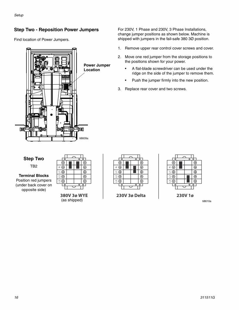
Step Two - Reposition Power Jumpers
Find location of Power Jumpers.
For 230V, 1 Phase and 230V, 3 Phase Installations, change jumper positions as shown below. Machine is shipped with jumpers in the fail-safe 380 3Ø position.
1. Remove upper rear control cover screws and cover.
2. Move one red jumper from the storage positions to the positions shown for your power.
• A flat-blade screwdriver can be used under the ridge on the side of the jumper to remove them.
• Push the jumper firmly into the new position.
3. Replace rear cover and two screws.
Power Jumper Location
ti8609a
Step Two
TB2
Terminal BlocksPosition red jumpers (under back cover on
opposite side)
ti8610a(as shipped)
Setup
311511G 17
Ground System
• Reactor: is grounded through power cord; see page 15.
• Spray gun: connect whip hose ground wire to FTS; see page 18. Do not disconnect wire or spray with-out whip hose.
• Fluid supply containers: follow your local code.
• Object being sprayed: follow your local code.
• Solvent pails used when flushing: follow your local code. Use only metal pails that are conductive. Place them on a grounded surface. Do no place pail on a nonconductive surface, such as paper or cardboard, which interrupts grounding continuity.
• To maintain grounding continuity when flushing or relieving pressure, hold a metal part of spray gun firmly to the side of a grounded metal pail, then trigger gun.
Iso Pump Lubrication System SetupPrepare isocyanate pump lubrication system as follows:
1. Lift lubricant reservoir out of bracket and remove reservoir from cap.
2. Fill reservoir 3/4 full with TSL; see Accessories section in manual 311512.
3. Thread reservoir onto cap assembly and place it into bracket.
The lubrication system is now ready for operation; no priming is required.
Fluid Supply ConnectionsConnect material supply to inlets of proportioning unit as follows:
1. Ensure the A- and B- inlet ball valves (U,X) on proportioning unit are closed.
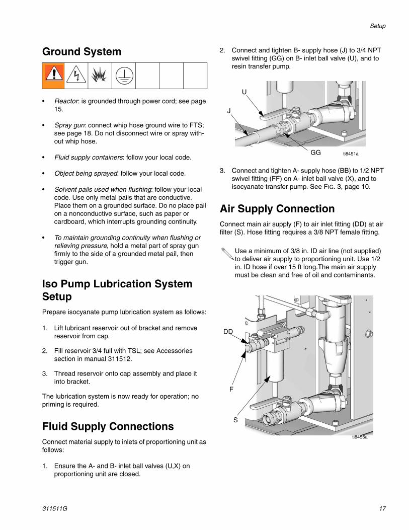
2. Connect and tighten B- supply hose (J) to 3/4 NPT swivel fitting (GG) on B- inlet ball valve (U), and to resin transfer pump.
3. Connect and tighten A- supply hose (BB) to 1/2 NPT swivel fitting (FF) on A- inlet ball valve (X), and to isocyanate transfer pump. See FIG. 3, page 10.
Air Supply ConnectionConnect main air supply (F) to air inlet fitting (DD) at air filter (S). Hose fitting requires a 3/8 NPT female fitting.
Use a minimum of 3/8 in. ID air line (not supplied) to deliver air supply to proportioning unit. Use 1/2 in. ID hose if over 15 ft long.The main air supply must be clean and free of oil and contaminants.
U
J
ti8451aGG
S
F
DD
ti8456a
Setup
18 311511G
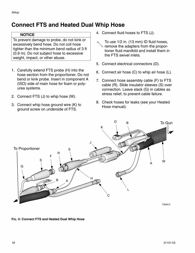
Connect FTS and Heated Dual Whip Hose
1. Carefully extend FTS probe (H) into the hose section from the proportioner. Do not bend or kink probe. Insert in component A (ISO) side of main hose for foam or poly-urea systems.
2. Connect FTS (J) to whip hose (W).
3. Connect whip hose ground wire (K) to ground screw on underside of FTS.
4. Connect fluid hoses to FTS (J).
5. Connect electrical connectors (D).
6. Connect air hose (C) to whip air hose (L).
7. Connect hose assembly cable (F) to FTS cable (R). Slide insulator sleeves (S) over connection. Leave slack (G) in cables as stress relief, to prevent cable failure.
8. Check hoses for leaks (see your Heated Hose manual).
FIG. 4: Connect FTS and Heated Dual Whip Hose
NOTICETo prevent damage to probe, do not kink or excessively bend hose. Do not coil hose tighter than the minimum bend radius of 3 ft (0.9 m). Do not subject hose to excessive weight, impact, or other abuse.
To use 1/2 in. (13 mm) ID fluid hoses, remove the adapters from the propor-tioner fluid manifold and install them in the FTS swivel inlets.
B A
A
BK
H
C
D
J
L
TI9581C
F
G
WS
SR
To Gun
To Proportioner
Setup
311511G 19
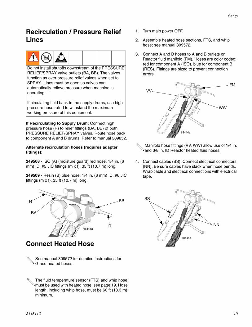
Recirculation / Pressure Relief Lines
If Recirculating to Supply Drum: Connect high pressure hose (R) to relief fittings (BA, BB) of both PRESSURE RELIEF/SPRAY valves. Route hose back to component A and B drums. Refer to manual 309852.
Alternate recirculation hoses (requires adapter fittings):
249508 - ISO (A) (moisture guard) red hose, 1/4 in. (6 mm) ID; #5 JIC fittings (m x f); 35 ft (10.7 m) long.
249509 - Resin (B) blue hose; 1/4 in. (6 mm) ID, #6 JIC fittings (m x f), 35 ft (10.7 m) long.
Connect Heated Hose
1. Turn main power OFF.
2. Assemble heated hose sections, FTS, and whip hose; see manual 309572.
3. Connect A and B hoses to A and B outlets on Reactor fluid manifold (FM). Hoses are color coded: red for component A (ISO), blue for component B (RES). Fittings are sized to prevent connection errors.
4. Connect cables (SS). Connect electrical connectors (NN). Be sure cables have slack when hose bends. Wrap cable and electrical connections with electrical tape.
Do not install shutoffs downstream of the PRESSURE RELIEF/SPRAY valve outlets (BA, BB). The valves function as over pressure relief valves when set to SPRAY. Lines must be open so valves can automatically relieve pressure when machine is operating.
If circulating fluid back to the supply drums, use high pressure hose rated to withstand the maximum working pressure of this equipment.
See manual 309572 for detailed instructions for Graco heated hoses.
The fluid temperature sensor (FTS) and whip hose must be used with heated hose; see page 19. Hose length, including whip hose, must be 60 ft (18.3 m) minimum.
BB
BA
ti8441a
R
R
Manifold hose fittings (VV, WW) allow use of 1/4 in. and 3/8 in. ID Reactor heated fluid hoses.
FM
VV
WW
ti8444a
ti8444a
SS
NN
Setup
20 311511G
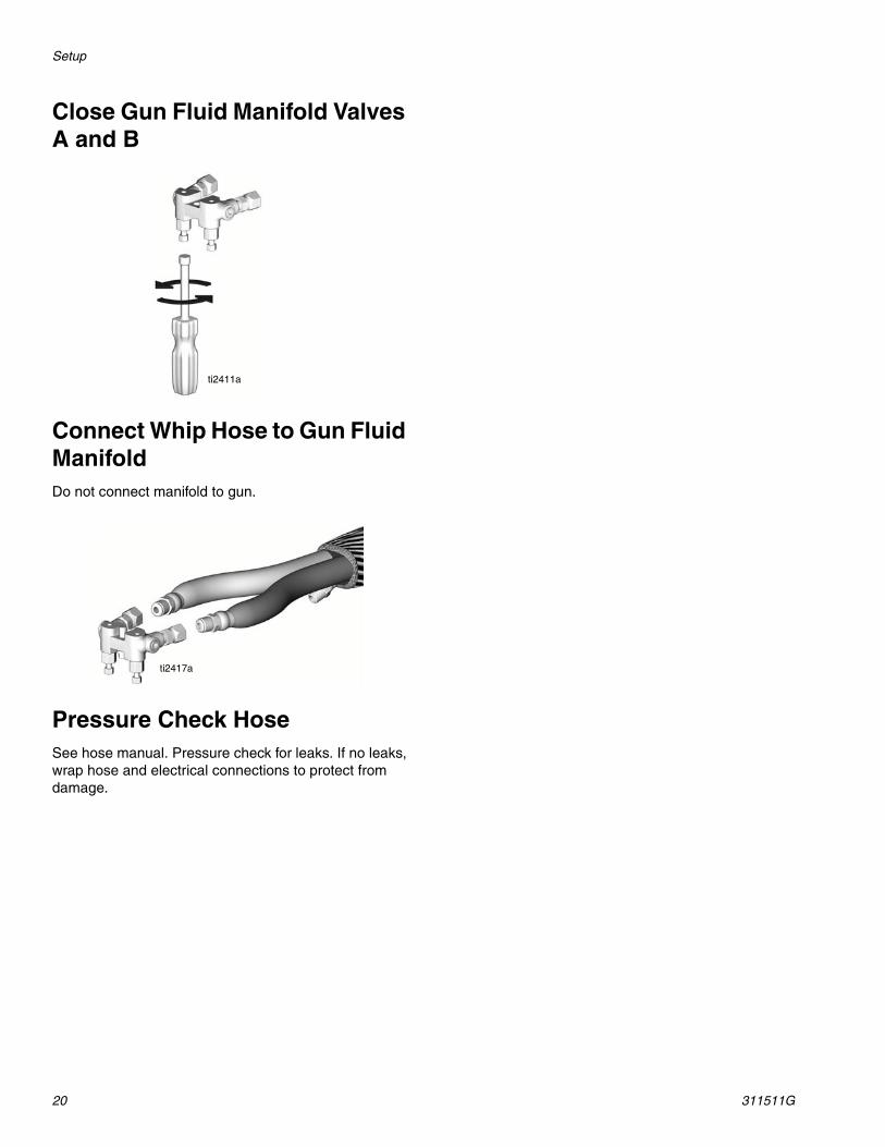
Close Gun Fluid Manifold Valves A and B
Connect Whip Hose to Gun Fluid ManifoldDo not connect manifold to gun.
Pressure Check HoseSee hose manual. Pressure check for leaks. If no leaks, wrap hose and electrical connections to protect from damage.
ti2411a
ti2417a
Initial Startup
311511G 21
Initial Startup
Fluid Temperature Sensor (FTS) Calibration
1. Before turning on the unit, ensure all hoses and cables are properly connected. To ensure that the FTS in the hose is at the same temperature as the heaters, keep heat off and store the hose FTS near the machine for several minutes.
2. While holding down the temperature unit button (Fahrenheit - “F” or Celsius - “C”) turn the Reactor main power ON.
3. Hold the temperature unit button until temperature is shown on the display. The fluid temperature sensor is now correctly calibrated.
Load Fluid with Feed Pumps
1. Check that Setup process is complete; see page 14.
2. Turn on component B agitator, if used.
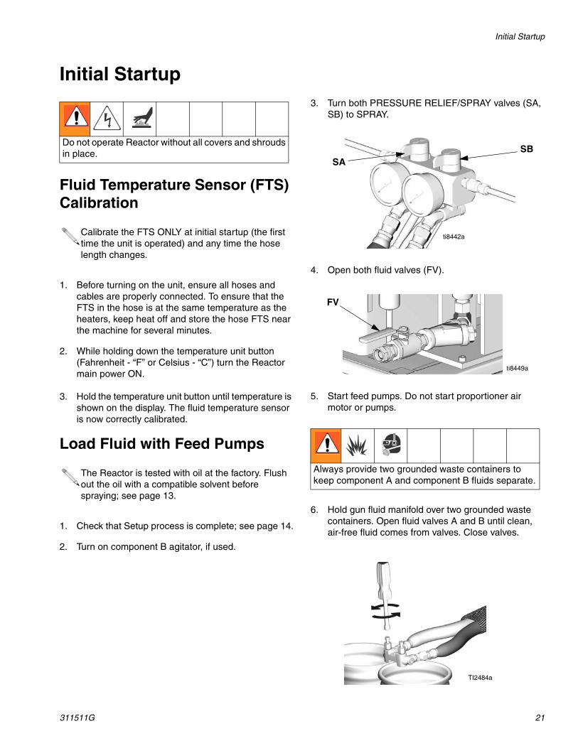
3. Turn both PRESSURE RELIEF/SPRAY valves (SA, SB) to SPRAY.
4. Open both fluid valves (FV).
5. Start feed pumps. Do not start proportioner air motor or pumps.
6. Hold gun fluid manifold over two grounded waste containers. Open fluid valves A and B until clean, air-free fluid comes from valves. Close valves.
Do not operate Reactor without all covers and shrouds in place.
Calibrate the FTS ONLY at initial startup (the first time the unit is operated) and any time the hose length changes.
The Reactor is tested with oil at the factory. Flush out the oil with a compatible solvent before spraying; see page 13.
Always provide two grounded waste containers to keep component A and component B fluids separate.
SBSA
ti8442a
FV
ti8449a
TI2484a
Initial Startup
22 311511G
Digital Temperature Controllers
The proportioner has two temperature controllers that automatically manage the temperature for the primary heater and the hose heat.
Controller Screens
Push the left side scroll button to cycle through the following screens.
To change or enter the set point, proceed as follows:
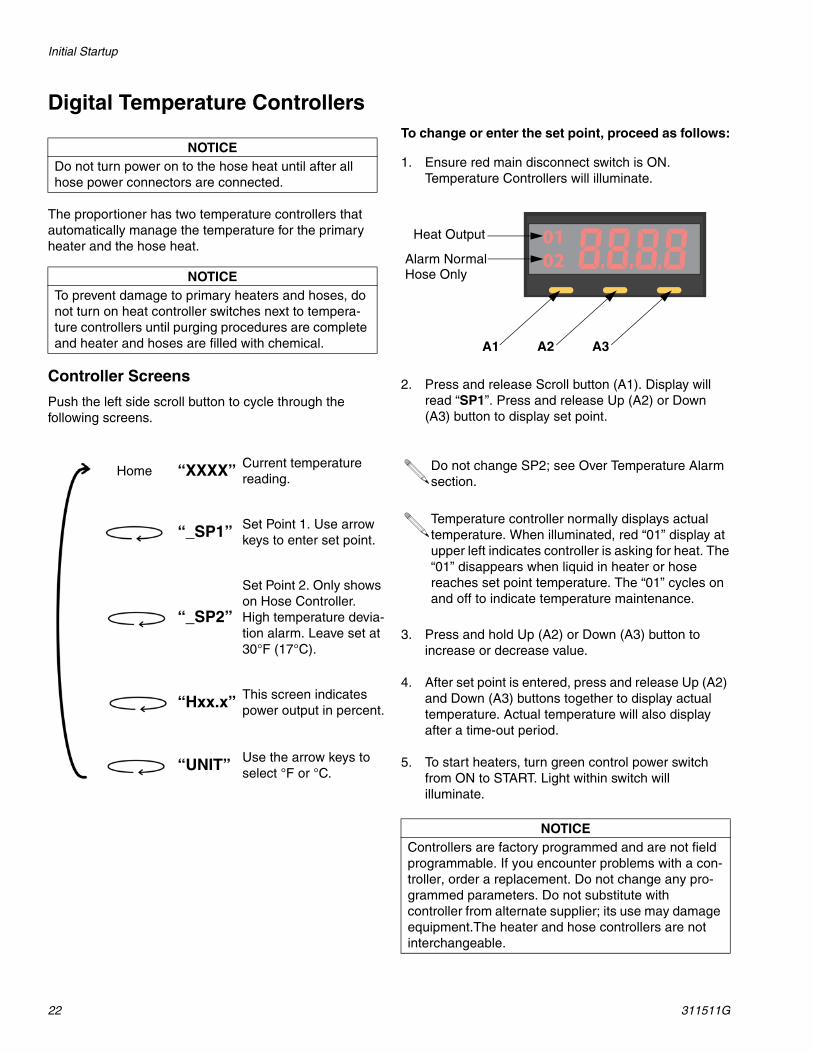
1. Ensure red main disconnect switch is ON. Temperature Controllers will illuminate.
2. Press and release Scroll button (A1). Display will read “SP1”. Press and release Up (A2) or Down (A3) button to display set point.
3. Press and hold Up (A2) or Down (A3) button to increase or decrease value.
4. After set point is entered, press and release Up (A2) and Down (A3) buttons together to display actual temperature. Actual temperature will also display after a time-out period.
5. To start heaters, turn green control power switch from ON to START. Light within switch will illuminate.
NOTICEDo not turn power on to the hose heat until after all hose power connectors are connected.
NOTICETo prevent damage to primary heaters and hoses, do not turn on heat controller switches next to tempera-ture controllers until purging procedures are complete and heater and hoses are filled with chemical.
Home “XXXX” Current temperature reading.
“_SP1” Set Point 1. Use arrow keys to enter set point.
“_SP2”
Set Point 2. Only shows on Hose Controller. High temperature devia-tion alarm. Leave set at 30°F (17°C).
“Hxx.x” This screen indicates power output in percent.
“UNIT” Use the arrow keys to select °F or °C.
Do not change SP2; see Over Temperature Alarm section.
Temperature controller normally displays actual temperature. When illuminated, red “01” display at upper left indicates controller is asking for heat. The “01” disappears when liquid in heater or hose reaches set point temperature. The “01” cycles on and off to indicate temperature maintenance.
NOTICEControllers are factory programmed and are not field programmable. If you encounter problems with a con-troller, order a replacement. Do not change any pro-grammed parameters. Do not substitute with controller from alternate supplier; its use may damage equipment.The heater and hose controllers are not interchangeable.
A1 A2 A3
Heat Output
Alarm NormalHose Only
Initial Startup
311511G 23
Change Between Fahrenheit and Celsius
The temperature controller is factory-set to display in Fahrenheit units.
To change to Celsius units:
1. Press and release Scroll button (A1) until Controller displays “UNIT”.
2. Press and release Down button (A3) once to display “F”.
3. Press and release Down button (A3) once again to display “C”.
4. Press and release Scroll button (A1) twice. Controller will display Celsius units.
To change back to Fahrenheit units:
1. Press and release Scroll button (A1) until Controller displays “UNIT”.
2. Press and release Down button (A3) once to display “C”.
3. Press and release Down button (A3) once again to display “F”.
4. Press and release Scroll button (A1) twice. Controller will display Fahrenheit units.
Initial Startup
24 311511G
Over Temperature AlarmsBoth the fluid heater and the hose heat have over temperature alarms that will turn off the heat zone if high temperatures are detected. If this happens, the green light in the switch for that heat zone will go out.
The fluid heater has a fixed temperature switch on the aluminum heater that opens at 230 °F (110 °C) and turns off the heat zone. The temperature switch will automatically reset, but the heat zone will need to be manually restarted. The over-temperature condition should never happen unless the solid state relay (165SSR) fails closed.
The hose heat uses the temperature controller alarm, monitoring the hose thermocouple (FTS) to watch for high temperature conditions. This alarm is controlled by SP2 (Set Point 2) and is factory set for 30 °F (17 °C). This means that the alarm set point is 30° (17 °C) over the SP1 operating temperature set point. Under normal conditions, the output 02 light will be lit on the hose controller. This output holds the hose heat power contact ON and lights the green light in the switch any time power is available to heat the hose. If the hose temperature reading is 30 °F (17 °C) (SP2 setting) over the temperature set point (SP1), the output 02 light and switch light will go out. Hose heat will only return after a manual START of the control switch, after alarm conditions are gone.
Fluid Heater Temperature OffsetThe fluid heater has been calibrated to provide setpoint temperature fluid under flow conditions. When the machine is powered up and no heat has been turned on, the heater display will read somewhat lower than the hose display. This is normal. The hose display has no offset and will always read the actual temperature at the sensor in the hose.
Hose Heat Manual ModeIf the hose temperature controller does not see the Fluid Temperature Sensor (FTS), it will shut off the hose heat and give a flashing error alternating between:
SbEr = Sensor break errorH20.0 = Heat output 20%
The hose can be manually heated by turning the hose back on with the hose switch and green light. The up/down arrows can be used to adjust the default 20% power output.
There is no monitoring or alarm in manual mode. You must monitor the temperature by inserting a probe thermometer inside the hose insulation against the hose. The thermometer will read 10-20 °F less than actual fluid temperature. Repair the temperature sensor or cable as soon as possible to avoid damaging the heated hose.
The hose heat deviation alarm is controlled by the SP2 setpoint. This is factory set to 30 °F (17 °C) and should not be changed. A loss of alarm function and loss of automatic over temperature shut-down could result.
Initial Startup
311511G 25
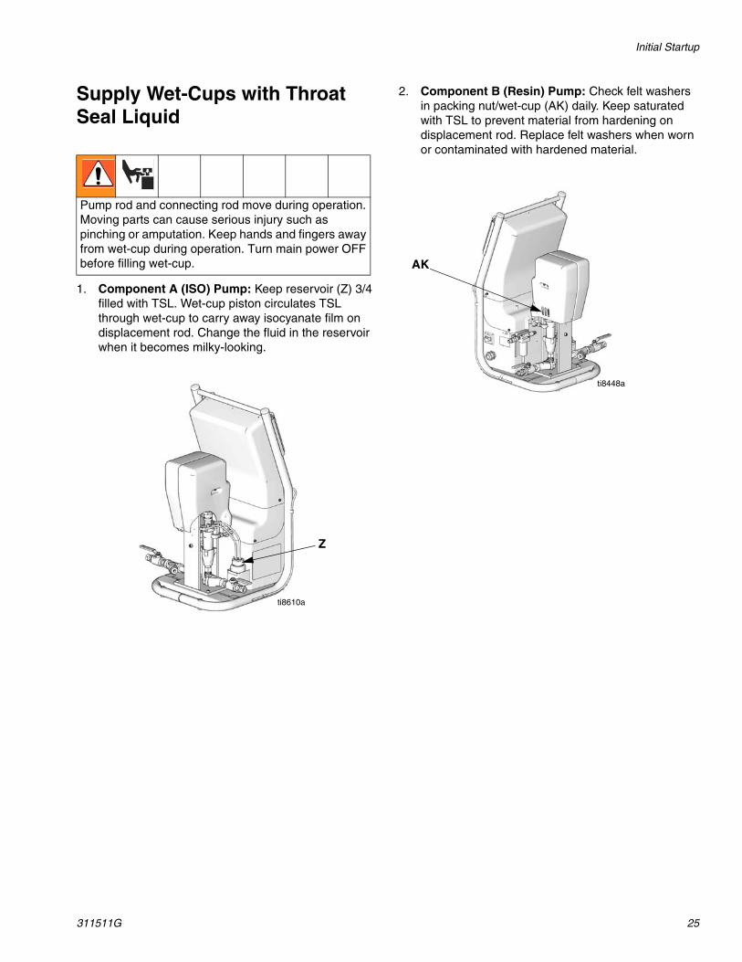
Supply Wet-Cups with Throat Seal Liquid
1. Component A (ISO) Pump: Keep reservoir (Z) 3/4 filled with TSL. Wet-cup piston circulates TSL through wet-cup to carry away isocyanate film on displacement rod. Change the fluid in the reservoir when it becomes milky-looking.
2. Component B (Resin) Pump: Check felt washers in packing nut/wet-cup (AK) daily. Keep saturated with TSL to prevent material from hardening on displacement rod. Replace felt washers when worn or contaminated with hardened material.
Pump rod and connecting rod move during operation. Moving parts can cause serious injury such as pinching or amputation. Keep hands and fingers away from wet-cup during operation. Turn main power OFF before filling wet-cup.
Z
ti8610a
AK
ti8448a
Spraying Setup
26 311511G
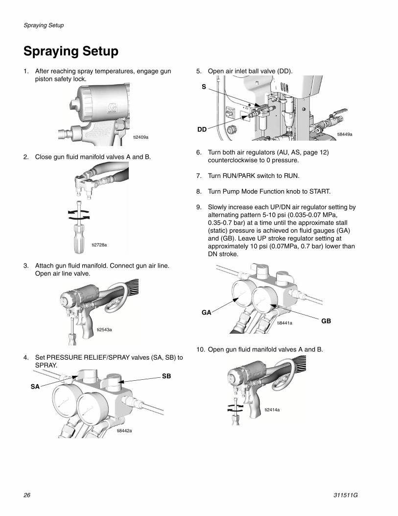
Spraying Setup1. After reaching spray temperatures, engage gun
piston safety lock.
2. Close gun fluid manifold valves A and B.
3. Attach gun fluid manifold. Connect gun air line. Open air line valve.
4. Set PRESSURE RELIEF/SPRAY valves (SA, SB) to SPRAY.
5. Open air inlet ball valve (DD).
6. Turn both air regulators (AU, AS, page 12) counterclockwise to 0 pressure.
7. Turn RUN/PARK switch to RUN.
8. Turn Pump Mode Function knob to START.
9. Slowly increase each UP/DN air regulator setting by alternating pattern 5-10 psi (0.035-0.07 MPa, 0.35-0.7 bar) at a time until the approximate stall (static) pressure is achieved on fluid gauges (GA) and (GB). Leave UP stroke regulator setting at approximately 10 psi (0.07MPa, 0.7 bar) lower than DN stroke.
10. Open gun fluid manifold valves A and B.
ti2409a
ti2728a
ti2543a
SB
SA
ti8442a
DDti8449a
S
ti8441a
GAGB
ti2414a
Spraying Setup
311511G 27
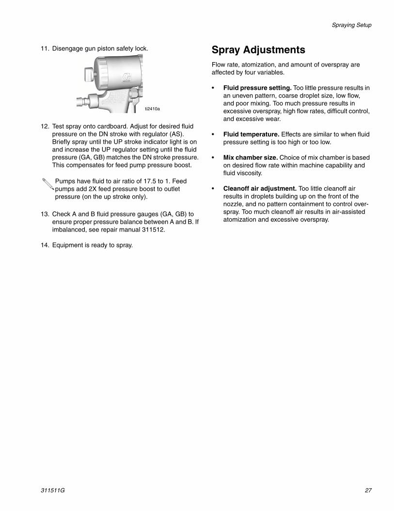
11. Disengage gun piston safety lock.
12. Test spray onto cardboard. Adjust for desired fluid pressure on the DN stroke with regulator (AS). Briefly spray until the UP stroke indicator light is on and increase the UP regulator setting until the fluid pressure (GA, GB) matches the DN stroke pressure. This compensates for feed pump pressure boost.
13. Check A and B fluid pressure gauges (GA, GB) to ensure proper pressure balance between A and B. If imbalanced, see repair manual 311512.
14. Equipment is ready to spray.
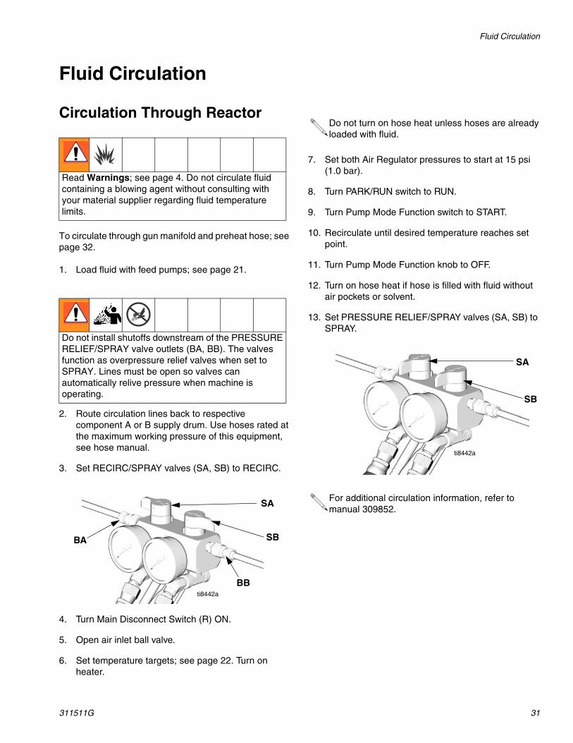
Spray AdjustmentsFlow rate, atomization, and amount of overspray are affected by four variables.
• Fluid pressure setting. Too little pressure results in an uneven pattern, coarse droplet size, low flow, and poor mixing. Too much pressure results in excessive overspray, high flow rates, difficult control, and excessive wear.
• Fluid temperature. Effects are similar to when fluid pressure setting is too high or too low.
• Mix chamber size. Choice of mix chamber is based on desired flow rate within machine capability and fluid viscosity.
• Cleanoff air adjustment. Too little cleanoff air results in droplets building up on the front of the nozzle, and no pattern containment to control over-spray. Too much cleanoff air results in air-assisted atomization and excessive overspray.
Pumps have fluid to air ratio of 17.5 to 1. Feed pumps add 2X feed pressure boost to outlet pressure (on the up stroke only).
ti2410a
Shutdown
28 311511G
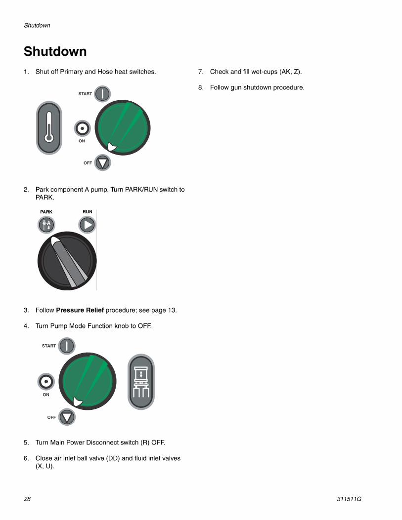
Shutdown1. Shut off Primary and Hose heat switches.
2. Park component A pump. Turn PARK/RUN switch to PARK.
3. Follow Pressure Relief procedure; see page 13.
4. Turn Pump Mode Function knob to OFF.
5. Turn Main Power Disconnect switch (R) OFF.
6. Close air inlet ball valve (DD) and fluid inlet valves (X, U).
7. Check and fill wet-cups (AK, Z).
8. Follow gun shutdown procedure.

Operation
311511G 29
Operation
Daily Start-up Procedure
1. Check condition isocyanate lubrication system and service as required. Change pump lubricant when it shows signs of change to a milky color.
2. Ensure supply fluid is at correct temperature as recommended by chemical system supplier. Ensure individual chemicals are correctly agitated within their drums/day tanks, and moisture protection system is properly set for operation. Recirculate heated fluid back to supply drums if necessary; see page 31.
3. Turn on main air supply to transfer pumps.
4. Pressurize transfer pumps and open A- and B-inlet supply valves.
5. Open air inlet ball valve.
6. Switch ON main power disconnect switch.
7. Uncoil heated hose.
8. Check that hose setpoint temperature is correct.
9. Turn hose heat control switch past ON to START. Switch will illuminate.
10. The hose power controller automatically adjusts the hose current to the hose to compensate for hose length and ambient temperature. Wait for actual hose temperature readout to match hose setpoint temperature.
11. Turn on primary heater switch past ON to START. Ensure heater setpoint is correct. Wait for operating temperature to be reached.
12. Set PRESSURE RELIEF/SPRAY valves (SA, SB) to SPRAY.
13. Turn PARK/RUN switch to RUN.
14. Turn Pump Mode Function switch to ON and momentarily to START. Pumps will pressurize the fluid according to air regulator pressure.
15. Check A and B fluid pressure gauges (GA, GB) to ensure proper pressure balance between A and B. If imbalanced, bleed off the high side with valves SA and SB until balanced.
The daily start-up procedures describe normal operation. Assume that all temperature and pressure settings have been previously set, but that the heating system is not up to operating temperature.
NOTICEUncoil heated hoses before turning on hose heater switch to prevent overheating and hot spots within hose.
To prevent excessive pressure build-up in heated hoses, always bring hoses and primary heater up to operating temperature before turning on pump switch.
ti8442a
SB
SA
ti8442a
GAGB
Operation
30 311511G
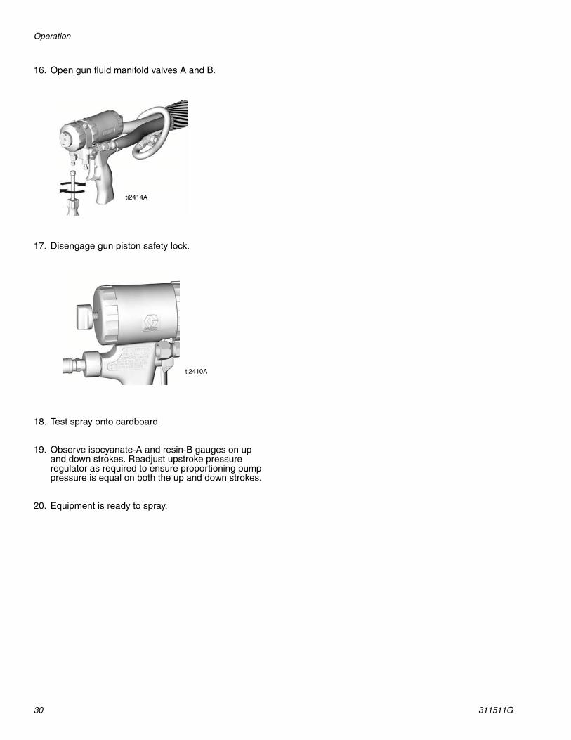
16. Open gun fluid manifold valves A and B.
17. Disengage gun piston safety lock.
18. Test spray onto cardboard.
19. Observe isocyanate-A and resin-B gauges on up and down strokes. Readjust upstroke pressure regulator as required to ensure proportioning pump pressure is equal on both the up and down strokes.
20. Equipment is ready to spray.
ti2414A
ti2410A
Fluid Circulation
311511G 31
Fluid Circulation
Circulation Through Reactor
To circulate through gun manifold and preheat hose; see page 32.
1. Load fluid with feed pumps; see page 21.
2. Route circulation lines back to respective component A or B supply drum. Use hoses rated at the maximum working pressure of this equipment, see hose manual.
3. Set RECIRC/SPRAY valves (SA, SB) to RECIRC.
4. Turn Main Disconnect Switch (R) ON.
5. Open air inlet ball valve.
6. Set temperature targets; see page 22. Turn on heater.
7. Set both Air Regulator pressures to start at 15 psi (1.0 bar).
8. Turn PARK/RUN switch to RUN.
9. Turn Pump Mode Function switch to START.
10. Recirculate until desired temperature reaches set point.
11. Turn Pump Mode Function knob to OFF.
12. Turn on hose heat if hose is filled with fluid without air pockets or solvent.
13. Set PRESSURE RELIEF/SPRAY valves (SA, SB) to SPRAY.
Read Warnings; see page 4. Do not circulate fluid containing a blowing agent without consulting with your material supplier regarding fluid temperature limits.
Do not install shutoffs downstream of the PRESSURE RELIEF/SPRAY valve outlets (BA, BB). The valves function as overpressure relief valves when set to SPRAY. Lines must be open so valves can automatically relive pressure when machine is operating.
SB
SA
BB
BA
ti8442a
Do not turn on hose heat unless hoses are already loaded with fluid.
For additional circulation information, refer to manual 309852.
ti8442a
SA
SB
Fluid Circulation
32 311511G
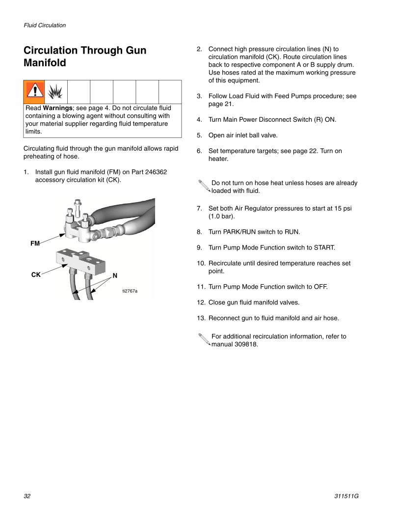
Circulation Through Gun Manifold
Circulating fluid through the gun manifold allows rapid preheating of hose.
1. Install gun fluid manifold (FM) on Part 246362 accessory circulation kit (CK).
2. Connect high pressure circulation lines (N) to circulation manifold (CK). Route circulation lines back to respective component A or B supply drum. Use hoses rated at the maximum working pressure of this equipment.
3. Follow Load Fluid with Feed Pumps procedure; see page 21.
4. Turn Main Power Disconnect Switch (R) ON.
5. Open air inlet ball valve.
6. Set temperature targets; see page 22. Turn on heater.
7. Set both Air Regulator pressures to start at 15 psi (1.0 bar).
8. Turn PARK/RUN switch to RUN.
9. Turn Pump Mode Function switch to START.
10. Recirculate until desired temperature reaches set point.
11. Turn Pump Mode Function switch to OFF.
12. Close gun fluid manifold valves.
13. Reconnect gun to fluid manifold and air hose.
Read Warnings; see page 4. Do not circulate fluid containing a blowing agent without consulting with your material supplier regarding fluid temperature limits.
FM
CK N
ti2767a
Do not turn on hose heat unless hoses are already loaded with fluid.
For additional recirculation information, refer to manual 309818.
Fluid Circulation
311511G 33
Maintenance• Check and add TSL to B side pump wet-cup daily.
• Check ISO lube bottle for significant discoloration or crystallization daily. Replace with fresh TSL when needed.
• Ensure ISO (A) pump is down and in PARK position during every shutdown.
• Keep any ISO (A) fluid from being exposed to atmo-sphere to prevent crystallization.
• Remove inlet filter screen plug (V, Y) and clean screens if increased unbalanced pressures between A and B is noticed or as needed for fluids used. Also clean after flushing.
• Close gun fluid shutoff valves when not in use.
• If using a Fusion Air Purge gun, add grease with grease gun per manual.
• Clean gun filter screens and mix chamber ports reg-ularly, or when increased unbalanced pressures between A and B is noticed. See gun manual.
• Use lithium grease or Iso Pump Oil on all threaded fluid fittings on the “A” side.
Technical Data
34 311511G
Technical Data
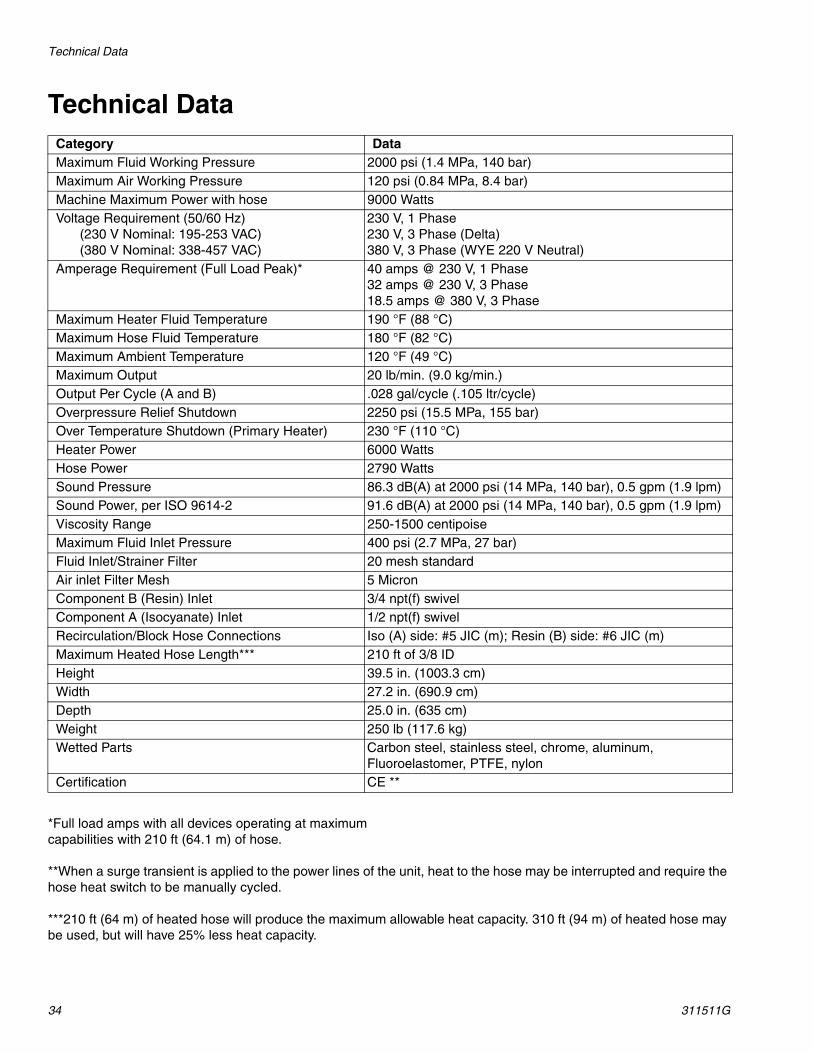
*Full load amps with all devices operating at maximum capabilities with 210 ft (64.1 m) of hose.
**When a surge transient is applied to the power lines of the unit, heat to the hose may be interrupted and require the hose heat switch to be manually cycled.
***210 ft (64 m) of heated hose will produce the maximum allowable heat capacity. 310 ft (94 m) of heated hose may be used, but will have 25% less heat capacity.
Category DataMaximum Fluid Working Pressure 2000 psi (1.4 MPa, 140 bar)Maximum Air Working Pressure 120 psi (0.84 MPa, 8.4 bar)Machine Maximum Power with hose 9000 WattsVoltage Requirement (50/60 Hz)
(230 V Nominal: 195-253 VAC)(380 V Nominal: 338-457 VAC)
230 V, 1 Phase230 V, 3 Phase (Delta)380 V, 3 Phase (WYE 220 V Neutral)
Amperage Requirement (Full Load Peak)* 40 amps @ 230 V, 1 Phase32 amps @ 230 V, 3 Phase18.5 amps @ 380 V, 3 Phase
Maximum Heater Fluid Temperature 190 °F (88 °C)Maximum Hose Fluid Temperature 180 °F (82 °C) Maximum Ambient Temperature 120 °F (49 °C)Maximum Output 20 lb/min. (9.0 kg/min.)Output Per Cycle (A and B) .028 gal/cycle (.105 ltr/cycle)Overpressure Relief Shutdown 2250 psi (15.5 MPa, 155 bar)Over Temperature Shutdown (Primary Heater) 230 °F (110 °C)Heater Power 6000 WattsHose Power 2790 WattsSound Pressure 86.3 dB(A) at 2000 psi (14 MPa, 140 bar), 0.5 gpm (1.9 lpm)Sound Power, per ISO 9614-2 91.6 dB(A) at 2000 psi (14 MPa, 140 bar), 0.5 gpm (1.9 lpm)Viscosity Range 250-1500 centipoiseMaximum Fluid Inlet Pressure 400 psi (2.7 MPa, 27 bar)Fluid Inlet/Strainer Filter 20 mesh standardAir inlet Filter Mesh 5 MicronComponent B (Resin) Inlet 3/4 npt(f) swivelComponent A (Isocyanate) Inlet 1/2 npt(f) swivelRecirculation/Block Hose Connections Iso (A) side: #5 JIC (m); Resin (B) side: #6 JIC (m)Maximum Heated Hose Length*** 210 ft of 3/8 IDHeight 39.5 in. (1003.3 cm)Width 27.2 in. (690.9 cm)Depth 25.0 in. (635 cm)Weight 250 lb (117.6 kg)Wetted Parts Carbon steel, stainless steel, chrome, aluminum,
Fluoroelastomer, PTFE, nylonCertification CE **

Technical Data
311511G 35

All written and visual data contained in this document reflects the latest product information available at the time of publication. Graco reserves the right to make changes at any time without notice.
Original instructions. This manual contains English. MM 311511
Graco Headquarters: MinneapolisInternational Offices: Belgium, China, Japan, Korea
GRACO INC. P.O. BOX 1441 MINNEAPOLIS, MN 55440-1441Copyright 2006, Graco Inc. is registered to ISO 9001
www.graco.comRevised 01/2011
Graco Standard WarrantyGraco warrants all equipment referenced in this document which is manufactured by Graco and bearing its name to be free from defects in material and workmanship on the date of sale to the original purchaser for use. With the exception of any special, extended, or limited warranty published by Graco, Graco will, for a period of twelve months from the date of sale, repair or replace any part of the equipment determined by Graco to be defective. This warranty applies only when the equipment is installed, operated and maintained in accordance with Graco’s written recommendations.
This warranty does not cover, and Graco shall not be liable for general wear and tear, or any malfunction, damage or wear caused by faulty installation, misapplication, abrasion, corrosion, inadequate or improper maintenance, negligence, accident, tampering, or substitution of non-Graco component parts. Nor shall Graco be liable for malfunction, damage or wear caused by the incompatibility of Graco equipment with structures, accessories, equipment or materials not supplied by Graco, or the improper design, manufacture, installation, operation or maintenance of structures, accessories, equipment or materials not supplied by Graco.
This warranty is conditioned upon the prepaid return of the equipment claimed to be defective to an authorized Graco distributor for verification of the claimed defect. If the claimed defect is verified, Graco will repair or replace free of charge any defective parts. The equipment will be returned to the original purchaser transportation prepaid. If inspection of the equipment does not disclose any defect in material or workmanship, repairs will be made at a reasonable charge, which charges may include the costs of parts, labor, and transportation.
THIS WARRANTY IS EXCLUSIVE, AND IS IN LIEU OF ANY OTHER WARRANTIES, EXPRESS OR IMPLIED, INCLUDING BUT NOT LIMITED TO WARRANTY OF MERCHANTABILITY OR WARRANTY OF FITNESS FOR A PARTICULAR PURPOSE.
Graco’s sole obligation and buyer’s sole remedy for any breach of warranty shall be as set forth above. The buyer agrees that no other remedy (including, but not limited to, incidental or consequential damages for lost profits, lost sales, injury to person or property, or any other incidental or consequential loss) shall be available. Any action for breach of warranty must be brought within two (2) years of the date of sale.
GRACO MAKES NO WARRANTY, AND DISCLAIMS ALL IMPLIED WARRANTIES OF MERCHANTABILITY AND FITNESS FOR A PARTICULAR PURPOSE, IN CONNECTION WITH ACCESSORIES, EQUIPMENT, MATERIALS OR COMPONENTS SOLD BUT NOT MANUFACTURED BY GRACO. These items sold, but not manufactured by Graco (such as electric motors, switches, hose, etc.), are subject to the warranty, if any, of their manufacturer. Graco will provide purchaser with reasonable assistance in making any claim for breach of these warranties.
In no event will Graco be liable for indirect, incidental, special or consequential damages resulting from Graco supplying equipment hereunder, or the furnishing, performance, or use of any products or other goods sold hereto, whether due to a breach of contract, breach of warranty, the negligence of Graco, or otherwise.
FOR GRACO CANADA CUSTOMERSThe Parties acknowledge that they have required that the present document, as well as all documents, notices and legal proceedings entered into, given or instituted pursuant hereto or relating directly or indirectly hereto, be drawn up in English. Les parties reconnaissent avoir convenu que la rédaction du présente document sera en Anglais, ainsi que tous documents, avis et procédures judiciaires exécutés, donnés ou intentés, à la suite de ou en rapport, directement ou indirectement, avec les procédures concernées.
Graco Information For the latest information about Graco products, visit www.graco.com.
TO PLACE AN ORDER, contact your Graco distributor or call to identify the nearest distributor.Phone: 612-623-6921 or Toll Free: 1-800-328-0211 Fax: 612-378-3505