3.11 geology, soils, and geologic hazards - klamath restoration: home
TRANSCRIPT

Chapter 3 – Affected Environment/Environmental Consequences 3.11 Geology, Soils, and Geologic Hazards
3.11-1 – September 2011
3.11 Geology, Soils, and Geologic Hazards
Geomorphology and sediment transport in the Klamath River watershed have
implications on water quality and the survivability of aquatic species that use the
sediment beds for reproduction (e.g., egg laying, larval stages). This section provides
material relevant to the analysis of each of these issues; however, specific impacts on
water quality and aquatic biology are addressed in Section 3.2, Water Quality, and
Section 3.3, Aquatic Resources. This section assesses the changes to geomorphology and
the potential for shoreline landslides and erosion due to sediment transport processes
within the Klamath River watershed. This analysis also assesses the potential for local
sedimentation in eddies and other “dead” zones in the Klamath River channel, as well as
the effects on the estuary both during and following dam removal activities. Finally, this
section discusses the potential for impacts from geologic hazards such as seismology and
volcanology in the project area.
3.11.1 Area of Analysis
The area of analysis, or “project area,” for the Klamath Facilities Removal Environmental
Impact Statement/Environmental Impact Report (EIS/EIR) for geology, soils and
geologic hazards includes the riverbed and reservoir banks at the sites of the Four
Facilities as well as the riverbed and adjacent banks along the Klamath River downstream
of Iron Gate Dam to its mouth at the Pacific Ocean.
3.11.2 Regulatory Framework
Geology, soils, and geologic hazards within the area of analysis are regulated by state
and local laws and policies, which are listed below.
3.11.2.1 State Authorities and Regulations
Oregon Statewide Planning Goals and Regulations (Oregon Department of Land
Conservation and Development, 2001)
Oregon Revised Statute 455.477 (Oregon, State of, 2009 edition)
Alquist-Priolo Earthquake Fault Zoning Act (California Public Resources Code,
Division 2, Chapter 7.5)
Seismic Hazards Mapping Act (California Public Resources Code, Division 2,
Chapter 7.8)
3.11.2.1 State Authorities and Regulations
Siskiyou County General Plan, Land Use and Seismic Safety elements (Siskiyou
County 1975, 1980)
3.11.3 Existing Conditions/Affected Environment
The potential removal of the Four Facilities raises concerns regarding the amount and
nature of sediments stored in the respective reservoirs. Data collected to date indicates

Klamath Facilities Removal EIS/EIR Public Draft
3.11-2 – September 2011
that approximately 13.5 million cubic yards (yd3) of deposits are stored in the four
reservoirs and that these deposits consist of fine-grained particles (coarse sand and finer).
The channel bed of the river mainstem downstream is primarily composed of cobble-
sized material (Stillwater Sciences 2008; Department of Interior [DOI] 2010).
3.11.3.1 Regional Geology
The Klamath Basin lies at or near the convergence of three tectonic plates that influence
the geologic setting of the region: the Pacific, Juan de Fuca, and North American Plates.
Consequently, the Klamath River flows through four distinct geologic provinces, each of
which changes the character of the river’s channel morphology and its tributary
watersheds, varying the supply of inputs such as water, sediment, nutrients, and wood
(Federal Energy Regulatory Commission [FERC] 2007). The Upper Klamath Basin lies
in the transition zone between the Modoc Plateau and Cascade Range physiographic
provinces, with the Klamath River cutting west through the Klamath Mountain province
and then the Coast Range province where it reaches the Pacific Ocean near Requa,
California (Figure 3.11-1; California Department of Conservation 2002; DOI 2010).
The Modoc Plateau abuts the Basin and Range Province where volcanic ramparts
transition to escarpments with the valleys of the Basin and Range province. The Basin
and Range province is an area of relatively young (Quaternary to Tertiary age) volcanic
rocks with lesser amounts of intrusive rocks (DOI 2010). Basin and Range faults either
displace the volcanic ramparts of the Modoc Plateau or are buried beneath them. The
Klamath River passes through this province from the city of Klamath Falls to the Oregon-
California state line. Below the state line, the river passes through the Cascades
province. The portion of the basin that straddles the Modoc Plateau and Cascade Range
provinces is typically called the “Upper” Klamath Basin. As the Klamath River flows
towards the Pacific Ocean, downstream from Iron Gate Dam, it passes through the
Klamath Mountains geomorphic province (which includes the Trinity Alps, Salmon
Mountains, Marble Mountains, and Siskiyou Mountains). Rocks here are completely
different from rocks upstream of Iron Gate Dam and are composed mostly of Cretaceous
to Paleozoic age metamorphosed marine igneous and sedimentary rocks. Consequently,
numerous faults and antiforms1 are exposed along the river's path as it winds its way
through the Klamath Mountains to the Pacific Ocean (DOI 2010).
Below river mile (RM) 40 (from the town of Weitchpec to the Pacific Ocean) the
Klamath River traverses the Coast Range province. The geology of this area is underlain
mostly by the Eastern Belt of the Franciscan Complex and a sliver of the Central Belt
along the coast. The Eastern Belt is composed of schist and meta-sedimentary rocks
(mostly metagraywacke) with minor amounts of shale, chert, and conglomerate. The
Central Belt is principally an argillite-matrix mélange that contains kilometer-sized slabs
of greenstone, serpentinte, graywacke, and abundant meter-size blocks of greenstone,
graywacke, chert, higher-grade metamorphics, limestone, and lenses of serpentinite
1 An antiform refers to a fold in the geology which curves upward but which the age of the geologic layers at the surface are unknown.

Chapter 3 – Affected Environment/Environmental Consequences 3.11 Geology, Soils, and Geologic Hazards
3.11-3 – September 2011
Figure 3.11-1. Klamath Basin Physiographic Provinces

Klamath Facilities Removal EIS/EIR Public Draft
3.11-4 – September 2011
(Jayko and Blake 1987). The Franciscan Complex generally consists of sandstone with
smaller amounts of shale, chert, limestone, conglomerate, as well as serpentine and
blueschist. Movement of the tectonic plates results in faulting in the Coast Range and the
continued uplifting of the relatively young Franciscan rocks. This movement in
conjunction with high precipitation rates and weak nature of the rocks has resulted in
high erosion rates that create steep hillslopes and high sediment yields (FERC 2007).
3.11.3.2 Geomorphology
In many ways the Klamath River is the reverse of most river systems. The headwaters
flow through relatively flat, open country, and then flow through mountainous areas with
input of cold water from the major tributaries. Accordingly, the river is warmer and
flatter upstream of the project area, while downstream portions, beginning at the project
area, tend to be colder and steeper. The Klamath River from the Oregon-California
Stateline to downstream from Iron Gate Dam is a predominantly non-alluvial, sediment
supply-limited river flowing through mountainous terrain. Downstream from the dam
and for most of the river’s length to the Pacific Ocean, the river maintains a relatively
steep, high-energy, coarse-grained channel frequently confined by bedrock. Much of the
course of the river in the Klamath Hydroelectric Reach is bedrock controlled,
interspersed with relatively short alluvial reaches; thus, the influence of the Four
Facilities on river geomorphology within the project area and downstream is limited.
Floodplain development is minimal, and wider valleys allowing alluvial channel
migration processes are rare. The following subsections provide a more detailed
description of the geology and geomorphology of each of the subject reservoirs and
associated river reaches, beginning with J.C. Boyle Reservoir and continuing downstream
to the river estuary.
J.C. Boyle Reservoir
The bedrock surrounding and underlying J.C. Boyle Reservoir is principally composed of
moderately well-bedded to massive, moderately well-consolidated sedimentary rocks
containing volcanic material. Lava flows overlie these rocks and form many of the ridges
above the reservoir. In the downstream portion of the reservoir (downstream from the
Highway 66 Bridge), young lava flows line the sides of the reservoir (DOI 2010).
J.C. Boyle Peaking Reach
Downstream from J.C. Boyle Reservoir, the river canyon begins to open and channel
slope decreases. This reach has a relatively low gradient (approximately 0.8 percent) and
alternates between pools, bars, runs, and riffles. There is a wide terrace, which supports a
riparian corridor of varying width along the channel, beyond which there is a floodplain.
There are several side channels in conjunction with lateral bars and islands (FERC 2007).
Copco 1 Reservoir
The Copco 1 Reservoir is at a topographic transition area on the Klamath River, such that
about 80 percent of the reservoir occupies a formerly lower gradient reach of the river.
This break in stream gradient is largely the result of cinder cones and associated lava
flows at the downstream portion of the reservoir (FERC 2007). Thus, geologic
conditions in Copco 1 Reservoir are different than those in J.C. Boyle Reservoir, even

Chapter 3 – Affected Environment/Environmental Consequences 3.11 Geology, Soils, and Geologic Hazards
3.11-5 – September 2011
though the bedrock beneath and surrounding both reservoirs consists primarily of rocks
formed from older volcanic flows overlain by younger lava flows. The rocks that
underlie Copco 1 Reservoir contain thick deposits of airfall tuff and ash flows and there
are several young volcanic eruptive cinders and cinder cones adjacent to the reservoir.
Additionally a diatomite deposit along the southern downstream shore of the reservoir
near Copco 1 Dam is even with or extending up to 20 feet above the reservoir surface
(PanGeo 2008).2 Several streams enter Copco 1 Reservoir, including Long Prairie Creek,
Beaver Creek, Deer Creek, and Raymond Gulch. Sediment depositions and/or delta
formations are present at the mouths of the larger streams in the reservoir (DOI 2010).
Copco 2 Reservoir
Copco 2 Reservoir is a relatively short impoundment (extending just over 0.25 mile) that
lies immediately downstream from Copco 1 Dam. The reservoir is narrow and confined
by a narrow bedrock canyon formed by lava flow (FERC 2007). As it is at Copco 1
Dam, rock at the Copco 2 Dam consists of a combination of lava flows and shallow
intrusions. The bedrock surrounding and underlying the reservoir comprises basalt and
andesite and steep slopes consisting of volcanic cobbles and boulders lie along both sides
(DOI 2010).
Copco 2 Bypass Reach (RM 198.3–196.9)
Downstream from Copco 2 Dam, the Copco 2 Bypass Reach is characterized by a
confined, boulder- and bedrock-dominated channel. The river in this reach is strongly
influenced by the lava flow on the right bank of the river and there is minimal floodplain
area. The average gradient of the reach is about 1.9 percent. Fossilized boulder-cobble
bars dominate the channel cross section. Measurements of the bar by PacifiCorp during
the FERC relicensing proceedings found that the median grain size was approximately
10 inches. Bedrock ledges also exist within the reach. Near the end of the reach, the
Copco 2 Powerhouse discharges water into the Klamath River (FERC 2007).
Iron Gate Reservoir and Tributaries (RM 196.9–190.1)
Like Copco 1 Reservoir, Iron Gate Reservoir overlies a topographic transition on the
Klamath River, where a steeper reach of river upstream (that of the Copco 2 Bypass
Reach and a portion of the river inundated by Copco 1 Reservoir and Copco 2 Reservoir)
transitions into the lower gradient reach downstream from Iron Gate Reservoir. In this
area, the topography widens, and the channel is less restricted by the localized basalt lava
flow from north of the Copco 2 Bypass Reach (FERC 2007). The reservoir has relatively
steep topographic side-slopes and a narrow channel with numerous side drainages. Three
of these side drainages are large, and two (Camp Creek at Mirror Cove and Jenny Creek)
likely contribute substantial amounts of sediment to the reservoir. Except for these three
side drainages, Iron Gate Reservoir hosts a relatively similar depositional environment
throughout its length (DOI 2010).
2 Diatomite is a chalk-like, soft, friable, earthy, very fine-grained, siliceous sedimentary rock, usually light in color. It is principally as a filter aid; but it has many other commercial applications, such as cement additives, absorbents, fillers, and insulation (USGS 2011).

Klamath Facilities Removal EIS/EIR Public Draft
3.11-6 – September 2011
Iron Gate Dam to Hilt Mine (RM 190-181)
The first reach downstream from Iron Gate Dam consists of a narrow floodplain and
terraces confined by bedrock hills of the Western Cascade Volcanics and sedimentary
rocks of the Cretaceous Hornbrook Formation. The channel is mostly single thread with
a few areas of split flow that form mid-channel bars and side channels of short length.
Most of the bars are at least partially vegetated, leaving few areas of exposed bars in the
reach. Main tributaries that enter this reach include Brush Creek, Bogus Creek, Little
Bogus Creek, Willow Creek, and Cottonwood Creek. With the exception of Cottonwood
Creek, these tributaries form relatively small alluvial fans at their confluences with the
Klamath River. Cottonwood Creek forms a large alluvial fan at its confluence with the
river. Klamath River terraces are carved into the Cottonwood Creek alluvial fan deposits,
suggesting that sediment input from Cottonwood Creek is limited to areas near and
within the main channel of Cottonwood Creek (DOI 2011a).
Hilt Mine to Indian Girl Mine (RM 181-174.6)
In this reach, the change in the physical characteristics of the bedrock marks a transition
in channel confinement, where more resistant rocks create a narrow canyon with narrow
alternating terraces along the reach length. Few bars exist in this reach; at RM 179, a
mid-channel bar appears to be associated with the Williams Creek alluvial fan, which
enters at the upstream end of the high terrace of the Randolf Collier rest area. The Shasta
River enters from the south near RM 177 and forms a small gravel bar at its confluence
with the Klamath River. The only other notable tributary in the reach is Ash Creek,
which forms a fan of negligible size at its confluence with the Klamath River. Other
notable features in this reach are associated with in-stream mining, including cobble-
boulder benches and bars and a few wing-dam pits (DOI 2011a).
Indian Girl Mine to Scott River (RM 174.6-143)
From Indian Girl Mine, the river valley broadens slightly within the canyon and allows
for the preservation of broad gravelly terraces that have been extensively mined. In areas
not obscured by mining, overflow channels are present on the terrace surfaces.
Unvegetated bars are more prevalent in this reach and exist as point bars along the inside
bends of channel meanders as well as mid-channel bar and side channel complexes. The
channel maintains a mostly single thread meandering morphology with some areas of
split flow around mid-channel bars.
At Gottville, several tributaries enter from the north and form a large alluvial fan
complex that constricts the river and forms the Langley Falls rapid and associated large
eddy directly upstream. Downstream from Gottville, between RM 166 and 161.5, the
river valley narrows to about half the width of that upstream. Low terraces and point bars
exist in this reach and have been extensively mined with tailings piles still visible on
some of the surfaces. Channel morphology is less winding than that upstream and is
single thread with a few small mid-channel bars. At the downstream end of this
subreach, the Miller Gulch alluvial fan acts to constrict the channel. The river forms an
eddy between the upstream end of the Miller Gulch fan and a small tributary fan from the
opposite bank.

Chapter 3 – Affected Environment/Environmental Consequences 3.11 Geology, Soils, and Geologic Hazards
3.11-7 – September 2011
From Miller Gulch (RM 161.5) to Horse Creek (near RM 147), the river valley broadens
again to include terraces with at least two levels and gravel bars. In several locations, the
channel sinuosity increases. A narrow section exists in this reach from between RM 154
and RM 150 and is confined by bedrock on both sides of the river and by the Kohl Creek
alluvial fan near RM 152. From RM 150 to Horse Creek, the river returns to a broader
valley with a large remnant stream channel in the Cherry Flat area that has been
extensively placer mined.
From Horse Creek to Scott River (RM 143), the river valley narrows and is confined by
bedrock on both sides of the river. Terraces and bars are restricted to the insides of
meander bends. Several small tributaries enter in this reach, forming steep alluvial fans
at the confluence with the Klamath River, some of which have narrow terraces cut on
their front edges. Channel morphology is single thread with a few small, unvegetated,
mid-channel bars and point bars (DOI 2011a).
Scott River to China Point (RM 143-118)
Downstream from Scott River from RM 143 to 132, the extent and height of unvegetated
gravel bars increases and bars become more prevalent with discontinuous narrow alluvial
terraces forming along the canyon margins. Large alluvial fans control river position
from RM 141 to 139 along the south side of the river. At Seiad Valley, large alluvial fans
from Seiad Creek, Little Grider Creek and Grider Creek form a wider alluvial valley in
which terraces are cut on the front edges of the fans and large bars and riffles are formed
along the river channel as a result of tributary sediment contributions to the Klamath
River.
From RM 130 to 121.5, the Klamath River flows through a winding bedrock canyon with
unvegetated bars located on the insides of meander bends. Valley terraces and bedrock-
cored bars are prevalent in this reach. From RM 121.5 to China Point, the canyon
narrows as it enters bedrock of the Jurassic Galice Formation. Bedrock benches form
along the channel margins. At China Point, an extensive, unvegetated gravel bar lies on
the inside of the bend along with a higher alluvial terrace. On the south side of the river,
a remnant channel is elevated above the present channel. Tributaries that contribute
sediment to the river in this reach include Thompson, Fort Goff, Portuguese, Grider,
Walker, O’Neil, and Macks Creeks (DOI 2011a).
China Point to Trinity River (RM 118-43.5)
From China Point to Deason Flat (RM 118-104), the channel is narrow with numerous
valley terraces that have been extensively mined. Well-developed bars and riffles are
formed at tributary confluences and meander bends. The lower three miles of this reach
(RM 107-104) contain a greater number of unvegetated bars, which are formed by
sediment inputs from Elk and Indian Creeks and channel constrictions downstream from
RM 104. Tributaries in this reach contain large landslides, with Indian Creek watershed
containing the most of any tributary.

Klamath Facilities Removal EIS/EIR Public Draft
3.11-8 – September 2011
From Deason Flat to Dutch Creek (RM 104-92), the river flows through a narrow
bedrock canyon with low bedrock benches and gravelly veneers. Wider sections
interspersed in this reach have small valley terraces that have been extensively mined and
unvegetated gravel bars. This reach also contains notable landslides along the main stem,
the largest of which is on the west side of the river between RM 98.5 and RM 93.
Independence and Clear Creeks both contribute large amounts of sediment to the river in
this reach.
From Dutch Creek to Trinity River (RM 92-43.5), the river is contained in a narrow
bedrock canyon with intermittent alluvial reaches. This reach also includes the wider
alluvial valley at Orleans (RM 58.5). Geomorphic features include valley terrace and
bars, alluvial terraces and bars, bedrock benches and alluvial fans. Numerous landslides
lie along the river and interact with the river through sediment contributions and
controlling channel position. This reach is the downstream limit of channel mining on
the Klamath River. Tributaries that are major contributors of sediment include Salmon
River, Trinity River, Bluff Creek, Camp Creek and Ukonom Creek (DOI 2011a).
Trinity River to Klamath River Estuary (RM 43.5-0)
From Trinity River to Cappell Flat (RM 43.5-35), a narrow bedrock canyon with few bars
and no floodplain or terraces exists, and is primarily bedrock controlled. Landslides and
alluvial fans are less common, but locations still exist where these features have
temporarily dammed the river based on remnant boulders in the channel and deposits on
opposite banks.
From Cappell Flat to Starwein Flat (RM 35-10), the river flows through a narrow,
confined valley with minimal floodplain and terraces. Bars are well developed and are
either alternate bars formed in straighter reaches or point bars formed at meander bends.
The extent of the bars increases in the downstream direction. Tributaries create split flow
channels, mid-channel bars and riffles at their confluences with the main stem. Major
sediment contributors include Blue, Pecwan, Cappell, Bear, and Tectah Creeks.
From Starwein Flat to the mouth (RM10-0), the river transitions into a wide valley with
floodplain surfaces and narrow terrace remnants. Well-developed bars of variable height
lie along the reach and several large pools and few riffles are present. Turwar Creek is
the only major sediment producer in this reach, contributing mostly fine materials to the
Klamath River (DOI 2011a). The lower seven miles of the Klamath River to its mouth at
the Pacific Ocean is classified as a "Confined River System" with a relatively steep
gradient. The river channel is largely confined by banks of hard bedrock, which keep it
from forming shallow braided channels. Thus, the river is relatively narrow with cross-
channel widths typically between 650 and 800 feet except at large bends and areas where
bank/bar erosion is active. In these areas, the channel width increases up to 1,600 feet
(the river makes several large bends that are controlled by the local geology). The
relatively narrow river banks and highly variable flow (commonly 18,000 to +30,000
cubic feet per second [cfs]) make the river system "flashy", creating large variations in
bedload capacity and bedload sediment gradations (DOI 2010).

Chapter 3 – Affected Environment/Environmental Consequences 3.11 Geology, Soils, and Geologic Hazards
3.11-9 – September 2011
The mouth of the river is characterized by a wave-dominated delta with a large barrier
island parallel to the coastline (i.e., offshore sandbar). Behind the barrier island is a
shallow lagoon about 2,500 feet long by less than 1,000 feet wide. This area of the
Klamath River is highly dynamic, changing positions during large flood events and
transporting most of its suspended load or silt and clay out to sea. The limited size of the
lagoon is dominated by deposits of medium grained sand and silty sand with only very
local accumulations of fine-grained materials (DOI 2010).
3.11.3.3 Sediment Supply and Transport
The Klamath River is supply limited for fine material (sands and small gravels), but
capacity limited for large material (cobbles and boulders) (DOI 2011a). Practically no
substantial sediment is supplied to the Klamath River from the watershed above Keno
Dam; because of its large surface area, Upper Klamath Lake traps practically all sediment
entering it from its tributaries.
The Lead Agencies estimate average annual sediment delivery at approximately 200,000
tons per year (ton/yr) from Keno Dam to Iron Gate Dam. The Scott River supplies
approximately 607,000 tons/yr; the Salmon River supplies 320,000 tons/yr; and the
Trinity River supplies 3.3 million tons/yr. The total annual delivery of sediment to the
ocean from the Klamath River is estimated at 5.8 million tons/yr. The total annual
delivery of sediment with a size greater than 0.063 millimeters (mm) [coarse sand] is
estimated to be 1.9 million tons/yr (DOI 2011a). Table 3.11-1 provides the cumulative
annual sediment carried downstream by the Klamath River and shows the proportion of
coarse material and fine material within the load.
3.11.3.4 Reservoir Substrate Composition
In 2010, DOI conducted a sediment sampling study in the subject reservoirs to describe
sediment composition and determine sediment thickness throughout all major sections of
the reservoirs3. The study found that fine-grained sediment in all of the reservoirs but
Copco 2 Reservoir consisted primarily of elastic silt and clay, with lesser amounts of
elastic silt with fine sand. The sediment was determined to be mostly an accumulation of
silt size particles of organic material such as algae and diatoms, and silt size particles of
rock. The average grain size decreases nearer to the dams because smaller particles settle
more slowly than larger particles. Accordingly, the upper reaches of each reservoir
contained a higher percentage of silt, sand, and gravel than the lower reaches, which
contain more clay, sandy elastic silt and elastic silt with trace sand. The elastic silt in all
of the reservoirs had the consistency of pudding, and had very high water content (greater
than 100 percent). The fine-grained sediment was also found to have a low cohesion and
to be erodible; where water flowed greater than 2 to 4 miles per hour, accumulations of
sediment were less than a few inches (DOI 2010). Table 3.11-2 describes the physical
properties of the sediment in each reservoir, and the following paragraphs summarize the
findings for each reservoir.
3 The study also addressed the chemical composition of the reservoir sediment. A summary of these results and the associated implications are addressed in Section 3.2 Water Quality.

Klamath Facilities Removal EIS/EIR Public Draft
3.11-10 – September 2011
Table 3.11-1. Cumulative Annual Sediment Delivery to the Klamath River
Source Area River Mile
Cumulative delivery1
Total (tons/year)
% particles ≥0.063 mm
% particles ≤0.063 mm
Keno Dam to Iron Gate Dam 192.7 151,000 16% 84%
Iron Gate Dam to Cottonwood Creek 184.9 160,961 16% 84%
Cottonwood Creek 184.9 175,560 17% 83%
Cottonwood Creek to Shasta River 179.3 177,715 18% 82%
Shasta River 179.3 199,259 19% 81%
Shasta River to Beaver Creek 163.3 231,710 21% 79%
Beaver Creek 163.3 279,869 23% 77%
Beaver Creek to Scott River 145.1 373,073 25% 75%
Scott River 145.1 980,393 29% 71%
Scott River to Grider Creek 129.4 1,048,860 30% 70%
Grider Creek to Indian Creek 108.4 1,099,934 30% 70%
Indian Creek 108.4 1,173,246 30% 70%
Elk Creek 107.1 1,211,930 30% 70%
Clear Creek 100.1 1,253,972 30% 70%
Dillon Creek 85.8 1,282,389 30% 70%
Indian Creek to Dillon Creek 85.8 1,354,759 30% 70%
Dillon Creek to Salmon River 66.5 1,440,282 30% 70%
Salmon River 66.5 1,760,904 31% 69%
Salmon River to Camp Creek 57.3 1,785,769 31% 69%
Camp Creek 57.3 1,831,523 31% 69%
Camp Creek to Red Cap Creek 53.0 1,855,021 31% 69%
Red Cap Creek 53.0 1,897,796 31% 69%
Red Cap Creek to Bluff Creek 49.8 1,913,925 31% 69%
Bluff Creek 49.8 2,014,594 31% 69%
Bluff Creek to Trinity River 43.4 2,035,830 31% 69%
Trinity River 43.4 5,353,164 32% 68%
Blue Creek 16.1 5,455,971 32% 68%
Trinity River to Mouth 0.0 5,834,091 32% 68%
Source: Adapted from Stillwater Sciences 2010
Notes:
1. Density = 1.5 tons/yd3. Mass report in US short tons. Above Cottonwood Creek, assumes 16 percent of total load is
≥0.063 based on grains size distribution of reservoir sediment (Gathard Engineering Consulting 2006). Below Cottonwood Creek, assumes 10 percent of total load is bedload and 24 percent of suspended load is sand ≥0.063. Coarse sediment delivery to the ocean is less than presented in this table when attrition by abrasion is considered.
Key:
mm: millimeters

Chapter 3 – Affected Environment/Environmental Consequences 3.11 Geology, Soils, and Geologic Hazards
3.11-11 – September 2011
Table 3.11-2. Physical Properties of Reservoir Sediment
Reservoir Location Volume
yd3 % Clay
1 % Silt
1 % Sand
1
% Gravel
1
Liquid Limit (%)
Plasticity Index (%)
Moisture Content
(%)
Porosity (%)
Dry Bulk Density
lb/ft
J.C. Boyle Upper Reservoir
380,000 17.3 26.2 56.5 0.0 45.5 14.7 173 0.82 29.5
Lower Reservoir
620,000 38.2 49.7 12.1 0.0 173 60.6 345 0.90 16.3
Pre-Reservoir 3.7 9.5 28.4 58.5 44.9 12.7 23.4 0.38 101
Copco I Upper Reservoir
810,000 27.9 46.8 25.1 0.2 109.3 49.3 287 0.88 19.2
Lower Reservoir
6,630,000 55.8 34.2 10.0 0.0 154.3 59.1 295 0.88 18.7
Pre-Reservoir 35.6 42.2 22.2 0.0 105.0 41.5 153 0.80 32.6
Iron Gate Upper Reservoir
830,000 35.4 43.1 21.6 0.0 70.9 29.9 192 0.83 27.0
Lower Reservoir
2,780,000 60.7 25.5 13.5 0.4 118.7 51.4 276 0.88 19.8
Pre-reservoir 33.6 16.9 20.4 29.1 60.6 32.5 37.9 0.50 81.8
Upper Tributary 300,000 31.8 42.7 25.5 0.0 60.7 22.7 102 0.73 44.4
Lower Tributary 800,000 61.8 32.0 6.1 0.0 112.2 49.6 284 0.88 19.3
Source: DOI 2010; DOI 2011a.
Notes: 1Clay = 0 to 0.005 mm; Silt = 0.005 to 0.075 mm; Sand = #200 to #4 sieve; Gravel = #4 to 3 inch
Key:
yd3: cubic yards
lb/ft: pounds per foot

Klamath Facilities Removal EIS/EIR Public Draft
3.11-12 – September 2011
J.C. Boyle Reservoir
As shown in Table 3.11-2, the upper portion J.C. Boyle Reservoir primarily has coarse-
grained sediment, both as pre-reservoir alluvium and reservoir sediment. The reservoir
has an abundance of gravel/sand bars and cobbles exposed above the reservoir water
surface, with sub-surface sand and gravel found by stab-sampling. The reservoir also
likely has small, local accumulations of fine grained reservoir sediment within the upper
5,000 feet of the reservoir, but most of the reservoir sediment in this section is coarse
grained. The reservoir sediment becomes finer grained with distance downstream.
Sediment sampling conducted by the DOI indicates that about 5,000 feet downstream,
reservoir sediment is three to five feet thick and composed of silty sand to poorly graded
sand with silt with less than about 15 percent fine grained material (DOI 2010).
Only thin deposits of reservoir sediment were present at the sample sites in the middle
section of the reservoir. The reservoir sediment consisted of fine-grained elastic silt with
substantial accumulations of organic material. Pre-reservoir material consisted of coarse
grained alluvium (silty gravel and sand), and bedrock consisted of volcaniclastic rock
intensely weathered/decomposed to lean clay. Reservoir sediment was thickest in the
lower section of the reservoir (ranging from 14 to 22 feet thick). Sediment in the lower
section was uniformly elastic silt with greater than 90 percent fine-grained material. The
sediment overlaid coarse grained pre-reservoir alluvium consisting mostly of silty gravel
with sand (DOI 2010).
Copco 1 Reservoir
The upper portion of Copco 1 Reservoir has a sediment thickness ranging from 3.5 to 8.0
feet consisting of elastic silt with sand. Sediments in the rest of the reservoir are
relatively uniform and composed of elastic silt, containing between 88 and 99 percent
fine-grained material. Sediment thickness in the main reservoir ranges from 1.3 to 9.7
feet deep (DOI 2010).
Copco 2 Reservoir
The upper 500 feet of the Copco 2 Reservoir contained deposits primarily composed of
cobble boulders. Similarly, the channel invert appeared to be covered mostly with
angular gravel to boulder size talus and minor interstitial sand. Flow velocities in the
reservoir channel at the time of sampling were relatively fast, therefore, it is likely that
sediment composed of silt and clay did not deposit or had been previously eroded.
Results of core drilling attempts show that cobbles, boulders, gravel, and sand formed the
deposits in the bottom of the reservoir and there is a lack of fine-grained sediment (DOI
2010).
Iron Gate Reservoir
Iron Gate Reservoir has relatively steep side-slopes and a narrow channel with numerous
side drainages. Three of these side drainages are large, and two likely contribute
substantial amounts of sediment to the reservoir. Except for the three principal side
drainages, Iron Gate Reservoir has a relatively similar depositional environment
throughout its length. Only the upper 6,000 feet of the reservoir has a substantial
percentage of sand within the reservoir sediment. Sediment thickness ranged from 1.4 to
Chapter 3 – Affected Environment/Environmental Consequences 3.11 Geology, Soils, and Geologic Hazards
3.11-13 – September 2011
9.2 feet, with most samples having a thickness of less than 5 feet. Reservoir sediment
was relatively uniform throughout the reservoir and consisted of elastic silt with 85 to 98
percent fine-grained material (DOI 2010).
3.11.3.5 Slope Stability/Landslides
Landslides (both into the subject reservoirs and the mainstem Klamath River) are one
potential source of sediment supply to the river system. Potential landslide/rock fall areas
include relatively steep slopes underlain by tuff, as well as areas of deep colluvium/talus
slopes that could produce slumps and debris flows. Talus slopes are found along the
Klamath River between J.C. Boyle Dam and Copco 2 Reservoir. Identified slope
stability/landslide occurrences and observations at reservoirs in the study area include the
following.
Recent observations of the subject reservoirs identified no areas of unstable slopes or
existing landslides adjacent to J.C. Boyle Reservoir or Copco 2 Reservoir.
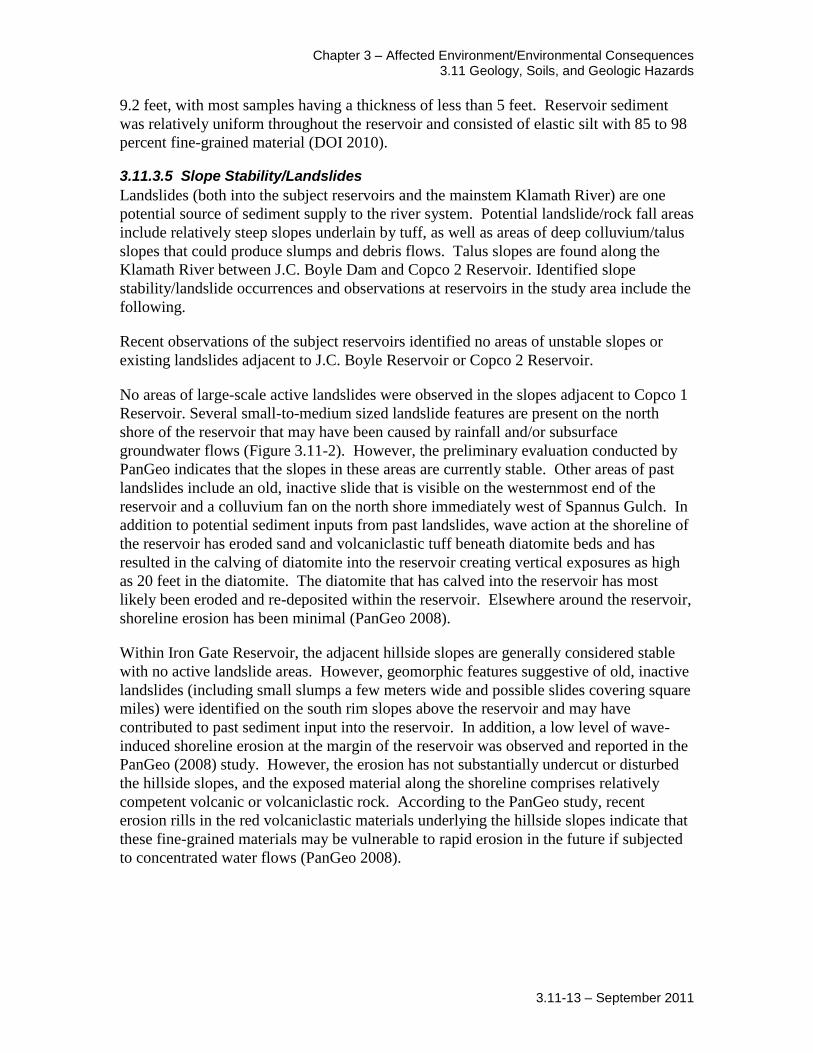
No areas of large-scale active landslides were observed in the slopes adjacent to Copco 1
Reservoir. Several small-to-medium sized landslide features are present on the north
shore of the reservoir that may have been caused by rainfall and/or subsurface
groundwater flows (Figure 3.11-2). However, the preliminary evaluation conducted by
PanGeo indicates that the slopes in these areas are currently stable. Other areas of past
landslides include an old, inactive slide that is visible on the westernmost end of the
reservoir and a colluvium fan on the north shore immediately west of Spannus Gulch. In
addition to potential sediment inputs from past landslides, wave action at the shoreline of
the reservoir has eroded sand and volcaniclastic tuff beneath diatomite beds and has
resulted in the calving of diatomite into the reservoir creating vertical exposures as high
as 20 feet in the diatomite. The diatomite that has calved into the reservoir has most
likely been eroded and re-deposited within the reservoir. Elsewhere around the reservoir,
shoreline erosion has been minimal (PanGeo 2008).
Within Iron Gate Reservoir, the adjacent hillside slopes are generally considered stable
with no active landslide areas. However, geomorphic features suggestive of old, inactive
landslides (including small slumps a few meters wide and possible slides covering square
miles) were identified on the south rim slopes above the reservoir and may have
contributed to past sediment input into the reservoir. In addition, a low level of wave-
induced shoreline erosion at the margin of the reservoir was observed and reported in the
PanGeo (2008) study. However, the erosion has not substantially undercut or disturbed
the hillside slopes, and the exposed material along the shoreline comprises relatively
competent volcanic or volcaniclastic rock. According to the PanGeo study, recent
erosion rills in the red volcaniclastic materials underlying the hillside slopes indicate that
these fine-grained materials may be vulnerable to rapid erosion in the future if subjected
to concentrated water flows (PanGeo 2008).

Klamath Facilities Removal EIS/EIR Public Draft
3.11-14 – September 2011
Figure 3.11-2. Existing Potential Landslide Areas

Chapter 3 – Affected Environment/Environmental Consequences 3.11 Geology, Soils, and Geologic Hazards
3.11-15 – September 2011
Potential landslide/rockfall areas downstream from the Four Facilities include all steep
slopes underlain by tuff, as well as areas of deep colluvium/talus slopes that could
produce slumps and debris. Talus slopes are found through the Klamath River Canyon
(the stretch of river between J.C. Boyle and Copco 2 Dams). Continuous creep of talus
and rapid rockfalls are likely on and near talus slopes, and the potential exists for slow-to-
moderate migration of some of the large slides. Landsliding is also prevalent in the
Franciscan geology of the lower Klamath River watershed and along tributary watersheds
within the Klamath Mountain geomorphic province, such as the Salmon River (FERC
2007). As discussed above when describing the geomorphology of the river, existing
landslide areas are present downstream from the Scott River confluence.
Soils Upper Klamath River
Soils in the vicinity of the Upper Klamath River, surrounding J.C. Boyle Reservoir, and
along the river south to the Oregon-California border generally consist of lacustrine and
alluvial clay, silt, fine-grained sand and peat (Priest et al 2008). The primary soil
association along both sides of the river is Skookum-rock outcrop-Rubble land complex
with 35 to 70 percent slopes. Immediately surrounding Keno Impoundment, soils consist
of the Bly-Royst complex (Natural Resources Conservation Service [NRCS] 2005).
Klamath Hydroelectric Project
Soils along the Klamath River and on reaches between the subject reservoirs are less
homogenous in California. However, the various soil formations can be grouped
generally into those on steeper slopes, floodplain or terrace surfaces, or directly along the
river itself. The soils on steeper slopes are shallow to moderately deep and comprise a
7-8 inch surface horizon of gravelly loam, and an underlying horizon of gravelly, clayey
loam. Floodplain and terrace soils are comprised of deep, well-drained alluvium and
colluvium. Directly along the river, soils are comprised of unconsolidated alluvium,
colluvium, and fluvial deposits. These geologically recent deposits consist of
unconsolidated sand, silt, and gravels deposited by water or erosion (FERC 2007).
Below Iron Gate Dam
Soils along the Klamath River below Iron Gate Dam are generally composed of
associations consisting of gravelly clay loam and gravelly sandy loam (Holland-Clallam,
Skalan, Weitchpec, and Lithic Mollic Dubakella associations). Soils on steeper slopes
are deeper (22 to 60 inches) than those on less steep slopes and along the floodplain.
These soil associations are all classified as well-drained, with low to no flooding
frequency or ability for ponding water. Soils directly along the river in floodplain areas
are comprised of alluvial deposits consisting of sand and gravels (NRCS 2007 and 2008).
3.11.3.6 Faults and Seismicity
Review of available fault and earthquake epicenter maps for northern California and
southern Oregon show no fault lines or earthquake epicenters beneath Iron Gate Dam or
the Copco Dams and Reservoirs. However, volcanic vents occur very close to the two
Copco Dams. Faults exist beneath the J.C. Boyle Dam and Reservoir. However, these
faults have not moved within the past 1.5 million years and, therefore, are termed not

Klamath Facilities Removal EIS/EIR Public Draft
3.11-16 – September 2011
active (Personius et al. 2003). No earthquake epicenters are mapped beneath the
J.C. Boyle Reservoir, but one of the largest earthquakes ever recorded in Oregon
occurred in 1993 in and around the Klamath Falls areas approximately 15 miles north of
the J.C. Boyle Reservoir.
In California, the nearest active fault to the Four Facilities is the Meiss Lake fault,
approximately five miles east of the Klamath River near the California/Oregon Stateline
in Siskiyou County. The next nearest California-zoned active fault in relation to the Four
Facilities is the Mahogany Mountain fault zone approximately 6 miles east (Jennings and
Bryant 2010).
3.11.3.7 Volcanic Activity and Associated Strata
The High Cascades geomorphic province consists of a narrow band of shield volcanoes
built on top of the eastern portion of the Western Cascades strata. The High Cascades are
represented in the vicinity of the Four Facilities by the extinct cones of Eagle Rock
Mountain to the south of the Klamath River valley, the Secret Spring Mountain and
McGavin Peak to the southeast, and Mount Shasta to the Northwest. There are also a
series of basaltic volcanoes extending northward into Oregon towards Klamath Falls,
which have been dissected by subsequent basin and range block faulting (PanGeo 2008).
In addition to the large shield volcanoes with their multiple eruptive events, numerous
smaller vents and volcanoes are present in the area. The majority of the volcanism in the
Upper Klamath Basin consists of single events from a given vent and most of the smaller
explosive cones are formed from the interaction of flow material intersecting ground
water (hydrovolcanic events). High Cascades volcanism continues to the present day
(PanGeo 2008). During the last 10,000 years, Mount Shasta has erupted once per 800
year period, and once per 600 years over the last 4,500 years. The last known eruption
was radiocarbon dated to approximately 200 years ago (Miller 1980).
The rocks in the vicinity of the Four Facilities range in age from roughly 45 million years
old up to the present. Copco and Iron Gate Dams are in the Western Cascades. The
volcanic activity that formed the Western Cascades is thought to have started between 42
and 45 million years ago (Eocene) and continued until approximately 10 and 5 million
years ago. Over time, the main area of volcanic activity shifted eastward and narrowed.
The intensity of volcanism also diminished and erosion activity erased much of the
evidence of the original volcanoes. Estimates of the thickness of the Western Cascades
strata range from between 12,000 and 15,000 feet to greater than 20,000 feet (PanGeo
2008).
In the vicinity of Copco Reservoir, up to half of the Western Cascade strata are exposed
in the Klamath River Canyon as a result of river down cutting. In this exposure, the
Western Cascade strata are comprised of inter-bedded tuffs, ash, and lava flows dipping
to the east at approximately 25 degrees. The eastern dipping strata of the Western
Cascade is overlain by the nearly flat lying High Cascade strata composed of younger
Pliocene lava flows with a thickness of up to 500 feet. The inter-bedded strata of the
Western Cascade can form aquifers and when coupled with a remnant volcanic heat

Chapter 3 – Affected Environment/Environmental Consequences 3.11 Geology, Soils, and Geologic Hazards
3.11-17 – September 2011
source and sealed by overlying High Cascade lava flows, geothermal reservoirs can form
(Hammond 1983).
3.11.4 Environmental Consequences
3.11.4.1 Environmental Effects Determination Methods
The environmental consequences of the alternatives focus on changes to geomorphology
and sediment transport. This analysis discusses potential increases in geologic hazards
downstream from the reservoirs, as well as potential increases in erosion in the Upper
Klamath Basin under implementation of each of the alternatives.
DOI used the Sedimentation and River Hydraulics-One Dimension Version 2.4 sediment
transport model to analyze the potential transport of reservoir sediment downstream
based on different drawdown scenarios. The analysis below uses the results of DOI’s
sediment transport modeling to evaluate changes in downstream sediment regimes and
the effect of the changes on shoreline geology downstream from the reservoirs. The
analysis also qualitatively analyzes the potential for local sedimentation in eddies and
other low gradient zones in the Klamath River channel.
3.11.4.2 Significance Criteria
For the purposes of this EIS/EIR, impacts would be significant if they would result in the
following:
Substantial soil erosion into reservoir areas or along the Klamath River.
Cause new or exacerbate existing landslides along the banks of the reservoirs.
Incomplete flushing of sediment with substantial deposition downstream, which
adversely affects other associated resources (i.e., Water Quality, Fish Resources,
Mollusks, and Benthic Invertebrates).
Exposure of people or structures to adverse effects resulting from rupture of a
known earthquake fault, strong seismic ground shaking, or volcanic activity.
Remove access to diatomite beds for extraction.
3.11.4.3 Effects Determinations
Alternative 1: No Action/No Project
Under the No Action/No Project Alternative, J.C. Boyle, Iron Gate, and Copco 1
Reservoirs would continue to trap sediment at rates similar to historical rates. Based on
historic sediment trapping rates and sediment levels in each reservoir, it is estimated that
approximately 23.5 million yd3
of sediment would be stored behind the dams in 50 years
time (i.e., by 2061). Studies conducted by DOI indicate that the trapping efficiency of
J.C. Boyle Dam may decrease slightly as the reservoir capacity decreases but the rate at
which this may happen is uncertain and is not likely to change substantially over the next
50 years (DOI 2011a). It is likely that after the storage capacity reduces to a certain
level, sedimentation in the reservoirs would stop and sediment would begin to pass
through the reservoir pools and be transported downstream. Table 3.11-3 summarizes the

Klamath Facilities Removal EIS/EIR Public Draft
3.11-18 – September 2011
current estimated volume of sediment in each reservoir, the respective sediment trapping
rate, and the anticipated sediment volume in each reservoir in 50 years.
No future substantial erosion or landslides are expected to occur downstream from any of
the Four Facilities under the No Action/No Project Alternative. As described in Section
3.11.3 (Existing Conditions/Affected Environment), river elevation downstream from the
dams is primarily controlled by large boulders and bedrock, and only limited adjustment
is possible. There would be no change from existing conditions as a result of the No
Action/ No Project.
Table 3.11-3. Estimated Future Sediment Volume in Reservoirs under the No Action/No Project Alternative
Reservoir
Original Storage Capacity (acre-ft)
Current Sediment
Volume (yd3)
Sedimentation Rate (yd
3/yr)
2061 Sediment Volume (yd
3)
% Reduction in Storage Capacity
J.C. Boyle 3,495 1,000,000 19,600 2,020,000 36
Copco 1 46,867 7,400,000 81,300 11,600,000 15
Copco 2 73 0 0 0 0
Iron Gate 58,794 4,700,000 100,000 9,900,000 10
Total 109,229 13,100,000 201,000 23,500,000 13
Source: DOI 2011a
Key:
yd3: cubic yards
yd3/year: cubic yards per year
lb/ft: pounds per foot
Under the No Action/No Project Alternative, Copco 1 Reservoir would continue to
prohibit access to diatomite beds. Diatomite beds are at the southern shore of the
reservoir near the dam and are even with or extending up to 20 feet above the reservoir
surface. Wave action at the shoreline has eroded the diatomite. Because of their location
in the reservoir and existing erosion, diatomite resources are currently inaccessible for
extraction purposes. There would be no change to the existing conditions of diatomite
beds under the No Action/No Project Alternative because the resources would
continue to be inaccessible.
Alternative 2: Full Facilities Removal of Four Dams (Proposed Action)
Soil disturbance associated with heavy vehicle use, excavation, and grading could result
in erosion during removal activities. As described in the Affected Environment, shoreline
erosion is generally not a substantial factor affecting the Iron Gate and J.C. Boyle
Reservoirs, although it is an issue at Copco 1 Reservoir, where eroded sand and
volcaniclastic tuff has resulted in the subsequent calving of diatomite into the reservoir.
This existing erosion is caused by wave action in the reservoir (PanGeo 2008). Soil
disturbance associated with heavy vehicle use, excavation, and grading could result in

Chapter 3 – Affected Environment/Environmental Consequences 3.11 Geology, Soils, and Geologic Hazards
3.11-19 – September 2011
erosion during removal activities at Iron Gate and J.C. Boyle Reservoirs and could
exacerbate existing erosion at Copco 1 Reservoir. Prior to demolition, coverage under
the General Stormwater National Pollution Discharge Elimination System (NPDES)
Permit for Construction Activities in both Oregon and California would be required as
per Section 402 of the Clean Water Act. Coverage under this permit requires the
development and implementation of an Erosion and Sediment Control Plan prior to
deconstruction that describes best management practices (BMPs) to prevent erosion
during demolition activities. Implementation of these BMPs would minimize the
potential for erosion into the reservoir areas. Erosion impacts into the reservoir areas
would be short-term and less than significant.
Drawdown of the four reservoirs could cause instability along the banks of the
reservoirs. Reservoir drawdown proposed under the Proposed Action could trigger new
landslides or exacerbate existing landslides along the banks of reservoirs in the project
area. Slumping and some mudflows are expected to occur from reservoir drawdown
actions. Slopes with inclinations from 18 to 40 degrees would be most susceptible to
slumping. The amount of slumping that could occur would be dependent on the
drawdown rate (slower drawdown rates would result in fewer slides and less slumping).
The slumping that would occur is part of the design, in that it would remove the unstable
portions of the newly-exposed slopes while there is sufficient flow in the river to
transport the material downstream. The PanGeo (2008) study, which was described in
Section 3.11.3 (Existing Conditions/Affected Environment), concluded that the hillside
slopes below the pool levels behind Iron Gate, Copco 1, and J.C. Boyle Dams would
likely perform relatively well and remain stable during drawdown activities. In addition,
no large-scale landslides are anticipated in newly exposed areas and any new slides that
may develop would most likely be below the existing water level in the reservoirs,
although such slides could create higher deposition on the terraces above the newly
formed river channel. These potential landslide impacts would be short-term and less
than significant.
Reservoir drawdown at Copco 1 would reduce the potential for erosion and future
landslides. Because existing erosion at Copco 1 Reservoir is largely the result of wave
action, emptying the reservoir would remove this source of shoreline erosion. As noted
above, no large-scale landslides are anticipated in newly exposed areas during drawdown.
In the long-term with implementation of reservoir restoration actions including hydro
seeding, landslides and erosion would not be expected at a higher frequency or of a larger
size than what is currently contributed from the slopes adjacent to the reservoirs. Thus,
long-term impacts with regards to erosion and potential landslides at Copco 1
Reservoir would be less than significant.
Drawdown of reservoirs could cause bank erosion downstream. The drawdown of the
four reservoirs would occur simultaneously beginning in January 2020. Based on the
current project schedule and drawdown rate restrictions, the controlled released would
maintain the minimum required flows in each reach. Section 3.6, Flood Hydrology,
discusses historic flow rates and discharge statistics for each of the reservoirs. The
proposed drawdown rates are consistent with the historic discharge rates from the

Klamath Facilities Removal EIS/EIR Public Draft
3.11-20 – September 2011
reservoirs and would be adjusted depending on the water year; therefore, flow rates
downstream from the dams are not anticipated to increase substantially above median
historic rates, if at all (discharges from the reservoirs would be similar to seasonal
10-year flood flows from the reservoirs).
Although some landslides and erosive areas have been identified in the lower river, based
on the expected flow rates that are similar to existing flow rates, substantial amounts of
additional erosion are not expected to occur downstream from any of the dams as a result
of reservoir drawdown. Any erosion downstream would be minimal; these impacts
would be short-term and less than significant.
Drawdown of reservoirs and release of sediment would result in short-term increases in
sedimentation in slow-moving eddies and pools downstream from the reservoirs and in
the Klamath River estuary. During reservoir drawdown in 2020, the sediment behind the
four dams would be released downstream. DOI conducted modeling of the reservoir
drawdown and erosion of reservoir sediment. The drawdown of Iron Gate Reservoir
would ultimately control sediment released from Copco 1 and 2, and J.C. Boyle
Reservoirs due to its location furthest downstream. Since all reservoirs would be drawn
down concurrently, sediment released from the upstream reservoirs would remain
suspended and is not anticipated to settle within Iron Gate Reservoir. However, the
released sediment would likely exceed the carrying capacity of the river during some
water year types, and would result in sedimentation and particle settling downstream in
eddies, pools, and the Klamath River estuary. The potential for deposition downstream is
dependent on particle size and the water year type in 2020, and subsequent years. In
general, sediment transport capacity in a dry year would be small and any downstream
sediment deposition would stay in place, until the next substantial series of storms or
snowmelt came. In contrast, during a wet year, suspended sediment would be more
likely to be carried through the river to the ocean without substantial settling and
deposition4.
To determine how much sediment would be moved through the river, a study compared
the settling velocity5 of the reservoir sediment to the velocity profiles downstream from
Iron Gate Dam. Based on the slope of the river and composition of river substrate
downstream from the dam, as well as the daily average discharge (approximately
3,000 cfs), the study found that particles with a settling velocity less than 0.23 ft/s have
the potential to be mobile as suspended sediment. This corresponds to sediment particles
finer than 0.68 mm (coarse sand) (Table 3.11-4; Stillwater Sciences 2004).
4 Representative dry, median, and wet water years were defined as the 90%, 50%, and 10% exceedance
flow volumes for the period from March to June at Keno on the Klamath River. The dry, median, and wet water years were 2001, 1976, and 1984, respectively.
5 Settling velocity is the rate at which particles suspended in a fluid subside and are deposited. Settling velocity is dependent on gravitational force, the type of fluid, how smoothly and quickly the fluid is flowing, and the particle size and shape.

Chapter 3 – Affected Environment/Environmental Consequences 3.11 Geology, Soils, and Geologic Hazards
3.11-21 – September 2011
Table 3.11-4. Estimated Particle Sizes that would be Suspended at Average and Maximum Daily Discharge Rates
Discharge 3,000 cfs 7,000 cfs
Shear velocity 0.58 ft/s 0.76 ft/s
Maximum settling velocity for suspension
0.23 ft/s 0.34 ft/s
Corresponding particle size 0.42 mm 0.68 mm
Corresponding size class Medium sand Coarse sand
Source: Stillwater Sciences 2004
Key:
cfs: cubic feet per second (discharge rate)
ft/s: feet per second
mm: millimeters
Modeling conducted by DOI analyzed the deposition rate of the released sediment
downstream of Iron Gate Dam for a two year period following commencement of
drawdown activities. Three types of water year scenarios were analyzed (dry, wet, and
average). The results of the modeling found that under all three water year types, fine
sediment would be transported downstream as suspended sediment (DOI 2011a). As
described in the Affected Environment, sediment sampling in the reservoirs has indicated
that, with the exception of Copco 1, the majority of sediment is composed of fine-grained
elastic silt. Therefore, it is expected that deposition would occur in pools or along
vegetated area during low-flow periods, but that the deposition would be flushed
downstream during high-flow events. Any settling or sedimentation of fine sediment in
eddies or pools is expected to be minimal and short-lived. Further, as described in
Section 3.11.3.2, Geomorphology, there is no sandbar within the mouth of the Klamath
River itself; rather the sandbar is located offshore. As a result, the majority of the
suspended sediment load from the river is carried out to sea and does not remain in the
estuary itself. The amount of sediment delivered to the ocean in a given year is entirely
dependent on the water year type.
In a wet year, the additional sediment load from removal of the dams would be relatively
small compared to a dry year. However, the amount of sediment delivered to the ocean
following removal of the dams is still expected to be less than the average annual supply.
The only reservoir material that would be transported to the estuary would be fine
material which is not expected to deposit at the estuary (DOI 2011a). Downstream of Iron
Gate Dam, a substantial increase in sand content is expected in the reach between the
dam and Bogus Creek. Sand is expected to increase by up to 40 percent in the month
immediately following reservoir drawdown. Under a wet year scenario, the sand would
decrease to below 20 percent within a year; however, under a median or dry scenario, a
subsequent wet year would be required to flush the sand material from the bed.
Downstream of Bogus Creek, it is expected that sand may take longer to be flushed
downstream and under dry or median year scenarios it could take 5 to 6 years for sand in
the bed to return to equilibrium levels between Bogus Creek and Willow Creek and up to
10 years between Willow Creek and Cottonwood Creek (DOI 2011a).

Klamath Facilities Removal EIS/EIR Public Draft
3.11-22 – September 2011
Particles greater than coarse sand would be deposited in eddies and slow-moving pools
downstream following dam removal, primarily between Iron Gate Dam and Cottonwood
Creek. Under the wet year scenarios, the coarse sediment load would take approximately
15 months (until March 2021) to be completely flushed downstream and into the Pacific
Ocean. Although the coarse material would deposit temporarily in slow-moving portions
of the river, there would be no substantial change in river bed elevation. In contrast, if
drawdown were to occur during a dry year, modeling indicates that substantial deposition
would still be present between Iron Gate Dam and Shasta River at the end of the two year
modeling period. However, the model results indicated that under all three water type
scenarios, the maximum thickness of sediment deposition immediately downstream from
Iron Gate Dam would be less than 2 feet (DOI 2011a). Further, when considered in
comparison to sediment loading from other existing sources along the Klamath River
(refer to Table 3.11-1 above), the magnitude of the anticipated sediment release from
behind the reservoirs is relatively small. A study by Stillwater Sciences (2010) assessed
the sediment loading to the Klamath River based on the cumulative sediment load already
contributed by tributaries to the river. The numeric modeling predicted high, medium,
and low values for reservoir sediment release based on different hydrologic scenarios and
the assumed dimensions of the new channel that would be created within the former
reservoirs. The model predicted that the median fine-grained and total sediment load
released by dam removal would not be substantially more than the cumulative average
annual fine-grained and total sediment delivery between Iron Gate Dam and the Scott
River. The model also predicted that the overall contribution of reservoir sediment to the
river system decreased substantially downstream (Stillwater Sciences 2010).
The total sediment transport capacity of the river was not assessed in the Stillwater
Sciences Study, and as such it does not demonstrate that the additional sediment load
from dam removal would not deposit in the Klamath River. Rather, the findings of the
analysis suggest that the release of sediment downstream during reservoir drawdown
would not exceed the existing sediment load added by any tributary, and as such, the
transport capacity of the river may be sufficient to transport the additional load,
particularly since the river is supply-limited in regards to fine-grained material and sand.
Sedimentation impacts are therefore expected to be short-term. The significance of
impacts with regard to sediment deposition is dependent on the corresponding impacts of
the deposition on aquatic biology (see Section 3.3, Aquatic Resources) and water quality
(see Section 3.2, Water Quality). As discussed in these sections, sediment deposition
would not result in substantial adverse impacts and no mitigation measures are indicated.
Therefore, impacts with regard to sediment deposition downstream of Iron Gate
Dam would be short-term and less than significant.
Drawdown of reservoirs could result in changes to seismic or volcanic activity. As
described in the Affected Environment, although the Four Facilities are in a historically
seismic active area, the nearest active fault is approximately five miles from the dams
proposed for removal. It is noted that faults do exist under J.C. Boyle Reservoir.
However, these faults are reported not to have moved within the past 1.5 million years
and, therefore, are termed as not active (Personius et al. 2003). Under the Proposed

Chapter 3 – Affected Environment/Environmental Consequences 3.11 Geology, Soils, and Geologic Hazards
3.11-23 – September 2011
Action, the Four Facilities would be removed within a one year period between
November 2019 and December 2020. Sediment currently held behind the dams would be
released during the same year period. Although there is substantial literature regarding
the inducement of seismicity by reservoir filling, little is documented with regard to the
drawdown of reservoirs of this size. Consequently, it is not expected that reservoir
draining would cause such actions. Reservoir draining is also not expected to cause
volcanic activity due to the distance from volcanic hazards (e.g., Mount Shasta). Further,
following removal of the Four Facilities, no new structures would be constructed in the
project area. Therefore, the impacts with regard to increased risk of hazards
associated with ground rupture or seismic shaking during reservoir drawdown
would be less than significant.
Following dam removal, reservoir sediment remaining could result in changes in the
amount of erosion in the river channel. DOI 2011a, using representative dry, median,
and wet years from the hydrologic period of record between 1961 and 2008, indicated
that if dam removal occurred during a wet year, up to 56 percent of the reservoir
sediment would be eroded. In contrast, if removal were to occur during a dry year, about
38 percent of the sediment would be eroded. The remaining sediment would be expected
to remain on the reservoir terraces and dry. However, as discussed in Section 3.11.3.4
(Reservoir Substrate Composition), sediment in the reservoirs is fairly shallow (4-8 feet
thick). Therefore, following erosion of the sediment during dam removal, the remaining
sediment would be much more like a landscape veneer than a wedge along the newly
formed river channel.
Field tests (DOI 2011a) were conducted to determine the characteristics of dried reservoir
sediment. Table 3.11-5 shows a comparison of the depth of wet and dry sediment
samples. As the table shows, the desiccated depth of the sample was about 60 percent of
the initial depth. Deep cracks developed in the soil and the sample pulled away from the
container edges. The estimated reduction in volume of the sample was about 66 percent.
The porosity changed from 0.82 to approximately 0.46 and the bulk density increased
from 29.5 pounds per cubic foot (lb/ft3) to approximately 87 lb/ft
3. The bulk density of
the dried reservoir sediment would be similar to that of the pre-dam sediment in the
reservoir area. Erosion tests conducted by the Agricultural Research Service (Simon and
Bell 2010) found that the erosion resistance of dried sediment was more than 10 times
higher than the resistance of wet sediment. Therefore, minimal erosion is expected
following completion of reservoir drawdown and dam removal activities. The impact of
dam removal on erosion would be long-term but less than significant.
Table 3.11-5. Comparison of Wet and Dry Reservoir Samples
Container Initial Thickness
(inches) Final Thickness
(inches) % of Original
Thickness
1 7.00 4.25 60
2 7.88 4.63 59
3 4.50 2.75 61
Source: DOI 2011a.

Klamath Facilities Removal EIS/EIR Public Draft
3.11-24 – September 2011
Following dam removal, reservoir sediments remaining could result in changes to
downstream sediment deposition. As discussed above, once dry, the remaining sediment
in the former reservoir areas would be unlikely to erode downstream except during storm
and other high-flow events. As previously discussed, the Klamath River is supply-
limited for fine-grained material. Further, based on the estimated settling velocity of the
remaining sediment and average flows during wet years and storm events, it is expected
that any eroded sediment would be transported as suspended sediment flushed
downstream. Therefore, impacts of dam removal on downstream sediment supply
would be long-term, but less than significant.
Following dam removal, the reservoir sediment remaining would dry and could affect
restoration activities and/or future road construction activities. As discussed previously,
following dam removal an estimated 44 to 62 percent of the sediment in the reservoirs
would remain and is expected to settle on the terraces of the new river channel. Initial
sampling conducted on the sediment indicates that once dry, it has a tendency to crack
and substantially decrease in porosity. This characteristic would not necessarily limit the
range of restoration activities but could limit future construction activities (e.g., access
road construction, recreation facilities) that could occur in the former reservoir area.
Limitations on future construction due to sediment properties are analyzed in the
Reservoir Restoration Study (DOI 2011b). The potential limiting characteristics of the
remaining sediment in the reservoirs would be considered a significant impact, but
mitigation measure GEO-1 would reduce these impacts to less than significant.
Following dam removal, diatomite beds near Copco Reservoir would be inaccessible.
Under Proposed Action, the ownership of the reservoir land would be transferred to the
Dam Removal Entity (DRE). After transfer it is likely that the DRE would not allow
access to the diatomite beds for commercial extraction. Additionally, any paleontological
resources potentially contained within the diatomite beds would remain inaccessible.
Therefore, there would be no change from existing conditions for diatomite beds
under the Proposed Action because the resources would continue to be inaccessible.
Following reservoir drawdown, the Yreka water supply pipeline would be relocated. The
existing water supply pipeline for the City of Yreka passes under the Iron Gate Reservoir
and would have to be relocated prior to the decommissioning of the reservoir to prevent
damage from deconstruction activities or increased water velocities once the reservoir has
been drawn down. The pipeline would either be suspended from a pipe bridge across the
river near its current location, or rerouted along the underside of the Lakeview Bridge
just downstream of Iron Gate Dam. The construction of a pipe bridge would not affect
sediment supplies, contribute substantially to erosion, or expose people or populations to
geologic hazards. Placing the pipe along the Lakeview Bridge would have less impact
than the construction associated with the pipe bridge. Therefore, there would be no
change in the existing conditions of geology, soils, or geologic hazards as a result of
the pipeline relocation.

Chapter 3 – Affected Environment/Environmental Consequences 3.11 Geology, Soils, and Geologic Hazards
3.11-25 – September 2011
Following reservoir drawdown, recreational facilities currently located on the banks of
the existing reservoirs would be removed. The existing recreational facilities provide
camping and boating access for recreational users of the reservoirs. Once the reservoirs
are drawn down, these facilities would be removed. The removal of the recreational
facilities would not affect sediment supplies, contribute substantially to erosion, or
expose people or populations to geologic hazards. Therefore, there would be no change
in the existing conditions of geology, soils, or geologic hazards as a result of the
recreational facilities.
Keno Transfer
The Keno Transfer could have adverse effects to geology, soils, or geologic hazards. The
Keno Transfer is a transfer of title for the Keno Facility from PacifiCorp to the DOI.
This transfer would not result in the generation of new impacts on geology and soils
compared with existing facility operations. Following transfer of title, DOI would operate
Keno in compliance with applicable law and would provide water levels upstream of
Keno Dam for diversion and canal maintenance consistent with agreements and historic
practice (Klamath Hydroelectric Settlement Agreement [KHSA] Section
7.5.4). Therefore, the implementation of the Keno Transfer would result in no
change from existing conditions.
East and West Side Facilities
The decommissioning of the East and West Side Facilities could have adverse effects to
geology, soils, or geologic hazards. Decommissioning of the East and West Side canals
and hydropower facilities of the Link River Dam by PacifiCorp as a part of the KHSA
will redirect water flows currently diverted at Link River Dam into the two canals, back
in to Link River. Redirection of flows would not change sedimentation rates in Upper
Klamath Lake and the action would have no impact to geology and soils. Therefore, the
decommissioning of the East and West Side Facilities would result in no change
from existing conditions.
KBRA
The KBRA has one element that could result in changes to geology, soils and geologic
hazards:
Phases I and II Fisheries Restoration Plans
Phases 1 and II Fisheries Restoration Plans
Implementation of the Phase I Fisheries Restoration Plan could result in construction
related sediment erosion. Several ongoing resource management actions related to
fishery health and water quality may be amplified under the Phase I Plan (Section
2.4.3.9). The following sections describe the ongoing actions and types of new programs
that could be implemented, and their anticipated short-term and long-term effects at a
programmatic level.

Klamath Facilities Removal EIS/EIR Public Draft
3.11-26 – September 2011
Floodplain Rehabilitation
Floodplain rehabilitation work would include activities to improve or restore connections
between channels and floodplains to create and maintain off-channel habitat accessible to
overwintering juvenile salmonids. In the short-term (i.e., during construction activities),
these activities may involve the use of backhoe equipment to dig channels,
remove/reposition levees and dikes, and conduct mechanical planting. These
construction activities could result in increased erosion as a result of ground disturbance.
In the long term, increased seasonal off-channel habitat, wetland restoration, and levee
setbacks, may reduce sediment erosion due as a result of potential reduction in flood flow
velocity in some flood events through the reestablishment of floodplains.
Woody Debris Placement
In-stream and streambank large woody debris placement may include both mobile wood
(i.e., unanchored) and complex stationary (i.e., anchored) structures and may be used to
create off-channel fish habitat or provide cover in deeper pools. In the short term, these
activities may involve the use of construction equipment to place large wood in the
stream channel or along banks. These activities could result in increased erosion as a
result of ground disturbance in construction staging areas and on the stream banks and in
the streambeds.
Fish Passage Correction
Correction of fish passage issues throughout the Klamath Basin may include culvert
upgrades or replacement to meet current fish passage standards and correction of other
fish blockages to restore access to new or historical habitats. In the short term, these
activities may include in-channel construction of culverts through existing roadways,
which could result in increased erosion as a result of ground and riverbank disturbance.
Mechanical Thinning and Prescribed Burning
Mechanical thinning and prescribed burning of upland forest areas may be used to mimic
some of the functions and characteristics historically provided by a natural fire regime.
In the short term, thinning and prescribed burning could increase sediment erosion
through reduction in groundcover. In the long term, thinning and prescribed burning may
reduce the potential for catastrophic fires and the associated high rates of erosion and
nutrient release (primarily phosphorus) to tributaries and the main-stem Klamath River.
Road Decommissioning
Road decommissioning would reduce road densities in areas with a high potential for
slope failure and would stabilize hillsides. In the short-term these construction activities
could result in increased erosion as a result of ground disturbance. In the long-term, these
activities would decrease the incidence of road failure and would minimize a source of
landslide and erosion generated input of sediment into water bodies in the Klamath Basin.
Gravel Augmentation
Gravel augmentation involves the direct placement of spawning size gravel into the
stream channel. Gravel augmentation can increase spawning habitat in systems by
increasing the amount of area with suitable substrate. Gravel augmentation activities

Chapter 3 – Affected Environment/Environmental Consequences 3.11 Geology, Soils, and Geologic Hazards
3.11-27 – September 2011
may involve transportation of gravel from an off-site source using dump trucks and
placement in the stream using backhoes. In the short term, this could introduce fine
sediments into the river channel. Depending on the water year during which gravel
augmentation takes place, this sediment could result in temporary deposition
downstream.
Summary
Construction actions including the operation of construction equipment and the
associated soil disturbance could result in erosion into the active river channel and could
cause new or exacerbate existing landslide areas. Additionally gravel augmentation could
result in temporary sediment transport and deposition downstream of the construction
site. Construction activities associated with the Restoration Plan would not occur in the
same location or at the same time as hydroelectric facility removal. Therefore, erosion
effects would not add to potential effects of dam removal activities. However, negative
short-term effects of increased sediment erosion, and landslides generated by the
restoration plan’s construction activities could occur, but would be reduced by
construction-related BMPs that would be implemented. Given implementation of
BMPs (see Appendix B), the short-term effects on sediment erosion and landslides
and would be less than significant. In the long-term, implementation of the Phase I
and II Fisheries Restoration Plans would be expected to generate a beneficial
reduction in sediment erosion through improved river channel stability, and
generate no change from existing conditions for landslides. Implementation of
specific plans and projects described in the KBRA will require future
environmental compliance as appropriate.
Alternative 3: Partial Facilities Removal of Four Dams
Under this alternative, short-term demolition activities and drawdown of reservoirs would
still occur; however, demolition would consist only of in-stream facilities and select
ancillary facilities. Impacts to soils and sediments would be the same as those described
for the Proposed Action.
Keno Transfer
The geology and soils impacts of the Keno Facility Transfer under the Partial Facilities
Removal of Four Dams Alternative would be the same as for the Proposed Action.
East and West Side Facility Decommissioning
The geology and soils impacts of the East and West Side Facility Decommissioning
under the Partial Facilities Removal of Four Dams Alternative would be the same as for
the Proposed Action.
KBRA
Under this alternative, the KBRA would be fully implemented; therefore, impacts to soils
and sediments would be the same as those described for the Proposed Action.
Alternative 4: Fish Passage at Four Dams
Short-term construction under the Fish Passage at Four Dams Alternative could change
erosion patterns. Under this alternative, no demolition of the Four Facilities would take

Klamath Facilities Removal EIS/EIR Public Draft
3.11-28 – September 2011
place; however, short-term construction activities would occur during installation of fish
passage at the four dams. The potential exists for short-term increases in erosion along
the banks of the reservoirs during construction activity. Prior to any construction,
coverage under General Stormwater Permits and the development and implementation of
Erosion and Sediment Control Plans would be required as per Section 402 of the Clean
Water Act. Accordingly, erosion impacts would be short-term and less than
significant.
Under the Fish Passage at Four Dams Alternative, J.C. Boyle, Iron Gate, and Copco 1
Reservoirs would continue to trap sediment at rates similar to historical rates. The
reservoir drawdown and sediment transport impacts described under the Proposed Action
would not occur. The reservoirs would continue trapping sediment and there would
be no change from existing conditions.
Under the Fish Passage at Four Dams Alternative, the Copco 1 Reservoir would
continue to prevent access to the diatomite beds. Diatomite resources and any associated
paleontological resources are currently inaccessible due to the presence of the Copco 1
Reservoir. There would be no change from existing conditions for the diatomite beds
because the resources would continue to be inaccessible.
Alternative 5: Fish Passage at J.C. Boyle and Copco 2, Remove Copco 1 and Iron Gate
Reservoir drawdown could cause instability along the banks of the reservoirs, reservoir
bank instability, and construction generated erosion. Under this alternative, only Iron
Gate and Copco 1 Dams would be removed and fish passage would be installed at Copco
2 and J.C. Boyle Dams. Impacts associated with short-term construction and demolition
activities would be as described for the Proposed Action. Impacts associated with
reservoir drawdown and sediment transport would be similar to the impacts
described for the Proposed Action. However, the magnitude of any impacts would
be less than described for the Proposed Action due to the retention of sediment
behind J.C. Boyle and Copco 2 Dams.
Following dam removal, the diatomite beds near Copco Reservoir would become more
accessible. Diatomite resources and any associated paleontological resources are
currently inaccessible due to the presence of the Copco 1 Reservoir. Therefore, there
would be no change from existing conditions for the diatomite beds because the
resources would continue to be inaccessible.
3.11.4.4 Mitigation Measures
Mitigation Measure by Consequences Summary
Mitigation Measure GEO-1 – Prior to commencing construction of new recreation
facilities or access roads in the former reservoir areas, geotechnical analysis of the
proposed site should be conducted by a qualified geologist to determine the limitations of
construction on the sediment. If geotechnical tests indicate that the sediment is not
suitable to accommodate the proposed activities, the site should be avoided or a sediment
removal or treatment plan should be developed and sediment should be removed prior to
beginning construction activities.

Chapter 3 – Affected Environment/Environmental Consequences 3.11 Geology, Soils, and Geologic Hazards
3.11-29 – September 2011
Effectiveness of Mitigation in Reducing Consequences
Implementation of Mitigation Measure GEO-1 would ensure that any remaining sediment
in the former reservoir areas are appropriately studied and dealt with prior to
construction, such that any future proposed activities do not result in significant erosion
or sedimentation downstream.
Agency Responsible for Mitigation Implementation
The Dam Removal Entity would be responsible for implementing mitigation measure
GEO-1.
Remaining Significant Impacts
Following implementation of GEO-1, no significant adverse impacts associated with
Geology and Soils are anticipated. If the deposition of reservoir sediment downstream
resulted in adverse impacts to fish habitat or habitat for other aquatic species, impacts
would be considered significant. The potential for such impacts and mitigation for them
have been addressed in the relevant chapters of this EIS/EIR.
Mitigation Measures Associated with Other Resource Areas
Several other mitigation measures require construction, including mitigation measures
H-2 (flood-proof structures), GW-1 (deepen or replace affected wells), WRWS-1 (modify
or screen affected water intakes), REC-1 (develop new recreational facilities and access
to river), TR-6 (assess and improve roads to carry construction loads), and TR-7 (assess
and improve bridges to carry construction loads). These measures could disturb soil
because of construction activities associated with heavy vehicle use, excavation, and
grading. Prior to demolition, coverage under the General Stormwater NPDES Permit for
Construction Activities in both Oregon and California would be required as per Section
402 of the Clean Water Act (refer to Section 3.2, Water Quality, for more information).
Coverage under this permit requires the development and implementation of an Erosion
and Sediment Control Plan for each reservoir area. Implementation of these plans would
minimize the potential for erosion during demolition activities. These impacts would be
short-term and less than significant.
3.11.5 References
California Department of Conservation. 2002. California Geomorphic Provinces.
California Geological Survey. Note 36.
California, State of. Public Resources Code. Division 2, Chapters 7.5 and 7.8. Available
at: http://www.leginfo.ca.gov/cgi-bin/calawquery?codesection=prc&codebody=&hits=20
Department of the Interior (DOI), Bureau of Reclamation (Reclamation). 2010. Klamath
River Sediment Sampling Program, Phase I – Geologic Investigations. September.
DOI, Reclamation. 2011a. Hydrology, Hydraulics and Sediment Transport Studies for the
Secretary’s Determination on Klamath River Dam Removal and Basin Restoration,
Klamath River, Oregon and California. Prepared for Mid-Pacific Region, Technical
Report No. SRH-2011-02, Technical Service Center, Denver, CO.

Klamath Facilities Removal EIS/EIR Public Draft
3.11-30 – September 2011
DOI, Reclamation. 2011b. Reservoir Area Management Plan for the Secretary’s
Determination on Klamath River Dam Removal and Basin Restoration, Technical Report
No. SRH-2011-19. Prepared for Mid-Pacific Region, U.S. DOI, Bureau of Reclamation,
Technical Service Center, Denver, CO.
Federal Energy Regulatory Commission (FERC). 2007. Final Environmental Impact
Statement for Hydropower License, Klamath Hydroelectric Project, FERC Project No.
2082-027, FERC/EIS-0201F. Washington, DC, Federal Energy Regulatory Commission,
Office of Energy Projects, Division of Hydropower Licensing.
Gathard Engineering Consulting. 2006. Klamath River Dam and Sediment Investigation.
November 2006.
Hammond, P.E., 1983. Volcanic Formations Along the Klamath River Near COPCO
Lake. California Geology, A Publication of the California Division of Mines and
Geology. May 1983/Volume 36/Number 5, p 99-109.
Jayko, A.S., and Blake, M.C., Jr.1987. Geologic terranes of coastal northern California
and southern Oregon, in Schymiczek, Herman, and Suchsland, Reinhard, eds., Tectonics,
sedimentation, and evolution of the Eel River and associated coastal basins of northern
California: Bakersfield, San Joaquin Geological Society Miscellaneous Publication 37, p.
1-12.
Jennings, C.W., and Bryant, W.A. 2010. Fault Activite Map of California: California
Geological Survey Geologic Data Map No. 6, map scale 1:750,000.
Miller, C. D. 1980. Potential Hazards from Future Eruptions in the Vicinity of Mount
Shasta Volcano, Northern California: U.S. Geological Survey Bulletin 1503, 43p.
Available at:
(http://vulcan.wr.usgs.gov/Volcanos/Shasta/Hazards/Bulletin1503/framework.html)
Natural Resources Conservation Service (NRCS). 2005. Jackson County Area, Parts of
Jackson and Klamath Counties (OR632). Version 2, December 15. Available at:
(http://websoilsurvey.nrcs.usda.gov/app/WebSoilSurvey.aspx).
NRCS. 2007. Klamath National Forest Area, Parts of Siskiyou County, California and
Jackson County, Oregon (CA 702), Version 2, May 10. Available at:
(http://websoilsurvey.nrcs.usda.gov/app/WebSoilSurvey.aspx).
NRCS. 2008. Six Rivers National Forest Area (CA 701). Version 3, September 29.
Available at: (http://websoilsurvey.nrcs.usda.gov/app/WebSoilSurvey.aspx).
Oregon, Department of Land Conservation and Development. 2001. Oregon’s Statewide
Planning Goals and Guidelines. March 12. Available at:
http://www.oregon.gov/LCD/docs/goals/compilation_of_statewide_planning_goals.pdf?g
a=t

Chapter 3 – Affected Environment/Environmental Consequences 3.11 Geology, Soils, and Geologic Hazards
3.11-31 – September 2011
Oregon, State of. Oregon Revised Statues -2009 Edition. Available at:
http://www.leg.state.or.us/ors/home.html.
PanGeo. 2008. Geotechnical Report – Klamath River Dam Removal Project, Oregon and
California. Prepared for the Coastal Conservancy. August.
Personius, S.F., R.L. Dart, L.A. Bradley, and K.M. Haller. 2003. Map and Data for
Quaternary Faults and Folds in Oregon. U.S. Geological Survey Open-File Report 03-
095. Version 1.1. Available at http://pubs.usgs.gov/of/2003/ofr-03-095/.
Priest, G.R., F.R. Hladkey, and R.B. Murray. 2008. Geologic Map of the Klamath Falls
Area, Klamath County, Oregon. Oregon Department of Geology and Minerals.
Simon, A. R. Thomas, and R.B. Bell. 2010. Erodibility Characteristics of Bottom
Deposits from Three Klamath River Reservoirs, California and Oregon.
Siskiyou County. 1975. Siskiyou County General Plan – Seismic Safety and Safety
Element. Siskiyou County Planning Department. June.
Siskiyou County. 1980. Siskiyou County General Plan – Land Use and Circulation
Element. Siskiyou County Planning Commission. October.
Stillwater Sciences. 2004. A Preliminary Evaluation of the Potential Downstream
Sediment Deposition Following the Removal of Iron Gate, Copco, and J.C. Boyle Dams,
Klamath River, California. Prepared for American Rivers. May.
Stillwater Sciences. 2008. Technical Report – Klamath River Dam Removal Study:
Sediment Transport DREAM-1 Simulation. Prepared for the Coastal Conservancy.
October.
Stillwater Sciences. 2010. Anticipated sediment release from Klamath River Dam
removal within the context of basin sediment delivery. Final Report. Prepared by
Stillwater Sciences, Arcata, California for California Coastal Conservancy, Oakland,
California.
USGS. 2011. Diatomite Statistics and Information. Accessed: August 10, 2011.
Available at:
http://minerals.usgs.gov/minerals/pubs/commodity/diatomite/index.html#mcs.

Klamath Facilities Removal EIS/EIR Public Draft
3.11-32 – September 2011
This page intentionally left blank.