3.1) responce time
TRANSCRIPT
7/28/2019 3.1) Responce Time
http://slidepdf.com/reader/full/31-responce-time 1/4
Response Time
The total response time of the PLC is a fact we have to
consider when shopping for a PLC. Just like our brains, the PLCtakes a certain amount of time to react to changes. In many
applications speed is not a concern, in others though...
If you take a moment to look away from this text you might
see a picture on the wall. Your eyes actually see the picture before
your brain says "Oh, there's a picture on the wall". In this example
your eyes can be considered the sensor. The eyes are connected to
the input circuit of your brain. The input circuit of your brain takes acertain amount of time to realize that your eyes saw something. ( If
you have been drinking alcohol this input response time would be
longer!) Eventually your brain realizes that the eyes have seen
something and it processes the data. It then sends an output signal to
your mouth. Your mouth receives this data and begins to respond to
it.
Notice in this example we had to respond to 3 things:
INPUT- It took a certain amount of time for the brain to
notice the input signal from the eyes
EXECUTION- It took a certain amount of time to process
the information received from the eyes. Consider the program to be:
If the eyes see an ugly picture then output appropriate words to the
mouth.
OUTPUT- The mouth receives a signal from the
brain and eventually spits (no pun intended) out the
words "Gee, that's a really ugly picture!"

7/28/2019 3.1) Responce Time
http://slidepdf.com/reader/full/31-responce-time 2/4
Response Time Concerns
Now that we know about response time, here's what itreally means to the application. The PLC can only see an input turn
on/off when it's looking. In other words, it only looks at its inputs
during the check input status part of the scan.
In the diagram, input 1 is not seen until scan 2. This is
because when input 1 turned on, scan 1 had already finished looking
at the inputs.Input 2 is not seen until scan 3. This is also because when the input
turned on scan 2 had already finished looking at the inputs.
Input 3 is never seen. This is because when scan 3 was looking at
7/28/2019 3.1) Responce Time
http://slidepdf.com/reader/full/31-responce-time 3/4
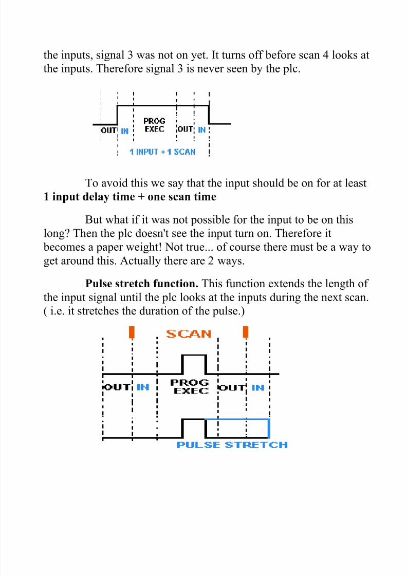
the inputs, signal 3 was not on yet. It turns off before scan 4 looks at
the inputs. Therefore signal 3 is never seen by the plc.
To avoid this we say that the input should be on for at least
1 input delay time + one scan time
But what if it was not possible for the input to be on this
long? Then the plc doesn't see the input turn on. Therefore it
becomes a paper weight! Not true... of course there must be a way to
get around this. Actually there are 2 ways.
Pulse stretch function. This function extends the length of
the input signal until the plc looks at the inputs during the next scan.( i.e. it stretches the duration of the pulse.)

7/28/2019 3.1) Responce Time
http://slidepdf.com/reader/full/31-responce-time 4/4
Interrupt function. This function interrupts the scan to
process a special routine that you have written. i.e. As soon as the
input turns on, regardless of where the scan currently is, the plc
immediately stops what its doing and executes an interrupt routine.(A routine can be thought of as a mini program outside of the main
program.) After its done executing the interrupt routine, it goes back
to the point it left off at and continues on with the normal scan
process.
Now let's consider the longest time for an output toactually turn on. Let's assume that when a switch turns on we
need to turn on a load connected to the plc output.The diagram below shows the longest delay (worst casebecause the input is not seen until scan 2) for the output toturn on after the input has turned on.The maximum delay is thus 2 scan cycles - 1 input delaytime.