306840n air-driven agitators - graco.com · 306840 3 warning fire and explosion hazard improper...
TRANSCRIPT

Instructions – Parts List
GRACO INC. P.O. BOX 1441 MINNEAPOLIS, MN 55440–1441Copyright 1992, Graco Inc. is registered to I.S. EN ISO 9001
Air–Driven Agitators 100 psi (0.7MPa, 7 bar) Maximum Working Pressure
306840N
Important Safety InformationRead all warnings and instructions in this manual.Save these instructions.
See page 2 for Table of Contents.
0359 II 1/2 G T6
Model 222698, Series AStainless Steel Agitator For 30-gallon mix tanks and 55-gallon drums,3/4 HP motor
Model 206758, Series ACarbon Steel Agitator For 30-gallon mix tanksand 55-gallon drums,3/4 HP motor
Model 206760, Series ACarbon Steel Agitator For 60-gallon mix tanks,1 1/2 HP motor
Model 207953, Series ACarbon Steel Agitator For 15-gallon mix tanks,3/4 HP motor
5457A
5455B
5456B
5458B
ITS03ATEX11226
2 306840
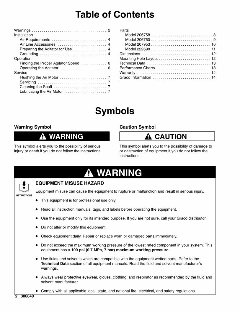
Table of ContentsWarnings 2. . . . . . . . . . . . . . . . . . . . . . . . . . . . . . . . . . . . . . Installation
Air Requirements 4. . . . . . . . . . . . . . . . . . . . . . . . . . . . Air Line Accessories 4. . . . . . . . . . . . . . . . . . . . . . . . . Preparing the Agitator for Use 4. . . . . . . . . . . . . . . . . Grounding 4. . . . . . . . . . . . . . . . . . . . . . . . . . . . . . . . . .
OperationFinding the Proper Agitator Speed 6. . . . . . . . . . . . . Operating the Agitator 6. . . . . . . . . . . . . . . . . . . . . . . .
ServiceFlushing the Air Motor 7. . . . . . . . . . . . . . . . . . . . . . . . Servicing 7. . . . . . . . . . . . . . . . . . . . . . . . . . . . . . . . . . . Cleaning the Shaft 7. . . . . . . . . . . . . . . . . . . . . . . . . . . Lubricating the Air Motor 7. . . . . . . . . . . . . . . . . . . . .
PartsModel 206758 8. . . . . . . . . . . . . . . . . . . . . . . . . . . . . . . Model 206760 9. . . . . . . . . . . . . . . . . . . . . . . . . . . . . . . Model 207953 10. . . . . . . . . . . . . . . . . . . . . . . . . . . . . . Model 222698 11. . . . . . . . . . . . . . . . . . . . . . . . . . . . . .
Dimensions 12. . . . . . . . . . . . . . . . . . . . . . . . . . . . . . . . . . . Mounting Hole Layout 12. . . . . . . . . . . . . . . . . . . . . . . . . . Technical Data 13. . . . . . . . . . . . . . . . . . . . . . . . . . . . . . . . Performance Charts 13. . . . . . . . . . . . . . . . . . . . . . . . . . . Warranty 14. . . . . . . . . . . . . . . . . . . . . . . . . . . . . . . . . . . . . Graco Information 14. . . . . . . . . . . . . . . . . . . . . . . . . . . . .
Symbols
Warning Symbol
WARNINGThis symbol alerts you to the possibility of seriousinjury or death if you do not follow the instructions.
Caution Symbol
CAUTIONThis symbol alerts you to the possibility of damage toor destruction of equipment if you do not follow theinstructions.
WARNING
INSTRUCTIONS
EQUIPMENT MISUSE HAZARD
Equipment misuse can cause the equipment to rupture or malfunction and result in serious injury.
� This equipment is for professional use only.
� Read all instruction manuals, tags, and labels before operating the equipment.
� Use the equipment only for its intended purpose. If you are not sure, call your Graco distributor.
� Do not alter or modify this equipment.
� Check equipment daily. Repair or replace worn or damaged parts immediately.
� Do not exceed the maximum working pressure of the lowest rated component in your system. Thisequipment has a 100 psi (0.7 MPa, 7 bar) maximum working pressure.
� Use fluids and solvents which are compatible with the equipment wetted parts. Refer to theTechnical Data section of all equipment manuals. Read the fluid and solvent manufacturer’swarnings.
� Always wear protective eyewear, gloves, clothing, and respirator as recommended by the fluid andsolvent manufacturer.
� Comply with all applicable local, state, and national fire, electrical, and safety regulations.

306840 3
WARNINGFIRE AND EXPLOSION HAZARD
Improper grounding, poor ventilation, open flames, or sparks can cause a hazardous condition andresult in a fire or explosion and serious injury.
� Ground the equipment and the object being sprayed. Refer to Grounding on page 5.
� If there is any static sparking or you feel an electric shock while using this equipment, stop spray-ing immediately. Do not use the equipment until you identify and correct the problem.
� Do not use 1,1,1–trichloroethane, methylene chloride, other halogenated hydrocarbon solvents, orfluids containing such solvents in aluminum pumps. Such use could result in a serious chemicalreaction, with the possibility of explosion.
� Do not use kerosene or other flammable solvents or combustible gases to flush the unit.
� Provide fresh air ventilation to avoid the buildup of flammable fumes from solvents or the fluidbeing sprayed.
� Keep the spray area free of debris, including solvent, rags, and gasoline.
� Before operating this equipment, electrically disconnect all equipment in the spray area.
� Before operating this equipment, extinguish all open flames or pilot lights in the spray area.
� Do not smoke in the spray area.
� Do not turn on or off any light switch in the spray area while spraying or while there are any fumesin the air.
� Do not operate a gasoline engine in the spray area.
� Keep a fire extinguisher in the work area.
MOVING PARTS HAZARD
Moving parts, such as the rotating blades of the agitator, can pinch or amputate your fingers or otherbody parts and can cause splashing in the eyes or on the skin.
� Keep clear of all moving parts when starting or operating the agitator.
� Always shut off the agitator and disconnect the air line before adjusting the angle of the agitator,removing the agitator from the drum, or checking or repairing any part of the agitator.
HAZARDOUS VAPORS
Hazardous fluids or toxic fumes can cause serious injury or death if splashed in the eyes or on theskin, swallowed, or inhaled. When flushing the air motor, keep your face away from the exhaust port.

4 306840
Installation
WARNINGFIRE AND EXPLOSION HAZARDAlways maintain a minimum of 1 in. clearancebetween rotating agitator parts and containerto prevent sparks from contact.
air line lubricatoragitator motor
air line filter
air regulatorand gauge
mix tank(reference only)
Typical Installation
NOTE: Reference numbers in parentheses in the textrefer to callouts in the figures and in the Parts draw-ings on pages 8 to 11.
Air RequirementsFor continuous use, the 3/4 HP (550 W) agitator airmotor typically requires 3 to 4 cfm (0.08 to 0.12m�/min). The 1 1/2 HP (1100 W) motor typically re-quires 6 to 8 cfm (0.17 to 0.23 m�/min).
Air Line AccessoriesAttach a quick-disconnect air line fitting (24) andcoupler (23), or attach a ball valve for main air shut-offto the air line. To order a 1/8 in. npt(m) air line fitting,order Part No. 169969. To order a coupler, order PartNo. 208536.
Install an air line filter to remove harmful dirt andmoisture from the air supply. To order a 3/8 in. npt(20-micron element, 5 oz. bowl, without gauge) air linefilter, order Part No. 106148.
CAUTIONNot lubricating the air motor will cause air motor failure.
Downstream from the filter, install an air line lubricatorfor automatic air motor lubrication. Set the lubricatorfeed rate at 1 drop of oil per minute for high speed orcontinuous duty usage. Do not overfeed oil or exhaustair may become contaminated. To manually lubricatethe air motor, see Lubricating the Air Motor on page7. To order a 3/8 in. npt air line lubricator, order PartNo. 214847.
Preparing the Agitator for Use
NOTE: The mounting gasket is not included with theagitator. To order, see the Mounting Hole Layout onpage 12 for the gasket part number.
1. Install the agitator on the cover of the fluid supplytank with the gasket in place.
2. Position the agitator so the air line can be attachedeasily and will not obstruct other tank openings,lines, etc. Then bolt it in place.
NOTE: Refer to the Dimensional Drawing andMounting Hole Layout on page 12. See Fig. 1 for airhose connections.
Fig. 1
Model 207953Connect a 1/8 in. npt(m) air hose from theair supply to the air control valve (1) on theair motor.
Models 206758 and 222698Connect the fixed end of the suppliedair hose (18) to the air control valve (1)and the swivel end to the air supply.
Model 206760Connect a 0.25 in. (6.4 mm) minimumID air hose to the 1/4 in. npt(f) quickcoupler (23).
1/4 in.npt(m)air inlet
1
231/4 in. npt(f) airinlet
11/8 in. npt(f)air inlet
TI0324A TI)325A TI0326A

306840 5
InstallationGroundingProper grounding is an essential part of maintaining asafe system.
To reduce the risk of static sparking, the mounting cov-er and all electrically conductive objects or devices inthe spray area must be properly grounded. Checkyour local electrical code for detailed groundinginstructions for your area and type of equipment.
To ground the agitator, connect one end of theground wire (A) to the ground connector (B) on the rimof the drum cover. See Fig. 2. Connect the other endof the ground wire to a true earth ground.
For a ground wire and clamp, order Part No. 237569.
AFig. 2
B
6 306840
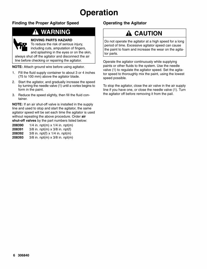
OperationFinding the Proper Agitator Speed
WARNINGMOVING PARTS HAZARDTo reduce the risk of serious injury,including cuts, amputation of fingers,and splashing in the eyes or on the skin,
always shut off the agitator and disconnect the airline before checking or repairing the agitator.
NOTE: Attach ground wire before using agitator.
1. Fill the fluid supply container to about 3 or 4 inches(75 to 100 mm) above the agitator blade.
2. Start the agitator, and gradually increase the speedby turning the needle valve (1) until a vortex begins toform in the paint.
3. Reduce the speed slightly, then fill the fluid con-tainer.
NOTE: If an air shut-off valve is installed in the supplyline and used to stop and start the agitator, the sameagitator speed will be set each time the agitator is usedwithout repeating the above procedure. Order airshut-off valves by the part numbers listed below:208390 1/4 in. npt(m) x 1/4 in. npt(m)208391 3/8 in. npt(m) x 3/8 in. npt(f)208392 3/8 in. npt(f) x 1/4 in. npt(m)208393 3/8 in. npt(m) x 3/8 in. npt(m)
Operating the Agitator
CAUTIONDo not operate the agitator at a high speed for a longperiod of time. Excessive agitator speed can causethe paint to foam and increase the wear on the agita-tor parts.
Operate the agitator continuously while supplyingpaints or other fluids to the system. Use the needlevalve (1) to regulate the agitator speed. Set the agita-tor speed to thoroughly mix the paint, using the lowestspeed possible.
To stop the agitator, close the air valve in the air supplyline if you have one, or close the needle valve (1). Turnthe agitator off before removing it from the pail.

306840 7
ServiceFlushing the Air Motor
WARNINGFIRE AND EXPLOSION HAZARDDo not use kerosene or other flam-mable solvents to flush the air motor.Flushing with flammable solvents could
cause fire or explosion and result in serious injuryor property damage.
WARNINGHAZARDOUS VAPORSHazardous fluids or toxic fumes cancause serious injury or death if splashedin the eyes or on the skin, swallowed, or
inhaled. When flushing the air motor:
� Keep your face away from the exhaust port.
� Wear the appropriate protective clothing,gloves, eyewear, and respirator.
If the motor is sluggish or inefficient, flush it with non-flammable solvent in a well ventilated area.
The recommended solvent for air motors and lubri-cated pumps is Gast� Flushing Solvent (Part No.AH255 or AH255A) or Inhibisol� Safety Solvent.
1. Disconnect the air line and muffler.
2. Add several teaspoons of solvent or spray the sol-vent directly into the motor.
3. Rotate the shaft by hand in both directions for afew minutes.
4. Reconnect the air line, and slowly increase the airpressure until there is no trace of solvent in theexhaust air.
5. Re-lubricate the motor with a squirt of light-weightoil in the chamber.
Gast� is a registered trademark of Gast Manufacturing.
Inhibisol� is a registered trademark of Penetone Corp.
Servicing
� If the unit requires more than installation of a ser-vice kit, it is usually quickest and easiest to sendthe unit to the Graco distributor for repair or re-placement.
� If the vanes need replacing, or if foreign material ispresent in the motor chamber, an experienced me-chanic may remove the end plate opposite the driveshaft end. Do not pry with a screwdriver. It will dentthe surface of the plate and body, causing leaks.Use a puller tool, which will remove the end platewhile maintaining the position of the shaft.
� New vanes should have the edges with cut corners(or the notched edges, if the vanes are reversible)pointing toward the bottom of the vane slot.
Cleaning the Shaft
Each week, clean any dried fluid from around thebearing (21) and guide (6) area of the shaft (20).
Lubricating the Air Motor
CAUTIONNot lubricating the air motor will cause air motor failure.
If an air line lubricator is not installed, the air motormust be manually lubricated every 8 hours. Lubricatethe agitator air motor by placing 10–20 drops of SAE#10 light oil in the motor’s air inlet. Run the agitator forabout 30 seconds.
8 306840
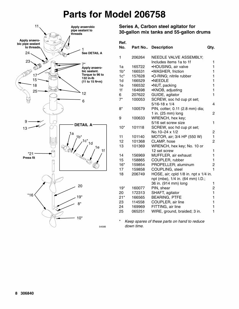
Parts for Model 206758
DETAIL A
5459B
25
15
Apply anaero-bic sealant.Torque to 96 to132 in-lb(11 to 15 N�m)
*21
9
*16
Apply anaerobicpipe sealant tothreads
Press fit
7*
11
17
13
1See DETAIL A
1a1b*
1c*1d
1e1f
12
6
20
19*
8*
10*
18
Apply anaero-bic pipe sealant
to threads
24
23
Series A, Carbon steel agitator for30-gallon mix tanks and 55-gallon drums
Ref. No. Part No.. Description Qty.
1 206264 NEEDLE VALVE ASSEMBLY; Includes items 1a to 1f 1
1a 165722 �HOUSING, air valve 11b* 166531 �WASHER, friction 11c* 157628 �O-RING; nitrile rubber 11d 166529 �NEEDLE 11e 166532 �NUT, packing 11f 164698 �KNOB, adjusting 16 207622 GUIDE, agitator 17* 100053 SCREW, soc hd cup pt set;
5/16-18 x 1/4 48* 100579 PIN, cotter; 0.11 (2.8 mm) dia;
1 in. (25 mm) long 29 100633 WRENCH, hex key;
5/16 set screw size 110* 101118 SCREW, soc hd cup pt set;
No.10–24 x 1/2 211 101140 MOTOR, air; 3/4 HP (550 W) 112 101368 CLAMP, hose 213 101369 WRENCH, hex key; No. 10 or
12 set screw 114 156969 MUFFLER, air exhaust 115 158865 COUPLER, rubber 116* 159854 PROPELLER; aluminum 217 159858 COUPLING, steel 118 206749 HOSE, air; cpld 1/8 in. npt x 1/4 in.
npt (mbe), 1/4 in. (64 mm) I.D.; 36 in. (914 mm) long 1
19* 160077 PIN, shear 220 172313 SHAFT, agitator 121* 166565 BEARING, PTFE 123 114558 COUPLER, air line 124 169969 FITTING, air line 125 065251 WIRE, ground, braided; 3 in. 1
* Keep spares of these parts on hand to reduce down time.

306840 9
Parts for Model 206760
DETAIL A
25
15
Apply anaero-bic sealant.Torque to 96 to132 in-lb(11 to 15 N�m)
*21
9
*16
Apply anaerobicpipe sealant tothreads
Press fit
7*
11
17
13
1See DETAIL A
1a1b*
1c*1d
1e1f
12
6
20
19*
8*
10*
Apply anaero-bic pipe sealant
to threads
24
23
5460B
Series A, Carbon steel agitator for60-gallon mix tanks
Ref. No. Part No. Description Qty.
1 206264 NEEDLE VALVE ASSEMBLY; Includes items 1a–1f 1
1a 165722 �HOUSING, air valve 11b* 166531 �WASHER, friction 11c* 157628 �O-RING; nitrile rubber 11d 166529 �NEEDLE 11e 166532 �NUT, packing 11f 164698 �KNOB, adjusting 16 206759 GUIDE, agitator 17* 100053 SCREW, soc hd cup pt set;
5/16-18 x 1/4 48* 100579 PIN, cotter; 0.11 (2.8 mm) dia;
1 in. (25 mm) long 29 100633 WRENCH, hex key;
5/16 set screw size 110* 101118 SCREW, soc hd cup pt set;
No.10–24 x 1/2 211 101388 MOTOR, air; 1 1/2 HP (1100 W) 112 101368 CLAMP, hose 213 101369 WRENCH, hex key; No. 10 or
12 set screw 115 158865 COUPLER, rubber 116* 159854 PROPELLER; aluminum 217 159858 COUPLING, steel 119* 160077 PIN, shear 220 172311 SHAFT, agitator 121* 166565 BEARING, PTFE 123 114558 COUPLER, air line 124 169969 FITTING, air line 125 065251 WIRE, ground, braided; 3 in. 1
* Keep spares of these parts on hand to reduce down time.

10 306840
Parts for Model 207953
25
15
Apply anaerobicsealant. Torqueto 96 to 132 in-lb(11 to 15 N�m)
*21
9
*16
Apply anaerobicpipe sealant tothreads
Press fit
DETAIL A
7*
11
17
13
1See DETAIL A
1a1b*
1c*1d
1e1f
12
6
20
19*
8*
10*
5461A
Series A, Carbon steel agitator for15-gallon mix tanks
Ref.No. Part No. Description Qty.
1 206264 NEEDLE VALVE ASSEMBLY; Includes items 1a to 1f 1
1a 165722 �HOUSING, air valve 11b* 166531 �WASHER, friction 11c* 157628 �O-RING; nitrile rubber 11d 166529 �NEEDLE 11e 166532 �NUT, packing 11f 164698 �KNOB, adjusting 16 207431 GUIDE, agitator 17* 100053 SCREW, soc hd cup pt set;
5/16-18 x 1/4 48* 100579 PIN, cotter; 0.11 (2.8 mm) dia;
1 in. (25 mm) long 29 100633 WRENCH, hex key;
5/16 set screw size 110* 101118 SCREW, soc hd cup pt set;
No.10–24 x 1/2 211 101140 MOTOR, air; 3/4 HP (550 W) 112 101368 CLAMP, hose 213 101369 WRENCH, hex key; No. 10 or
12 set screw 114 156969 MUFFLER, air exhaust 115 158865 COUPLER, rubber 116* 159854 PROPELLER; aluminum 217 159858 COUPLING, steel 119* 160077 PIN, shear 220 172353 SHAFT, agitator 121* 166565 BEARING, PTFE 125 065251 WIRE, ground, braided; 3 in. 1
* Keep spares of these parts on hand to reduce down time.

306840 11
Parts for Model 222698
5462B
25
15
Apply anaero-bic sealant.Torque to 96 to132 in-lb(11 to 15 N�m)
*21
9
*16
Apply anaerobicpipe sealant tothreads
Press fit
DETAIL A
7*
11
17
13
1See DETAIL A
1a1b*
1c*1d
1e1f
12
6
20
19*
8*
10*
18
Apply anaero-bic pipe sealant
to threads
24
23
Series A, Stainless steel agitator for30-gallon mix tanks and 55-gallon drums
Ref.No. Part No. Description Qty.
1 206264 NEEDLE VALVE ASSEMBLY; Includes items 1a to 1f 1
1a 165722 �HOUSING, air valve 11b* 166531 �WASHER, friction 11c* 157628 �O-RING; nitrile rubber 11d 166529 �NEEDLE 11e 166532 �NUT, packing 11f 164698 �KNOB, adjusting 16 222696 GUIDE, agitator 17* 100053 SCREW, soc hd cup pt set;
5/16-18 x 1/4 38* 100579 PIN, cotter; 0.11 (2.8 mm) dia;
1 in. (25 mm) long 19 100633 WRENCH, hex key;
5/16 set screw size 110* 110248 SCREW, soc hd cup pt set;
No.10–24 x 1/4 111 101140 MOTOR, air; 3/4 HP (550 W) 112 101368 CLAMP, hose 213 101369 WRENCH, hex key; No. 10 or
12 set screw 114 156969 MUFFLER, air exhaust 115 158865 COUPLER, rubber 116* 185398 PROPELLER; stainless steel 117 159858 COUPLING, steel 118 206749 HOSE, air; cpld 1/8 in. npt x 1/4 in.
npt (mbe), 1/4 in. (64 mm) I.D.; 36 in. (914 mm) long 1
19* 185401 PIN, shear 220 185389 SHAFT, agitator 121* 115166 BEARING 123 114558 COUPLER, air line 124 169969 FITTING, air line 125 065251 WIRE, ground, braided; 3 in. 1
* Keep spares of these parts on hand to reduce down time.
12 306840
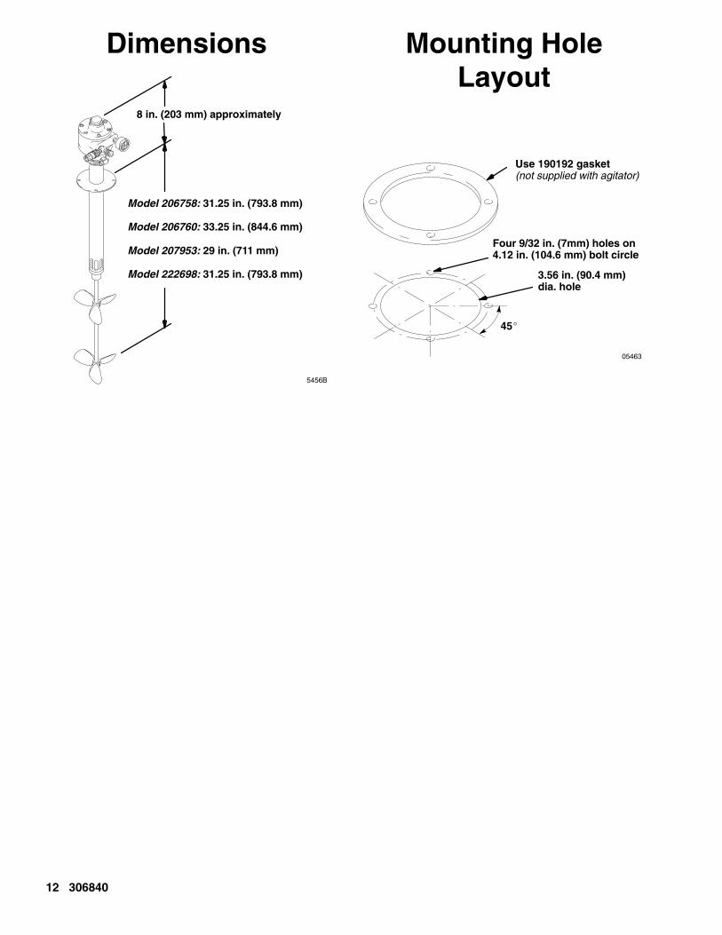
Dimensions
8 in. (203 mm) approximately
Model 206758: 31.25 in. (793.8 mm)
Model 206760: 33.25 in. (844.6 mm)
Model 207953: 29 in. (711 mm)
Model 222698: 31.25 in. (793.8 mm)
5456B
Mounting HoleLayout
05463
Use 190192 gasket(not supplied with agitator)
45�
Four 9/32 in. (7mm) holes on4.12 in. (104.6 mm) bolt circle
3.56 in. (90.4 mm)dia. hole

306840 13
Technical DataMaximum working pressure 100 psi (7 bar). . . . . . . . . . Motor power rating:
Models 206758, 207953, and 222698 3/4 HP (550 W). . . . . . . . . . . . . . . . . . . . Model 206760 1 1/2 HP (1100 W). . . . . . . . . . . . . . . .
Wetted parts:Models 206758, 207953, and 206760 aluminum, PTFE, carbon steel. . . . . . . Model 222698 stainless steel,. . . . . . . . . . . . . . . . . . .
polyether ether ketoneAir consumption See Performance Charts at right. . *Sound data:
Sound level at 800 RPM, 100 psi, normal loadPressure level 66.8 dB(A). . . . . . . . . . . . . . . . . . . . Power level 79.9 dB(A). . . . . . . . . . . . . . . . . . . . . .
Sound level at maximum RPM, 100 psi, no loadPressure level 86.2 dB(A). . . . . . . . . . . . . . . . . . . . Power level 99.4 dB(A). . . . . . . . . . . . . . . . . . . . . .
Weight 9.9 lb (4.5 kg). . . . . . . . . . . . . . . . . . . . . . . . . . . . .
* Tested to CAGI-PNEUROP–1969
Performance Charts
500 1000 1500 2000 2500 300000
5
10
15
20
25
30
��
���
��
��
���
��
��
�
��
��
�
����������������
3/4 HORSEPOWER MOTOR
500 1000 1500 2000 2500 3000
��
���
��
��
���
��
��
�
��
��
�
����������������
1 1/2 HORSEPOWER MOTOR
10
20
30
40
50
60
70
80
00
NOTE: Lines on the graphs show air inlet pressure.

14 306840
Graco Standard WarrantyGraco warrants all equipment manufactured by Graco and bearing its name to be free from defects in material and workmanship on thedate of sale to the original purchaser for use. With the exception of any special, extended, or limited warranty published by Graco,Graco will, for a period of twelve months from the date of sale, repair or replace any part of the equipment determined by Graco to bedefective. This warranty applies only when the equipment is installed, operated and maintained in accordance with Graco’s writtenrecommendations.
This warranty does not cover, and Graco shall not be liable for general wear and tear, or any malfunction, damage or wear caused byfaulty installation, misapplication, abrasion, corrosion, inadequate or improper maintenance, negligence, accident, tampering, or sub-stitution of non–Graco component parts. Nor shall Graco be liable for malfunction, damage or wear caused by the incompatibility ofGraco equipment with structures, accessories, equipment or materials not supplied by Graco, or the improper design, manufacture,installation, operation or maintenance of structures, accessories, equipment or materials not supplied by Graco.
This warranty is conditioned upon the prepaid return of the equipment claimed to be defective to an authorized Graco distributor forverification of the claimed defect. If the claimed defect is verified, Graco will repair or replace free of charge any defective parts. Theequipment will be returned to the original purchaser transportation prepaid. If inspection of the equipment does not disclose any defectin material or workmanship, repairs will be made at a reasonable charge, which charges may include the costs of parts, labor, andtransportation.
THIS WARRANTY IS EXCLUSIVE, AND IS IN LIEU OF ANY OTHER WARRANTIES, EXPRESS OR IMPLIED, INCLUDING BUTNOT LIMITED TO WARRANTY OF MERCHANTABILITY OR WARRANTY OF FITNESS FOR A PARTICULAR PURPOSE.
Graco’s sole obligation and buyer’s sole remedy for any breach of warranty shall be as set forth above. The buyer agrees that no otherremedy (including, but not limited to, incidental or consequential damages for lost profits, lost sales, injury to person or property, or anyother incidental or consequential loss) shall be available. Any action for breach of warranty must be brought within two (2) years of thedate of sale.
Graco makes no warranty, and disclaims all implied warranties of merchantability and fitness for a particular purpose in connectionwith accessories, equipment, materials or components sold but not manufactured by Graco. These items sold, but not manufacturedby Graco (such as electric motors, switches, hose, etc.), are subject to the warranty, if any, of their manufacturer. Graco will providepurchaser with reasonable assistance in making any claim for breach of these warranties.
In no event will Graco be liable for indirect, incidental, special or consequential damages resulting from Graco supplying equipmenthereunder, or the furnishing, performance, or use of any products or other goods sold hereto, whether due to a breach of contract,breach of warranty, the negligence of Graco, or otherwise.
FOR GRACO CANADA CUSTOMERSThe parties acknowledge that they have required that the present document, as well as all documents, notices and legal proceedingsentered into, given or instituted pursuant hereto or relating directly or indirectly hereto, be drawn up in English. Les parties reconnais-sent avoir convenu que la rédaction du présente document sera en Anglais, ainsi que tous documents, avis et procédures judiciairesexécutés, donnés ou intentés à la suite de ou en rapport, directement ou indirectement, avec les procedures concernées.
Graco InformationTO PLACE AN ORDER, contact your Graco distributor, or call this number to identify the distributor closest to you:
1–800–328–0211 Toll Free612–623–6921
612–378–3505 Fax
All written and visual data contained in this document reflects the latest product information available at the time of publication.Graco reserves the right to make changes at any time without notice.
MM 306840
Graco Headquarters: MinneapolisInternational Offices: Belgium, China, Japan, Korea
GRACO INC. P.O. BOX 1441 MINNEAPOLIS, MN 55440–1441www.graco.com
PRINTED IN USA 306840 05/1964, Revised 11/2005