3030 s susan street, santa ana, ca 92704 cobra ... street, santa ana, ca 92704 cobra series...
TRANSCRIPT
August, 2014 IMPCO Technologies Inc. PPI-36 REV. F 3030 South Susan St. Page 1 of 12 Santa Ana, CA 92704
www.impcotechnologies.com
3030 S Susan Street, Santa Ana, CA 92704
COBRA SERIES CONVERTER
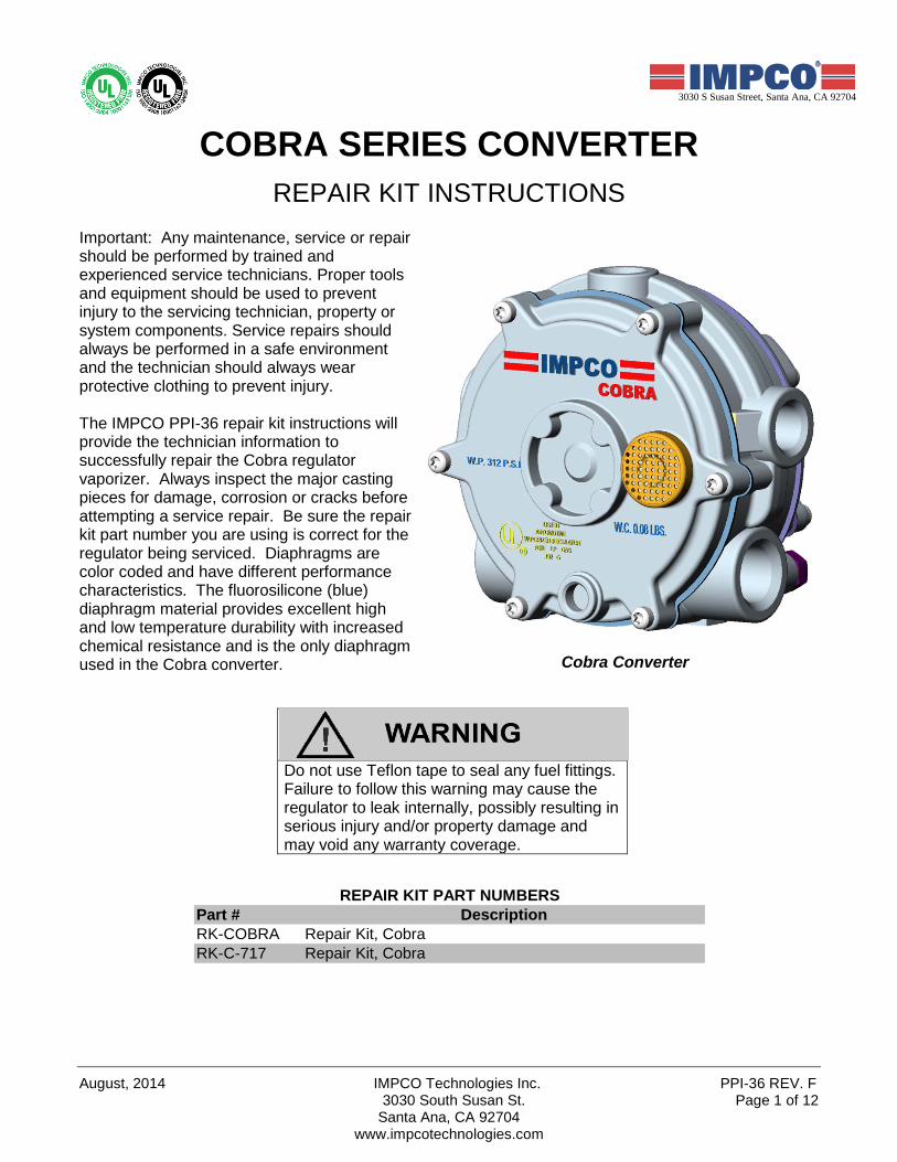
REPAIR KIT INSTRUCTIONS Important: Any maintenance, service or repair should be performed by trained and experienced service technicians. Proper tools and equipment should be used to prevent injury to the servicing technician, property or system components. Service repairs should always be performed in a safe environment and the technician should always wear protective clothing to prevent injury. The IMPCO PPI-36 repair kit instructions will provide the technician information to successfully repair the Cobra regulator vaporizer. Always inspect the major casting pieces for damage, corrosion or cracks before attempting a service repair. Be sure the repair kit part number you are using is correct for the regulator being serviced. Diaphragms are color coded and have different performance characteristics. The fluorosilicone (blue) diaphragm material provides excellent high and low temperature durability with increased chemical resistance and is the only diaphragm used in the Cobra converter.
Cobra Converter
Do not use Teflon tape to seal any fuel fittings. Failure to follow this warning may cause the regulator to leak internally, possibly resulting in serious injury and/or property damage and may void any warranty coverage.
Part # DescriptionRK-COBRA Repair Kit, CobraRK-C-717 Repair Kit, Cobra
REPAIR KIT PART NUMBERS
PPI-36 REV. F IMPCO Technologies Inc. August, 2014 Page 2 of 12 3030 South Susan St.
Santa Ana, CA 92704 www.impcotechnologies.com
Ph: +1 714 656 1200 Fax: +1 714 656 14003030 S Susan Street, Santa Ana, CA 92704
COBRA SERIES CONVERTER
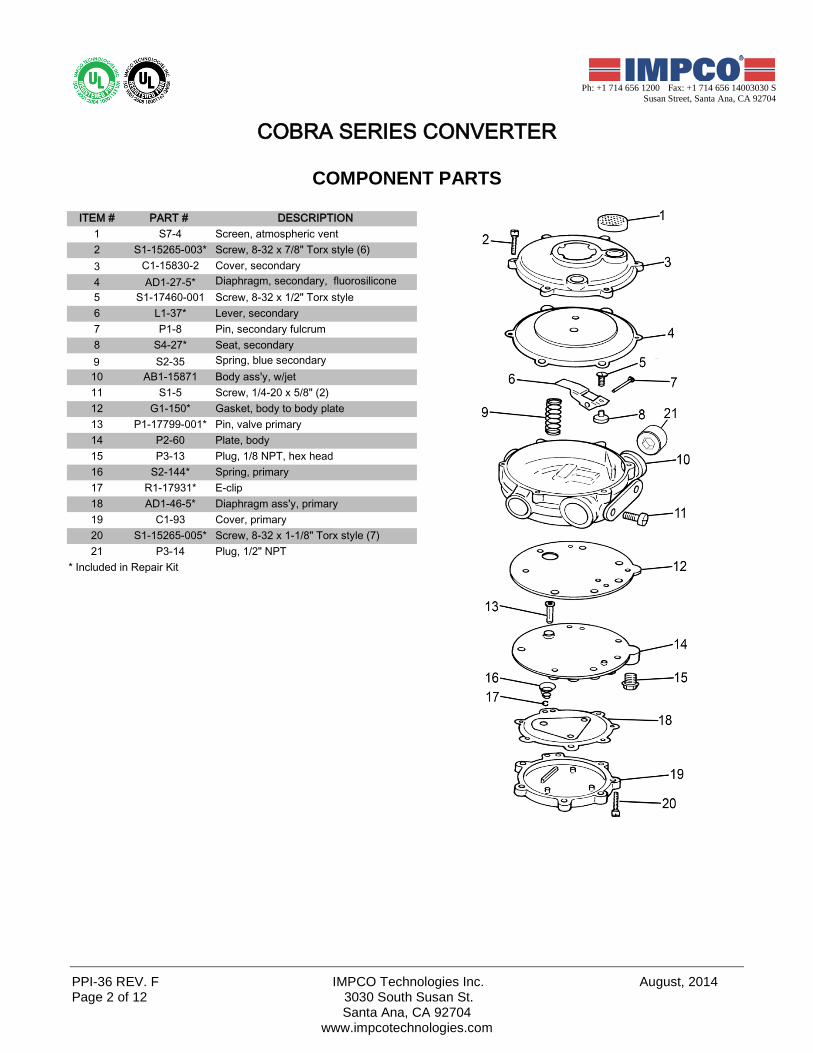
COMPONENT PARTS
ITEM # PART # DESCRIPTION1 S7-4 Screen, atmospheric vent2 S1-15265-003* Screw, 8-32 x 7/8" Torx style (6)3 C1-15830-2 Cover, secondary4 AD1-27-5* Diaphragm, secondary, fluorosilicone5 S1-17460-001 Screw, 8-32 x 1/2" Torx style6 L1-37* Lever, secondary7 P1-8 Pin, secondary fulcrum8 S4-27* Seat, secondary9 S2-35 Spring, blue secondary10 AB1-15871 Body ass'y, w/jet11 S1-5 Screw, 1/4-20 x 5/8" (2)12 G1-150* Gasket, body to body plate13 P1-17799-001* Pin, valve primary14 P2-60 Plate, body15 P3-13 Plug, 1/8 NPT, hex head16 S2-144* Spring, primary17 R1-17931* E-clip18 AD1-46-5* Diaphragm ass'y, primary19 C1-93 Cover, primary20 S1-15265-005* Screw, 8-32 x 1-1/8" Torx style (7)21 P3-14 Plug, 1/2" NPT
* Included in Repair Kit
August, 2014 IMPCO Technologies Inc. PPI-36 REV. F 3030 South Susan St. Page 3 of 12 Santa Ana, CA 92704
www.impcotechnologies.com
3030 S Susan Street, Santa Ana, CA 92704
REBUILD INSTRUCTIONS
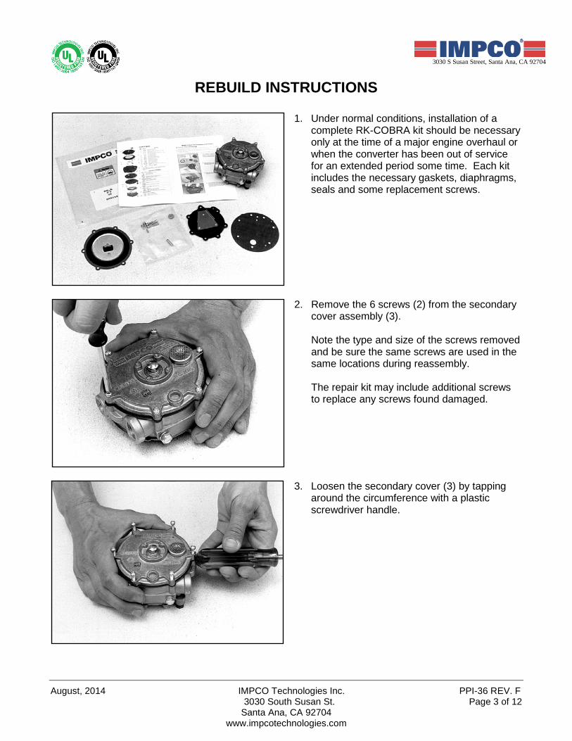
1. Under normal conditions, installation of a complete RK-COBRA kit should be necessary only at the time of a major engine overhaul or when the converter has been out of service for an extended period some time. Each kit includes the necessary gaskets, diaphragms, seals and some replacement screws.
2. Remove the 6 screws (2) from the secondary cover assembly (3).
Note the type and size of the screws removed and be sure the same screws are used in the same locations during reassembly. The repair kit may include additional screws to replace any screws found damaged.
3. Loosen the secondary cover (3) by tapping around the circumference with a plastic screwdriver handle.
PPI-36 REV. F IMPCO Technologies Inc. August, 2014 Page 4 of 12 3030 South Susan St.
Santa Ana, CA 92704 www.impcotechnologies.com
Ph: +1 714 656 1200 Fax: +1 714 656 14003030 S Susan Street, Santa Ana, CA 92704
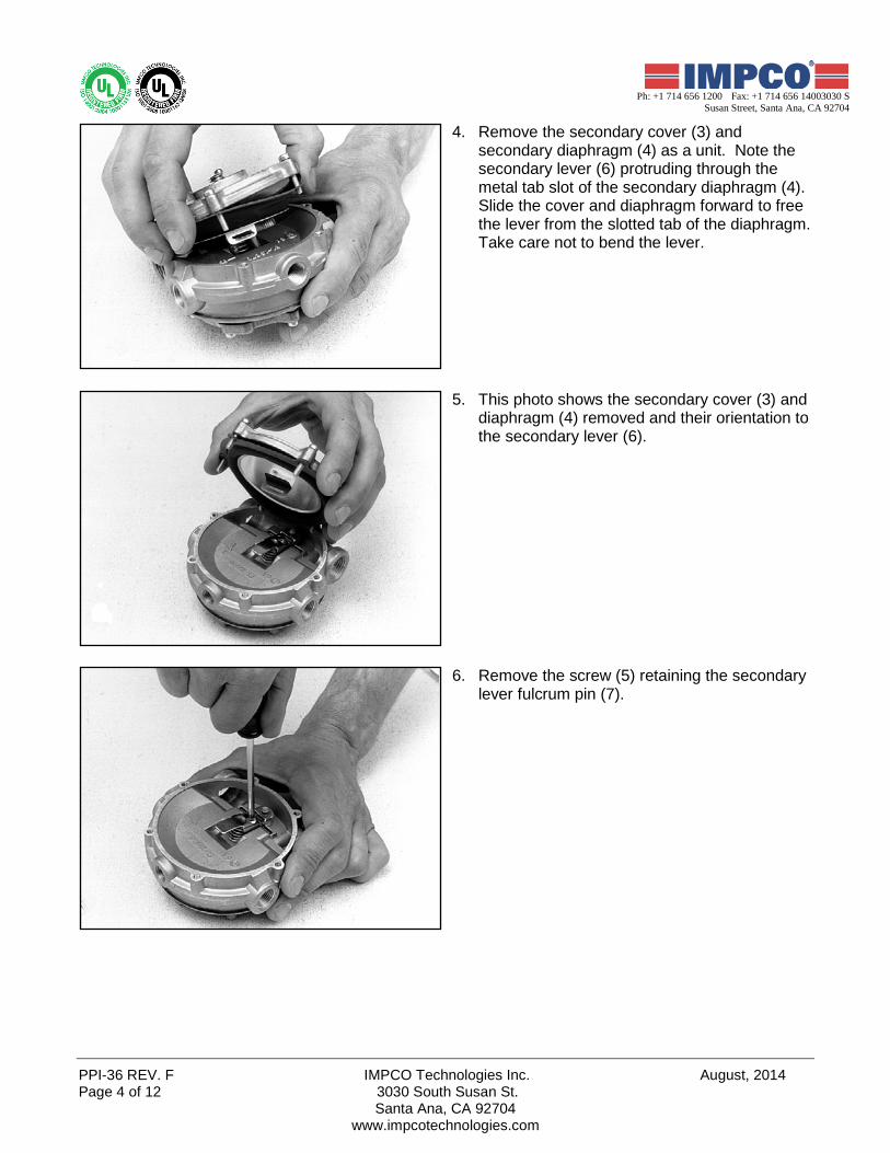
4. Remove the secondary cover (3) and secondary diaphragm (4) as a unit. Note the secondary lever (6) protruding through the metal tab slot of the secondary diaphragm (4). Slide the cover and diaphragm forward to free the lever from the slotted tab of the diaphragm. Take care not to bend the lever.
5. This photo shows the secondary cover (3) and diaphragm (4) removed and their orientation to the secondary lever (6).
6. Remove the screw (5) retaining the secondary lever fulcrum pin (7).
August, 2014 IMPCO Technologies Inc. PPI-36 REV. F 3030 South Susan St. Page 5 of 12 Santa Ana, CA 92704
www.impcotechnologies.com
3030 S Susan Street, Santa Ana, CA 92704
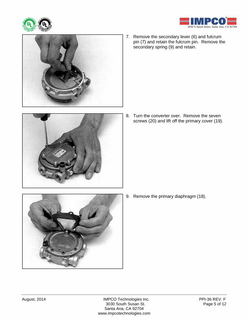
7. Remove the secondary lever (6) and fulcrum pin (7) and retain the fulcrum pin. Remove the secondary spring (9) and retain.
8. Turn the converter over. Remove the seven screws (20) and lift off the primary cover (19).
9. Remove the primary diaphragm (18).
PPI-36 REV. F IMPCO Technologies Inc. August, 2014 Page 6 of 12 3030 South Susan St.
Santa Ana, CA 92704 www.impcotechnologies.com
Ph: +1 714 656 1200 Fax: +1 714 656 14003030 S Susan Street, Santa Ana, CA 92704
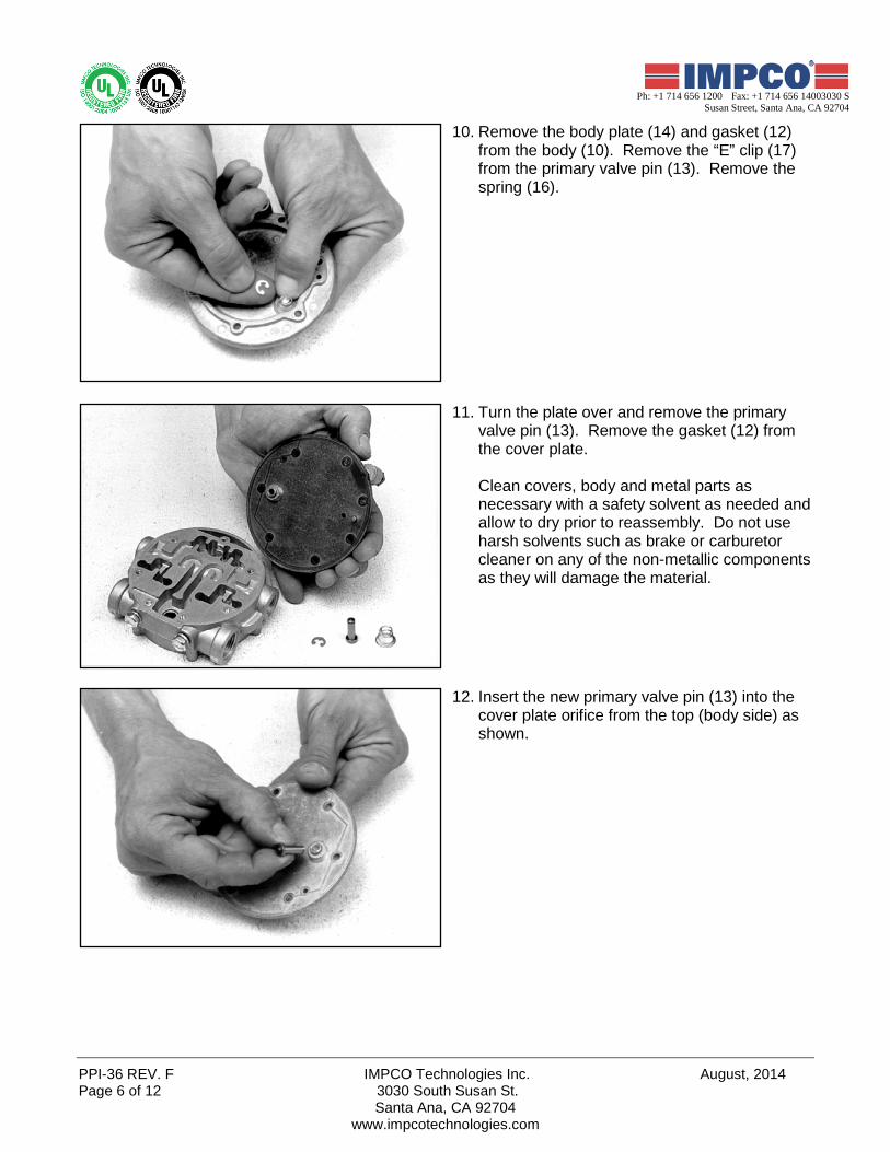
10. Remove the body plate (14) and gasket (12) from the body (10). Remove the “E” clip (17) from the primary valve pin (13). Remove the spring (16).
11. Turn the plate over and remove the primary valve pin (13). Remove the gasket (12) from the cover plate.
Clean covers, body and metal parts as necessary with a safety solvent as needed and allow to dry prior to reassembly. Do not use harsh solvents such as brake or carburetor cleaner on any of the non-metallic components as they will damage the material.
12. Insert the new primary valve pin (13) into the cover plate orifice from the top (body side) as shown.

August, 2014 IMPCO Technologies Inc. PPI-36 REV. F 3030 South Susan St. Page 7 of 12 Santa Ana, CA 92704
www.impcotechnologies.com
3030 S Susan Street, Santa Ana, CA 92704
13. Holding the valve pin (13) in place, turn the body plate (14) over. Place the valve pin spring (16) over the valve pin with the larger diameter end of the spring resting against the plate. Compress the spring and secure it in place by installing the “E” ring (17) retaining clip to the valve.
14. Install new gasket (12) making sure to align the small holes in the gasket to the matching holes in the plate (14).
15. Set new primary diaphragm (18) on the body (10). Screw hole spacing prevents improper orientation of the diaphragm.
PPI-36 REV. F IMPCO Technologies Inc. August, 2014 Page 8 of 12 3030 South Susan St.
Santa Ana, CA 92704 www.impcotechnologies.com
Ph: +1 714 656 1200 Fax: +1 714 656 14003030 S Susan Street, Santa Ana, CA 92704
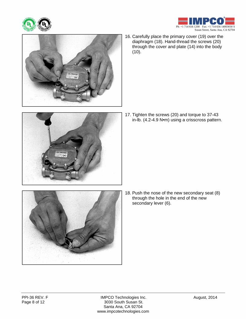
16. Carefully place the primary cover (19) over the diaphragm (18). Hand-thread the screws (20) through the cover and plate (14) into the body (10).
17. Tighten the screws (20) and torque to 37-43 in-lb. (4.2-4.9 N•m) using a crisscross pattern.
18. Push the nose of the new secondary seat (8) through the hole in the end of the new secondary lever (6).
August, 2014 IMPCO Technologies Inc. PPI-36 REV. F 3030 South Susan St. Page 9 of 12 Santa Ana, CA 92704
www.impcotechnologies.com
3030 S Susan Street, Santa Ana, CA 92704
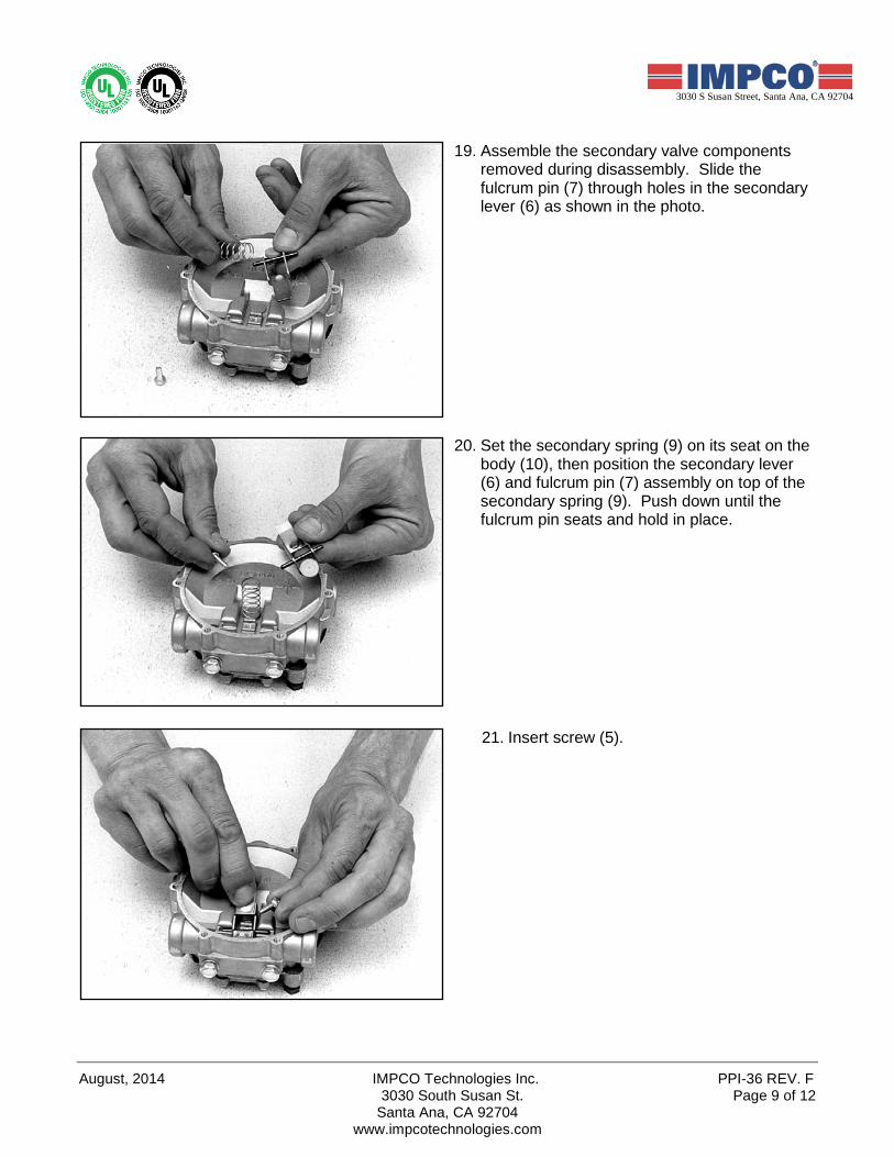
19. Assemble the secondary valve components removed during disassembly. Slide the fulcrum pin (7) through holes in the secondary lever (6) as shown in the photo.
20. Set the secondary spring (9) on its seat on the body (10), then position the secondary lever (6) and fulcrum pin (7) assembly on top of the secondary spring (9). Push down until the fulcrum pin seats and hold in place.
21. Insert screw (5).

PPI-36 REV. F IMPCO Technologies Inc. August, 2014 Page 10 of 12 3030 South Susan St.
Santa Ana, CA 92704 www.impcotechnologies.com
Ph: +1 714 656 1200 Fax: +1 714 656 14003030 S Susan Street, Santa Ana, CA 92704
22. Tighten screw to 29-35 in-lb. (3.3-4.0 N•m). Check the secondary lever height. Using a straight edge, the end of the secondary lever should 1/32" (0.794 mm) below the casting level.
NOTE: If the lever must be bent, remove from the body, bend, reinstall and check height. Bending the lever while installed may result in damage to the seat.
23. Align the secondary diaphragm (4) to the secondary lever (6) as shown. The end of the lever must protrude through the tab slot on the bottom of the new diaphragm after installation. The screw hole spacing prevents improper positioning of secondary diaphragm.
24. Add the secondary cover (3) and install the previously removed screws (2).
August, 2014 IMPCO Technologies Inc. PPI-36 REV. F 3030 South Susan St. Page 11 of 12
Santa Ana, CA 92704 www.impcotechnologies.com
3030 S Susan Street, Santa Ana, CA 92704
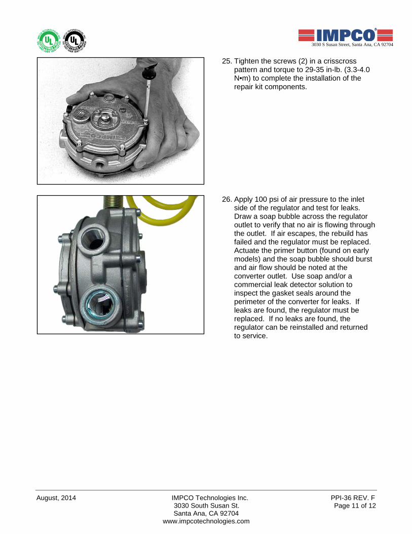
25. Tighten the screws (2) in a crisscross pattern and torque to 29-35 in-lb. (3.3-4.0 N•m) to complete the installation of the repair kit components.
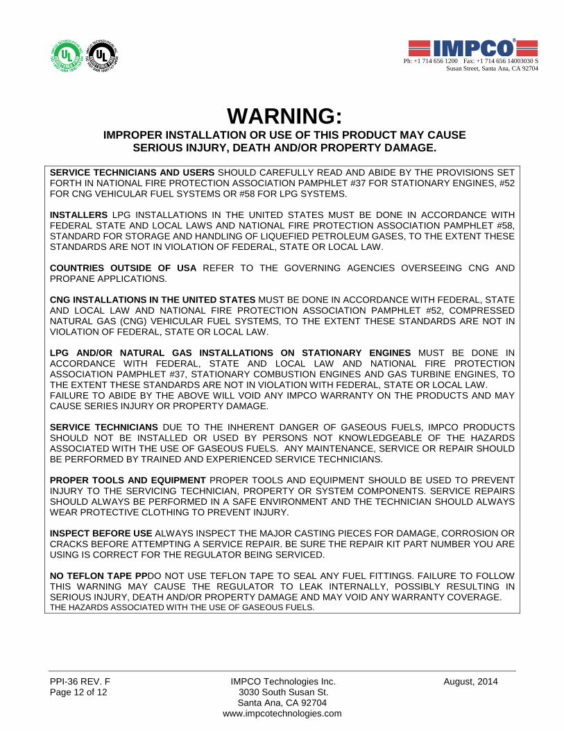
26. Apply 100 psi of air pressure to the inlet side of the regulator and test for leaks. Draw a soap bubble across the regulator outlet to verify that no air is flowing through the outlet. If air escapes, the rebuild has failed and the regulator must be replaced. Actuate the primer button (found on early models) and the soap bubble should burst and air flow should be noted at the converter outlet. Use soap and/or a commercial leak detector solution to inspect the gasket seals around the perimeter of the converter for leaks. If leaks are found, the regulator must be replaced. If no leaks are found, the regulator can be reinstalled and returned to service.
PPI-36 REV. F IMPCO Technologies Inc. August, 2014 Page 12 of 12 3030 South Susan St.
Santa Ana, CA 92704 www.impcotechnologies.com
Ph: +1 714 656 1200 Fax: +1 714 656 14003030 S Susan Street, Santa Ana, CA 92704
WARNING:
IMPROPER INSTALLATION OR USE OF THIS PRODUCT MAY CAUSE SERIOUS INJURY, DEATH AND/OR PROPERTY DAMAGE.
SERVICE TECHNICIANS AND USERS SHOULD CAREFULLY READ AND ABIDE BY THE PROVISIONS SET FORTH IN NATIONAL FIRE PROTECTION ASSOCIATION PAMPHLET #37 FOR STATIONARY ENGINES, #52 FOR CNG VEHICULAR FUEL SYSTEMS OR #58 FOR LPG SYSTEMS. INSTALLERS LPG INSTALLATIONS IN THE UNITED STATES MUST BE DONE IN ACCORDANCE WITH FEDERAL STATE AND LOCAL LAWS AND NATIONAL FIRE PROTECTION ASSOCIATION PAMPHLET #58, STANDARD FOR STORAGE AND HANDLING OF LIQUEFIED PETROLEUM GASES, TO THE EXTENT THESE STANDARDS ARE NOT IN VIOLATION OF FEDERAL, STATE OR LOCAL LAW. COUNTRIES OUTSIDE OF USA REFER TO THE GOVERNING AGENCIES OVERSEEING CNG AND PROPANE APPLICATIONS. CNG INSTALLATIONS IN THE UNITED STATES MUST BE DONE IN ACCORDANCE WITH FEDERAL, STATE AND LOCAL LAW AND NATIONAL FIRE PROTECTION ASSOCIATION PAMPHLET #52, COMPRESSED NATURAL GAS (CNG) VEHICULAR FUEL SYSTEMS, TO THE EXTENT THESE STANDARDS ARE NOT IN VIOLATION OF FEDERAL, STATE OR LOCAL LAW. LPG AND/OR NATURAL GAS INSTALLATIONS ON STATIONARY ENGINES MUST BE DONE IN ACCORDANCE WITH FEDERAL, STATE AND LOCAL LAW AND NATIONAL FIRE PROTECTION ASSOCIATION PAMPHLET #37, STATIONARY COMBUSTION ENGINES AND GAS TURBINE ENGINES, TO THE EXTENT THESE STANDARDS ARE NOT IN VIOLATION WITH FEDERAL, STATE OR LOCAL LAW. FAILURE TO ABIDE BY THE ABOVE WILL VOID ANY IMPCO WARRANTY ON THE PRODUCTS AND MAY CAUSE SERIES INJURY OR PROPERTY DAMAGE. SERVICE TECHNICIANS DUE TO THE INHERENT DANGER OF GASEOUS FUELS, IMPCO PRODUCTS SHOULD NOT BE INSTALLED OR USED BY PERSONS NOT KNOWLEDGEABLE OF THE HAZARDS ASSOCIATED WITH THE USE OF GASEOUS FUELS. ANY MAINTENANCE, SERVICE OR REPAIR SHOULD BE PERFORMED BY TRAINED AND EXPERIENCED SERVICE TECHNICIANS. PROPER TOOLS AND EQUIPMENT PROPER TOOLS AND EQUIPMENT SHOULD BE USED TO PREVENT INJURY TO THE SERVICING TECHNICIAN, PROPERTY OR SYSTEM COMPONENTS. SERVICE REPAIRS SHOULD ALWAYS BE PERFORMED IN A SAFE ENVIRONMENT AND THE TECHNICIAN SHOULD ALWAYS WEAR PROTECTIVE CLOTHING TO PREVENT INJURY. INSPECT BEFORE USE ALWAYS INSPECT THE MAJOR CASTING PIECES FOR DAMAGE, CORROSION OR CRACKS BEFORE ATTEMPTING A SERVICE REPAIR. BE SURE THE REPAIR KIT PART NUMBER YOU ARE USING IS CORRECT FOR THE REGULATOR BEING SERVICED. NO TEFLON TAPE PPDO NOT USE TEFLON TAPE TO SEAL ANY FUEL FITTINGS. FAILURE TO FOLLOW THIS WARNING MAY CAUSE THE REGULATOR TO LEAK INTERNALLY, POSSIBLY RESULTING IN SERIOUS INJURY, DEATH AND/OR PROPERTY DAMAGE AND MAY VOID ANY WARRANTY COVERAGE. THE HAZARDS ASSOCIATED WITH THE USE OF GASEOUS FUELS.