301-99 specifications for structural concrete -...
TRANSCRIPT
Reported by ACI Committee 301
James A. LeeChairman
W. Calvin McCallSecretary
Jon B. Ardahl Mario R. Diaz Gilbert J. Haddad Joseph A. McElroy
Domingo J. Carreira Robert M. Eshbach Jerry A. Holland Timothy L. Moore
Oleh B. Ciuk W. Bryant Frye Roy H. Keck Jerry Parnes
Steven R. Close Richard D. Gaynor Oswin Keifer, Jr.* Aimee Pergalsky
D. Gene Daniel Clifford Gordon Ross S. Martin James M. Shilstone, Sr.
Marwan A. Daye David P. Gustafson David K. Maxwell
*Deceased
This Specification is a Reference Specification that the Engineer or Archi-tect can make applicable to any construction project by citing it in theProject Specifications. The Architect/Engineer supplements the provisionsof this Reference Specification as needed by designating or specifying indi-vidual project requirements.
The document covers materials and proportioning of concrete; reinforc-ing and prestressing steels; production, placing, finishing, and curing ofconcrete; and formwork design and construction. Methods of treatment ofjoints and embedded items, repair of surface defects, and finishing offormed and unformed surfaces are specified. Separate sections are devotedto architectural concrete, lightweight concrete, mass concrete, prestressedconcrete, and shrinkage-compensating concrete. Provisions governing test-ing, evaluation, and acceptance of concrete as well as acceptance of thestructure are included.
Keywords: admixtures; aggregates; air entrainment; architectural concrete;buildings; cements; cold-weather construction; compressive strength; con-crete construction; concrete durability; concrete slab; concretes; consolida-tion; conveying; curing; density; evaluation; exposed-aggregate finish;finishes; floors; formwork (construction); grouting; hot-weather construc-tion; inspection; joints (contraction, construction, and isolation); light-weight concrete; materials; mixture proportioning; mixing; placing;prestressed concrete; prestressing steels; reinforced concrete; reinforcingsteels; repairs; reshoring; shoring; shrinkage-compensating concrete; speci-fications; subgrades; temperature; tests; tolerances; water-cementitiousmaterials ratio, (w/cm); welded wire fabric.
Specifications for Structural Concrete
ACI 301-99
CONTENTSForeword, p. 301-3
SPECIFICATIONSection 1—General requirements, p. 301-3
1.1—Scope1.1.1—Work specified1.1.2—Work not specified
1.2—Definitions1.3—Standards producing organizations
1.3.1—Reference standards
301-1
ACI 301-99 supersedes ACI 301-96 and is effective November 3, 1999.Copyright 1999, American Concrete Institute.All rights reserved including rights of reproduction and use in any form or by any
means, including the making of copies by any photo process, or by electronic ormechanical device, printed, written, or oral, or recording for sound or visual reproduc-tion or for use in any knowledge or retrieval system or device, unless permission inwriting is obtained from the copyright proprietors.
1.3.2—Cited publications1.3.3—Field references
1.4—Reference standards and cited publications1.5—Submittals1.5.1—General1.5.2—Testing agency reports
1.6—Quality assurance 1.6.1—General1.6.2—Testing agencies1.6.3—Testing responsibilites of Contractor1.6.4—Testing responsibililites of Owner’s testing agency1.6.5—Tests on hardened concrete in-place1.6.6—Evaluation of concrete strength tests1.6.7—Acceptance of concrete strength1.6.8—Field acceptance of concrete
1.7—Acceptance of structure1.7.1—General1.7.2—Dimensional tolerances1.7.3—Appearance1.7.4—Strength of structure1.7.5—Durability1.8—Protection of in-place concrete1.8.1—Loading and support of concrete1.8.2—Protection from mechanical injury
Section 2—Formwork and formwork accessories, p. 301-10
2.1—General2.1.1—Description2.1.2—Submittals
301-2 ACI STANDARD
f
2.2—Products2.2.1—Materials2.2.2—Performance and design requirements 2.2.3—Fabrication and manufacture
2.3—Execution2.3.1—Construction and erection of formwork2.3.2—Removal of formwork2.3.3—Reshoring2.3.4—Strength of concrete required for removal o
formwork2.3.5—Field quality control
Section 3—Reinforcement and reinforcement supports, p. 301-13
3.1—General3.1.1—Submittals, data, and drawings3.1.2—Materials delivery, storage, and handling
3.2—Products3.2.1—Materials3.2.2—Fabrication
3.3—Execution3.3.1—Preparation3.3.2—Placement
Section 4—Concrete mixtures, p. 301-154.1—General
4.1.1—Description4.1.2—Submittals4.1.3—Quality control4.1.4—Materials storage and handling
4.2—Products4.2.1—Materials4.2.2—Performance and design requirements4.2.3—Proportioning
4.3—Execution4.3.1—Measuring, batching, and mixing4.3.2—Delivery
Section 5—Handling, placing, and constructing, p. 301-20
5.1—General5.1.1—Description5.1.2—Submittals5.1.3—Delivery, storage, and handling
5.2—Products5.2.1—Materials5.2.2—Performance and design requirements
5.3—Execution5.3.1—Preparation5.3.2—Placement of concrete5.3.3—Finishing formed surfaces5.3.4—Finishing unformed surfaces5.3.5—Sawed contraction joints5.3.6—Curing and protection5.3.7—Repair of surface defects
Section 6—Architectural concrete, p. 301-266.1—General
6.1.1—Description6.1.2—Submittals
6.1.3—Quality assurance6.1.4—Product delivery, storage, and handling6.1.5—Project conditions
6.2—Products6.2.1—Materials6.2.2—Performance and design requirements
6.3—Execution6.3.1—Preparation6.3.2—Proportioning concrete mixtures6.3.3—Consolidation6.3.4—Formwork monitoring6.3.5—Formwork removal6.3.6—Repair of tie holes and surface defects6.3.7—Finishing
Section 7—Lightweight concrete, p. 301-277.1—General
7.1.1—Description7.1.2—Submittals
7.2—Products7.2.1—Aggregates7.2.2—Performance and design requirements7.2.3—Mixtures7.2.4—Batching and mixing
7.3—Execution7.3.1—Consolidation7.3.2—Finishing7.3.3—Field quality control
Section 8—Mass concrete, p. 301-288.1—General
8.1.1—Description8.1.2—Submittals
8.2—Products8.2.1—Materials8.2.2—Performance and design requirements
8.3—Execution8.3.1—Placement8.3.2—Curing and protection
Section 9—Prestressed concrete, p. 301-299.1—General
9.1.1—Description9.1.2—Submittals9.1.3—Quality control9.1.4—Product delivery, handling, and storage
9.2—Products9.2.1—Materials9.2.2—Proportioning of concrete and grout mixtures
9.3—Execution9.3.1—Inspection9.3.2—Preparation9.3.3—Placement9.3.4—Tensioning and other operations involving tendons
Section 10—Shrinkage-compensating concrete, p. 301-32
10.1—General10.1.1—Scope
301-3SPECIFICATIONS FOR STRUCTURAL CONCRETE
SPECIFICATION
10.1.2—General requirements10.1.3—Submittals
10.2—Products
10.2.1—Materials
10.2.2—Performance and design requirements
10.2.3—Proportioning
10.2.4—Reinforcement
10.2.5—Isolation-joint filler materials
10.3—Execution
10.3.1—Reinforcement
10.3.2—Placing
10.3.3—Isolation joints
10.3.4—Curing
NOTES TO SPECIFIERSPreface to specification checklists, p. 301-33
Flow chart for selection of concrete mixture proportions, p. 301-35
Mandatory requirements checklist, p. 301-36Notes to Architect/Engineer
Optional requirements checklist, p. 301-36Notes to Architect/Engineer
Submittals checklist, p. 301-44Notes to Architect/Engineer
FOREWORDF1. This foreword is included for explanatory purposes
only. It does not form a part of Specification ACI 301.
F2. Specification ACI 301 is a Reference Specificationthat the Architect/Engineer may cite in the Project Specifica-tions for any construction project, together with supplemen-tary requirements for the specific project.
F3. Each technical section of Specification ACI 301 iswritten in the Three-Part Section Format of the ConstructionSpecifications Institute, as adapted by ACI and modified toACI requirements. The language is generally imperative andterse. The Specification is written to the Contractor. When aprovision of this specification requires action on the Contrac-tor’s part, the verb “shall” is used. If the Contractor is allowedto exercise an option, the verb “may” or, when limited alter-natives are available, the conjunctive phrase “shall ei-ther...or...” is used. Statements provided in the specificationas information to the contractor use the verbs “may” or“will.” Informational statements typically identify activitiesor options that “will” be taken or “may” be taken by theOwner or the Architect/Engineer.
F4. Checklists do not form a part of Reference Specifica-tion ACI 301. Checklists are to assist the Architect/Engineerin properly choosing and specifying any necessary require-ments for the Project Specifications.
SECTION 1—GENERAL REQUIREMENTS1.1—Scope
1.1.1 Work specified—This Reference Specification cov-ers cast-in-place structural concrete.
Provisions of this Specification shall govern except whereother provisions are specified in the Contract Documents.
1.1.2 Work not specified—The following subjects are notin the scope of this specification:• Precast concrete products;• Heavyweight shielding concrete;• Slip-formed paving concrete;• Terrazzo;• Insulating concrete; and• Refractory concrete.
1.2—DefinitionsAcceptable or Accepted—Acceptable to or accepted by the
Architect/Engineer.ACI Concrete Field Testing Technician Grade 1—A per-
son who has demonstrated knowledge and ability to performand record the results of ASTM standard tests on freshlymixed concrete and to make and cure test specimens. Suchknowledge and ability shall be demonstrated by passing pre-scribed written and performance examinations and having cre-dentials that are current with the American Concrete Institute.
Architect/Engineer or Engineer/Architect—The Architect,Engineer, architectural firm, engineering firm, or architec-tural and engineering firm, issuing project drawings andspecifications, or administering work under the ContractDocuments.
Architectural concrete—Concrete that is exposed as an in-terior or exterior surface in the completed structure and isdesignated as architectural concrete in the Contract Docu-ments; contributes to visual character of the completed struc-ture and therefore requires special care in the selection of theconcrete materials, forming, placing, and finishing to obtainthe desired architectural appearance.
Backshores—Shores placed snugly under a concrete slabor structural member after the original formwork and shoreshave been removed from a small area without allowing theslab or member to deflect or support its own weight or exist-ing construction loads from above.
Cement, expansive— A cement that, when mixed with wa-ter, produces a paste that, after setting, tends to increase involume to a significantly greater degree than does portland-cement paste; used to compensate for volume decrease dueto shrinkage or induce tensile stress in reinforcement.
Cement, expansive Type K—A mixture of portland ce-ment, anhydrous tetracalcium trialuminate sulfate (C4A3S•),calcium sulfate (CaSO4), and lime (CaO); the C4A3S• is aconstituent of a separately burned clinker that is intergroundwith portland cement or alternately, it may be formed simul-taneously with the portland-cement clinker compounds dur-ing the burning process.

301-4 ACI STANDARD
Contract Documents—Documents, including the projectdrawings and Project Specifications, covering the requiredWork.
Contractor—Person, firm, or corporation with whom theOwner enters into an agreement for construction of the Work.
Exposed to public view—Situated so that it can be seenfrom a public location after completion of the building.
High-early-strength concrete—Concrete that, through theuse of ASTM C 150 Type III cement or admixtures, is capa-ble of attaining specified strength at an earlier age than nor-mal concrete.
Lightweight concrete—Concrete of substantially lowerdensity than normalweight concrete.
Mass concrete—Any volume of concrete with dimensionslarge enough to require that measures be taken to cope withgeneration of heat from hydration of the cement and atten-dant volume change to minimize cracking.
Mass concrete, plain—Mass concrete containing no rein-forcement or less reinforcement than necessary to be consid-ered reinforced mass concrete.
Mass concrete, reinforced—Mass concrete containing ad-equate reinforcement, prestressed or nonprestressed, de-signed to act together with the concrete in resisting forcesincluding those induced by temperature and shrinkage.
Normalweight concrete—Concrete having a density ofapproximately 150 lb/ft3 made with gravel or crushed stoneaggregates.
Owner—Corporation, association, partnership, individual,public body, or authority with whom the Contractor entersinto agreement, and for whom the Work is provided.
Permitted—Accepted or acceptable to the Architect/Engi-neer usually pertaining to a request by the Contractor, orwhen specified in the Contract Documents.
Post-tensioning—A method of prestressing reinforcedconcrete in which tendons are tensioned after the concretehas hardened.
Prestressed concrete—Concrete where internal stresses ofsuch magnitude and distribution are introduced that the ten-sile stresses resulting from the service loads are counteractedto a desired degree; in reinforced concrete, the prestress iscommonly introduced by tensioning the tendons.
Project drawings—The drawings that, along with ProjectSpecifications, complete the descriptive information forconstructing the Work required or referred to in the Con-tract Documents.
Project Specifications—The written documents that specifyrequirements for a project in accordance with the service param-eters and other specific criteria established by the Owner.
Reference specification—A specification that is intendedby the Architect/Engineer to be a reference standard for theContractor to use in the construction of a project by citing thereference specification in the Contract Documents, togetherwith the project requirements.
Reference standards—Standards of a technical society, or-ganization, or association, including the codes of local or stateauthorities, that are referenced in the Contract Documents.
Required—Required in this Reference Specification or theContract Documents.
Reshores—Shores placed snugly under a stripped con-crete slab or other structural member after the original formsand shores have been removed from a large area, thus requir-ing the new slab or structural member to deflect and supportits own weight and existing construction loads applied be-fore the installation of the reshores.
Shrinkage-compensating concrete—A concrete made us-ing an expansive cement in which volume increases after set-ting, if properly elastically restrained, induce compressivestresses that are intended to approximately offset the tenden-cy of drying shrinkage to induce tensile stresses.
Strength test—The average of the compressive strengths oftwo cylinders made from the same sample of concrete andtested at 28 days or at test age designated for determinationof specified compressive strength fc′ .
Structural lightweight concrete—Structural concrete madewith lightweight aggregate; the density usually is in therange of 90 to 115 lb/ft3.
Submitted—Submitted to the Architect/Engineer for re-view and acceptance.
Work—The entire construction or separately identifiableparts thereof that are required to be furnished under the Con-tract Documents; work is the result of performing services,furnishing labor, and furnishing and incorporating materialsand equipment into the construction in accordance with theContract Documents.
1.3—Reference standards and cited publications1.3.1 Reference standards—Standards of ACI, ASTM,
CRD, PTI, and AWS referred to in this Reference Specifica-tion are listed with serial designation including year of adop-tion or revision and are part of this Reference Specification.
1.3.1.1 ACI standardsACI 117-90 Specifications for Tolerances for Concrete
Construction and Materials1.3.1.2 ASTM standards
A 82-97a Standard Specification for Steel Wire, Plain, for Concrete Reinforcement
A 184/ Standard Specification for Fabricated De-A 184M-96 formed Steel Bar Mats for Concrete Rein-
forcementA 185-97 Standard Specification for Steel Welded Wire
Fabric, Plain, for Concrete ReinforcementA 416/ Standard Specification for Steel Strand, A 416M-98ε1 Uncoated Seven-Wire, for Prestressed ConcreteA 421/ Standard Specification for Uncoated Stress-A 421M-98a Relieved Steel Wire for Prestressed ConcreteA 496-97a Standard Specification for Steel Wire,
Deformed, for Concrete ReinforcementA 497-97 Standard Specification for Steel Welded Wire
Fabric, Deformed, for Concrete ReinforcementA 615/ Standard Specification for Deformed and PlainA 615M-96a Billet-Steel Bars for Concrete ReinforcementA 616/ Standard Specification for Rail-Steel DeformedA 616M-96a and Plain Bars for Concrete Reinforcement
301-5SPECIFICATIONS FOR STRUCTURAL CONCRETE
A 617/ Standard Specification for Axle-Steel Deformed A 617M-96a and Plain Bars for Concrete ReinforcementA 706/ Standard Specification for Low-Alloy Steel A 706M-98ε1 Deformed and Plain Bars for Concrete
ReinforcementA 722/ Standard Specification for Uncoated High-A 722M-98 Strength Steel Bars for Prestressing ConcreteA 767/ Standard Specification for Zinc-Coated A 767M-97 (Galvanized) Steel Bars for Concrete
ReinforcementA 775/ Standard Specification for Epoxy-Coated A 775M-97ε1 Reinforcing Steel BarsA 779/ Standard Specification for Steel Strand, Seven- A 779M-98 Wire, Uncoated, Compacted, Stress-Relieved
for Prestressed ConcreteA 780-93a Standard Practice for Repair of Damaged
Hot-Dip Galvanized CoatingsA 884/ Standard Specification for Epoxy-Coated Steel A 884M-96aε1 Wire and Welded Wire Fabric for ReinforcementA 934/ Standard Specification for Epoxy-Coated A 934M-97ε1 Prefabricated Steel Reinforcing BarsA 955M-96 Standard Specification for Deformed and
Plain Stainless Steel Bars for Concrete Reinforcement
A 970/ Standard Specification for Welded or Forged A 970M-98 Headed Bars for Concrete ReinforcementA 996/ Standard Specification for Rail-Steel and A 996M-98 Axle-Steel Deformed Bars for Concrete
ReinforcementC 31/ Standard Practice for Making and Curing C 31M-98 Concrete Test Specimens in the FieldC 33-99 Standard Specification for Concrete AggregatesC 39/ Standard Test Method for Compressive C 39M-99 Strength of Cylindrical Concrete SpecimensC 42/ Standard Test Method for Obtaining and C 42M-99 Testing Drilled Cores and Sawed Beams of
ConcreteC 94/C 94M-99 Standard Specification for Ready-Mixed
ConcreteC 138-92 Standard Test Method for Unit Weight,
Yield, and Air Content (Gravimetric) of ConcreteC 143/ Standard Test Method for Slump of Hydraulic-C 143M-98 Cement ConcreteC 150-99 Standard Specification for Portland CementC 171-97a Standard Specification for Sheet Materials
for Curing ConcreteC 172-97 Standard Practice for Sampling Freshly
Mixed ConcreteC 173-94aε1 Standard Test Method for Air Content of
Freshly Mixed Concrete by the Volumetric Method
C 192/ Standard Practice for Making and Curing C 192M-98 Concrete Test Specimens in the LaboratoryC 231-97ε1 Standard Test Method for Air Content of
Freshly Mixed Concrete by the Pressure Method
C 260-98 Standard Specification for Air-Entraining Admixtures for Concrete
C 309-98a Standard Specification for Liquid Membrane-Forming Compounds for Curing Concrete
C 330-99 Standard Specification for Lightweight Aggregates for Structural Concrete
C 387-99 Standard Specification for Packaged, Dry, Combined Materials for Mortar and Concrete
C 404-97 Standard Specification for Aggregates for Masonry Grout
C 494-99 Standard Specification for Chemical Admixturesfor Concrete
C 567-99a Standard Test Method for Density of StructuralLightweight Concrete
C 595-98 Standard Specification for Blended Hydraulic Cements
C 597-97 Standard Test Method for Pulse Velocity Through Concrete
C 618-99 Standard Specification for Coal Fly Ash and Raw or Calcined Natural Pozzolan for Use as a Mineral Admixture in Portland Cement Concrete
C 684-96 Standard Test Method for Making, Accelerated Curing, and Testing Concrete Compression Test Specimens
C 685-98a Standard Specification for Concrete Made By Volumetric Batching and Continuous Mixing
C 803/ Standard Test Method for Penetration Resistance C 803M-97 of Hardened ConcreteC 805-97 Standard Test Method for Rebound Number
of Hardened ConcreteC 845-96 Standard Specification for Expansive Hydraulic
Cement C 873-99 Standard Test Method for Compressive
Strength of Concrete Cylinders Cast in Place in Cylindrical Molds
C 878-95a Standard Test Method for Restrained Expansion of Shrinkage-Compensating Concrete
C 881-99 Standard Specification for Epoxy-Resin-Base Bonding Systems for Concrete
C 900-99 Standard Test Method for Pullout Strength of Hardened Concrete
C 928-99 Standard Specification for Packaged, Dry, Rapid Hardening Cementitious Materials forConcrete Repairs
C 989-99 Standard Specification for Ground Granulated Blast-Furnace Slag for Use in Concrete and Mortars
C 1017/ Standard Specification for Chemical Admixtures C 1017M-98 for Use in Producing Flowing ConcreteC 1059-99 Standard Specification for Latex Agents for
Bonding Fresh to Hardened ConcreteC 1064/ Standard Test Methods for Temperature of C 1064M-99 Freshly Mixed Portland Cement Concrete C 1074-98 Standard Practice for Estimating Concrete
Strength by the Maturity MethodC 1077-99 Standard Practice for Laboratories Testing
Concrete and Concrete Aggregates for Use inConstruction and Criteria for LaboratoryEvaluation
C 1107-99 Standard Specification for Packaged Dry, Hydraulic Cement Grout (Nonshrink)
301-6 ACI STANDARD
C 1150-96 Standard Test Method for the Break-Off Number of Concrete
C 1218/ Standard Test Method for Water-Soluble C 1218M-99 Chloride in Mortar and ConcreteC 1240-99 Standard Specification for Silica Fume for
Use in Hydraulic-Cement Concrete, Mortar,and Grout
C 1315-95 Standard Specification for Liquid Membrane-Forming Compounds Having Special Properties for Curing and Sealing Concrete
D 98-95 Standard Specification for Calcium ChlorideD 994-98 Standard Specification for Preformed
Expansion Joint Filler for Concrete (Bituminous Type)
D 1621-94 Standard Test Methods for Compressive Properties of Rigid Cellular Plastics
D 1751-99 Standard Specification for Preformed Expansion Joint Fillers for Concrete Pavingand Structural Construction (Non-extrudingand Resilient Bituminous Types)
D 1752-84 Standard Specification for Preformed Sponge(1996)e1 Rubber and Cork Expansion Joint Fillers for
Concrete Paving and Structural ConstructionD 3575-93 Standard Test Methods for Flexible Cellular
Materials Made from Olefin PolymersE 329-98a Standard Specification for Agencies Engaged
in the Testing and/or Inspection of Materials Used in Construction
E 1155-96 Standard Test Method for Determining Floor Flatness and Levelness Using the F-Number System
1.3.1.3 Other referenced standards—Other standardsreferenced in this Reference Specification:ANSI/ Structural Welding Code—Reinforcing AWS D-1.4-98 SteelCRD-C 513-74 Specification for Rubber WaterstopsCRD-C 572-74 Specification for Polyvinylchloride WaterstopsPTI 1993 Specification for Unbonded Single Strand
Tendons1.3.2 Cited publications—Publications cited in this Refer-
ence Specification:ACI 318-99 Building Code Requirements for
Reinforced ConcreteACI CP1-98 ACI Certification Concrete Field Testing
Technician—Grade IACI SP-15 Field Reference ManualCRSI MSP-1-97 Manual of Standard Practice, 26th Edition
1.3.3 Field references—Keep in Contractor’s field office acopy of the following reference: SP-15 Field Reference Manual: Specification for Structural
Concrete (ACI 301-99) with Selected ACI andASTM References.
1.4—Standards-producing organizationsAbbreviations for and complete names and addresses of
organizations issuing documents referred to in this ReferenceSpecification are listed:
American Concrete Institute (ACI)P.O. Box 9094Farmington Hills, MI 48333-9094
American Society for Testing and Materials (ASTM)100 Barr Harbor DriveWest Conshohocken, PA 19428
American Welding Society (AWS)550 N.W. Le Jeune RoadP.O. Box 351040Miami, FL 33135
Concrete Plant Manufacturers Bureau (CPMB)900 Spring StreetSilver Spring, MD 20910
Concrete Reinforcing Steel Institute (CRSI)933 N. Plum Grove RoadSchaumburg, IL 60173
U.S. Army Corps of Engineers [COE(CRD)]Waterways Experiment Station3909 Halls Ferry RoadVicksburg, MS 39180
National Ready Mixed Concrete Association (NRMCA)900 Spring StreetSilver Spring, MD 20910
Post Tensioning Institute (PTI)1717 W. Northern Avenue #218Phoenix, AZ 85021
1.5—Submittals1.5.1 General—Unless otherwise specified, submittals re-
quired in this Reference Specification shall be submitted forreview and acceptance.
1.5.2 Testing agency reports—Testing agencies shall re-port results of concrete and concrete materials tests and in-spections performed during the course of the Work to theOwner, Architect/Engineer, Contractor, and the concretesupplier. Strength test reports shall include location in theWork where the batch represented by test was deposited andthe batch ticket number. Reports of strength tests shall in-clude detailed information of storage and curing of speci-mens before testing. Final reports shall be provided within 7days of test completion.
1.6—Quality assurance1.6.1 General—Concrete materials and operations may be
tested and inspected by the Owner as work progresses. Fail-ure to detect defective work or material early will not preventrejection if a defect is discovered later nor shall it obligatethe Architect/Engineer for final acceptance.
1.6.2 Testing agencies—Agencies that perform testing ser-vices on concrete materials shall meet the requirements ofASTM C 1077. Testing agencies that perform testing services
301-7SPECIFICATIONS FOR STRUCTURAL CONCRETE
on reinforcing steel shall meet the requirements of ASTME 329. Testing agencies performing the testing shall be ac-cepted by the Architect/Engineer before performing anywork. Field tests of concrete required in 1.6.3 and 1.6.4 shall
1.6.4 Testing responsibilities of Owner’s testing agency
be made by an ACI Concrete Field Testing Technician Grade 1in accordance with ACI CP1 or equivalent. Equivalent certifi-cation programs shall include requirements for written and per-formance examinations as stipulated in ACI publication CP1.
1.6.3 Testing responsibilities of Contractor1.6.3.1 Submit data on qualifications of proposed testing
agency for acceptance. Use of testing services will not relievethe Contractor of the responsibility to furnish materials andconstruction in full compliance with the Contract Documents.
1.6.3.2 Duties and responsibilities—Unless otherwisespecified in the Contract Documents, the Contractor shallassume the following duties and responsibilities:
1.6.3.2.a Qualify proposed materials and establishmixture proportions.
1.6.3.2.b Furnish any necessary labor to assist Owner’stesting agency in obtaining and handling samples at theproject site or at the source of materials.
1.6.3.2.c Advise Owner’s testing agency at least 24 hrin advance of operations to allow for completion of qualitytests and for assignment of personnel.
1.6.3.2.d Provide and maintain for the sole use of thetesting agency adequate facilities for safe storage and propercuring of concrete test specimens on the project site for ini-tial curing as required by ASTM C 31/C 31M.
1.6.3.2.e Submit data and test documentation on ma-terials and mixture proportions.
1.6.3.2.f Submit quality-control program of the con-crete supplier and provide copies of test reports pertaining tothe work.
1.6.3.2.g When specified or permitted to base con-crete acceptance on accelerated strength testing, submit cor-relation data for the standard 28-day compressive strengthbased on at least 15 sets of test data in accordance with1.6.4.2.d with concrete made with the same materials provid-ing a range of at least the required average strength fcr′ , plusor minus 1000 psi.
1.6.3.3 Tests required of Contractor’s testing agency—Unless otherwise specified in the Contract Documents, theContractor shall provide at no cost to the Owner the neces-sary testing services for the following:
1.6.3.3.a Qualification of proposed materials and es-tablishment of concrete mixtures.
1.6.3.3.b Other testing services needed or required byContractor.
1.6.4.1 Unless otherwise specified in the Contract Doc-uments, the Owner’s testing agency will provide the neces-sary services for the following:
1.6.4.1.a Representatives of the Owner’s testing agen-cy will inspect, sample, and test materials and production ofconcrete required by the Architect/Engineer. When it appearsthat material furnished or work performed by the Contractorfails to conform to Contract Documents, the testing agency
will immediately report such deficiency to the Architect/En-gineer, Contractor, and concrete supplier.
1.6.4.1.b The testing agency and its representativesare not authorized to revoke, alter, relax, enlarge, or releaseany requirement of the Contract Documents, nor to acceptany portion of the Work.
1.6.4.1.c The testing agency will report test and in-spection results that pertain to the Work to the Architect/En-gineer, Contractor, and concrete supplier within 7 days aftertests and inspections are performed.
1.6.4.2 Testing services—When required by the Owner orthe Architect/Engineer, the Owner’s testing agency will per-form the following testing services at no cost to the Contractor:
1.6.4.2.a Review and check-test proposed materialsfor compliance with Contract Documents.
1.6.4.2.b Review and check-test proposed concretemixture as required by the Architect/Engineer.
1.6.4.2.c Obtain production samples of materials atplants or stockpiles during the course of the Work and testfor compliance with the Contract Documents.
1.6.4.2.d Obtain samples in accordance with ASTMC 172. Select the trucks or batches of concrete to be tested ona random basis, using random numbers selected before com-mencement of concrete placement.
Obtain at least one composite sample for each 100 yd3, or frac-tion thereof, of each concrete mixture placed in any one day.When the total quantity of a given concrete mixture is lessthan 50 yd3, the strength tests may be waived by the Archi-tect/Engineer.
1.6.4.2.e Conduct strength tests of concrete duringconstruction in accordance with the following procedures:• Mold and cure three cylinders from each sample in
accordance with ASTM C 31/C 31M. Record any devi-ations from the ASTM requirements in the test report.
• Test cylinders in accordance with ASTM C 39. Test onespecimen at 7 days for information, and two specimensat 28 days for acceptance, unless otherwise specified.The compressive strength test results for acceptanceshall be the average of the compressive strengths fromthe two specimens tested at 28 days. If one specimen ina test shows evidence of improper sampling, molding,or testing, discard the specimen and consider thestrength of the remaining cylinder to be the test result.If both specimens in a test show any defects, discard theentire test.
• When accelerated testing of concrete is specified or per-mitted as an alternative to standard testing, mold and curetwo specimens from each composite sample in accordancewith ASTM C 684, following the procedure specified bythe Architect/Engineer. Make at least one acceleratedstrength test from each composite sample in 1.6.4.2.d andone standard 28-day compressive-strength test for at leastevery other accelerated strength test in accordance withASTM C 31/C 31M. Use these test results to maintain andupdate the correlation between accelerated and standard28-day compressive-strength tests.
301-8 ACI STANDARD
1.6.4.2.f Determine slump of each composite sampletaken in accordance with 1.6.4.2.d and whenever consistencyof concrete appears to vary, using ASTM C 143/C 143M.
1.6.4.2.g Determine the temperature of each compositesample taken in accordance with 1.6.4.2.d using ASTM C 1064.
1.6.4.2.h Determine the air content of normalweightconcrete using ASTM C 231, C 173, or C 138 for each com-posite sample taken in accordance with 1.6.4.2.d or as direct-ed by the Architect/Engineer. Additional tests will beperformed as necessary.
1.6.4.2.i Where concrete will be exposed to deicingsalts as indicated in the Contract Documents, air content testswill be made on samples from the first three batches in theplacement and until three consecutive batches have air con-tents within the range specified in 4.2.2.4—Air content, at
which time every fifth batch will be tested. This test frequen-cy will be maintained until a batch is not within the rangespecified in 4.2.2.4, at which time testing of each batch willbe resumed until three consecutive batches have air contentswithin the range specified in 4.2.2.4. Additional tests may beperformed as necessary for control. These air content testsmay be taken on composite samples in 1.6.4.2.d or on samplesfrom the batch at any time after discharge of 2 ft3 of concrete.1.6.4.3 Additional testing services when required—TheOwner’s testing agency will perform the following testingservices when required by the Architect/Engineer, at no costto the Contractor:• Inspect concrete batching, mixing, and delivery operations;• Inspect forms, foundation preparation, reinforcing steel,
embedded items, reinforcing steel placing, and concreteplacing, finishing, and curing operations;
• Sample concrete at point of placement and other loca-tions as directed by the Architect/Engineer and performrequired tests;
• Review the manufacturer’s report for each shipment ofcement, reinforcing steel, and prestressing tendons, andconduct laboratory tests or spot checks of the materialsreceived for compliance with specifications; and
• Other testing or inspection services as required by theArchitect/Engineer.1.6.4.4 Other testing services as needed—The contrac-
tor shall pay for the following testing services performed,when necessary, by the Owner’s testing agency: • Additional testing and inspection required because of
changes in materials or mixture proportions requestedby the Contractor; and
• Additional testing of materials or concrete occasionedby failure to meet specification requirements.
1.6.5 Tests on hardened concrete in-place1.6.5.1 General—Tests on hardened concrete will be
performed by the Owner’s testing agency when such tests areneeded. Testing shall be at the Contractor’s expense when testsare performed to verify the strength of the structure when re-quired by this specification. The Owner will pay costs if tests areat the Owner’s request and not required by this Specification.
1.6.5.2 Nondestructive tests—Use of the rebound ham-mer in accordance with ASTM C 805, pulse-velocity method
in accordance with ASTM C 597, or other nondestructivetests may be permitted by the Architect/Engineer in evaluat-ing the uniformity and relative concrete strength in-place, orfor selecting areas to be cored.
1.6.5.3 Core tests
1.6.5.3.a Where required by the Architect/Engineer,cores shall be obtained and tested in accordance with ASTMC 42. If concrete in the structure will be dry under service con-ditions, the cores shall be air dried [temperature 60 to 80 F,relative humidity less than 60%] for 7 days before testing andshall be tested dry. If concrete in the structure will be morethan superficially wet under service conditions, the core shallbe tested after moisture conditioning in accordance withASTM C 42.
1.6.5.3.b At least three representative cores shall betaken from each member or area of concrete in place that isconsidered potentially deficient. The location of cores as de-termined by the Architect/Engineer shall impair the strengthof the structure as little as possible. If, before testing, coresshow evidence of having been damaged subsequent to orduring removal from the structure, replacement cores shallbe taken.
1.6.5.3.c Fill core holes with low-slump concrete ormortar of a strength equal to or greater than the originalconcrete.
1.6.6 Evaluation of concrete strength tests
1.6.6.1 Standard molded and cured strength speci-mens—Test results from standard molded and cured test cyl-inders shall be evaluated separately for each specifiedconcrete mixture. Evaluation will be valid only if tests havebeen conducted in accordance with procedures specified. Forevaluation, each specified mixture shall be represented by atleast five tests.
1.6.6.2 Nondestructive tests—Test results will be eval-uated by the Architect/Engineer and will be valid only iftests have been conducted using properly calibrated equip-ment in accordance with recognized standard proceduresand an acceptable correlation between test results and con-crete compressive strength has been established and is sub-mitted.
1.6.6.3 Core tests—Core test results will be evaluated bythe Architect/Engineer and will be valid only if tests havebeen conducted in accordance with specified procedures.
1.6.7 Acceptance of concrete strength
1.6.7.1 Standard molded and cured strength speci-mens—The strength level of concrete will be considered sat-isfactory when the averages of all sets of three consecutivecompressive strength test results equal or exceed the speci-fied compressive strength fc′ , and no individual strength testresult falls below the specified compressive strength fc′ bymore than 500 psi. These criteria apply also when accelerat-ed strength testing is specified unless another basis for ac-ceptance is specified in the Contract Documents.
1.6.7.2 Nondestructive tests—Nondestructive tests shallnot be used as the sole basis for accepting or rejecting con-crete, but may be used when permitted to evaluate concrete
301-9SPECIFICATIONS FOR STRUCTURAL CONCRETE
where standard molded and cured cylinders have yielded re-sults not meeting the criteria in 1.6.7.1.
1.6.7.3 Core tests—Strength level of concrete in thearea represented by core tests will be considered adequatewhen the average compressive strength of the cores areequal to at least 85% of specified compressive strength fc′ ,and if no single core is less than 75% of the specified com-pressive strength fc′ .
1.6.8 Field acceptance of concrete1.6.8.1 Air content—Concrete not within the limits of
air-entrainment indicated in 4.2.2.4 and tested in accordancewith 1.6.4.2.h shall not be used in the Work.
1.6.8.2 Slump—Concrete not within the slump limits of4.2.2.2 at the point of placement shall not be used in the Work.
1.6.8.3 Temperature—Concrete not within temperaturelimits of 4.2.2.7 shall not be used in the Work.
1.7—Acceptance of structure1.7.1 General—Completed concrete work shall conform
to applicable requirements of this Reference Specificationand the Contract Documents.
1.7.1.1 Concrete work that fails to meet one or more re-quirements of the Contract Documents but subsequently is re-paired to bring the concrete into compliance may be accepted.
1.7.1.2 Concrete work that fails to meet one or more re-quirements of the Contract Documents and cannot bebrought into compliance may be rejected.
1.7.1.3 Repair rejected concrete work by removing andreplacing or by reinforcing with additional construction re-quired by the Architect/Engineer. To bring rejected workinto compliance, use repair methods that will maintain spec-ified strength and meet applicable requirements for function,durability, dimensional tolerances, and appearance as deter-mined by the Architect/Engineer.
1.7.1.4 Submit for acceptance the proposed repair meth-ods, materials, and modifications needed to assure that con-crete work will meet requirements of Contract Documents.
1.7.1.5 Contractor shall pay all costs to bring concretework into compliance with requirements of Project Specifi-cation.
1.7.1.6 Concrete members cast in the wrong locationmay be rejected.
1.7.2 Dimensional tolerances1.7.2.1 Formed surfaces resulting in concrete outlines
smaller than permitted by the tolerances of ACI 117, may beconsidered deficient in strength and subject to the provisionsof 1.7.4—Strength of structure.
1.7.4 Strength of structure
1.7.2.2 Formed surfaces resulting in concrete outlineslarger than permitted by ACI 117 may be rejected. Removeexcess materials when required by the Architect/Engineer.
1.7.2.3 Inaccurately formed concrete surfaces that ex-ceed ACI 117 tolerances may be rejected.
1.7.2.4 Finished slabs exceeding the tolerances in5.3.4.3—Finishing tolerances for slabs, may be corrected
provided strength or appearance are not adversely affected.1.7.2.5 Concrete with tolerances and defects exceedingthe limitations of 2.2.2.4 may be rejected.
1.7.3 Appearance1.7.3.1 Concrete not meeting the requirements of
5.3.3—Finishing formed surfaces, or 5.3.4—Finishing un-
formed surfaces shall be brought into compliance in accor-dance with 1.7.1—General.1.7.4.1 Criteria for determining potential strength defi-ciency—Strength will be considered deficient and concretework will be rejected when the work fails to comply with re-quirements that control the strength of the structure includ-ing, but not limited to, the following conditions:
1.7.4.1.a Concrete strength failing to comply with re-quirements of 1.6.7—Acceptance of concrete strength.
1.7.4.1.b Reinforcing steel size, quantity, strength,position, or arrangement at variance with the requirements ofSection 3—Reinforcement and reinforcement supports, or
other Contract Documents.1.7.4.1.c Concrete elements that differ from the re-quired dimensions or location.
1.7.4.1.d Curing not in accordance with ContractDocuments.
1.7.4.1.e Inadequate protection of concrete from ex-treme temperature and other environmental conditions dur-ing early stages of hardening and strength development.
1.7.4.1.f Mechanical injury, construction fires, acci-dents, or premature removal of formwork resulting in defi-cient strength.
1.7.4.2 Action required when strength is potentially de-ficient—When strength of the structure is considered poten-tially deficient, the following actions may be required by theArchitect/Engineer:
1.7.4.2.a Structural analysis or additional testing, or both.1.7.4.2.b Core tests.1.7.4.2.c If testing is inconclusive or impractical or if
structural analysis does not confirm the safety of the struc-ture, load tests may be required and their results evaluated inaccordance with ACI 318.
1.7.4.2.d Concrete work rejected by structural analysisor by results of a load test shall be strengthened with addi-tional construction when required by the Architect/Engineer,or replaced.
1.7.4.2.e Document all repair work proposed to bringstrength-deficient concrete work into compliance with Con-tract Documents, and submit the documentation to the Archi-tect/Engineer for acceptance.
1.7.5 Durability1.7.5.1 Criteria for determining potential durability de-
ficiency—Durability of concrete work will be considereddeficient and the concrete work will be rejected when itfails to comply with the requirements that control durabil-ity of the structure including, but not limited to, the fol-lowing conditions:
1.7.5.1.a—Strength failing to comply with 1.6.7—Ac-ceptance of concrete strength.
1.7.5.1.b—Materials for concrete not conforming withthe requirements in 4.2.1.1—Cements, 4.2.1.2—Aggregates,
301-10 ACI STANDARD
4.2.1.3—Water, and 4.2.1.4—Admixtures, including air-en-
trainment.1.7.5.1.c—Concrete not conforming with the air-en-trainment requirements in Contract Documents or the aircontent limits of Table 4.2.2.4.
1.7.5.1.d—Curing not in accordance with ContractDocuments.
1.7.5.1.e—Inadequate protection of concrete fromtemperature and other environmental conditions during earlystages of hardening and strength development.
1.7.5.1.f —Concrete not conforming to the maximumallowable chloride-ion content requirements in Table 4.2.2.6.
1.7.5.2 Action required when durability is potentiallydeficient—When durability of the structure is considered tobe deficient, the following actions may be required by theArchitect/Engineer:
1.7.5.2.a—Obtain and test samples of the ingredientmaterials used in the concrete.
1.7.5.2.b—Obtain samples of concrete from the struc-ture by coring, sawing, or other acceptable means.
1.7.5.2.c—Laboratory evaluation of concrete and con-crete materials to assess the ability of concrete to resistweathering action, chemical attack, abrasion, reinforcementcorrosion, or other deterioration.
1.7.5.2.d—Repair or replace concrete rejected for lackof durability as directed by the Architect/Engineer.
1.7.5.2.e—Document repair work to bring concretework into compliance with Contract Documents and submitthe documentation to the Architect/Engineer for acceptance.
1.8—Protection of in-place concrete1.8.1 Loading and support of concrete—Do not allow con-
struction loads to exceed the superimposed load that thestructural member, with necessary supplemental support, iscapable of carrying safely and without damage.
1.8.2 Protection from mechanical injury—During the cur-ing period, protect concrete from damaging mechanical dis-turbances including load stresses, shock, and harmfulvibration. Protect concrete surfaces from damage by con-struction traffic, equipment, materials, rain or running water,and other adverse weather conditions.
SECTION 2—FORMWORK AND FORMWORK ACCESSORIES
2.1—General2.1.1 Description—This section covers design, construc-
tion, and treatment of formwork to confine and shape con-crete to the required dimensions.
2.1.2 Submittals2.1.2.1 Submit the following data unless otherwise specified:a. Formwork facing materials—Data on form-facing mate-
rials proposed for smooth-form finish if different from thatspecified in 2.2.1.1—Form-facing materials.
b. Construction and contraction joints—Location of con-struction and contraction joints proposed if different fromthose indicated in the Contract Documents.
c. Testing for formwork removal—Data on method for de-termining strength of concrete for removal of formwork in
accordance with 2.3.4.2 when a method other than field-
cured cylinders is proposed.d. Formwork removal plans—Detail plans for formworkremoval operations when removal of forms at concretestrengths lower than that specified in 2.3.2.5 is proposed.
e. Reshoring and backshoring plans—When reshoring orbackshoring is required or permitted, submit procedures andplans of operations, before use, sealed by a professional En-gineer licensed in the state where work will be performed.
f. Data on formwork release agent or form liner proposedfor use with each formed surface.
2.1.2.2 Submit the following when required by the Con-tract Documents:
a. Shop drawings for formwork sealed by a professionalEngineer licensed in the state where the work will be done.
b. Calculations for formwork, reshoring and backshoring,sealed by a professional Engineer licensed in the state wherethe work will be done.
c. Manufacturer’s data and samples of form ties.d. Manufacturer’s data and samples of expansion joint ma-
terials.e. Manufacturer’s data and samples of waterstops.
2.2—Products2.2.1 Materials
2.2.1.1 Form-facing materials—Materials for form fac-es in contact with concrete shall meet 5.3.3.5—Unspecified
finishes, and the following requirements unless otherwisespecified in Contract Documents.• For rough form finish—No form-facing material isspecified.• For smooth form finish—Use plywood, tempered con-
crete-form-grade hardboard, metal, plastic, paper, orother acceptable materials capable of producing thedesired finish for form-facing materials. Form-facingmaterials shall produce a smooth, uniform texture on theconcrete. Do not use form-facing materials with raisedgrain, torn surfaces, worn edges, patches, dents, or otherdefects that will impair the texture of concrete surfaces.2.2.1.2 Formwork accessories—Use commercially
manufactured accessories for formwork accessories that arepartially or wholly embedded in concrete, including ties andhangers. Do not use nonfabricated wire form ties. Where in-dicated in the Contract Documents, use form ties with inte-gral water barrier plates in walls.
2.2.1.3 Formwork release agents—Use commerciallymanufactured formwork release agents that will preventformwork absorption of moisture, prevent bond with con-crete, and not stain the concrete surfaces.
2.2.1.4 Expansion joint filler—Premolded expansionjoint filler shall conform to ASTM D 994, D 1751, or D 1752.
2.2.1.5 Other embedded items—Use waterstops,sleeves, inserts, anchors, and other embedded items of thematerial and design indicated in the Contract Documents.Waterstop materials shall meet requirements of CRD C 513for rubber waterstop, or CRD C 572 for polyvinylchloride
301-11SPECIFICATIONS FOR STRUCTURAL CONCRETE
2.2.2.4 Maximum deflection of facing materials reflect-ed on concrete surfaces exposed to public view shall be 1/240of the span between structural members of the formwork. For
waterstop. Make splices in waterstops and use molded piecesas recommended by the manufacturer.
2.2.2 Performance and design requirements2.2.2.1 Design and engineering of formwork shall be
the responsibility of the Contractor. When required by theContract Documents, design calculations for formwork andformwork drawings shall be sealed by a professional Engi-neer licensed in the state where the work will be done.
2.2.2.2 Design formwork, shores, reshores, and back-shores to carry all loads transmitted to them and to complywith the requirements of the applicable building code. De-sign formwork to withstand the pressure resulting fromplacement and vibration of concrete and to maintain speci-fied tolerances.
2.2.2.3 Do not use earth cuts as forms for vertical orsloping surfaces unless required or permitted by ContractDocuments.
architectural concrete, see 6.2.2.1.a.
2.2.2.5 Formed construction and contraction joints2.2.2.5.a Locate and form construction joints that leastimpair strength of the structure and meet the requirements of5.3.2.6—Construction joints and other bonded joints.
2.2.2.5.b Unless otherwise specified or permitted, lo-cate and detail formed construction joints to the followingrequirements: • Locate construction joints within the middle third of
the spans of slabs, beams, and girders. When a beamintersects a girder at this point, offset the joint in thegirder a distance equal to or greater than twice thewidth of the beam.
• Locate joints in walls and columns at the underside offloors, slabs, beams, or girders and at the tops of foot-ings or floor slabs.
• Make joints perpendicular to the main reinforcement.2.2.2.5.c Provide keyways as indicated on Contract
Documents. Where longitudinal keyways are indicated on theContract Documents make them a minimum of 1-1/2 in. deepin joints in walls and between walls and slabs or footings.
2.2.2.5.d Provide construction and contraction jointswhere indicated on the Contract Documents. Submit for ac-ceptance the location of construction and contraction jointsdiffering from those indicated on the Contract Documents.
2.2.2.6 For a smooth-form finish, set the facing materialsin an orderly and symmetrical arrangement, and keep thenumber of seams to a practical minimum. Support facing ma-terials with studs or other backing capable of preventing ex-cessive deflection within the tolerances specified in 2.2.2.4.
2.2.3 Fabrication and manufacture2.2.3.1 Formwork shall be tight to prevent loss of mor-
tar from concrete. 2.2.3.2 Place 3/4 in. minimum chamfer strips in the cor-
ners of formwork to produce beveled edges on permanentlyexposed surfaces unless otherwise specified. Do not bevel
re-entrant corners or edges of formed joints of concrete un-less specified in the Contract Documents.
2.2.3.3 Provide temporary openings at the base of col-umn and wall formwork and at other points where necessaryto facilitate cleaning and inspection. Clean and inspect im-mediately before concrete is placed.
2.2.3.4 Fabricate form ties so ends or end fasteners canbe removed with minimum spalling at the faces of concrete.
After the ends or end fasteners of form ties have been re-moved, terminate the embedded portion of ties not less thantwo diameters, or twice the minimum cross-sectional dimen-sion of the tie, from the formed concrete surface. In no caseshall this distance be less than 3/4 in. Repair tie holes in ac-cordance with 5.3.7.2—Repair of tie holes.
2.2.3.5 Locate waterstops in joints where indicated onContract Documents. Use pieces of premolded waterstopwith a maximum practicable length to hold the number ofend joints to a minimum. Make joints in waterstops in accor-dance with the manufacturer’s recommendations. Ensurethat joints develop effective watertightness equal to the con-tinuous waterstop material, permanently develop not lessthan 50% of the mechanical strength of the parent sectionand permanently retain flexibility.
2.3—Execution2.3.1 Construction and erection of formwork
2.3.1.1 At construction joints, lap contact surface of theform sheathing for flush surfaces exposed to view over thehardened concrete in the previous placement by not morethan 1 in.
Ensure formwork is held firmly against hardened concreteto prevent offsets or loss of mortar at construction joints andto maintain a true surface.
2.3.1.2 Unless otherwise specified in the Contract Doc-uments, construct formwork so concrete surfaces conform tothe tolerance limits of ACI 117. The class of surface for off-set between adjacent pieces of formwork facing materialshall be Class A for surfaces permanently exposed to publicview and Class C for surfaces that will be permanently con-cealed, unless otherwise specified.
2.3.1.3 Provide positive means of adjustment (wedgesor jacks) of shores and struts. Do not make adjustments inthe formwork after concrete has reached its time of initialsetting. Brace formwork securely against lateral deflectionand lateral instability.
2.3.1.4 To maintain specified tolerances, camber form-work to compensate for anticipated deflections in formworkbefore hardening of concrete. Set formwork and intermedi-ate screed strips for slabs accurately to produce designatedelevations and contours of the finished surface before re-moval of formwork. Ensure that edge forms and screed stripsare sufficiently strong to support vibrating screeds or rollerpipe screeds when the finish specified requires the use ofsuch equipment.
2.3.1.5 When formwork is cambered, set screeds to alike camber to maintain required concrete thickness.
301-12 ACI STANDARD
2.3.4.2
2.3.2.5 Unless otherwise specified, leave formwork andshoring in place to support the weight of concrete in beams,slabs, and in-place structural members until concrete hasreached the specified compressive strength fc′ in accordancewith 2.3.4—Strength of concrete required for removal offormwork. If a lower compressive strength is proposed forremoval of formwork and shoring, submit detailed plans forreview and acceptance. When shores and other vertical sup-ports are arranged to allow the form-facing material to be re-moved without loosening or disturbing the shores andsupports, the facing material may be removed at an earlierage unless otherwise specified.
2.3.1.6 Fasten form wedges in place after final adjust-ment of forms and before concrete placement.
2.3.1.7 Anchor formwork to shores, supporting surfaces,or members to prevent upward or lateral movement of theformwork system during concrete placement.
2.3.1.8 Construct formwork for wall openings to facili-tate removal and to counteract swelling of wood formwork.
2.3.1.9 Provide runways for moving equipment and sup-port runways directly on the formwork or structural memberwithout resting on the reinforcing steel.
2.3.1.10 Place sleeves, inserts, anchors, and embeddeditems required for adjoining work or for support of adjoiningwork before concrete placement.
2.3.1.11 Position and support expansion joint materials,waterstops, and other embedded items to prevent displace-ment. Fill voids in sleeves, inserts, and anchor slots tempo-rarily with readily removable material to prevent entry ofconcrete into voids.
2.3.1.12 Clean surfaces of formwork and embedded ma-terials of mortar, grout, and foreign materials before concreteis placed.
2.3.1.13 Cover surfaces of formwork with an acceptablematerial that will prevent bond with the concrete. A field-ap-plied formwork release agent or a factory-applied liner may beused. If a formwork release agent is used, apply to the surfacesof the formwork in accordance with the manufacturer’s rec-ommendations before placing reinforcing steel. Do not allowformwork release agent to puddle in the forms. Do not allowformwork release agent to contact reinforcing steel or hard-ened concrete against which fresh concrete is to be placed.
2.3.2 Removal of formwork2.3.2.1 When finishing is required, remove forms as
soon as removal operations will not damage concrete.2.3.2.2 Remove top forms on sloping surfaces of con-
crete as soon as removal will not allow concrete to sag. Per-form needed repairs or treatment required at once and followimmediately with specified curing.
2.3.2.3 Loosen wood formwork for wall openings when thiscan be accomplished without causing damage to the concrete.
2.3.2.4 Do not allow removal of formwork for columns,walls, sides of beams, and other parts not supporting theweight of the concrete to damage the concrete. Perform need-ed repair and treatment required on vertical surfaces at onceand follow immediately with specified curing.
2.3.2.6 Construct formwork to permit easy removal.
2.3.3 Reshoring and backshoring2.3.3.1 Submittals for reshoring and backshoring opera-
tions shall comply with 2.1.2.1 and 2.1.2.2. 2.3.3.2 While reshoring or backshoring is under way, do
not permit any construction load on new construction. 2.3.3.3 During reshoring and backshoring do not allow
concrete in beam, slab, column, or any structural member to beloaded with combined dead and construction loads in excess ofthe loads permitted by the Architect/Engineer for the concretecompressive strength at the time of reshoring and backshoring.
2.3.3.4 Place reshores and backshores in sequence withstripping operations.
2.3.3.5 Tighten reshores and backshores to carry therequired loads without overstressing the concrete members.Leave them in place until tests required by 2.3.4—Strengthof concrete required for removal of formwork, indicate thatthe concrete compressive strength has attained the mini-mum value specified in 2.3.2.5.
2.3.3.6 For floors supporting shores under newly placedconcrete, either leave the original supporting shores in place,or install reshores or backshores. The shoring system and thesupporting slabs shall have capacities sufficient to resist theanticipated loads. Locate reshores and backshores directlyunder a shore position.
2.3.3.7 In multistory buildings, extend reshoring orbackshoring over a sufficient number of stories to distributethe weight of newly placed concrete, forms, and constructionlive loads such that the design loads of the floors supportingthe shores, reshores or backshores are not exceeded.
2.3.4 Strength of concrete required for removal of formwork2.3.4.1 When removal of formwork or reshoring is based
on concrete reaching a specified compressive strength, con-crete will be presumed to have reached this strength when testcylinders, field cured the same as the concrete they represent,have reached the compressive strength specified for removalof formwork or reshoring. Mold cylinders in accordance withASTM C 31/C 31M, and cure them under the same conditionsfor moisture and temperature as used for the concrete they rep-resent. Test cylinders in accordance with ASTM C 39.
Alternatively, when specified or permitted, useone of the following methods for evaluating concrete strengthfor formwork removal. Before using methods in 2.3.4.2.bthrough 2.3.4.2.e, submit sufficient data using project materi-
als to demonstrate correlation of measurements on the struc-ture with the compressive strength of laboratory-curedmolded cylinders or drilled cores. Submit correlation data onthe proposed alternative method for determining strength tothe Architect/Engineer.2.3.4.2.a Tests of cast-in-place cylinders in accor-dance with ASTM C 873. This is limited to slabs with con-crete depths from 5 to 12 in.
2.3.4.2.b Penetration resistance in accordance withASTM C 803/C 803M.
2.3.4.2.c Pullout strength in accordance with ASTMC 900.
2.3.4.2.d Acceptable maturity-factor procedure in ac-cordance with ASTM C 1074.

301-13SPECIFICATIONS FOR STRUCTURAL CONCRETE
SECTION 3—REINFORCEMENT AND REINFORCEMENT SUPPORTS
2.3.4.2.e Break-off number of concrete in accordancewith ASTM C 1150.
2.3.5 Field quality control2.3.5.1 Establish and maintain controls and benchmarks
in an undisturbed condition until final completion and ac-ceptance of the project.
2.3.5.2 Variations from plumb and designated buildinglines shall not exceed the tolerances specified in ACI 117.
3.1—GeneralThis section covers materials, fabrication, placement, and
tolerances of reinforcement and reinforcement accessories.3.1.1 Submittals, data, and drawings—Unless otherwise
required by Contract Documents, submit the following dataand drawings for review and acceptance before fabricationand execution:
3.1.1.1 Submit the following data unless otherwise specified:a. Placing drawings—Submit placing drawings showing
fabrication dimensions and locations for placement of rein-forcement and reinforcement supports.
b. Splices—Submit a list and request to use splices not in-dicated in Contract Documents.
c. Mechanical splices—Submit request for the use of me-chanical splices not shown on the project drawings.
d. Column dowels—Submit requests for placement of col-umn dowels without the use of templates.
e. Field bending—Submit requests and procedure to fieldbend or straighten reinforcement partially embedded inconcrete.
3.1.1.2 Submit the following data when required:a. Welding—Submit description of reinforcement weld lo-
cations, welding procedures, and welder qualifications whenwelding is permitted in accordance with 3.2.2.2—Welding.
b. Supports—If coated reinforcement is required, submitdescription of reinforcement supports not described in3.3.2.4—Reinforcement supports, and materials for fasten-
ing coated reinforcement.3.1.1.3 Submit the following data when alternatives areproposed:
a. Reinforcement relocation—Submit a request to relocateany reinforcement that exceeds placement tolerances.
3.1.2 Materials delivery, storage, and handling3.1.2.1 Prevent bending, coating with earth, oil, or other
material, or otherwise damaging the reinforcement.3.1.2.2 For handling coated reinforcement, use equip-
ment having contact areas padded to avoid damaging the coat-ing. Lift bundles of coated reinforcement at multiple pick-uppoints to prevent bar-to-bar abrasion from sags in the bundles.Do not drop or drag coated reinforcement. Store coated rein-forcement on cribbing that will not damage the coating.
3.2—Products3.2.1 Materials
3.2.1.1 Reinforcing bars—Use deformed bars as rein-forcement except spirals and welded wire fabric, which maybe plain. Reinforcement shall be the grades, types, and sizes
required by Contract Documents and shall conform to one ofthe following:• ASTM A 615/A 615M;• ASTM A 616/A 616M, including supplementary
requirement S1;• ASTM A 617/A 617M; • ASTM A 706/A 706M;• ASTM A 970/A 970M; or• ASTM A 996/A 996M, rail-steel bars shall be Type R.
3.2.1.2 Coated reinforcing bars—Use zinc- or epoxy-re-inforcing-bar coatings where required as specified in theContract Documents.
3.2.1.2.a Zinc-coated (galvanized) reinforcing barsshall conform to ASTM A 767/A 767M.
Repair coating damage due to shipping, handling, andplacing in accordance with ASTM A 780. The maximumamount of repaired damaged areas shall not exceed 2% of thesurface area in each linear foot of each bar.
3.2.1.2.b Epoxy-coated reinforcing bars shall con-form to ASTM A 775/A 775M or ASTM A 934/A 934M asspecified in the Contract Documents. Repair damaged areaswith patching material conforming to ASTM A 775/A 775Mor ASTM A 934/A 934M as applicable and in accordancewith the material manufacturer’s written recommendations.Repair coating damage due to shipping, handling, and placing.The maximum amount of repaired damaged areas shall notexceed 2% of the surface area in each linear foot of each bar.Fading of the coating color will not be cause for rejection ofepoxy-coated reinforcing bars.
3.2.1.3 Stainless steel bars—Stainless steel bars shallconform to ASTM A 955M
3.2.1.4 Bar mats—Use bar mats of the clipped type con-forming to ASTM A 184/A 184M and assembled from oneof the following combinations specified:• Bars conforming to ASTM A 615/A 615M, ASTM A
616/A 616M including supplementary requirement S1,ASTM A 617/A 617M, or ASTM A 706/A 706M;
• Zinc-coated (galvanized) bars conforming to ASTM A767/A 767M and zinc-coated (galvanized) or nonmetal-lic clips, with any damage to coatings repaired in accor-dance with 3.2.1.2.a; or
• Epoxy-coated bars conforming to ASTM A 775/A775M or ASTM A 934/A 934M and epoxy-coated ornonmetallic clips with any damage to coatings repairedin accordance with 3.2.1.2.b.3.2.1.5 Wire—Use plain or deformed wire as indicated
on Contract Documents. Plain wire may be used for spirals.3.2.1.5.a Plain wire shall conform to ASTM A 82.3.2.1.5.b Deformed wire size D4 and larger shall con-
form to ASTM A 496.3.2.1.5.c Epoxy-coated wire shall conform to ASTM
A 884/A 884M.3.2.1.5.d For wire with a specified yield strength fy ex-
ceeding 60,000 psi, fy shall correspond to a strain of 0.35%.3.2.1.6 Welded wire fabric—Use welded wire fabric
specified in Contract Documents and conforming to one ofthe following specifications:
301-14 ACI STANDARD
3.2.2.2 Welding
3.3.2.4 Reinforcement supports—Unless otherwise per-mitted, use the following reinforcement supports:
3.2.1.6.a Plain wire fabric—ASTM A 185, with weld-ed intersections spaced not farther apart than 12 in. in the di-rection of principal reinforcement.
3.2.1.6.b Deformed wire fabric—ASTM A 497, withwelded intersections spaced not farther apart than 16 in. inthe direction of principal reinforcement.
3.2.1.6.c Epoxy-coated welded wire fabric shall con-form to ASTM A 884/A 884M.
3.2.1.6.d For welded wire fabric with a specified yieldstrength fy exceeding 60,000 psi, fy shall correspond to astrain of 0.35%.
3.2.1.7 Wire-reinforcement supports—Unless otherwisespecified or permitted, use wire-reinforcement supportscomplying with Class 1, maximum protection, or Class 2,moderate protection as indicated in Chapter 3—Bar Supportsof the CRSI Manual of Standard Practice.
3.2.1.8 Coated wire-reinforcement supports3.2.1.8.a For epoxy-coated reinforcement—Use wire-
reinforcement supports coated with dielectric material includ-ing epoxy or another polymer for a minimum distance of 2 in.from the point of contact with epoxy-coated reinforcement.
3.2.1.8.b For zinc-coated reinforcement—Use galva-nized wire-reinforcement supports or wire-reinforcementsupports coated with dielectric material.
3.2.1.9 Precast concrete reinforcement supports—Forsupporting reinforcement use concrete supports that have asurface area of not less than 4 in.2 and have a compressivestrength equal to or greater than the specified compressivestrength of the concrete being placed.
3.2.2 Fabrication3.2.2.1 Reinforcement—Bend reinforcement cold unless
heating is permitted.Fabricate reinforcement in accordance with fabricating
tolerances of ACI 117.
3.2.2.2.a When welding of reinforcement is specifiedor permitted, comply with the requirements of ANSI/AWSD1.4. Do not weld crossing bars (tack welding) for assemblyof reinforcement, supports, or embedded items.
3.2.2.2.b After completing welds on zinc-coated (galva-nized) or epoxy-coated reinforcement, repair coating damage inaccordance with requirements in 3.2.1.2.a or 3.2.1.2.b, respective-ly. Coat welds and steel splice members used to splice reinforce-ment with the same material used for repair of coating damage.
3.3—Execution3.3.1 Preparation
3.3.1.1 When concrete is placed, reinforcement shall befree of materials deleterious to bond. Reinforcement withrust, mill scale, or a combination of both will be consideredsatisfactory provided the minimum nominal dimensions,nominal weight, and the minimum average height of defor-mations of a hand-wire-brushed test specimen are not lessthan the applicable ASTM specification requirements.
3.3.2 Placement3.3.2.1 Tolerances—Place, support, and fasten rein-
forcement as shown on the project drawings. Do not exceed
the placing tolerances specified in ACI 117 before concreteis placed. Placing tolerances shall not reduce cover require-ments except as specified in ACI 117.
3.3.2.2 Reinforcement relocation—When necessary tomove reinforcement beyond the specified placing tolerancesto avoid interference with other reinforcement, conduits, orembedded items, submit the resulting arrangement of rein-forcement for acceptance.
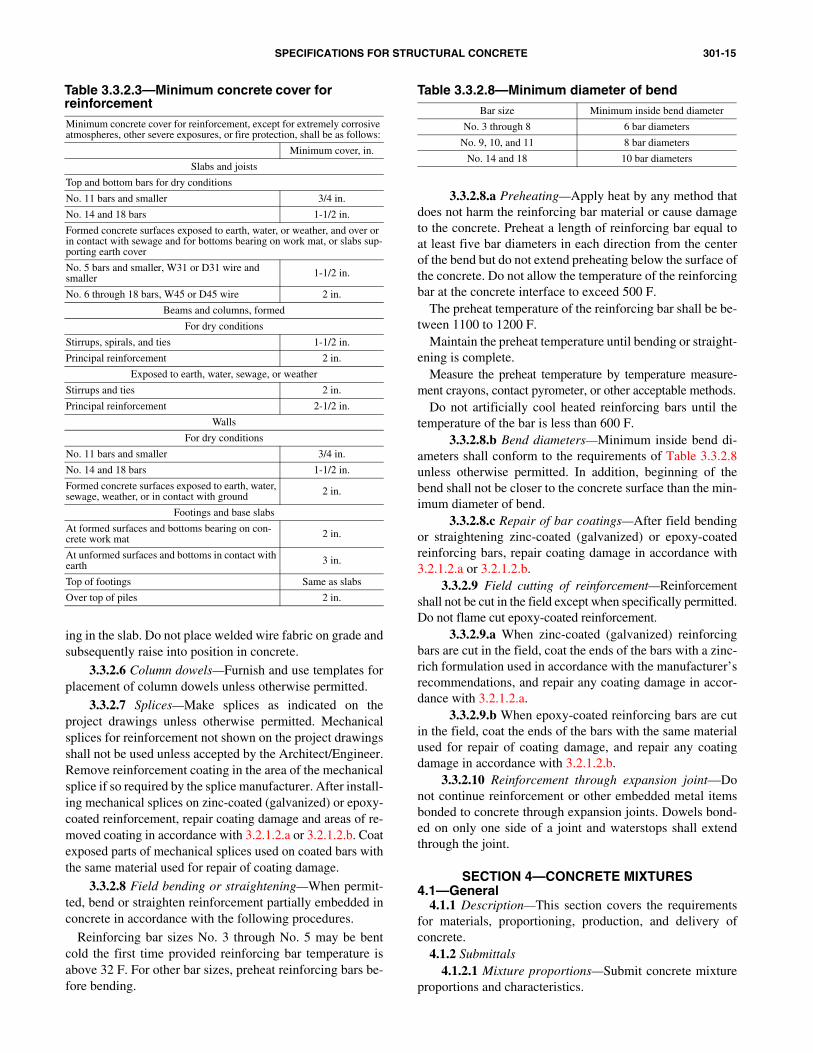
3.3.2.3 Concrete cover—Minimum concrete cover forreinforcement, except for extremely corrosive atmosphere,other severe exposures, or fire protection, shall be as indicatedin Table 3.3.2.3.
For bundled bars, minimum concrete cover shall be equalto the equivalent diameter of the bundle but need not begreater than 2 in.; except the minimum cover shall not be lessthan specified in Table 3.3.2.3. The equivalent diameter ofthe bundle shall be based on a single bar of a diameter de-rived from the equivalent total area.
Tolerances on minimum concrete cover shall meet the re-quirements of ACI 117.
3.3.2.4.a Place reinforcement supported from theground or mud mat on precast concrete reinforcement supports.
3.3.2.4.b Place noncoated reinforcement supportedfrom formwork on reinforcement supports made of concrete,metal, or plastic.
3.3.2.4.c Place zinc-coated (galvanized) reinforce-ment supported from formwork on wire-reinforcement sup-ports that are galvanized, coated with dielectric material, ormade of dielectric material.
3.3.2.4.d Reinforcement and embedded steel items usedwith zinc-coated (galvanized) reinforcement shall be zinc-coated (galvanized) or coated with nonmetallic materials.
3.3.2.4.e Place epoxy-coated reinforcement supportedfrom formwork on coated wire-reinforcement supports or onreinforcement supports made of dielectric material. Usecoatings or materials compatible with concrete.
3.3.2.4.f When precast reinforcement supports with em-bedded tie wires or dowels are used with epoxy-coated rein-forcement, use wires or dowels coated with dielectric material.
3.3.2.4.g Reinforcement used as supports with epoxy-coated reinforcement shall be epoxy coated.
3.3.2.4.h In walls reinforced with epoxy-coated rein-forcement, use spreader bars that are epoxy coated. Pro-prietary combination bar clips and spreaders used in wallswith epoxy-coated reinforcement shall be made of corro-sion-resistant material or coated with dielectric material.
3.3.2.4.i Fasten epoxy-coated reinforcement with tiewires coated with epoxy or other polymer.
3.3.2.5 Welded wire fabric—For slabs on grade, extendwelded wire fabric to within 2 in. of the concrete edge. Lapedges and ends of fabric sheets a minimum of one meshspacing. Unless otherwise permitted, do not extend weldedwire fabric through contraction joints. Support welded wirefabric during placing of concrete to ensure required position-
301-15SPECIFICATIONS FOR STRUCTURAL CONCRETE
Table 3.3.2.3—Minimum concrete cover for reinforcementMinimum concrete cover for reinforcement, except for extremely corrosive atmospheres, other severe exposures, or fire protection, shall be as follows:
Minimum cover, in.
Slabs and joists
Top and bottom bars for dry conditions
No. 11 bars and smaller 3/4 in.
No. 14 and 18 bars 1-1/2 in.
Formed concrete surfaces exposed to earth, water, or weather, and over or in contact with sewage and for bottoms bearing on work mat, or slabs sup-porting earth cover
No. 5 bars and smaller, W31 or D31 wire and smaller 1-1/2 in.
No. 6 through 18 bars, W45 or D45 wire 2 in.
Beams and columns, formed
For dry conditions
Stirrups, spirals, and ties 1-1/2 in.
Principal reinforcement 2 in.
Exposed to earth, water, sewage, or weather
Stirrups and ties 2 in.
Principal reinforcement 2-1/2 in.
Walls
For dry conditions
No. 11 bars and smaller 3/4 in.
No. 14 and 18 bars 1-1/2 in.
Formed concrete surfaces exposed to earth, water, sewage, weather, or in contact with ground 2 in.
Footings and base slabs
At formed surfaces and bottoms bearing on con-crete work mat 2 in.
At unformed surfaces and bottoms in contact with earth 3 in.
Top of footings Same as slabs
Over top of piles 2 in.
ing in the slab. Do not place welded wire fabric on grade andsubsequently raise into position in concrete.
3.3.2.6 Column dowels—Furnish and use templates forplacement of column dowels unless otherwise permitted.
3.3.2.7 Splices—Make splices as indicated on theproject drawings unless otherwise permitted. Mechanicalsplices for reinforcement not shown on the project drawingsshall not be used unless accepted by the Architect/Engineer.Remove reinforcement coating in the area of the mechanicalsplice if so required by the splice manufacturer. After install-ing mechanical splices on zinc-coated (galvanized) or epoxy-coated reinforcement, repair coating damage and areas of re-moved coating in accordance with 3.2.1.2.a or 3.2.1.2.b. Coatexposed parts of mechanical splices used on coated bars withthe same material used for repair of coating damage.
3.3.2.8 Field bending or straightening—When permit-ted, bend or straighten reinforcement partially embedded inconcrete in accordance with the following procedures.
Reinforcing bar sizes No. 3 through No. 5 may be bentcold the first time provided reinforcing bar temperature isabove 32 F. For other bar sizes, preheat reinforcing bars be-fore bending.
3.3.2.8.a Preheating—Apply heat by any method thatdoes not harm the reinforcing bar material or cause damageto the concrete. Preheat a length of reinforcing bar equal toat least five bar diameters in each direction from the centerof the bend but do not extend preheating below the surface ofthe concrete. Do not allow the temperature of the reinforcingbar at the concrete interface to exceed 500 F.
The preheat temperature of the reinforcing bar shall be be-tween 1100 to 1200 F.
Maintain the preheat temperature until bending or straight-ening is complete.
Measure the preheat temperature by temperature measure-ment crayons, contact pyrometer, or other acceptable methods.
Do not artificially cool heated reinforcing bars until thetemperature of the bar is less than 600 F.
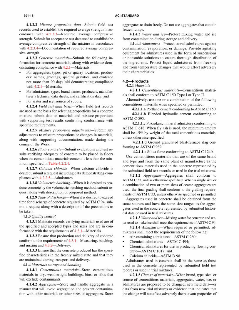
3.3.2.8.b Bend diameters—Minimum inside bend di-ameters shall conform to the requirements of Table 3.3.2.8unless otherwise permitted. In addition, beginning of thebend shall not be closer to the concrete surface than the min-imum diameter of bend.
3.3.2.8.c Repair of bar coatings—After field bendingor straightening zinc-coated (galvanized) or epoxy-coatedreinforcing bars, repair coating damage in accordance with3.2.1.2.a or 3.2.1.2.b.
3.3.2.9 Field cutting of reinforcement—Reinforcementshall not be cut in the field except when specifically permitted.Do not flame cut epoxy-coated reinforcement.
3.3.2.9.a When zinc-coated (galvanized) reinforcingbars are cut in the field, coat the ends of the bars with a zinc-rich formulation used in accordance with the manufacturer’srecommendations, and repair any coating damage in accor-dance with 3.2.1.2.a.
3.3.2.9.b When epoxy-coated reinforcing bars are cutin the field, coat the ends of the bars with the same materialused for repair of coating damage, and repair any coatingdamage in accordance with 3.2.1.2.b.
3.3.2.10 Reinforcement through expansion joint—Donot continue reinforcement or other embedded metal itemsbonded to concrete through expansion joints. Dowels bond-ed on only one side of a joint and waterstops shall extendthrough the joint.
SECTION 4—CONCRETE MIXTURES4.1—General
4.1.1 Description—This section covers the requirementsfor materials, proportioning, production, and delivery ofconcrete.
4.1.2 Submittals4.1.2.1 Mixture proportions—Submit concrete mixture
proportions and characteristics.
Table 3.3.2.8—Minimum diameter of bendBar size Minimum inside bend diameter
No. 3 through 8 6 bar diameters
No. 9, 10, and 11 8 bar diameters
No. 14 and 18 10 bar diameters
301-16 ACI STANDARD
4.2.1 Materials4.2.1.1 Cementitious materials—Cementitious materi-
als shall conform to ASTM C 150 Type I or Type II.Alternatively, use one or a combination of the following
cementitious materials when specified or permitted:
the submitted field test records or used in the trial mixtures.
4.2.1.2 Aggregates—Aggregates shall conform toASTM C 33, unless otherwise specified. When a single size ora combination of two or more sizes of coarse aggregates areused, the final grading shall conform to the grading require-ments of ASTM C 33, unless otherwise specified or permitted.
Aggregates used in concrete shall be obtained from thesame sources and have the same size ranges as the aggre-gates used in the concrete represented by submitted histori-cal data or used in trial mixtures.
4.2.1.3 Water and ice—Mixing water for concrete and wa-ter used to make ice shall meet the requirements of ASTM C 94.
4.2.1.4 Admixtures—When required or permitted, ad-mixtures shall meet the requirements of the following:• Air-entraining admixtures—ASTM C 260;• Chemical admixtures—ASTM C 494;• Chemical admixtures for use in producing flowing con-
crete—ASTM C 1017; and• Calcium chloride—ASTM D 98.
Admixtures used in concrete shall be the same as thoseused in the concrete represented by submitted field testrecords or used in trial mixtures.
4.1.2.2 Mixture proportion data—Submit field testrecords used to establish the required average strength in ac-cordance with 4.2.3.3—Required average compressive
strength. Submit for acceptance test data used to establish theaverage compressive strength of the mixture in accordancewith 4.2.3.4—Documentation of required average compres-sive strength.4.1.2.3 Concrete materials—Submit the following in-formation for concrete materials, along with evidence dem-onstrating compliance with 4.2.1—Materials:• For aggregates: types, pit or quarry locations, produc-
ers’ names, gradings, specific gravities, and evidencenot more than 90 days old demonstrating compliancewith 4.2.1—Materials;
• For admixtures: types, brand names, producers, manufac-turer’s technical data sheets, and certification data; and
• For water and ice: source of supply.4.1.2.4 Field test data basis—When field test records
are used as the basis for selecting proportions for a concretemixture, submit data on materials and mixture proportionswith supporting test results confirming conformance withspecified requirements.
4.1.2.5 Mixture proportion adjustments—Submit anyadjustments to mixture proportions or changes in materials,along with supporting documentation, made during thecourse of the Work.
4.1.2.6 Floor concrete—Submit evaluations and test re-sults verifying adequacy of concrete to be placed in floorswhen the cementitious materials content is less than the min-imum specified in Table 4.2.2.1.
4.1.2.7 Calcium chloride—When calcium chloride isdesired, submit a request including data demonstrating com-pliance with 4.2.2.5—Admixtures.
4.1.2.8 Volumetric batching—When it is desired to pro-duce concrete by the volumetric batching method, submit re-quest along with description of proposed method.
4.1.2.9 Time of discharge—When it is desired to exceedtime for discharge of concrete required by ASTM C 94, sub-mit a request along with a description of the precautions tobe taken.
4.1.3 Quality control4.1.3.1 Maintain records verifying materials used are of
the specified and accepted types and sizes and are in con-formance with the requirements of 4.2.1—Materials.
4.1.3.2 Ensure that production and delivery of concreteconform to the requirements of 4.3.1—Measuring, batching,
and mixing and 4.3.2—Delivery.4.1.3.3 Ensure that the concrete produced has the speci-fied characteristics in the freshly mixed state and that theyare maintained during transport and delivery.
4.1.4 Materials storage and handling4.1.4.1 Cementitious materials—Store cementitious
materials in dry, weathertight buildings, bins, or silos thatwill exclude contaminants.
4.1.4.2 Aggregates—Store and handle aggregate in amanner that will avoid segregation and prevent contamina-tion with other materials or other sizes of aggregates. Store
aggregates to drain freely. Do not use aggregates that containfrozen lumps.
4.1.4.3 Water and ice—Protect mixing water and icefrom contamination during storage and delivery.
4.1.4.4 Admixtures—Protect stored admixtures againstcontamination, evaporation, or damage. Provide agitatingequipment for admixtures used in the form of suspensionsor nonstable solutions to ensure thorough distribution ofthe ingredients. Protect liquid admixtures from freezingand from temperature changes that would affect adverselytheir characteristics.
4.2—Products
4.2.1.1.a Portland cement conforming to ASTM C 150.4.2.1.1.b Blended hydraulic cement conforming to
ASTM C 595.4.2.1.1.c Pozzolanic mineral admixture conforming to
ASTM C 618. When fly ash is used, the minimum amountshall be 15% by weight of the total cementitious materials,unless otherwise specified.
4.2.1.1.d Ground granulated blast-furnace slag con-forming to ASTM C 989.
4.2.1.1.e Silica fume conforming to ASTM C 1240.Use cementitious materials that are of the same brand
and type and from the same plant of manufacture as thecementitious materials used in the concrete represented by
4.2.1.5 Change of materials—When brand, type, size, orsource of cementitious materials, aggregates, water, ice, oradmixtures are proposed to be changed, new field data—ordata from new trial mixtures or evidence that indicates thatthe change will not affect adversely the relevant properties of
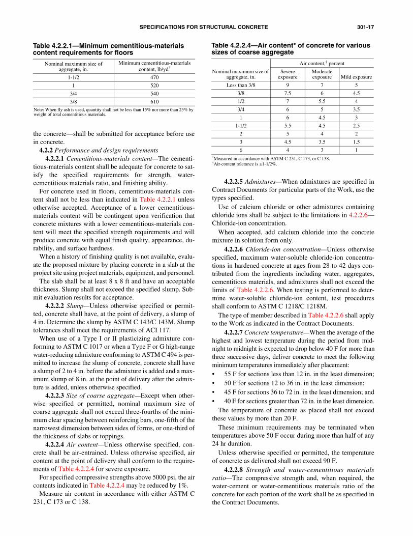
301-17SPECIFICATIONS FOR STRUCTURAL CONCRETE
4.2.2.4 Air content—
mit evaluation results for acceptance. 4.2.2.2 Slump—Unless otherwise specified or permit-
ted, concrete shall have, at the point of delivery, a slump of4 in. Determine the slump by ASTM C 143/C 143M. Slumptolerances shall meet the requirements of ACI 117.
When use of a Type I or II plasticizing admixture con-forming to ASTM C 1017 or when a Type F or G high-rangewater-reducing admixture conforming to ASTM C 494 is per-mitted to increase the slump of concrete, concrete shall havea slump of 2 to 4 in. before the admixture is added and a max-imum slump of 8 in. at the point of delivery after the admix-ture is added, unless otherwise specified.
4.2.2.7 Concrete temperature—When the average of thehighest and lowest temperature during the period from mid-night to midnight is expected to drop below 40 F for more thanthree successive days, deliver concrete to meet the followingminimum temperatures immediately after placement:• 55 F for sections less than 12 in. in the least dimension;• 50 F for sections 12 to 36 in. in the least dimension;• 45 F for sections 36 to 72 in. in the least dimension; and• 40 F for sections greater than 72 in. in the least dimension.
The temperature of concrete as placed shall not exceedthese values by more than 20 F.
These minimum requirements may be terminated whentemperatures above 50 F occur during more than half of any24 hr duration.
Unless otherwise specified or permitted, the temperatureof concrete as delivered shall not exceed 90 F.
4.2.2.6
Table 4.2.2.1—Minimum cementitious-materials content requirements for floors
Nominal maximum size of aggregate, in.
Minimum cementitious-materials content, lb/yd3
1-1/2 470
1 520
3/4 540
3/8 610
Note: When fly ash is used, quantity shall not be less than 15% nor more than 25% by weight of total cementitious materials.
4.2.2.5 Admixtures—When admixtures are specified inContract Documents for particular parts of the Work, use thetypes specified.
Use of calcium chloride or other admixtures containingchloride ions shall be subject to the limitations in 4.2.2.6—Chloride-ion concentration.
When accepted, add calcium chloride into the concretemixture in solution form only.
the concrete—shall be submitted for acceptance before usein concrete.
4.2.2 Performance and design requirements4.2.2.1 Cementitious-materials content—The cementi-
tious-materials content shall be adequate for concrete to sat-isfy the specified requirements for strength, water-cementitious materials ratio, and finishing ability.
For concrete used in floors, cementitious-materials con-tent shall not be less than indicated in Table 4.2.2.1 unlessotherwise accepted. Acceptance of a lower cementitious-materials content will be contingent upon verification thatconcrete mixtures with a lower cementitious-materials con-tent will meet the specified strength requirements and willproduce concrete with equal finish quality, appearance, du-rability, and surface hardness.
When a history of finishing quality is not available, evalu-ate the proposed mixture by placing concrete in a slab at theproject site using project materials, equipment, and personnel.
The slab shall be at least 8 x 8 ft and have an acceptablethickness. Slump shall not exceed the specified slump. Sub-
4.2.2.3 Size of coarse aggregate—Except when other-wise specified or permitted, nominal maximum size ofcoarse aggregate shall not exceed three-fourths of the mini-mum clear spacing between reinforcing bars, one-fifth of thenarrowest dimension between sides of forms, or one-third ofthe thickness of slabs or toppings.
Unless otherwise specified, con-crete shall be air-entrained. Unless otherwise specified, aircontent at the point of delivery shall conform to the require-ments of Table 4.2.2.4 for severe exposure.
Table 4.2.2.4—Air content* of concrete for various sizes of coarse aggregate
Nominal maximum size of aggregate, in.
Air content,† percent
Severe exposure
Moderate exposure Mild exposure
Less than 3/8 9 7 5
3/8 7.5 6 4.5
1/2 7 5.5 4
3/4 6 5 3.5
1 6 4.5 3
1-1/2 5.5 4.5 2.5
2 5 4 2
3 4.5 3.5 1.5
6 4 3 1*Measured in accordance with ASTM C 231, C 173, or C 138.†Air-content tolerance is ±1-1/2%.
For specified compressive strengths above 5000 psi, the aircontents indicated in Table 4.2.2.4 may be reduced by 1%.
Measure air content in accordance with either ASTM C231, C 173 or C 138.
Chloride-ion concentration—Unless otherwisespecified, maximum water-soluble chloride-ion concentra-tions in hardened concrete at ages from 28 to 42 days con-tributed from the ingredients including water, aggregates,cementitious materials, and admixtures shall not exceed thelimits of Table 4.2.2.6. When testing is performed to deter-
mine water-soluble chloride-ion content, test proceduresshall conform to ASTM C 1218/C 1218M.The type of member described in Table 4.2.2.6 shall applyto the Work as indicated in the Contract Documents.
4.2.2.8 Strength and water-cementitious materialsratio—The compressive strength and, when required, thewater-cement or water-cementitious materials ratio of theconcrete for each portion of the work shall be as specified inthe Contract Documents.
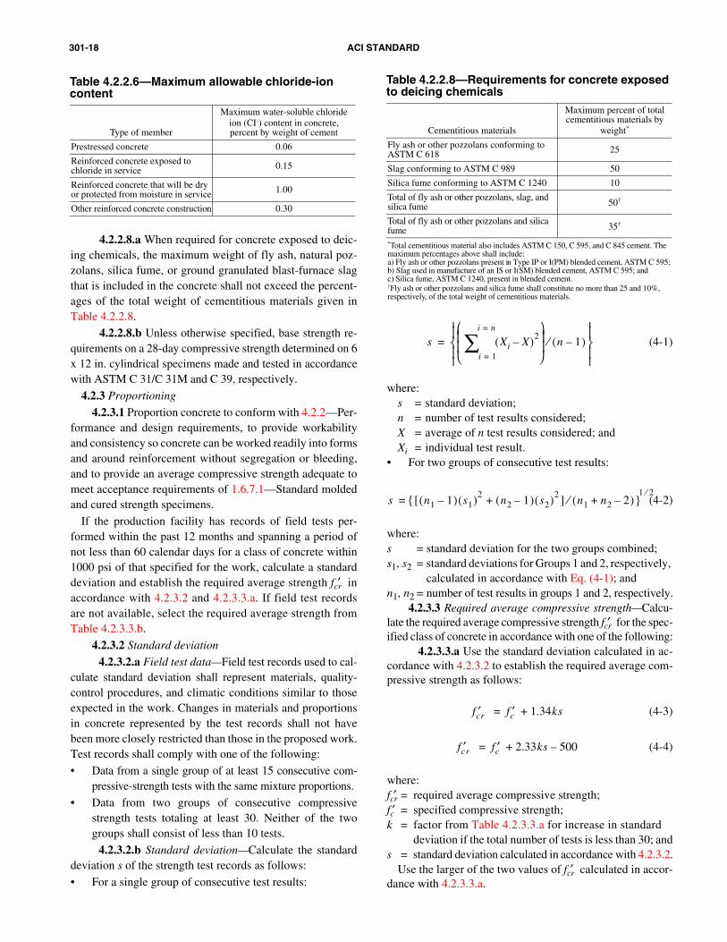
301-18 ACI STANDARD
1 24.2.3.3 Required average compressive strength—Calcu-
late the required average compressive strength fcr′ for the spec-ified class of concrete in accordance with one of the following:
Table 4.2.2.6—Maximum allowable chloride-ion content
Type of member
Maximum water-soluble chloride ion (CI-) content in concrete, percent by weight of cement
Prestressed concrete 0.06
Reinforced concrete exposed to chloride in service 0.15
Reinforced concrete that will be dry or protected from moisture in service 1.00
Other reinforced concrete construction 0.30
4.2.2.8.a When required for concrete exposed to deic-ing chemicals, the maximum weight of fly ash, natural poz-zolans, silica fume, or ground granulated blast-furnace slagthat is included in the concrete shall not exceed the percent-ages of the total weight of cementitious materials given inTable 4.2.2.8.
4.2.2.8.b Unless otherwise specified, base strength re-quirements on a 28-day compressive strength determined on 6x 12 in. cylindrical specimens made and tested in accordancewith ASTM C 31/C 31M and C 39, respectively.
4.2.3 Proportioning
4.2.3.1 Proportion concrete to conform with 4.2.2—Per-formance and design requirements, to provide workabilityand consistency so concrete can be worked readily into formsand around reinforcement without segregation or bleeding,and to provide an average compressive strength adequate tomeet acceptance requirements of 1.6.7.1—Standard moldedand cured strength specimens.
If the production facility has records of field tests per-formed within the past 12 months and spanning a period ofnot less than 60 calendar days for a class of concrete within1000 psi of that specified for the work, calculate a standarddeviation and establish the required average strength fcr′ inaccordance with 4.2.3.2 and 4.2.3.3.a. If field test recordsare not available, select the required average strength fromTable 4.2.3.3.b.
4.2.3.2 Standard deviation
4.2.3.2.a Field test data—Field test records used to cal-culate standard deviation shall represent materials, quality-control procedures, and climatic conditions similar to thoseexpected in the work. Changes in materials and proportionsin concrete represented by the test records shall not havebeen more closely restricted than those in the proposed work.Test records shall comply with one of the following:
• Data from a single group of at least 15 consecutive com-pressive-strength tests with the same mixture proportions.
• Data from two groups of consecutive compressivestrength tests totaling at least 30. Neither of the twogroups shall consist of less than 10 tests.
4.2.3.2.b Standard deviation—Calculate the standarddeviation s of the strength test records as follows:
• For a single group of consecutive test results:
(4-1)
where:s = standard deviation;n = number of test results considered;X = average of n test results considered; andXi = individual test result.
• For two groups of consecutive test results:
(4-2)
where:s = standard deviation for the two groups combined;s1, s2 = standard deviations for Groups 1 and 2, respectively,
calculated in accordance with Eq. (4-1); andn , n = number of test results in groups 1 and 2, respectively.
s Xi X–( )2
i 1=
i n=
∑
n 1–( )⁄
=
s n1 1–( ) s1( )2[ n2 1–( ) s2( )2 ] n1 n2 2–+( )⁄+{ }1 2⁄
=
Table 4.2.2.8—Requirements for concrete exposed to deicing chemicals
Cementitious materials
Maximum percent of total cementitious materials by
weight*
Fly ash or other pozzolans conforming to ASTM C 618 25
Slag conforming to ASTM C 989 50
Silica fume conforming to ASTM C 1240 10
Total of fly ash or other pozzolans, slag, and silica fume 50†
Total of fly ash or other pozzolans and silica fume 35†
*Total cementitious material also includes ASTM C 150, C 595, and C 845 cement. The maximum percentages above shall include:a) Fly ash or other pozzolans present in Type IP or I(PM) blended cement, ASTM C 595;b) Slag used in manufacture of an IS or I(SM) blended cement, ASTM C 595; andc) Silica fume, ASTM C 1240, present in blended cement.†Fly ash or other pozzolans and silica fume shall constitute no more than 25 and 10%, respectively, of the total weight of cementitious materials.
4.2.3.3.a Use the standard deviation calculated in ac-cordance with 4.2.3.2 to establish the required average com-pressive strength as follows:
(4-3)
(4-4)
where:fcr′ = required average compressive strength;fc′ = specified compressive strength;k = factor from Table 4.2.3.3.a for increase in standard
fcr′ fc′ 1.34ks+=
fcr′ fc′ 2.33ks 500–+=
deviation if the total number of tests is less than 30; ands = standard deviation calculated in accordance with 4.2.3.2.
Use the larger of the two values of fcr′ calculated in accor-dance with 4.2.3.3.a.
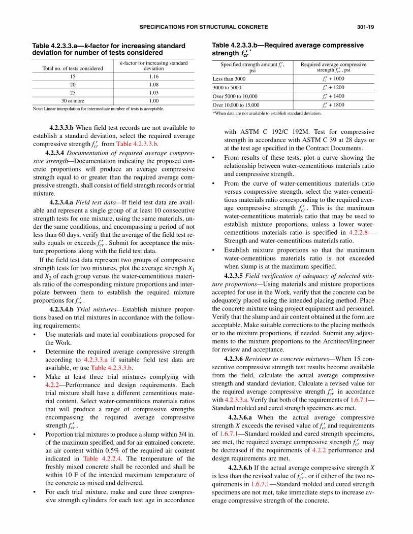
301-19SPECIFICATIONS FOR STRUCTURAL CONCRETE
Table 4.2.3.3.b—Required average compressive strength fcr′′′′ *
Specified strength amount fc′ ,psi
Required average compressive strength fcr′ , psi
Less than 3000 fc′ + 1000
3000 to 5000 fc′ + 1200
Over 5000 to 10,000 fc′ + 1400
Over 10,000 to 15,000 fc′ + 1800
*When data are not available to establish standard deviation.
Table 4.2.3.3.a—k-factor for increasing standard deviation for number of tests considered
Total no. of tests consideredk-factor for increasing standard
deviation
15 1.16
20 1.08
25 1.03
30 or more 1.00
Note: Linear interpolation for intermediate number of tests is acceptable.
4.2.3.3.b When field test records are not available toestablish a standard deviation, select the required averagecompressive strength fcr′ from Table 4.2.3.3.b.
4.2.3.4 Documentation of required average compres-sive strength—Documentation indicating the proposed con-crete proportions will produce an average compressivestrength equal to or greater than the required average com-pressive strength, shall consist of field strength records or trialmixture.
4.2.3.4.a Field test data—If field test data are avail-able and represent a single group of at least 10 consecutivestrength tests for one mixture, using the same materials, un-der the same conditions, and encompassing a period of notless than 60 days, verify that the average of the field test re-sults equals or exceeds fcr′ . Submit for acceptance the mix-ture proportions along with the field test data.
If the field test data represent two groups of compressivestrength tests for two mixtures, plot the average strength X1and X2 of each group versus the water-cementitious materi-als ratio of the corresponding mixture proportions and inter-polate between them to establish the required mixtureproportions for fcr′ .
4.2.3.4.b Trial mixtures—Establish mixture propor-tions based on trial mixtures in accordance with the follow-ing requirements:• Use materials and material combinations proposed for
the Work.• Determine the required average compressive strength
according to 4.2.3.3.a if suitable field test data areavailable, or use Table 4.2.3.3.b.
• Make at least three trial mixtures complying with4.2.2—Performance and design requirements. Eachtrial mixture shall have a different cementitious mate-rial content. Select water-cementitious materials ratiosthat will produce a range of compressive strengthsencompassing the required average compressivestrength fcr′ .
• Proportion trial mixtures to produce a slump within 3/4 in.of the maximum specified, and for air-entrained concrete,an air content within 0.5% of the required air contentindicated in Table 4.2.2.4. The temperature of thefreshly mixed concrete shall be recorded and shall bewithin 10 F of the intended maximum temperature ofthe concrete as mixed and delivered.
• For each trial mixture, make and cure three compres-sive strength cylinders for each test age in accordance
with ASTM C 192/C 192M. Test for compressivestrength in accordance with ASTM C 39 at 28 days orat the test age specified in the Contract Documents.
• From results of these tests, plot a curve showing therelationship between water-cementitious materials ratioand compressive strength.
• From the curve of water-cementitious materials ratioversus compressive strength, select the water-cementi-tious materials ratio corresponding to the required aver-age compressive strength fcr′ . This is the maximumwater-cementitious materials ratio that may be used toestablish mixture proportions, unless a lower water-cementitious materials ratio is specified in 4.2.2.8—Strength and water-cementitious materials ratio.
• Establish mixture proportions so that the maximumwater-cementitious materials ratio is not exceededwhen slump is at the maximum specified.
4.2.3.5 Field verification of adequacy of selected mix-ture proportions—Using materials and mixture proportionsaccepted for use in the Work, verify that the concrete can beadequately placed using the intended placing method. Placethe concrete mixture using project equipment and personnel.Verify that the slump and air content obtained at the form areacceptable. Make suitable corrections to the placing methodsor to the mixture proportions, if needed. Submit any adjust-ments to the mixture proportions to the Architect/Engineerfor review and acceptance.
4.2.3.6 Revisions to concrete mixtures—When 15 con-secutive compressive strength test results become availablefrom the field, calculate the actual average compressivestrength and standard deviation. Calculate a revised value forthe required average compressive strength fcr′ in accordancewith 4.2.3.3.a. Verify that both of the requirements of 1.6.7.1—Standard molded and cured strength specimens are met.
4.2.3.6.a When the actual average compressivestrength X exceeds the revised value of fcr′ and requirementsof 1.6.7.1—Standard molded and cured strength specimens,are met, the required average compressive strength fcr′ maybe decreased if the requirements of 4.2.2 performance anddesign requirements are met.
4.2.3.6.b If the actual average compressive strength Xis less than the revised value of fcr′ , or if either of the two re-quirements in 1.6.7.1—Standard molded and cured strengthspecimens are not met, take immediate steps to increase av-erage compressive strength of the concrete.
301-20 ACI STANDARD
4.3.1 Measuring, batching, and mixing—Production facil-ities shall produce concrete of the specified quality and con-forming to the requirements of this Reference Specification.
4.3.2 Delivery—Concrete shall possess the specified char-acteristics in the freshly mixed state at the point of placing.Transport and deliver concrete in equipment conforming tothe requirements of ASTM C 94.
4.2.3.6.c Submit revised mixture proportions for ac-ceptance prior to placing in the work.
4.3—Execution
4.3.1.1 Ready-mixed and site-produced concrete—Un-less otherwise specified, measure, batch, and mix concretematerials and concrete in conformance with ASTM C 94.
4.3.1.2 Concrete produced by volumetric batching andcontinuous mixing—When concrete made by volumetricbatching and continuous mixing is acceptable, it shall con-form to the requirements of ASTM C 685 and shall satisfythe requirements of this Reference Specification.
4.3.1.3 Prepackaged dry materials used in concrete—Ifpackaged dry-combined materials are used, they shall con-form to the requirements of ASTM C 387, and shall satisfythe requirements of this Reference Specification.
4.3.2.1 Slump adjustment—When concrete arrives at thepoint of delivery with a slump below that which will result inthe specified slump at the point of placement and is unsuitablefor placing at that slump, the slump may be adjusted to the re-quired value by adding water up to the amount allowed in theaccepted mixture proportions unless otherwise specified bythe Architect/Engineer. Addition of water shall be in accor-dance with ASTM C 94. Do not exceed the specified water-ce-mentitious materials ratio or slump. Do not add water toconcrete delivered in equipment not acceptable for mixing.
After plasticizing or high-range water-reducing admix-tures are added to the concrete at the site to achieve flowableconcrete, do not add water to the concrete.
Measure slump and air content of air-entrained concreteafter slump adjustment, to verify compliance with specifiedrequirements.
4.3.2.2 Time of discharge—Time for completion of dis-charge shall comply with ASTM C 94, unless otherwise per-mitted. When discharge is permitted after more than 90 minhave elapsed since batching or after the drum has revolved300 revolutions, verify that air content of air-entrained con-crete, slump, and temperature of concrete are as specified.
SECTION 5—HANDLING, PLACING, AND CONSTRUCTING
5.1—General5.1.1 Description—This section covers the production of
cast-in-place structural concrete. Included are methods andprocedures for obtaining quality concrete through proper han-dling, placing, finishing, curing, and repair of surface defects.
5.1.2 Submittals5.1.2.1 Submit the following data unless otherwise specified:
a. Field control test reports—Maintain and submit accu-rate records of test and inspection reports.
b. Conveying equipment—Submit description of convey-ing equipment.
c. Temperature measurement—Submit proposed methodof measuring concrete surface temperature changes.
d. Repair methods—When stains, rust, efflorescence, andsurface deposits must be removed as described in 5.3.7.7,
submit the proposed method of removal.e. Qualifications of finishers—Submit qualifications of thefinishing contractor and the finishers who will perform theWork.
5.1.2.2 Submit the following data when required:a. Drawings and data—Submit shop drawings and data for
review as required by the Contract Documents.b. Placement notification—When Contract Documents re-
quire advance notification of concrete placement, submit no-tification at least 24 hr in advance.
c. Preplacement requirements—Submit, when required,request for acceptance of preplacement activities.
d. Wet-weather placement—When placement is scheduledduring wet weather, submit, when required, request for ac-ceptance of protection.
e. Hot-weather placement—When placement of concreteexceeding 90 F is desired as described in 5.3.2.1.c, submit,
when required, request for placement along with proposedprecautions.f. Matching sample finish—When required by ContractDocuments, submit sample finish as described in 5.3.3.2.
g. Exposed-aggregate surface—When an exposed-aggre-gate surface is specified and a chemical retarder is proposedto be used, submit specification and manufacturer’s data forthe retarder and the proposed method of using retarder.
5.1.2.3 Submit the following data when alternatives areproposed:
a. Construction joints—Submit information for accep-tance of proposed location and treatment of constructionjoints proposed but not indicated on the project drawings.
b. Two-course slabs—When a bonding agent other thancement grout is proposed, submit specification and manufac-turer’s data for bonding agent.
c. Underwater placement—When underwater placement isplanned, submit request for acceptance of proposed method.
d. Contraction joints—When contraction joints other thanthose indicated on the Contract Documents are proposed,submit request of location.
e. Moisture-preserving method—When a moisture-pre-serving method other than specified in 5.3.6.4.a through e is
proposed, submit request of the proposed method.f. Coated ties—When coated form ties described in 5.3.7.2are proposed to preclude the requirement to patch tie holes,submit proposed coated tie description.
g. Repair materials—When a repair material described in5.2.1.3—Proprietary patching materials is proposed, submitthe repair material specification, manufacturer’s data on theproposed patching material, and the proposed preparationand application procedure.
5.1.3 Delivery, storage, and handling
301-21SPECIFICATIONS FOR STRUCTURAL CONCRETE
5.3.2.1.c Hot weather—The temperature of concreteas placed shall not exceed 90 F unless otherwise permitted.Loss of slump, flash set, or cold joints due to temperature ofconcrete as placed will not be acceptable. When temperatureof concrete exceeds 90 F, obtain acceptance, when required,of proposed precautionary measures. When temperature of steelreinforcement, embedments, or forms is greater than 120 F, fogsteel reinforcement, embedments, and forms with water im-mediately before placing concrete. Remove standing waterbefore placing concrete.
5.1.3.1 Delivery—Place concrete within the time limitsrequired in 4.3.2.2.
5.1.3.2 Storage and handling—Store and handle prod-ucts to retain original quality. Do not use products stored be-yond the manufacturer’s recommended shelf life.
5.2—Products5.2.1 Materials
5.2.1.1 Curing compounds—Use curing compoundsthat conform to ASTM C 309 or ASTM C 1315.
5.2.1.2 Waterproof sheet materials—Use waterproofsheet materials that conform to ASTM C 171.
5.2.1.3 Proprietary patching materials—Use accept-able proprietary patching materials complying with5.3.7.6—Repair materials other than site-mixed portland-ce-ment mortar.
5.2.1.4 Bonding grout—Use bonding grout in accor-dance with 5.3.7.4—Preparation of bonding grout.
5.2.1.5 Site-mixed portland-cement repair mortar—Userepair mortar in accordance with 5.3.7.5—Preparation of
site-mixed portland-cement repair mortar.5.2.2 Performance and design requirements5.2.2.1 Construction joints—Make and locate construc-
tion joints that are proposed, but not indicated on the projectdrawings, in accordance with 2.2.2.5. Do not impair strengthof the structures with construction joints.
5.3—Execution5.3.1 Preparation
5.3.1.1 Do not place concrete until data on materials andmixture proportions are accepted.
5.3.1.2 Remove hardened concrete and foreign materi-als from the inner surfaces of conveying equipment.
5.3.1.3 Before placing concrete in forms, complete thefollowing:• Comply with formwork requirements specified in
Section 2—Formwork and formwork accessories;• Remove snow, ice, frost, water, and other foreign materials
from surfaces, including reinforcement and embeddeditems, against which concrete will be placed;
• Comply with reinforcing steel placement requirementsspecified in Section 3—Reinforcement and reinforce-ment supports;
• Position and secure in place expansion joint materials,anchors, and other embedded items; and
• Obtain acceptance of finished preparation.5.3.1.4 Before placing a concrete slab on grade, clean for-
eign materials from the subgrade and complete the following:• Subgrade shall be well drained and of uniform load-
bearing nature;• In-place density of subgrade soils shall be uniform
throughout the area and at least the minimum requiredby Contract Documents;
• Subgrade shall be free from frost or ice; and • Subgrade shall be moist with no free water and no
muddy or soft spots.
5.3.1.5 When high ambient temperatures necessitateprotection of concrete immediately after placing or finishing,make provisions in advance of concrete placement for wind-breaks, shading, fogging, sprinkling, ponding, or wet covering.
5.3.1.6 During ambient temperature conditions de-scribed in 4.2.2.7—Concrete temperature, make provisionsin advance of concrete placement to maintain the tempera-ture of the concrete as specified in Section 5.3.2.1.b. Useheating, covering, or other means adequate to maintain re-quired temperature without overheating or drying of con-crete due to concentration of heat. Do not use combustionheaters unless precautions are taken to prevent exposure ofthe concrete to exhaust gases containing carbon dioxide.
5.3.2 Placement of concrete5.3.2.1 Weather considerations
5.3.2.1.a Wet weather—Do not begin to place con-crete while rain, sleet, or snow is falling unless adequate pro-tection is provided and, when required, acceptance ofprotection is obtained.
Do not allow rain water to increase mixing water or todamage the surface of the concrete.
5.3.2.1.b Cold weather—Concrete temperatures andambient temperatures shall meet minimum temperature re-quirements of 4.2.2.7—Concrete temperature.
5.3.2.2 Conveying—Convey concrete from mixer to theplace of final deposit rapidly by methods that prevent segre-gation or loss of ingredients and will ensure the requiredquality of concrete. Do not use aluminum pipes or chutes.
5.3.2.3 Conveying equipment—Use acceptable convey-ing equipment of a size and design that will prevent coldjoints from occurring. Clean conveying equipment beforeeach placement.
5.3.2.3.a Use belt conveyors that are horizontal or ata slope that will not cause excessive segregation or loss ofingredients. Protect concrete to minimize drying and effectsof temperature rise. Use an acceptable discharge baffle orhopper at the discharge end to prevent segregation. Do notallow mortar to adhere to the return length of the belt.
5.3.2.3.b Use metal or metal lined chutes havingrounded bottoms, and sloped between one vertical to twohorizontal and one vertical to three horizontal. Chutes morethan 20 ft long and chutes not meeting slope requirementsmay be used, provided the discharge is into a hopper beforedistributing into the forms.
5.3.2.3.c Use pumping conveying equipment that per-mits placement rates that avoid cold joints and prevent seg-regation in discharge of pumped concrete.
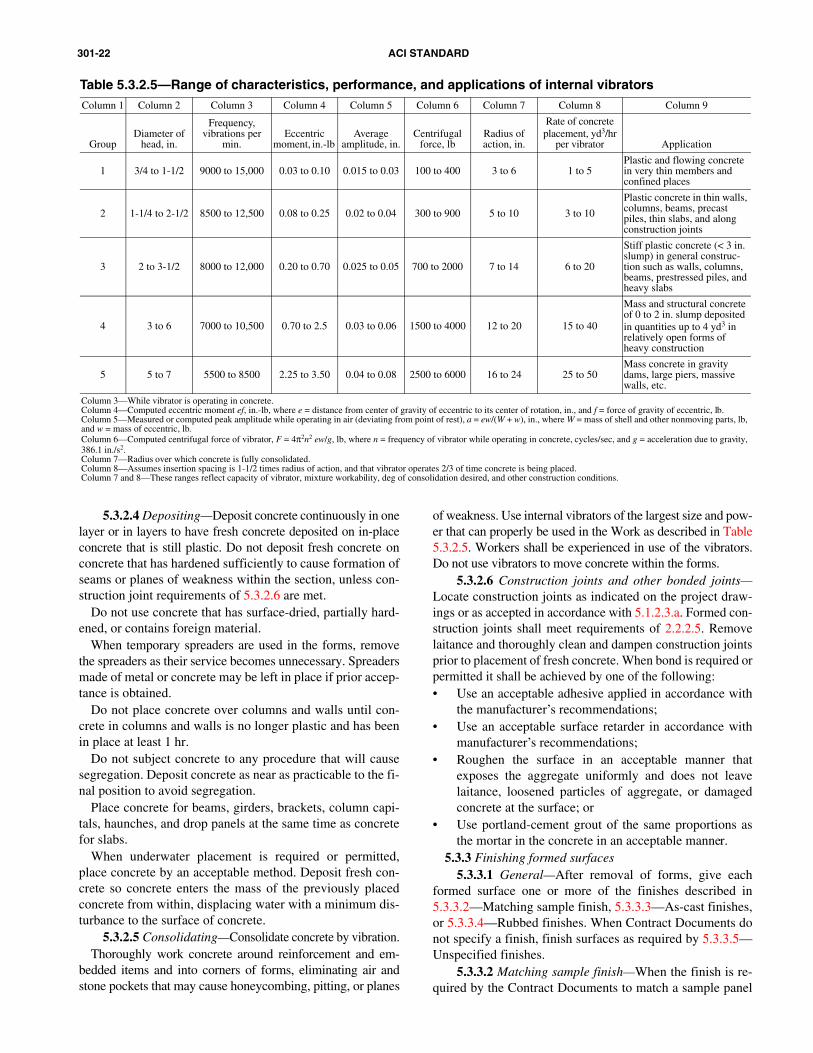
301-22 ACI STANDARD
5.3.3 Finishing formed surfaces
5.3.2.6
5.3.3.2 Matching sample finish—When the finish is re-quired by the Contract Documents to match a sample panel
Table 5.3.2.5—Range of characteristics, performance, and applications of internal vibratorsColumn 1 Column 2 Column 3 Column 4 Column 5 Column 6 Column 7 Column 8 Column 9
GroupDiameter of
head, in.
Frequency, vibrations per
min.Eccentric
moment, in.-lb Average
amplitude, in.Centrifugal
force, lbRadius of action, in.
Rate of concrete placement, yd3/hr
per vibrator Application
1 3/4 to 1-1/2 9000 to 15,000 0.03 to 0.10 0.015 to 0.03 100 to 400 3 to 6 1 to 5Plastic and flowing concrete in very thin members and confined places
2 1-1/4 to 2-1/2 8500 to 12,500 0.08 to 0.25 0.02 to 0.04 300 to 900 5 to 10 3 to 10
Plastic concrete in thin walls, columns, beams, precast piles, thin slabs, and along construction joints
3 2 to 3-1/2 8000 to 12,000 0.20 to 0.70 0.025 to 0.05 700 to 2000 7 to 14 6 to 20
Stiff plastic concrete (< 3 in. slump) in general construc-tion such as walls, columns, beams, prestressed piles, and heavy slabs
4 3 to 6 7000 to 10,500 0.70 to 2.5 0.03 to 0.06 1500 to 4000 12 to 20 15 to 40
Mass and structural concrete of 0 to 2 in. slump deposited in quantities up to 4 yd3 in relatively open forms of heavy construction
5 5 to 7 5500 to 8500 2.25 to 3.50 0.04 to 0.08 2500 to 6000 16 to 24 25 to 50Mass concrete in gravity dams, large piers, massive walls, etc.
Column 3—While vibrator is operating in concrete.Column 4—Computed eccentric moment ef, in.-lb, where e = distance from center of gravity of eccentric to its center of rotation, in., and f = force of gravity of eccentric, lb.Column 5—Measured or computed peak amplitude while operating in air (deviating from point of rest), a = ew/(W + w), in., where W = mass of shell and other nonmoving parts, lb, and w = mass of eccentric, lb.Column 6—Computed centrifugal force of vibrator, F = 4π2n2 ew/g, lb, where n = frequency of vibrator while operating in concrete, cycles/sec, and g = acceleration due to gravity, 386.1 in./s2.Column 7—Radius over which concrete is fully consolidated.Column 8—Assumes insertion spacing is 1-1/2 times radius of action, and that vibrator operates 2/3 of time concrete is being placed.Column 7 and 8—These ranges reflect capacity of vibrator, mixture workability, deg of consolidation desired, and other construction conditions.
5.3.2.4 Depositing—Deposit concrete continuously in onelayer or in layers to have fresh concrete deposited on in-placeconcrete that is still plastic. Do not deposit fresh concrete onconcrete that has hardened sufficiently to cause formation ofseams or planes of weakness within the section, unless con-struction joint requirements of 5.3.2.6 are met.
Do not use concrete that has surface-dried, partially hard-ened, or contains foreign material.
When temporary spreaders are used in the forms, removethe spreaders as their service becomes unnecessary. Spreadersmade of metal or concrete may be left in place if prior accep-tance is obtained.
Do not place concrete over columns and walls until con-crete in columns and walls is no longer plastic and has beenin place at least 1 hr.
Do not subject concrete to any procedure that will causesegregation. Deposit concrete as near as practicable to the fi-nal position to avoid segregation.
Place concrete for beams, girders, brackets, column capi-tals, haunches, and drop panels at the same time as concretefor slabs.
When underwater placement is required or permitted,place concrete by an acceptable method. Deposit fresh con-crete so concrete enters the mass of the previously placedconcrete from within, displacing water with a minimum dis-turbance to the surface of concrete.
5.3.2.5 Consolidating—Consolidate concrete by vibration.Thoroughly work concrete around reinforcement and em-
bedded items and into corners of forms, eliminating air andstone pockets that may cause honeycombing, pitting, or planes
of weakness. Use internal vibrators of the largest size and pow-er that can properly be used in the Work as described in Table5.3.2.5. Workers shall be experienced in use of the vibrators.Do not use vibrators to move concrete within the forms.
Construction joints and other bonded joints—Locate construction joints as indicated on the project draw-ings or as accepted in accordance with 5.1.2.3.a. Formed con-struction joints shall meet requirements of 2.2.2.5. Removelaitance and thoroughly clean and dampen construction jointsprior to placement of fresh concrete. When bond is required orpermitted it shall be achieved by one of the following:• Use an acceptable adhesive applied in accordance with
the manufacturer’s recommendations;• Use an acceptable surface retarder in accordance with
manufacturer’s recommendations;• Roughen the surface in an acceptable manner that
exposes the aggregate uniformly and does not leavelaitance, loosened particles of aggregate, or damagedconcrete at the surface; or
• Use portland-cement grout of the same proportions asthe mortar in the concrete in an acceptable manner.
5.3.3.1 General—After removal of forms, give eachformed surface one or more of the finishes described in5.3.3.2—Matching sample finish, 5.3.3.3—As-cast finishes,
or 5.3.3.4—Rubbed finishes. When Contract Documents donot specify a finish, finish surfaces as required by 5.3.3.5—Unspecified finishes.
301-23SPECIFICATIONS FOR STRUCTURAL CONCRETE
5.3.4 Finishing unformed surfaces
5.3.3.5 Unspecified finishes—When a specific finish isnot specified in Contract Documents for a concrete surface,apply the following finishes:
• Rough-form finish on concrete surfaces not exposed topublic view; and
• Smooth-form finish on concrete surfaces exposed topublic view.
furnished to the Contractor, reproduce the sample finish onan area at least 100 ft2 in a location designated by the Archi-tect/Engineer. Obtain acceptance before proceeding withthat finish in the specified locations.
5.3.3.3 As-cast finishes—Use form-facing materialsmeeting the requirements of 2.2.1.1—Form-facing materials.Unless otherwise specified, produce as-cast form finishes inaccordance with the following requirements:
5.3.3.4 Rubbed finishes—Remove forms as early as per-mitted by 2.3.2—Removal of forms. Produce one of the fol-lowing finishes on concrete specified to have a smooth formfinish:
5.3.3.3.a Rough-form finish—Patch tie holes and de-fects. Chip or rub off fins exceeding 1/2 in. in height. Leavesurfaces with the texture imparted by the forms.
5.3.3.3.b Smooth-form finish—Patch tie holes and de-fects. Remove fins exceeding 1/8 in. in height.
5.3.3.3.c Architectural finishes—Produce architectur-al finishes including special textured finishes, exposed-ag-gregate finish, and aggregate transfer finish in accordancewith Section 6—Architectural concrete.
5.3.3.4.a Smooth-rubbed finish—Remove forms asearly as permitted by Section 2—Formwork and formworkaccessories, and perform necessary patching. Produce finishon newly hardened concrete no later than the day followingformwork removal. Wet the surface and rub it with carbo-rundum brick or other abrasive until uniform color and tex-ture are produced. Use no cement grout other than cementpaste drawn from the concrete itself by the rubbing process.
5.3.3.4.b Grout-cleaned finish—Begin cleaning oper-ations after contiguous surfaces to be cleaned are completedand accessible. Do not clean surfaces as work progresses.Wet the surface and apply grout consisting of one part port-land cement and one and one-half parts fine sand withenough water to produce the consistency of thick paint. Addwhite cement as needed to match color of surrounding con-crete. Scrub grout into voids, and remove excess grout.When grout whitens, rub the surface and keep the surfacedamp for 36 hr afterward.
5.3.3.4.c Cork-floated finish—Perform necessary re-pairs. Remove ties, burrs, and fins. Wet the surface and ap-ply stiff grout of one part portland cement and one part finesand, filling voids. Add white cement as needed to matchcolor of surrounding concrete. Use enough water to producea stiff consistency. Compress grout into voids by grindingthe surface with a slow-speed grinder. Produce the final fin-ish with cork float, using a swirling motion.
5.3.4.1 Placement—Place concrete at a rate that allowsspreading, straightedging, and darbying or bullfloating be-fore bleed water appears.
Strike smooth the top of walls, buttresses, horizontal off-sets, and other similar unformed surfaces and float them to atexture consistent with finish of adjacent formed surface.
Finish slab surfaces in accordance with one of the finishesin 5.3.4.2—Finishes and tolerances, as designated in theContract Documents. Use qualified flatwork finishers ac-ceptable to the Architect/Engineer.
5.3.4.2 Finishes and tolerances
5.3.4.2.a Scratched finish—Place, consolidate, strikeoff, and level concrete, eliminating high spots and low spots.Roughen the surface with stiff brushes or rakes before the fi-nal set. Produce a finish that will meet conventional bull-floated tolerance requirements of ACI 117.
5.3.4.2.b Floated finish—Place, consolidate, strikeoff, and level concrete, eliminating high spots and low spots.Do not work concrete further until it is ready for floating. Be-gin floating with a hand float, a bladed power float equippedwith float shoes, or a powered disk float when the bleed watersheen has disappeared and the surface has stiffened suffi-ciently to permit the operation. Produce a finish that will meetconventional straightedged tolerance requirements of ACI117, then refloat the slab immediately to a uniform texture.
5.3.4.2.c Troweled finish—Float concrete surface,then power-trowel the surface. Hand-trowel the surfacesmooth and free of trowel marks. Continue hand-troweling untila ringing sound is produced as the floor is troweled. Tolerancefor concrete floors shall be conventional straightedged toler-ance in accordance with ACI 117, unless otherwise specified.
5.3.4.2.d Broom or belt finish—Immediately after con-crete has received a floated finish, give the concrete surfacea coarse transverse scored texture by drawing a broom orburlap belt across the surface.
5.3.4.2.e Dry-shake finish—Blend metallic or mineralaggregate specified in Contract Documents with portland ce-ment in the proportions recommended by the aggregate man-ufacturer, or use bagged, premixed material specified inContract Documents as recommended by the manufacturer.Float-finish the concrete surface. Apply approximately two-thirds of the blended material required for coverage to thesurface by a method that ensures even coverage without seg-regation. Float-finish the surface after application of the firstdry-shake. Apply the remaining dry-shake material at rightangles to the first application and in locations necessary toprovide the specified minimum thickness. Begin final floatingand finishing immediately after application of the dry-shake.
After selected material is embedded by the two floatings,complete operation with a broomed, floated, or troweled fin-ish, as specified in the Contract Documents.
5.3.4.2.f Heavy-duty topping for two-course slabs—For heavy-duty topping mixture, use the materials and meth-ods specified in Contract Documents. Place and consolidateconcrete for the base slab, and screed concrete to the speci-fied depth below the top of the finished surface.
301-24 ACI STANDARD
5.3.4.3 Measuring tolerances for slabs
Topping placed the same day as the base slab shall beplaced as soon as bleed water in the base slab has disap-peared and the surface will support a person without appre-ciable indentation.
When topping placement is deferred, brush the surfacewith a coarse wire broom to remove laitance and scratch thesurface when concrete is plastic. Wet-cure the base slab atleast 3 days. Before placing the topping, clean the base slabsurface thoroughly of contaminants and loose mortar or aggre-gate. Dampen the surface, leaving it free of standing water.
Immediately before placing topping, scrub into the slabsurface a coat of bonding grout consisting of equal parts ofcement and fine sand with enough water to make a creamymixture. Do not allow grout to set or dry before topping isplaced. Bonding agents other than cement grout may be usedwith prior acceptance.
Spread, compact, and float the topping mixture. Check forflatness of surface and complete operation with a floated, trow-eled, or broom finish as specified in the Contract Documents.
5.3.4.2.g Topping for two-course slab not intended forheavy-duty service—Preparation of base slab, selection oftopping material, mixing, placing, consolidating, and finish-ing operations shall be as specified in Section 5.3.4.2.f—Heavy-duty topping for two-course slabs, except that the ag-gregate need not be selected for special wear resistance.
5.3.4.2.h Nonslip finish—Where a nonslip finish is re-quired, give the surface a broom or belt finish or a dry-shakeapplication of crushed aluminum oxide or other abrasive par-ticles, as specified in the Contract Documents. Rate of appli-cation shall be not less than 25 lb/100 ft2.
5.3.4.2.i Exposed-aggregate finish—Immediately aftersurface of the concrete has been leveled to meet the conven-tional straightedged tolerance requirements of ACI 117 andthe bleed water sheen has disappeared, spread aggregate ofthe color and size specified in Contract Documents uniform-ly over the surface to provide complete coverage to a depthof one stone.
Tamp the aggregate lightly to embed aggregate in the sur-face. Float the surface until the embedded stone is fully coatedwith mortar and the surface has been finished to meet theconventional straightedged tolerance requirements of ACI117. After the matrix has hardened sufficiently to preventdislodgment of the aggregate, apply water carefully andbrush the surface with a fine-bristled brush to expose the ag-gregate without dislodging it.
An acceptable chemical retarder sprayed on freshly floatedconcrete surface may be used to extend the working time forthe exposure of aggregate.
5.3.4.2.j Nonspecified finish—When the type of finishis not specified in Contract Documents, use one of the fol-lowing appropriate finishes and accompanying tolerances.• Scratched finish. For surfaces intended to receive
bonded cementitious mixtures;• Floated finish. For walks, drives, steps, ramps, and for
surfaces intended to receive waterproofing, roofing,insulation, or sand-bed terrazzo; or
• Troweled finish. For floors intended as walking surfaces,
floors in manufacturing, storage, and warehousing areas,or for reception of floor coverings.
5.3.4.3.a Measure floor slabs for suspended floors andslabs-on-grade to verify compliance with the tolerance re-quirements of ACI 117 as specified in 5.3.4.2. Measure floorfinish tolerances within 72 hr after slab finishing and beforeremoval of supporting formwork or shoring.
5.3.4.3.b Unless otherwise specified in the ContractDocuments for residential floors, and nonresidential floor in-stallations 10,000 ft2 or less in total project area, measurefloor finish tolerances in accordance with the “10-ft straight-edge method” in ACI 117.
5.3.4.3.c Unless otherwise specified in the ContractDocuments for nonresidential floor installations exceeding10,000 ft2 in total project area, measure floor finish tolerancesin accordance with ASTM E 1155 and the F-number systemin ACI 117.
5.3.5 Sawed contraction joints—Where saw-cut joints arerequired or permitted, start cutting as soon as concrete hashardened sufficiently to prevent dislodgment of aggregates.Saw a continuous slot to a depth of one-fourth the thicknessof the slab but not less than 1 in. Complete sawing within 12hr after placement. If an alternative method, timing, or depthis proposed for saw cutting, submit detailed procedure plansfor review and acceptance.
5.3.6 Curing and protection5.3.6.1 Curing—Cure concrete in accordance with
5.3.6.2 or 5.3.6.3 for a minimum of 7 days after placement.
Cure high-early-strength concrete for a minimum of 3 daysafter placement.Alternatively, moisture retention measures may be termi-nated when:• Tests made on at least two additional cylinders kept
adjacent to the structure and cured by the same methodsas the structure indicate that 70% of the specified com-pressive strength fc′ , as determined in accordance withASTM C 39, has been attained;
• The compressive strength of laboratory-cured cylinders,representative of the in-place concrete, exceeds 85% ofthe specified strength fc′ , provided the temperature of thein-place concrete has been maintained at 50 F or higherduring curing; or
• Strength of concrete reaches fc′ as determined byaccepted nondestructive test methods meeting therequirements of 2.3.4.2.
When one of the curing procedures in 5.3.6.4—Preserva-tion of moisture, is used initially, the curing procedure maybe replaced by one of the other procedures when concrete is1 day old, provided the concrete is not permitted to becomesurface-dry at any time. Use a curing procedure of 5.3.6.4that supplies additional water during the entire curing periodfor concrete containing silica fume and when specified in theContract Documents.
5.3.6.2 Unformed concrete surfaces—Apply one of theprocedures in 5.3.6.4—Preservation of moisture, after com-
301-25SPECIFICATIONS FOR STRUCTURAL CONCRETE
5.3.7.2
5.3.7.7 Removal of stains, rust, efflorescence, and sur-face deposits—Remove stains, rust, efflorescence, and sur-
5.3.6.4 Preservation of moisture—After placing andfinishing, use one or more of the following methods to pre-serve moisture in concrete:a. Ponding, continuous fogging or continuous sprinkling;
5.3.7.5 Site-mixed portland-cement repair mortar—Mixrepair mortar using the same materials as concrete to be patchedwith no coarse aggregate. Do not use more than one part cementto two and one-half parts sand by damp loose volume.
For repairs in exposed concrete, make a trial batch andcheck color compatibility of repair material with surround-ing concrete. When the repair is too dark, substitute whiteportland cement for a part of the gray cement to produce acolor closely matching surrounding concrete.
Use a repair mortar at a stiff consistency with no more mix-ing water than is necessary for handling and placing. Mix therepair mortar and manipulate the mortar frequently with atrowel without adding water. Use mortar at a stiff consistency.
5.3.6.3 Formed concrete surfaces—Keep absorbentwood forms wet until they are removed. After formwork re-moval, cure concrete by one of the methods in 5.3.6.4—Preservation of moisture.
pletion of placement and finishing of concrete surfaces notin contact with forms.
b. Application of mats or fabric kept continuously wet;c. Continuous application of steam (under 150 F);d. Application of sheet materials conforming to ASTM C 171;e. Application of a curing compound conforming to ASTM
C 309 or C 1315. Apply the compound in accordancewith manufacturer’s recommendation as soon as watersheen has disappeared from the concrete surface and afterfinishing operations. The application rate shall not be lessthan 1 gal. per 200 ft2. For rough surfaces, apply curingcompound in two applications at right angles to each other.The material applied in each coat shall not be less than1 gal. per 200 ft2 of area. Do not use curing compoundon any surface where concrete or other material will bebonded unless the curing compound will not preventbond or unless measures are to be taken to completely re-move the curing compound from areas to receive bondedapplications; or
f. Application of other accepted moisture-retaining method.5.3.6.5 Protection—Immediately after placement, pro-
tect concrete from premature drying, excessively hot or coldtemperatures, and mechanical injury. Protect concrete dur-ing the curing period such that the concrete temperature doesnot fall below the requirements of 4.2.2.7—Concrete tem-perature. Maintain the concrete protection to prevent freez-ing of the concrete and to ensure the necessary strengthdevelopment for structural safety. Remove protection insuch a manner that the maximum decrease in temperaturemeasured at the surface of the concrete in a 24 hr period shallnot exceed the following:• 50 F for sections less than 12 in. in the least dimension;• 40 F for sections from 12 to 36 in. in the least dimension;• 30 F for sections 36 to 72 in. in the least dimension; or• 20 F for sections greater than 72 in. in the least dimension.
Measure concrete temperature using a method acceptableto the Architect/Engineer. When the surface temperature ofthe concrete is within 20 F of the ambient or surroundingtemperature, protection measures may be removed.
5.3.7 Repair of surface defects5.3.7.1 General—Repair tie holes and surface defects
immediately after formwork removal. Where the concretesurface will be textured by sandblasting or bush-hammering,repair surface defects before texturing.
Repair of tie holes—Plug tie holes except wherestainless steel ties, noncorroding ties, or acceptably coatedties are used.
When portland-cement patching mortar conforming to5.3.7.5—Preparation of portland-cement patching mortar, is
used for plugging, clean and dampen tie holes before apply-ing the mortar.
When other materials are used, apply them in accordancewith manufacturer’s recommendations.
5.3.7.3 Repair of surface defects other than tie holes—Outline honeycombed or otherwise defective concrete with a1/2 to 3/4 in. deep saw cut and remove such concrete downto sound concrete. When chipping is necessary, leavechipped edges perpendicular to the surface or slightly under-cut. Do not feather edges. Dampen the area to be patched,plus another 6 in. around the patch area perimeter. Preparebonding grout according to 5.3.7.4—Preparation of bondinggrout. Thoroughly brush grout into the surface.
When the bond coat begins to lose water sheen, applypatching mortar prepared in accordance with 5.3.7.5—Prep-aration of portland-cement patching mortar, and thoroughlyconsolidate mortar into place. Strike off mortar, leaving thepatch slightly higher than the surrounding surface to permitinitial shrinkage. Leave the patch undisturbed for 1 hr beforefinishing. Keep the patch damp for 7 days.
5.3.7.4 Preparation of bonding grout—For bondinggrout, mix approximately one part cement and one part finesand with water to the consistency of thick cream.
5.3.7.6 Repair materials other than site-mixed portland-cement mortar—Acceptable repair materials other than site-mixed portland-cement mortar may be used for repair. Userepair materials in accordance with manufacturer’s recom-mendations. Materials include, but are not limited to:
5.3.7.6.a Shotcrete;5.3.7.6.b Commercial patching products, including:
• Portland-cement mortar modified with a latex bondingagent conforming to ASTM C 1059 Type II;
• Epoxy mortars and epoxy compounds that are mois-ture-insensitive during application and after curing, thatembody an epoxy binder conforming to ASTM C 881,Type III. The type, grade, and class shall be appropriatefor the application as specified in ASTM C 881;
• Shrinkage-compensating or nonshrink portland-cementgrout conforming to ASTM C 1107; and
• Packaged, dry concrete repair materials conforming toASTM C 928.
301-26 ACI STANDARD
6.2.2.1.a Design forms to produce the required finish.Limit deflection of facing materials between studs, as well asdeflection of studs and walers to 0.0025 times the clear span(L/400).
face deposits considered objectionable by the Architect/Engineer by acceptable methods.
SECTION 6—ARCHITECTURAL CONCRETE
6.1—General6.1.1 Description6.1.1.1 Scope—This section covers construction of ar-
chitectural concrete as designated in Contract Documents.6.1.1.2 Coordination—Provide coordination between
this Work and work of other trades, and other concrete workon the structure. Integrate this work into the structure. Preventdamage or defects that will lessen the quality of the surface.
6.1.1.3 General requirements—Architectural concreteshall comply with the requirements of Sections 1 through 5,unless otherwise indicated in Contract Documents and in thissection.
6.1.2 Submittals6.1.2.1 Submit the following data unless otherwise specified:a. Drawings and data—Submit shop drawings of forms
for architectural concrete. Show jointing of facing panels; lo-cations and details of form ties and recesses; and details ofjoints, anchorages, and other accessories.
6.1.2.2 Submit the following data when required:a. Mock-ups—When Contract Documents require full-
scale mock-ups of structural items, submit a request for ac-ceptance of the proposed location at the project site.
b. Special finishes—Submit, when required, mock-ups orsample panels of aggregate transfer and other special finishes.
c. Exposed-aggregate finishes—Submit, when required, theproposed method of producing exposed-aggregate finishes.
6.1.2.3 Review of submittals—Do not construct formsuntil submittals have been accepted. Do not place concreteuntil submitted plans for batching, mixing, placing, and cur-ing have been accepted.
6.1.3 Quality assurance6.1.3.1 Concrete construction technical specialists—For
architectural concrete operations listed in Project Specifica-tions, provide a technical specialist trained or approved bythe specialty item manufacturer. The specialist shall be onthe project site during the first 3 days of construction opera-tions using the specialty item and at other times required bythe Project Specifications to provide technical assistance.
6.1.3.2 Preconstruction conference—A preconstructionconference shall be held for this phase of the Work. Organi-zation and procedures shall be established and agreed to byall individuals involved with this phase of the Work.
6.1.3.3 Samples and mock-up—Make full-scale mock-ups of structural items when specified in Contract Docu-ments. Use the same equipment, materials, and proceduresthat will be used in the final work. Make mock-ups at accept-able locations on the project site. Use mock-ups as samplesof required quality of finished construction.
6.1.4 Product delivery, storage, and handling6.1.4.1 Aggregates—Deliver each size of aggregate to
the mixer at uniform moisture content throughout each day’sconcrete production.
6.1.5 Project conditions
6.1.5.1 Environmental conditions—Protect architecturalconcrete from damage, disfigurement, and discolorationfrom construction to acceptance.
6.2—Products6.2.1 Materials
6.2.1.1 Curing water and coverings—Use curing waterand coverings that will not stain the concrete.
6.2.1.2 Reinforcement supports and spacers—Use stain-less steel, plastic, or plastic-coated reinforcement supportsand spacers near exposed surfaces, except that plastic-coatedproducts shall not be used near surfaces that are to be sand-blasted.
6.2.1.3 Formwork—Use formwork that is watertight.6.2.2 Performance and design requirements
6.2.2.1 Formwork
6.2.2.1.b Where natural plywood form finish, grout-cleaned finish, smooth-rubbed finish, or other finish is re-quired, form faces shall be smooth and forms shall be true toline and grade. Surfaces produced shall require only minordressing to arrive at true surfaces. Where an as-cast finish isrequired, construct and install the forms so that no dressingwill be required in the finishing operation to match the ac-cepted sample.
6.2.2.1.c Where as-cast surfaces, including naturalplywood form finish, are specified, ensure that the panels areorderly in arrangement, with joints planned in an acceptablerelation to openings, building corners, and other architecturalfeatures.
6.2.2.1.d Where panels for as-cast surfaces are sepa-rated by recessed or emphasized joints, provide in the struc-tural design of the forms the locations of ties within the jointsso patches of tie holes will be in the recessed or emphasizedjoints, unless otherwise specified.
6.2.2.1.e Do not reuse forms with surface wear, tears,or defects that lessen the quality of the surface. Thoroughlyclean and properly coat forms before reuse.
6.3—Execution6.3.1 Preparation—Thoroughly clean and inspect formwork
and batching, mixing, conveying, and placing equipment be-fore use. Do not use equipment for other concrete construc-tion during architectural concrete operations.
6.3.2 Proportioning concrete mixtures—Maintain designat-ed colors and uniformity of color, except when not required byContract Documents. For concrete of a specified color, use thesame materials and proportions throughout. Avoid changes inquantity of portland cement per unit volume of concrete. Useonly one type and one brand of cement from one mill, only onesource and one nominal maximum size of coarse aggregate,only one source of fine aggregate, and only one placing con-sistency. For architectural concrete with exterior exposure, useair-entrained concrete with a water-cementitious materials ratio
301-27SPECIFICATIONS FOR STRUCTURAL CONCRETE
not exceeding 0.45 by weight. Air content shall comply withTable 4.2.2.4.
6.3.3 Consolidation—Do not allow vibrators to contactformwork for exposed concrete surfaces.
Where a smooth-rubbed or similar finish is specified,work the coarse aggregate back from the forms by spadingor form vibration, leaving a full surface of mortar but avoid-ing surface voids.
6.3.4 Formwork monitoring—During concrete placement,continuously observe formwork. If deviations from desiredelevation, alignment, plumbness, or camber are observed, orif weakness develops and the falsework shows undue settle-ment or distortion, stop work, remove the affected construc-tion if it is unacceptably damaged, and strengthen thefalsework.
6.3.5 Formwork removal—Prevent damage to concretefrom formwork removal. Do not pry against face of concrete.Use only wooden wedges to separate forms from concrete.
6.3.6 Repair of tie holes and surface defects6.3.6.1 Repair area—Where as-cast finishes are speci-
fied, the total area requiring repair shall not exceed 2 ft2 ineach 1000 ft2 of as-cast surface. This is in addition to tie-holepatches, if Contract Documents permit ties to fall within as-cast areas.
6.3.6.2 Color match—Repairs in as-cast architecturalconcrete shall match color and texture of surrounding surfac-es. Determine by trial the mixture of repair mortar to obtain acolor match with the concrete when both repair and concreteare cured and dry. After initial set, dress surfaces of repairsmanually to obtain texture matching the surrounding surfaces.
6.3.6.3 Exposed aggregate—Any finishing process in-tended to expose aggregate on the surface shall show aggre-gate faces in patched areas. The outer 1 in. of patch shallcontain the same aggregates as the surrounding concrete. Inaggregate transfer finish, the patching mixture shall containthe same selected colored aggregates. After patches havebeen allowed to cure thoroughly, expose the aggregates to-gether with the aggregates of adjoining surfaces by the sameprocess of mortar removal.
6.3.6.4 Curing of patches—Cure patches in architectur-al concrete surfaces for 7 days. Protect patches from prema-ture drying the same as the body of the concrete.
6.3.7 Finishing—Finishes shall comply with one of thefollowing finishes or other finishes as indicated in the Con-tract Documents:
6.3.7.1 Textured finishes—Use textured forms or tex-tured form liners of plastic, wood, or sheet metal. Secure linerpanels in forms by cementing or stapling. Do not permit im-pressions of nail heads, screw heads, or washers, to be impart-ed to the surface of the concrete. Seal edges of textured panelsto each other or to divider strips to prevent bleeding of cementpaste. Use a sealant that will not stain the concrete surface.
6.3.7.2 Aggregate transfer finishes—Produce aggregatetransfer and special finishes that duplicate the mock-ups orsample panels that were prepared in advance and accepted.
6.3.7.3 Exposed-aggregate finishes—Expose aggregateby an acceptable method including blasting, bush-hammer-
ing, or a surface retarder. Provide a concrete surface that willduplicate the mock-ups or sample panels that were preparedin advance and accepted.
6.3.7.3.a Scrubbed finish—Provide a scrubbed finishon partially hardened concrete. Wet the concrete surfacethoroughly and scrub with fiber or wire brushes, using waterfreely, until surface mortar is removed and aggregate is uni-formly exposed. Then rinse with clear water. If portions ofthe surface have become too hard to permit uniform aggre-gate exposure, use dilute hydrochloric acid (1 part commer-cial muriatic acid diluted with 4 to 10 parts water) to removethe excess surface mortar after the concrete has been in placeat least 14 days. Remove the acid from the finished surfacewith clean water within 15 min after application.
To facilitate aggregate exposure, cast concrete againstform faces coated with a chemical retarder in accordancewith the manufacturer’s recommendations.
6.3.7.3.b Blast finish—Sand-blast or water-blast theconcrete surface to a degree sufficient to expose aggregates.Surfaces with the same specified blast finish shall be blastedthe same time after placing concrete. Use stainless steel orplastic reinforcement supports and spacers near concrete sur-faces to be blasted. Protect adjacent materials and insertsduring abrasive blasting operations.
Unless otherwise specified in the Project Specifications,degree of blasting shall be light and shall expose fine aggre-gate with occasional exposure of coarse aggregate, to pro-duce a uniform color, and not exceed a reveal of 1/16 in.
6.3.7.3.c Tooled finish—Dress the thoroughly curedconcrete surface with electric, air, or hand tools to a uniformtexture. Give the surface a hand-tooled, rough or fine-pointed,crandalled, or bush-hammered surface texture, as specifiedby Contract Documents.
6.3.7.3.d When blasted or tooled finishes are speci-fied, remove surface mortar to the degree specified in Con-tract Documents.
6.3.7.4 Applied finishes—When finishes of stucco, cemen-titious coatings, or similar troweled materials are specified,prepare the surface of concrete to ensure permanent adhesionof the finish. When concrete is less than 24 hr old, roughen itwith a heavy wire brush or scoring tool. When concrete isolder than 24 hr, roughen the surface mechanically or byetching with acid.
After roughening, wash the surface free of dust, acid,chemical retarder, and other foreign material before final fin-ish is applied.
SECTION 7—LIGHTWEIGHT CONCRETE7.1—General
7.1.1 Description—This section covers requirements forstructural lightweight concrete. Portions of structures to belightweight concrete under the provisions of this sectionshall be designated in Contract Documents. Lightweightconcrete shall comply with the requirements of Sections 1through 5 unless otherwise specified in this section.
7.1.2 Submittals

301-28 ACI STANDARD
7.1.2.1 Review of submittals—Obtain the Architect/Engi-neer’s acceptance of required submittals before placing concrete.
7.1.3 Product delivery, storage, and handling7.1.3.1 Aggregate storage—Unless otherwise specified or
permitted, prewet dry lightweight aggregate and leave aggregatesin the stockpile after prewetting for at least 12 hr before using.Follow lightweight aggregate supplier’s recommendations forstorage, handling, prewetting, and draining, if applicable.
7.1.3.2 Aggregate handling—Do not allow machinery torun over lightweight aggregates.
7.2—Products7.2.1 Aggregates—Fine and coarse lightweight aggregates
for lightweight concrete shall conform to ASTM C 330.Normalweight aggregate used in lightweight concrete
shall conform to 4.2.1.2—Aggregates.7.2.2 Performance and design requirements
7.2.2.1 Concrete exposed to weather—When specifiedin the Contract Documents, entrain air in lightweight con-crete subject to potentially destructive exposure (other thanwear or loading) including exposure to freezing and thawing,severe weather, or deicer chemicals. Use 6 ± 2% air contentwhen the nominal maximum size of aggregate is greater than3/8 in. Use 7 ± 2% air content when the nominal maximumsize is 3/8 in. or less. Determine the air content by the volumet-ric methods of ASTM C 173. Select concrete mixture propor-tions for air-entrained concrete to provide the specifiedcompressive strength fc′ specified in the Contract Documents.
7.2.2.2 Floors—For troweled floors, the slump of struc-tural lightweight concrete with 100% normalweight fine ag-gregate placed by pump shall not exceed 5 in. at the point ofplacement. For other floors, slump of lightweight concreteshall not exceed 4 in. at the point of placement.
7.2.3 Mixtures7.2.3.1 Density—Proportion lightweight concrete mix-
tures to meet the specified limit on maximum air-dry densitydetermined by ASTM C 567. Correlate air-dry density withthe fresh bulk density of concrete. Use the fresh bulk densityas the basis for acceptance during construction. Submit testresults and correlation for review.
7.2.3.2 Proportioning—Determine the quantity of ce-mentitious materials needed to attain the specified strengthfor lightweight concrete in accordance with 4.2.3—Propor-tioning. Relate strength to cementitious materials content ofthe concrete. Do not use water-cementitious materials ratio.
7.2.4 Batching and mixing7.2.4.1 Procedure—When the procedure recommended
by the concrete aggregate producer is at variance with thisReference Specification, submit producers’ recommenda-tions to the Architect/Engineer for acceptance.
7.2.4.2 Low-absorption aggregate—Batch and mix ag-gregate that has been shown to absorb less than 2% water byweight during the first hour after inundation as required by4.3.1—Measuring, batching, mixing, and delivery. Test ag-gregate for water absorption with the minimum moisturecontent likely to occur on the project. Predampening may beused to achieve this condition.
7.2.4.3 High-absorption aggregate—Batch and mixconcrete made with lightweight aggregates absorbing 2% ormore water by weight as follows:
7.2.4.3.a First add aggregate to approximately 80% ofthe mixing water and mix for a minimum of 1-1/2 min in astationary mixer or 15 revolutions at mixing speed in a transitmixer.
7.2.4.3.b Then add admixtures, cement, and the withheldportion of mixing water and complete the mixing in accordancewith 4.3.1—Measuring, batching, mixing, and delivery.
7.2.4.4 Slump adjustment—Additional water or air-en-training admixture, if permitted, may be added to the mix-ture, if needed, to bring the mixture to the specified slumpafter transport. For pumped concrete, increase slump of con-crete entering the pump to maintain the specified slump atpoint of placement, as long as the requirements of 4.3.2.1—Slump adjustment, are met.
Prewet lightweight aggregate in accordance with7.1.3.1—Aggregate storage, unless otherwise specified. Forpumped concrete, prewetting shall be sufficient to ensurethat slump loss through the pump line does not exceed 4 in.
7.3—Execution7.3.1 Consolidation—Do not vibrate lightweight concrete to
the extent that large particles of aggregate float to the surface.7.3.2 Finishing—Do not work lightweight concrete to the
extent that mortar is driven down and lightweight aggregateappears at the surface.
7.3.3 Field quality control7.3.3.1 Additional testing
7.3.3.1.a Density—Acceptance of lightweight con-crete in the field will be based on fresh bulk density mea-sured in accordance with ASTM C 567. The nominal freshbulk density shall be that corresponding to the specified max-imum air-dry density calculated from the formula for approx-imate air-dry density in ASTM C 567. When the nominal freshbulk density varies by more than plus or minus 2 lb/ft3 fromthe required density, adjust the mixture as promptly as con-ditions permit to bring the density to the desired level. Do notuse any batch for which fresh bulk density varies by more thanplus or minus 3 lb/ft3 from the specified level.
7.3.3.1.b Air content—Determine the air content ofthe lightweight concrete sample for each strength test in ac-cordance with ASTM C 173.
SECTION 8—MASS CONCRETE8.1 General
8.1.1 Description8.1.1.1 Scope—This section covers requirements for
mass concrete as designated in Contract Documents.8.1.1.2 General requirements—Mass concrete, either
plain or reinforced, shall comply with the requirements ofSections 1 through 5 unless otherwise specified in this section.
8.1.2 Submittals—Admixtures: When use of admixturesin mass concrete is desired, submit data on the proposedadmixtures.

301-29SPECIFICATIONS FOR STRUCTURAL CONCRETE
8.2—Products8.2.1 Materials
8.2.1.1 Cementitious materials—Comply with 4.2.1.1and the following:
8.2.1.1.a Do not use ASTM C 150 Type III cement.8.2.1.1.b Unless otherwise specified or permitted, use
moderate heat of hydration portland cement, blended hy-draulic cement with moderate or low heat of hydration prop-erties, or portland cement with fly ash, pozzolan, or groundgranulated blast-furnace slag.
8.2.1.2 Admixtures8.2.1.2.a Do not use calcium chloride or other accel-
erating admixtures unless specifically permitted.8.2.1.2.b Use an acceptable retarding admixture, pre-
tested with project materials under project conditions, when-ever prevailing temperature conditions make it necessary toprevent cold joints due to the quantity of concrete placed, tooffset the effects of high concrete temperature, to permit re-vibration of the concrete, or to reduce the maximum temper-ature and rate of temperature rise.
8.2.2 Performance and design requirements8.2.2.1 Cement content—Use the minimum cement con-
tent required to attain the specified compressive strength fc′ ,desired durability, and specified properties required in4.2.2—Performance and design requirements.
8.2.2.2 Slump—Unless otherwise permitted or specified,the slump of mass concrete shall conform to the following:• For plain mass concrete, a slump of 3 in.; and• For reinforced mass concrete, the requirements of
4.2.2.2—Slump.
8.3—Execution8.3.1 Placement
8.3.1.1 Placing temperatures—Unless otherwise per-mitted or specified, the temperature of concrete when deposit-ed at the point of placement shall not exceed 70 F, or be lessthan 35 F. Concrete placed in cold weather shall meet the re-quirements of 4.2.2.7—Concrete temperature.
8.3.1.2 Slump—Slump of the concrete when placedshall meet the tolerances of ACI 117.
8.3.1.3 Consolidation—Place concrete in layers notmore than 18 in. thick. Extend vibrator heads into the previ-ously placed layer of plastic concrete.
8.3.2 Curing and protection8.3.2.1 Preservation of moisture
8.3.2.1.a Cure mass concrete for the minimum curingperiod specified in 5.3.6—Curing and protection, unlessContract Documents require longer curing.
8.3.2.1.b When a specific curing method is not spec-ified in the Contract Documents, preserve the moisture ei-ther by maintaining the forms in place or, for surfaces not incontact with forms, by applying one of the procedures spec-ified in 5.3.6.4—Preservation of moisture.
8.3.2.2 Cold weather concrete placement—Protect theconcrete from freezing and moisture loss for the requiredcuring period in accordance with 5.3.6.1—General curing
and protection. Do not use steam or other curing methodsthat will add heat to the concrete.
8.3.2.3 Hot-weather concrete placement—Keep formsand exposed concrete continuously wet during the curing pe-riod whenever the surrounding air temperature is above 90 F.
8.3.2.4 Control of concrete surface temperature—Un-less otherwise specified, cool the concrete gradually so thatthe drop in concrete surface temperature during and at the con-clusion of the specified curing period does not exceed 20 F inany 24 hr period.
SECTION 9—PRESTRESSED CONCRETE9.1—General
9.1.1 Description—This section covers requirements forsite-cast, post-tensioned, prestressed structural members.Prestressed concrete shall comply with the requirements inSection 1 through 5 unless otherwise specified.
9.1.2 Submittals9.1.2.1 Drawings—Submit shop drawings of pre-
stressed concrete construction and provide the following in-formation in addition to that required by Section 2—Formwork and accessories, and Section 3—Reinforcementand reinforcement supports:• Tendon support heights and chair sizes;• The location of tendons and sheathing throughout their
length;• Size, details, location, materials, and stress grade
(where applicable) for tendons and accessories, includ-ing anchorage device details;
• Jack clearances, jacking procedures, stressingsequence, initial tensioning forces, gage pressures, andtendon elongation; and
• Details of reinforcing steel to prevent bursting and spalling.9.1.2.2 Preliminary data—Submit the following infor-
mation:• Typical stress-strain curve of the prestressing steel;• Results of tests for ultimate strength, yield strength,
elongation, and composition for materials not producedin accordance with an ASTM specification; and
• Values of wobble and curvature friction coefficients,anchorage set data, and, when required by ContractDocuments, test data substantiating the expected coeffi-cients and anchorage set.9.1.2.3 Field data—Before installation, submit the fol-
lowing information on actual materials to be used:• Stress-strain curve for a sample representing the production
lot from which the prestressing tendons will be taken;• Certified mill test reports for the tendons; and• Results of tests required in 9.1.3.1—Testing, including
demonstration of compliance with 9.2.1.5 through 9.2.1.7.
9.1.3 Quality control9.1.3.1 Testing—Test materials in accordance with the fol-lowing requirements. Include in the report a detailed descriptionof test procedures and apparatus, as well as test results:
9.1.3.1.a Test assembly—Test, in accordance with9.1.3.1.b, two samples of each tendon size at least 10 ft in length
and complete with standard production-quality anchorages. For
301-30 ACI STANDARD
9.2.1.5 Anchorages for bonded tendons—Anchoragesfor bonded tendons tested in an unbonded state shall develop90% of the minimum specified ultimate strength of the pre-stressing steel, without exceeding anticipated set at time ofanchorage, and without slip. Anchorages that develop lessthan 100% of the minimum specified ultimate strength shallbe used only where the bond length provided is equal to orgreater than the bond length required to develop 100% of theminimum specified ultimate strength of the tendon. Providethe required bond length between the anchorage and the zonewhere the full prestressing force is required under serviceand ultimate loads. Determine the bond length by testing afull-sized tendon. If in the unbonded state the anchorage de-velops 100% of the minimum specified ultimate strength, itneed not be tested in the bonded state.
9.1.3.1.b
unbonded tendons, test a third sample in accordance with9.1.3.1.c.
Static test—Test prestressing steel sample inaccordance with the appropriate ASTM Specification of9.2.1.1.a. Test tendon assembly with a method that will allowaccurate determination of yield strength, ultimate strength,and elongation of the specimen to ensure compliance with9.2.1.5—Anchorages for bonded tendons, or 9.2.1.6—An-
chorages for unbonded tendons, and 9.2.1.7—Couplings.9.1.3.1.c Cyclic test for unbonded tendons—When re-quired by the Contract Documents, perform a cyclic test on arepresentative tendon assembly that shall withstand withoutfailure 500,000 cycles from 60 to 66% and back to 60% of itsguaranteed minimum ultimate strength. A prototype tendonassembly may be used provided the assembly has not less than10% of the full-sized tendon strength. Test single element ten-dons using one strand, bar, or wire as a complete tendon as-sembly. Systems using multiple strands, wires, or bars may betested using a prototype tendon with sufficient number of ele-ments to duplicate the behavior of a full-sized tendon.
9.1.3.1.d Grout testing—Test grout for strength andshrinkage in accordance with ASTM C 1107.
9.1.3.2 Tolerances—Comply with the following tolerances:9.1.3.2.a Bearing surface between anchorage and con-
crete shall be concentric with the tendons and perpendicularwithin plus or minus 1 deg to the direction of the tendon atthe anchorage.
9.1.3.2.b Place tendons, sheathing, and anchorageswithin the tolerances of ACI 117 for reinforcement place-ment, distance between reinforcement, and concrete cover.These tolerances apply separately to both vertical and hori-zontal dimensions and may be different for each direction ex-cept that in slabs the horizontal tolerance shall not exceed 1in. in 15 ft of tendon length.
9.1.4 Product delivery, handling, and storage—Deliver,handle, and store materials in a manner that prevents me-chanical damage and corrosion. Store cement and premixedgrout to prevent bag set. Use cement stored at the project sitefor grouting only.
9.2—Products9.2.1 Materials—Use materials that comply with the fol-
lowing requirements:9.2.1.1 Prestressing tendons—Prestressing steel shall be
of the type and strength required by Contract Documents andshall conform to one of the following specifications:• ASTM A 416/A 416M;• ASTM A 421/A 421M;• ASTM A 722/A 722M; or• ASTM A 779.
Strands, wire, and bars not specifically listed in ASTM A416/A 416M, ASTM A 421/A 421M, ASTM A 722/A 722M,or ASTM A 779 may be used provided they conform to theminimum requirements of this Reference Specification, do nothave properties that make them less satisfactory than thoselisted in ASTM A 416/A 416M, ASTM A 421/A 421M,
ASTM A 722/A 722M, or ASTM A 779, and are acceptableto the Architect/Engineer.
Tendons shall be clean and free of excessive rust, scale,and pitting. A light oxide coating is permissible.
9.2.1.2 Coatings for unbonded tendons—Coat unbond-ed tendons completely with a suitable material to ensure cor-rosion protection. Tendon covering shall be continuous overthe entire length to be unbonded, and shall prevent intrusionof cement paste or loss of coating materials during concreteplacement. Protect unbonded single-strand tendons againstcorrosion in accordance with the PTI Specification for Un-bonded Single Strand Tendons.
9.2.1.3 Sheathing for bonded tendons
9.2.1.3.a Sheathing and duct-forming materials shallnot react with alkalies in the cement, shall be strong enoughto retain their shape and resist damage during construction,and shall prevent the intrusion of water from the cementpaste. Sheathing and duct-forming material left in place shallnot cause directly or indirectly electrolytic action or deterio-ration. Sheathing shall be capable of transmitting forces fromthe grout to the surrounding concrete.
9.2.1.3.b The inside diameter of the duct shall be atleast 1/4 in. larger than the wire, bar, or strand tendon andshall have an inside cross-sectional area at least twice that ofthe net area of the prestressing steel.
9.2.1.3.c Duct shall have grout holes or vents at eachend and at each intended high point. Provide drain holes ateach intended low point if the tendon will be subjected tofreezing after placing and before grouting.
9.2.1.4 Sheathing for unbonded tendons
9.2.1.4.a Sheathing for unbonded tendons shall havesufficient strength and water resistance to prevent damage ordeterioration during transportation, storage at project site, in-stallation, and concrete placement. The sheathing shall becontinuous over the unbonded length of the tendons. Thesheathing shall prevent the intrusion of water from the ce-ment paste and the escape of coating material.
9.2.1.4.b Where specified in the Contract Documentsfor applications in corrosive environments, the sheathingshall be connected to stressing, intermediate, and fixed an-chorages to provide encapsulation of prestressing steel.
301-31SPECIFICATIONS FOR STRUCTURAL CONCRETE
9.2.1.7 Couplings—Use couplings only where indicatedon the Contract Documents or as acceptable. All couplingsshall develop strength in excess of the minimum specifiedultimate strength of the prestressing steel without exceedinganticipated set of either the coupling or the prestressingsteel, and shall not reduce the ductility of the tendon belowthe minimum 2% strain specified in 9.2.1.6—Anchoragesfor unbonded tendons. Enclose couplings in housings thatpermit necessary movements during stressing. For bondedtendons, provide fittings to allow complete grouting of allthe coupling components.
9.2.1.6 Anchorages for unbonded tendons—Unbondedtendon anchorages, when permitted in Contract Documents,shall develop the minimum specified ultimate strength of theprestressing steel with an amount of permanent deformationthat will not decrease the expected ultimate strength of theassembly. Total strain of the tendon under ultimate load ofthe tendon shall be not less than 2% when measured over aminimum gage length of 10 ft.
to at least 50 psi and plug the injection hole.
9.2.1.8 Sleeves and gaskets—Connect sheathing atjoints with leaktight sleeves or gaskets.
9.2.2 Proportioning of concrete and grout mixtures—Comply with the following for concrete and grout mixtures:
9.2.2.1 Concrete—Proportion concrete mixtures incompliance with Section 4—Concrete mixtures.
9.2.2.2 Grout9.2.2.2.a Grout shall consist of a mixture of cement
and water unless the gross inside cross-sectional area of thesheath exceeds four times the tendon cross-sectional area, inwhich case fine aggregate may be added to the mixture.
9.2.2.2.b Fly ash and pozzolanic mineral admixturesmay be added at a ratio not to exceed 0.30 by weight of ce-ment. Mineral admixtures shall conform to ASTM C 618.
9.2.2.2.c Add an acceptable shrinkage-compensatingor expanding admixture to produce an unrestrained expan-sion of the mixture less than 10% by volume of the grout.
9.2.2.2.d Do not use admixtures containing more thantrace amounts of chlorides, fluorides, aluminum, zinc, or ni-trates. Other admixtures may be used, provided acceptabletests or performance records show conclusively that the ad-mixtures will have no harmful effects on the tendons, acces-sories, or grout.
9.2.2.2.e Use fine aggregate conforming to ASTM C 404,Size No. 2, except that all material shall pass the No. 16 sieve.
9.2.2.2.f Proportion grout to achieve a minimumcompressive strength of 2500 psi at 7 days and 5000 psi at28 days when tested in accordance with ASTM C 1107, andhave a consistency that will facilitate placement and meetthe requirements of 9.3.3.2—Grout.
Water content shall be the minimum necessary for properplacement, and the water-cementitious materials ratio shallnot exceed 0.45 by weight.
9.2.2.2.g Mix grout in a high-speed mechanical mixerand pass the grout through a strainer into pumping equip-ment that has provision for recirculation. Begin pumpinggrout as soon after mixing as possible. Continue pumping as
long as the grout retains the required consistency. Discardgrout that has partially set.
9.3—Execution9.3.1 Inspection—Conduct a visual inspection to ensure
that the requirements of this Reference Specification are met.Inspection shall include, but not be limited to, the following:• Cleanliness of material and formwork;• Location of materials and formwork; and• Proper tensioning of prestressing tendons.
9.3.2 Preparation9.3.2.1 Grouting—Provide a dependable high-pressure
water supply of sufficient volume before beginning grouting.Free sheathing of dirt and other foreign substances by thor-ough flushing with water immediately before grouting.
9.3.2.2 Tendons and concrete9.3.2.2.a Keep tendons dry and keep water out of the
conduit until flushing tendons prior to grouting. Maintainconcrete around grouted tendons at a temperature of 40 F orhigher for at least 3 days from the time of grouting.
9.3.2.2.b Keep sheathing for use with bonded tendonsfree of grease, oil, paint, and other foreign matter. A lightcoat of rust on the tendons is permissible, provided loose rusthas been removed and the surface of the steel is not pitted.
9.3.2.2.c Keep tendons for use in unbonded construc-tion clean and undamaged, and protect them with a perma-nent, continuous coating specified in 9.2.1.2—Coating forunbonded tendons.
9.3.2.2.d Where tendon extremities extend beyondthe ends of the member, or where tendons are outside theconcrete of the post-tensioned element, or where the struc-ture is in or exposed to an atmosphere of salt air or high hu-midity, cover the exposed parts of the tendon with anadditional field-applied coating of acceptable material.
9.3.2.2.e Keep end anchorages that will be perma-nently protected with concrete free of loose rust, grease, oil,and other foreign matter.
9.3.2.2.f Protect grout fittings and sheathing for bond-ed tendons from collapse and other damage. Before placingconcrete, examine the sheathing and grout fittings for holes,and repair any holes located. If the tendon remains ungroutedfor more than 28 days from the time of tendon placement,provide acceptable temporary corrosion protection.
9.3.3 Placement9.3.3.1 Tendons and accessories—Place tendons and
anchorages within the tolerances of 9.1.3.2—Tolerances.Firmly support tendons, sheathing, and anchorages to pre-vent displacement during concrete placement.
9.3.3.2 Grout9.3.3.2.a For bonded-tendon construction, inject
grout into all voids between prestressing tendons, sheath-ing, and anchorage fittings. Continue injection until groutof the same consistency as the grout injected flows withoutthe presence of air bubbles from vent openings. Close ventopenings progressively in the direction of the flow. Aftervent openings have been closed, raise the grouting pressure
301-32 ACI STANDARD
9.3.3.2.b In the event of a blockage or an interruption ofgrouting, remove grout from the duct by flushing with water.
9.3.4 Tensioning and other operations involving tendons9.3.4.1 Sequence—Stress tendons in the sequence, at the
concrete strength, and at the construction stage indicated inthe Contract Documents.
9.3.4.2 Tensioning multiple—Element tendons—Tensionsimultaneously tendons composed of multiple strands, wires, orbars in a common sheath unless effects of interferences betweenthe elements are considered potentially damaging.
9.3.4.3 Prestressing force—Determine prestressingforce by measuring tendon elongation and checking jackpressure with a calibrated gage or dynamometer. Calibratethe gage or dynamometer within 6 months before use. Cor-rect discrepancies that exceed 5%. Base elongation require-ments on load-elongation curves for the steel used unlessstatistical data indicate that average values may be used. Foreach tendon, keep and submit a record of the measured elon-gations and the gage pressure or dynamometer readings.
9.3.4.4 Prestress loss—The total loss of prestress forcein any tendon due to unreplaced broken tendon elementsshall not exceed 2% of the total prestress force.
9.3.4.5 Formwork9.3.4.5.a Ensure that formwork does not restrain elas-
tic shortening, deflection, or camber resulting from applica-tion of the prestressing force, and is sufficiently rigid toprevent displacement of the tendons beyond the tolerances of9.1.3.2. Anchor tendon supports to the formwork to maintainthe tendon profile during concrete placement.
9.3.4.5.b Do not remove formwork supports until suf-ficient prestressing force has been applied to support thedead load, formwork, and anticipated construction loads.When a structure will be prestressed in two directions, form-work shall support the load that is redistributed by the partial-ly completed stressing operation.
9.3.4.6 Prevention of damage to tendons—Do not ex-pose tendons to mechanical damage, welding sparks, or elec-tric ground currents. Do not conduct burning and weldingoperations in the vicinity of tendons without prior accep-tance, except as permitted by 9.3.4.7—Trimming of tendons.
9.3.4.7 Trimming of tendons—Surplus lengths of tendonsbeyond anchorages may be removed by either rapid oxyacet-ylene burning, abrasive wheel, or shears unless these proce-dures are contrary to the recommendations of theprestressing steel manufacturer.
SECTION 10—SHRINKAGE-COMPENSATING CONCRETE
10.1—General10.1.1 Scope—This section covers shrinkage-compensat-
ing concrete using expansive cement conforming to ASTMC 845, Type E-1.
10.1.2 General requirements—Portions of structures to beconstructed using shrinkage-compensating concrete underthe provisions of this section shall be designated in the Con-tract Documents. Shrinkage-compensating concrete shallcomply with the requirements of Sections 1 through 5 unlessotherwise specified in this section.
10.1.3 Submittals10.1.3.1 Review of submittals—Obtain the Architect/Engi-
neer’s acceptance of required submittals before placing concrete. 10.1.3.2 Submit expansion test results measured in accor-
dance with ASTM C 878 for the concrete mixture proportions.10.1.3.3 Submit placing sequence.
10.2—Products10.2.1 Materials
10.2.1.1 Cementitious materials10.2.1.1.a Unless otherwise specified, the cement shall
comply with ASTM C 845, Type E-1 (K).10.2.1.1.b When permitted, silica fume shall comply
with ASTM C 1240.10.2.1.1.c Unless otherwise specified, do not use fly
ash or ground granulated blast-furnace slag.10.2.1.2 Admixtures
10.2.2.1.a Do not use accelerating admixtures or ad-mixtures containing calcium chloride unless otherwise spec-ified or permitted.
10.2.1.2.b Do not change type, brand, or dosage rate ofadmixtures without evaluating the revised concrete mixturefor expansion as measured in accordance with ASTM C 878,unless permitted.
10.2.2 Performance and design requirements—Comply with4.2.2 Performance and design requirements and the following:
10.2.2.1 Minimum cement content—Cement contentshall not be less than 564 lb/yd3.
10.2.2.2 Expansion—Unless otherwise specified, the con-crete expansion shall be a minimum of 0.03% and a maximumof 0.10% as measured in accordance with ASTM C 878.
10.2.2.3 Slump—Unless otherwise specified or permit-ted, the slump shall not exceed 6 in. at the point of placement.
10.2.3 Proportioning—Comply with 4.2.3—Proportion-ing and the following:
10.2.3.1 When laboratory trial mixtures are used, stopthe mixer after the initial mixing cycle and cover the labora-tory concrete mixer for 20 min, unless otherwise specified.After this time period, add water, as necessary, to producethe maximum specified slump within 3/4 in. The concreteshall then be mixed for an additional 2 min.
10.2.3.2 For the proposed concrete mixture, provide lab-oratory test results for three expansion bars cast and tested inaccordance with ASTM C 878. Record the expansion test re-sults and submit for acceptance.
10.2.3.3 Revisions to concrete mixtures—When con-crete mixture proportions are revised in accordance with4.2.3.6—Revisions to concrete mixtures, evaluate the effecton expansion by performing laboratory tests on three expan-sion bars cast with the revised concrete mixture in accordancewith ASTM C 878. Submit test results along with the revisedmixture proportions.
10.2.4 Reinforcement—Use deformed bars or deformedwelded wire fabric meeting the requirements of 3.2—Prod-ucts, at the amounts specified in the Contract Documents.
10.2.5 Isolation-joint filler materials—Unless otherwisespecified, use compressible isolation-joint filler material that
301-33SPECIFICATIONS FOR STRUCTURAL CONCRETE
does not develop a compressive stress greater than 25 psi at50% strain when tested in accordance with ASTM D 1621 orD 3575.
10.3—Execution10.3.1 Reinforcement
10.3.1.1 Place reinforcement on supports that are rigidand spaced adequately to ensure proper positioning of the re-inforcement during placement.
10.3.1.2 Unless otherwise specified, position reinforce-ment 2 in. from the top surface for reinforced slabs on grade.
10.3.2 Placing
10.3.2.1 Placing sequence—Sequence of concreteplacements shall permit the previous placements to have atleast one free edge for expansion in each direction.
10.3.2.2 Unless otherwise specified or permitted, the min-imum time between casting adjoining sections shall be 72 hr.
10.3.3 Isolation joints—Provide isolation joints at junctionswith columns, walls, drains or any other rigid obstruction inthe structure in accordance with the Contract Documents.
10.3.4 Curing—Unless otherwise specified, wet-cureshrinkage-compensating concrete for a minimum of 7 daysin accordance with 5.3.6.4 A or B.

301-34 ACI STANDARD
Notes
301-35SPECIFICATIONS FOR STRUCTURAL CONCRETE
NOTES TO SPECIFIERS
PREFACE TO SPECIFICATION CHECKLISTSP1. Specification ACI 301 is intended to be used by refer-
ence or incorporation in its entirety into the Project Specifi-cations. Individual sections, articles, or paragraphs shall notbe copied into the Project Specifications, as taking them outof context may change their meaning.
P2. If sections or parts of Reference Specification ACI301 are edited into Project Specifications or any other docu-ments, they shall not be referred to as ACI Standards, as theReference Specification has been altered.
P3. Building codes set minimum requirements necessary toprotect the public. This Reference Specification may stipulaterequirements more restrictive than the minimum. Adjust-ments to meet the needs of a particular project should be madeby the Architect/Engineer. The Architect/Engineer should re-view each of the items in the Specification Checklists and in-clude the Architect/Engineer’s decision on each checklistitem as a mandatory requirement in the Project Specifications.
P4. These mandatory requirements designate the specificqualities, procedures, materials, and performance criteria forwhich alternatives are permitted or for which provisionswere not made in the Reference Specification. Exceptions tothe Reference Specification shall be made in the ProjectSpecifications, if required.
P5. A statement such as the following will serve to makeReference Specification ACI 301 a part of the ProjectSpecifications.
Work on (Project Title) shall conform to allrequirements of ACI 301-99, Specification for StructuralConcrete, published by the American Concrete Institute,Farmington Hills, Michigan, except as modified by the re-quirements of these Contract Documents.
P6. The Specification Checklists identify Architect/Engi-neer choices and alternatives. The checklists identify thesections, parts, and articles of the Reference Specificationand the actions required by the Architect/Engineer.
P7. The flowchart for Selection and Documentation ofConcrete Mixture Proportions on p. 36 is intended as a pic-torial guide demonstrating the requirements of Section 4—Concrete Mixtures. The flowchart is not a part of ReferenceSpecification ACI 301. It is intended to assist the Architect/Engineer in meeting the requirements of Section 4.
P8. Recommended References – The documents of thevarious standards-producing organizations and publica-tions referred to in the Checklists to Specification ACI 301are listed below with their serial designation. These refer-ences are intended to provide guidance to the Architect/En-gineer and are not considered to be part of ReferenceSpecification ACI 301. Standards referred to in this Speci-fication and considered to be part of Reference Specifica-tion ACI 301 can be found in Section 1.3 Referencestandards and cited publications.
American Concrete Institute (ACI)ACI 117R Commentary on Standard Specifications for
Tolerances for Concrete Construction and Materials
ACI 201.2R Guide to Durable ConcreteACI 207.2R Effect of Restraint, Volume Change, and
Reinforcement on Cracking of Mass Concrete
ACI 211.1 Standard Practice for Selecting Proportionsfor Normal, Heavyweight, and Mass Concrete
ACI 222R Corrosion of Metals in ConcreteACI 223 Standard Practice for the Use of Shrinkage
Compensating ConcreteACI 225R Guide to the Selection and Use of Hydraulic
CementsACI 228.1R In-Place Methods to Estimate Concrete
StrengthACI 302.1R Guide for Concrete Floor and Slab ConstructionACI 303R Guide to Cast-In-Place Architectural
Concrete PracticeACI 303.1 Standard Specification for Cast-In-Place
Architectural ConcreteACI 305R Hot Weather ConcretingACI 306.1 Standard Specification for Cold Weather
ConcretingACI 308 Standard Practice for Curing ConcreteACI 311.1R ACI Manual of Concrete Inspection (SP-2)ACI 311.4R Guide for Concrete InspectionACI 311.5R Guide for Specifying Batch Plant
Inspection and Field Testing of Ready-Mixed Concrete
ACI 318R Commentary to Building Code Requirementsfor Structural Concrete
ACI 347R Guide to Formwork for ConcreteACI CP 10 Concrete Flatwork Finisher Certification
American Society for Testing and Materials (ASTM)ASTM C 441 Test Method for Effectiveness of Mineral
Admixtures or Ground Blast-FurnaceSlag in Preventing Excessive Expansionof Concrete Due to the Alkali-SilicaReaction
ASTM D 698 Standard Test Method for Laboratory Compaction Characteristics of Soil Using Standard Effort [12,400 ft-lbf /ft3 (600 kN-m/m3)]
ASTM D 1557 Standard Test Method for Laboratory Compaction Characteristics of Soil Using Modified Effort [56,000 ft-lbf/ft3 (2,700 kN-m/m3)]
Portland Cement Association (PCA) PCA Design and Control of Concrete Mixtures, 13th edition
Wire Reinforcement Institute (WRI)WRI Manual of Standard Practice
The above publications may be obtained from the follow-ing organizations (additional references can be found in Sec-tion 1.3 of the Specification):

301-36 ACI STANDARD
American Concrete InstituteP.O. Box 9094Farmington Hills, MI 48333-9094
American Society for Testing and Materials100 Barr Harbor Dr.West Conshohocken, PA 19428
Portland Cement AssociationOld Orchard RoadSkokie, IL 60076
Wire Reinforcement Institute, Inc.301 East Sandusky StreetFindlay, OH 43840

301-37SPECIFICATIONS FOR STRUCTURAL CONCRETE
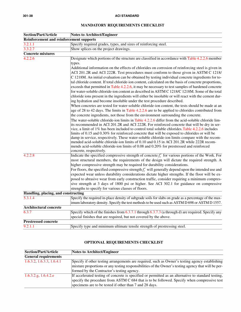
301-38 ACI STANDARD
MANDATORY REQUIREMENTS CHECKLIST
Section/Part/Article Notes to Architect/EngineerReinforcement and reinforcement supports3.2.1.1 Specify required grades, types, and sizes of reinforcing steel.3.3.2.7 Show splices on the project drawings.Concrete mixtures4.2.2.6 Designate which portions of the structure are classified in accordance with Table 4.2.2.6 member
types.Additional information on the effects of chlorides on corrosion of reinforcing steel is given inACI 201.2R and ACI 222R. Test procedures must conform to those given in ASTM C 1218/C 1218M. An initial evaluation can be obtained by testing individual concrete ingredients for to-tal chloride content. If total chloride-ion content, calculated on the basis of concrete proportions,exceeds that permitted in Table 4.2.2.6, it may be necessary to test samples of hardened concretefor water-soluble chloride-ion content as described in ASTM C 1218/C 1218M. Some of the totalchloride ions present in the ingredients will either be insoluble or will react with the cement dur-ing hydration and become insoluble under the test procedure described.When concretes are tested for water-soluble chloride-ion content, the tests should be made at anage of 28 to 42 days. The limits in Table 4.2.2.6 are to be applied to chlorides contributed fromthe concrete ingredients, not those from the environment surrounding the concrete.The water-soluble chloride-ion limits in Table 4.2.2.6 differ from the acid-soluble chloride lim-its recommended in ACI 201.2R and ACI 222R. For reinforced concrete that will be dry in ser-vice, a limit of 1% has been included to control total soluble chlorides. Table 4.2.2.6 includes limits of 0.15 and 0.30% for reinforced concrete that will be exposed to chlorides or will be damp in service, respectively. These water-soluble chloride-ion limits compare with the recom-mended acid-soluble chloride-ion limits of 0.10 and 0.15 in ACI 201.2R while 222R recom-mends acid-soluble chloride-ion limits of 0.08 and 0.20% for prestressed and reinforced concrete, respectively.
4.2.2.8 Indicate the specified compressive strength of concrete fc′ for various portions of the Work. Formost structural members, the requirements of the design will dictate the required strength. Ahigher compressive strength may be required for durability considerations.For floors, the specified compressive strength fc′ will generally depend upon the intended use andexpected wear unless durability considerations dictate higher strengths. If the floor will be ex-posed to abrasive wear from early construction traffic, consider requiring a minimum compres-sive strength at 3 days of 1800 psi or higher. See ACI 302.1 for guidance on compressivestrengths to specify for various classes of floors.
Handling, placing, and constructing5.3.1.4 Specify the required in-place density of subgrade soils for slabs on grade as a percentage of the max-
imum laboratory density. Specify the test methods to be used such as ASTM D 698 or ASTM D 1557.Architectural concrete6.3.7 Specify which of the finishes from 6.3.7.1 through 6.3.7.3 (a through d) are required. Specify any
special finishes that are required, but not covered by the above.Prestressed concrete9.2.1.1 Specify type and minimum ultimate tensile strength of prestressing steel.
OPTIONAL REQUIREMENTS CHECKLIST
Section/Part/Article Notes to Architect/EngineerGeneral requirements1.6.3.2, 1.6.3.3, 1.6.4.1 Specify if other testing arrangements are required, such as Owner’s testing agency establishing
mixture proportions or any testing responsibilities of the Owner’s testing agency that will be per-formed by the Contractor’s testing agency.
1.6.3.2.g, 1.6.4.2.e If accelerated testing of concrete is specified or permitted as an alternative to standard testing,specify the procedure from ASTM C 684 that is to be followed. Specify when compressive testspecimens are to be tested if other than 7 and 28 days.

301-39SPECIFICATIONS FOR STRUCTURAL CONCRETE
OPTIONAL REQUIREMENTS CHECKLIST, continued
Section/Part/Article Notes to Architect/Engineer1.6.4.3 Specify additional testing services desired for the work, if applicable. Note that these additional
testing services are to be performed by the Owner’s testing laboratory; hence, the term “will” isused in place of “shall” in 1.6.4.3. Refer to ACI 311.1R (SP-2), ACI 311.4R, and 311.5R for spe-cific inspection items that may be appropriate.When it is necessary or desirable to know properties of concrete at the point of placement or at lo-cations other than the delivery point, specify that concrete is to be sampled at these other locationsfor testing. See the discussion under Optional Requirements in Section 4.2.2.2.
1.6.5.2 Specify if nondestructive tests will be permitted to evaluate uniformity or relative in-placestrength of concrete. Refer to ACI 228.1R for guidance on nondestructive test methods.
1.6.7.1 If another basis for acceptance of concrete strength level is required for accelerated strength test-ing, specify the basis for acceptance.
Formwork and formwork accessories2.1.2.1 Review the list of submittal items and specify in Contract Documents the items not to be submitted.2.1.2.2 Review the list of submittal items and specify in Contract Documents the items to be submitted.2.2.1.2 Indicate where walls require form ties with water-barrier plates.2.2.2.1 Specify if calculations and drawings for formwork must be sealed by a licensed Engineer.2.2.2.3 Specify if earth cuts will be permitted or required.2.2.2.4 Specify more or less stringent limitations on deflection of facing materials when needed. See
ACI 347R for further guidance.2.2.2.5.b Specify or allow alternative locations for formed construction joints when necessary to facilitate
formwork removal or accelerate construction, provided that the alternative joint locations do not affect adversely the strength of the structure.
2.2.3.2 Specify if chamfer strips are not required on exterior corners of permanently exposed surfaces. Spec-ify if bevels are required on re-entrant corners of concrete or on edges of formed concrete joints.
2.3.1.2 Specify tolerance limits required to be different than those of ACI 117. Specify when a more orless restrictive tolerance for abrupt offset is required. Refer to ACI 347R and the Commentary toACI 117 for further guidance.
2.3.2.5 Specify the minimum compressive strength for removal of forms supporting the weight of con-crete if different than the specified compressive strength of concrete. Specify if nonload-carryingform-facing material is not permitted to be removed at an earlier age than the load-carrying por-tion of the formwork.
2.3.4.2 Specify if the alternative methods for evaluating concrete strength for formwork removal are permitted.Reinforcement and reinforcement supports3.1.1 Specify if the submittals listed in 3.1.1.1 through 3.1.1.3 are not required to be submitted. Other-
wise, they will be required to be submitted.3.2.1.1 For forged heads, specify type of steel for reinforcing bars:
• Low alloy steel (ASTM A 706/A 706M)• Billet steel (ASTM A 615/A 615M). For billet steel (ASTM A 615/A 615M) also specify
grade• Rail steel or axle steel deformed bars (ASTM A 996/A 996M).
3.2.1.2 Specify if coated reinforcing bars are required and, if so, whether the coating is to be zinc or epoxy.3.2.1.2.a For zinc-coated reinforcing bars conforming to ASTM A 767/A 767M, specify the class of coating,
whether galvanization is to be performed before or after fabrication, and indicate which bars requirespecial finished bend diameters (usually smaller sizes used for stirrup and ties).Avoid mixing galvanized and nongalvanized reinforcing steel or other embedded steel that couldresult in galvanic cells.
3.2.1.2.b Specify the ASTM specification to which epoxy-coated reinforcing bars are to conform.3.2.1.4 Specify which of the three combinations will apply.3.2.1.5 Specify plain or deformed wire and, if required, epoxy-coated wire.3.2.1.6 Specify plain or deformed wire fabric and, if required, epoxy-coated wire fabric. Refer to WRI
Manual of Standard Practice for additional guidance.3.2.1.7 Specify if wire-reinforcement supports other than those in 3.2.1.6 are required or permitted.
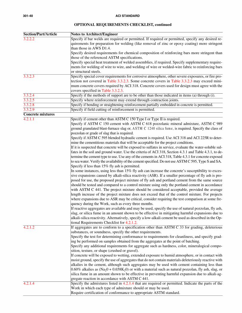
301-40 ACI STANDARD
OPTIONAL REQUIREMENTS CHECKLIST, continued
Section/Part/Article Notes to Architect/Engineer3.2.2.2 Specify if bar welds are required or permitted. If required or permitted, specify any desired re-
quirements for preparation for welding (like removal of zinc or epoxy coating) more stringentthan those in AWS D1.4.Specify desired requirements for chemical composition of reinforcing bars more stringent thanthose of the referenced ASTM specifications.Specify special heat treatment of welded assemblies, if required. Specify supplementary require-ments for welding of wire to wire, and welding of wire or welded-wire fabric to reinforcing barsor structural steels.
3.3.2.3 Specify special cover requirements for corrosive atmosphere, other severe exposures, or fire pro-tection not covered in Table 3.3.2.3. Some concrete covers in Table 3.3.2.3 may exceed mini-mum concrete covers required by ACI 318. Concrete covers used for design must agree with thecovers specified in Table 3.3.2.3.
3.3.2.4 Specify if the methods of support are to be other than those indicated in items (a) through (i).3.3.2.5 Specify where reinforcement may extend through contraction joints.3.3.2.8 Specify if bending or straightening reinforcement partially embedded in concrete is permitted.3.3.2.9 Specify if field cutting of reinforcement is permitted.Concrete mixtures4.2.1.1 Specify if cement other than ASTM C 150 Type I or Type II is required.
Specify if ASTM C 150 cement with ASTM C 618 pozzolanic mineral admixture, ASTM C 989ground granulated blast-furnace slag or, A S T M C 1240 silica fum e, is required. Specify the class ofpozzolan or grade of slag that is required. Specify if ASTM C 595 blended hydraulic cement is required. Use ACI 318 and ACI 225R to deter-mine the cementitious materials that will be acceptable for the project conditions.If it is suspected that concrete will be exposed to sulfates in service, evaluate the water-soluble sul-fates in the soil and ground water. Use the criteria of ACI 318, Section 4.3.1 and Table 4.3.1, to de-termine the cement type to use. Use any of the cements in ACI 318, Table 4.3.1 for concrete exposedto sea water. Verify the availability of the cement specified. Do not use ASTM C 595, Type S and SA. Specify if less than 15% fly ash is permitted. In some instances, using less than 15% fly ash can increase the concrete’s susceptibility to exces-sive expansions caused by alkali-silica reactivity (ASR). If a smaller percentage of fly ash is pro-posed for use, the proposed project mixture of fly ash and portland cement from the same sourceshould be tested and compared to a control mixture using only the portland cement in accordancewith ASTM C 441. The project mixture should be considered acceptable, provided the averagelength increase of the project mixture does not exceed that of the control mixture. For projectswhere expansions due to ASR may be critical, consider requiring the test comparison at some fre-quency during the Work, such as every three months. If reactive aggregates are available and may be used, specify the use of natural pozzolan, fly ash,slag, or silica fume in an amount shown to be effective in mitigating harmful expansions due toalkali-silica reactivity. Alternatively, specify a low-alkali cement be used as described in the Op-tional Requirements Checklist for 4.2.1.2.
4.2.1.2 If aggregates are to conform to a specification other than ASTM C 33 for grading, deleterioussubstances, or soundness, specify the other requirements.Specify the test for determining conformance to requirements for cleanliness, and specify grad-ing be performed on samples obtained from the aggregates at the point of batching.Specify any additional requirements for aggregate such as hardness, color, mineralogical compo-sition, texture, or shape (crushed or gravel).If concrete will be exposed to wetting, extended exposure to humid atmosphere, or in contact withmoist ground, specify the use of aggregates that do not contain materials deleteriously reactive withalkalies in the cement, although such aggregates may be used with cement containing less than0.60% alkalies as (Na20 + 0.658K20) or with a material such as natural pozzolan, fly ash, slag, orsilica fume in an amount shown to be effective in preventing harmful expansion due to alkali-ag-gregate reaction in accordance with ASTM C 441.
4.2.1.4 Specify the admixtures listed in 4.2.1.4 that are required or permitted. Indicate the parts of theWork in which each type of admixture should or may be used.Require certification of conformance to appropriate ASTM standard.
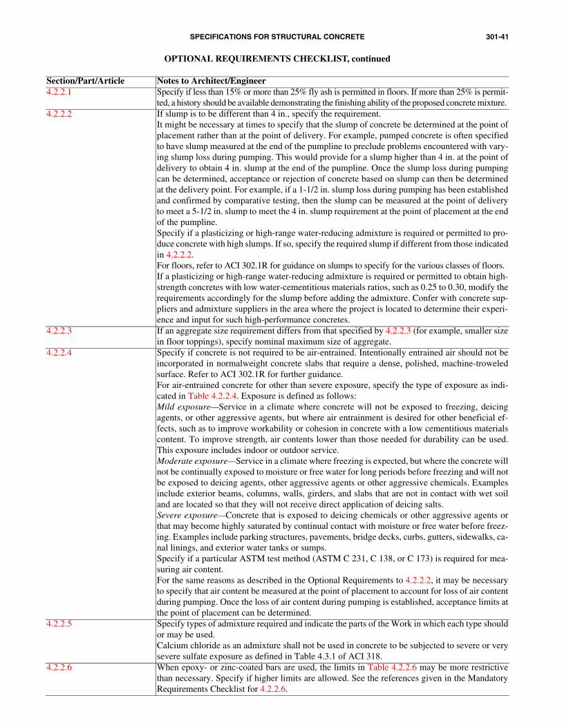
301-41SPECIFICATIONS FOR STRUCTURAL CONCRETE
OPTIONAL REQUIREMENTS CHECKLIST, continued
Section/Part/Article Notes to Architect/Engineer4.2.2.1 Specify if less than 15% or more than 25% fly ash is permitted in floors. If more than 25% is permit-
ted, a history should be available demonstrating the finishing ability of the proposed concrete mixture. 4.2.2.2 If slump is to be different than 4 in., specify the requirement.
It might be necessary at times to specify that the slump of concrete be determined at the point ofplacement rather than at the point of delivery. For example, pumped concrete is often specifiedto have slump measured at the end of the pumpline to preclude problems encountered with vary-ing slump loss during pumping. This would provide for a slump higher than 4 in. at the point ofdelivery to obtain 4 in. slump at the end of the pumpline. Once the slump loss during pumpingcan be determined, acceptance or rejection of concrete based on slump can then be determinedat the delivery point. For example, if a 1-1/2 in. slump loss during pumping has been establishedand confirmed by comparative testing, then the slump can be measured at the point of deliveryto meet a 5-1/2 in. slump to meet the 4 in. slump requirement at the point of placement at the endof the pumpline. Specify if a plasticizing or high-range water-reducing admixture is required or permitted to pro-duce concrete with high slumps. If so, specify the required slump if different from those indicatedin 4.2.2.2.For floors, refer to ACI 302.1R for guidance on slumps to specify for the various classes of floors.If a plasticizing or high-range water-reducing admixture is required or permitted to obtain high-strength concretes with low water-cementitious materials ratios, such as 0.25 to 0.30, modify therequirements accordingly for the slump before adding the admixture. Confer with concrete sup-pliers and admixture suppliers in the area where the project is located to determine their experi-ence and input for such high-performance concretes.
4.2.2.3 If an aggregate size requirement differs from that specified by 4.2.2.3 (for example, smaller sizein floor toppings), specify nominal maximum size of aggregate.
4.2.2.4 Specify if concrete is not required to be air-entrained. Intentionally entrained air should not beincorporated in normalweight concrete slabs that require a dense, polished, machine-troweledsurface. Refer to ACI 302.1R for further guidance. For air-entrained concrete for other than severe exposure, specify the type of exposure as indi-cated in Table 4.2.2.4. Exposure is defined as follows:Mild exposure—Service in a climate where concrete will not be exposed to freezing, deicingagents, or other aggressive agents, but where air entrainment is desired for other beneficial ef-fects, such as to improve workability or cohesion in concrete with a low cementitious materialscontent. To improve strength, air contents lower than those needed for durability can be used.This exposure includes indoor or outdoor service.Moderate exposure—Service in a climate where freezing is expected, but where the concrete willnot be continually exposed to moisture or free water for long periods before freezing and will notbe exposed to deicing agents, other aggressive agents or other aggressive chemicals. Examplesinclude exterior beams, columns, walls, girders, and slabs that are not in contact with wet soiland are located so that they will not receive direct application of deicing salts.Severe exposure—Concrete that is exposed to deicing chemicals or other aggressive agents orthat may become highly saturated by continual contact with moisture or free water before freez-ing. Examples include parking structures, pavements, bridge decks, curbs, gutters, sidewalks, ca-nal linings, and exterior water tanks or sumps.Specify if a particular ASTM test method (ASTM C 231, C 138, or C 173) is required for mea-suring air content.For the same reasons as described in the Optional Requirements to 4.2.2.2, it may be necessaryto specify that air content be measured at the point of placement to account for loss of air contentduring pumping. Once the loss of air content during pumping is established, acceptance limits atthe point of placement can be determined.
4.2.2.5 Specify types of admixture required and indicate the parts of the Work in which each type shouldor may be used.Calcium chloride as an admixture shall not be used in concrete to be subjected to severe or verysevere sulfate exposure as defined in Table 4.3.1 of ACI 318.
4.2.2.6 When epoxy- or zinc-coated bars are used, the limits in Table 4.2.2.6 may be more restrictivethan necessary. Specify if higher limits are allowed. See the references given in the MandatoryRequirements Checklist for 4.2.2.6.
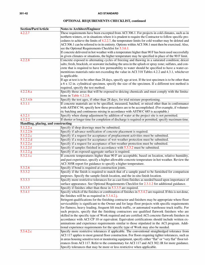
301-42 ACI STANDARD
OPTIONAL REQUIREMENTS CHECKLIST, continued
Section/Part/Article Notes to Architect/Engineer4.2.2.7 These requirements have been excerpted from ACI 306.1. For projects in cold climates, such as in
northern winters, or in situations where it is prudent to require the Contractor to follow specific pro-cedures to achieve the limits of 4.2.2.7, the temperature limits for cold weather may be deleted andACI 306.1 can be referred to in its entirety. Options within ACI 306.1 must then be exercised. Also,see the Optional Requirements Checklist for 5.3.6.1. If concrete delivered in hot weather with a temperature higher than 90 F has been used successfullyin given climates or situations, the higher temperature may be specified in place of the 90 F limit.
4.2.2.8 Concrete exposed to alternating cycles of freezing and thawing in a saturated condition; deicersalts; fresh, brackish, or seawater including the area in the splash or spray zone; sulfates, and con-crete that is required to have low permeability to water should be specified to have a water-ce-mentitious materials ratio not exceeding the value in ACI 318 Tables 4.2.2 and 4.3.1, whicheveris applicable.If age at test is to be other than 28 days, specify age at test. If the test specimen is to be other thana 6 x 12 in. cylindrical specimen, specify the size of the specimen. If a different test method isrequired, specify the test method.
4.2.2.8.a Specify those areas that will be exposed to deicing chemicals and must comply with the limita-tions in Table 4.2.2.8.
4.2.3.4.b Specify the test ages, if other than 28 days, for trial mixture proportioning.4.3.1.1 If concrete materials are to be specified, measured, batched, or mixed other than in conformance
with ASTM C 94, specify how these procedures are to be accomplished. (For example, if volumet-ric batching and continuous mixing in accordance with ASTM C 685 is acceptable.)
4.3.2.1 Specify when slump adjustment by addition of water at the project site is not permitted.4.3.2.2 If shorter or longer time for completion of discharge is required or permitted, specify maximum time.Handling, placing, and constructing5.1.2.2.a Specify if shop drawings must be submitted.5.1.2.2.b Specify if advance notification of concrete placement is required.5.1.2.2.c Specify if a request for acceptance of preplacement activities must be submitted.5.1.2.2.d Specify if a request for acceptance of wet-weather protection must be submitted.5.1.2.2.e Specify if a request for acceptance of hot-weather protection must be submitted.5.1.2.2.f Specify if samples finished in accordance with 5.3.3.2 must be submitted.5.1.2.2.g Specify if an exposed-aggregate surface is required.5.3.2.1.c If concrete temperatures higher than 90 F are acceptable, based on location, relative humidity,
and past experience, specify a higher allowable concrete temperature in hot weather. Review theACI 305R report for guidance to specify a higher temperature.
5.3.2.6 Specify if bond is required at construction joints.5.3.3.2 Specify if the finish is required to match that of a sample panel to be furnished for comparison
purposes. Specify the sample finish location, and the in-situ finish location.5.3.3.3 Specify more restrictive tolerances for as-cast form finishes as needed based upon importance of
surface appearance. See Optional Requirements Checklist for 2.3.1.2 for additional guidance. 5.3.3.5 Specify if finishes other than those in 5.3.3.5 are required.5.3.4.1 Specify which of the finishes or combination of finishes in 5.3.4.2 are required. If this is not done,
the finishes will be as required in 5.3.4.2.j.Stringent qualifications for the finishing contractor and finishers may be appropriate where floorserviceability is significant to the Owner and for large floor projects with specific requirementsfor flatness, heavy loading, frequent lift truck traffic, or automated warehouse truck traffic. Forsuch projects, specify that the finishing contractors use qualified flatwork finishers who areskilled in the specific type of Work required and are certified ACI concrete flatwork finishers inaccordance with ACI CP 10 or equivalent. Equivalent certifications should include written ex-aminations and experience requirements similar to those stipulated in the ACI program. Addi-tional experience requirements for the specific type of Work may also be needed.
5.3.4.2.c Specify more restrictive tolerances if applicable. The conventional straightedged tolerance fromACI 117 applies to most general floor construction. For floors requiring tighter tolerances, such asin areas housing sensitive test or monitoring equipment, specify either “flat” or “very flat” floor tol-erances from ACI 117. Refer to the commentary for ACI 117 and ACI 302.1R for more guidance.Specify tolerances that may be more or less restrictive when applicable.

301-43SPECIFICATIONS FOR STRUCTURAL CONCRETE
OPTIONAL REQUIREMENTS CHECKLIST, continued
Section/Part/Article Notes to Architect/Engineer5.3.4.2.e For dry-shake finishes, specify the metallic or mineral aggregate, the final finishing method, and
the location.5.3.4.2.f For heavy-duty topping for two-course slabs, specify the materials, the final finishing method,
and the location.5.3.4.2.h For nonslip finishes, specify the location. Where abrasive particles other than crushed aluminum
oxides are to be used, specify the other abrasive particles.5.3.4.2.i For exposed-aggregate finishes, specify the location, color, and size of aggregate. (Usually 3/8
to 5/8 in.)5.3.4.3.b, 5.3.4.3.c Alternative tolerance test methods, types of floors, and floor areas may be specified where appli-
cable. The 10 ft straightedge method of measuring tolerances from ACI 117 applies to manysmall general floor construction applications. The ACI 117 F-number measuring system appliesto many large specialized and general floor construction applications. For floors requiring tightertolerances, such as in areas with frequent lift-truck traffic, automated warehouse forklifts, orhousing sensitive test and monitoring equipment, specify either “flat” or “very flat” floor toler-ances from ACI 117 using the F-number measuring system. When specifying the F-number mea-suring system for unshored floors, specify only the FF value, not the FL value. Note that thecommentary for ACI 117 contains cautions (per ASTM E 1155) to not use the F-number mea-suring system within 2 ft of an imbed or construction joint. Caution should also be used in spec-ifying the F-number measuring system in floor areas that slope, unless a specific constant slopehas been specified so that the FF value is appropriate. Refer to the commentary for ACI 117 andACI 302.1R for further guidance.
5.3.5 Specify if saw-cut contraction joints are required.5.3.6.1 For concrete surfaces that require enhanced durability, such as high wear resistance, low perme-
ability, or minimal cracking, a longer duration of curing may be needed than is required to meetcompressive strength criteria alone. When such enhanced properties are required, minimum cur-ing periods of 7 days for high-early-strength concrete, 14 days for concrete incorporating TypeI or Type II cements, and 14 to 21 days for concrete incorporating pozzolan as one of the cemen-titious materials are recommended. See ACI 308 for additional guidance.Specify if a curing procedure of 5.3.6.4 that supplies additional water is required.
5.3.6.5 Requirements for rate of temperature change have been excerpted from ACI 306.1. For optionalcold-weather concreting requirements, see the Optional Requirements Checklist for 4.2.2.7 andspecify ACI 306.1 in its entirety, if appropriate.
5.3.7.7 If stains, rust, efflorescence, and surface deposits are to be prohibited, describe the degree towhich they are unacceptable.
Architectural concrete6.1.1.1 Designate areas to be treated as architectural concrete. Describe special color requirements. If
necessary, specify a symmetrical array of formwork panels of a specified size.6.1.1.3 Review Sections 1 through 5 and specify requirements to be omitted or added for architectural
concrete.Designate any special cementitious materials, aggregates, or admixtures required for architectur-al concrete.
6.1.3.1 If the importance of the Work warrants it, list operations for which a technical specialist, trainedor approved by the specialty item manufacturer, is to be on the project site to provide technical as-sistance during the first three days of construction operations using the specialty item. Specify anyother times when a technical specialist is to be on the project site to provide technical assistance.
6.1.3.3 Specify for which structural items the Contractor is to make full-scale mock-ups as samples offinished construction.
6.2.2.1.d Specify if it is permissible for ties to be located within exposed areas of architectural concrete.6.3.2, 6.3.7.4 Specify areas where designated colors and uniformity of color need not be maintained. Specify
areas where stucco, or cementitious coating is required. If so, specify applicable requirements orrefer to the applicable part of the Contract Documents for such requirements. If applicable, spec-ify required color.
6.3.3 Specify areas where a smooth-rubbed or similar finish is required.6.3.6.1 Specify areas where as-cast finishes are permitted or required.
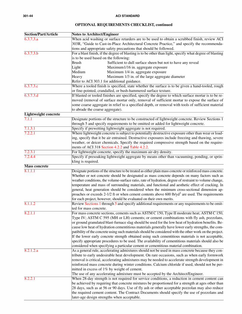
301-44 ACI STANDARD
OPTIONAL REQUIREMENTS CHECKLIST, continued
Section/Part/Article Notes to Architect/Engineer6.3.7.3.a When acid washing or surface retarders are to be used to obtain a scrubbed finish, review ACI
303R, “Guide to Cast-in-Place Architectural Concrete Practice,” and specify the recommenda-tions and appropriate safety precautions that should be followed.
6.3.7.3.b For a blast finish, if the degree of blasting is to be other than light, specify what degree of blastingis to be used based on the following:Brush Sufficient to dull surface sheen but not to have any revealLight Maximum1/16 in. aggregate exposureMedium Maximum 1/4 in. aggregate exposureHeavy Maximum 1/3 in. of the large aggregate diameterRefer to ACI 303.1 for additional guidance.
6.3.7.3.c Where a tooled finish is specified, state whether the surface is to be given a hand-tooled, roughor fine-pointed, crandalled, or bush-hammered surface texture.
6.3.7.3.d If blasted or tooled finishes are specified, specify the degree to which surface mortar is to be re-moved (removal of surface mortar only, removal of sufficient mortar to expose the surface ofsome coarse aggregate in relief to a specified depth, or removal with tools of sufficient materialto abrade the coarse aggregate).
Lightweight concrete7.1.1 Designate portions of the structure to be constructed of lightweight concrete. Review Sections 1
through 5 and specify requirements to be omitted or added for lightweight concrete.7.1.3.1 Specify if prewetting lightweight aggregate is not required.7.2.2.1 Where lightweight concrete is subject to potentially destructive exposure other than wear or load-
ing, specify that it be air entrained. Destructive exposures include freezing and thawing, severeweather, or deicer chemicals. Specify the required compressive strength based on the require-ments of ACI 318 Section 4.2.2 and Table 4.2.2.
7.2.3.1 For lightweight concrete, specify the maximum air-dry density.7.2.4.4 Specify if presoaking lightweight aggregate by means other than vacuuming, ponding, or sprin-
kling is required.Mass concrete8.1.1.1 Designate portions of the structure to be treated as either plain mass concrete or reinforced mass concrete.
Whether or not concrete should be designated as mass concrete depends on many factors such asweather conditions, the volume-surface ratio, rate of hydration, degree of restraint to volume change,temperature and mass of surrounding materials, and functional and aesthetic effect of cracking. Ingeneral, heat generation should be considered when the minimum cross-sectional dimension ap-proaches or exceeds 2-1/2 ft or when cement contents above 600 lb/yd3 are used. The requirementsfor each project, however, should be evaluated on their own merits.
8.1.1.2 Review Sections 1 through 5 and specify additional requirements or any requirements to be omit-ted for mass concrete.
8.2.1.1 For mass concrete sections, cements such as ASTM C 150, Type II moderate heat; ASTM C 150,Type IV; ASTM C 595 (MH or LH) cements; or cement combinations with fly ash, pozzolans,or ground granulated blast-furnace slag should be used for the low heat of hydration benefits. Be-cause low heat of hydration cementitious materials generally have lower early strengths, the com-patibility of the concrete using such materials should be considered with the other work on the project.If the lower early concrete strength obtained using such cementitious materials is not acceptable,specify appropriate procedures to be used. The availability of cementitious materials should also beconsidered when specifying a particular cement or cementitious material combination.
8.2.1.2.a As a general rule, accelerating admixtures should not be used in mass concrete because they con-tribute to early undesirable heat development. On rare occasions, such as when early formworkremoval is critical, accelerating admixtures may be needed to accelerate strength development inreinforced mass concrete during winter conditions. Calcium chloride if used, should not be per-mitted in excess of 1% by weight of cement.The use of any accelerating admixture must be accepted by the Architect/Engineer.
8.2.2.1 When 28-day strength is not required for service conditions, a reduction in cement content canbe achieved by requiring that concrete mixtures be proportioned for a strength at ages other than28 days, such as at 56 or 90 days. Use of fly ash or other acceptable pozzolan may also reducethe required cement content. The Contract Documents should specify the use of pozzolans andlater-age design strengths when acceptable.

301-45SPECIFICATIONS FOR STRUCTURAL CONCRETE
OPTIONAL REQUIREMENTS CHECKLIST, continued
Section/Part/Article Notes to Architect/Engineer8.2.2.2 Specify the maximum permissible slump if it is to be other than 3 in. for plain mass concrete or
that required by 4.2.2.2 for reinforced mass concrete.8.3.1.1 If the limits on temperature of concrete when deposited are to be other than as given in 8.3.1.1,
specify maximum and minimum placing temperatures.8.3.2.1.a A curing period of 7 days is sufficient for mass concrete proportioned for a 28-day specified
strength. When concrete strength is based upon 56 or 90 day compressive strength, the curingperiod should be extended to a minimum of 14 days. Specify the duration of curing if longer than7 days is required.
8.3.2.1.b Mass concrete is best cured with water for the additional cooling benefit in warm weather. Whenwater curing is impractical, such as when the surrounding air temperature is less than 32 F, othermethods such as the use of liquid membrane-forming compounds may be used. Specify if a par-ticular curing method is desired.
8.3.2.4 Specify additional or optional temperature controls as appropriate to minimize thermal cracking.For example, limitations on temperature differentials between the center and surface of the con-crete may be desirable for large structurally reinforced placements such as large mat foundationsif the entire concrete section can be cast in one continuous placement and the external restraintfrom adjacent concrete elements can be avoided. Complying with limitations on temperature dif-ferentials will normally require keeping concrete warm with insulation. Additional reinforcingsteel may also be needed to minimize crack widths from base restraint and the higher peak con-crete temperatures. See PCA publication “Design and Control of Concrete Mixtures,” 13th edi-tion, and ACI 207.2R for additional guidance.
Prestressed concrete9.1.1 Review Section 1 through 5 and specify additional requirements or requirements to be omitted
for prestressed concrete.9.1.2.2 If required, specify that the Contractor submit test data substantiating expected coefficients and
anchorage set.9.1.3.1.c Specify if a cyclic test of unbonded tendons is required.9.2.1.4.b Indicate areas that are considered to be corrosive environments where encapsulation of the pre-
stressing steel at stressing, intermediate, and fixed anchorages is required.9.2.1.6 Specify if unbonded tendon anchorages are permitted.9.2.1.7 Indicate areas where couplings may be used.9.3.2.2.d Indicate areas that will be exposed to an atmosphere of salt air or high humidity.9.3.4.1 Specify the sequence, the concrete strength, and the stages at which tendons should be stressed.Shrinkage-compensating concrete10.2.1.1.a If an expansive cement other than ASTM C 845, Type E-1 (K) is acceptable or required, specify
the cement type.10.2.1.1.c Fly ash or ground granulated blast-furnace slag will affect the expansion and should not be used
without adequate testing.10.2.1.2.a Accelerating admixtures, specifically ones that contain calcium chloride, may reduce the expan-
sion of the concrete and should not be permitted for use in shrinkage-compensating concrete.10.2.1.2.b Admixtures may have an effect on the expansion of the specific concrete mixture. Do not permit
changes in admixture dosage or type without additional testing. See ACI 223 for additional information.10.2.2.2 If different minimum and maximum limits for expansion are desired, specify the requirements.
Minimum expansion needed is based on the projected shrinkage for the particular concrete mix-ture and the amount of reinforcement used. Consult ACI 223 for guidance.
10.2.2.3 If slump is to be different than 6 in. maximum at the point of placement, specify the requirement.Refer to Optional Requirements Checklist 4.2.2.2 for guidance on slump loss between deliveryand placements points.
10.2.3.1 Due to the initial slump loss of shrinkage-compensating concrete, it is necessary to proportionthe concrete mixture to consider initial slump loss. If the concrete mixture used in the Work has a delivery time longer than 20 min, specify a longerhold time to be used in the trial mixture proportioning procedure. Consult ACI 223 for guidance.
10.2.4 Specify the grade of reinforcing bar and the amounts of reinforcement required.Shrinkage-compensating concrete must always be reinforced. The reinforcement should be de-termined in accordance with ACI 318. See ACI 223 for additional guidance.
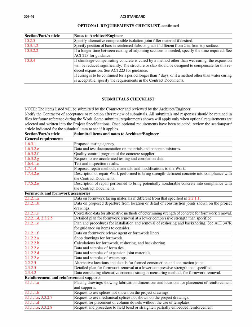
301-46 ACI STANDARD
OPTIONAL REQUIREMENTS CHECKLIST, continued
Section/Part/Article Notes to Architect/Engineer10.2.5 Specify alternative compressible isolation-joint filler material if desired.10.3.1.2 Specify position of bars in reinforced slabs on grade if different from 2 in. from top surface.10.3.2.2 If a longer time between casting of adjoining sections is needed, specify the time required. See
ACI 223 for guidance.10.3.4 If shrinkage-compensating concrete is cured by a method other than wet curing, the expansion
will be reduced significantly. The structure or slab should be designed to compensate for this re-duced expansion. See ACI 223 for guidance.If curing is to be continued for a period longer than 7 days, or if a method other than water curingis acceptable, specify the requirements in the Contract Documents.
SUBMITTALS CHECKLIST
NOTE: The items listed will be submitted by the Contractor and reviewed by the Architect/Engineer.Notify the Contractor of acceptance or rejection after review of submittals. All submittals and responses should be retained infiles for future reference during the Work. Some submittal requirements shown will apply only when optional requirements areselected and written into the Project Specifications. Once optional requirements have been selected, review the section/part/article indicated for the submittal item to see if it applies. Section/Part/Article Submittal items and notes to Architect/EngineerGeneral requirements1.6.3.1 Proposed testing agency.1.6.3.2.e Data and test documentation on materials and concrete mixtures.1.6.3.2.f Quality-control program of the concrete supplier.1.6.3.2.g Request to use accelerated testing and correlation data.1.6.4.1.c Test and inspection results.1.7.1.4 Proposed repair methods, materials, and modifications to the Work.1.7.4.2.e Description of repair Work performed to bring strength-deficient concrete into compliance with
the Contract Documents.1.7.5.2.e Description of repair performed to bring potentially nondurable concrete into compliance with
the Contract Documents.Formwork and formwork accessories2.1.2.1.a Data on formwork facing materials if different from that specified in 2.2.1.1.2.1.2.1.b Data on proposed departure from location or detail of construction joints shown on the project
drawings. 2.1.2.1.c Correlation data for alternative methods of determining strength of concrete for formwork removal.2.2.2.1.d, 2.3.2.5 Detailed plan for formwork removal at a lower compressive strength than specified.2.1.2.1.e Plan and procedures for installation and removal of reshoring and backshoring. See ACI 347R
for guidance on items to consider.2.1.2.1.f Data on formwork release agent or formwork liners.2.1.2.2.a Shop drawings for formwork.2.1.2.2.b Calculations for formwork, reshoring, and backshoring.2.1.2.2.c Data and samples of form ties.2.1.2.2.d Data and samples of expansion joint materials.2.1.2.2.e Data and samples of waterstops.2.2.2.5 Alternative locations and details for formed construction and contraction joints.2.3.2.5 Detailed plan for formwork removal at a lower compressive strength than specified.2.3.4.2 Data correlating alternative concrete strength-measuring methods for formwork removal.Reinforcement and reinforcement supports3.1.1.1.a Placing drawings showing fabrication dimensions and locations for placement of reinforcement
and supports.3.1.1.1.b Request to use splices not shown on the project drawings.3.1.1.1.c, 3.3.2.7 Request to use mechanical splices not shown on the project drawings.3.1.1.1.d Request for placement of column dowels without the use of templates.3.1.1.1.e, 3.3.2.8 Request and procedure to field bend or straighten partially embedded reinforcement.

301-47SPECIFICATIONS FOR STRUCTURAL CONCRETE
SUBMITTALS CHECKLIST
Section/Part/Article Submittal items and notes to Architect/Engineer3.1.1.2.a Description of reinforcement weld locations, weld procedures, and welder qualifications.3.1.1.2.b Proposed supports for coated reinforcement and uncoated reinforcement not covered in 3.3.2.4.3.1.1.3.a, 3.3.2.2 When the Contractor finds it necessary to move reinforcement beyond the specified placing tol-
erances to avoid interference with other reinforcement, conduits, or embedded items, review asubmittal showing the resulting arrangement of reinforcement.
3.2.2.1 Request to heat and bend reinforcement.3.3.2.5 Request to extend welded wire fabric through contraction joints.3.3.2.9 Request to field cut reinforcement.Concrete mixtures4.1.2.1 Mixture proportions and characteristics. Check that mixture proportions conform to the require-
ments of 4.2.2 for cementitious-material content, yield, water-cementitious materials ratio,slump, nominal maximum size of coarse aggregate, air content, admixtures, and chloride-ionconcentration, as well as compressive strength.
4.1.2.2 Method and test data used to establish mixture proportions.Several different methods can be used to select mixture proportions to produce the necessaryplaceability, density, strength, and durability of the concrete.Field experience of concrete mixtures previously used under similar conditions provides the bestassurance that the proposed concrete mixture can be used satisfactorily and will have the speci-fied properties.If there is no field experience, ACI 211.1 provides guidance for selection of the initial quantitiesof materials based on material properties and specified concrete properties. When a field testrecord is not available, ACI 211.1 recommends that mixture characteristics be checked by trialbatches in the laboratory or in the field.Blending aggregates to meet criteria for a combined grading is another proportioning method thatcan be used. Listed below are some of the different procedures that have been used to determineproportions of blended aggregates:• Combined fineness modulus;• 8 to 18% retained on each of the standard sieves;• Coarseness factor chart;• 0.45 power chart.When one of the above or other similar methods are used, the specific combined grading to whichaggregate is to be blended, along with the tolerances for control, should be submitted. This meth-od also requires concrete characteristics to be checked by trial batches.
4.1.2.3 Information on types, classes, producers’ names, and plant locations for cementitious materials;types, pit or quarry locations, producers’ names, gradings and properties required by ASTM C33 for aggregates; types, brand names, and producers’ names for admixtures; and source of sup-ply for water and ice.Except for admixtures and water, test results confirming conformance with applicable specifica-tions shall not be more than 90 days old. Test results for aggregate soundness, abrasion, and re-activity may be older than 90 days, but not older than 1 year, provided test results for the otherproperties specified in ASTM C 33 indicate that the aggregate quality has not changed.
4.1.2.4 Materials, mixture proportions, and field strength-test data used for proportioning.4.1.2.5 Requests for adjustments to mixture proportions.
Requests to adjust mixture proportions necessary for workability or consistency.If the Contractor desires to decrease the cementitious-materials content of the concrete mixture af-ter having satisfied the requirements of 4.2.3.6, review a request for acceptance of the proposedrevised mixture with a lower cementitious-materials content on a trial basis.If the Contractor finds it necessary to increase the cementitious-materials content, review a re-quest for acceptance of the proposed revised mixture with a higher cementitious-materials con-tent on a trial basis.Confirmation that adequacy of modified proportions has been verified from a set of new field test data.
4.1.2.6 Evaluation and test results required in 4.2.2.1 verifying the adequacy of concrete to be placed infloors if the cement content is less than the minimum specified in Table 4.2.2.1.
4.1.2.7 Request to use calcium chloride.4.1.2.8 Request to use the volumetric batching method.

301-48 ACI STANDARD
SUBMITTALS CHECKLIST
Section/Part/Article Submittal items and notes to Architect/Engineer4.1.2.9 Requests to exceed the ASTM C 94 required time of discharge.4.2.1.1 Requests to use cementitious materials other than ASTM C 150 Type I or Type II.4.2.6.3.c Revised mixture proportions based on revised value of fcr′ .Handling, placing, and constructing5.1.2.1.a Test and inspection records.5.1.2.1.b Description of conveying equipment.5.1.2.1.c Proposed method of measuring concrete surface temperature changes.5.1.2.1.d Proposed repair method for removal of stains, rust, efflorescence, and surface deposits.5.1.2.1.e Qualifications of finishing contractor and flatwork finishers.5.1.2.2a Shop drawings of placing, handling, and constructing methods.5.1.2.2.b Advance notification of forthcoming placement. If required, arrange for tests and inspection to
be properly coordinated.5.1.2.2.c Request for acceptance of preplacement activities to ensure the preplacement activities are prop-
erly inspected, if necessary.5.1.2.2.d Proposed wet-weather protection activities.5.1.2.2.e Proposed precautions for placement of concrete hotter than 90 F.5.1.2.2.f Sample finish.5.1.2.2.g Specification and manufacturer’s data for chemical retarder used in producing exposed-aggre-
gate finish along with method of use.5.1.2.3.a Proposed location and treatment of construction joints not shown on the project drawings. Re-
view proposed methods for roughening the surface and the use of portland-cement grout.5.1.2.3.b Bonding agents other than cement grout for two-course slabs.5.1.2.3.c Proposed method for underwater placement.5.1.2.3.d Proposed location of contraction joints not indicated on the project drawings.5.1.2.3.e, 5.3.6.4 Proposed methods of curing other than those of 5.3.6.4.a through e.5.1.2.3.f Description of proposed coated form ties.5.1.2.3.g, 5.2.1.3, 5.3.7.6 Specification and data and methods of use for any proposed repair material other than site-mixed
portland-cement mortar described in 5.3.7.5 (see 5.3.7.6). For patches in exposed concrete, ex-ercise caution when using the materials described in 5.3.7.6, particularly with regard to both pos-sible color changes from weathering and delamination due to differing coefficients of thermalexpansion. Ensure that the material, including ASTM type or class, is appropriate for the mois-ture and thermal conditions of exposure.
5.3.2.1.c Request to exceed 90 F concrete temperature, along with proposed precautionary measures.5.3.2.6 Proposed materials and methods to prepare the concrete surface to achieve bond.5.3.4.2.f Request to use bonding agents other than cement grout.5.3.5 Detailed plan for alternate saw-cutting method, such as shallow-cut and dry-cut method. See ACI
302.1R for further guidance.5.3.6.5 Method of measuring concrete surface temperature.Architectural concrete6.1.2.1.a Shop drawings and fabricating drawings of formwork for architectural concrete. These drawings
should show jointing of facing panels; locations and details of form ties and recesses; details ofjoints, anchorages, and other accessories; and any necessary alignment bracing. Review drawingsfor condition of finished surface, jointing, location of form tie holes and their treatment, types ofform ties, location and details of rustication strips, leak-tightness, assembly, and removal.
6.1.2.2.a Request for the proposed location of full-scale mock-ups at the project site.6.1.2.2.b Mock-ups or sample panels of aggregate transfer and other special finishes.6.1.2.2.c When an exposed-aggregate finish is required, review a description of the method (such as blast-
ing, bush-hammering or use of a surface retarder) the Contractor desires to use to expose aggregate.Lightweight concrete7.1.2.1 Field placement test results.7.1.3.1 Request for alternate prewetting methods or times for lightweight aggregate.7.2.3.1 Data correlating air-dry density to fresh bulk density.
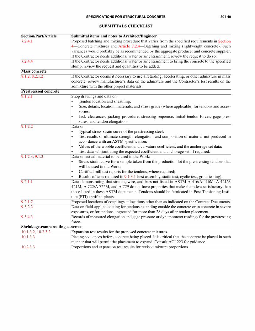
301-49SPECIFICATIONS FOR STRUCTURAL CONCRETE
SUBMITTALS CHECKLIST
Section/Part/Article Submittal items and notes to Architect/Engineer7.2.4.1 Proposed batching and mixing procedure that varies from the specified requirements in Section
4—Concrete mixtures and Article 7.2.4—Batching and mixing (lightweight concrete). Suchvariances would probably be as recommended by the aggregate producer and concrete supplier.If the Contractor needs additional water or air entrainment, review the request to do so.
7.2.4.4 If the Contractor needs additional water or air entrainment to bring the concrete to the specifiedslump, review the request and quantities to be added.
Mass concrete8.1.2, 8.2.1.2 If the Contractor deems it necessary to use a retarding, accelerating, or other admixture in mass
concrete, review manufacturer’s data on the admixture and the Contractor’s test results on theadmixture with the other project materials.
Prestresssed concrete9.1.2.1 Shop drawings and data on:
• Tendon location and sheathing;• Size, details, location, materials, and stress grade (where applicable) for tendons and acces-
sories;• Jack clearances, jacking procedure, stressing sequence, initial tendon forces, gage pres-
sures, and tendon elongation.9.1.2.2 Data on:
• Typical stress-strain curve of the prestressing steel;• Test results of ultimate strength, elongation, and composition of material not produced in
accordance with an ASTM specification;• Values of the wobble coefficient and curvature coefficient, and the anchorage set data;• Test data substantiating the expected coefficient and anchorage set, if required.
9.1.2.3, 9.1.3 Data on actual material to be used in the Work:• Stress-strain curve for a sample taken from the production lot the prestressing tendons that
will be used in the Work;• Certified mill test reports for the tendons, where required;• Results of tests required in 9.1.3.1 (test assembly, static test, cyclic test, grout testing).
9.2.1.1 Data demonstrating that strands, wire, and bars not listed in ASTM A 416/A 416M, A 421/A421M, A 722/A 722M, and A 779 do not have properties that make them less satisfactory thanthose listed in these ASTM documents. Tendons should be fabricated in Post Tensioning Insti-tute (PTI) certified plants.
9.2.1.7 Proposed locations of couplings at locations other than as indicated on the Contract Documents.9.3.2.2 Data on field-applied coating for tendons extending outside the concrete or in concrete in severe
exposures, or for tendons ungrouted for more than 28 days after tendon placement.9.3.4.3 Records of measured elongation and gage pressure or dynamometer readings for the prestressing
force.Shrinkage-compensating concrete10.1.3.2, 10.2.3.2 Expansion test results for the proposed concrete mixtures.10.1.3.3 Placing sequences before concrete being placed. It is critical that the concrete be placed in such
manner that will permit the placement to expand. Consult ACI 223 for guidance.10.2.3.3 Proportions and expansion test results for revised mixture proportions.