3001736 - efc21 - uk 20210715 - exodraftinfo.dk
TRANSCRIPT
UK
EFC21

2 • UK 3001736 - EFC21 - UK 20210715
1. Product information ......................................................................................................................31.1 Application .................................................................................................................................31.2 Description .................................................................................................................................4
2. Installation ........................................................................................................................................52.1 Fitting the controller ..................................................................................................................52.2 Electrical wiring ..........................................................................................................................52.3 EFC21 standard installation .......................................................................................................62.4 EFC21 installation with external ON/OFF ..................................................................................72.5 EFC21 coupled directly to a gas fireplace control .....................................................................8
3. Commissioning .................................................................................................................... 93.1 Service mode ............................................................................................................................103.2 Setting the potentiometer .......................................................................................................103.3 Setting the pressure switch ......................................................................................................103.4 Testing the commissioning set-up ...........................................................................................10
4. Daily use ..........................................................................................................................................114.1 Extra function ...........................................................................................................................12
5. Troubleshooting ...........................................................................................................................135.1 Start .........................................................................................................................................135.2 Operating ..................................................................................................................................13
6. Technical data ................................................................................................................................14
7. EU Declaration of Conformity ..................................................................................................15
Symbol Legend:
Prohibition symbol Failure to observe instructions marked with a prohibition symbol may result in serious injury or death.
Danger symbol Failure to observe instructions marked with a danger symbol may result in personal injury and/or damage to unit.
Area of application
This instruction is for the exodraft EFC21 chimney fan control system.
The instructions must be fully observed to ensure personal safety and to protect the equipment and ensure its correct operation.
exodraft a/s accepts no liability for accidents caused by equipment not used in accordance with the manual’s instructions and recommendations.
!
3001736 - EFC21 - UK 20210715 UK 3
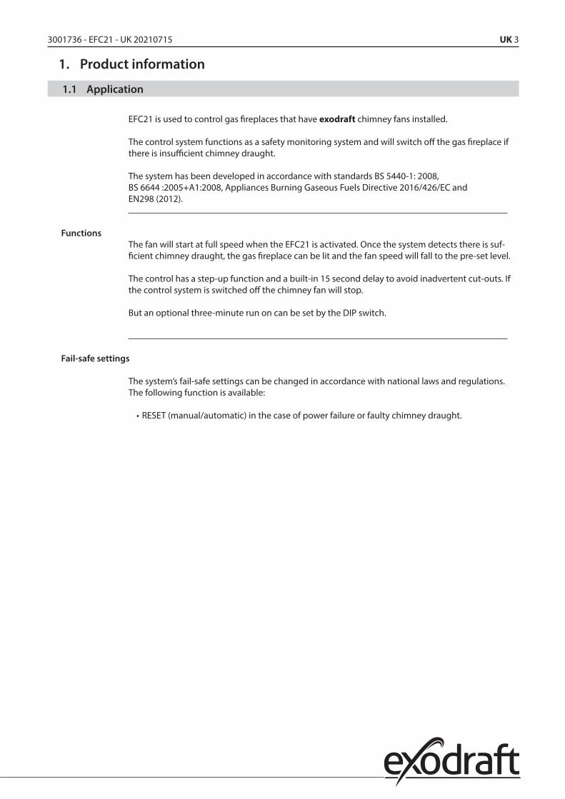
1. Product information
1.1 Application
EFC21 is used to control gas fireplaces that have exodraft chimney fans installed.
The control system functions as a safety monitoring system and will switch off the gas fireplace if there is insufficient chimney draught.
The system has been developed in accordance with standards BS 5440-1: 2008, BS 6644 :2005+A1:2008, Appliances Burning Gaseous Fuels Directive 2016/426/EC and EN298 (2012).
FunctionsThe fan will start at full speed when the EFC21 is activated. Once the system detects there is suf-ficient chimney draught, the gas fireplace can be lit and the fan speed will fall to the pre-set level.
The control has a step-up function and a built-in 15 second delay to avoid inadvertent cut-outs. If the control system is switched off the chimney fan will stop.
But an optional three-minute run on can be set by the DIP switch.
Fail-safe settings
The system’s fail-safe settings can be changed in accordance with national laws and regulations. The following function is available:
• RESET (manual/automatic) in the case of power failure or faulty chimney draught.

4 • UK 3001736 - EFC21 - UK 20210715
1.2 Description
Overview of EFC21 controller
SERVICEMODE
1 2
MAN
UAL
RES
ETPO
ST P
UR
GE
Umin+-
OFF
ON
4 51 2 3
12 138 9 10 11
LN
NregLINO NC C
FANOUT
PDSIN
+24V C NO
24V
+24V 24
V
INSTART AIR INLET
IN OUTRELEASE
230
VAC
SUPP
LY
R
5AT PULL
C D E F I J K
R Q P O
BA H
L
STEP 2OUT
NO
15
C
14
MNS
21 22 23
GR
EEN
BRO
WN
WH
ITE
RD
1128
1
Ext. IR-sensor
76
L N
OUTSMG
G
Ret også RD11472(anden positionering, til brochure)
Rev. 1 09-09-2010 Pil til nu fast monteret sikring er fjernet
Fig.1
Pos. Description Pos. Description
A Alarm LED K Potentiometer for adjusting the fan speed
B Operating LED L Product ID
C ON/OFF button M n/a
D Fuse T 3,15 A 230 V (spare fuse is also included)
N n/a
E Pressure switch terminal O Gas fireplace start terminal
F Fan terminal P Air inlet monitoring terminal
G SMG solenoid valve) Q External ON/OFF terminal
H Connection cable R Power supply terminal
I Service mode button S n/a
J DIP switch

3001736 - EFC21 - UK 20210715 UK 5
2. Installation• All installations must be carried out by competent personnel in accordance with
national legislation and regulations.
• An isolation switch must be installed between the controller and the chimney fan.• Refer to the chimney fan instruction when installing the isolation switch.• The isolation switch must be ordered separately as it is not part of the
standard exodraft delivery.
• Do not connect SMG terminals 6 and 7 to any valve other than an SMG valve supplied by exodraft.
2.1 Fitting the controller
The control panel must be fitted onto a level surface with a minimum distance of 100 mm to any corner.
The front cover is removed from the frame by twisting a screwdriver in the two holes on the sides of the cover. The front cover can then be tipped carefully and the frame can be fitted onto the wall.
Fig. 2
NB:The front cover is fitted with connection cable on the right side which limits how much this side can be opened.
The controller covers a standard dry lining box (80 x 80 mm).
.
110
65
Fig. 3
2.2 Electrical wiring
!• Electrical wiring of the controller must be carried out in accordance with national
legislation and regulations.• Earth must always be connected.

6 • UK 3001736 - EFC21 - UK 20210715
2.3 EFC21 standard installation
DescriptionThe diagram shows how a separate solenoid valve (SMG) must be connected to the EFC21. The solenoid valve is part of the separate fail-safe system and will cut off the gas supply in the case of insufficient system chimney draught (controlled by the fan pressure switch).
• Connect the earths of the mains supply, chimney fan and solenoidvalve together (SMG).
• Connect the chimney fan and pressure switch to terminals 1–5.• Connect the SMG to terminals 6–7.• Connect the optional Air inlet monitoring to terminals 10–11. If this monitoring is not manda-
tory, then a jumper must be fitted across terminals 10–11.• Connect mains supply to terminals marked ”Supply”.
Wiring diagram
Fig. 4
Unit
Chimney fan with pressure switch (PDS)
Isolation switchEFC21
Mains
SMG (solenoid valve) GasFig. 5

3001736 - EFC21 - UK 20210715 UK 7
2.4 EFC21 installation with external ON/OFF
DescriptionExample showing how an external ON/OFF switch can be connected to a standard installation. Al-lows the system to be switched ON/OFF by the external switch or by the controller.
• Connect the mains earth to the earth terminal of the chimney fan and to the solenoid valve together(SMG).
• Connect the chimney fan and pressure switch to terminals 1–5.• Connect the SMG to terminals 6–7.• Connect the external ON/OFF switch (potential free) to terminals 8–9.• Connect the optional Air inlet monitoring to terminals 10–11. If this monitoring is not manda-
tory then a jumper must be fitted across terminals 10–11.• Connect mains supply to terminals marked ”Supply”.
Wiring diagram
Fig. 6
Unit
Fig. 7
Chimney fan with pressure switch (PDS)
Isolation switchEFC21 Mains
External ON / OFF
SMG (solenoid valve) Gas

8 • UK 3001736 - EFC21 - UK 20210715
2.5 EFC21 coupled directly to a gas fireplace control
DescriptionExample showing how a EFC21 controller can be connected directly to a gas fire without having to use an extra SMG. This type of installation requires a fire with a controller that has flame-detec-tion and automatic ignition – or a permanent pilot light. If there is insufficient chimney draught (detected by the fan pressure switch) the controller will switch off the gas fireplace (potential-free switch).
• Connect the mains earth to the earth terminal of the chimney fan.• Connect the chimney fan and pressure switch to terminals 1–5.• Optional external ON/OFF switch is connected to terminals 8–9.• Connect the optional Air inlet monitoring to terminals 10–11. If this monitoring
is not mandatory then a jumper must be fitted across terminals 10–11.• Connect start/activate burn control to terminals 12–13 (potential-free switch).• Connect mains supply to terminals marked ”Supply”.
Wiring diagram EFC21
Fig.8

3001736 - EFC21 - UK 20210715 UK 9
Unit
Chimney fan with pressure switch (PDS)
Isolation switch
EFC21
Mains
Air inlet
Gas fireplace controlStep 2
GasFig. 9
3. Commissioning
!Commissioning is carried out with the control box open. Only touch components with electrically insulated tools.
NB:All windows and doors must be closed prior to commissioning. If there is another form of ventila-tion in the room, it should be run at full speed during the commissioning.
DIP switchCheck the factory-set DIP switch setting before commissioning (Fig. 1-J).
DIP switch Function Factory
setting OFF ON
1 MANUAL RESET ON Automatic RESET following power failure or faulty chimney draught
Manual RESET following power failure or faulty chimney draught
2 RUN-ON AFTER VENTILATION
OFF No fan run-on Fan runs on for three minutes

10 • UK 3001736 - EFC21 - UK 20210715
3.1 Service mode
! In service mode the PDS and Air inlet safety function are disabled.
• Open control panel.• Press ON/OFF button (Fig. 1-C).• If the fire has to be lit during the commissioning then wait until GREEN LED is on, but not flashing.• Press the service mode button (Fig. 1-I) on the back of the cover. Alarm LED (Fig. 1-A) will flash
RED, and the operating LED (Fig. 1-B) will flash according to the position of the pressure switch – see the table below:
RED Insufficient chimney draught (C-NC)
GREEN Sufficient chimney draught (C-NO)
YELLOW No signal from pressure switch. Check the wiring
NBThe service mode will deactivate automatically after 30 minutes or the next timethe ON/OFF button is pressed.
3.2 Setting the potentiometer
• The potentiometer (Fig. 1-K) is set to maximum by turning clockwise.• Slowly adjust the fan speed using the potentiometer. Check there are no spillages by
thoroughly checking the edge of the fireplace.• If there is some leakage, increase the fan speed until leakage from the fireplace is no longer
detectable.
3.3 Setting the pressure switch
The pressure switch is normally fitted in the chimney fan.
• Set the pressure switch to a minimum by turning anti-clockwise.• Slowly increase the pressure switch setting until it cuts out (you will hear a click) or until the
operating LED (Fig. 1-B) changes from GREEN to RED.• Make a note of the pressure switch setting at cut-off.• Set the pressure switch to 10 Pa below the previously noted cut-off value.• Press ON/OFF button (Fig. 1-C). Service mode is now deactivated.
3.4 Testing the commissioning set-up
• Check the start-up function after the commissioning by pressing the ON/OFF button.• Start fireplace.• Check there is no leakage (all doors and windows must be closed) If some other type of ventila-
tion is installed, it must be on and running at full speed.• If a leak is detected, repeat the commissioning.• After running for ten minutes with no leakage, turn the isolation switch off and the fail-safe
function is being checked. The fireplace should cut-out after 15 seconds after the pressure switch has cut-off. Remember to switch the isolation switch back on.
• Fit the cover.• Inform the end user about the controller functions and leave the instructions with the end user.

3001736 - EFC21 - UK 20210715 UK 11
4. Daily use
Fig.10
B
AC
Using the EFC controller
• Press the ON/OFF button (Fig. 10-A).• The operating LED (Fig. 10-B) will flash GREEN until the correct chimney draught is confirmed.
If it flashes YELLOW, then the Air inlet must be opened The operating LED will then become GREEN and the fireplace can be lit.
• To stop the fan press the ON/OFF button.
External ON/OFF switch
• The ON/OFF switch can be used to start, stop and reset the controller.• If the external ON/OFF switch is used, it has priority over the control panel and the remote
control.
NBThe switch must be in the OFF position before the controller can be re-started.
Operating LED (Fig. 10-B)
Observation Type of fault
Flashing RED No start-up signal from the safety circuit Typically, because the fan is restarted while it is still running
Flashing GREEN The fan has started and the controller is waiting for the chimney-draught-ok signal
Flashing YELLOW Chimney draught is confirmed correct but signal from the Air inlet is missing
Constant GREEN Start up ok and the fire can be lit
Constant YELLOW The ventilation function is active and the fire is OFF
Alarm LED (Fig. 10-C)
Constant RED indicates a power failure has occured. To reset and start the controller, press the ON/OFF button once.
If the alarm LED (Fig. 10-C) activates during operation, press the ON/OFF button twice to stop the fan and restart the controller. If the alarm LED remains on after reset, please refer to the “Troubles-hooting” section.

12 • UK 3001736 - EFC21 - UK 20210715
4.1 Extra function
Press the ON/OFF button (Fig. 10-A) for at least four seconds to increase the fan’soperating speed. If the controller is switched off, the fan speed will be reset.

3001736 - EFC21 - UK 20210715 UK 13
5. Troubleshooting
5.1 Start
ObservationType of fault Solution
Operating LED Alarm LED
Constant RED
Power failure 1. Press the ON/OFF button twice or the external ON/OFF button to reset and start up
Flashing RED Safety monitoring fault (pressure switch)
1. Check the wiring2. The PDS setting may be too low3. Adjust the pressure switch setting
Flashing GREEN Unit fault 1. Check the isolation switch2. Check the fan is running. If it is not running, check
wiring to the fan and PDS 3. Check that the flue, chimney and/or chimney fan are
not blocked4. Check the flow sensor in the chimney fan5. Check settings and go through the commissioning
again
Flashing YELLOW
Air volume/Air inlet signal
1. Check the Air inlet is open2. Check the switch and wiring3. If the installation does not have an Air inlet, check
that there is a jumper across terminals 10–11
Flashing RED, GREEN or YELLOW
Flashing RED
Service mode Press the ON/OFF button
No response No response
Check remote control battery
Change battery
5.2 Operating
ObservationType of fault Solution
Operating LED Alarm LED
Constant GREEN Constant RED
Insufficient chimney draught, the correct draught is being established
1. Press the ON/OFF button, or if the external ON/OFF switch is in use, turn it OFF before resetting
2. Press the ON/OFF button or use the external ON/OFF switch to restart
Flashing GREEN Constant RED
Faulty chimney draught 1. Check the isolation switch2. Check the fan is running. If it is not running, check
wiring to the fan3. Check that the flue, chimney and/or chimney fan
are not blocked4. Check the flow sensor in the chimney fan5. Check settings and redo the commissioning again

14 • UK 3001736 - EFC21 - UK 20210715
6. Technical dataEFC controller:
Dimensions (h x w x d) 85 mm x 126 mm x 32 mm
Supply voltage 230 V ±10%/50 Hz
Fuses: T 3,15 A
Release out Max. 3,15 A 250 VAC/3,15 A 30 VDC
EFC21 SMG out 230 VAC, max. 100 VA
Chimney fan out Max. 1.8 A/230 V (AC3)
Air inlet (Damper) 24 VDC (closed-circuit supply)
External start 24 VDC (closed-circuit supply)
Ingress Protection IP 30
Material ABS plastic
Ambient temperature: -10 °C to + 40 °C
Third part approvals
The EFC21 is certified by GASTEC and have the certification number: PIN: 0063 BT1395.
Safety check by Corgi
Gas appliances should be checked for safety once a year by a CORGI registered installer. Details of local installers can be obtained by ringing CORGI on 0870 401 2300 or by accessing the website at www.trustcorgi.com.
3001736 - EFC21 - UK 20210715 UK 15
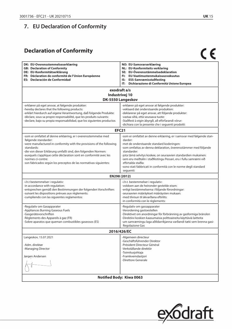
7. EU Declaration of Conformity
Declaration of Conformity
DK: EU-Overensstemmelseserklæring GB: Declaration of Conformity DE: EU-Konformitätserklärung FR: Déclaration de conformité de l’Union Européenne ES: Declaración de Conformidad
NO: EU-Samsvarserklæring NL: EU-Konformiteits verklaring SE: EU-Överensstämmelsedeklaration FI: EU-Vaatimustenmukaisuusvakuutus IS: ESS-Samræmisstaðfesting IT: Dichiarazione di Conformità Unione Europea
exodraft a/sIndustrivej 10
DK-5550 Langeskov -erklærer på eget ansvar, at følgende produkter: -hereby declares that the following products: -erklärt hierdurch auf eigene Verantwortung, daß folgende Produkte: -déclare, sous sa propre responsabilité, que les produits suivants: -declare, bajo su propia responsabilidad, que los siguientes productos
-erklærer på eget ansvar at følgende produkter: -veklaard dat onderstaande produkten: -deklarerar på eget ansvar, att följande produkter: -vastaa siltä, että seuraava tuote: -Staðfesti à eigin àbyrgð, að eftirfarandi vörur: -dichiara con la presente che i seguenti prodotti:
EFC21 -som er omfattet af denne erklæring, er i overensstemmelse med følgende standarder: -were manufactured in conformity with the provisions of the following standards: -die von dieser Erklärung umfaßt sind, den folgenden Normen: -auxquels s’applique cette déclaration sont en conformité avec les normes ci-contre: -son fabricados según los preceptos de las normativas siguientes:
-som er omfattet av denne erklæring, er i samsvar med følgende stan-darder: -met de onderstaande standard koderingen: -som omfattas av denna deklaration, överensstämmer med följande standarder: -jota tämä selvitys koskee, on seuraavien standardien mukainen: -sem eru meðtalin i staðfestingu Pessari, eru i fullu samræmi við eftirtalda staðla: -sono stati fabbricati in conformità con le norme degli standard seguenti:
EN298 (2012)
-i.h.t bestemmelser i regulativ: -in accordance with regulation: -entsprechen gemäß den Bestimmungen der folgenden Vorschriften: -suivant les dispositions prévues aux règlements: -cumpliendo con las siguientes reglamentos:
-i.h.t. bestemmelser i regulativ: -voldoen aan de heironder gestelde eisen: -enligt bestämmelserna i följande förordningar: -seuraavien määräykset määräysten mukaan: -med tilvisun til àkvarðana eftirlits: -in conformità con le règlements:
-Regulativ om Gasapparater -Appliances Burning Gaseous Fuels -Gasgerätevorschriften -Règlements des Appareils à gaz (FR) -Sobre aparatos que queman combustibles gaseosos (ES)
-Regulativ om gassapparater -Verordening gastoestellen -Direktivet om anordningar för förbränning av gasformiga bränslen -Direktiivi koskien kaasumaisia polttoaineita käyttäviä laitteita -um samræmingu laga aðildarríkjanna varðandi tæki sem brenna gasi-Regolazione Gas
2016/426/ECLangeskov, 15.07.2021
-Adm. direktør -Managing Director
Jørgen Andersen
-Algemeen directeur -Geschäftsführender Direktor -Président Directeur Général -Verkställande direktör -Toimitusjohtaja -Framkvemdastjori -Direttore Generale
Notified Body: Kiwa 0063

DK: exodraft a/sIndustrivej 10DK-5550 LangeskovTel: +45 7010 2234Fax: +45 7010 [email protected]
SE: exodraft a/sKalendevägen 2SE-302 39 HalmstadTlf: +46 (0)8-5000 [email protected]
NO: exodraft a/sStorgaten 88NO-3060 SvelvikTel: +47 3329 [email protected]
UK: exodraft Ltd.24 Janes Meadow, TarletonGB-Preston PR4 6NDTel: +44 (0)1494 465 166Fax: +44 (0)1494 465 [email protected]
DE: exodraft GmbHSoonwaldstraße 6DE-55569 MonzingenTel: +49 (0)6751 855 599-0Fax: +49 (0)6751 855 [email protected]
FR: exodraft sas78, rue Paul JozonFR-77300 FontainebleauTel: +33 (0)6 3852 [email protected]
3001
736-
EFC2
1-U
K 20
2107
15