30 years working with jaffre and roberts on modeling flow ... · 30 years working with jaffre and...
TRANSCRIPT
Center for
Subsurface
Modeling
30 Years Working with Jaffre and Roberts on Modeling
Flow in Porous Media
Mary F. Wheeler
ICES Center for Subsurface Modeling
The University of Texas at Austin

Center for
Subsurface
Modeling
Selected Jaffre/ Roberts Computational
Research Contributions
Book: Mathematical Models and Finite Elements for Reservoir Simulation: Single Phase , Multiphase and Multicomponent Flows through Porous Media, Chavent and Jaffre (1986)
Mixed and Hybrid Methods, Roberts and Thomas, (1991)
Upstream Weighting and Mixed Finite Elements in Simulation of Miscible Displacements, Jaffre and Roberts (1983)
On Upstream Mobility Schemes for 2-Phase Flow in Porous Media, Mishra and Jaffre
Decomposition for Flow in Porous Media with Fractures (1999)
Modeling Fractures and Barriers as Interfaces for Flow in Porous Media, Martin, Jaffre, Roberts(2005)
-Godunov Type Methods for Conservation Laws with a Flux Function Discontinuous in Space
Read More: http://epubs.siam.org/doi/abs/10.1137/S1064827503429363
High fidelity algorithms for treating relevant physics -- Complex Nonlinear Systems (coupled near hyperbolic & parabolic/ elliptic systems with possible discrete models)
Locally conservative discretizations (mixed fem, control volume and/or discontinuous Galerkin)
– Multiscale (spatial & temporal multiple scales)
– Multiphysics (Darcy flow, biogeochemistry, thermal, geomechanics)
– Robust Efficient Physics-based Solvers (ESSENTIAL)
– A Posteriori Error Estimators

Center for
Subsurface
Modeling
Resources Recovery
• Petroleum and natural gas recovery from
conventional/unconventional reservoirs
• In situ mining
• Hot dry rock/enhanced geothermal systems
• Potable water supply
• Mining hydrology
Societal Needs in Relation to Geological Systems
Site Restoration
• Aquifer remediation
• Acid-rock drainage
Waste Containment/Disposal
• Deep waste injection
• Nuclear waste disposal
• CO2 sequestration
• Cryogenic storage/petroleum/gas
Underground Construction
• Civil infrastructure
• Underground space
• Secure structures

Center for
Subsurface
Modeling
Acknowledge
Mojdeh Delshad, Changli Yuan,
Andro Mikelic, Ivan Yotov,
Thomas Wick, Gergina Pencheva,
Vivette Girault, Kundan Kumar,
Gurpreet Singh.
Jaffre/ Roberts: Mixed Methods,
Multiphase Flow, Reactive Transport, Miscible Displacement and
Fingering, DG, Fracture Modeling,

Center for
Subsurface
Modeling
Outline (Work Motivated by Jaffre/Roberts)
• Multipoint Flux Mixed Finite Element Method
(MFMFE) for Flow and Coupling with Geomechanics
– Example: poroelasticity with fixed fractures
• Chemical EOR: Polymer Flow and ASP (alkaline,
surfactant, polymer)
• EOS Compositional Flow
– Formulation
– Brugge Co2 EOR
– Coupling with EnKF for In Salah Co2 Sequestration
• Conclusions

Center for
Subsurface
Modeling
Single Phase Flow
• Q represents the quadrature rule

Center for
Subsurface
Modeling
Corner Point Geometry - Highly Distorted Hexahedra

Center for
Subsurface
Modeling
Multipoint Flux Mixed Finite Element
• Provably accurate:
• Pressure to second order;
• Velocity to first order.
• Locally mass conservative.
• Easy to implement.
• Current Extensions:
• Non-isothermal compositional
model.
• Nonplanar fractured grids.

Center for
Subsurface
Modeling
Fractured Reservoir Flow Model
• Interface as pressure specified BC for reservoir
• No-flow BC for fracture
• Jump in reservoir flux across interface as the source term for fracture

Center for
Subsurface
Modeling
Model Formulation
Interface Conditions
Reservoir Flow Fracture Flow
Center for
Subsurface
Modeling
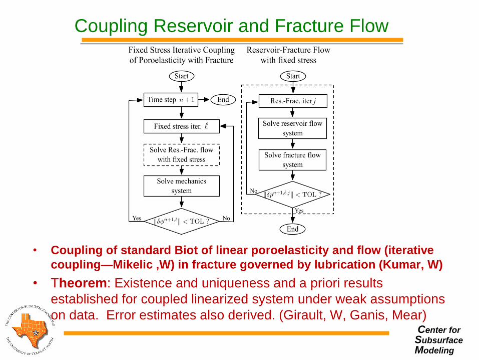
Coupling Reservoir and Fracture Flow
• Coupling of standard Biot of linear poroelasticity and flow (iterative
coupling—Mikelic ,W) in fracture governed by lubrication (Kumar, W)
• Theorem: Existence and uniqueness and a priori results
established for coupled linearized system under weak assumptions
on data. Error estimates also derived. (Girault, W, Ganis, Mear)
Center for
Subsurface
Modeling
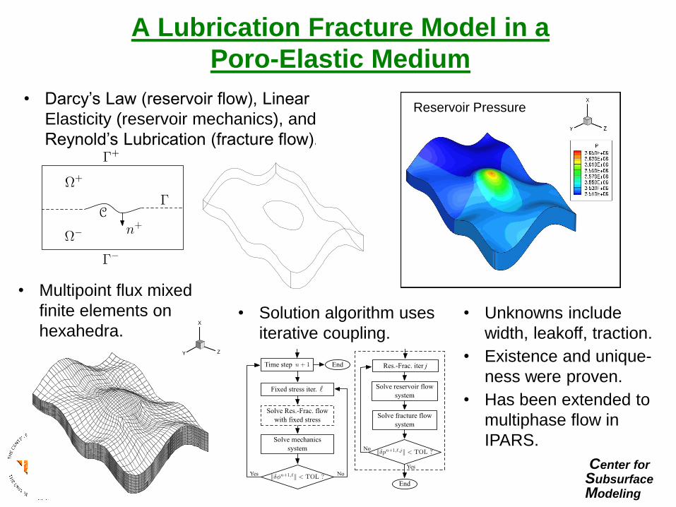
A Lubrication Fracture Model in a
Poro-Elastic Medium
• Darcy’s Law (reservoir flow), Linear
Elasticity (reservoir mechanics), and
Reynold’s Lubrication (fracture flow).
• Multipoint flux mixed
finite elements on
hexahedra. • Solution algorithm uses
iterative coupling.
• Unknowns include
width, leakoff, traction.
• Existence and unique-
ness were proven.
• Has been extended to
multiphase flow in
IPARS.
Fracture width Fluid leakoff Pres on Distorted Grid Reservoir Pressure

Center for
Subsurface
Modeling
Motivation for Chemical EOR Studies
Improve oil recovery efficiency for displacements with unfavorable mobility ratio and very heterogeneous reservoirs
Target bypassed oil left after waterflood
Reduce mobility ratio to improve areal and vertical sweep efficiencies
Compare efficiency/accuracy of different numerical schemes (IMPES, IMPLICIT, Iterative Coupling, Time splitting)
Process scale up to field scale
Chemical EOR in fractured porous media, e,g, Alaska

Center for
Subsurface
Modeling
Improved Mobility & Sweep Efficiency

Center for
Subsurface
Modeling
Polymer Structure
Large chains of repeating monomers
linked by covalent bonds
Polyacrylamide (MW ~ 2- 30 MM) Xanthan (MW ~ 2- 50 MM)

Center for
Subsurface
Modeling
Mobility Ratio
The ratio of displacing
fluid mobility to displaced
fluid mobility:
w w kk w owMk ko o o o w
Source: Lake, 1989
1M
Piston-like displacement
Small amount of polymer
increases water viscosity

Center for
Subsurface
Modeling
Polymer Rheology
Dilute polymer solutions are
pseudoplastic (shear thinning)
Power law
NewtonianNewtonian

Center for
Subsurface
Modeling
IPARS-TRCHEM
Two phase oil/water
Compressible fluids
MFMFE Based
Time split method for flow and concentration (transport, diffusion/ dispersion)
Non-differentiable inequality constraints – model as minimization of Gibbs free energy using interior pt.
Several boundary condition options
Wells as volumetric or pressure constraint
AMG solver with pre-conditioner
Parallel computation capability
General geochemistry and biochemistry modules

Center for
Subsurface
Modeling
Polymer Properties in IPARS-TRCHEM
Viscosity as a function of
Concentration
Salinity
Shear rate
Adsorption
Permeability reduction
Inaccessible pore volume

Center for
Subsurface
Modeling
Chemical Flooding Modules
• Surfactant – Reduce the interfacial tension between oil and water
phases
– Target bypassed oil left after waterflood by mobilizing oil trapped in pores due to capillary pressure/force
• Polymer – Reduce water mobility to improve areal and vertical
sweep efficiencies
– Target bypassed oil left after waterflood due to unfavorable mobility ratio and heterogeneity
• Model field-scale tests using parallel computation
Center for
Subsurface
Modeling
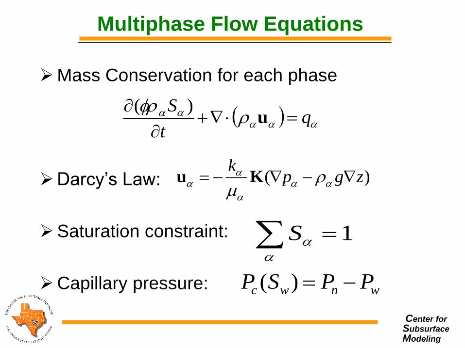
Multiphase Flow Equations
Mass Conservation for each phase
Darcy’s Law:
Saturation constraint:
Capillary pressure:
( )k
p g z
u K
1
S
wnwc PPSP )(
q
t
S
u
)(

Center for
Subsurface
Modeling
Reactive Species Transport Model
• Mass balance of species i in phase α :
• An equilibrium linear partition between phases
• Phase-summed species transport equation:
i
C
iiiii qRScDSuct
Sc
)(
)(
ci icir
TC
i
T
iiwiiiwiwi RqcDuc
t
c
)(
)( ***
)(*
oiowi SS oiowi uuu
*
)(*
ioiooiwwi DSDSD
oiow
T
i qqq
)( C
ioo
C
iww
TC
i RSRSR

Center for
Subsurface
Modeling
Component Transport Equations
Mass balance of species i in phase α :
The diffusion-dispersion tensor Di is given
by:
iqiciDSuic
t
)Sic(
hydmol
iii DDD
)(hyd velocityfi D

Center for
Subsurface
Modeling
Validation against an IMPES Code
Cum. Oil Rec. Vs. Time
0
0.02
0.04
0.06
0.08
0.1
0.12
0.14
0.16
0.18
0 200 400 600 800 1000 1200 1400 1600 1800
Time (Days)
Np
d (
fracti
on
of
OO
IP)
UTCHEM IPARS
Total Inj. Rate Vs. Time : (inj)
0
500
1000
1500
2000
2500
3000
3500
4000
0 300 600 900 1200 1500
Time (Days)
qin
j (ft
3/d
)
Bottom Hole Pressure Vs. Time : (inj)
0
2000
4000
6000
8000
10000
12000
0 300 600 900 1200 1500
Time (Days)
PB
H (
psi)
UTCHEM IPARS
Polymer Injection Concentration Vs. Time : (inj)
0
0.02
0.04
0.06
0.08
0.1
0.12
0 300 600 900 1200 1500
Time (Days)
Cp (
wt%
)

Center for
Subsurface
Modeling
Parallel Simulation of Polymer Injection
200 cp oil viscosity (endpoint mobility ratio = 107)
Domain size : 10240 ft x 5120 ft x 160 ft
Grid size: 20 ft x 10 ft x 10 ft
No. of gridblocks : 4,194,304
Average perm. : (about 10 D)
32 five spots with 37.6 acre well patterns
32 injection wells and 45 production wells
Constant pressure injection (below parting pressure)
128 processors

Center for
Subsurface
Modeling
Polymer Flood Simulations
Permeability, md
Polymer conc. Oil saturation

Center for
Subsurface
Modeling
37.50
58.27
3.68
40.63
0.0
10.0
20.0
30.0
40.0
50.0
60.0
WF 10cp PF 10cp WF 200cp PF 200cp
Cu
mu
lati
ve O
il R
eco
very
(%
OO
IP)
Polymerflood Recovery for Viscous Oil
3.43 PV
0.87 PV
21 PV
0.78 PV
2000 days 4000 days

Center for
Subsurface
Modeling
Parallel Scalability
CPU Time
Parallel Scalability
39.77
21.40
0.0
10.0
20.0
30.0
40.0
50.0
128Processors 256 Processors
CP
U tim
e (h
rs)
0
0.5
1
1.5
2
2.5
0 128 256 384
Spe
ed
up
Number of Processors
Ideal Speedup
Actual Speedup

Center for
Subsurface
Modeling
ASP Model Species
Polymer flood: 3+ species, the first 3 species must be
polymer, anion (Cl-), cation (Ca2+)
SP flood: 4+ species, the first 4 species must be polymer,
anion (Cl-), cation (Ca2+), surfactant
ASP flood: 12+ species, the first 12 species must be
polymer, anion (Cl-), cation (Ca2+), surfactant, H+, HAo,
CO32-, Na+, Mg2+, A-, HAw, OH-
Center for
Subsurface
Modeling
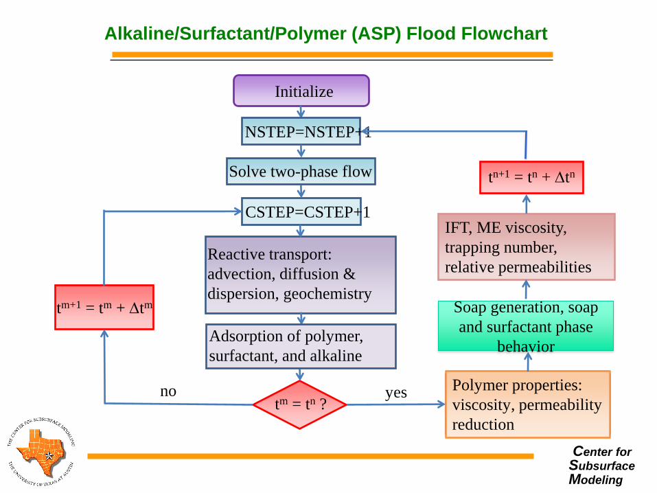
Alkaline/Surfactant/Polymer (ASP) Flood Flowchart
Initialize
NSTEP=NSTEP+1
Solve two-phase flow
CSTEP=CSTEP+1
Reactive transport:
advection, diffusion &
dispersion, geochemistry
Adsorption of polymer,
surfactant, and alkaline
tm = tn ?
tm+1 = tm + tm
no Polymer properties:
viscosity, permeability
reduction
IFT, ME viscosity,
trapping number,
relative permeabilities
tn+1 = tn + tn
yes
Soap generation, soap
and surfactant phase
behavior
Center for
Subsurface
Modeling
Alkaline/Surfactant/Polymer Module Features
• Polymer, surfactant, and alkaline adsorptions
• Non-Newtonian polymer solution and micoremulsion
(ME) viscosities
• Permeability reduction and pore volume reduction
• In situ generation of soap by reaction of alkaline with the
acid in crude oil
• Phase behavior as a function of soap and surfactant
concentrations
• Aqueous geochemical reactions, mineral
dissolution/precipitation, and ion exchange with clays in
the rock and micelles

Center for
Subsurface
Modeling
Field-scale unstable polymer flood
• Reservoir dimensions: 1024 x 256 x 256 (ft)
• Gridblocks in each direction: 128 x 64 x 128
• Gridblock sizes: 8 x 4 x 2 (ft)
• Total gridblocks: 1,048,576
• Number of processors : 64
• Simulation time: 100 Day

Center for
Subsurface
Modeling
Field-scale unstable polymer flood (Cont.)
• Average permeability: 2100md
• Porosity: 0.23
• Oil viscosity: 2000cp
• 1 horizontal injector at the bottom with PBH= 15000psi
• 1 horizontal producer at the top with PBH= 3000psi
• Injection rate: about 2600~3000STB/Day
• Injected polymer conc.: 0.07497lbmol/ft3 (0.12wt%)

Center for
Subsurface
Modeling
Polymer Viscosity

Center for
Subsurface
Modeling
Relative Permeabilities

Center for
Subsurface
Modeling
Relative Permeabilities

Center for
Subsurface
Modeling
Permeability Distribution and Well Locations
Producer
Injector

Center for
Subsurface
Modeling
Simulation Results at 100 Day

Center for
Subsurface
Modeling
Simulation Results at 100 Day (Cont.)

Center for
Subsurface
Modeling
Compositional Equations
Define Component Flux
Modified Compositional Equations
Component Conservation Equation
Darcy Phase Flux
64

Center for
Subsurface
Modeling
Closure & Constraints
Saturation Constraint Capillary Pressure
Phase Behavior
Rock Compressibility
65

Center for
Subsurface
Modeling
Hydrocarbon Phase Behavior
Peng-Robinson Cubic EOS
Rachford-Rice for phase mole fraction (ν)
Iso-fugacity criteria for Kipar
Gibbs energy minimization for phase stability
66

Center for
Subsurface
Modeling
Discrete Form
Component Flux
Component Conservation Equation
• Enhanced BDDF1 mixed finite element space
• Symmetric and non-symmetric quadrature rules (Q)
• 9 and 27 point stencil for 2 and 3 dimensions, respectively
• Λis are positive quantities
67

Center for
Subsurface
Modeling
Diffusion-Dispersion
Diffusive-Dispersive Flux Calculation
Full Tensor Diffusion-Dispersion
• Accurate dispersion tensor calculation using flux vector at each corner
• Reduced grid-orientation effect on concentrations
68

Center for
Subsurface
Modeling
Linearized Form
Component Flux
Component Mass Conservation
• Eliminate fluxes δFi to obtain a linear system of
equations in δP and δNi
69

Center for
Subsurface
Modeling
Linearized Form
Saturation Constraint
Fugacities at Equilibrium
• Eliminate fluxes δKpar and δν to obtain a linear system of
equations in δP and δNi
70

Center for
Subsurface
Modeling
Brugge Field Study
Brugge field geometry and well locations
71

Center for
Subsurface
Modeling
• 9x48x139 general hexahedral elements
• In-situ hydrocarbon fluid composition: 40% C6, 60% C20
• Injected fluid composition: 100 % CO2
• Initial reservoir pressure: 1500 psi
• 30 bottom-hole pressure specified wells
– 10 injectors at 3000 psi
– 20 producers at 1000 psi
• Initial water saturation: Sw = 0.2
• φ ≈ 0.14 - 0.24, Kz = Ky, Tres = 160 F
72
Reservoir Properties

Center for
Subsurface
Modeling
Rock Properties
Relative Permeability Curves
Capillary Pressure Curves
73

Center for
Subsurface
Modeling
Pressure & Concentration Profiles
Pressure and concentration profiles after 1000 days 74

Center for
Subsurface
Modeling
Saturation Profiles
• Multi-contact miscible flood
• Miscibility achieved at the tail end of the displacement
front
Saturation profiles after 1000 days
75

Center for
Subsurface
Modeling
Hydraulic Fracturing Stages
• Fracture growth: slick water injection
– Length
• Proppant placement: polymer injection
– Width due to polymer injection
– Thickness due to proppant
• Compaction

Center for
Subsurface
Modeling
Proppant Placement
Proppan
t
Polym
er
Slick
Water

Center for
Subsurface
Modeling
Well Model Updates
• Multistage hydraulic fractures in a single
well bore

Center for
Subsurface
Modeling
Characteristics
• Polymer front travels ahead of proppant front
• Initial fracture thickness due to fracture
growth during slick water injection
• Intermediate thickness increase due to fluid
pressure front ahead of proppant front
• Final thickness related to proppant
concentration
• Compaction related width changes

Center for
Subsurface
Modeling
Phase Field for Crack Propagation (Mikelic, W, Wick)
Four advantages
Fixed-mesh approach
avoiding remeshing
Crack nucleation,
propagation and path are
included in the model
avoiding evaluation of stress
intensity factors
Joining and branching of
multiple cracks easy to
realize
Cracks in heterogeneous
media

Center for
Subsurface
Modeling
Energized Fractures
82

Center for
Subsurface
Modeling
In Salah Reservoir
• Salah Gas Project in Algeria is world’s first industrial scale
CO2 storage project in depleting gas field
• Aprox. 0.5-1 M tons CO2 per year injected since August 2004
• Aquifer: low-permeability, 20 m thick carboniferous sandstone,
1800-1900 m deep
Schematic vertical cross section through the Krechba field (Rutqvist
et al., 2009)

Center for
Subsurface
Modeling
In Salah Reservoir
• Three long-reach (about 1-1.5 km) horizontal injection wells
• Satellite-based inferrometry (InSAR) has been used for
detecting ground surface deformations related to the CO2
injection
• Uplift occurred within a month after start of the injection and
the rate of uplift was approximately 5 mm per year (∼2 cm for 4
years over the injection wells)
Vertical displacements at 3 years (left) and time evolution of vertical displacement for a location above KB501 (right)
(Rutqvist et al., 2009)

Center for
Subsurface
Modeling
In Salah Reservoir
• The main CO2 storage aquifer (C10.2)
is approximately 20–25m thick.
• The C10.2 formation is overlain by a
tight sandstone and siltstone
formation (C10.3) of about 20m in
thickness.
• The C10 formation, together with the
lower cap rock (C20.1–C20.3), form
the CO2 storage complex at Krechba.
• It has been shown that most of the
observed uplift may be attributed to
the poroelastic expansion of the 20m
thick storage formation, but a
significant contribution could come
from pressure-induced deformation
within a larger zone (∼100m thick) of
shale sands immediately above the
injection zone (Rutqvist et al. (2009) ).
After Ringrose
(2007)
Center for
Subsurface
Modeling
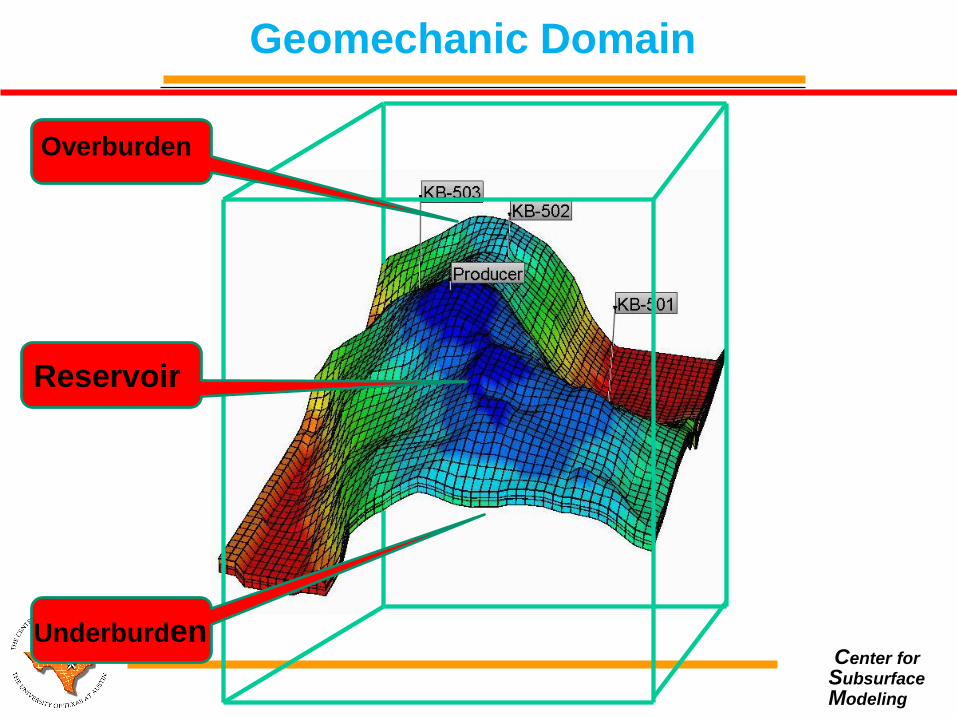
Geomechanic Domain
Overburden
Underburden
Reservoir

Center for
Subsurface
Modeling
Summary
Dynamic flow data (BHP and CO2 saturation) and surface
deformation very sensitive to geomechanical properties of the
formation such as Young’s modulus and Poisson ratio.
Reservoir traction an important source of uncertainty in
injection and production data.
Integration of geomechanical observed data in addition to flow
data should be considered for better reservoir characterization.
Future plan: Full field reservoir simulation and characterization
of In Salah reservoir using observed data from three injection
wells and surface uplift InSAR data.

Center for
Subsurface
Modeling
Conclusions
• General hexahedral elements to handle complex
reservoir geometries
• Full tensor permeability and dispersion
• Locally mass conservative and accurate flux description
• Reduced grid orientation effect on pressure and
concentration
• Integration of single, two, black oil, and compositional
formulations under a single MFMFE framework
• Extension to coupled ASP and/or compositional flow and
geomechanics for fractured reservoirs
• Coupling with phase field for fracture propagation
88

Center for
Subsurface
Modeling