3.0 user guide - pos7.tistory.com241ef... · ncr realscan 75 ... this book is written for hardware...
TRANSCRIPT

NCR RealScan 75 (7875) Scanner/Scale Release 3.0
User Guide
RealScan7875-3xxx
RealScan7875-1xxx/2xxx
16346
RealScan7875-4xxx
RealScan7875-7xxx/8xxx
B005‐0000‐1085 Issue M

The product described in this book is a licensed product of NCR Corporation.
NCR is a registered trademark of NCR Corporation.
NCR RealPOS, NCR RealPrice, NCR RealScan, NCR EasyPoint and NCR FastLane are either registered trademarks or trademarks of NCR Corporation in the United States and/or other countries.
It is the policy of NCR Corporation (NCR) to improve products as new technology, components, software, and firmware become available. NCR, therefore, reserves the right to change specifications without prior notice.
All features, functions, and operations described herein may not be marketed by NCR in all parts of the world. In some instances, photographs are of equipment prototypes. Therefore, before using this document, consult with your NCR representative or NCR office for information that is applicable and current.
To maintain the quality of our publications, we need your comments on the accuracy, clarity, organization, and value of this book.
Address correspondence to:
Manager, Information Products NCR Corporation 2651 Satellite Blvd. Duluth, GA 30096
Copyright © 2007 By NCR Corporation Dayton, Ohio U.S.A. All Rights Reserved

i
Preface Audience This book is written for hardware installer/service personnel, system integrators, and field engineers.
Notice: This document is NCR proprietary information and is not to be disclosed or reproduced without consent.

ii
References • NCR Scanner Programming Tags
Needed to set programming parameters in the RealScan 75. (BST0‐2121‐74)
• NCR Scanner/Scale Interface Programmer’s Guide Provides information about the RealScan 75 communications with the Host Terminal. Needed by the POS Application developer. (BD20‐1074‐A)
• NCR RealScan 75 Repair Guide Provides information needed to service the RealScan 75. (B005‐0000‐1086)
Note: Detailed information about the Bizerba Computing scale© is developed by the Bizerba Corporation© and distributed with the scale.

iii
Table of Contents
Chapter 1: Product Overview
Available Models.................................................................................. 1‐2 Features/Options .................................................................................. 1‐5
Bi‐Optic Scanning .......................................................................... 1‐5 Discriminating Among Bar Codes............................................... 1‐7 Displays........................................................................................... 1‐8 Dual Peripheral Ports .................................................................... 1‐9 Firmware Flashing—Super ASIC .............................................. 1‐10 Interface Types ............................................................................. 1‐10 Not On File.................................................................................... 1‐10 PACESETTER............................................................................... 1‐11
PACESETTER Plus .................................................................. 1‐11 PACESETTER III...................................................................... 1‐12
Power Supply ............................................................................... 1‐12 Programming the RealScan 75 ................................................... 1‐13 GS1 DataBar.................................................................................. 1‐14
GS1 DataBar‐14 ........................................................................ 1‐14 GS1 DataBar‐14 Stacked ......................................................... 1‐15 GS1 DataBar Expanded .......................................................... 1‐15 GS1 DataBar Expanded Stacked............................................ 1‐15
Scan Doctor ................................................................................... 1‐16 Power‐On Wellness Check..................................................... 1‐16 Ongoing Wellness Check........................................................ 1‐16 Service Diagnostics.................................................................. 1‐16
Servicing the RealScan 75 ........................................................... 1‐17 Soft Power Down/Power Up...................................................... 1‐17

iv
Voice Messages............................................................................. 1‐18 Volume Adjust Button ................................................................ 1‐18 Window Maintenance Indicator ................................................ 1‐19
Interface Cables................................................................................... 1‐20 Host Terminals ............................................................................. 1‐20
NCR Host Terminals ............................................................... 1‐20 Casio Host Terminals.............................................................. 1‐21 Datachecker Host Terminals.................................................. 1‐21 Epson Host Terminals............................................................. 1‐21 Fujitsu Host Terminals............................................................ 1‐21 Gilbarco Host Terminals......................................................... 1‐21 IBM Host Terminals ................................................................ 1‐22 ICL Host Terminals ................................................................. 1‐22 Microbilt Host Terminals ....................................................... 1‐22 NEC Host Terminals ............................................................... 1‐23 SASI Host Terminals ............................................................... 1‐23 Siemens Nixdorf Host Terminals .......................................... 1‐23 TEC Host Terminals ................................................................ 1‐23 Verifone Host Terminals ........................................................ 1‐23 Wayne Host Terminals ........................................................... 1‐24 Wedge Host Terminals ........................................................... 1‐24
Chapter 2: Site Requirements
Customer Responsibilities ............................................................ 2‐1 Environment Considerations ....................................................... 2‐2 Installation Location ...................................................................... 2‐3
Checkstand Cutout—RealScan 75‐1xxx/2xxx ........................ 2‐5 Checkstand Cutout—RealScan 75‐7xxx/8xxx ........................ 2‐6 Checkstand Cutout—RealScan 75‐3xxx ................................. 2‐7

v
Checkstand Cutout—RealScan 75‐4xxx ................................. 2‐8 RealScan 25 Remote Compact Display Dimensions............. 2‐9 Hole Requirements For Cables .............................................. 2‐10 Ventilation Requirements....................................................... 2‐10
Physical Characteristics............................................................... 2‐11 Weight ....................................................................................... 2‐11 Display Clearance.................................................................... 2‐12 Service Clearance..................................................................... 2‐13
Preparing the Site......................................................................... 2‐14 Power Considerations ................................................................. 2‐15
Power Application................................................................... 2‐15 Checkstand Wiring.................................................................. 2‐16
Power Transient Protection ........................................................ 2‐17
Chapter 3: Installing Information
Step 1–Verify That Unit Is Ready To Install ..................................... 3‐2 Reporting a Damaged RealScan 75.............................................. 3‐2 What is in the Box .......................................................................... 3‐2 Cable Verification .......................................................................... 3‐2 Checkstand Verification................................................................ 3‐3
Step 2–Install the Unit.......................................................................... 3‐4 Complete the Installation.............................................................. 3‐5
RealScan 75‐2xxx/8xxx Units.................................................... 3‐5 RealScan 75‐1xxx/3xxx/7xxx Units .......................................... 3‐5 RealScan 75‐4xxx Units ............................................................. 3‐5
Step 3–Calibrate the Scale.................................................................... 3‐6 Exercise the Scale ........................................................................... 3‐8 Access the Calibration Switch ...................................................... 3‐8
RealScan 75‐2xxx........................................................................ 3‐8

vi
RealScan 75‐8xxx........................................................................ 3‐9 Connect the Field Service Calibration Display ........................ 3‐10 Perform Calibration Procedure.................................................. 3‐11 Increasing Load Test.................................................................... 3‐13 Over‐Capacity Test ...................................................................... 3‐14 Decreasing Load Test .................................................................. 3‐14 Shift Test........................................................................................ 3‐15 Secure the Calibration Switch .................................................... 3‐16
RealScan 75‐2xxx...................................................................... 3‐16 RealScan 75‐8xxx...................................................................... 3‐18
Step 4–Determine If Unit Is Operational......................................... 3‐20 NCR RealScan 75‐1xxx/3xxx/4xxx/7xxx Scanner..................... 3‐20 NCR RealScan 75‐2xxx/8xxx Scanner/Scale.............................. 3‐20 If the RealScan 75 Does Not Pass Level O Diagnostics .......... 3‐20 Checkout Reading Operation..................................................... 3‐21 Check Sensormatic® Deactivation System............................... 3‐21 Programming................................................................................ 3‐21 Determine Communication Protocol ........................................ 3‐21
Special Installations............................................................................ 3‐23 Convenience Stores...................................................................... 3‐23 RealScan 2170 Host Terminal..................................................... 3‐24
Programming the RealScan 75‐1xxx/3xxx/7xxx................... 3‐24 Setting up the NCR 2170 Terminal ....................................... 3‐25
Scale Address for IBM Communications.................................. 3‐26 SNI Beetle Terminal..................................................................... 3‐27 Special RS‐232 Peripheral Port Connections ............................ 3‐28 Metrologic MS951 ........................................................................ 3‐28
Verify Installation .................................................................... 3‐30 Metrologic MS951 Hand‐Held Scanner Programming ...... 3‐31

vii
RealScan 32 Hand‐Held Scanner........................................... 3‐32 RealScan 35/36 Hand‐Held Scanner connection ................. 3‐34 RealScan 37 Hand‐Held Scanner Connection...................... 3‐36 External Sensormatic® Tag Deactivation System............... 3‐39 Symbol Technologies LS4000................................................. 3‐40
Chapter 4: Operating Information
Scanner/Scale Components ................................................................. 4‐2 Motion Detector ............................................................................. 4‐3 Volume Adjust Button .................................................................. 4‐3 Window Maintenance Indicator .................................................. 4‐4 Scale Zero Button ........................................................................... 4‐4 Status Indicator .............................................................................. 4‐5 Speaker (Audible Tone/Voice Messages) ................................... 4‐5 Operator Display Panel................................................................. 4‐6 Integrated Display ......................................................................... 4‐6 Remote Display .............................................................................. 4‐7 Vertical Scan Window................................................................... 4‐7 Top Plate.......................................................................................... 4‐7 Horizontal Scan Window.............................................................. 4‐8
Barcode Label Orientation .................................................................. 4‐9 Active Scan Zone............................................................................ 4‐9 Bar Code Quality.......................................................................... 4‐10 Multiple Reads ............................................................................. 4‐11
Operating Instructions....................................................................... 4‐12 Adjusting the Good Read Tone.................................................. 4‐12 Not‐On‐File Error......................................................................... 4‐13 Scanning Procedure ..................................................................... 4‐13 Turning the RealScan 75 On And Off ....................................... 4‐14

viii
Scanner/Scale Model ............................................................... 4‐15 Scanner Only Model................................................................ 4‐15
Weighing Procedure.................................................................... 4‐15 Operating the Sensormatic® Deactivation System .................. 4‐17
Normal Operation ................................................................... 4‐17 Manual Deactivation............................................................... 4‐18
Cleaning Procedure............................................................................ 4‐19 Scanner Body............................................................................ 4‐19 Vertical Scan Window............................................................. 4‐19 Top Plate/Horizontal Scan Window/Produce Guard......... 4‐19
Chapter 5: Troubleshooting
Troubleshooting Aids .......................................................................... 5‐2 Error Codes ..................................................................................... 5‐2 Scanner Problems........................................................................... 5‐4 Scale Problems................................................................................ 5‐5 Bizerba Scale Problems ................................................................. 5‐6 Sensormatic® Deactivation Problems......................................... 5‐7
Voice Messages .......................................................................... 5‐7 Tones ........................................................................................... 5‐8
Chapter 6: Programming Information
How to Program the RealScan 75....................................................... 6‐2 Creating the Program.................................................................... 6‐2
Write the Program..................................................................... 6‐2 Enter the Program ..................................................................... 6‐2 Save the Program....................................................................... 6‐3
Programming Mode ...................................................................... 6‐3 Programming Tags ........................................................................ 6‐5

ix
Abort............................................................................................ 6‐5 Default......................................................................................... 6‐6 End............................................................................................... 6‐6 Hex 0 ‐ Hex F.............................................................................. 6‐6 Programming Mode.................................................................. 6‐7 Save and Reset ........................................................................... 6‐7 Reset ............................................................................................ 6‐7
Program Entry Example................................................................ 6‐8 Program Defaults ......................................................................... 6‐12
Communications Protocol ...................................................... 6‐12 Good Read Tone ...................................................................... 6‐12 Timers........................................................................................ 6‐12 Bar Codes–1.............................................................................. 6‐12 Bar Codes–2.............................................................................. 6‐13 Bar Codes–3.............................................................................. 6‐13 Bar Codes–4.............................................................................. 6‐13 Bar Codes–5.............................................................................. 6‐14 Bar Codes–6.............................................................................. 6‐14 Label Identifiers ....................................................................... 6‐14 RS‐232 Parameters–1 ............................................................... 6‐14 RS‐232 Parameters–2 ............................................................... 6‐15 RS‐232 Prefix Byte.................................................................... 6‐15 RS‐232 Terminator Byte .......................................................... 6‐15 RS‐232 Communications Options ......................................... 6‐15 Scale Parameters ...................................................................... 6‐16 Miscellaneous Parameters ...................................................... 6‐16 Dual Cable Interface................................................................ 6‐16
Programming Tips ....................................................................... 6‐17 Parameter Descriptions ..................................................................... 6‐18

x
Communications Protocol .......................................................... 6‐18 Sample Program ...................................................................... 6‐18 Program Parameters................................................................ 6‐18
Good Read Tone........................................................................... 6‐22 Sample Program ...................................................................... 6‐22 Program Parameters................................................................ 6‐22
Timers ............................................................................................ 6‐23 Sample Program ...................................................................... 6‐23 Program Parameters................................................................ 6‐24
Bar Codes–1 .................................................................................. 6‐25 Sample Program ...................................................................... 6‐25 Program Parameters................................................................ 6‐26
Bar Codes–2 .................................................................................. 6‐28 Sample Program ...................................................................... 6‐28 Program Parameters................................................................ 6‐30
Bar Codes–3 .................................................................................. 6‐32 Program Parameters................................................................ 6‐33
Bar Codes–4 .................................................................................. 6‐35 Sample Program ...................................................................... 6‐35 Program Parameters................................................................ 6‐36
Bar Codes–5 .................................................................................. 6‐38 Sample Program ...................................................................... 6‐38 Program Parameters................................................................ 6‐39
Bar Codes–6 .................................................................................. 6‐40 ISBN‐10 and ISBN‐13 .............................................................. 6‐40 ISSN ........................................................................................... 6‐41
Label Identifiers ........................................................................... 6‐42 Sample Program ...................................................................... 6‐42 Program Parameters................................................................ 6‐44

xi
RS‐232 Parameters–1 ................................................................... 6‐47 Sample Program ...................................................................... 6‐47 Program Parameters................................................................ 6‐48
RS‐232 Parameters–2 ................................................................... 6‐50 Sample Program ...................................................................... 6‐50 Program Parameters................................................................ 6‐51
RS‐232 Prefix Byte ........................................................................ 6‐52 Sample Program ...................................................................... 6‐52 Program Parameters................................................................ 6‐53
RS‐232 Terminator Byte .............................................................. 6‐53 Sample Program ...................................................................... 6‐54 Program Parameters................................................................ 6‐54
RS‐232 Communications Options.............................................. 6‐55 Sample Program ...................................................................... 6‐55 Program Parameters................................................................ 6‐55
Scale Parameters .......................................................................... 6‐59 Sample Program ...................................................................... 6‐59 Program Parameters................................................................ 6‐59
Miscellaneous Parameters .......................................................... 6‐60 Sample Program ...................................................................... 6‐60 Program Parameters................................................................ 6‐61
Dual Cable Interface .................................................................... 6‐63 Sample Program ...................................................................... 6‐64 Program Parameters................................................................ 6‐64
PACESETTER Information ............................................................... 6‐66 PACESETTER Plus ...................................................................... 6‐66
Mode 1— Inquiry .................................................................... 6‐66 Mode 2—Real Time................................................................. 6‐67 Mode 3—Normal ..................................................................... 6‐69

xii
Host Access to Tallies.............................................................. 6‐71 Host Reset of Tallies ................................................................ 6‐75
PACESETTER III .......................................................................... 6‐76 PACESETTER III Correction.................................................. 6‐76 PACESETTER III Detection.................................................... 6‐77 PACESETTER III Tallies ......................................................... 6‐78
Special Programming......................................................................... 6‐79 Belt Read Detection...................................................................... 6‐79 Changing Program Defaults to Current Parameters .............. 6‐79
Firmware Break‐in................................................................... 6‐79 Enable Soft Defaults ................................................................ 6‐80 Disable Soft Defaults ............................................................... 6‐80
Code 128 Overlap Characters..................................................... 6‐81 Convert UPC‐E Tags into EAN‐13 Tags ................................... 6‐81 EAN/JAN/UPC Multi‐Symbol Scanning Parameters ............. 6‐82
Label Construction .................................................................. 6‐82 Single Label Restriction .......................................................... 6‐82 Transmitting Label Data......................................................... 6‐82
Early Beep Disable ....................................................................... 6‐83 Enable/Disable Code 128 Partials .............................................. 6‐84 Good Read Tone Presets ............................................................. 6‐85 IBM 4694 Configuration Command .......................................... 6‐86 Programming Multi‐Symbol Scanning..................................... 6‐86 Programming the Scale for High Checkstand Vibration........ 6‐87
Firmware Break‐in................................................................... 6‐87 GS1 DataBar.................................................................................. 6‐88
Enable GS1 DataBar ................................................................ 6‐88 Send GS1 DataBar14 as EAN13 Tag Data ............................ 6‐88
Reset Function .............................................................................. 6‐89

xiii
Scanning UPC/EAN/JAN Tags Without a Center Band......... 6‐89 Sensormatic® Deactivation System........................................... 6‐89
Download RealScan 75 Parameters to ScanMax™ Pro Controller.................................................................................. 6‐90 Set ScanMax™ Pro Controller Parameters at the Controller.................................................................................. 6‐90 Specific Function Programming ............................................ 6‐91
Terminal Coupon Interface Parameters.................................... 6‐92 Terminal Coupon Select 1 Parameters.................................. 6‐93 Set Terminal Coupon Select 2 Parameter ............................. 6‐94
Volume Adjust Button ................................................................ 6‐94 Volume Adjust Button Settings ............................................. 6‐95
Window Maintenance Indicator ................................................ 6‐97 Firmware Flashing (for RealScan 75 SA Scanners) ........................ 6‐98
Obtaining New Firmware........................................................... 6‐98 Acquiring and Installing the EasyFlash Software ................... 6‐99 Acquiring and Installing the NCR RealScan Flash Tool for Windows ..................................................................................... 6‐101 Firmware Flashing Procedure.................................................. 6‐103
Operating EasyFlash Software............................................. 6‐104 Operating NCR RealScan Flash Tool .................................. 6‐106
Flash Utility Notes ..................................................................... 6‐108 Checking RealScan 75 Scanner Firmware Level ............... 6‐108
EasyFlash Firmware Flash Troubleshooting Guide.............. 6‐111 NCR Flash Tool Firmware Flash Troubleshooting Guide ... 6‐115
Programming Worksheets .............................................................. 6‐116 Using Programming Worksheets ............................................ 6‐116
Purpose ................................................................................... 6‐116 Format ..................................................................................... 6‐116

xiv
Shortcuts ................................................................................. 6‐116 Communications Protocol ........................................................ 6‐117
Single/Dual ASIC................................................................... 6‐117 Communications Protocol ........................................................ 6‐118
Super ASIC ............................................................................. 6‐118 Good Read Tone......................................................................... 6‐119 Timers .......................................................................................... 6‐120
All Models .............................................................................. 6‐120 Release 1.................................................................................. 6‐121 Release 2.................................................................................. 6‐122
Bar Codes–1 ................................................................................ 6‐123 Single/Dual ASIC................................................................... 6‐123 Super ASIC ............................................................................. 6‐124
Bar Codes–2 ................................................................................ 6‐125 Bar Codes–3 ................................................................................ 6‐126 Bar Codes–4 ................................................................................ 6‐127 Bar Codes–5 ................................................................................ 6‐128 Bar Codes–6 ................................................................................ 6‐129 Label Identifiers ......................................................................... 6‐130 Sensormatic Beep ....................................................................... 6‐131 RS‐232 Parameters–1 ................................................................. 6‐132 RS‐232 Parameters–2 ................................................................. 6‐133
Single/Dual ASIC................................................................... 6‐133 Super ASIC ............................................................................. 6‐134
RS‐232 Prefix Byte ...................................................................... 6‐135 RS‐232 Terminator Byte ............................................................ 6‐136 RS‐232 Communications Options............................................ 6‐137 Scale Parameters ........................................................................ 6‐138 Miscellaneous Parameters ........................................................ 6‐139

xv
Single/Dual ASIC................................................................... 6‐139 Super ASIC ............................................................................. 6‐140 Code 128 Tone Length .......................................................... 6‐141 Code 128 Tone Frequency .................................................... 6‐141 Code 128 Tone........................................................................ 6‐142 Code 128 Minimum and Maximum Tag Length............... 6‐142 Code 39 Tone Length ............................................................ 6‐143 Code 128 Stitch....................................................................... 6‐143 Code 39 Tone Frequency ...................................................... 6‐144 Code 39 Tone.......................................................................... 6‐144 Code 39 Quiet Zone............................................................... 6‐144 Code 39 InterCharacter Gap Check .................................... 6‐145 Code 39 Halves ...................................................................... 6‐145 Code 39 Stitch......................................................................... 6‐145 Code 39 CD Length1 ............................................................. 6‐146 Code 39 CD Length2 ............................................................. 6‐146 Interleaved 2 of 5 Tone Length ............................................ 6‐147 Interleaved 2 of 5 Tone Frequency ...................................... 6‐147 Interleaved 2 of 5 Tone.......................................................... 6‐148 Interleaved 2 of 5 CD Length1............................................. 6‐148 Interleaved 2 of 5 CD Length2............................................. 6‐148 GS1 DataBar Tone Length .................................................... 6‐149 GS1 DataBar Tone Frequency .............................................. 6‐149 GS1 DataBar Tone.................................................................. 6‐150 GS1 DataBar–E AI 93 to Code 39 Tag Data Conversion .. 6‐150 GS1 DataBar–E AI 94 to UCC–128 Tag Data Conversion 6‐150 GS1 DataBar–E AI 94 to Code–128 Tag Data Conversion 6‐150 GS1 DataBar–E AI 95 to Interleaved 2 of 5 Tag Data Conversion.............................................................................. 6‐151

xvi
Number of Coupon Scans Required ................................... 6‐151 Number of UPC/EAN Scans Required............................... 6‐152 Number of Code 39 Scans Required ................................... 6‐152 Number of Interleaved 2 of 5 Scans Required................... 6‐152 Number of Code 128 Scans Required ................................. 6‐153 Number of Code 39 Overlaps Required............................. 6‐153 Number of Interleaved 2 of 5 Overlaps Required............. 6‐153 Number of Minimum Code 39 Characters in Code 39 Partial ...................................................................................... 6‐154 Number of Code 128 Overlaps Required........................... 6‐154 Number of Minimum Interleaved 2 of 5 Characters in Interleaved 2 of 5 Partial....................................................... 6‐154 Number of Minimum Code 128 Characters in Code 128 Partial ...................................................................................... 6‐155 Command–type Disable ....................................................... 6‐155 Ignore RS–232 Commands from POS................................. 6‐155 GS1 DataBar Coupon Support............................................. 6‐155 GS1 DataBar AI 8110 coupons ............................................. 6‐156 EAN–13 98 coupons .............................................................. 6‐156 EAN–13 99 coupons .............................................................. 6‐156
Dual Cable Interface .................................................................. 6‐157 Single/Dual ASIC................................................................... 6‐157
ASCII Code Chart ...................................................................... 6‐158
Appendix A: Cable Configuration
Single‐Cable Configuration ......................................................... A‐1 Dual‐Cable Configuration ........................................................... A‐3 Bizerba Scale Configuration ........................................................ A‐5 RealScan 75‐7xxx/8xxx ................................................................. A‐6

xvii
Appendix B: Connect the Peripheral Devices
RS‐232 peripheral device (hand‐held scanner) ..........................B‐1 Install the Unit into the Checkstand Cutout (Super ASIC models only) ...................................................................................B‐2 Set the Communication Protocol Switches (Single & Dual ASIC models only).........................................................................B‐4
Appendix C: Kits
Appendix D: Scale Calibration Procedures

xviii
Revision Record Issue Date Topics Remarks
A Sep 1998 All First issue
B Mar 1999 All Installing Information
Incorporate latest Engineering changes. Change calibration procedure for new scale board.
C Nov 1999 All Incorporate latest Engineering changes.
D Dec 2000 Programming Changed to match latest firmware.
E Dec 2004 All applicable topics
Added new models RealScan 75‐4005. Incorporate latest Engineering changes.
F Feb 2003 All applicable topics
Added new models RealScan 75‐7000/8000. Added new Super ASIC Information.
G Mar 2004 All applicable topics
Incorporate latest Engineering changes.
H Apr 2005 Troubleshooting Added error codes topic.
I June 2005 All Converted to PDF format
J Sep 2005 All Added Scale Calibration Procedures
K April 2006 Programming Updated programming worksheets
L Aug 2007 Installation Updated installation instructions

xix
Issue Date Topics Remarks
M Oct 2007 Installation Updated installation instructions and top plate details. Changed model #’s to contain (1) relevant digit followed by (3) xxx.
Updated Firmware Flashing Procedure


Chapter 1: Product Overview
The RealScan 75 is a state of the art bi‐optic scanner/scale. Its primary use is in high‐performance scanning applications such as supermarkets, hypermarkets, and mass merchandising stores. Combining the characteristics of a side/vertical scanner and a flat/horizontal deck scanner into a single cabinet, the RealScan 75 is compatible with the interface and checkstand cutout size of previous units. Significant areas of performance improvement include the addition of topside read, a larger bottom window, and greatly enhanced presentation scanning. These improvements facilitate checkout cashiers to increase their productivity with minimal risk of occupational injury.
1

1-2 Chapter 1: Product Overview
Available Models The RealScan 75 is available in several models. Early RealScan 75 units had a Dual ASIC configuration. A Single ASIC board replaced this and is presently the most commonly installed type. The latest RealScan 75 models have a new Super ASIC. The following chart identifies the major models along with a brief description of each.
Model ASIC Description
RealScan 75‐1xxx
• RealScan 75‐10xx • RealScan 75‐12x
• Single / Dual ASIC • Super ASIC
Full Size – Scanner only.
RealScan 75‐2xxx • RealScan 75‐20xx • RealScan 75‐22xx
• Single / Dual ASIC • Super ASIC
Full Size – Scanner and Scale. Same as the RealScan 75‐1xxx but with scale components included.
RealScan 75‐3xxx
• RealScan 75‐30xx • RealScan 75‐32xx
• Single / Dual ASIC • Super ASI C
Compact – Scanner only. Same as the RealScan 75‐1xxx except the unit is shorter so that it can be installed in a narrower checkstand.

Chapter 1: Product Overview 1-3
Model ASIC Description
RealScan 75‐4xxx
• RealScan 75‐40xx • RealScan 75‐42xx
• Single / Dual ASIC • Super ASI C
Compact – Scanner only that is Price Computing Scale ready. Scanner functions are the same as the RealScan 75‐1xxx. Unit is slightly longer than the RealScan 75‐3xxx to make room for the scale.
RealScan 75‐7xxx
• RealScan 75‐70xx • RealScan 75‐72xx
• Single / Dual ASIC • Super ASI C
Deep Bucket – Scanner only. Includes all the features of a RealScan 75‐1xxx but with a deep Mounting Bracket to accommodate a Sensormatic® Deactivating device.
RealScan 75‐8xxx
• RealScan 75‐80xx • RealScan 75‐82xx
• Single / Dual ASIC • Super ASI C
Deep Bucket – Scanner and Scale. Same as the RealScan 75‐7xxx but with scale components included.

1-4 Chapter 1: Product Overview
Note: In some cases, especially in countries within the European Community, the RealScan 75 scanner could be equipped with a scale, manufactured from Bizerba. This scale comes with a separate scale display and you can see the name BIZERBA on the label on the back of the display. If you have this type of scale please find the weighing procedures and other important information about the scale in the separate Operating Manual that is delivered with any of these scales.
Note: In einigen Fällen, speziell in Ländern der EU, kann der RealScan 75 Scanner mit einer Waage von Bizerba ausgestattet sein. Diese Waage besitzt eine separate Waagen‐Anzeige. Sie erkennen die Ausstattung Ihres Scanners mit dieser Waage an dem Schriftzug BIZERBA auf dem Etikett auf der Rückseite der Waagen‐Anzeige. Falls Ihr Scanner mit dieser Waage ausgestattet ist, finden Sie alle Hinweise für die Bedienung der Waage und weitere wichtige Informationen in der mit jeder Waage mitgelieferten Bedienungsanleitung ʺScannerwaage CSʺ.

Chapter 1: Product Overview 1-5
Features/Options
Bi-Optic Scanning The RealScan 75 combines horizontal and vertical scan patterns. The combination of two scan patterns projecting from different directions permits products to be brought into the scan zone without having to orient them to a single scan window. This is known as bi‐optic scanning. Beginner and veteran checkers can learn to use the RealScan 75 very quickly. Veteran checkers, familiar with either horizontal or vertical scanners, can use the RealScan 75 without loss of productivity because it operates as both a horizontal and a vertical scanner. With minimum training, all users can attain new levels of efficiency and productivity as they become familiar with the bi‐optic scan zone.
The RealScan 75 vertical scan window is mounted in a console that rises above the checkstand surface. The upper console is designed to withstand occasional impact from elbows and purses. The horizontal scan window is flush‐mounted in a stainless steel Top Plate. The flush‐mounted horizontal window permits users to slide a product across the Top Plate without lifting the product. Furthermore, loosely wrapped products cannot snag on the Top Plate.
Because of its expanded scan zone, the RealScan 75 is very easy to use. It can read labels on the leading side of a package, the trailing side, the bottom side, the top side, and the side opposite the operator. Products can be read from right‐to‐left or from left‐to‐right.

1-6 Chapter 1: Product Overview
The RealScan 75 supplies a 40‐line scan pattern at a rate of 5,333 scan lines per second. Twenty lines come from each scan window. The laser light is generated by a single laser diode that takes up little space, requires low current, and generates relatively little heat. The scan pattern is generated by a single spinner motor and pattern mirrors. Following is the scan pattern on both the vertical and horizontal scan windows.
15834
Vertical Scan Window
Horizontal Scan Window

Chapter 1: Product Overview 1-7
Discriminating Among Bar Codes The RealScan 75 can decode a variety of bar codes. This array of decode structure is not usually found on high performance scanners; however, retail now uses these codes in video, case marking, and frequent shopper programs. The ability to discriminate among the following bar code types is a standard feature of the RealScan 75.
• UPC‐A • UPC‐E • UPC‐D (limited set) • EAN‐8/13 • JAN‐8/13 • Code 39 (or Code 3 of 9) • Code 128 • Interleaved 2 of 5 • Add‐On Codes In some situations, the scanner capabilities can exceed the application program capabilities of the host terminal. In these cases, specific features of the REALSCAN 75 must be disabled to match the capability of the application program. For example, if the host terminal cannot handle Code 128 or Code 3 of 9 bar code data, the RealScan 75 must be programmed not to read these bar codes. For the bar codes that the RealScan 75 is programmed to read, it sends bar code data to the host terminal, no matter what the capability is of the application program.

1-8 Chapter 1: Product Overview
Displays The RealScan 75‐2xxx/8xxx are available with no display or a remote post mounted display. Older models of the RealScan 75‐2xxx may include an integrated display. When no display is used, scale information is sent to the host terminal and displayed on the terminalʹs customer display. However, this is not available for all host terminals, and in some countries weight and measures authorities do not permit this configuration.
Note: It is acceptable to use the host terminal display if the host terminal is approved to perform the live/gross scale weight. Also, most countries require that both the operator and the consumer must be able to observe the scale live/gross weight display and the sale weight platform during a weighing operation.
When a display is needed, you can use the integrated display if the unit has one, a remote display, or both. Depending on your checkstand design, a keyboard may be mounted above the RealScan 75. In these cases, you need to install a RealScan 25 Remote Display. This display can be used with or without the integrated display.

Chapter 1: Product Overview 1-9
Early versions of the RealScan 25 Remote Display are mounted on a post that mounts to the checkstand. The post is available in two different heights. The newer RealScan 25 Remote Compact Display is available with a long or short post and with a single display or a dual display, one for the customer and one for the operator. Although the newer compact dual display is shorter than the older display, it is wider and may require a different location on the checkstand.
16345
RealScan 25 RemotePost Display
RealScan 25 RemoteCompact Display
Dual Peripheral Ports The RealScan 75 can include the Dual Peripheral Ports feature. This feature includes an additional board with two RS‐232 connectors. The purpose of this feature is to permit other peripheral devices to connect to the host terminal through the RealScan 75. This eliminates the need of the host terminal having additional RS‐232 ports.
A typical use of this feature is to connect a hand‐held scanner for scanning items too large to place on the checkstand. It also can provide a connection for some security tag deactivation systems.
Special programming is required for each peripheral device using a peripheral port.

1-10 Chapter 1: Product Overview
Note: The RealScan 75‐4xxx cannot include the Dual Peripheral Ports feature. When the Bizerba scale is installed, the scale board uses the same location as the Dual Peripheral Ports board.
Firmware Flashing—Super ASIC The RealScan 75 Super ASIC models include Firmware Flashing. This permits upgrades to the firmware without replacing the actual firmware chip. The firmware is downloaded from a PC to the RealScan 75.
Interface Types The RealScan 75 communicates with the host terminal through various types of interfaces. These include OCIA, RS‐232, and various competitive interfaces. The RealScan 75 Scanner always uses one interface cable. However, some host terminals require dual cables for a RealScan 75 Scanner/Scale. The Interface Cables section identifies all available interface cables.
Note: The RealScan 75 Super ASIC models do not support OCIA or dual cable.
Not On File The RealScan 75 has a Not On File feature that locks the scanner and causes the Status indicator to blink when a bar code is read that is not on file in the store system. This feature prevents the checker from moving beyond a product not recognized by the system. The Not On File feature is enabled and disabled through programming.
Note: The in‐store processor and host terminal must have application software capable of supporting not‐on‐file determination.

Chapter 1: Product Overview 1-11
PACESETTER Vendors and printers regularly supply products to the market with bar codes overprinted, underprinted, or truncated. Some labels have missing margins. Others may be printed around the corners of packages or on media that wrinkles when picked up. PACESETTER Plus is a standard feature that addresses the problem of unreadable labels. PACESETTER III is an optional feature that augments the functionality of PACESETTER Plus.
Note: All RealScan 75 Single ASIC models have PACESETTER Plus with PACESETTER III as an option. All RealScan 75 Super ASIC models include PACESETTER III.
PACESETTER Plus PACESETTER Plus determines what is wrong with a bar code label, fixes the data, and then transfers the information to the host terminal. Voice messages can describe what PACESETTER Plus finds wrong with a label. The three modes of PACESETTER Plus operation are summarized in the following paragraphs.
Mode 1 Inquiry PACESETTER Plus can be used as a management tool by store personnel and chain management to monitor and report the status of label readability. Tally counters are kept for the following.
• Good reads • No reads due to partially missing labels • Good reads with overprinted bars • Good reads with underprinted bars • Missing margins

1-12 Chapter 1: Product Overview
In Mode 1 the tally counts are displayed on the integrated display or the RealScan 25 Remote Display. The percentage of each error type to the good reads tally is displayed. Also, you can reset all tally counts to zero.
Mode 2 Real Time In Mode 2 the scanner is off‐line and the scale is disabled. Each subsequent scan of a bar code causes the scanner to indicate the status of label readability. The scanner recognizes missing bars in labels, highly overprinted or underprinted labels, missing margins, or a ʺno readʺ condition.
Mode 3 Operations Mode 3 is the normal operating mode. The scanner can be programmed to add PACESETTER Plus information to the decoded UPC/EAN data. This added information describes the label readability. However, the host software must be capable of receiving the extra data.
PACESETTER III PACESETTER III augments PACESETTER Plus by detecting, correcting, and reporting label errors discovered in UPC Number System Two and Number System Four. These two label types are printed in the store and account for a significant number of unreadable labels due to failures of the in‐store printing mechanism.
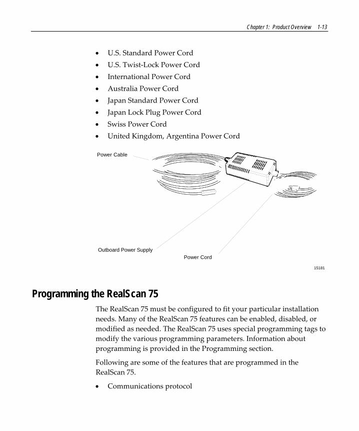
Power Supply The RealScan 75 uses an external power supply to provide DC voltage to the unit. The power supply can be located on the checkstand floor or mounted to the checkstand wall. It is a universal 30‐Watt power supply that accepts an input line voltage of 90 to 260 Vac at a frequency of 47 to 63 Hz. Included is a standard 10‐foot replaceable line cord and a low voltage power cable that connects the power supply to the RealScan 75.
Following is a list of the available line cords.
Chapter 1: Product Overview 1-13
• U.S. Standard Power Cord • U.S. Twist‐Lock Power Cord • International Power Cord • Australia Power Cord • Japan Standard Power Cord • Japan Lock Plug Power Cord • Swiss Power Cord • United Kingdom, Argentina Power Cord
Power Cable
Power CordOutboard Power Supply
15181
Programming the RealScan 75 The RealScan 75 must be configured to fit your particular installation needs. Many of the RealScan 75 features can be enabled, disabled, or modified as needed. The RealScan 75 uses special programming tags to modify the various programming parameters. Information about programming is provided in the Programming section.
Following are some of the features that are programmed in the RealScan 75.
• Communications protocol

1-14 Chapter 1: Product Overview
• Good Read tone • Not On File Tone volume • Timers • Bar code types • Add‐On code • Label Identifiers • RS‐232 requirements • Scale parameters • PACESETTER functions • Specific competitive host terminal requirements
GS1 DataBar GS1 DataBar, formerly Reduced Space Symbology (RSS), bar codes permit more data to be recorded in a smaller physical space. This is accomplished by encoding the data in large symbol characters rather than encoding each data character separately. Also, no quiet zone is required around the symbols. The RealScan 75 with GS1 DataBar can read four types of GS1 DataBar bar codes.
GS1 DataBar-14 GS1 DataBar‐14 is a linear symbology that encodes 14 UCC/EAN digits. This structure provides four segments that can be decoded separately, then reconstructed. The total symbol contains 96 modules combined into 46 elements (bars and spaces).
19254
0100012345678905

Chapter 1: Product Overview 1-15
GS1 DataBar-14 Stacked GS1 DataBar‐14 Stacked is a 2‐row format. The bottom row is higher that the top row and the two are separated with a separator pattern. The stacked format is used when not enough linear space is available. An example use is marking produce in a grocery store.
19255
0100991234567899
GS1 DataBar Expanded GS1 DataBar Expanded is a variable length linear symbology. It can encode 74 numeric or 41 alpha characters. GS1 DataBar Expanded can be scanned and decoded in up to 22 segments and then reconstructed.
19256
9987 6543 2101 2345 6789 8888 8
GS1 DataBar Expanded Stacked GS1 DataBar Expanded Stacked is similar too GS1 DataBar‐14 Stacked except it uses the GS1 DataBar Expanded format for creating the symbol
192570192 1234 5698 7457 3202 0000 9939 0200 296
1-16 Chapter 1: Product Overview
Refer to Special Programming in Chapter 6: Programming for information about enabling GS1 DataBar.
Scan Doctor Scan Doctor is the state‐of‐the‐art diagnostic software included in every RealScan 75. It monitors the unit to identify components that may not be functioning correctly. It also provides inquiry capability for the host terminal to access specific diagnostic data. Scan Doctor diagnoses the RealScan 75 each time power is applied and continually during operation. When a problem is found, it notifies the operator through speech synthesis, or beeps and a flashing Status Indicator if voice is turned off. Scan Doctor does not check any Bizerba scale components in the RealScan 75‐4005.
Power-On Wellness Check When power is applied to the RealScan 75, the Scan Doctor checks many of the scanner and scale components: RAM, ROM, EEPROM, Spinner Motor, Interface Board, Laser Diode, ASIC, and scale hardware. If Scan Doctor finds a problem that can hinder operation of the RealScan 75, it disables the unit, otherwise the problem is identified and operation continues.
Ongoing Wellness Check Scan Doctor is at work all the time that the RealScan 75 is turned on. It constantly monitors RAM, the Spinner Motor, the Laser Diode, and scale hardware.
Service Diagnostics Scan Doctor includes service diagnostics for the trained service technician. These go beyond the wellness checks and are accessed through the use of special programming tags.
Chapter 1: Product Overview 1-17
Servicing the RealScan 75 The RealScan 75 can be serviced without removing it from the checkstand. Most components can be replaced while the scanner is still in the checkstand provided the proper service clearances are maintained. Refer to Site Requirements for service clearance information. The RealScan 75 must; however, be removed from the checkstand to replace the following boards.
• Interface board • RS‐232 dual peripheral ports board Note: If you remove a RealScan 75‐2xxx/8xxx from the checkstand to service it, you must calibrate the scale after you install the RealScan 75 back into the checkstand.
Soft Power Down/Power Up The RealScan 75 senses periods of scanner inactivity. The scannerʹs soft power down feature extends the life of the RealScan 75 by disabling major portions of the unit, including the laser diode, spinner motor, and associated electronics. The length of the inactive period prior to the soft power down is user‐selected and programmed through tags.
Scanner power up occurs when the RealScan 75 motion detector detects movement. This detector is located on the operator display panel, to the left of the vertical scan window. The operator can also power up the unit by pressing the Scale Zero button on the operator display panel (RealScan 75‐2xxx/8xxx only). The RealScan 75 can also be powered up when the checker signs on the host terminal. This capability assumes appropriate host terminal software.
1-18 Chapter 1: Product Overview
Voice Messages If your RealScan 75 has voice enabled, you are alerted to certain mode changes and error conditions by synthesized voice messages. These messages give either the changed mode or the error message with its suggested corrective action. Voice is enabled and disabled through voice message programming.
Note: Voice can be disabled by pressing the Scale Zero button while a voice message is being given.
The scanner/scale provides audible voice messages during the following events:
• When the scanner/scale goes online or offline • When you check the communications protocol • When you test item tags using PACESETTER Plus • When certain error conditions occur • When there is interference with the scale • When the scanner windows become dirty
Volume Adjust Button The RealScan 75 has a Volume Adjust button located on the Operator Display Panel. An icon of a speaker emitting sound waves identifies the Volume Adjust button. The purpose of the volume Adjust button is to allow the operator to change the scannerʹs Good Read tone volume to a comfortable level depending on the ambient noise level at the time. Depending on how the RealScan 75 is programmed, it can have either six or eleven different volume settings. The Volume Adjust button can also be use to change the frequency (tone) of the Good Read tone. This feature must be enabled through programming.
Note: Permanent changes to tone volume require changing the RealScan 75 program.

Chapter 1: Product Overview 1-19
Window Maintenance Indicator The RealScan 75 has a Window Maintenance indicator located on the operator display panel. An icon of a hand moving a towel in a wiping motion identifies the Window Maintenance indicator. When the dirty window indicator (yellow light) is ON, it indicates that the Scan Window (normally the Top Plate window), has become dirty and need to be cleaned for optimum scanner performance. It is also occasionally necessary to clean the window located under the Top Plate to remove loose debris or dust. The Window Maintenance indicator light may also come on if the glass has excessive scratches.

1-20 Chapter 1: Product Overview
Interface Cables The RealScan 75 Scanner/Scale can be connected to many different host terminals. It can connect to all NCR Retail Terminals as well as many competitive terminals. This requires many different interface cables.
Note: RealScan 75 Super ASIC models do not have OCIA or dual cable communications. Configurations that require this must use an older RealScan 75 Single ASIC model.
Host Terminals
NCR Host Terminals Host Terminal Interface Cable Corporate ID Part Number Length
2123 OCIA Dual-Cable Scanner 2123-K316 230-0113973Dual-Cable Scale 2123-K316 230-0113973
2126 OCIA Dual-Cable Scale 1416-C015-0040 497-0300371 4 meters (13.1 feet)Dual-Cable Scale 1416-C015-0080 497-0300372 8 meters (26.2 feet)Dual-Cable Scale 1416-C013-0040 497-0300350 4 meters (13.1 feet)
1416-C013-0080 497-0300351 8 meters (26.2 feet)Dual-Cable Scale2154, 2155, OCIA2156, 21572552 OCIA Dual-Cable Scale 1416-C028-0040 497-0300543 4 meters (13.1 feet)
1416-C028-0080 497-0300544 8 meters (26.2 feet)Dual-Cable Scale2557 OCIA Dual-Cable Scale 1416-C027-0040 497-0300533 4 meters (13.1 feet)
1416-C027-0080 497-0300534 8 meters (26.2 feet)Dual-Cable Scale
Dual-Cable Scale 1416-C013-0040 497-0300350 4 meters (13.1 feet)1416-C013-0080 497-0300351 8 meters (26.2 feet)Dual-Cable Scale
7050, 7051 OCIA
Dual-Cable Scale 1416-C061-0040 497-0301144 4 meters (13.1 feet)7052, 7053, 7054 OCIADual-Cable Scale 1416-C013-0040 497-0300350 4 meters (13.1 feet)
1416-C013-0080 497-0300351 8 meters (26.2 feet)Dual-Cable Scale7070 OCIA
Dual-Cable Scale 1416-C061-0040 497-0301144 4 meters (13.1 feet)2760 OCIA
1255 OCIA Dual-Cable Scale 1416-C027-0040 497-0300533 4 meters (13.1 feet)1416-C027-0080 497-0300534 8 meters (26.2 feet)Dual-Cable Scale
7452, 7453 RS-232 Single-Cable 1416-C019-0040 497-0300422 4 meters (13.1 feet)Single-Cable 1416-C019-0080 497-0300423 8 meters (26.2 feet)
16232
7450 OCIA Dual-Cable Scale 1416-C061-0040 497-0301144 4 meters (13.1 feet)
7445 RS-232 Single-Cable 1416-C019-0040 497-0300422 4 meters (13.1 feet)Single-Cable 1416-C019-0080 497-0300423 8 meters (26.2 feet)
5932 RS-232 Scanner Only 1416-C239-0040 497-0407723 4 meters (13.1 feet)

Chapter 1: Product Overview 1-21
Casio Host Terminals Host Terminal Interface Cable Corporate ID Part Number
2100 OCIA
Length
16218
Dual-Cable ScannerDual-Cable Scale
1416-C072-0040 497-0301403 4 meters (13.1 feet)1416-C073-0040 497-03014044-Bit Parallel 4 meters (13.1 feet)
Datachecker Host Terminals Host Terminal Interface Cable Corporate ID Part Number
MDL/Datachecker
Length
16351
Single-Cable
1416-C062-0040 497-0301152
4 meters (13.1 feet)
T 2001
1416-C144-0040 497-0301889
4 meters (13.1 feet)
2200
Single-CableMDL/DatacheckerMDL/Datachecker Single-Cable 8 meters (26.2 feet)1416-C144-0080 497-0301890
Epson Host Terminals Host Terminal Interface Cable Corporate ID Part Number
Epson PC RS-232
Length
16354
Single-Cable 4 meters (13.1 feet)1416-C357-0040 497-0408212
Fujitsu Host Terminals Host Terminal Interface Cable Corporate ID Part Number
Fujitsu 8774 RS-232
Length
19317
Single-Cable 4 meters (13.1 feet)1416-C560-0040 497-0416457
Gilbarco Host Terminals Host Terminal Interface Cable Corporate ID Part Number
TCR-15 RS-232
Length
16219
Scanner Only 1416-C237-0040 497-0303139 4 meters (13.1 feet)

1-22 Chapter 1: Product Overview
IBM Host Terminals Host Terminal Interface Cable Corporate ID Part Number
4683, 4684 IBM 4683 Port 17
Length
16220
Single-Cable 1416-C020-0040 497-0300402 4 meters (13.1 feet)1416-C020-0080 497-0300403 8 meters (26.2 feet)
4682, 4683, IBM Port 9B 1416-C070-0040 497-0301390 4 meters (13.1 feet)1416-C070-0080 497-0301391 8 meters (26.2 feet)4684, 4693
4683, 4684 OCIA Port 5B 1416-C142-0040 497-0301751 4 meters (13.1 feet)4694 IBM Port 9E 1416-C070-0040 497-0301390 4 meters (13.1 feet)
1416-C070-0080 497-0301391 8 meters (26.2 feet)PC RS-232 9-PIn 1416-C019-0040 497-0300422 4 meters (13.1 feet)
1416-C019-0080 497-0300423 8 meters (26.2 feet)
Single-CableSingle-CableSingle-CableSingle-CableSingle-CableSingle-CableSingle-CableSingle-Cable
ICL Host Terminals Host Terminal Interface Cable Corporate ID Part Number
OCIA
Length
16221
Scanner Only 1416-C264-0040 497-0404882 4 meters (13.1 feet)1416-C264-0080 497-0404883 8 meters (26.2 feet)Scanner Only
9518-01/21/61/62/71
Dual-Cable Scanner 1416-C264-0040 497-0404882 4 meters (13.1 feet)1416-C264-0080 497-0404883 8 meters (26.2 feet)Dual-Cable Scanner
Dual-Cable Scale 1416-C265-0040 497-0404918 4 meters (13.1 feet)1416-C265-0080 497-0404919 8 meters (26.2 feet)Dual-Cable Scale
9518-200 RS-232 Dual-Cable Scanner 1416-C140-0040 497-0301711 4 meters (13.1 feet)Dual-Cable Scale 1416-C146-0040 497-0301931 4 meters (13.1 feet)25-Pin D Shell
RS-232 Dual-Cable Scanner 1416-C227-0040 497-0301031 4 meters (13.1 feet)Dual-Cable Scale 1416-C226-0040 497-0302021 4 meters (13.1 feet)9-Pin D Shell
RS-232
Team POS 5000 RS-232 Single-Cable 1416-C019-0040 497-0300422 4 meters (13.1 feet)Single-Cable 1416-C019-0080 497-0300423 8 meters (26.2 feet)
MDL/Datachecker Single-Cable
1416-C260-0040 497-0404766
4 meters (13.1 feet)
1416-C260-0080 497-0404767
8 meters (26.2 feet)9520-150 MDL MDL 9-Pin
1416-C144-0040 497-0301889
4 meters (13.1 feet)8 meters (26.2 feet)
9520/RS-232
Single-Cable 1416-C144-0080 497-03018909520-150 MDL
Single-CableSingle-Cable
Microbilt Host Terminals Host Terminal Interface Cable Corporate ID Part Number
8010 RS-232 6-Pin
Length
16222
Scanner Only 1416-C326-0040 497-0407181 4 meters (13.1 feet)

Chapter 1: Product Overview 1-23
NEC Host Terminals Host Terminal Interface Cable Corporate ID Part Number
NEC Terminal RS-232
Length
16352
Scanner Only 4 meters (13.1 feet)1416-C274-0040 497-0405139
SASI Host Terminals Host Terminal Interface Cable Corporate ID Part Number
1028 RS-232
Length
16353
Dual-Cable Scanner
1416-C341-0040 497-0407543
4 meters (13.1 feet)
Dual-Cable Scannerex-10Dual-Cable Scale
1416-C342-0040 497-0407544
4 meters (13.1 feet)1416-C343-0040 497-0407545
Dual-Cable Scaleex-10 RXD Enable RS-232 4 meters (13.1 feet)
4 meters (13.1 feet)
1416-C343-0040RS-232
497-0407545 4 meters (13.1 feet)
4 meters (13.1 feet)1416-C343-0040 497-0407545Dual-Cable ScannerDual-Cable Scale
1416-C377-0040 497-0409575
Siemens Nixdorf Host Terminals Host Terminal Interface Cable Corporate ID Part Number
Beetle RS-232
Length
16223
Scanner Only 1416-C263-0040 497-0408081 4 meters (13.1 feet)
TEC Host Terminals Host Terminal Interface Cable Corporate ID Part Number Length
16224
ST-5500 RS-232 Single-Cable 1416-C019-0040 497-0300422 4 meters (13.1 feet)Single-Cable 1416-C019-0080 497-0300423 8 meters (26.2 feet)
Verifone Host Terminals Host Terminal Interface Cable Corporate ID Part Number
Ruby Verifone RS-232
Length
16225
Scanner Only 1416-C254-0040 497-0404530 4 meters (13.1 feet)

1-24 Chapter 1: Product Overview
Wayne Host Terminals Host Terminal Interface Cable Corporate ID Part Number
Wayne Controller RS-232 9-Pin
Length
16226
Scanner Only 1416-C236-0040 497-0403138 4 meters (13.1 feet)
Wedge Host Terminals Host Terminal Interface Cable Corporate ID Part Number
Wedge RS-232 6-Pin
Length
16227
Scanner Only 1416-C141-0040 497-0301721 4 meters (13.1 feet)

Chapter 2: Site Requirements
The NCR customer is responsible for preparing the site for installation of the NCR RealScanRealScan 75. Information is provided to help with this task.
16389
AB
CCDD
Customer Responsibilities The customer must do or provide the following.
• When required by NCR, provide the NCR Customer Services Representative with appropriate drawings that indicate the following. Location of equipment. Site wiring (power and signal, paths, and lengths). Location of other equipment capable of generating large
amounts of electrical noise, electromagnetic interference, heat, and so on.
2

2-2 Chapter 2: Site Requirements
• Provide floor coverings and environmental systems that prevent static electricity build‐up and discharge.
• Provide and install necessary power distribution boxes, conduits, grounds, lightning arrestors, and associated hardware.
• Make sure clear space and environmental requirements of the unit are met.
• Make all building alterations necessary to meet wiring and other site requirements.
• Make sure all applicable codes, regulations, and laws (including, but not limited to, electrical, building, safety, and health) are met.
• Provide and install all communication cables, wall jacks, special connectors, and associated hardware.
• Provide and install auxiliary power or other equipment as required.
Environment Considerations The RealScan 75 operates in most standard working environments. Temperature ranges permitted are greater when the RealScan 75 is in storage or transit. There is also an extreme environmental range in which the RealScan 75 can operate for a short time without suffering damage. However, this extreme operating range can last for only one hour. The following table gives the various environmental requirements.

Chapter 2: Site Requirements 2-3
16375
Normal Operating Extreme Operating Storage TransitTemperature
TemperatureChangeRelativeHumidityBarometricPressureAmbientLight
AcousticalNoiseVibrationAndShock
10°C to 40°C -15°C to 45°C -15°C to 50°C -40°C to 60°C50°F to 104°F 5°F to 113°F 5°F to 120°F -40°F to 140°F10°C per hour 20°C per hour 20°C per hour 20°C per hour18°F per hour 36°F per hour 36°F per hour 36°F per hour5% to 95%Non-condensing
5% to 95%Non-condensing
5% to 95%Non-condensing
5% to 95%Non-condensing
105 x 10³ Pa to79.5 x 10³ Pa
105 x 10³ Pa to79.5 x 10³ Pa
105 x 10³ Pa to79.5 x 10³ Pa
200 Foot-candlesmax (2152 Lux)on both scannerWindows
200 Foot-candlesmax (2152 Lux)on both scannerWindows
55 dBa or less 55 dBa or less
1 to 10 Hz with adouble amplitudeof 0.127 cm(0.05 in.);10 to 300 Hz witha maximum of0.25 g
1 to 10 Hz with adouble amplitudeof 0.127 cm(0.05 in.);10 to 300 Hz witha maximum of0.25 g
Installation Location Your RealScan 75 mounts in a cutout in a checkstand. If you are replacing a RealScan 20 or RealScan 24 with a RealScan 75, you do not need to change the size of the hole if it was cut to the specified dimensions. The counter top should be level since the RealScan 75 should be level to scan efficiently. You must consider the length of the various cables and how to route them to the RealScan 75. You must also consider service slack in the cables to permit lifting the RealScan 75 out of the checkstand without disconnecting the cables.
FOR EFFICIENT SCANNING When cutting the checkstand hole, be careful to maintain the specified dimensions. The scanner/scale should be level on either (2) rails, 1 front and 1 rear, or (4) points of contact, for example (4) bolts.

2-4 Chapter 2: Site Requirements
Note: The four adjustable support posts on the Scale Support Bar Assembly are set at the factory. Do not attempt to adjust the Top Plate using these posts. Adjust the checkstand supports to align the Top Plate with the checkstand.
For proper scale operation, a horizontal clearance between the leading and trailing edges of the top plate and the checkstand must be maintained. NCR recommends that an adjustable plate be placed between the leading edge of the RealScan 76 and the belt on the checkstand. Note: The depth dimensions provided on the following pages are from the bottom of the scanner to the highest plane on the top plate.

Chapter 2: Site Requirements 2-5
Checkstand Cutout—RealScan 75-1xxx/2xxx
14956
G
F
A
C C
B
D D
E
H
I
A
B
E
C
C
D
A B C D E7875-1xxxScanner
7875-2xxxScanner/Scale
7875-1xxxScanner
7875-2xxxScanner/Scale
F G H I Note: Dimension A for an NCR 7875-2xxxincludes a spacer along each side of the unit so that it fits an existing NCR 7870-2xxx cutout.
Recommended shelf to catchthe NCR 7875 if dropped during installation.
*
F
12 1/16 in. 20 1/16 in. 1 3/8 in. 1/2 in. 17 5/16 in.30.63 cm 50.95 cm 3.49 cm 1.27 cm 43.97 cm11 5/8 in. 20 1/16 in. 1 3/8 in. 3/8 in. 17 5/16 in.29.51 cm 50.95 cm 3.49 cm 0.95 cm 43.97 cm
>= 1 in. 5 1/8 in. 7 in. 7 1/4 in.>= 2.54 cm 13.0 cm 17.78 cm 18.42 cm>= 1 in. 5 1/8 in. 7 1/8 in. 7 1/4 in.>= 2.54 cm 13.0 cm 18.10 cm 18.42 cm

2-6 Chapter 2: Site Requirements
Checkstand Cutout—RealScan 75-7xxx/8xxx
20551
GD D
H
I
A
B
E
J
C
D
Recommended shelf to catchRealScan 7875 if dropped during installation.
*
C J
B
EF
A
F*
A B C D E11.63 in.29.51 cm
20.06 in.50.96 cm
1.38 in.3.49 cm
0.38 in.0.95 cm
17.63 in.44.77 cm
7875-72xxScanner
12.06 in.30.63 cm
20.06 in.50.96 cm
1.38 in.3.49 cm
0.50 in.1.27 cm
17.63 in.44.77 cm
7875-82xxScanner/Scale
7875-72xxScanner
7875-82xxScanner/Scale
F G>= 1.38 in.>= 3.49 cm
7.13 in.18.10 cm
>= 1.38 in.>= 3.49 cm
7.13 in.18.10 cm
H I7.25 in.
18.42 cm7.75 in.
19.69 cm
7.13 in.18.10 cm7.38 in.
18.73 cm
J1.06 in.2.70 cm1.06 in.
2.70 cm
Note:Dimension A for a 7875-82xx includes a spacer along each side of the unit so that it fits an existing 7870-2xxx cutout. If the spacers are not used, the dimension is 11 5/8 in. (29.51 cm).
Note:Dimensions H and I include a Produce Guard for the 7875-82xx.

Chapter 2: Site Requirements 2-7
Checkstand Cutout—RealScan 75-3xxx
23377
F
A
D
G
A
BC
D
A B C D E
Note:
11 5/8 in. 16 1/8 in. 3/8 in. 14 17/25 in.1 3/8 in.29.51 cm 40.96 cm 0.95 cm 37.28 cm3.49 cm
F G H
4 15/16 in. 7 1/8 in. 7 1/4 in.12.54 cm 18.10 cm 18.42 cm
The RealScan 7875-3xxx MUST sit on a shelf below the checkstand surface.Also, the shelf should be open at the front and back.
C
E
B
H

2-8 Chapter 2: Site Requirements
Checkstand Cutout—RealScan 75-4xxx
G
F
C
B
D
E
A B C D
E
29.21 cm 43.94 cm 18.10 cm 18.42 cm
12.93 cm
11.5 in. 17 5/16 in 7 1/8 in. 7 1/4 in.
5 1/16 in.
G H
44.26 13.0 cm
17 7/16 in. 5 1/8 in.
F29.51 cm11 5/8 in.
A
F
H
19306

Chapter 2: Site Requirements 2-9
RealScan 25 Remote Compact Display Dimensions Following are the dimensions of the RealScan 25 Remote Compact Display. The holes are spaced to align with those of the older RealScan 25 Remote Post Display and with some competitor models.
24173
E
F
G
H
C
I
J
K
AB
D
A115.31 mm
B C D E
F
93.98 mm 3.96 mm 7.62 mm 84.83 mm4.54 in 3.70 in 0.156 in 0.30 in 3.34 in
G H I J K11.17 mm 16.25 mm 41.65 mm 266.19 mm 104.39 mm 314.96 mm
0.44 in 0.64 in 1.64 in 10.48in 4.11 in 12.4 in
Note: Dimension I is also the height of a single-display unit.
BASE

2-10 Chapter 2: Site Requirements
Hole Requirements For Cables When you run the various cables through the checkstand, you might have to drill holes in some of the panels. The holes must be large enough for the connector on one end of the cable to pass through. You must also ensure that there are no sharp edges to cut the cable. The following table gives the minimum hole size for each of the RealScan 75 cables.
16376
Cable Cable Length Minimum Hole SizePower Cord - Outlet to Power Supply 3.05 meters (10 feet) 3.18 centimeters (1.25 inches)Power Cable - Power Supply to RealScan 75 1.22 meters (4 feet) 1.52 centimeters (0.50 inch)
Interface Cable 8.00 meters (26.24 feet)4.00 meters (13.12 feet)
Remote Display Cable
1.90 centimeters (0.75 inch)
8.00 meters (26.24 feet)4.00 meters (13.12 feet)
1.90 centimeters (0.75 inch)1.90 centimeters (0.75 inch)
1.90 centimeters (0.75 inch)
Ventilation Requirements The RealScan 75 is designed to operate without an exhaust fan in the checkstand. However, there must be adequate convection air flow, and no other equipment can be in the checkstand that causes the ambient temperature inside the checkstand to be outside the following ranges.
• Maximum ambient temperature inside the checkstand – 40°C (104°F).
• Maximum variation between ambient temperature inside and outside the checkstand – 7°C (12.6°F).
For example, if the ambient temperature outside the checkstand is 24.4 °C (76 F), the ambient temperature inside the checkstand cannot be greater than 31.4 C (88.6 F).
If the checkstand contains other heat producing equipment, you may need to use forced air to keep the temperature within the specified range. However, air coming into or leaving the checkstand MUST NOT enter or exit past the RealScan 75.

Chapter 2: Site Requirements 2-11
Physical Characteristics The RealScan 75 is a single device that sits in a hole cut into the checkstand. The power supply mounts in a remote location. Connect the RealScan 75 to the host terminal with one or two cables, depending on the configuration of the terminal. If the RealScan 75 has a scale, it can have a display mounted on the top of the unit, or it can use a remote display mounted elsewhere in the checkout area.
Weight The weight of the RealScan 75 varies depending on the model. Following are the installed weights of the basic models.
16377
Model Kilograms Pounds7875-1xxx - Full Size - Scanner Only
11.41 24.97
7875-2xxx - Full Size - Scanner/Scale11.50 25.16
14.6713.87
32.1030.35
7875-10xx
ASIC
Single / Dual ASIC7875-12xx Super ASIC
7875-20xx Single / Dual ASIC7875-22xx Super ASIC
7875-3xxx - Compact Size - Scanner Only10.8710.95
23.7723.96
7875-30xx Single / Dual ASIC7875-32xx Super ASIC
7875-7xxx17.9313.25
39.2328.98
7875-70xx W/ EAS Single / Dual ASIC7875-70xx W/O EAS Single / Dual ASIC
7875-8xxx - Deep Bucket - Scanner/Scale21.1516.46
46.2636.01
7875-80xx W/ EAS Single / Dual ASIC7875-80xx W/O EAS Single / Dual ASIC
- Deep Bucket - Scanner Only

2-12 Chapter 2: Site Requirements
Display Clearance If the RealScan 75 contains an integrated display, you must provide clearance for viewing the display. The figure shows the display clearance. The display must be visible to both the customer and the operator according to Weights and Measures requirements. If checkstand design restricts viewing, the RealScan 25 Remote Display may be required to satisfy the visibility requirements.
30
This area must be clearfor viewing optionalintegrated display. 60
5060
14954

Chapter 2: Site Requirements 2-13
Service Clearance You can service most components of the RealScan 75 without removing the unit from the checkstand. This includes scale calibration and installation of the Weights and Measures seal. However, you must provide clearance around the RealScan 75 for servicing. Clearance is also required for cleaning the unit. The following illustration shows the required service clearances.
A A
C
BItem Flow Area
All Installations Installations Without An Integrated Display
14955
A = 20.3 cm (8.0 in.) minimum if checkstand structure is not removable for servicing.2.5 cm (1.0 in.) minimum if checkstand structure is removable for servicing.
B = 35.6 cm (14.0 in.) minimum if checkstand structure is not removable for servicing.17.8 cm (7.0 in.) minimum if checkstand structure is removable for servicing.
C = 13.0 cm (5.1 in.) minimum clearance to closest checkstand panel.The NCR 7875-1xxx/2xxx/4005 must not be supported by a bottom panel.
Note: RealScan 7875-80xx units with a Produce Guard must have enough clearance to removethe Produce Guard for cleaning. The dimensions given here satisfy these requirements.
Mounting surface for keyboard must be removable for the following.• Servicing the unit.• Removing the 7875-80xx Produce Guard.• Replacing the vertical window.

2-14 Chapter 2: Site Requirements
Preparing the Site This document contains information necessary for the preparation of a site conforming to NCR specifications. It is important that the site complies with the requirements specified in this document because, once the equipment has been installed, deficiencies in site preparation or the problems caused by these deficiencies are much more difficult to detect or correct. Further, failure to comply with these requirements or to take proper steps to protect equipment against risks identified in this document may cause serious damage to the equipment and to the customerʹs business.
In addition to the need to comply with the requirements specified, electrical wiring and mechanical systems must also comply with all relevant codes, laws, and regulations. It is important that a customer or a customer agent who is fully conversant with the special requirements of electronic equipment prepare the site. The responsibility of ensuring that the site is prepared in compliance with this document remains with the customer.
For information and guidance proposes only, a list of Customer Responsibilities is provided, in general terms, of those matters for which the customer is responsible. This list is not intended to be comprehensive, and in no way modifies, alters, or limits the responsibility of the customer for all aspects of adequate site preparation.
NCR staff is available to answer questions relating to the contents of this document, but except where:
• The customer has been notified that a full or partial consulting service is available and/or that NCR is willing to undertake a preliminary or final site survey and
• The customer shall have entered into a formal contract with NCR for provision of the same.

Chapter 2: Site Requirements 2-15
No comment, suggestion, or advice offered or not offered about preparation of the site nor any inspection of the site whether before or after preparation is to be taken as approval of the location of the site and equipment or of its preparation, and NCR is not liable in respect of any comment, suggestion or advice given by its staff or in respect of any failure to give advice.
Finally, only the customer can know the full extent of damage that may be caused to his business by reason of failure of the equipment that is to be installed. For this reason it is the customerʹs responsibility to ascertain the extent of any such possible damage to his existing or planned business, and to effect full insurance in respect of it.
Power Considerations The RealScan 75 receives power from an external power supply. The power supply is mounted in a remote location close to the RealScan 75. The power supply is a 43‐watt switching power supply with the following inputs.
• Voltage – 90 to 260 Vac • Frequency – 47 to 63 Hz • Input Power – 55 Watts
Power Application The RealScan 75 has no on/off switch in the unit. Therefore, you must wire the checkstand to include a recessed, 15A circuit breaker accessible to the operator. This circuit breaker serves as the on/off switch. It is also needed to reset the unit during programming and to remove power from the unit during servicing.

2-16 Chapter 2: Site Requirements
Checkstand Wiring
Feeder wiring and insulated ground frommain service panel to distribution panelto be run in metal conduit.
The electrical wiring must meet allelectrical codes, laws, and regulations.
Note:
Circuit Breakers
NCR circuits should be run inseparate metal Conduits.
Isolated/InsulatedGround Bus
Isolated Ground Receptacles
Neutral andGround Bus
NeutralBus
InputVoltage
Input Voltage L1, L2 Circuit BreakersU.S., Canada, &Japan
European
International
100Vac to 120Vac
220Vac
220Vac to 240Vac
100Vac to 120Vac
220Vac
220Vac to 240Vac
Standard single-pole; valuedetermined by type of devicebranch and by electrical code.
European double-pole.
Circuit B: Terminal
Installation Type
NCR circuits must be dedicated toNCR equipment or other logicallyconnected electronic equipment(modems, DAA, bridges, etc.)
Note:
Circuit C: Scanner/ScaleReceptacle should be easilyaccessible and near theScanner/Scale
L2
L3
Distribution Panel
Main ServicePanel
Conduit
CheckstandFrame
Circuit A: Checkstand
BeltMotor
Belt ControlLighting
Misc. Equip.N
G
L1
R0121

Chapter 2: Site Requirements 2-17
Power Transient Protection Voltage transients, surges, sags, impulses, and spikes may be experienced routinely or sporadically. When such phenomena occur, the use of protective devices may be required to ensure proper operation of the equipment.

Chapter 3: Installing Information
Installing the RealScan 75 consists of four main steps. Sometimes other information is required depending of the installation. Enabling special functions is described in Chapter 6: Programming.
3

3-2 Chapter 3: Installing Information
Step 1–Verify That Unit Is Ready To Install
Reporting a Damaged RealScan 75 When you receive the NCR RealScan 75, inspect the shipping carton for damage. If the scanner/scale has been damaged due to shipping, notify the carrier, your NCR representative, or your supplier if the unit was not purchased directly from NCR.
What is in the Box After you unpack the RealScan 75 according to the instructions printed on the box, take inventory to ensure that you have received all components. The following list identifies the package contents.
• NCR RealScan 75 • Power Supply • Power Cord • Top Plate • Documentation • Interface Cable (when cable feature is requested with order) • Power Cord Documents (International Units) • Metal Foil Stamping Plate (200x Model International Units)
Cable Verification The RealScan 75 can be used with many different host terminals. Verify that you have received the correct interface cable (some installations require two interface cables). A list of available interface cables is provided in Interface Cables in the Product Information topic. Also, be sure you have the correct power cord.

Chapter 3: Installing Information 3-3
Checkstand Verification Verify that the checkstand is prepared according to the following.
• Checkstand cutout is correct size. • Display and service clearances are adequate. • Checkstand is properly wired. • Power cord is correct power cord for the electrical outlet.

3-4 Chapter 3: Installing Information
Step 2–Install the Unit Note: Before attempting to install the RealScan 75, you must prepare your site in accordance with the requirements described in Site Requirements.
Note: The RealScan 75 is fully assembled at the factory and requires no operator assembly. The laser module is an integral part of the factory assembled device and does not have any controls that can increase the level of laser light or collateral radiation from the RealScan 75.
To install the NCR RealScan 75 in the checkstand, first install all the cables.
1. Verify that the RealScan 75 power receptacle switch is off. Plug the power cord into the RealScan 75 power receptacle. Pass the power cable from the power supply through the checkstand opening.
2. Connect the communications interface cables to the host terminal. Refer to the terminal documentation for instructions on how to connect the interface cables.
Note: Some terminals may require a trained service technician to open the terminal and connect the interface cables.
3. Pass the interface cables through the checkstand opening.
4. If you are connecting a remote display, pass the remote display cable through the checkstand opening.
5. If you are connecting an RS‐232 peripheral device, pass its interface cable through the checkstand opening.
6. Place the unit so a portion of the tower end is directly over the hole in the checkstand (on the customer side).
Note: Refer to Appendix A: Cable Configuration on how to connect cables. See also Appendix B: Connect the Peripheral Devices.

Chapter 3: Installing Information 3-5
Complete the Installation Turn on the AC Power by turning on the circuit breaker.
RealScan 75-2xxx/8xxx Units The RealScan 75‐2xxx/8xxx units contain a scale that must be set for the correct AC voltage frequency and also must be calibrated before the unit is operational.
Calibrate the scale by going to Step 3.
RealScan 75-1xxx/3xxx/7xxx Units Go to Step 4. The RealScan 75‐1xxx/3xxx/7xxx units are scanner only; there is no scale to calibrate.
RealScan 75-4xxx Units Go to Step 4. The RealScan 75‐4xxx is a scanner that is price computing scale ready. If the unit contains a Bizerba Computing scale, do not attempt to calibrate the scale, this scale is calibrated at the factory.
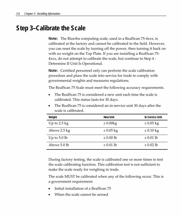
3-6 Chapter 3: Installing Information
Step 3–Calibrate the Scale Note: The Bizerba computing scale, used in a RealScan 75‐4xxx, is calibrated at the factory and cannot be calibrated in the field. However, you can reset the scale by turning off the power, then turning it back on with no weight on the Top Plate. If you are installing a RealScan 75‐4xxx, do not attempt to calibrate the scale, but continue to Step 4 ‐ Determine If Unit Is Operational.
Note: Certified personnel only can perform the scale calibration procedure and place the scale into service for trade to comply with governmental weights and measures regulations.
The RealScan 75 Scale must meet the following accuracy requirements.
• The RealScan 75 is considered a new unit each time the scale is calibrated. This status lasts for 30 days.
• The RealScan 75 is considered an in‐service unit 30 days after the scale is calibrated.
Weight New Unit In Service Unit
Up to 2.5 kg ± 0.00kg ± 0.05 kg
Above 2.5 kg ± 0.05 kg ± 0.10 kg
Up to 5.0 lb ± 0.00 lb ± 0.01 lb
Above 5.0 lb ± 0.01 lb ± 0.02 lb
During factory testing, the scale is calibrated one or more times to test the scale calibrating function. This calibration test is not sufficient to make the scale ready for weighing in trade.
The scale MUST be calibrated when any of the following occur. This is a government requirement.
• Initial installation of a RealScan 75 • When the scale cannot be zeroed

Chapter 3: Installing Information 3-7
• When the diagnostics indicate a calibration error • When the load cell or scale board have been replaced (Single &
Dual ASIC models) • When the load cell or digital board have been replaced (Super ASIC
models) Note: The RealScan 75‐2xxx may not have a RealScan 25 Remote Display when connected to some host terminals. If this is the case, a Field Service Calibration Display (NCR part number 250‐0029750) is required unless the RealScan 75 has voice enabled. Calibration information is NOT sent to the host terminal. Contact a NCR representative about calibrating the scale.
Note: NCR RealScan 25 Remote Compact Display does not display the “Scale Ready.”
The calibration procedure sets the load cell and the electronics to interpret the weight of an item accurately. The scale can be calibrated after power has been supplied for 30 minutes if the ambient air condition has been 20° C (68° F) or above for at least 24 hours. If the ambient air condition has not been met (that is, below 20° C (68° F)), then the scale must be on for at least 6 hours before it can be calibrated. One or more certified weight sets are required to calibrate and certify the scale.
• Whole Pound Weight Set: NCR Part Number 998‐0633009 • Fractional Pound Weight Set: NCR Part Number 998‐0633012 • Kilogram Weight Set: Obtain locally The RealScan 75 maintains an audit trail of scale calibration and weighs parameter setting. The audit trail consists of two event counters. Display the audit trail count by pressing and holding the Scale Zero button on the Operator Display Panel. The display alternates between Cal xxx and PAr xxx. The Cal value is the number of times the scale has been calibrated. The PAr value is associated with the weigh parameter setting and should never change.

3-8 Chapter 3: Installing Information
Note: The audit trail can be displayed only on units with the RealScan 25 Remote Display.
Note: Some host terminals can corrupt the calibration settings if they are connected during scale calibration. Therefore, NCR recommends disconnecting the interface cable before starting calibration of the scale and then reconnect it after completing the calibration procedure.
Exercise the Scale The scale must be exercised before performing a calibration. Power‐on the scale for 30 minutes prior to calibration. Ensure the scale is level and sitting upon four solid points of contact in a vibration‐free check stand with no airflow overhead.
Exercise the scale to guarantee success by pushing on the Top Plate until it bottoms out and counting for 2 seconds then releasing the force. Push down on the Top Plate and count to 2 and release again.
Access the Calibration Switch The calibration switch is located below the Top Plate. A lead/wire or paper seal may be installed for scale certification security. Perform the following procedures to access the Calibration Switch.
RealScan 75-2xxx 1. Remove the Top Plate.
2. Remove the Produce Guard if one is included.
3. Remove the calibration switch cover located in the right‐front corner of the unit. Lift the left side of the cover to unlatch and remove it.

Chapter 3: Installing Information 3-9
Calibration Switch Cover
14962
4. If the calibration switch security cover is secured with a lead/wire or paper seal, remove the seal.
Screw
Seal
Calibration SwitchSecurity Cover
Calibration Switch
15070
5. Remove the screw that holds the calibration switch security cover in place.
6. Rotate the right side of the calibration switch security cover to the back to gain access to the calibration switch.
RealScan 75-8xxx 1. Remove the Top Plate. Do not remove the Produce Guard if one is
present. The calibration switch is located at the front‐center of the unit.
2. If the calibration switch security cover is secured with a lead/wire or paper seal, remove the seal.
3. Remove the screw that holds the calibration switch security cover in place.
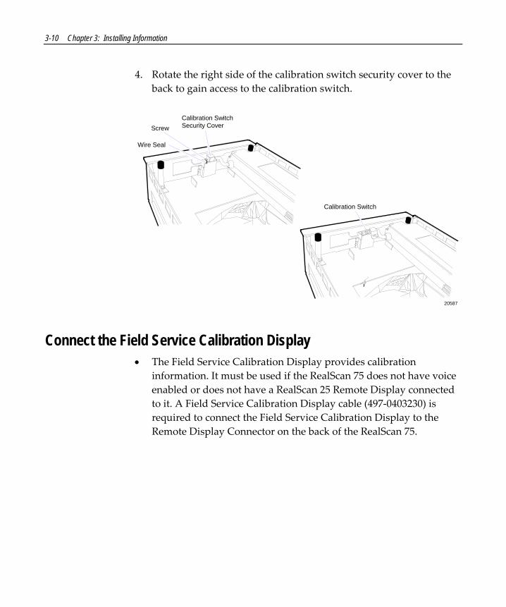
3-10 Chapter 3: Installing Information
4. Rotate the right side of the calibration switch security cover to the back to gain access to the calibration switch.
Screw
Wire Seal
Calibration SwitchSecurity Cover
20587
Calibration Switch
Connect the Field Service Calibration Display • The Field Service Calibration Display provides calibration
information. It must be used if the RealScan 75 does not have voice enabled or does not have a RealScan 25 Remote Display connected to it. A Field Service Calibration Display cable (497‐0403230) is required to connect the Field Service Calibration Display to the Remote Display Connector on the back of the RealScan 75.

Chapter 3: Installing Information 3-11
Perform Calibration Procedure The scale firmware controls the calibration procedure. It waits for a response to each prompt before going to the next step. The firmware uses the voice feature and the display to identify how much weight to place on the top plate. After the required weight has been placed on the top plate and pressed the Scale Zero button, the firmware sounds a single tone and goes to the next prompt.
The calibration procedure can be ended before completion by turning the unit off. However, if this is done, the scale must still be calibrated before placing it into service.
Note: The pound and kilogram weights used for calibration are not equivalent values. They are the actual weights the firmware needs to perform the calibration.
1. Install the Produce Guard if one is included.
2. Install the Top Plate.
3. Apply power to the RealScan 75.
4. Press and hold the Scale Zero button on the Operator Display Panel. The unit displays the Cal and PAr values. Record these values.
5. Raise the front edge of the top plate just enough to access the Calibration Switch. Press the Calibration Switch; then lower the front of the top plate into position. If a display is connected it should show Ready C‐0.000 kg (0.00 lb).
6. Change the weight on the top plate in the sequence shown in the following chart when directed to do so by the scaleʹs display or voice messages.

3-12 Chapter 3: Installing Information
22829B
Display Add Weight Remove Weight
C‐2.5 kg (05 lb.) 2.50 kg (5.00 lb.)
C‐10 kg (15 lb.) 7.50 kg (10.00 lb.)
C‐12.5 kg (30 lb.) Up to 5.0 lb 2.50 kg (15.00 lb.)
C‐00 kg (00 lb.) 12.5 kg (30.00 lb.)
0.000 kg (0.00 lb.)
If the scale is equipped with a Produce Guard or Electronic Article Surveillance (EAS), check for proper fit and alignment.
Note: Turn off the EAS system during calibration.
Place weights in circles shown when calibrating to ensure even distribution of weight during calibration.
Start in the center and work outward horizontally with increasing weight.
Don’t scatter weights around Top Plate.
If Scan Doctor detects an error during the calibration procedure, one of the following error codes may be given.
Error Code
Problem Suspect Components
1 ‐‐‐‐ Calibration error A/D output below 000h at digital to analog converter
Digital Board Load Cell
2 ‐‐‐‐ Calibration error A/D output below 280h at digital to analog converter
Digital Board Load Cell
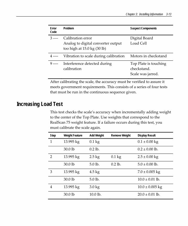
Chapter 3: Installing Information 3-13
Error Code
Problem Suspect Components
3 ‐‐‐‐ Calibration error Analog to digital converter output too high at 15.0 kg (30 lb)
Digital Board Load Cell
4 ‐‐‐‐ Vibration to scale during calibration Motors in checkstand
9 ‐‐‐‐ Interference detected during calibration
Top Plate is touching checkstand. Scale was jarred.
After calibrating the scale, the accuracy must be verified to assure it meets government requirements. This consists of a series of four tests that must be run in the continuous sequence given.
Increasing Load Test This test checks the scale’s accuracy when incrementally adding weight to the center of the Top Plate. Use weights that correspond to the RealScan 75 weight feature. If a failure occurs during this test, you must calibrate the scale again.
Step Weight Feature Add Weight Remove Weight Display Result
1 13.995 kg 0.1 kg 0.1 ± 0.00 kg
30.0 lb 0.2 lb. 0.2 ± 0.00 lb.
2 13.995 kg 2.5 kg 0.1 kg 2.5 ± 0.00 kg
30.0 lb 5.0 lb. 0.2 lb. 5.0 ± 0.00 lb.
3 13.995 kg 4.5 kg 7.0 ± 0.005 kg
30.0 lb 5.0 lb. 10.0 ± 0.01 lb.
4 13.995 kg 3.0 kg 10.0 ± 0.005 kg
30.0 lb 10.0 lb. 20.0 ± 0.01 lb.

3-14 Chapter 3: Installing Information
Step Weight Feature Add Weight Remove Weight Display Result
5 13.995 kg 3.995 kg 13.995 ± 0.005 kg
30.0 lb 10.0 lb. 30.0 ± 0.01 lb.
Note: Do not remove any weight from the Top Plate.
Over-Capacity Test This test checks for the proper indication from the scale when too much weight is placed on the top plate.
Note: This test must immediately follow the Increasing Load Test; do not remove any of the weights prior to running this test.
Place additional weight on the center of the top plate as shown in the following chart. Use the weight that corresponds to the RealScan 75 weight feature. The display shows a series of dashes to indicate an over‐capacity condition.
Step Weight Feature Add Weight Remove Weight Display Result
1 13.995 kg 0.04 kg ‐‐.‐‐‐
30.0 lb 0.08 lb. ‐‐.‐‐‐
2 13.995 kg 0.04 kg 13.995 ± 0.005 kg
30.0 lb 0.08 lb. 30.0 ± 0.01 lb.
Note: Do NOT remove any weight from the Top Plate.
Decreasing Load Test This test checks the scaleʹs accuracy when incrementally removing weight from the top plate. Use weights that correspond to the RealScan 75 weight feature.
Note: This test must immediately follow the Over‐Capacity Test; do not remove any of the weights prior to running this test.

Chapter 3: Installing Information 3-15
Step Weight Feature Add Weight Remove Weight Display Result
1 13.995 kg 3.995 kg 10.0 ± 0.005 kg
30.0 lb 10.0 lb. 20.0 ± 0.01 lb.
2 13.995 kg 7.5 kg 2.5 ± 0.00 kg
30.0 lb 15.0 lb. 5.0 ± 0.00 lb.
3 13.995 kg 0.1 kg 2.5 kg 0.1 ± 0.00 kg
30.0 lb 0.2 lb 5.0 lb. 0.2 ± 0.00 lb.
4 13.995 kg 0.1 kg 0.0 ± 0.00 kg
30.0 lb 0.2 lb. 0.0 ± 0.00 lb.
Shift Test This test involves moving a weight off the center point of the top plate to check for continued accuracy.
22829
EU Test Pattern
22829a
US Test Pattern
1. Place 5.00 kg (15.00 lb) on each of the 4 circles individually. The display must show 5.00 ± 0.005 kg (15.00 ± 0.01 lb) with a max of 0.005 kg (0.01 lb) between any of the 4 readings.
2. Remove all weights. The display must read 0.000 ± 0.000 kg (0.00 ± 0.00 lb). Test max 30 lb in center only.

3-16 Chapter 3: Installing Information
3. Press and hold the Scale Zero Button. Record the Cal and PAr values shown on the display.
Note: Circles are half way from Top Plate center to corners for the EU Test Pattern and half way from Top Plate center to the edges for the US Test Pattern.
Secure the Calibration Switch When performing a scale calibration, someone must attach a seal to the scale calibration security cover. Depending on the local laws, Weights and Measures officials may be required to attach the seal.
Note: In the United States and Canada, the audit trail can serve as an acceptable security seal when the RealScan 25 Compact Display is present.
RealScan 75-2xxx 1. Remove the Top Plate.
2. Remove the Produce Guard if one is included.
3. Rotate the calibration switch security cover until the screw holes and the seal holes are aligned.
Screw
Seal
Calibration SwitchSecurity Cover
Calibration Switch
15070
4. Install the screw to secure the calibration switch security cover.

Chapter 3: Installing Information 3-17
5. Seal the calibration switch security cover with one of the following seals.
• Lead/Wire Seal (NCR Part Number: 603‐8001097) using a Lead/Wire Seal Press (NCR Part Number: 603‐9000157)
• Film/Paper Seal (Obtain locally—Must meet the requirements of your local government)
Note: When you perform a scale certification, someone must attach a seal to the scale calibration security cover. Depending on your local laws, Weights and Measures officials may be required to attach the seal.
6. Install the calibration switch cover by inserting the right side into the mounting hole and pressing the left side down until it latches into place.
Calibration Switch Cover
14962
7. If a Produce Guard is included, set it on the Top Plate Support Posts.
8. Set the Top Plate on the unit so that it sits properly on the Top Plate Support Posts. If the RealScan 75 does not have a Produce Guard, the Support Posts have a rubber bumper on top that locates the Top Plate.
9. Verify that the display indicates 0.000 kg (0.00 lb).
10. Press and hold the Scale Zero button on the operator display panel. Verify the Cal value has incremented by 1. Record the Cal and PAr values, shown on the display, on the Placed Into Service form if required by your local Weights and Measures regulations.

3-18 Chapter 3: Installing Information
RealScan 75-8xxx 1. Remove the Top Plate—do not remove the Produce Guard if one is
included.
2. Rotate the calibration switch security cover until the screw holes and the seal holes are aligned.
Screw
Wire Seal
Calibration SwitchSecurity Cover
20587
Calibration Switch
3. Install the screw to secure the calibration switch security cover.
4. Seal the calibration switch security cover with one of the following seals.
• Lead/Wire Seal (NCR Part Number: 603‐8001097) using a Lead/Wire Seal Press (NCR Part Number: 603‐9000157)
• Film/Paper Seal (Obtain locally—Must meet the requirements of your local government)
Note: When you perform a scale certification, someone must attach a seal to the scale calibration security cover. Depending on your local laws, Weights and Measures officials may be required to attach the seal.

Chapter 3: Installing Information 3-19
5. Set the Top Plate on the unit so that it sits properly on the Top Plate Support Posts.
6. Verify that the display indicates 0.000 kg (0.00 lb).
7. Press and hold the Scale Zero button on the operator display panel. Verify the Cal value has incremented by 1. Record the Cal and PAr values, shown on the display, on the Placed Into Service form if required by your local Weights and Measures regulations.
Note: A short version of the above instruction is included in Appendix D for personnel who are fully familiar with the calibration process. The short form (497‐0439973) is also included in the box with each scanner/scale model.
3-20 Chapter 3: Installing Information
Step 4–Determine If Unit Is Operational When power is applied to the RealScan 75, it automatically performs Level 0 Diagnostics to check various components.
NCR RealScan 75-1xxx/3xxx/4xxx/7xxx Scanner After passing Level 0 diagnostics the Status indicator flashes green, a tone sounds, then the Status indicator turns red. The RealScan 75 is now operational.
NCR RealScan 75-2xxx/8xxx Scanner/Scale After passing Level 0 diagnostics the RealScan 75 runs scale diagnostics. During this time, all segments on the integrated or remote display are turned ON so the operator can verify the display works correctly. Then the display reads Ready 0.000 kg (Ready 0.00 lb). The Status Indicator flashes red for five seconds, then the Status indicator flashes green momentarily, a tone sounds, and the Status indictor turns red. The RealScan 75‐2xxx/8xxx is now operational.
If the RealScan 75 Does Not Pass Level O Diagnostics If an error occurs during Level 0 diagnostics, the integrated or remote display (if the unit has one) displays an error code, and if enabled, the RealScan 75 emits an audible description of the error and what action to take. There may be some simple steps you can take to correct the problem. See Troubleshooting. If you cannot correct the problem, contact NCR for warranty information.

Chapter 3: Installing Information 3-21
Checkout Reading Operation To check the tag reading operation of the RealScan 75, attempt to read a good tag on an item. The Status indicator turns red when the RealScan 75 is ready to scan a label. A good read is indicated when the Status indicator turns green and a tone sounds (if enabled).
Check Sensormatic® Deactivation System If you installed a RealScan 75‐7xxx/8xxx with the Sensormatic® Deactivation System, check out the deactivation function. Obtain a security tag. Scan a bar code and within two seconds pass the security tag through the deactivation zone. The Deactivated Tone should sound if it is enabled. Refer to Operating the Sensormatic® Deactivation System for detailed operating instructions.
Programming Your RealScan 75 comes from the factory with the programming parameters set to default values. The Communications Protocol is set to the specifications on your order. However, you may want to make some parameter changes for your particular installation.
Determine Communication Protocol Use the following procedure to determine the communications protocol programmed in your RealScan 75.
1. Apply power to the RealScan 75.

3-22 Chapter 3: Installing Information
2. Scan the Diagnostic Mode tag; must be first tag scanned after applying power. Scan the Hex 3 tag. The good read tone for this tag sounds (three beeps). If the RealScan 75 has the Voice feature enabled, the communications protocol is given audibly. If the Voice feature is not enabled, the Status indicator flashes green and the tone beeps, identifying the communication protocol. Following are the number of beeps that sound for each communication protocol.
3 Beeps IBM 468x Port 4A (Slot Scanner)
4 Beeps IBM 468x Port 4B (HHBCR)
6 Beeps RS‐232
11 Beeps Casio 4‐Bit Parallel Dual Cable
12 Beeps IBM 1520 (BCR)
13 Beeps TEC 4‐Bit Parallel Dual Cable
3. Remove power from the RealScan 75.

Chapter 3: Installing Information 3-23
Special Installations The RealScan 75 can be configured for a variety of installations. Some of these installations require specific cables, specific programming, or special installation procedures.
Convenience Stores Convenience stores require scanner performance similar to a supermarket. The RealScan 75 scanner comes already programmed for use with four different non‐NCR terminals. When ordering one of these features, you also need to order the interface cable. The following table identifies the four terminals, the interface cable, and the port for connecting the cable. Also included are the program parameters set at the factory. These parameter values are different from the standard default values.

3-24 Chapter 3: Installing Information
16385
Host Terminal Interface Cable
Gilbarco 1416-C237-0040Port Programming Parameters
Wayne 1416-C236-0040
Verifone 1416-C254-0040 Verifone
COM 6 orTerminal
Siemens Nixdorg 1416-C263-0040
Communications Protocol- RS-232TCR-15 System
GilbarcoconsoleJ207 WandReader
RS-232 Parameters 1- 2400 Baud- Even Parity- RTS Low/CTS Ignored
- 0D ASCII CodeRS-232 Terminator Byte
Plus 3 SystemWayneterminalScannerPort
Communications Protocol- RS-232
Bar Codes 1- Enable Extend UPC-E to UPC-A
Ruby System
COM 1
Communications Protocol- RS-232
Bar Codes 1- Enable Extend UPC-E to UPC-A
RS-232 Parameters 1- 1200 Baud- No Parity- 1 Stop Bit, 8-Bit Character- RTS Low, Wait for CTS
- 0A ASCII CodeRS-232 Terminator Byte
(Beetle Terminal)COM 2 Communications Protocol
- RS-232RS-232 Parameters 1
- 1 Stop Bit, 8-Bit Character
RealScan 2170 Host Terminal
Programming the RealScan 75-1xxx/3xxx/7xxx When connecting the RealScan 75‐1xxx/3xxx/7xxx to an NCR 2170 Terminal, you must set the scanner to the following RS‐232 parameters.
• 9600 baud • 1 Stop Bit • 7‐Bit character • Odd parity
Chapter 3: Installing Information 3-25
• RTS High, Wait for CTS • BCC disabled Set these parameters according to the following procedure:
1. Apply power to the RealScan 75.
2. Scan the Default tag to set all parameters to default values.
3. Scan the Programming Mode to put the RealScan 75 in the Base Programming state.
4. Scan the Hex 1 followed by Hex 0 to select the Communications Protocol programming mode.
5. Scan the Hex 5 to select RS‐232 communications.
6. Scan the Hex 2 followed by Hex 1 to select RS‐232 Parameters 2 Programming Mode.
7. Scan the Hex A to select the BCC Options parameter.
8. Scan the Hex 0 to disable BCC on bar code data.
9. Scan the Save and Reset to save the program changes.
Setting up the NCR 2170 Terminal Set up the NCR 2170 according to the following procedure.
1. Connect the RealScan 75 scanner cable to the NCR 2170 RS‐232 port with an ID = 04.
2. Set the NCR 2170 to default RS‐232 options.
3. Perform a Master Reset on the NCR 2170 by turning the key to P2 until the menu is displayed.

3-26 Chapter 3: Installing Information
Scale Address for IBM Communications Most IBM systems have software called Integrated Scanner/Scale that permits a single‐cable installation. You can check the terminal configuration at the controller to be sure this IBM option is activated. Once chosen, the scale address is 6E (default setting), and no other action is required other than plugging the RealScan 75 interface cable into port 17 (468x). This is the preferred and most common configuration. For the 4682/469x series IBM terminals, the RealScan 75 interface cable plugs into port 9B. This series has no port 17.
Some older 468x systems require a dual‐cable system, where one cable connects to the scanner and the other connects to the scale. The scale cable usually plugs into port 21 of a ʺBʺ or ʺCʺ feature card. It is possible to preserve the existing terminal configuration and still use the single‐cable feature of the REALSCAN 75. If there are no other ports used on the ʺBʺ or ʺCʺ feature card, you can remove the feature card from the terminal even though it is configured to be installed.
• If the card was in slot 2A, program the RealScan 75 scale address to 6A and plug the RealScan 75 Interface Cable into port 17.
• If the card was in slot 2B, program the RealScan 75 scale address to 6B and plug the RealScan 75 Interface Cable into port 17.
• If other ports beside port 21 are used on the ʺBʺ or ʺCʺ card and the other card slot is empty (2A or 2B), you can still use this procedure, but you must change the terminal configuration to define that there is a card in the empty slot and that its port 21 is connected to a scale. Program the scale to the empty slot address (2A = 6A, 2B = 6B). The existing card port 21 must be configured as not used and must not be removed from the terminal.
• If both card slots are used on the terminal, the terminal software must be a version that can be configured to support an integrated scanner/scale. This may require upgrading the software.

Chapter 3: Installing Information 3-27
SNI Beetle Terminal For the RealScan 75 to communicate with an SNI Beetle terminal, the communication parameters must be properly set. Scanning the following sequence of programming tags enables a typical installation; however, some variations may be necessary for any specific installation. The following programming tags must be the first ones scanned after applying power to the RealScan 75.
1. Default – sets parameters to previously defined default values.
2. Programming Mode – enables programming.
3. Hex 1, Hex 0, Hex 5 – RS‐232 communications.
4. Hex 2, Hex 0, Hex 5, Hex 1, Hex 0, Hex 5 – RS‐232 parameters.
• 9600 baud • Even parity • 1 Stop bit, 7‐bit character • RTS high, wait for CTS
5. Hex 2, Hex 2, Hex A, Hex 1 – enable prefix byte 02
6. Save and Reset – saves the program and resets the unit.
If the RealScan 75 contains a scale, the unit must be programmed to be identified as a scanner only. This is done by scanning the following sequence of programming tags.
1. Programming Mode – enables programming.
2. Hex 2, Hex 4, Hex 4 – identifies unit as scanner only.
3. Save and Reset – saves the program and resets the unit.
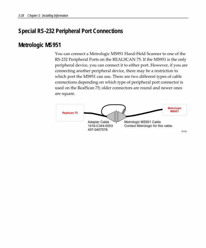
3-28 Chapter 3: Installing Information
Special RS-232 Peripheral Port Connections
Metrologic MS951 You can connect a Metrologic MS951 Hand‐Held Scanner to one of the RS‐232 Peripheral Ports on the REALSCAN 75. If the MS951 is the only peripheral device, you can connect it to either port. However, if you are connecting another peripheral device, there may be a restriction to which port the MS951 can use. There are two different types of cable connections depending on which type of peripheral port connector is used on the RealScan 75; older connectors are round and newer ones are square.
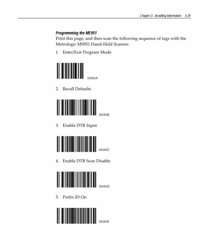
Chapter 3: Installing Information 3-29
Programming the MS951 Print this page, and then scan the following sequence of tags with the Metrologic MS951 Hand‐Held Scanner.
1. Enter/Exit Program Mode
16161A
2. Recall Defaults
16161B
3. Enable DTR Input
16161C
4. Enable DTR Scan Disable
16161D
5. Prefix ID On
16161E

3-30 Chapter 3: Installing Information
6. Disable Code 39
16161F
7. Disable Code 128
16161G
8. Disable Interleaved 2 of 5
16161H
9. No Tone
16161I
10. Enter/Exit Program Mode
16161A
Verify Installation 1. Apply power to the RealScan 75 by turning on the circuit breaker.
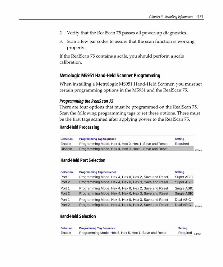
Chapter 3: Installing Information 3-31
2. Verify that the RealScan 75 passes all power‐up diagnostics.
3. Scan a few bar codes to assure that the scan function is working properly.
If the RealScan 75 contains a scale, you should perform a scale calibration.
Metrologic MS951 Hand-Held Scanner Programming When installing a Metrologic MS951 Hand‐Held Scanner, you must set certain programming options in the MS951 and the RealScan 75.
Programming the RealScan 75 There are four options that must be programmed on the RealScan 75. Scan the following programming tags to set these options. These must be the first tags scanned after applying power to the RealScan 75.
Hand-Held Processing
Selection Programming Tag Sequence
Enable Programming Mode, Hex 4, Hex 0, Hex 1, Save and ResetSetting
DisableRequired
Programming Mode, Hex 4, Hex 0, Hex 0, Save and Reset 16386A
Hand-Held Port Selection
Selection Programming Tag Sequence
Port 1 Programming Mode, Hex 4, Hex 0, Hex 2, Save and Reset
Setting
Port 2Single ASIC
Programming Mode, Hex 4, Hex 0, Hex 3, Save and Reset
16386B
Single ASIC
Port 1 Programming Mode, Hex 4, Hex 0, Hex 3, Save and ResetPort 2
Dual ASICProgramming Mode, Hex 4, Hex 0, Hex 2, Save and Reset Dual ASIC
Port 1 Programming Mode, Hex 4, Hex 0, Hex 2, Save and ResetPort 2
Super ASICProgramming Mode, Hex 4, Hex 0, Hex 3, Save and Reset Super ASIC
Hand-Held Selection
24855
Selection Programming Tag Sequence
Enable Programming Mode, Hex 5, Hex 5, Hex 1, Save and Reset RequiredSetting

3-32 Chapter 3: Installing Information
Hand-Held Beep on the RealScan 75
Selection Programming Tag Sequence
Enable Programming Mode, Hex 4, Hex 0, Hex 5, Save and ResetSetting
DisableRequired
Programming Mode, Hex 4, Hex 0, Hex 4, Save and Reset 16386D
RealScan 32 Hand-Held Scanner The RealScan 32 Hand‐Held Scanner can be connected to one of the RS‐232 Peripheral Ports on the RealScan 75. If the RealScan 32 is the only peripheral device, you can connect it to either port. However, if you are connecting another peripheral device, there may be a restriction to which port the RealScan 32 can use.
RealScan 32
RealScan 32 Serial Cable DB91416-C864-0020497-0429607
RealScan 75
20964
Programming the RealScan 32 Scan the following sequence of programming tags found in the NCR RealScan 32 Operatorʹs Guide.
1. Scan the NCR Factory Defaults tag.
2. Scan the Disable STX tag.
3. Scan the Disable LF tag.
4. Scan the Disable ACK tag.
5. Scan the Disable Beep tag.
When installing an NCR RealScan 32 Hand‐Held Scanner, you must set certain programming options in both the RealScan 75 and the RealScan 32. These options are given as follows.

Chapter 3: Installing Information 3-33
Programming the RealScan 75 There are four options that must be programmed on the RealScan 75. Scan the following programming tags to set these options. These must be the first tags scanned after applying power to the RealScan 75.
Hand-Held Processing
Selection Programming Tag Sequence
Enable Programming Mode, Hex 4, Hex 0, Hex 1, Save and ResetSetting
DisableRequired
Programming Mode, Hex 4, Hex 0, Hex 0, Save and Reset 16386A
Hand-Held Port Selection
Selection Programming Tag Sequence
Port 1 Programming Mode, Hex 4, Hex 0, Hex 2, Save and Reset
Setting
Port 2Single ASIC
Programming Mode, Hex 4, Hex 0, Hex 3, Save and Reset
16386B
Single ASIC
Port 1 Programming Mode, Hex 4, Hex 0, Hex 3, Save and ResetPort 2
Dual ASICProgramming Mode, Hex 4, Hex 0, Hex 2, Save and Reset Dual ASIC
Port 1 Programming Mode, Hex 4, Hex 0, Hex 2, Save and ResetPort 2
Super ASICProgramming Mode, Hex 4, Hex 0, Hex 3, Save and Reset Super ASIC
Hand-Held Selection
24855
Selection Programming Tag Sequence
Enable Programming Mode, Hex 5, Hex 5, Hex 1, Save and Reset RequiredSetting
Hand-Held Beep on the RealScan 75
Selection Programming Tag Sequence
Enable Programming Mode, Hex 4, Hex 0, Hex 5, Save and ResetSetting
DisableRequired
Programming Mode, Hex 4, Hex 0, Hex 4, Save and Reset 16386D

3-34 Chapter 3: Installing Information
RealScan 35/36 Hand-Held Scanner connection The RealScan 35/36 Hand‐Held Scanner can be connected to one of the RS‐232 Peripheral Ports on the RealScan 75. If the RealScan 35/36 is the only peripheral device, you can connect it to either port. However, if you are connecting another peripheral device, there may be a restriction to which port the RealScan 35/36 can use. There are two different types of cable connections depending on which type of peripheral port connector is used on the RealScan 75; older connectors are round and newer ones are square.
Serial Number Above 32660591
RealScan 35/36
Extension Cable1416-C397-0010497-0410118
RealScan 35/36 Cable1416-C313-0040497-0406911
RealScan 75
16145
Note: The Extension Cable is not required, but is recommended due to the length of the RealScan 35/36 Cable.
Serial Number Below 32660592
RealScan 35/36
Adapter Cable1416-C344-0003497-0407578
RealScan 35/36 Cable1416-C088-0040497-0301513
RealScan 75
16142
Programming the RealScan 35/36 Set the RealScan 35/36 programming by scanning the appropriate programming tags in the NCR RealScan 35/36 Userʹs Guide.
1. Scan the Select Serial tag (tag CO).
2. Scan the Reset To Serial Default tag (tag ZA).

Chapter 3: Installing Information 3-35
3. Scan the Protocol = CTS(+) tag (tag HC).
4. Scan the No Buffering tag (tag NF).
5. Scan the Enable UPC & E With Supplement Disabled tag (tag QC).
6. Scan the Enable EAN With Supplement Disabled tag (tag RC).
7. Scan the Enable Number System Digit tag (tag RE).
8. Scan the Enable Check Digit tag (tag RG).
9. Scan the Disable Code 39 tag (tag OA).
10. Scan the Disable Code 128 tag (tag TA).
11. Scan the Enable Symbology ID tag (tag FB).
12. Scan the Set ICL Symbology Table tag (tag FC).
You can program the RealScan 35/36 to beep when it successfully reads a bar code. Do this by scanning the appropriate tag.
• Enable ‐ Scan the Beeper On tag (tag AD). • Disable ‐ Scan the Beeper Off tag (tag AA). Refer to the RealScan 35/36 Userʹs Guide for additional programming information.
Programming the RealScan 75 When installing an NCR RealScan 35/36 Hand‐Held Scanner, you must set certain programming options in both the RealScan 75 and the RealScan 35/36.
There are four options that must be programmed on the RealScan 75. Scan the following programming tags to set these options. These must be the first tags scanned after applying power to the RealScan 75.
Hand-Held Processing
Selection Programming Tag Sequence
Enable Programming Mode, Hex 4, Hex 0, Hex 1, Save and ResetSetting
DisableRequired
Programming Mode, Hex 4, Hex 0, Hex 0, Save and Reset 16386A
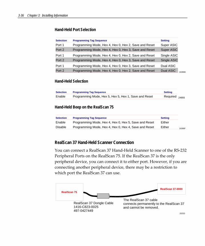
3-36 Chapter 3: Installing Information
Hand-Held Port Selection
Selection Programming Tag Sequence
Port 1 Programming Mode, Hex 4, Hex 0, Hex 2, Save and Reset
Setting
Port 2Single ASIC
Programming Mode, Hex 4, Hex 0, Hex 3, Save and Reset
16386B
Single ASIC
Port 1 Programming Mode, Hex 4, Hex 0, Hex 3, Save and ResetPort 2
Dual ASICProgramming Mode, Hex 4, Hex 0, Hex 2, Save and Reset Dual ASIC
Port 1 Programming Mode, Hex 4, Hex 0, Hex 2, Save and ResetPort 2
Super ASICProgramming Mode, Hex 4, Hex 0, Hex 3, Save and Reset Super ASIC
Hand-Held Selection
24855
Selection Programming Tag Sequence
Enable Programming Mode, Hex 5, Hex 5, Hex 1, Save and Reset RequiredSetting
Hand-Held Beep on the RealScan 75
Selection Programming Tag Sequence
Enable Programming Mode, Hex 4, Hex 0, Hex 5, Save and ResetSetting
DisableEither
Programming Mode, Hex 4, Hex 0, Hex 4, Save and Reset 16386FEither
RealScan 37 Hand-Held Scanner Connection You can connect a RealScan 37 Hand‐Held Scanner to one of the RS‐232 Peripheral Ports on the RealScan 75. If the RealScan 37 is the only peripheral device, you can connect it to either port. However, if you are connecting another peripheral device, there may be a restriction to which port the RealScan 37 can use.
The RealScan 37 cable connects permanently to the RealScan 37 and cannot be removed.
20253
RealScan 37-0000
RealScan 37 Dongle Cable1416-C823-0025497-0427449
RealScan 75

Chapter 3: Installing Information 3-37
Programming the RealScan 37 Program the NCR RealScan 37‐1xxx by scanning the following six bar codes. If the RealScan 37 gives a triple beep, start over with the first bar code. Refer to the NCR RealScan 37 Userʹs Guide for more specific information.
1. Factory Default
2. RS‐232, 7 Data, 1 Stop, Space Parity
3. Data Format Number 1
4. Data Format Number 2
5. Data Format Number 3
6. Data Format Number 4

3-38 Chapter 3: Installing Information
7. RTS/CTS
Programming the RealScan 75 When installing a RealScan 37 Scanner, you must set certain programming options in both the RealScan 75 and the RealScan 37. These options are given as follows.
There are four options that must be programmed on the RealScan 75. Scan the following programming tags to set these options. These must be the first tags scanned after applying power to the RealScan 75.
Hand-Held Processing
Selection Programming Tag Sequence
Enable Programming Mode, Hex 4, Hex 0, Hex 1, Save and ResetSetting
DisableRequired
Programming Mode, Hex 4, Hex 0, Hex 0, Save and Reset 16386A
Hand-Held Port Selection
Selection Programming Tag Sequence
Port 1 Programming Mode, Hex 4, Hex 0, Hex 2, Save and Reset
Setting
Port 2Single ASIC
Programming Mode, Hex 4, Hex 0, Hex 3, Save and Reset
16386B
Single ASIC
Port 1 Programming Mode, Hex 4, Hex 0, Hex 3, Save and ResetPort 2
Dual ASICProgramming Mode, Hex 4, Hex 0, Hex 2, Save and Reset Dual ASIC
Port 1 Programming Mode, Hex 4, Hex 0, Hex 2, Save and ResetPort 2
Super ASICProgramming Mode, Hex 4, Hex 0, Hex 3, Save and Reset Super ASIC

Chapter 3: Installing Information 3-39
Hand-Held Selection
24855
Selection Programming Tag Sequence
Enable Programming Mode, Hex 5, Hex 5, Hex 1, Save and Reset RequiredSetting
Hand-Held Beep on RealScan 75
Selection Programming Tag Sequence
Enable Programming Mode, Hex 4, Hex 0, Hex 5, Save and ResetSetting
DisableRequired
Programming Mode, Hex 4, Hex 0, Hex 4, Save and Reset 16386D
External Sensormatic® Tag Deactivation System Note: This does not apply to the RealScan 75‐7xxx/8xxx. These units have a Sensormatic® deactivation device installed below the Top Plate that connects directly to a Sensormatic® controller.
The external Sensormatic® tag deactivation system must be connected to the RS‐232 Peripheral Ports, Port 2. If you also have a hand‐held scanner, it must be connected to Port 1. When the RealScan 75 Scanner reads a tag, the Sensormatic® hardware needs to receive an interlock signal for it to function. When the system is installed, you must enable the Sensormatic® Interlock Signal.
Enable Sensormatic® Interlock Signal Scan the following sequence of programming tags to enable the Sensormatic® Interlock signal. These must be the first tags scanned after applying power to the RealScan 75.
1. Programming Mode – Puts scanner in the programming mode.
2. Hex 4, Hex 2, and Hex B – Enables Sensormatic® Interlock Signal.
3. Save and Reset – Saves the enabled setting, then resets the RealScan 75

3-40 Chapter 3: Installing Information
Disable Sensormatic® Interlock Signal Scan the following sequence of programming tags to disable the Sensormatic® Interlock signal. These must be the first tags scanned after applying power to the RealScan 75.
1. Programming Mode – Puts scanner in the programming mode.
2. Hex 4, Hex 2, and Hex A – Disables Sensormatic® Interlock Signal.
3. Save and Reset – Stores the disabled setting, then resets the RealScan 75
Symbol Technologies LS4000 The Symbol Technologies LS4000 Hand‐Held Scanner can be connected to one of the RS‐232 Peripheral Ports on the RealScan 75. If the LS4000 is the only peripheral device, you can connect it to either port. However, if you are connecting another peripheral device, there may be a restriction to which port the LS4000 can use. There are two different types of cable connections depending on which type of peripheral port connector is used on the RealScan 75; older connectors are round and newer ones are square.
Serial Number Above 32660591

Chapter 3: Installing Information 3-41
Serial Number Below 32660592
Programming the LS4000 Print this page, then scan the following sequence of tags with the Symbol Technologies LS4000 Hand‐Held Scanner.
1. Set All Defaults
16161A 2. ICL RS‐232
16161B 3. Do Not Beep After Good Decode
16161C 4. Disable UCC/EAN‐128
16161D

3-42 Chapter 3: Installing Information
5. Disable Code 128
16161E 6. Disable Code 39
16161F 7. Disable Interleaved 2 of 5
16161G 8. RTS/CTS Option 2
16161H 9. Host: Low RTS
16161I 10. Host Serial Response Time‐Out
16161J 11. 0
16161K 12. 5
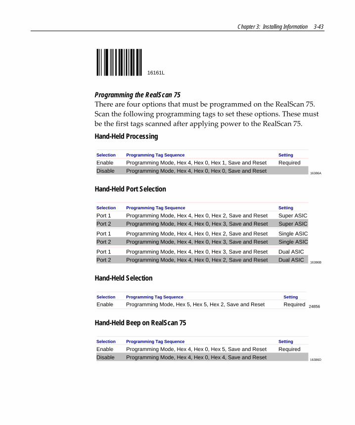
Chapter 3: Installing Information 3-43
16161L
Programming the RealScan 75 There are four options that must be programmed on the RealScan 75. Scan the following programming tags to set these options. These must be the first tags scanned after applying power to the RealScan 75.
Hand-Held Processing
Selection Programming Tag Sequence
Enable Programming Mode, Hex 4, Hex 0, Hex 1, Save and ResetSetting
DisableRequired
Programming Mode, Hex 4, Hex 0, Hex 0, Save and Reset 16386A
Hand-Held Port Selection
Selection Programming Tag Sequence
Port 1 Programming Mode, Hex 4, Hex 0, Hex 2, Save and Reset
Setting
Port 2Single ASIC
Programming Mode, Hex 4, Hex 0, Hex 3, Save and Reset
16386B
Single ASIC
Port 1 Programming Mode, Hex 4, Hex 0, Hex 3, Save and ResetPort 2
Dual ASICProgramming Mode, Hex 4, Hex 0, Hex 2, Save and Reset Dual ASIC
Port 1 Programming Mode, Hex 4, Hex 0, Hex 2, Save and ResetPort 2
Super ASICProgramming Mode, Hex 4, Hex 0, Hex 3, Save and Reset Super ASIC
Hand-Held Selection
24856
Selection Programming Tag Sequence
Enable Programming Mode, Hex 5, Hex 5, Hex 2, Save and Reset RequiredSetting
Hand-Held Beep on RealScan 75
Selection Programming Tag Sequence
Enable Programming Mode, Hex 4, Hex 0, Hex 5, Save and ResetSetting
DisableRequired
Programming Mode, Hex 4, Hex 0, Hex 4, Save and Reset 16386D


Chapter 4: Operating Information
The NCR RealScan 75 requires very little attention during operation. It is designed to reduce the amount of bar code orientation prior to scanning an item. Because of the bi‐optic design and the PACESETTER functionality, most people become proficient in a very short time.
4

4-2 Chapter 4: Operating Information
Scanner/Scale Components
22594
A
F
E
D
C
B
IHG
K
J
L
A – Motion Detector
B – Volume Adjust Button
C – Window Maintenance Indicator
D – Scale Zero Button
E – Status Indicator
F – Speaker
G – Operator Display Panel
H – Integrated Display
I – Remote Compact Display (Optional)
J – Vertical Scan Window
K – Top Plate
L – Horizontal Scan Window

Chapter 4: Operating Information 4-3
Motion Detector The Motion Detector is located in the lower portion of the Operator Display Panel. To prolong the life of the RealScan 75, when there is no operator activity for an extended time (the default period is 15 minutes), the laser diode and motor are turned off. To turn on the RealScan 75, you must activate the unit by passing an item in front of the motion detector. This movement is the normal item scanning movement.
Volume Adjust Button The RealScan 75 has a Volume Adjust button located on the Operator Display Panel. A picture of a speaker emitting sound waves identifies the Volume Adjust button. The purpose of the Volume Adjust button is to permit the operator to change the scannerʹs Good Read tone volume to a comfortable level depending on the ambient noise level at the time. If enabled through programming, it also permits the operator to change the frequency (tone) of the Good Read tone.
Each time you momentarily press the button, the Good Read tone changes its volume and sounds a Good Read tone using the new setting. There are six or eleven different volume settings possible depending on how the Volume Adjust button is programmed. Repeatedly pressing the Volume Adjust button increases the volume to the maximum setting and then repeats the cycle from minimum back up to maximum. However, the scanner reverts to the programmed volume setting at each power‐up.
If the Volume Adjust button is programmed to change the tone, holding the button pressed for more than one second changes the Good Read tone to the next tone. Repeatedly doing this causes the tone to increase to the maximum and then start over with the lowest.
Note: Permanent changes to tone volume and tone frequency requires changing the program. Refer to Chapter 6: Programming Information.

4-4 Chapter 4: Operating Information
Window Maintenance Indicator The RealScan 75 has a Window Maintenance indicator light located on the Operator Display Panel. A picture of a hand moving a towel in a wiping motion identifies the Window Maintenance light. When the dirty window indicator is (yellow light) ON and flashing, it indicates that the scanner Top Plate window has become dirty and needs to be cleaned for optimum scanner performance. It is also occasionally necessary to clean the window located under the Top Plate to remove loose debris or dust. This indicator light may also come on if the glass has excessive scratches.
Scale Zero Button The Scale Zero button is located on the Operator Display Panel of the RealScan 75‐2xxx.
Note: The RealScan 75‐1xxx/3xxx/4xxx/7xxx Scanners have a blank plate where the Scale Zero button would be if the scale was installed.
Normally, the scale automatically re‐zeros itself when there is no weight on the Top Plate. If the Integrated Display or the RealScan 25 Remote Display is blank or indicates a weight other than zero, yet no weight is currently on the scale, pressing the Scale Zero button re‐zeros the scale. If the error code 5 ‐‐‐‐ displays on the Integrated Display or on the RealScan 25 Remote Display, remove any weight from the scale and press the Scale Zero button. If the error code persists, calibrate the scale before proceeding.
Chapter 4: Operating Information 4-5
Status Indicator A Red/Green Status indicator is located on the Operator Display Panel. When the Status indicator is red, the unit is in Standby mode waiting to read the next bar code label. When the RealScan 75 accurately reads a bar code, the Status indicator flashes green momentarily. The Status indicator then turns red and the RealScan 75 is ready to read the next bar code. If the scanner does not detect another bar code, the Status indicator remains red.
During power‐up, if the unit goes into the Failure mode, the Status indicator flashes red and green in a repeated pattern, with a gap of three seconds between each set of flashes. The number of flashes represents a particular scanner error code that is used by the Field Engineer to repair the unit. The Status indicator alternately toggles red and green when the RealScan 75 shuts down due to operator inactivity. In addition, voice messages are used to indicate errors.
When using IBM 468x communications, the Status indicator slowly flashes red when the RealScan 75 is off‐line. This can happen if the host terminal is not turned on, or the interface cable is not connected.
Speaker (Audible Tone/Voice Messages) A tone can be programmed to sound when the RealScan 75 accurately reads a bar code. The tone provides a means of determining a good read without having to observe the Status Indicator.
The Good Read tone can be enabled or disabled through programming. If the tone is enabled, you can also specify its frequency, volume, and duration. The details for programming the tone are described in Chapter 6: Programming Information. The RealScan 75 comes from the factory with the tone enabled. To adjust the Good Read tone temporarily, use the Volume Adjust button.
If voice is enabled, audible voice messages are heard during the following events.

4-6 Chapter 4: Operating Information
• When the scanner scale goes online or offline • When you check the communications protocol • When you test item tags using PACESETTER • When certain error conditions occur • When there is interference with the scale • When the scanner windows become dirty
Operator Display Panel The Operator Display Panel provides the interface to the operator. It contains the Status indicator, Reset button, Motion detector, Maintenance Window Indicator, Scale Zero Button, and Volume Adjust Button.
Integrated Display The Integrated Display is used to display weight and price information. The display is inset into the tower section of the RealScan 75. The information that is displayed depends on the capabilities of the host terminal.
The Integrated Display is also used to display error codes to indicate specific scale failures. When an error code is displayed, the scale does not operate until the error is corrected.
During scale calibration, certain messages are displayed on the integrated display that guide through the calibration procedure. Inspection audit trail information relating to calibration changes are also displayed when the Scale Zero button is pressed and held.

Chapter 4: Operating Information 4-7
Remote Display Using the RealScan 25 Remote Display is an option to display weight and price information in locations where the customer might not see the Integrated Display that is inset in the tower of the RealScan 75. The remote display connects to the back of the RealScan 75 with a cable.
The display is also used to display error codes to indicate specific scale failures. When an error code is displayed, the scale does not operate until the error is corrected.
During scale calibration, certain messages are displayed on the remote display that guides you through the calibration procedure. Inspection audit trail information relating to calibration changes are also displayed when the Scale Zero button is pressed and held.
Vertical Scan Window The RealScan 75 Vertical Scan Window is mounted in the tower cabinet that rises above the checkstand surface. This scan window provides a vertical scan pattern. The tower is designed to withstand occasional impact from elbows and purses.
Top Plate The stainless steel Top Plate contains the Horizontal Scan Window. Items being scanned are slid from the checkstand, across the Top Plate, and back onto the checkstand. The Top Plate also provides a surface for placing items when weighing them.
Occasionally dirt and debris can collect under the Top Plate, causing weighing problems. The Top Plate can be easily removed to clean these obstructions.

4-8 Chapter 4: Operating Information
Horizontal Scan Window The RealScan 75 Horizontal Scan Window is flush‐mounted in the stainless steel Top Plate. A scratch‐resistant glass window is standard. Optionally, a scratchproof window is available. This window provides a horizontal scan pattern.
The flush‐mounted horizontal window permits users to slide a product across the Top Plate without lifting the product. Furthermore, loosely wrapped products cannot snag on the Top Plate.

Chapter 4: Operating Information 4-9
Barcode Label Orientation Because the RealScan 75 produces an omni‐directional scan pattern, bar code labels can be read from many different angles. The RealScan 75 reads the labels on the leading side of a package, the trailing side, the bottom side, the top side, and the side opposite the operator. Products can be read from right to left or from left to right. A good rule of thumb is if you cannot see the bar code label, the RealScan 75 can.
Active Scan Zone
The active scan zone is the area where the unit can read a bar code label. Dashed lines in the illustrations indicate this area. The first illustration shows the scan zone for the leading, trailing, bottom, and the back (opposite the operator) sides. The second illustration shows the top‐down zone, where the unit can read the top of an item.

4-10 Chapter 4: Operating Information
Bar Code Quality Many labels in a typical retail environment are unreadable. The illustration shows some of the common problems. Vendors and printers regularly supply products to the market with bar codes that are overprinted, underprinted, or truncated. Some labels have missing margins. Others may be printed around the corners of packages, or on media not likely to remain flat when picked up.
0 1 2 3 4 6 7 85 90 6
01 2 3 4 6 7 85 90 6
01 2 3 4 6 7 85 90 6
R0026
0 1 2 3 4 6 7 85 90 6
0 1 2 3 4 6 7 85 90 601 2 3 4 6 7 85 90 6
Bar Code Scratched Bar Code Folded Bar Code Truncated
Bar Code Torn Poor Color Contrast Red Bar Code OnRed Background
The readability of a label depends on variables such as size, placement, color, paper type, ink viscosity, and package coatings. The middle of a printing run can yield erroneous labels due to the many variants involved. In particular, poor color contrast and marginal print quality can make a label hard to read.
A label should be considered readable if it meets or exceeds the requirements set forth in the UPC Symbol Specification published by the UPC Council, Inc. (March 1982), and the General Specification for Article Symbol Marking, Copyright EAN‐1977.

Chapter 4: Operating Information 4-11
Multiple Reads Only one good read is reported if a bar code label is placed on the scanner window and left there. The scanner firmware inhibits a second read of the same label if it occurs within a preset time of a good read. The preset time is programmable from 450ms to 1500ms, in increments of 150ms. The unit is set at 900ms when shipped from the factory. To read the label a second time, remove the label from the scan window and scan the label again after the time‐out period has elapsed.

4-12 Chapter 4: Operating Information
Operating Instructions There are certain functions and procedures that the operator needs to understand in order to be proficient at operating the RealScan 75.
Adjusting the Good Read Tone The RealScan 75 has a Volume Adjust button located on the Operator Display Panel. A picture of a speaker emitting sound waves identifies the Volume Adjust button. The purpose of the Volume Adjust button is to permit the operator to change the scannerʹs Good Read tone volume to a comfortable level depending on the ambient noise level at the time. If enabled through programming, it also permits the operator to change the frequency (tone) of the Good Read tone.
Each time you momentarily press the button, the Good Read tone changes its volume and sounds a Good Read tone using the new setting. There are six or eleven different volume settings possible depending on how the Volume Adjust button is programmed. Repeatedly pressing the Volume Adjust button increases the volume to the maximum setting and then repeats the cycle from minimum back up to maximum. However, the scanner reverts to the programmed volume setting at each power‐up.
If the Volume Adjust button is programmed to change the tone, holding the button pressed for more than one second changes the Good Read tone to the next tone. Repeatedly doing this causes the tone to increase to the maximum and then start over with the lowest.
Note: Permanent changes to tone volume and tone frequency require changing the program. See Chapter 6: Programming Information.

Chapter 4: Operating Information 4-13
Not-On-File Error The Not on File feature is available on the RealScan 75 only if your terminal has this capability. If a bar code label is not in the price lookup file, a special tone sounds three times a second and the Status indicator flashes red. The volume of the Not on File tone is programmable.
The RealScan 75 is disabled from reading additional tags until the error is cleared. To clear, press the terminal CLEAR key and manually enter the item and price.
Scanning Procedure

4-14 Chapter 4: Operating Information
Item orientation, motion, and sequential handling are required for proper scanner operation. To scan items with the RealScan 75 use the following procedure.
1. Verify the scanner is operable (Status indicator is red).
2. Pass the item across the RealScan 75 lower window.
3. If a good read occurs, the Status Indicator flashes green and a tone is emitted if programmed.
If the RealScan 75 is either a 7xxx or 8xxx model, the Sensormatic® Deactivation Device also deactivates the security tag if one is attached to the merchandise.
If the Status indicator remains red, the RealScan 75 did not read the bar code label. Try to orient the label so that it faces away from you and scan the item again. If this does not work, manually enter information for the item. Then continue to scan.
Turning the RealScan 75 On And Off The RealScan 75 has no ON/OFF switch. The checkout counter must have a circuit breaker switch that is accessible and located near the operator. Turn on the RealScan 75 by turning the circuit breaker switch ON. To turn off the RealScan 75, turn the circuit breaker switch to OFF.
When you supply power to the RealScan 75, it performs specific diagnostics that check various components. If a scale error occurs during these diagnostics, an error code is displayed on the Integrated Display or RealScan 25 Remote Display. If a scanner error occurs during these diagnostics, an error code tone sounds and the Status Indicator flashes to indicate the error. Call your supervisor, your Service Company, or NCR for assistance.
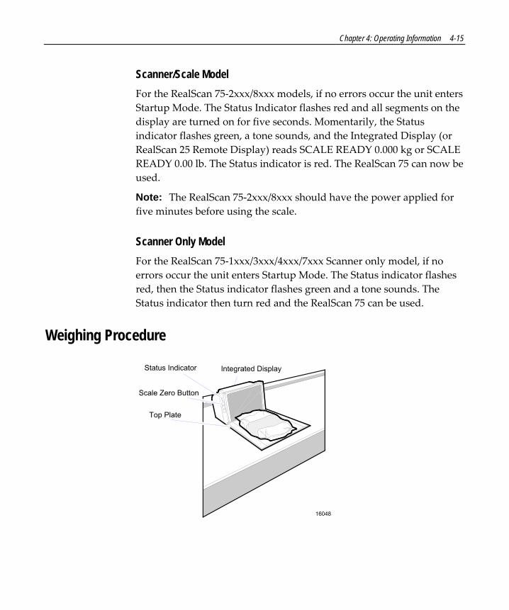
Chapter 4: Operating Information 4-15
Scanner/Scale Model For the RealScan 75‐2xxx/8xxx models, if no errors occur the unit enters Startup Mode. The Status Indicator flashes red and all segments on the display are turned on for five seconds. Momentarily, the Status indicator flashes green, a tone sounds, and the Integrated Display (or RealScan 25 Remote Display) reads SCALE READY 0.000 kg or SCALE READY 0.00 lb. The Status indicator is red. The RealScan 75 can now be used.
Note: The RealScan 75‐2xxx/8xxx should have the power applied for five minutes before using the scale.
Scanner Only Model For the RealScan 75‐1xxx/3xxx/4xxx/7xxx Scanner only model, if no errors occur the unit enters Startup Mode. The Status indicator flashes red, then the Status indicator flashes green and a tone sounds. The Status indicator then turn red and the RealScan 75 can be used.
Weighing Procedure

4-16 Chapter 4: Operating Information
The RealScan 75 has a maximum settling time of 0.90 seconds for items which weigh five pounds or less, and a maximum settling time of 2 seconds for items that weigh over five pounds. The scale does not function for items that weigh more than the maximum capacity of the scale – 9.995 kg, 13.995 kg, or 30.0 lb. (depending on the scale configuration).
The scale can be operated in Mode 1 or Mode 2, depending on your terminal and the type of RealScan 75 you have. In MODE 1, weight is displayed. In MODE 2, both weight and price are displayed.
Weigh items using the following procedure:
1. Verify the display reads SCALE READY 0.000 kg (0.00 lb).
2. If SCALE READY 0.000 kg (0.00 lb) is not displayed, reset the scale by pressing the Scale Zero button. If this does not work, turn the scanner circuit breaker OFF and then ON.
3. Pick up the item and place it in the center of the Top Plate. Make sure the item does not overhang, whatever is weighed must fit fully on the Top Plate. The item weight is displayed. Press the weight request key on the terminal. The weight is communicated to the terminal.
4. The Status indicator flashes green momentarily, a Good tone is emitted, and the Status indicator turns red to indicate a good weigh. No change indicates a bad weigh.
5. If a bad weigh occurs, weigh the package again. (Refer to Step 3.)
6. If the Status indicator is still red, remove the item from the Top Plate. Then remove the Top Plate and check for debris under it.
7. If there is debris, clean it.
8. Replace the Top Plate, then press the Scale Zero button to reset the scale.
9. Wait for the SCALE READY 0.000 kg (0.00 lb) message to be displayed. When it is displayed, weigh the item again.

Chapter 4: Operating Information 4-17
10. If the Status indicator is still red, contact your supervisor, your Service Company, or NCR Customer Services.
Note: If you have a RealScan 75‐4xxx with a Bizerba scale, refer to the Bizerba document that came with the scale for operating information.
Operating the Sensormatic® Deactivation System
Normal Operation The operating procedures can vary according to the parameter settings. The following procedure assumes the Sensormatic® parameters are set to the following values.
• Security tag deactivation function is enabled. • Security tag deactivated tone is enabled. • Security tag deactivated tone is set to a single long tone. • Security tag detected tone is enabled. Following procedure assumes the RealScan 75 and the Sensormatic® ScanMax™ Pro Controller are turned on and functioning properly.
1. Pass an item across the scanner.
2. As the bar code goes through the scan zone, the RealScan 75 reads it and sounds a Good Read tone.
3. As the security tag goes through the Sensormatic® deactivation zone, the Sensormatic® system deactivates the security tag and a Security Tag Deactivated tone sounds. This normally happens fast enough that the Security Tag Detected Tone does not sound.

4-18 Chapter 4: Operating Information
Note: The security tag must be detected by the Sensormatic® system with two seconds after the RealScan 75 reads the bar code. If more than two seconds elapse, the security tag is not deactivated even when it does come into the deactivation zone. In this case, the Security Tag Detected Tone sounds while the tag is in the deactivation zone. The sound is similar to a Geiger counter. When this condition occurs, the security tag must be deactivated manually.
Manual Deactivation If for some reason the security tag is not deactivated in the normal manner, it can be deactivated manually. This normally occurs when too much time elapses after the RealScan 75 reads the barcode. There are two ways to initiate a manual security tag deactivation.
1. Press the Volume button on the RealScan 75 or scan the Manual Deactivation tag. The RealScan 75 laser light and spinner motor turn off, disabling the scanner.
2. Pass the security tag into the deactivation zone. The Security Tag Detected Tone sounds (similar to a Geiger counter) and the tag is deactivated. The RealScan 75 laser light and spinner motor turn on, enabling the scanner.

Chapter 4: Operating Information 4-19
Cleaning Procedure The RealScan 75 should be kept in good operating condition by performing the following routine maintenance. Keeping the scan windows clean helps keep the read rate exceptionally high. During normal operation of the REALSCAN 75, the Horizontal Scan Window gets dirty. If you permit dirt to accumulate, performance degrades to the point where the scanner cannot read bar codes. The Horizontal Scan Window should be cleaned at least once a day:
Note: Before cleaning the RealScan 75, be sure to turn the circuit breaker switch off.
Note: When cleaning the RealScan 75, do not spray or pour the cleaning agent directly onto the RealScan 75. Moisten a soft cloth with the cleaning agent, then wipe the components you are cleaning.
Scanner Body 1. Clean the scanner body with a soft cloth dampened by lukewarm
water and a mild soap.
2. Wipe the surfaces dry with a soft, dry cloth.
Vertical Scan Window 1. Clean the Vertical Scan Window with a soft cloth damped with a
common, non‐abrasive, liquid window cleaner.
Top Plate/Horizontal Scan Window/Produce Guard 1. Remove the Top Plate and clean it and the Horizontal Scan
Window glass in it using a soft cloth moistened with a common, non‐abrasive, liquid window cleaner.

4-20 Chapter 4: Operating Information
2. Clean the plastic cover that is under the Top Plate (and the window that is in it). Wipe the surfaces dry with a soft, dry cloth. Be sure to remove any debris that may be accumulated on this plastic cover. This is especially important if the unit contains a scale.
3. It the RealScan 75 has a Produce Guard, remove it and clean all accumulated debris.
Note: There must be enough clearance above the RealScan 75‐80xx/82xx units to remove the Produce Guard. Refer to Service Clearance in Chapter 2: Site Requirements for the information on the required clearance.
4. Replace the Produce Guard.
5. Replace the Top Plate.

Chapter 5: Troubleshooting
Troubleshooting consists of troubleshooting charts that are designed for locating and correcting certain problems without the aid of a trained technician. If the problem cannot be corrected by using these charts, a trained technician can then use Scan Doctor to help identify a faulty component.
Note: Sometimes it is necessary to reset the NCR RealScan 75. You can do this in any of the following ways.
• Turn the RealScan 75 Off then back On. • Scan the Reset tag. • Press both the Scale Zero and Volume buttons at the same time and
hold them pressed for two seconds. This function must be enabled (see Chapter 6: Programming Information / Special Programming / Reset Function).
5

5-2 Chapter 5: Troubleshooting
Troubleshooting Aids
Error Codes The LED on the scanner unit will blink an error code upon encountering a problem. The display for the scale will also display the error code. The following tables show the meaning of each error code.
22869
Light Flashes
0
Problem
No LED
Suspect Component
Ram test failed
Power Supply or
PCB Assembly
2
Motor drive failed to stop3
Motor too slow5
Bad non-volatile memory6
Laser not turned off8
Not used9
VLSI Label Tes Fails10
Laser not turned on11
Program (ROM sum-check)12
PCB Assembly
PCB Assembly
Motor
PCB Assembly
PCB Assembly
PCB Assembly
PCB Assembly
PCB Assembly

Chapter 5: Troubleshooting 5-3
The display for the scale will show the following diagnostics errors.
Error Number
-----
Problem
Over weight
Suspect Component
1Scale Board or
Load Cell
2
3
4 Scale Hardware Failure
5
6 Bad scale non-volatile memory
7
8
9Top plate, subplate,
and so forth
"Blank" Scale behind zero
Interference detected
during calibration
A/D output below 000H at
DAC, calibration error
A/D output below 280H at
DAC, calibration error
A/D output too high at 30.06lb
(14.000 kg) calibration error
Scale re-zero out of range for
the scale reset button/autozero
Calibration constants between
digital/scale do not agree
Scale weight constants failed
sum check in RAM
Scale Board or
Load Cell
Scale Board or
Load Cell
Scale Board or
Load Cell
Scale Board or
Load Cell
Scale Board
Scale Board was replaced
Calibration needed
Scale Board was replaced
Calibration needed
22870

5-4 Chapter 5: Troubleshooting
Scanner Problems
Problem Status Indicator
Scanner does Red OffGreen Off
Corrective ActionTone Possible Cause
Check electrical outletfor proper power
Sleep mode Pass anything in frontof the Motion Detector
1.terminal is turned on
No power to the unit
Communications is
scanner is off-lineIBM 468x and
Internal failure
not operateOff
Scanner doesnot operate
Red FlashingGreen Flashing
Off
Scanner doesnot operate
Series of 9 Red flashes at4-second intervals
Off Verify that the IBM
2.terminal isVerify that the IBM
recognizing the 7875
3.Interface Cable isVerify that the
properly connected
Scanner doesnot read tags
Red Flashing Off Turn off the circuitbreaker to the 7875,
1.
then turn it back on
If the problemremains, replace
2.
components identified
16390
Scanner readsonly two tags
Red On Off 7875 is notcommunicating withhost terminal
Check host terminalfor proper operation
1.
Interface Cable isVerify that the2.
properly connected
by Scan Doctor

Chapter 5: Troubleshooting 5-5
Scale Problems
16391
Error Code
5 - - - -
Corrective Action
6 - - - -
Scale displayis blank
Possible Cause
Failure to updateprogram parametersin EEPROM
Scale drift
Top Plate is beingprevented frommoving down
Intermittent + 12 Vdc is unstable Have RealScan 75 repaired.
1 - - - -2 - - - -3 - - - -
1.Out of rangecalibration error
Calibrate Scale.2. If error code persists, have RealScan 75 repaired.
4 - - - - 1.Calibration Switch ispressed for more thanthree seconds
Check for objects interfering with Calibration Switch.2. Calibrate Scale.3. If error code persists, have RealScan 75 repaired.
Possible scale error - internal scale connection problem or unit does not have a scale
1. Press Scale Zero button and retry.2. Verify unit is a scanner / scale.3. If unit does not have a scale, program for scanner
only (Programming Mode, Hex 3, Hex 0, Hex 4, Save and Reset).
4. If error code persists, have RealScan 75 repaired.
1. Verify that nothing is on the Top Plate.2. Lift the Top Plate and verify that no objects are
under it.3. Push the Scale Zero button.4. If scale display does not show Zero weight, reset
the unit - see Troubleshooting.
1. Reset the RealScan 75.2. Calibrate the Scale.3. If error code persist, have RealScan 75 repaired.
7 - - - - Error reading program parameters from EEPROM
1.2. If error code persist, have RealScan 75 repaired.
Calibrate the Scale.
9 - - - - Linearity problem 1.2. If error code persist, have RealScan 75 repaired.
Calibrate the Scale.
1. Remove any interference around edge of Top Plateand checkstand.
2. Remove any foreign objects from unter theTop Plate.
3. Press Scale Zero button
- - - - - Over Weight 1. Remove some of the items from the Top Plate.2. Remove any obstructions to Top Plate movement.
Lquid spillage underInterface Board
1. Clean spillage.2. If error code persist, have RealScan 75 repaired.
5. If error code persists, have RealScan 75 repaired.

5-6 Chapter 5: Troubleshooting
Bizerba Scale Problems Note: If you suspect a scale problem with a RealScan 75‐4xxx with a Bizerba scale, replace the entire scale unit.
Problem Corrective ActionPossible Cause
Scanner related problemScanner Not WorkingScale Is Working
19344
Refer to Common Scanner Problems
Scale problemScanner Is WorkingScale Not Working
1. Reset scale - Remove power from theRealScan 75, then apply power with no weight on the Top Plate.
2. Replace Bizerba scale. Refer to Component Replacement.
Power Supply orscanner Digital Boardmay be faulty.
Scanner Not WorkingScale Not Working
Verify that proper power is being supplied to the unit. Refer to the Checkstand Wiring.
If the input is correct, have the unitrepaired. Refer to NCR RealScan 75 Scanner/Scale Repair Guide.
1.
2.

Chapter 5: Troubleshooting 5-7
Sensormatic® Deactivation Problems
20651
Problem Corrective ActionPossible Cause
Sensormatic ScanMax™Pro Controller notturned on.
Does not deactivate tags
Check the On/Off switch on the ScanMax™ Pro Controller for being on.
Does notdeactivate tags
Improper cable connection.
Assure the Sensormatic AntennaCable is properly connected to theScanMax™ Pro Controller.
Assure that the Sensormatic Interlock Cable is properly connected to one of the RS-232 Peripheral Ports on the back of the RealScan 75 and to the POS connector on the ScanMax™ Pro Controller.
1.
2.
Sensormatic ScanMax™Pro Controller is notproperly programmed.
Scan Restore Sensormatic Parameters tag.
Does notdeactivate tags
Does notdeactivate tags
Faulty antenna. Replace the Sensormatic antenna.
Does notdeactivate tags
Faulty Controller. Replace the Sensormatic ScanMax™ Pro Controller.
The RealScan 75 uses audio messages to identify the Sensormatic® deactivation status. This includes voice messages and tones.
Voice Messages • EAS Online – Given when the Sensormatic ScanMax™ Pro
Controller is turned on if it is operational and properly connected to the RealScan 75.
• EAS Offline – Given when the Sensormatic ScanMax™ Pro Controller is turned off, has become non‐operational, or becomes disconnected from the RealScan 75.
• EAS Online Mode One – Given if the parameters in the Sensormatic ScanMax™ Pro Controller do not match those in the RealScan 75.

5-8 Chapter 5: Troubleshooting
Tones • Deactivated Tone – During normal operation, the RealScan 75 can
sound a tone when a tag is deactivated. This feature can be turned on or off with programming tags. The frequency, length, and type can also be programmed.
• Security Tag Detected – When passing an active tag around the Sensormatic® Antenna, the RealScan 75 produces a clicking gone similar to a Geiger counter. This can be used to check the size of the detection zone. This can also be turned on or off with programming tags.

Chapter 6: Programming Information
The RealScan 75 can be programmed to meet most installation requirements. This includes communications with the host terminal and various RealScan 75 features and functions.
6

6-2 Chapter 6: Programming Information
How to Program the RealScan 75
Creating the Program Creating a program consists of three basic steps. Details of these steps are given in various areas of this programming information.
Write the Program 1. Identify Your Requirements.
The first thing you need to do is to determine the requirements of your RealScan 75 installation. This includes information about the communications protocol, the types of bar codes you scan, the use of Good Read tones, and scanner time‐outs.
2. Complete the Programming Worksheets.
Using the descriptions contained in this document, complete each programming worksheet. Write the entries of your program in the space provided. Refer to Programming Modes for specific information about each parameter.
Enter the Program 1. Enter the Base Programming State.
Scan the Programming Mode tag. This must be the first tag scanned after supplying power to the RealScan 75.
2. Enter the Parameters for each Specific Programming Mode.
Scan the two Hex tags to select a Specific Programming Mode, then enter all parameter data for it. After you have entered all the information, the RealScan 75 returns to the Base Programming State.

Chapter 6: Programming Information 6-3
Repeat this procedure for each Specific Programming Mode that needs changed. Entering a specific programming mode is not needed if its associated programming is already correct.
Save the Program 1. Scan the Save and Reset Tag
When you scan the Save and Reset tag, the scanner saves all programming parameters that you entered. This becomes the new scanner program. The scanner goes through initial startup and operates using the new program.
2. Save your Programming Worksheets
Be sure to save your programming worksheets that contain the scanner program. It is much easier to reenter the program, or change some of it, if you have a written record of the existing program.
Programming Mode The RealScan 75 is programmed in the Programming Mode. You enter this mode by scanning the Programming Mode tag as the first tag scanned immediately after applying power to the REALSCAN 75. This puts the RealScan 75 in the Base Programming State. As a result, the RealScan 75 produces a long and then a short beep, and the status indicator stays off.
From the Base Programming State you select Specific Programming Modes by scanning the proper combination of two hexadecimal tags. The program parameters that you can enter in a Specific Programming Mode are identified on the associated programming worksheet.

6-4 Chapter 6: Programming Information
In each Specific Programming Mode you can enter all the information contained on the worksheet by scanning the proper tags in the sequence shown on the worksheet. However; you can also use parameter shortcuts to enter only specific parameters. Program entry then goes directly to a specific parameter when you scan the proper Hex tag.
The RealScan 75 accepts programming tags only in the Programming Mode. If you scan a programming tag during normal operation, nothing happens.
16402
Normal Operating ModeNormal Operating Mode
Parameter Programming Mode
Programming Mode
Save and Reset
Base Programming State
Parameter Programming Mode

Chapter 6: Programming Information 6-5
Programming Tags After completing the worksheets, enter the information using the special programming tags contained in the NCR Scanner Programming Tags book (BST0‐2121‐74). You do not need a large number of special programming tags, only 7 unique tags and 16 hexadecimal (Hex) character tags. The following identifies each programming tag, its function, and the associated indicators.
Abort
Function – In Base Programming State If this tag is scanned in the Base Programming State, programming is terminated and no previously entered parameters are saved.
Indication – In Base Programming State • Short beep as soon as tag is read – Good Read tone • Status indicator flashes red twice • Four quick beeps from low to high frequency
Function – In Specific Programming Mode If this tag is scanned in a Specific Programming Mode, all parameters entered are saved and the RealScan 75 goes to the Base Programming State.
Indication – In Specific Programming Mode • Short beep as soon as tag is read – Good Read tone • Status indicator flashes green once • Programming returns to Base Programming State

6-6 Chapter 6: Programming Information
Default
Function This tag causes most parameters to go to default values. However, scanning this tag does not change a few parameters, including the Communications Protocol. The Default tag must be the first tag scanned after applying power to the RealScan 75.
Indication Performs power‐up sequence.
End
Function This tag ends certain input sequences. Since the programming mode determines the end of most sequences, this tag is not used often.
Indication • Short beep as soon as tag is read – Good Read tone • Status indicator flashes green once
Hex 0 - Hex F
Function These 16 tags enter the selections for each of the parameters in the Specific Programming Modes. They also select the Specific Programming Mode.
Indication • Hex 0 – Short beep, different frequency from Good Read tone • Hex 1 through Hex F – Beeps tag value. Multiples of 4 short beeps
grouped together. Others are longer Example: Hex D is indicated by 12 short beeps (3 sets of 4) followed by 1 longer beep, for a total of 13.

Chapter 6: Programming Information 6-7
Programming Mode
Function This tag puts the RealScan 75 in the Base Programming State. It must be the first tag scanned after applying power to the RealScan 75, or after scanning the Default tag.
Indication • Short beep as soon as tag is read – Good Read tone • Long and short beep – in Base Programming State • Status indicator – off
Save and Reset
Function This tag causes the RealScan 75 to save and start using the programming data. It is used in the Base Programming State.
Indication • Short beep as soon as tag is read – Good Read tone • Status indicator flashes red twice • Four quick beeps from low to high frequency
Reset
Function This tag causes the RealScan 75 to perform a reset function. This is the same as turning the unit Off then back On.
Indication • Short beep as soon as tag is read • RealScan 75 goes through Power Up sequence

6-8 Chapter 6: Programming Information
Program Entry Example The following example is a typical program entry procedure.
1. Apply power to the RealScan 75.
2. Scan the Programming Mode tag.
3. Scan the two Hex tags corresponding to the worksheet number.
4. Scan appropriate Hex tags to enter parameters. Two methods are available:
• Enter All Parameters To enter all parameters in a Specific Programming Mode, scan the two Hex codes that put the RealScan 75 in the specific mode, and then make parameter changes in the order described on the programming worksheet for that mode. In programming all parameters in a specific mode, you proceed linearly through the work sheet. When you make a change in a parameter, the scanner moves to the next parameter to be changed or it goes back to the Base Programming State if your selection ends programming in that particular Specific Programming Mode.
The following figure shows how to proceed through a Specific Programming Mode where you choose to enter all parameters. This figure presents the Specific Programming Mode for the Bar Codes 2 program parameters. The figure shows how you proceed through the specific mode by entering all available parameters. Notice that if you choose to disable Code 39 bar codes, programming immediately return to the Base Programming State. However, if you select to enable Code 39 bar codes, the scanner directs you to continue entering parameter information.

Chapter 6: Programming Information 6-9
11722
BASE PROGRAMMING STATE
Code 39
Bar Codes - 2
Full ASCII
MinimumCharactersAllowed
Check DigitPresent
TransmitCheck Digit
41
Allow 1- or2-CharacterTags
Parameter Programming Mode
10Disable Enable
0 1Disable Enable
0 1Disable Enable
10Disable Enable
2-F
0 1Disable Enable
6-10 Chapter 6: Programming Information
• Enter Specific Parameters To enter only one particular parameter in a Specific Programming Mode, scan the two numbered Hex tags that correspond to that specific mode. However, once you have entered the specific programming mode instead of immediately changing parameters with numbered Hex tags, use the lettered Hex tags to choose the one particular parameter that you want to change. After you have selected the new parameter setting, the scanner immediately returns to the Base Programming State. If you decide to do additional programming with these parameter options, you have to reenter the Specific Programming Mode by scanning the two Hex tags again.
The following figure shows how to proceed through a Specific Programming Mode where you change only one of the parameters. This figure presents the specific programming mode for Bar Codes 2 program parameters. Notice that once you have entered the Specific Programming Mode, if you scan the Hex A, Hex B, Hex C, Hex D, Hex E, or Hex F tag, you can enter the specific parameters that correspond to that tag. After you enter the parameters, the scanner immediately returns to the Base Programming State. To return to programming, you scan the Hex 1 and Hex 4 tags again and reenter the Specific Programming Mode. From this point, you can enter either all parameters or another specific parameter.

Chapter 6: Programming Information 6-11
11723
BASE PROGRAMMING STATE
41
Code 39
Full ASCII
MinimumCharactersAllowed
Check DigitPresent
TransmitCheck Digit
A
B
C
D
E
10Disable Enable
0 1Disable Enable
10Disable Enable
2- F
0 1Disable Enable
F 0 1Disable Enable
Allow 1- or2-CharacterTags
Bar Codes - 2Parameter Programming Mode
5. Repeat step 3 and step 4 until you have entered all the parameters.
6. Scan the Save and Reset tag. All parameter changes are saved and RealScan 75 is reset (goes through initial power‐up sequence). The RealScan 75 now operates using the new program.

6-12 Chapter 6: Programming Information
Program Defaults
Communications Protocol
Protocol No Default—remains as programmed
Good Read Tone
Tone On/Off On
Tone Frequency 616 Hz
Tone Length 45 Milliseconds
Tone Volume 3 , 1
Not on File Tone Volume No Default
Timers
Lockout Time 450 milliseconds
Restart Lockout Timer On
Active Time 15 seconds
900ms Lockout Timer Restart Limit On
Bar Codes–1
UPC/EAN Enable
Unused Disable
Extend UPC-A to EAN-13 Disable
Extend UPC-E to UPC-A Disable
Periodical Codes Disable
Periodical Code Extension No Default
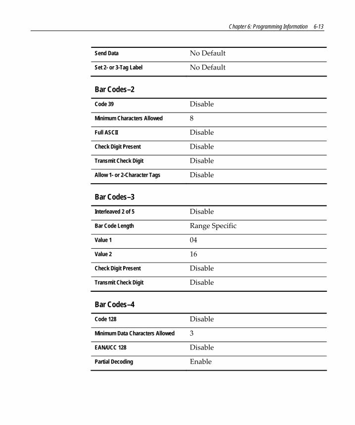
Chapter 6: Programming Information 6-13
Send Data No Default
Set 2- or 3-Tag Label No Default
Bar Codes–2
Code 39 Disable
Minimum Characters Allowed 8
Full ASCII Disable
Check Digit Present Disable
Transmit Check Digit Disable
Allow 1- or 2-Character Tags Disable
Bar Codes–3
Interleaved 2 of 5 Disable
Bar Code Length Range Specific
Value 1 04
Value 2 16
Check Digit Present Disable
Transmit Check Digit Disable
Bar Codes–4
Code 128 Disable
Minimum Data Characters Allowed 3
EAN/UCC 128 Disable
Partial Decoding Enable

6-14 Chapter 6: Programming Information
Bar Codes–5
GS1 DataBar Enable Disable
Scans Required On GS1 DataBar 14 1 Scan
UCC-128 Emulation Mode Normal Mode
Bar Codes–6
ISBN Disable
ISSN Disable
Label Identifiers
Identifier Type Default Prefix
Common Byte 1 5D
Common Byte 2 42
Bar Code Type No Default
Common Byte No Default
Unique Identifier No Default
RS-232 Parameters–1
Baud Rate 9600
Parity Odd
Stop Bits and Character Length 1 Stop Bit, 7‐Bit Length
Handshake RTS High, Wait for CTS

Chapter 6: Programming Information 6-15
RS-232 Parameters–2
BCC Options • Scanner Only – Disable • Scanner/Scale – Enable
Interface Control None
Check Digit • Enable UPC‐A • Enable EAN‐8 • Enable EAN‐13 • Disable UPC‐E
RS-232 Prefix Byte
Prefix Byte Disable
ASCII Code 02
RS-232 Terminator Byte
Terminator Byte 1 Enable
ASCII Code 03
Terminator Byte 2 Disable
RS-232 Communications Options
Message Delay 10 ms Delay
Scanner or Scanner/Scale Format No Default
Good Weigh Tone Disable

6-16 Chapter 6: Programming Information
Scale Parameters
Model Number No Default
IBM Address Address 6E set by selecting IBM 468x on Communications Protocol worksheet
Miscellaneous Parameters
Host Tone Control Disable
IBM Retransmit Control 3 Times
OCIA Price Display Enabled (This parameter is not available on Super ASIC models)
Enable/Disable of Voice Messages Enable
IBM-485 / IBM-USB Tag Data Format Hex
Dual Cable Interface
Scale Type Avery (This parameter is not available on Super ASIC models)

Chapter 6: Programming Information 6-17
Programming Tips Turn the host terminal off or disconnect all interface cables to the RealScan 75 before entering your program. Some host terminals can corrupt your program if they are running and are connected to the RealScan 75 while you are entering the program.
To exit a Specific Programming Mode without entering all the parameters, scan the Abort tag. All parameters entered are retained and the RealScan 75 returns to the Base Programming State. To save the changed parameters, you must scan the Save and Reset tag.
To exit the programming mode without saving any parameter changes, scan the Abort tag while in the Base Programming State. The RealScan 75 goes through initial startup and operates using the old program.
If you do not know how your RealScan 75 is programmed, set all parameters to default values, then enter any required changes. Do this by scanning the Default tag as the first tag after applying power to the RealScan 75. Next, scan the Programming Mode tag to enter the Base Programming State and enter your programming changes.
Note: Some parameters do not have default values and are not changed when the Default tag is scanned.

6-18 Chapter 6: Programming Information
Parameter Descriptions
Communications Protocol The Communications Protocol programming mode selects the protocol that the RealScan 75 uses to communicate with the host terminal.
Note: The factory sets the Communications Protocol according to the specifications on your order. Before changing the Communications Protocol, the RealScan 75 must contain the correct Communications Interface Board. Also, since there is no default Communications Protocol; the Default tag does not change this parameter.
Sample Program Following is an example of a completed Communications Protocol worksheet. In this example, RS‐232 is the selected protocol.
CommunicationsProtocol
1 0Protocol
5
R0064
Program Parameters
Casio Dual Cable Note: This parameter is only for Single ASIC and Dual ASIC Release 1 models – Super ASIC models do not have OCIA communications.
The Casio Dual Cable configuration uses two separate cables for the scanner and the scale. The scanner data protocol is the same as in the OCIA Non NCR protocol. The scale data protocol is the same as is used on OCIA Dual Cable scale communications (OCIA NCR Short).
Chapter 6: Programming Information 6-19
IBM Slot Scanner All models of the RealScan 75 support the IBM 468x/9x format and use the same protocol found on IBM terminals. The scanner uses terminal port 17 and the select address is set to 4A.
If your unit is a scanner/scale, the IBM address default setting is 6E, but can be programmed to 6A or 6B. The IBM terminal integrated scanner/scale driver normally uses address 6E. However, if the scanner works but the scale does not, try using the other two scale addresses.
IBM - USB The RealScan 75 can communicate to the host terminal through a USB cable. This parameter enables the IBM ‐ USB format.
NCR (RS-232) USB The RealScan 75 can communicate to the host terminal through a USB cable. This parameter enables the NCR (RS‐232) format.
Note: Two programming tags must be scanned to enable this parameter: Hex E followed by Hex 0.
OCIA NCR Dual Cable Note: This parameter is only for Single ASIC and Dual ASIC Release 1 models – Super ASIC models do not have OCIA communications.
The OCIA NCR Dual Cable configuration uses two separate cables for the scanner and scale. The data protocol is the same as in OCIA NCR Short. This dual cable communications scheme is used on older NCR terminal systems such as 2557 and 2126 systems. This format can accommodate only 5 data bits per character and supports only UPC/EAN bar code data.
OCIA NCR Long Note: This parameter is only for Single ASIC and Dual ASIC Release 1 models – Super ASIC models do not have OCIA communications.

6-20 Chapter 6: Programming Information
OCIA Long (Alternate Codes Long Format) is used on the RealScan 52 Alternate Codes Scanner and the RealScan 90 Presentation Scanner. This format originally supported only single byte commands from the host terminal due to scanner limitations. The OCIA NCR Long format sends ASCII tag data to the host terminal. Since this format supports 8 data bits, it can accommodate the alphanumeric data found in the Code 128 and Code 39 bar codes, provided the system software supports those codes. This data format cannot accommodate scale communications and is not the same as the data format used in Single Cable OCIA, even though both formats use long format OCIA hardware.
OCIA NCR Short (Datachecker) Note: This parameter is only for Single ASIC and Dual ASIC Release 1 models – Super ASIC models do not have OCIA communications.
NCR short format OCIA is the scanner only (RealScan 75‐1xxx/3xxx) protocol used in older NCR terminal systems such as 2557 and 2126 systems. Later model terminals may also use this format for scanner only configurations. If the scale is enabled (RealScan 75‐2xxx), a system using the short format OCIA protocol uses the OCIA Dual‐Cable setting as explained under OCIA Dual‐Cable. This format accommodates only 5 data bits per character and supports only UPC/EAN bar code data.
A scanner or scanner/scale that uses the Datachecker Interface should be programmed using this format. If the protocol information is lost, the scanner/scale defaults to RS‐232. It then must be reprogrammed to OCIA NCR Short.
OCIA Non-NCR Dual Cable Note: This parameter is only for Single ASIC and Dual ASIC Release 1 models – Super ASIC models do not have OCIA communications.
Chapter 6: Programming Information 6-21
Non‐NCR short format is used on some older competitive terminal systems. This format is sometimes called 6‐bit ASCII since it can accommodate only 6 data bits per character. It cannot support Code 128 or Code 39 bar code data. This format is normally not used on NCR systems.
OCIA Single Cable Note: This parameter is only for Single ASIC and Dual ASIC Release 1 models – Super ASIC models do not have OCIA communications.
The OCIA Single‐Cable scanner/scale format is the format normally used in older supermarket systems to talk to a RealScan 75 Scanner/Scale. Since this format supports 7‐bit data, it can accommodate the alphanumeric data found in the Code 128 and Code 39 bar codes, provided the system software also support those codes.
RS-232 RS‐232 is used to connect the scanner or scanner/scale to almost any RS‐232 type of communications device. This protocol uses 7‐bit ASCII to send tag and scale data to the device.
TEC Dual Cable Note: This parameter is only for Single ASIC and Dual ASIC Release 1 models – Super ASIC models do not have OCIA communications.
The TEC 4‐Bit Parallel protocol is used when connecting the RealScan 75 to a TEC M‐XXXX host terminal. This configuration uses two cables. The scanner uses an OCIA interface and the scale uses a 4‐bit parallel interface.

6-22 Chapter 6: Programming Information
Good Read Tone The Good Read Tone programming mode selects the parameters for sounding a tone each time the RealScan 75 Scanner/Scale successfully reads a bar code. It also controls the volume of the Not‐On‐File tone. This mode contains five shortcuts: A, B, C, D, and E. After entering this programming mode, you normally go directly to a specific parameter by scanning the appropriate shortcut Hex tag. This eliminates the need to enter all parameters when only one needs changing.
Sample Program Following is an example of a completed Good Read Tone programming worksheet. In this example, the only selection that can be made beforehand is the tone on/off, which is selected to be on. The other adjustments are selected by listening to the tone as you repeatedly scan the appropriate Hex tag.
Your Program
1Frequency
Tone
B
ToneLength
C
ToneVolume
D
1 1 B C D* * *
Not-On-File ToneVolume
E
E*
* Scan Hex tag repeatedly for desired setting.
ToneOn/Off
A
B052
Good Read Tone
Program Parameters
Not-On-File Tone Volume The Hex E tag permits selection of the volume of the Not‐On‐File tone by listening to it as it repeatedly scans the Hex E tag. The new tone sounds for two seconds. End this mode by scanning the End tag or another valid Hex tag.

Chapter 6: Programming Information 6-23
Tone Frequency (Hertz) The Hex B tag permits setting of frequency of the Good Read tone by listening to it. Each time the Hex B tag is scanned, the tone increments one unit. After reaching the highest frequency (1250 Hertz), the sequence starts over with the lowest frequency (524 Hertz). End this mode by scanning the End tag or another valid Hex tag.
Tone Length (Milliseconds) The Hex C tag permits setting of length of the Good Read tone by listening to it. Each time the Hex C tag is scanned, the tone length changes from a minimum of 25 milliseconds to a maximum of 250, and then back again. End this mode by scanning the End tag or another valid Hex tag.
Tone On/Off The Hex A tag selects the Tone On/Off programming parameter, which offers two options, On and Off. The Hex 0 tag turns the Good Read tone off and the Hex 1 tag turns the Good Read tone on. The default is to turn the Good Read tone on.
Tone Volume The Hex D tag permits selection of the volume of the Good Read tone by listening to it as it repeatedly scans the Hex D tag. End this mode by scanning the End tag or another valid Hex tag.
Timers The Timers programming mode controls the two RealScan 75 timers: Lockout Time and Active Time.
Sample Program Following is an example of a completed Timer programming worksheet. In this example the time‐outs are programmed for the following.

6-24 Chapter 6: Programming Information
• Lockout Time – 900 milliseconds • Restart Lockout Timer – off • Active Time – 30 minutes
Program Parameters
11814
A
LockoutTime
3
B
TimerRestart
0
C
ActiveTime
2Timers
1 2
Active Time (Minutes) You can program specific lengths of time that your RealScan 75 stays on after the last good read. There are four options in the Active Time parameter: no shut down, shut down after 15 minutes, shut down after 30 minutes, and shut down after 60 minutes. Select these times using the Hex 0 through Hex 3 tags, respectively. The default time is 15 minutes. Selecting No Shut Down results in the scanner/scale being active all the time.
Note: NCR suggests that you do not set the Active Time parameter to 0. Leaving the laser light on all the time reduces its life expectance.
Restart Lockout Timer The Restart Lockout Timer parameter controls restarting the lockout timer each time the RealScan 75 reads the same bar code. Turning on the Restart Lockout Timer option has the following effect. After reading a bar code, if the bar code moves out of the scan pattern and then back into the scan pattern before the lockout timer times out, the lockout timer restarts. The Hex 0 tag turns off this option and the Hex 1 tag turns it on. The default is off.

Chapter 6: Programming Information 6-25
Lockout Time (Milliseconds) The lockout timer prevents the scanner/scale from repeatedly reading the same bar code. After reading a bar code, it must be removed from the scan pattern and the time programmed in the lockout timer must elapse before the scanner/scale can read the same bar code again. The Lockout Time parameter selects the lockout time.
There are 9 specific times ranging from 350 milliseconds to 1500 milliseconds. Select these times using the Hex 0 through Hex 8 tags. The default time is 900 milliseconds.
Bar Codes–1 The Bar Codes 1 programming mode contains programming parameters for UPC/EAN bar codes.
Sample Program Following is an example of a completed Bar Codes 1 programming worksheet. In this example the UPC/EAN bar codes are programmed for the following.
• UPC/EAN – enabled • Version D tags – None (Always None on Single ASIC and Dual
ASIC models, not available on Super ASIC models) • Extend UPC‐A to EAN‐13 – disabled • Extend UPC‐E to UPC‐A – disabled • Periodical Codes – enabled • Periodical Code Extensions – 2‐ and 5‐digit extensions • Send data – as decoded

6-26 Chapter 6: Programming Information
Refer toProgram Entryon Page A-2
Your Program
0Version
D
B
0ExtendUPC-A
C
0ExtendUPC-E
D
1Periodical
Codes
E
2Periodical
CodeExtension
0SendData
Bar Codes - 1
1 3 1UPC/EAN
A
B055
Program Parameters
Extend UPC-A To EAN-13 The Extend UPC‐A to EAN‐13 parameter determines whether to pad the tag data, changing 12‐digit UPC tags to 13‐Character EAN tags. The program does this by putting a zero (0) at the front of the tag data. Scan the Hex 0 tag to disable this option or the Hex 1 tag to enable it. The default is Disable and scanning a valid Hex tag ends the input for this parameter option.
Extend UPC-E To UPC-A The Extend UPC‐E to UPC‐A parameter determines whether to pad the tag data, changing ‐digit truncated UPC tags to 12‐Character UPC‐A tags. Scan the Hex 0 tag to disable this option or the Hex 1 tag to enable it. The default is Disable and scanning a valid Hex tag ends the input for this parameter option.
Periodical Codes The Periodical Codes parameter controls the processing of Periodical Codes. Disable Periodical Codes by scanning the Hex 0 tag and enable them by scanning the Hex 1 tag. The default is to disable Periodical Codes.
If you choose to disable Periodical Codes, there are no other entries allowed for this parameter. Scanning the Hex 0 tag also causes the scanner/scale to go back to the Base Programming State. However, if you enable Periodical Codes, you must also program the Periodical Code Extension and Send Data parameters.

Chapter 6: Programming Information 6-27
Note: Use of optional add‐on bar codes may require additional programming. Refer to Special Programming, Early Beep Disable and Terminal Coupon Interface Parameters in Chapter 6: Programming.
Periodical Code Extension The Periodical Code Extension parameter has three selections: 2‐digit extension only, 5‐digit extension only, and either 2‐ or 5‐digit extensions. Scan the Hex 0 tag for 2‐digit extension only, the Hex 1 tag for 5‐digit extension only, or the Hex 2 tag for both the 2‐ and 5‐digit extension. The default is 2‐ and 5‐digit extensions and scanning a valid Hex tag causes the program to go to the next parameter option.
Send Data The Send Data parameter has three selections: Data As Decoded, All Data If Periodical Code Present, and CF Hex If Periodical Data Not Decoded. If you scan the Hex 0 tag, the data is sent as decoded, whether or not there are extension digits. If you scan the Hex 1 tag, the bar code data is sent only if the periodical code is present. If you scan the Hex 2 tag, a hexadecimal CF is sent as the extension if the scanner/scale could not read a 2‐ or 5‐digit code. The default is Data as Decoded and scanning a valid Hex tag causes the program to go to the Base Programming State.
UPC/EAN The UPC/EAN parameter controls reading UPC/EAN bar codes. Disable reading UPC/EAN bar codes by scanning the Hex 0 tag and enable reading by scanning the Hex 1 tag. The default is to enable reading.
If you choose to disable reading UPC/EAN bar codes, there are no other entries allowed for this parameter. However, if you enable reading UPC/EAN bar codes, you can program the remaining parameters.

6-28 Chapter 6: Programming Information
Version D The Version D parameter (Single ASIC and Dual ASIC models) permitted you to enable or disable reading UPC Version D bar codes. However, this function is not used so the only option available is None. The default is None.
Note: This parameter is not available on the Super ASIC models.
Bar Codes–2 The Bar Codes 2 programming mode contains programming parameters for Code 39.
Sample Program Following is an example of a completed Bar Codes 2 programming worksheet. In this example, Code 39 is enabled with the following options.
• Code 39 – enabled • Minimum Characters Allowed – 5 • Full ASCII – disabled • Check Digit Present – enabled • Transmit Check Digit – enabled • Allow One‐ or Two‐Character Tags – disabled

Chapter 6: Programming Information 6-29
Code 39A 0Disable
1Enable
MinimumCharactersAllowed
B 82 - F Default
Full ASCIIC 0Disable
1Enable
Check DigitPresent
D 0Disable
1Enable
TransmitCheck Digit
E 0Disable
1Enable
Allow 1- or2-CharacterTags
F 0Disable
1Enable
Your Program
24174
Code 39
A
Bar Codes - 2
1 4
MinimumCharacters
Allowed
B
FullASCII
C
Check DigitPresent
D
TransmitCheck Digit
E
Allow 1-or
2-CharacterTags
F
For SuperASIC scanners,continue to option F even if Check Digit Present Disableis chosen.
Note:

6-30 Chapter 6: Programming Information
Program Parameters
Allow 1- Or 2-Character Tags The Allow One‐ or Two‐Character Tags parameter selects whether or not to permit the scanner to read a one‐ or two‐character Code 39 label. If your application does not require that the scanner read a one‐ or two‐character Code 39 label, scan the Hex 0 tag to disable this option. If your application requires this capability, scan the Hex 1 tag to enable it. The default is to disable reading a one‐ or two‐character Code 39 label.
Code 39 The Code 39 parameter controls reading Code 39 bar codes. Disable reading Code 39 bar codes by scanning the Hex 0 tag and enable reading by scanning the Hex 1 tag. The default is to disable reading.
If you choose to disable reading Code 39 bar codes, there are no other entries allowed for this parameter. However, if you enable reading Code 39 bar codes, you can program the rest of the parameters.
Check Digit Present The Check Digit Present parameter permits you to determine if the bar code must contain a correct check digit to be identified as valid. If this function is enabled, the bar code is ignored if a check digit is not present. Scan the Hex 0 tag to disable this option, or the Hex 1 tag to enable it. Disable is the default.
Full ASCII Code 39 permits full ASCII capability by encoding the additional characters. Disable this function by scanning the Hex 0 tag, and scan the Hex 1 tag to enable this function. Disable is the default.

Chapter 6: Programming Information 6-31
Minimum Characters Allowed The Minimum Characters Allowed parameter defines how many characters in a bar code must be read the same by two separate scans before determining a valid read has occurred. You should set this option to the number of characters in a typical tag. This assures that the scanner/scale reads typical tags with at least two complete good scans before sending the tag data to the host terminal.
There are 15 selections for this parameter option (2 through 16 characters). Scan the proper Hex tag (Hex 2 through Hex F) to enter your selection. The default is 8 characters.
Transmit Check Digit The Transmit Check Digit parameter selects whether to send the check digit to the host terminal. Scan the Hex 0 tag to disable this option, or the Hex 1 tag to enable it. The default is to disable sending the check digit.

6-32 Chapter 6: Programming Information
Bar Codes–3 The Bar Codes 3 programming mode contains programming parameters for Interleaved 2 of 5.
22765
A
B
Interleaved2 of 5
Bar Code Length
C Check DigitPresent
D
10Disable Enable
0 - 5
10Range Check
SpecificCheck
CharacterMinimum
CharacterMaximum
10Disable Enable
10Disable Enable
0 - 5 0 - 9
0 - 9
TransmitCheck Digit
Character 1 Character 2
Character 1 Character 2 Default
Default
1 6
0 8
Value 1
Value 2
Your Program A
Interleaved2 of 5
Bar Codes - 3
1 5
Check DigitPresent
C
TransmitCheck Digit
D
Value 1 Value 2Bar CodeLength
B
Starting April 2005 Release of SuperAsic firmware (497-0439869), inputting an ODD or HEX number for tag length, whether inputting values for Specific Length, Range of values, and Minimum or Maximum values results in a Program Tag Error.
Note:

Chapter 6: Programming Information 6-33
Program Parameters
Bar Code Length The Bar Code Length parameter selects the method for determining if an Interleaved 2 of 5 bar code is a valid length. The Range Check method identifies a length range by specifying the minimum and maximum number of characters. The Specific Check method identifies two specific bar code lengths by specifying the number of characters in each. With this option, the number of characters in all Interleaved 2 of 5 bar codes must be one of the two numbers. Scan the Hex 0 tag to use the Range Check method, scan the Hex 1 tag to use the Specific Check method. The default is the Range Check method.
Check Digit Present The Check Digit Present parameter permits you to determine if the bar code must contain a correct check digit to be identified as valid. If this function is enabled, the bar code is ignored if a check digit is not present. Scan the Hex 0 tag to disable this option, or the Hex 1 tag to enable it. Disable is the default.
Interleaved 2 of 5 The Interleaved 2 of 5 parameter controls reading Interleaved 2 of 5 bar codes. Disable reading Interleaved 2 of 5 bar codes by scanning the Hex 0 tag and enable reading by scanning the Hex 1 tag. The default is to disable reading.
If you choose to disable reading Interleaved 2 of 5 bar codes, there are no other entries allowed for this parameter. However, if you enable reading Interleaved 2 of 5 bar codes, you can program the remaining parameters.
Transmit Check Digit The Transmit Check Digit parameter selects whether to send the check digit to the host terminal. Scan the Hex 0 tag to disable this option, or the Hex 1 tag to enable it. The default is to disable sending the check digit.

6-34 Chapter 6: Programming Information
Value 1 and 2 The Value 1 and Value 2 parameter specifies the valid Interleaved 2 of 5 bar code lengths. Use this option with the Bar Code Length parameter option described in Bar Code Length. If you select the Range Check method, Value 1 specifies the minimum number of characters in a valid Interleaved 2 of 5 bar code and Value 2 specifies the maximum number of characters. If you select the Specific Check method, Value 1 contains one specific number of characters and Value 2 contains another.
Accepted values for Value 1 and Value 2 are 04 to 58 readable characters. The number of readable characters must be an even number; if you specify an odd number, it returns a Program Tag Error. Each value is input using two Hex tags. The first can be Hex 0 through Hex 5 and the second can be Hex 0 through Hex 9. The default for Value 1 is 08 and for Value 2 is 16.

Chapter 6: Programming Information 6-35
Bar Codes–4 The Bar Codes 4 programming mode contains programming parameters for Code 128 bar codes.
Sample Program Following is an example of a completed Bar Codes 4 programming worksheet. In this example the Code 128 bar codes are programmed for the following.
• Code 128 – enabled • Minimum Data Characters Allowed – 3 • UCC 128 – disabled
22766
Code 128A 0Disable
1Enable
Minimum DataCharactersAllowed
B 1 2 3 4 5
EAN/UCC 128C 0Disable
1Enable
Your Program
Bar Codes - 4
1 7
A
Code 128
B
MinimumData
CharactersAllowed
C
UCC 128
Partial Decoding
F 0Disable
1Enable
F
PartialDecoding

6-36 Chapter 6: Programming Information
Program Parameters
Code 128 The Code 128 parameter contains two selections: Disable and Enable. Disable reading Code 128 bar codes by scanning the Hex 0 tag and enable reading by scanning the Hex 1 tag. However, selecting the disable option does not prevent reading the programming tags that are Code 128. The default is to disable reading Code 128 bar codes.
Minimum Data Characters Allowed The Minimum Data Characters Allowed refers to the Code 128 characters on a numeric‐only Code 128 symbol. For example, given a numeric‐only Code 128 symbol of 12 34 56 78, the Minimum Data Characters Allowed would be 4; each Code 128 character is composed of two numeric data characters. Enter your selection by scanning the appropriate hex tag (Hex 1 through Hex 5). The default is three.
UCC 128 The UCC 128 option refers to the Uniform Code Council Code 128 Data Formatter Start Code. Scan the Hex 0 tag to disable this function, or the Hex 1 tag to enable it. The default is disable.
Partial Decoding The Partial Decoding parameter allows the scanner to read damaged or poorly‐printed Code 128 tags by putting together separate pieces (partials) of barcode data. Scan Hex 0 to disable Partial Decoding or Hex 1 (default) to enable it.
Tone This parameter permits you to enable or disable the Code 128 tone. Scan Hex 0 to disable the tone (default) or Hex 1 to enable it.

Chapter 6: Programming Information 6-37
Tone Length The Tone Length parameter permits you to set the length of the Code 128 tone. Set this parameter by scanning the appropriate Hex tag (Hex 0 to Hex F). Each Hex tag is incremented by 15 milliseconds. For example, Hex 0 is 0 milliseconds, Hex 1 is 15 milliseconds, Hex 2 is 30 milliseconds, Hex 3 is 45 milliseconds, and so forth. The default Code 128 Tone Length is 75 milliseconds (Hex 5).
Tone Frequency The Tone Frequency parameter permits you to set the frequency of the Code 128 tone. Set this parameter by scanning the appropriate Hex tag (Hex 0 to Hex 7). The default Code 128 Tone Frequency is 947 Hertz (Hex 4).
Scans Required This parameter sets the number of scans required to read a Code 128 bar code. Increasing the number of scans can improve reading nominal bar codes. There are four settings: 1 scan, 2 scans, 3 scans, and 4 scans. The default is 1 scan. Set this parameter by scanning the appropriate Hex tag (Hex 1 to Hex 4).
Overlap Characters This parameter sets the minimum number of Code 128 characters which each segment must contain when putting partial tag segments together. There are four settings: 1 overlap character (Hex 1), 2 overlap characters (Hex 2) (default), 3 overlap characters (Hex 3), and 4 overlap characters (Hex 4). Set this parameter by scanning the appropriate Hex tag (Hex 1 to Hex 4).
Minimum Segment Size This parameter sets the number of Code 128 characters which are required for the minimum length of the partial tag segments being put together. Set this parameter by scanning the appropriate Hex tag (Hex 2 to Hex 9). The default is Hex 5.
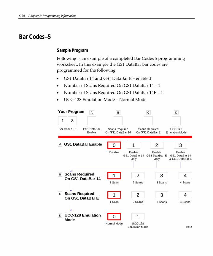
6-38 Chapter 6: Programming Information
Bar Codes–5
Sample Program Following is an example of a completed Bar Codes 5 programming worksheet. In this example the GS1 DataBar bar codes are programmed for the following.
• GS1 DataBar 14 and GS1 DataBar E – enabled • Number of Scans Required On GS1 DataBar 14 – 1 • Number of Scans Required On GS1 DataBar 14E – 1 • UCC‐128 Emulation Mode – Normal Mode
24952
GS1 DataBar Enable
Scans RequiredOn GS1 DataBar 14
B
A
Disable
0Enable
GS1 DataBar 14Only
1
1 Scan
12 Scans
23 Scans
34 Scans
4
1 8
Your Program
Bar Codes - 5 GS1 DataBarEnable
A
Enable GS1 DataBar E
Only
2Enable
GS1 DataBar 14& GS1 DataBar E
3
Scans RequiredOn GS1 DataBar E
C
1 Scan
12 Scans
23 Scans
34 Scans
4
UCC-128 EmulationMode
D
Normal Mode
0UCC-128
Emulation Mode
1
B
Scans RequiredOn GS1 DataBar 14
C
Scans RequiredOn GS1 DataBar E
D
UCC-128Emulation Mode

Chapter 6: Programming Information 6-39
Program Parameters
GS1 DataBar Enable This parameter contains 4 selections. Disable reading GS1 DataBar bar codes by scanning the Hex 0 programming tag. Reading either or both GS1 DataBar 14 and GS1 DataBar E bar codes is enabled with this parameter. The default is disable.
• Read GS1 DataBar 14 only – Scan the Hex 1 programming tag. • Read GS1 DataBar E only – Scan the Hex 2 programming tag. • Read both GS1 DataBar 14 and GS1 DataBar E – Scan the Hex 3
programming tag.
Scans Required on GS1 DataBar 14 This parameter sets the number of scans required to read a GS1 DataBar 14 bar code. Increasing the number of scans can improve reading nominal bar codes. There are four settings: 1 scan, 2 scans, 3 scans, and 4 scans. The default is 1 scan. Set this parameter by scanning the appropriate programming tag, Hex 1 through Hex 4.
Scans Required on GS1 DataBar E This parameter sets the number of scans required to read a GS1 DataBar E bar code. Increasing the number of scans can improve reading nominal bar codes. There are four settings: 1 scan, 2 scans, 3 scans, and 4 scans. The default is 1 scan. Set this parameter by scanning the appropriate programming tag, Hex 1 through Hex 4.
UCC-128 Emulation Mode The UCC‐128 Emulation Mode refers to the Uniform Code Council Code 128 Data Formatter Start Code. Two choices are available for this parameter. Scan the Hex 0 programming tag for normal mode or the Hex 1 programming tag to enable UCC‐128 Emulation. The default is Normal Mode.

6-40 Chapter 6: Programming Information
Bar Codes–6 ISBN (International Standard Book Number) is a unique ten‐digit number assigned to every printed book. These 13‐digit numbers are used internationally.
As of January 1, 2007, all book and book‐related products must carry 13‐digit ISBNs. All 10‐digit ISBNs in circulation will have the 3‐digit EAN prefix ʺ978ʺ added (which currently represents the book industry). This 13‐digit ISBN is already represented, and will be identical, to current EAN bar codes carrying ISBN with the ʺ978ʺ prefix. Every ISBN registered will automatically be converted to 13‐digits. The EAN prefix ʺ979ʺ cannot be used on existing 10‐digit ISBNs.
ISSN (International Standard Serial Number) is a unique eight‐digit number assigned to all serial publications, including electronic ones. Serial publications include newspapers, newsletters, annual reports, yearbooks, directories, and journals. It is the publicationsʹ eqvivalent to the ISBN, and like the ISBN, these numbers are used internationally.
ISBN-10 and ISBN-13 An EAN‐13 bar code having a prefix of 978 is considered as an ISBN‐10 tag. With the ISBN feature enabled, this tag outputs the ISBN‐10 equivalent instead of EAN‐13.
An ISBN‐13 is exactly the same as an EAN‐13 tag. It may have a prefix of either 978 or 979. With the ISBN feature enabled, the ISBN tag with a prefix of 978 is sent in its ISBN‐10 equivalent while the tag with the prefix of 979 is sent as an EAN‐13. The default setting for this option is 2(Disabled).

Chapter 6: Programming Information 6-41
ISSN An EAN‐13 tag with a prefix of 977 is an ISSN tag. With the ISSN feature enabled, scanning this tag automatically outputs the ISSN equivalent of the EAN‐13 tag. The default setting for this option is 9(Disabled).
23484
Your Program
Disable
2Enable
ISBN 3
1 9
Bar Codes - 6 ISBN
1. If the tag is an ISBN tag and it is enabled, the output will be the 10-digit ISBN. The 10th digit will be replaced by the ISBN checkdigit (modulo 11 with weights 10 to 2).2. If the tag is an ISSN tag and it is enabled, the output will be the 8-digit ISSN. The 8th digit will be replaced by the ISSN checkdigit (modulo 11 with weights 8 to 2).3. The LabelID used is still the LabelID for EAN-13.
For SuperASIC firmware versions (below) and upcoming releases:Programmed Firmware Chip (497-0443786) Flash MEDIA (497-0443785)
Note:Enable
8Disable
ISSN 9
ISSN
Note:

6-42 Chapter 6: Programming Information
Label Identifiers The Label Identifiers programming mode selects the parameters for adding label identifiers to communication messages. If used with RS‐232 or OCIA NCR Long or OCIA NCR Short when reading UPC Version D bar codes, the identifiers go before the bar code data. Label identifiers for the other modes of communication are determined by the firmware and are not programmable.
Note: OCIA communications is not supported on Super Asic models. This applies to Single ASIC and Dual ASIC Release 1 models only.
Sample Program Following is an example of a completed Label Identifiers programming worksheet. This example shows the following programmed selections.
• Identifier Type – Unique Prefix added to all bar code data messages • Common Byte 1 – 5B ([) • Common Byte 2 – 42 (B) • Bar Code Type UPC‐A • Common Bytes – Common Byte 1 • Unique Identifier – 48 (H) • Bar Code Type Code 39 • Common Bytes – No Common Bytes • Unique Identifier – 41 (A) • Bar Code Type Code 128 • Common Bytes – Common Byte 1 • Unique Identifier – 43 (C)

Chapter 6: Programming Information 6-43
Identifier TypeDefault Prefix
24953
A
Common Byte 1B
Common Byte 2C
Bar Code TypeD
Common Byte
Unique Identifier
0 - 7 5 Default
Hex Character(ASCII Code Chart)
0 - FHex Character
(ASCII Code Chart)
0 - 7 Default
Hex Character(ASCII Code Chart)
0 - FHex Character
(ASCII Code Chart)
None Unique Prefix
0 2 3
UPC-A
0UPC-E
2EAN-8
3EAN-13
4
Code 39
5Code 128
6Interleaved
2 of 5
7
None
0Common Byte 1
1Common Byte 2
2Both
Common Bytes
3
10 - 7Hex Character
(ASCII Code Chart)
0 - FHex Character
(ASCII Code Chart)
Common Byte andUnique Identifier Defaults varyaccording to Bar Code Type
D
4 2
GS1DataBar 14
8 9GS1 DataBar
Expanded
AIM IDOn GS1DataBar
4
UPC-D
1
1 6Identifier
TypeCommon
Byte 1Common
Byte 2
CommonByte
Unique IdentifierBar CodeType
Your Program A B C D
Label Identifiers

6-44 Chapter 6: Programming Information
Program Parameters
Bar Code Type The Bar Code Type parameter selects the bar code type for entering its associated label identifier information. After entering a Bar Code Type, enter the Common Byte and Unique Identifier. This procedure repeats until the label identifiers are specified for each bar code type. Scan the Hex 0 through Hex 9 tag to enter the appropriate Bar Code Type. Since you must select each of these individually for your application, there is no default for this parameter.
Common Byte The Common Byte parameter selects which common bytes, if any, to add to the bar code data message. Each entry is unique to the previously specified Bar Code Type. Scan the Hex 0 tag for no Common Bytes, the Hex 1 tag for Common Byte 1, the Hex 2 tag for Common Byte 2, the Hex 3 tag for both Common Bytes, the Hex 4 tag for AIM Unique ID, or the Hex 5 tag for No Common Bytes and No Unique Identifiers. The default for this parameter uses Common Byte 2 as a suffix for Code 39, Code 128, and Interleaved 2 of 5 bar code data. UPC and EAN bar codes do not use Common Bytes.
Common Byte 1 and Common Byte 2 The Common Byte 1 and Common Byte 2 parameters permit you to specify the data sent to the host terminal in the Common Byte fields. Enter this information as two Hex characters for each Common Byte.
Note: Refer to the ASCII Code Chart for the Hex Characters; however, values of 20 to 7E are recommended. Do not use the same characters as the Terminator Byte or the message may terminate too soon. Also, a Common Byte cannot be 00.
If you are not going to use a Common Byte, you can scan any Hex tag twice except Hex 0 or the Terminator Byte value. The default for Common Byte 1 is 5D (ASCII ]) and the default for Common Byte 2 is 42 (ASCII B). You must scan four tags to go to the next parameter.

Chapter 6: Programming Information 6-45
Identifier Type The Identifier Type parameter defines the type and placement of label identifiers. You can select default identifiers that prefix the message data, unique prefix identifiers, or no identifiers.
Select the Identifier Type parameter by scanning the appropriate tag (Hex 0, Hex 2, or Hex 3). If you select default identifiers, you do not enter any other parameter in this programming mode. The factory set default is Default Prefix.
Default Prefix Scan the Hex 0 tag to use the default prefix. The default label identifiers vary depending on the type of bar code read. Following are the default identifiers for each bar code type.
• UPC‐A 41H NS X1 X2 X3 X4 X5 X6 X7 X8 X9 X10 CK
• UPC‐E 45H 30H X1 X2 X3 X4 X5 X6
• EAN‐8 46H 46H X1 X2 X3 X4 X5 X6 X7 CK
• EAN‐13 46H X1 X2 X3 X4 X5 X6 X7 X8 X9 X10 X11 X12 CK
• Code 39 42H 31H X1 X2 X3 X4 X5 X6 X7 X8 X9 X10 X11 X12 X13 X14 X15 X16 X17 X18 X19 X20 X21 X22 X23 X24 X25 X26 X27 X28 X29 CK
• Code 128 42H 33H X1 X2 X3 X4 X5 X6 X7 X8 X9 X10 X11 X12 X13 X14 X15 X16 X17 X18 X19 X20 X21 X22 X23 X24 X25 X26 X27 X28 X29 CK
• Interleaved 2 of 5 42H 32H X1 X2 X3 X4 X5 X6 X7 X8 X9 X10 X11 X12 X13 X14 X15 X16 X17 X18 X19 X20 X21 X22 X23 X24 X25 X26 X27 X28 X29 CK

6-46 Chapter 6: Programming Information
• GS1 DataBar‐14
5D 65H 30H X0 X1 X0 X0 X0 X1 X2 X3 X4 X5 X6 X7 X8 X9 X10 • GS1 DataBar‐E
5D 65H 30H X9 X5 X0 X1 X2 X3 X4 X5 X6 X7 X8 X9 X10 None Scan the Hex 2 tag to select none. No label identifiers are added to the message data.
Unique Prefix To use a unique prefix, scan the Hex 3. A Unique Identifier is associated with each bar code type. Also, you may use one, two, or no Common Bytes. The figure shows the possible message formats when using a unique prefix. The formats do not show other elements programmed in the other RS‐232 programming modes.
Unique Identifier The Unique Identifier parameter permits you to specify the data sent to the host terminal in the Unique Identifier field. Each entry is unique to the previously specified Bar Code Type. Enter this data as two Hex characters using recommended values of 20 to 7E (Refer to the ASCII Code Chart). The following are the default values.
• UPC‐A 41 (ASCII A)
• UPC‐E 45 (ASCII E)
• EAN‐8 46 (ASCII F)
• EAN‐13 47 (ASCII G)

Chapter 6: Programming Information 6-47
• Code 39 31 (ASCII 1)
• Code 128 33 (ASCII 3)
• Interleaved 2 of 5 32 (ASCII 2)
• GS1 DataBar‐14 65 (ASCII e)
• GS1 DataBar‐E 65 (ASCII e)
Note: If you use the same characters as in the Terminator Byte, the message may terminate too soon.
RS-232 Parameters–1 The RS‐232 Parameters 1 programming mode contains four of the parameters required for RS‐232 communications. From this programming mode you can select the Baud Rate, Parity, Stop Bits and Character Length, and Handshake Options.
Sample Program Following is an example of a completed RS‐232 Parameters 1 programming worksheet. In this example the following are selected.
• Baud Rate – 9600 Baud • Parity – Even • Stop Bits and Character Length – 1 stop bit and 8 data bit character
length • Handshake – Raise RTS and Wait For CTS

6-48 Chapter 6: Programming Information
22772
Baud RateA 0300
1600
21200
32400
44800
59600
619200
ParityB
Stop BitsAndCharacterLength
C
HandshakeD
0Odd
1Even
4None
01 Stop Bit
7-Bit Character
11 Stop Bit
8-Bit Character
22 Stop Bits
7-Bit Character
32 Stop Bits
8-Bit Character
0RTS Low
Ignore CTS
1RTS High
Ignore CTS
2Raise RTSWait For
CTS
3Raise RTSIgnore CTS
4RTS LowWait For
CTS
5RTS HighWait For
CTS
Your Program
BaudRate
A
RS-232Parameters - 1
2 0
Parity
B
Stop BitsAnd
CharacterLength
C
Handshake
D
Program Parameters
Baud Rate The Baud Rate parameter contains seven selections: 300 Baud, 600 Baud, 1200 Baud, 2400 Baud, 4800 Baud, 9600 Baud, and 19200 Baud. Scan the appropriate Hex 0 through Hex 6 tag to set the desired Baud rate. The default is 9600 Baud.

Chapter 6: Programming Information 6-49
Handshake The Handshake parameter contains six selections. When considering these, note that the scanner/scale controls only RTS, it can monitor CTS. The following list identifies each Handshake option.
• RTS is always low, CTS is ignored (Hex 0 tag). • RTS is always high, CTS is ignored (Hex 1 tag). • Scanner/scale raises RTS and waits for CTS to go high before
transmitting (Hex 2 tag). • Scanner/scale raises RTS before transmitting and ignores the state
of CTS (Hex 3 tag). • RTS is always low and scanner/scale waits for CTS to go high
before transmitting (Hex 4 tag). • RTS is always high and scanner/scale waits for CTS to go high
before transmitting (Hex 5 tag). Scan the appropriate Hex 0 through Hex 5 tag to set the Handshake option. The default is RTS High Wait for CTS.
Parity The Parity parameter contains three selections: Odd, Even, and None. For 7‐bit characters, bit 8 is the parity bit; for 8‐bit characters, bit 9 is the parity bit. Choosing no parity and 7‐bit character length causes the scanner/scale to send two stop bits; the scanner/scale must also receive two stop bits. Scan the appropriate Hex 0, Hex 1, or Hex 4 tag to select the desired Parity. The default is Odd.
When you apply power to a RealScan 75‐2xxx/8xxx, the reset function checks the RS‐232 Communications Parity programming. If the selection is None, it is ignored and Odd parity is used. If Odd or Even is selected, that selection is used.

6-50 Chapter 6: Programming Information
Stop Bits and Character Length The Stop Bits and Character Length parameter contains four selections: 1 Stop Bit and 7‐Bit Character Length, 1 Stop Bit and 8‐Bit Character Length, 2 Stop Bits and 7‐Bit Character Length, and 2 Stop Bits and 8‐Bit Character Length. Choosing no parity and 7‐Bit Character Length causes the scanner/scale to send two stop bits; the scanner/scale must also receive two stop bits. If you select 8‐Bit Character length and parity, only one stop bit is sent. Scan the appropriate Hex 0 through Hex 3 tag to set the Stop Bits and Character Length. The default is 1 Stop Bit and 7‐Bit Character Length.
RS-232 Parameters–2 The RS‐232 Parameters 2 programming mode contains some of the parameters required for RS‐232 communications. From this mode you can select BCC Options, Interface Control, and Check Digit.
Sample Program Following is an example of a completed RS‐232 Parameters 2 programming worksheet. This example shows the following program selections.
• BCC Option – enabled • Interface Control – ACK/NAK • Check Digit – enable UPC‐A, UPC‐E, EAN‐8, and EAN‐13
2 1
RS-232Parameters - 2
1BCC
Options
A
1
ControlInterface
B
3C
CheckDigit
R0146

Chapter 6: Programming Information 6-51
Program Parameters
BCC Options The BCC Option parameter permits you to enable or disable the use of BCC at the end of a message. When enabled, the BCC is the last character sent and is the Exclusive OR of each byte sent prior to the BCC, except the prefix byte. Scan the Hex 0 tag to disable the BCC Option, or scan the Hex 1 tag to enable it. The default is disable for Scanner only models and enable for Scanner/Scale models.
Check Digit The Check Digit parameter permits you to control the transmission of UPC‐A, UPC‐E, EAN‐8, and EAN‐13 check digits. Scan the appropriate Hex 0 through Hex 3 tags to enable or disable UPC‐A, UPC‐E, EAN‐8, and EAN‐13 check digits. The default is enable UPC‐A, EAN‐8, and EAN‐13 and disable UPC‐E.
Note: Although this is an RS‐232 Parameters worksheet, the Check Digit parameter also applies to UPC‐E when using OCIA communications. This applies only to Single ASIC and Dual ASIC Release 1 models – Super ASIC models do not support OCIA communications.
Interface Control The Interface Control parameter permits you to select how to control the transfer of data between the scanner/scale and the host terminal. The options are None, enable ACK/NAK, enable XOn/XOff, and enable both ACK/NAK and XOn/XOff.

6-52 Chapter 6: Programming Information
If you enable ACK/NAK, each message sent to the host terminal must be acknowledged before sending the next message. Receiving the message properly causes an ACK to be sent, and if there are any errors, a NAK is sent instead and the scanner/scale sends the message again. Also, any valid message other than NAK or XOn/XOff, if enabled, serves as an ACK as long as the message from the scanner/scale is completed before the host terminal starts sending the valid message to the scanner/scale.
An XOff message turns the scanner transmitter off until the scanner/scale receives an XOn message. An XOn message can be received at any time. If the scanner/scale is sending a message when it receives an XOff, since these messages can be received any time, data transmission stops after sending the current byte. When the scanner/scale receives the next XOn it sends the remainder of the message. The scanner/scale does not acknowledge XOff and XOn messages with ACK or NAK messages.
You select the interface by scanning the appropriate Hex 0 through Hex 3 tag. The default is None.
RS-232 Prefix Byte The RS‐232 Prefix Byte programming mode controls the use of prefix bytes. If you use an RS‐232 Prefix Byte, it is the leading character in each message sent to the host terminal. Following it is the message data.
Sample Program Following is an example of a completed RS‐232 Prefix Byte programming worksheet. This example shows the Prefix Byte enabled, and ASCII code STX (02 Hex) transmits as the leading character of each message sent to the host terminal.
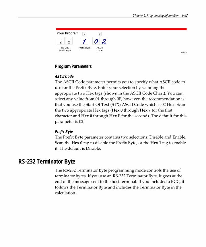
Chapter 6: Programming Information 6-53
R0074
2 2
Your Program
RS-232Prefix Byte
Prefix Byte
A
ASCIICode
B
Program Parameters
ASCII Code The ASCII Code parameter permits you to specify what ASCII code to use for the Prefix Byte. Enter your selection by scanning the appropriate two Hex tags (shown in the ASCII Code Chart). You can select any value from 01 through 0F; however, the recommendation is that you use the Start Of Text (STX) ASCII Code which is 02 Hex. Scan the two appropriate Hex tags (Hex 0 through Hex 7 for the first character and Hex 0 through Hex F for the second). The default for this parameter is 02.
Prefix Byte The Prefix Byte parameter contains two selections: Disable and Enable. Scan the Hex 0 tag to disable the Prefix Byte, or the Hex 1 tag to enable it. The default is Disable.
RS-232 Terminator Byte The RS‐232 Terminator Byte programming mode controls the use of terminator bytes. If you use an RS‐232 Terminator Byte, it goes at the end of the message sent to the host terminal. If you included a BCC, it follows the Terminator Byte and includes the Terminator Byte in the calculation.

6-54 Chapter 6: Programming Information
When you apply power to a Scanner/Scale unit, the reset function checks the RS‐232 Communications Terminator Byte programming. If the selection is Disable, it is ignored and an ETX (03) is automatically sent with each message. If you select Enable, the ASCII code you programmed is sent.
Sample Program Following is an example of a completed RS‐232 Terminator Byte programming worksheet. This example shows the Terminator Byte enabled and ASCII code CR (0D Hex) transmitted as the Terminator Byte.
R0075
2 3
Your Program
RS-232Terminator Byte
Terminator Byte
A
ASCIICode
B
Program Parameters
ASCII Code The ASCII Code parameter permits you to specify what ASCII code to use for the Terminator Byte. Enter your selection by scanning the appropriate two Hex tags (shown in the ASCII Code chart). You can select any value from 01 through 7F; however, the recommendation is that you use the End Text (ETX) ASCII Code which is 03 Hex or Carriage Return (CR) which is 0D. Scan the two appropriate Hex tags (Hex 0 through Hex 7 for the first character and Hex 0 through Hex F for the second). The default for this parameter is 03.
Terminator Byte The Terminator Byte parameter contains two selections: Disable and Enable. Scan the Hex 0 tag to disable the Terminator Byte, or the Hex 1 tag to enable it. The default is Disable.

Chapter 6: Programming Information 6-55
RS-232 Communications Options The RS‐232 Communications Options parameters control the delay between messages, and the format in which the scanner and host terminal exchange tag data messages. The firmware is programmed to accept one parameter at a time and then leave this programming mode. Therefore, each of the parameters must be programmed separately.
Sample Program Following is an example of a completed RS‐232 Communications Options programming worksheet. This example shows the following programming selections.
• Message delay – 10 ms • Format – Scanner only • Normal or Eavesdrop – Normal Mode • Good Weigh Tone – Disable beep
12164
2 4
Your Program
RS-232Communications
Options
MessageDelay
A
Scanner orScanner/Scale
Format
B
Normal orEavesdrop
Mode
C
Good WeighTone
D
Program Parameters
Good Weigh Tone With Single Cable OCIA communications, a tone sounds when the weight data is just starting to be transmitted to the host terminal. This always occurs regardless of the firmware version and cannot be disabled. This applies only to Single ASIC and Dual ASIC Release 1 models.

6-56 Chapter 6: Programming Information
However, programmability of the Good Weigh Tone is now available for other specific types of communications as identified in the following.
Firmware Break-in This feature is available in the following firmware and higher.
• Single ASIC, 1‐Label – Firmware Set: 497‐0413030, Serial Number: 33618101, Date: 3/12/99
• Single ASIC, 2‐Label – Firmware Set: 497‐0413035, Serial Number: 33620849, Date: 3/15/99
• Dual ASIC, 1‐Label – Firmware Set: 497‐0413020 • Dual ASIC, 2‐Label – Firmware Set: 497‐0413025 With the firmware identified here, enable the Good Weigh Tone by scanning the Hex 9 tag, or disable by scanning the Hex 8 tag. The default is disable.
• Single Cable RS‐232 communications • IBM communications
Message Delay The Message Delay option permits you to choose the minimum time the firmware waits before sending the next message. This permits lowering CTS by the host terminal to inhibit data from the scanner. On previous scanners this option was not available.
Previous to firmware numbered 497‐0301951 the delay between messages was zero milliseconds. This did not permit the terminal to lower CTS to prevent a second message from being sent to the scanner. With 497‐0301951 and higher, the default is 10 milliseconds minimum delay between messages.
Messages can be delayed by the following times.
• 0 for no delay • 1 for a 10 ms delay • 2 for a 50 ms delay

Chapter 6: Programming Information 6-57
Normal or Eavesdrop Mode The normal mode is used for most RS‐232 connections. However, an eavesdrop mode is available to permit another device to monitor the communications between the RealScan 75 and the host terminal. Scan the Hex 6 tag to select the normal mode or the Hex 7 tag to select the eavesdrop mode.
Scanner or Scanner/Scale Format The Scanner or Scanner/Scale Format option permits you to force the data format to either scanner only format or scanner/scale format to accommodate the host terminal. For example, in a dual‐cable system, the scanner data and the scale data are normally sent over separate cables in a format designed for each device (scanner or scale). In some circumstances a host terminal may not be able to handle the normal format sent to it. In that case, selecting one of these options permits you to use the other format.
The Model option in the Scale Parameters section overrides this option. If you program this option, do it after the other parameter or return here and change it again. This option effects the address and function code in the message, but not the BCC. The choices for this option are as follows.
• 4 for Scanner only format • 5 for Scanner/Scale format The normal (default) format for scanner only tag data messages is as follows.
• Scanner‐Only Tag Data • Message Format
Prefix Byte Label Identifier Tag Data PPD Terminator Byte BCC Byte
16564Shading indicates optional information.

6-58 Chapter 6: Programming Information
Following is the normal (default) format for scanner/scale tag data messages.
• Scanner/Scale Tag Data • Message Format
Prefix Byte Label Identifier Tag Data PPD Terminator Byte BCC Byte30 38Add FC
16565Shading indicates optional information.
The difference between the scanner only and the scanner/scale format is that the scanner/scale format has an address and a function code following the optional Prefix Byte. For more detailed information on message formats refer to the NCR Scanner/Scale Interface Programmerʹs Guide (BD20‐1074‐A).

Chapter 6: Programming Information 6-59
Scale Parameters The Scale Parameters programming mode controls specific parameters associated with the RealScan 75‐2xxx. You can use it to identify if the RealScan 75 includes a scale, and to define the address if the scale is connected to an IBM terminal.
Sample Program Following is an example of a completed Scale Parameters programming worksheet. This example shows the following programming selections.
• Unit – RealScan 75‐2xxx/8xxx Scanner/Scale • IBM address – 6B
R0140
3 0
Your Program
ScaleParameters
Model IBMAddress
Program Parameters
IBM Address When programming a RealScan 75 Scanner/Scale for IBM communications, you must select the proper scale communications address. Selecting the IBM 468x communications protocol sets the scale address to 6E; however, it may need to be changed to 6A or 6B, depending on the IBM configuration in the particular IBM customer retail application. Scan the Hex 5 tag for address 6A, the Hex 6 tag for address 6B, or the Hex 7 tag for address 6E.

6-60 Chapter 6: Programming Information
The IBM terminal integrated scanner/scale driver normally uses address 6E. However, if the scanner works but the scale does not, you should try using the other two scale addresses.
Model The Model parameter specifies if your unit is a Scanner only or a Scanner/Scale. This parameter is set at the factory and should not need changing under normal circumstances. Scan the Hex 3 tag to specify that the unit is a Scanner/Scale, or scan the Hex 4 tag to specify that the unit is a Scanner only. If you disable the scale on a Scanner/Scale unit by scanning the Hex 4 tag, the BCC option also changes to the appropriate state.
Miscellaneous Parameters The Miscellaneous Parameters programming mode controls parameters associated with the RealScan 75‐2xxx Scale that do not fit easily into any of the other categories. The RealScan 75 firmware is programmed to accept one parameter at a time and then leave this programming mode. Therefore, each of the parameters must be programmed separately.
Sample Program Following is an example of a completed Miscellaneous Parameters programming worksheet showing the following programming selections.
• 5‐Second Weight Display Timer – disabled (Not supported by Super ASIC models.)
• Host Tone Control – disabled • OCIA Price Display – enabled (Not supported by Super ASIC
models.) • IBM Retransmit Control – 3 times

Chapter 6: Programming Information 6-61
• OCIA Blank Display in Price Mode – enabled (Not supported by Super ASIC models.)
• Voice message enable/disable – the Hex D tag toggles this parameter
• IBM‐485/IBM‐USB Tag Data Format – HEX
Host Tone Control
Your Program
MiscellaneousParameters
Disable
3Enable
4
3 2
Host ToneControl
Speech Toggle Between Enableand Disable SpeechD
IBM RetransmitControl
IBM Retransmit Control3 Times
7Forever
8
22813
IBM-485 / IBM-USB TagData Format Hex
EASCII
F
Speech IBM-485 / IBM-USB Tag Data Format
Program Parameters
Enable/Disable Voice Messages The RealScan 75 uses voice messages for diagnostics, scale calibration, and clerk messages. If voice messages are enabled, you hear them at the appropriate time; if they are disabled, you hear the beep tones instead. When voice messages are disabled, the RealScan 75 uses the scale display to indicate error conditions. To enable or disable voice messages, scan the following sequence of programming tags. These tags must be the first tags scanned after applying power to the unit

6-62 Chapter 6: Programming Information
17000
All Voice Messages Off / On Scan These TagsProgramming Mode
Hex 2Hex 3Hex D
Save and ResetClerk Messages On Scan These TagsProgramming Mode
Hex 3Hex 3Hex 1
Save and Reset
Clerk Messages Off Scan These TagsProgramming Mode
Hex 3Hex 3Hex 0
Save and Reset Because the clerk messages are a subset of the Voice Messages, disabling all voice messages disables the clerk messages also. All Voice Messages must be enabled for the Clerk Messages to be enabled.
Following are the three clerk messages.
• Scale failed, clean under scale deck • Scale failed, code 5, clean under scale deck
Next, do scale calibration
Next, change scale board
Next, change load cell
• Scale failed, code 4 Stop checkstand mechanical vibration
Next, change scale board
Next, change load cell

Chapter 6: Programming Information 6-63
IBM Retransmit Control When you use an IBM terminal and the scale detects a bad message from the terminal, this parameter controls how the original message gets retransmitted. If you select enable by scanning the Hex 7 tag, the scale retransmits the original message three times, and then terminates the sequence. If you select forever by scanning the Hex 8 tag, the scale retransmits the original message until it is accepted, or until the scale is told to reset by the terminal. You should not use the enable selection unless advised to do so by NCR to solve a problem.
IBM-485 / IBM-USB Tag Data Format This option is included because most IBM devices that have a select address of 4B require the bar code data to be transmitted as ASCII characters. (For hand‐held bar code readers, see Communications Protocol Programming Mode.) Therefore, when selecting Communications Protocol choice 4 or B, NCR recommends that you set the tag format to ASCII.
Host Tone Control (Good Read Tone) When a host terminal is used, this parameter determines what device controls the tone. Scanning the Hex 4 tag enables this option and the host terminal controls the tone. Scanning the Hex 3 tag disables this option and the scale controls the tone.
Dual Cable Interface Note: This programming mode is only for Single ASIC and Dual ASIC models – Super ASIC models do not support Dual Cable communications.
The Dual Cable Interface programming mode identifies the scale type to the host terminal.

6-64 Chapter 6: Programming Information
Sample Program Following is an example of a completed Dual Cable Interface programming worksheet. In this example, the scale type selected is Avery.
3 6
Your Program
Dual CableInterface Options
ScaleType
16513
A
Program Parameters
Scale Type The scale type normally does not need changing unless you are connecting the RealScan 75 to a competitive host terminal. Avery is the default for this programming mode. Following are the Dual Cable Interface selections.
• An adapter is not present, exit this mode. • Avery is commonly used by dual cable RS‐232 terminals such as
the TeamPOS. The interface runs at 2400 baud; even parity, one stop bit, and 7‐bit characters.
• Weightronix is used on NCR 2170 dual cable configurations. It is also used by some dual cable SASI systems. The interface runs at 9600 baud, even parity, one stop bit, and 7‐bit characters.
• TEC Parallel uses a 4‐bit parallel serial interface. It requires a Dual Cable Communications Adapter
• CASIO Parallel uses a 4‐bit parallel serial interface. It requires a Dual Cable Communications Adapter
• Datachecker is a single cable interface to some ICL terminals and old Datachecker 2001and 2200 units. It runs at 19200 baud, even parity, one stop bit, and 7‐bit characters.

Chapter 6: Programming Information 6-65
• Toledo emulates the Toledo 8217 scale and is similar to the Weightronix interface. The interface runs at 9600 baud, even parity, one stop bit, and 7‐bit characters.

6-66 Chapter 6: Programming Information
PACESETTER Information The PACESETTER function increases the performance of the RealScan 75 Scanner. There are two versions of PACESETTER.
PACESETTER Plus PACESETTER Plus determines what is wrong with a bar code label, fixes the data, and then transfers the information to the host terminal. It is standard on all Single ASIC and Dual ASIC models. In addition, the scanner keeps track of what is wrong with the labels.
Mode 1— Inquiry Mode 1 keeps the following tallies. Included are the maximum counts.
• C1 – Good reads 1,000,000
• C2 – No reads due to lack of a full label (bars missing, folded label, and so on) 65,535
• C3 – Good reads with very highly overprinted bars 65,535
• C4 – Good reads with very highly underprinted bars 65,535
• C5 – Missing margins 65,535

Chapter 6: Programming Information 6-67
Enter Mode 1 by scanning the Mode 1 tag. Tally counts are displayed on the Integrated Display or the RealScan 25 Remote Display. First the display shows the tally count number and the percentage of that count to the number of good reads. Three seconds later the actual tally count is displayed. This cycle continues every three seconds.
C3 03.4
1136
Tally Count 33.4% of Good Reads
Tally Count = 1136
Note: These displays alternate every three seconds.16566
Scanning the Mode 1 tag again changes the display sequence to the next tally count. Continue to scan the Mode 1 tag to view all tally counts. The tally count information is displayed in order according to the tally count number (C1 – C5).
Exit Mode 1 by pressing the Scale Zero Button on the Operator Display Panel or by scanning the Mode 2 tag.
Mode 2—Real Time Enter Mode 2 by scanning the Mode 2 tag.
The scanner goes off‐line and disables the scale so that the integrated display or the RealScan 25 Remote Display can show Ready 4 label. Every subsequent scan until the scanner is powered off (or the Scale Zero Button is pressed) causes the scanner to indicate the status of label readability. The scanner can recognize missing bars in labels, highly over/under printed labels, missing margins, or a no‐read condition.

6-68 Chapter 6: Programming Information
If you scan a UPC/EAN label for analysis, the display shows label followed in one second by the display of the first half of the UPC/EAN label. If the label is a version E, no second half is displayed, since the E label is only six digits in length. After another two‐second pause, the display shows CODE xx where ʺxxʺ is a code number to indicate one of the following.
Codes DescriptionCode 00 Label was decoded without major problems.Code x1 Label appears to be highly underprinted.Code x2 Label appears to be highly overprinted.Code x4 Label appears to have missing bars or margins.Code x5 Label appears to be highly underprinted and to have missing bars or margins.Code x6 Label appears to be highly overprinted and to have missing bars or margins.Code 1x Decoding was difficult; may be inconsistent printing.Code 2x Fragmented or folded label or inconsistent printing.Code 3x Decoding was difficult due to fragmented, folded, or inconsistently printed label.
16567
Code 98 Label cannot be decoded due to missing print lines. This type of label printingerror is specifically addressed by PACESETTER III.
Code 99 Label cannot be decoded. If a particular label shows this code it should beanalyzed more closely for out-of-specification conditions, even though the labelmay show a Code 00 when it does scan (Printing may be inconsistent).
NotesIf a label displays a code other than Code 00, the label should be tested further for beingout of specification by using a symbol verifier.
-
To exit Mode 2 and return to Normal Mode, press the Scale Zero Button on the OperatorDisplay Panel. To go from Mode 2 to Mode 1, scan the Mode.1 tag.
-

Chapter 6: Programming Information 6-69
Mode 3—Normal Mode 3 is the normal operating mode. You can program the scanner to add PACESETTER Plus information to the decoded UPC/EAN data that is sent to the host terminal. Perform the following procedure to enable or disable PACESETTER Plus information.
1. Scan the Programming Mode tag (must be first tag scanned after power‐up).
2. Scan the Hex 3 tag.
3. Scan the Hex 1 tag.
4. Scan the Hex 3 tag.
5. Scan the Hex 1 tag to disable PACESETTER Plus information, or the Hex 2 tag to enable PACESETTER Plus information.
6. Scan the Save and Reset tag.
The PACESETTER Plus information describes the label readability much the same way as described in Mode 2. However, the host software must be capable of receiving the extra data being sent to it.
With OCIA and RS‐232 communications, PACESETTER Plus information is sent as trailer information. With IBM communications, PACESETTER Plus information is sent as header information that is located between the last Status byte and the first tag data byte in the message. The PACESETTER Plus format is defined as the normal UPC/EAN format with the following added.

6-70 Chapter 6: Programming Information
Decoding Codes Description
1 Decoding was difficult; may be inconsistent printing.2 Fragmented of folded label or inconsistent printing.3 Decoding was difficult due to fragmented, folded or inconsistently printed label.yyy Label appears to have missing bars or margins.y Label appears to be highly underprinted and to have missing bars or margins.y Label appears to be highly overprinted and to have missing bars or margins.0 Label was decoded without major problems.
16568
9 If a particular label intermittently shows this code, the label should be analyzedmore closely for out of specification conditions, even though the label may show acode 00 when it does scan (printing may be inconsistent).
Y Zzzz1245609
Label appears to be highly underprinted.Label appears to be highly overprinted.
OCIA RS-232 IBMOCH, xyH xzH 43H, 3yH, 3zH OCH, 0yH, 0zH
x = High nibble containing character parity depending oncommunication format (or 0)
yz = Decoding Code
The EOM bit, if applicable, is in the last byte sent, not the last byte of the label data. The DecodingCodes are specified in the following table.

Chapter 6: Programming Information 6-71
Host Access to Tallies The host can send Long Format Codes, Short Format Codes, RS‐232 Format Codes, and IBM 4683 Format Codes to read the scanner tallies. The following table shows the Long Format Codes and the RS‐232 Format Codes to use.
16569
Tally Long Format Codes: OCIA andSingle-Cable Scanner/Scale OCIA
RS-232 Codes
C1 00H, 33H, 3DH, 32H, 31H 33H, 3dH, 32H, 31HC2 00H, 33H, 3DH, 32H, 32H 33H, 3dH, 32H, 32HC3 00H, 33H, 3DH, 32H, 33H 33H, 3dH, 32H, 33HC4 00H, 33H, 3DH, 32H, 34H 33H, 3dH, 32H, 34HC5 00H, 33H, 3DH, 32H, 35H 33H, 3dH, 32H, 35H
Note: Parity, BCC, and so on, appropriate to the communication protocol must be added.
Example: How to Access Tallies
Note: This applies only to Single ASIC and Dual ASIC Release 1 models – Super ASIC models do not support OCIA communications.
16570
30H b3H 3dH 32H b3H 8fH
30H 33H 3yH 3xH 3xH 3xH 3xH 3xH 3xH 3xH BCC (with EOM Bit)
Scanner response to the host request.
Host requesting tally C3 through single-cable OCIA.
Decimal digit with high order digit sent firstTally count numberBlock Check Character - an exclusive OR of all previous bytesPresence of BCC specified by protocol
x =y =
BCC =

6-72 Chapter 6: Programming Information
16571
30H b3H 3dH 32H b3H 8fH
30H 33H 33H 30H 30H 32H 33H 34H 35H 36H BCC (with EOM Bit)
Scanner response to the host request (tally count = 23,456).
Host requesting tally C3.

Chapter 6: Programming Information 6-73
Scanner AddressFrame Counts
Scanner Status Bytes (3)Pacesetter Plus Group Code
Seven Bytes BCD DataPacesetter Plus Function Code
CRC Bytes (2)End Byte
AddressFrame
RequestCRC Bytes (2)
End Byte
R0141
An IBM host terminal request for tally C1.
Scanner response to the host request.
4A xx xx xx xx 32 00 00 02 03 04 05 06 31 xx xx 7E
4A xx 00 33 3D 32 31 xx xx 7E
Host Terminal request using short format codes.
C1: 03H 0dH 01HWith Parity & EOM
83H 0DH C1H
C2: 03H 0dH 02H 03H 4DH E3H 83H 0DH C2H
C3: 03H 0dH 03H 03H 4DH A3H 83H 0DH 43H
C4: 03H 0dH 04H 03H 4DH 24H 83H 0DH 24H
C5: 03H 0dH 05H 03H 4DH 65H 83H 0DH 45H
03H 4DH 21HWith Parity & EOM
03H 4DH 21H
With Parity & EOM
With Parity & EOM
With Parity & EOM
With Parity & EOM
With Parity & EOM
With Parity & EOM
With Parity & EOM
Send Tally Count NCR OCIA Non-NCR OCIA
Scanner response to the host request.
00H 03H 0yH 0xH 0xH 0xH 0xH 0xH 0xH 0xH Parity & EOM bits added.
Decimal digit with high order digit sent firstTally count number
x =y =

6-74 Chapter 6: Programming Information
16572
Host request for tally C5 using short format codes.
C5: 03H 0dH 05H 03H 4DH 65H 83H 0DH 45HWith Parity & EOM With Parity & EOM
Send Tally Count NCR OCIA Non-NCR OCIA
Scanner response to the host request (tally count = 23,456).
00H 03H 00H 00H02H 03H 04H 05H06H
C0H 03H C5H C0HC0H 42H 03H 84HC5H A6H C0H 03HC0H C0H 42H 03H84H C5H A6H C0H03H C0H C0H 42H03H 84H C5H A6HWith Parity & EOM
80H 83H 85H 80H80H 02H 83H 04H85H 46HWith Parity & EOM
Tally Count NCR OCIA Non-NCR OCIA

Chapter 6: Programming Information 6-75
Host Reset of Tallies The host terminal can reset the tally counts using the Long Format OCIA, Short Format OCIA, Single‐Cable Scanner/Scale OCIA (parity bits, EOM bits or BCC bytes are not shown), RS‐232, and IBM 4683 formats. The OCIA and RS‐232 command is given in the following chart:
Note: This applies only to Single ASIC and Dual ASIC Release 1 models – Super ASIC models do not support OCIA communications.
AddressFrame
RequestCRC Bytes (2)
End Byte
An IBM host terminal request to reset tally counts
4A xx 00 33 3D 3C 00 xx xx 7E
00H 03H 0DH xxH
xxH = 00H or BCC(Where protocol calls for BCC)
44H 43HOCIA RS-232
Host terminal request to reset tally counts (OCIA & RS-232).
R0142

6-76 Chapter 6: Programming Information
PACESETTER III PACESETTER III is an extension of PACESETTER Plus that detects, corrects, and reports label errors discovered in UPC Number System Two and Number System Four. These two label types are printed in the store and account for a significant number of unreadable labels due to failures of the in‐store printing mechanism. PACESETTER III is optional on Single ASIC and Dual ASIC models; it is standard on Super ASIC models.
PACESETTER III looks for errors in these labels and learns from each attempted scan. After seeing a particular printing error a number of times, PACESETTER III may determine that an error is present in the label and that the error may be correctable. If the correction capability of PACESETTER III is enabled, the scanner will attempt an error‐free correction of the label and pass the results to the host terminal. Whenever an error‐free correction is not possible, PACESETTER III does not pass label data to the terminal.
PACESETTER III Correction When enabled, PACESETTER III Correction causes additional processing of scans from UPC number system two and number system four labels. The additional processing is focused on labels that PACESETTER III detection has already identified as containing characteristic printing errors. The information accumulated from prior scans can then be used in the correction process to attempt an error‐free correction to the bad label. If such a correction is possible, good label data is transferred to the host terminal. If the PACESETTER Plus trailer is enabled, the printing defect is reported by setting Y=1 in the PACESETTER trailer.
Note: PACESETTER III Detection must be enabled.
The PACESETTER III Correction feature may be enabled (default setting) and disabled via programming tags. To program this feature, perform the following procedure.

Chapter 6: Programming Information 6-77
1. Scan the Programming Mode tag (must be the first tag scanned after power‐up).
2. Scan the Hex 3 tag.
3. Scan the Hex E tag.
4. Choose an option:
• Scan the Hex 4 tag to disable PACESETTER III correction. • Scan the Hex 5 tag to enable (default setting).
5. Scan the Save and Reset tag.
PACESETTER III Detection When enabled, PACESETTER III Detection causes additional processing of scans from UPC number system two and number system four labels. This identifies labels that contain defects related to failures on the in‐store printing mechanisms. This information is accumulated as additional scans are attempted. If the PACESETTER Plus trailer is enabled, the detection of a printing defect is reported by setting Y=1 in the PACESETTER trailer. This reporting permits the store personnel to proactively repair or replace the affected printer before its condition deteriorates beyond normal readability.
The PACESETTER III Detection feature may be enabled (default setting) and disabled with programming tags. To program this feature, perform the following procedure.
1. Scan the Programming Mode tag (must be the first tag scanned after power‐up).
2. Scan the Hex 3 tag.
3. Scan the Hex E tag.
4. Choose an option:
• Scan the Hex 3 tag to enable (default setting) • Scan the Hex 2 tag to disable PACESETTER III Detection.

6-78 Chapter 6: Programming Information
5. Scan the Save and Reset tag.
PACESETTER III Tallies PACESETTER III tallies are displayed as the last two PACESETTER tallies when PACESETTER Plus Mode 1 has been selected. The number of PACESETTER III error detections is shown first, followed by the percentage of that tally versus all UPC Number System Two and Number System Four labels seen.

Chapter 6: Programming Information 6-79
Special Programming Some of the NCR RealScan 75 features require programming that is somewhat different than the normal programming.
Belt Read Detection Because of the excellent bar code reading capabilities of the RealScan 75, it is possible in some installations for the scanner to detect bar codes while an item is still on the checkstand belt. This may be the belt bringing items to the RealScan 75 or the belt taking items away from the RealScan 75. The Belt Read Detection parameter adjusts the width of the scan zone. When Belt Read Detection is enabled, the scan zone is narrowed, when Belt Read Detection is disabled, the scan zone is widened. The default for this parameter is to enable Belt Read Detection. Enable or disable Belt Read Detection by scanning the following sequence of programming tags as the first tags scanned after applying power to the RealScan 75.
• Enable – Programming Mode, Hex 4, Hex 0, Hex D, and Save and Reset.
• Disable – Programming Mode, Hex 4, Hex 0, Hex C, and Save and Reset.
Changing Program Defaults to Current Parameters
Firmware Break-in This feature is available in the following firmware and higher.
• Single ASIC, 1‐Label – Firmware Set: 497‐0413310, Serial Number: 33754954, Date: 11/1/99
• Single ASIC, 2‐Label – Firmware Set: 497‐0413315, Serial Number: 33754954, Date: 11/1/99
• Dual ASIC, 1‐Label – Firmware Set: 497‐0413300

6-80 Chapter 6: Programming Information
• Dual ASIC, 2‐Label – Firmware Set: 497‐0413305 • Super ASIC – All Firmware The RealScan 75 comes from the factory with specific default values already determined for the various programming parameters. Sometimes other default values are desired. This function permits you to store the current parameter settings as soft default values. When this is done, scanning the Default tag sets the parameters to these values rather than the factory defined values.
Enable Soft Defaults Scan the following sequence of programming tags.
1. Programming Mode, Hex 3, Hex 4, and Hex E – enable Soft Default option.
2. Save and Reset – save the program change.
3. Diagnostic Mode, Hex 5, and Hex E – set current parameters as soft defaults.
One of three voice messages is given. • ʺSet New Default Parameterʺ – if any defaults were changed,
followed by ʺSave and Reset Nextʺ – to save the new soft default values.
• ʺNo Default Parameter Changeʺ – if there are no changes to the current default parameters.
• ʺError Full Parameter Change Bufferʺ – if too many default changes are attempted. An error tone also sounds.
4. Save and Reset – save the new soft defaults.
Disable Soft Defaults To have the Default tag set program parameters to factory defined values, disable the Soft Default option. Do this by scanning the following tags.

Chapter 6: Programming Information 6-81
1. Programming Mode, Hex 3, Hex 4, and Hex 0 – disable Soft Default option.
2. Save and Reset – save the program change.
Code 128 Overlap Characters The RealScan 75 can put together partial scans to identify a Code 128 bar code. Decoding partial scans is more secure with more overlap characters. The number of overlap characters can be programmed from one to four; one is the default.
• 1 Overlap Character – Diagnostic Mode, Hex 4, Hex C, Hex E, Hex 3, Hex 4, Hex 4, Hex E, Hex 0, Hex F, Save and Reset
• 2 Overlap Characters – Diagnostic Mode, Hex 4, Hex C, Hex E, Hex 3, Hex 4, Hex 4, Hex E, Hex 4, Hex F, Save and Reset
• 3 Overlap Characters – Diagnostic Mode, Hex 4, Hex C, Hex E, Hex 3, Hex 4, Hex 4, Hex E, Hex 8, Hex F, Save and Reset
• 4 Overlap Characters – Diagnostic Mode, Hex 4, Hex C, Hex E, Hex 3, Hex 4, Hex 4, Hex E, Hex C, Hex F, Save and Reset
Convert UPC-E Tags into EAN-13 Tags UPC‐E tags can be converted directly into EAN‐13 tans. This function is only needed if UPC‐A tags are not to be converted into EAN‐13 tags. The default is disabling this function.
Enable Converting UPC‐E Into EAN‐13 – Programming Mode, Hex 4, Hex 7, Hex 7, Save and Reset
Disable Converting UPC‐E Into EAN‐13 – Programming Mode, Hex 4, Hex 7, Hex 6, Save and Reset

6-82 Chapter 6: Programming Information
EAN/JAN/UPC Multi-Symbol Scanning Parameters The optional Multi‐Symbol programming feature permits you to scan bar code labels containing two or three EAN‐13, JAN‐13, or UPC‐A symbols.
Note: 3‐tag programming is a Release 1.0 feature only.
Label Construction A multi‐symbol label must consist of any combination of two or three EAN‐13, JAN‐13, or UPC‐A symbols, each with different flag digits. Flag digits are the first two digits of the symbol on EAN‐13/JAN‐13 symbols. Flag digits for UPC‐A symbols always have a zero (0) for the first digit with the number system character being the second digit. There is NO restriction on which flag digits may be used. A total of five multi‐symbol combinations can be programmed.
Single Label Restriction A single‐symbol with the same flag digits as programmed for any 2‐symbol labels cannot be scanned as a single‐symbol label.
Transmitting Label Data Transmission of a multi‐symbol label consists of a separate message for each of the symbols. The symbol with the lower numbered flag digits is transmitted first. For example, for the 3‐symbol combination of JAN‐13 flag 21, JAN‐13 flag 29, and JAN‐13 flag 96, the symbol with flag digits 21 is transmitted first, the symbol with flag digits 29 is transmitted second, and the symbol with flag digits 96 is transmitted third.

Chapter 6: Programming Information 6-83
Early Beep Disable When optional add‐on bar codes are programmed, the Early Beep function may need to be disabled. The Early Beep function should not be used on systems, including many IBM host terminals, that sends scanner disable commands during the scanning operation.
Following are the optional add‐on bar codes which may require disabling the Early Beep.
Optional Add-On Bar CodeCoupon with P5 optional Coupon Select 1
16942
Parameter Type
Coupon Select 1Coupon Select 1Coupon Select 1Coupon Select 1Coupon Select 2
Coupon with 128 add-on optionalMarkdown with 128 add-on optionalProgram 1 with 128 add-on optionalProgram 2 with 128 add-on optionalCoupon & P5 or 128 optional (EAN-99)
Use the following programming sequence to disable Early Beep in systems that are programmed with any optional add‐on bar codes AND which use scanner disable commands.
Programming Mode Programming Mode
Hex 3, Hex D Terminal Coupon Interface Select 2 parameter
Hex 6 Disables Early Beep
Hex 3
Hex 5
Hex 1
Hex 1 Sets delay timer to 100 milliseconds
Save and Reset Saves program

6-84 Chapter 6: Programming Information
Enable/Disable Code 128 Partials When decoding Code 128 using partial scans, sometimes a Decode error is generated. However, several conditions must occur to cause the misread. If you are having problems reading Code 128 bar codes, try disabling partials.
• Disable Code 128 Partials – Programming Mode, Hex 1, Hex 7, Hex F, Hex 0, and Save and Reset.
• Enable Code 128 Partials – Programming Mode, Hex 1, Hex 7, Hex F, Hex 1, and Save and Reset.

Chapter 6: Programming Information 6-85
Good Read Tone Presets The Good Read tone is composed of three elements: volume, frequency (tone), and length. Three different presets, each with a different combination of volume, tone, and tone length settings, are available that permit you to set the Good Read tone by scanning just one sequence of Programming Tags. Preset 0 is the default for this parameter.
16086
Preset 0
Volume Tone Length
123
4567
8910
11 12
Preset 1
Volume Tone Length
123
4567
8910
11 12
Preset 2
Volume Tone Length
123
4567
8910
11 12
Programming ModeHex 4Hex 3Hex 0Save and Reset
Programming ModeHex 4Hex 3Hex 1Save and Reset
Programming ModeHex 4Hex 3Hex 2Save and Reset

6-86 Chapter 6: Programming Information
IBM 4694 Configuration Command The IBM 4694 Configuration command can be enabled or disabled. The default is enabled.
• Enable – Programming Mode, Hex 4, Hex 8, Hex 4, Save and Reset • Disable – Programming Mode, Hex 4, Hex 8, Hex 5, Save and
Reset
Programming Multi-Symbol Scanning Perform the following to program the RealScan 75 for multi‐symbol scanning.
1. Disconnect the communications cable from the scanner or the terminal.
2. Apply power to the RealScan 75.
3. To enter the Multi‐Symbol program parameters mode, scan the following tags: Programming Mode, Hex 1, Hex 3, and Hex F.
4. Choose an option:
• Clear multi‐symbol programming by scanning the Hex A tag and the Save and Reset tag. Result: All previously programmed combinations are cleared from permanent memory. The scanner goes through a sequence similar to the power up sequence.
• Program a 2‐symbol label by scanning the Hex 2 tag. Result: The scanner sounds two beeps followed by a 1‐second pause. After the pause, the scanner beeps to indicate the number of labels that are currently in the scanner memory. Five beeps indicate a full multi‐symbol memory.
5. Scan a multi‐symbol label (2‐symbol label).

Chapter 6: Programming Information 6-87
Result: The scanner sounds the Good Read tone one time to indicate that the scanner accepted the multi‐symbol label. If the multi‐symbol label is already in the scannerʹs memory, the scanner then beeps twice for a 2‐symbol label. A long, loud tone (error tone) indicates that the scannerʹs memory already has the maximum of five multi‐symbol label combinations.
6. To program more labels, repeat step 4 and step 5 until a maximum of 5 label types (in any combination) have been scanned into memory.
7. Scan the Save and Reset tag to save the multi‐symbol programming.
Result: The scanner should go through a sequence similar to a power up sequence.
8. Remove power from the RealScan 75 and connect the communications cable.
Programming the Scale for High Checkstand Vibration
Firmware Break-in This feature is available in the following firmware and higher.
• Single ASIC, 1‐Label – Firmware Set: 497‐0413310, Serial Number: 33754954, Date: 11/1/99
• Single ASIC, 2‐Label – Firmware Set: 497‐0413315, Serial Number: 33754954, Date: 11/1/99
• Dual ASIC, 1‐Label – Firmware Set: 497‐0413300 • Dual ASIC, 2‐Label – Firmware Set: 497‐0413305 • Super ASIC – All Firmware

6-88 Chapter 6: Programming Information
Checkstands of unsubstantial construction can be plagued with a lot of vibration which can sometimes cause problems for RealScan 75 units equipped with the fast Sigma‐Delta scale board. If you suspect a problem of high checkstand vibration, you can select low sensitivity for the scale through scanning the proper sequence of programming tags. The default is normal sensitivity.
Following are the programming tag sequences for changing the scale sensitivity. These tags must be the first tags scanned after power is applied to the unit.
• Low Sensitivity: Programming Mode, Hex 4, Hex 6, Hex 2, and Save and Reset
• Normal Sensitivity: Programming Mode, Hex 4, Hex 6, Hex 3, and Save and Reset
GS1 DataBar
Enable GS1 DataBar GS1 DataBar permits more data to be recorded in a smaller physical space. The RealScan 75 can be programmed to read GS1 DataBar tags. When programming the GS1 DataBar feature, the programming tags must be the first tags scanned after applying power to the RealScan 75.
• Enable – Program Mode, Hex 1, Hex 8, Hex A, Hex 3, and Save and Reset
• Disable – Program Mode, Hex 1, Hex 8, Hex A, Hex 0, and Save and Reset
Send GS1 DataBar14 as EAN13 Tag Data When enabled, the scanner sends the last 13 digits of the GS1 DataBar14 data to the host terminal. The Default tag does not change this parameter.
• Enable – Program Mode, Hex 6, Hex 0, Hex 5, and Save and Reset

Chapter 6: Programming Information 6-89
• Disable – Program Mode, Hex 6, Hex 0, Hex 4, and Save and Reset
Reset Function The Reset Function permits you to reset the RealScan 75 by pressing both the Scale Zero button and the Volume button at the same time and holding them pressed for more than two seconds. This resets the unit the same as removing power, then applying power. You can enable or disable this function through programming by scanning the following sequence of programming tags. These must be the first tags scanned after applying power to the RealScan 75.
• Enable – Program Mode, Hex 4, Hex 2, Hex D, and Save and Reset • Disable – Program Mode, Hex 4, Hex 2, Hex C, and Save and Reset
Scanning UPC/EAN/JAN Tags Without a Center Band Some applications require reading UPC/EAN/JAN bar codes without a center band. This function can be enabled or disabled. The default is to disable reading tags without a center band.
• Enable Tag Read Without Center Band – Programming Mode, Hex 4, Hex 8, Hex 1, Save and Reset
• Disable Tag Read Without Center Band – Programming Mode, Hex 4, Hex 8, Hex 0, Save and Reset
Sensormatic® Deactivation System Note: Refer to the Sensormatic ScanMax™ Pro Controller documentation for information about setting up the controller.
When the RealScan 75 is first turned on, all the Sensormatic® parameters should be at their default settings. Use the following procedure to program the system and make it operational.
1. Scan the Restore Sensormatic® Parameters tag. The security tag deactivation function must be disabled (default).

6-90 Chapter 6: Programming Information
• Security tag deactivation function is enabled. • Security tag deactivated tone is enabled. • Security tag deactivated tone is set to a single long tone. • Security tag detected tone is enabled. • All other necessary parameters in the RealScan 75 are set to
default values. • The RealScan 75 checks the parameters set in the Sensormatic
ScanMax™ Pro Controller. If the parameters are set to match the RealScan 75 defaults, the RealScan 75 generates the voice message EAS Online, otherwise the RealScan 75 generates the voice message EAS Online Mode One.
2. Two options are available if the EAS Online Mode One message is given: download the RealScan 75 parameter defaults to the ScanMax™ Pro Controller or make necessary changes directly to the ScanMax™ Pro Controller.
Download RealScan 75 Parameters to ScanMax™ Pro Controller To use the RealScan 75 parameter defaults, scan the Restore Sensormatic® Parameters tag. This downloads the default parameters to the ScanMax™ Pro Controller.
Set ScanMax™ Pro Controller Parameters at the Controller If the RealScan 75 default parameters are not exactly what are needed, you can make changes directly to the ScanMax™ Pro Controller. Refer to the Sensormatic ScanMax™ Pro Controller documentation.
1. Make all the necessary changes to the ScanMax™ Pro Controller according to the Sensormatic® documentation.
2. Scan the Reset tag and listen for Change in Parameters.
3. Scan the Save Sensormatic® Parameters tag. This sets the RealScan 75 parameter defaults to those set in the ScanMax™ Pro Controller.

Chapter 6: Programming Information 6-91
Should the ScanMax™ Pro Controller lose its settings or be replaced, scan the Restore Sensormatic® Parameters tag and restore the parameters at the controller.
Note: Scanning the Save Sensormatic® Parameters tag enables soft defaults in the RealScan 75 and sets them to the ScanMax™ Pro Controller values. To permit the Default tag to restore parameters to the factory defined values, disable the soft default function by scanning the following sequence of programming tags.
Programming Mode, Hex 3, Hex 4, Hex 0, Save and Reset
Specific Function Programming There are several Sensormatic® Security Tag Deactivation functions that can be programmed separately. These parameters are also set when the Restore Sensormatic® Parameters tag is scanned. Refer to step 1 in Sensormatic® Deactivation System.
Security Tag Deactivation This parameter enables or disables the entire Sensormatic® Deactivation function.
Enable Security Tag Deactivation Programming Mode, Hex 4, Hex 2, Hex B, Save and Reset.
Disable Security Tag Deactivation Programming Mode, Hex 4, Hex 2, Hex A, Save and Reset.
Security Tag Detected Tone This parameter enables or disables a tone while a security tag is being detected. When enabled and a security tag is within the detection zone, a continuous beeping tone is produced that sounds similar to a Geiger counter.
Enable Security Tag Detected Tone Programming Mode, Hex 6, Hex 2, Hex D, Save and Reset.

6-92 Chapter 6: Programming Information
Disable Security Tag Detected Tone Programming Mode, Hex 6, Hex 2, Hex C, Save and Reset.
Deactivated Tone This parameter enables or disables a tone following a security tag deactivation.
Enable Security Tag Deactivated Tone Programming Mode, Hex 4, Hex B, Hex B, Save and Reset.
Disable Security Tag Deactivated Tone Programming Mode, Hex 4, Hex B, Hex A, Save and Reset.
Deactivated Tone Type This parameter determines the type of tone to produce when a security tag is deactivated.
Series of Tones Programming Mode, Hex 4, Hex B, Hex E, Save and Reset.
Single Long Tone Programming Mode, Hex 4, Hex B, Hex F, Save and Reset.
Deactivated Tone Frequency and Length The Deactivated Tone frequency and length can be adjusted by scanning the appropriate tags. Each time you scan the Deactivated Tone Frequency tag the tone frequency increases until it reaches a maximum level. At this point the cycle continues from the lowest level. Each time you scan the Deactivated Tone Length tag the tone length increases until it reaches a maximum time. At this point the cycle continues from the shortest time.
Terminal Coupon Interface Parameters Certain parameters must be set to permit the unit to transmit coupon data to the host terminal. These are in addition to the general parameters that are required for other scanner/scale functions.

Chapter 6: Programming Information 6-93
Note: Selection of optional add‐on bar codes may require additional programming. Refer to Early Beep Disable in the Special Programming topic for more information.
To set the Coupon Interface Parameters, you perform a series of steps in a designated order. The following step begins the series.
Terminal Coupon Select 1 Parameters 1. Scan the Programming Mode tag.
2. Scan the Hex 3 and Hex 8 tags to select this parameter.
3. Scan a Hex 0 through Hex 5 tag to set a Coupon Select 1 parameter.
16573
DisableCoupon Select 1 Parameter EnableHex 0Coupon with P5 optional Hex 1Hex 2Coupon with 128 add-on optional Hex 3Hex 4Coupon with 128 add-on mandatory Hex 5
4. Scan the Save and Reset tag to save the program (required).
5. Repeat steps 1 through 4 to set the second Coupon Select 1 parameter.
Suggested Programming Sequence • Programming Mode • Hex 3 and Hex 8 • Hex 1 • Save and Reset • Programming Mode • Hex 3 and Hex 8 • Hex 3
6. Scan Programming Mode, Hex 1, Hex 7, Hex F, Hex 0, and Save and Reset tags to complete the programming function.

6-94 Chapter 6: Programming Information
Note: Scanning the Default tag resets all options.
Set Terminal Coupon Select 2 Parameter 1. Scan the Programming Mode tag.
2. Scan the Hex 3 and Hex D tags to select this parameter.
3. Scan a Hex 0‐Hex 3, Hex 6‐Hex F tag to set a Coupon Select 2 parameter:
16574
DisableCoupon Select 2 Parameter EnableHex 0Coupon & P5 or 128 optional (EAN-99) Hex 1Hex 2Coupon & 128 mandatory (EAN-99) Hex 3Hex 6 Hex 7Hex 8
Early Tone for Optional Add-OnHex 9Coupon & 128 addons with any UPC # system
Send prefix/suffix label identifier for UPC & C128 Hex E Hex F
4. Scan the Save and Reset tag to save the program.
5. Repeat steps 1 through 4 to set the other option, if needed.
6. Scan Programming Mode, Hex 1, Hex 7, Hex F, Hex 0, and Save and Reset tags to complete the programming function.
Note: Scanning the Default tag resets all options.
Volume Adjust Button The Volume Adjust Button on the Operator Display Panel changes the Good Read tone volume and frequency (tone). You can program this button to work in various ways.

Chapter 6: Programming Information 6-95
Volume Adjust Button Settings
Eleven volume levels When this parameter is enabled using firmware versions prior to 497‐0451089, the number of different volume levels changes from six to eleven. When enabled using firmware version 497‐0451089 and above, the number of different volume levels changes from six to nine. This gives the operator greater flexibility is selecting the appropriate volume of the Good read Tone. This parameter does not have a default value; however, the RealScan 75 is shipped from the factory with this parameter disabled.
• Enable – Programming Mode, Hex 4, Hex 2, Hex 5, and Save and Reset
• Disable – Programming Mode, Hex 4, Hex 2, Hex 4, and Save and Reset
Enable/Disable Volume Adjust button Through programming you can enable or disable the Volume Adjust button. When disabled, the Good Read tone volume and tone are set using the various programming tags; pressing the button does not change the Good Read tone. If you disable the Volume Adjust Button, be sure to set the volume, tone, and tone length to the desired settings first.
Note: Scanning the Default tag enables the Volume Adjust Button.
Enable Volume Adjust Button To enable the Volume Adjust button, scan the following sequence of programming tags. These must be the first tags scanned after applying power to the RealScan 75.
1. Programming Mode tag – Puts scanner in the programming mode.
2. Hex 3, Hex E, then Hex 1 tags – Enables the Volume Adjust button.
3. Save and Reset – Stores the enabled setting, then resets the scanner.

6-96 Chapter 6: Programming Information
Disable Volume Adjust Button To disable the Volume Adjust Button, scan the following sequence of programming tags. These must be the first tags scanned after applying power to the RealScan 75.This sequence sets the Good Read tone frequency (tone), length, and volume.
1. Programming Mode tag – Puts the scanner in the programming mode.
2. Hex 1, Hex 1 tags – Sends programming to the Good Read Tone parameters.
3. Hex A, Hex 1 tags – Turns on the Good Read tone in case it was previously turned off.
4. Hex B tag – Repeatedly scan this tag until you get the tone frequency (tone) that you want.
5. Hex C tag – Repeatedly scan this tag until you get the tone length that you want.
6. Hex D tag – Repeatedly scan this tag until you get the tone volume that you want.
7. End tag – Sends programming back to the Base Programming State.
8. Hex 3, Hex E, then Hex 1 tags –Enables the Volume Adjust button.
9. Save and Reset tag – Stores the Good Read tone and Volume Adjust button settings, then resets the scanner.
Sound Tone, Do Not Change Frequency The operator can change the Good Read tone volume by momentarily pressing the Volume Adjust button on the Operator Display. If the Sound Tone, Do Not Change Frequency parameter is enabled, holding the button pressed for longer than one second causes the Good Read tone to sound every ½ second, using the present volume setting. This parameter does not have a default value; however, the RealScan 75 is shipped from the factory with this parameter enabled.
Chapter 6: Programming Information 6-97
Note: The Volume Adjust button must be enabled for this function to work.
• Enable – Programming Mode, Hex 4, Hex 2, Hex 2, and Save and Reset
• Disable – Programming Mode, Hex 4, Hex 2, Hex 3, and Save and Reset
Window Maintenance Indicator The Window Maintenance indicator can be set to flash or not flash when lit. Scan the following sequence of Programming Tags to set this parameter; the default setting is to flash. These must be the first tags scanned after applying power to the RealScan 75.
• Enable Flashing – Programming Mode, Hex 4, Hex 0, Hex A, and Save and Reset
• Disable Flashing – Programming Mode, Hex 4, Hex 0, Hex B, and Save and Reset

6-98 Chapter 6: Programming Information
Firmware Flashing (for RealScan 75 SA Scanners) Firmware flashing permits updates to be installed to the scanner firmware without replacing the actual chip on the Digital Board. The RealScan 75 must be connected to a PC through an RS-232 or USB cable. The PC must also contain the EasyFlash and Flash GUI software utilities and the new scanner firmware file. The cables which can be used for flashing the 7875 are:
• PC type USB: 006‐8603079 (1432‐C555‐0050), or any off‐the‐shelf USB cable
• RS232 serial: 497‐0300422 (1416‐C019‐0040)
Obtaining New Firmware Note: Firmware flashing is for SuperASIC scanners only. It is not available for the “Release 1” type RealScan 7875‐10xx, 7875‐20xx, 7875‐30xx, 7875‐40xx, 7875‐70xx, or 7875‐80xx units.
If you will be flashing a number of scanners of varying ages, you should install both the EasyFlash Tool and NCR Flash Tool for Windows. However, if you are certain that your RealScan 75 scanners are newer or were manufactured on December 2005 or later, the NCR RealScan Flash Tool is the only one needed. All tools and firmware for the RealScan 75 RealScan 75 SuperASIC models are available on the NCR web site.

Chapter 6: Programming Information 6-99
Acquiring and Installing the EasyFlash Software Note: Firmware which requires the EasyFlash utility can only be flashed using RS232, and not USB.
1. Go to NCR website (www.ncr.com), and click on Support in the topics banner at the top of the page. Select Drivers and Patches Retail Support Files Retail RealScan Support Files.
2. At the very bottom of the page, there is a link to the EasyFlash Page. Click on that link to display the EasyFlash Firmware Update Utility page.
3. Click on the EasyFlash Firmware Update Utility link at the bottom of the page to download the installer to your PC or you can run the installer from the website.
4. Run the installer after downloading from the website.
Note: If you run the installer from website, a message will display saying “The publisher could not be verified. Are you sure you want to run this software”, Click on Yes to continue.

6-100 Chapter 6: Programming Information
5. When the InstallShield Wizard for EasyFlash screen will display:
a. Click Next on the Welcome screen.
b. Click Next on the Customer Information screen.
Note: If instead of the Customer Information screen, you get a screen asking to Modify, Repair, or Remove, then Remove it, and rerun the setup.exe program. The new InstallShield might have detected an OLD version, it is best to delete it first, and then reinstall the new one.
c. Click Next on the Destination Folder screen.
d. Click Install on the Ready to Modify/Install the Program screen.
e. Click Finish on the final screen (de‐select the button to start the application).
6. The InstallShield has now placed a new icon on your Desktop. This is the entire application. Double click on it to start the EasyFlash Utility.
7. The first time the utility is executed, it will ask for your Language. Click OK. It will assume COM1 RS232 port is used (ensure the data cable is plugged into COM 1).
Note: If there are any problems with selecting or using COM1, please refer to the EasyFlash Firmware Flash Troubleshooting Guide section found at the end of this chapter.
8. The firmware needed for executing this utility is automatically stored in the C:\Program Files\EasyFlash\firmware directory and the EasyFlash utility is installed in the C:\Program Files\EasyFlash\Software directory

Chapter 6: Programming Information 6-101
Acquiring and Installing the NCR RealScan Flash Tool for Windows 1. Go to NCR website (www.ncr.com), and click on Support in the
topics banner at the top of the page. Select Drivers and Patches Retail Support Files Retail RealScan Support Files.
2. Download the NCR Flash Tool and put it in a temporary directory on your hard drive, or you can install the tool directly from the website.
There are two install tools, one is completely behind‐the‐scenes (the “silent” one), and one is more user‐interactive. We recommend you select the NCRFlashLimited.exe, to see what is going on. It is a self‐extracting zip file.
Note: If you run the installer from website, a message will display saying “The publisher could not be verified. Are you sure you want to run this software”, Click on Yes to continue.
3. Run the NCR Flash Tool installer.
4. A GUI install wizard will display. Follow the Next button, and accept the User Agreement. Allow for a FULL install (default), and select Next, then select Install to start the installation.
5. The installation will start and a couple of DOS windows will display. Select Exit when installation is finished.
Note: The NCR Flash Tool and all its component will be located at C:\Program Files\NCR\RealScan\NCRRSFlash directory, and a shortcut to the FlashGUI application will be placed on your desktop.

6-102 Chapter 6: Programming Information
6. Download the desired firmware from the same website. There will be a list of the currently released firmware and several older versions. The following is an example.
Download the desired firmware version into the C:\Program Files\NCR\RealScan\NCRRSFlash directory and extract the file to the same directory.
Note: The file extracted will be the actual firmware file with a .bin extension. This is the file that is flashed into the scanner. You cannot flash a .zip file into any scanner.

Chapter 6: Programming Information 6-103
Firmware Flashing Procedure 1. Remove power from the RealScan 75.
2. Disconnect the Existing Interface Cable from the RealScan 75 unless it is already an RS232 serial cable, 497‐0300422 (1416‐C019‐0040).
20575
RealScan 75
Power Cable
DisplayCable
DC
POW
ER
REM
OTE
DIS
PLA
Y5A
MA
X
SCA
NN
ER
USB
5V
RS-
232
IBM
-RS-
485
ScannerConnector
3. Connect the above‐mentioned RS-232 Cable to the interface 7875 and to the COM port of the PC.
4. Apply power to the RealScan 75.
5. Determine which tool to use for flashing the firmware. Please see the Flash Utility Notes at the end of this section to determine the exact firmware level in the scanner

6-104 Chapter 6: Programming Information
Operating EasyFlash Software 1. Start the EasyFlash application on your PC (if it was already
running, close it and re‐start the application after the scanner is turned on). Do NOT click on the “Establish Connection with Scanner” button yet.
2. Scan the following Firmware Flashing tag on the Scanner.
Firmware Flashing
24984
3. Confirm the following occurs:
• Scanner speaks “Load Scanner Program File”.

Chapter 6: Programming Information 6-105
Note: Only firmware versions 0430203 through 0437862 say “Load Scanner Program File”. All later versions (which support the Remote Tools) go into flash mode without saying anything.
• Scanner beeps once.
• Status indicator light (LED) flashes red.
Note: Only firmware versions 0430203 through 0435591 Flash the LED immediately upon going into flash mode. All others are solid red and flash only when data is actually being received.
• Laser light and spinner motor turns off.
4. On the EasyFlash application, select the “Establish Communications With Scanner” button. A dialog box appears indicating whether the connection was successful. Select OK.
5. On the EasyFlash application, select “Select New Scanner Firmware”.
6. On the pop‐up menu (C:\Program Files\EasyFlash\Scanner Firmware directory), select “0448810.fls” or” 0445616.fls” and open it, whichever is there. A dialog box will appear saying file was opened successfully. Select OK.
7. On the EasyFlash application, select “Send Firmware to Scanner”. A status bar appears to note the firmware is loading, and the message changes to “Sending Firmware. Please Wait”.
Caution: Do not disconnect any cables until the firmware download is complete. The red LED will flash slowly to indicate the scanner is storing the firmware being sent to it. At the end of the download, the scanner resets.
8. Exit the EasyFlash application.

6-106 Chapter 6: Programming Information
9. Continue by installing the NCR Flash Tool and flashing the required firmware into the scanner using the NCR flash Tool. The EasyFlash just allows you to put in the firmware that allows the new flash tools to be used and NOT the firmware that is the final version.
Note: The Easyflash and the NCR RealScan Flash Tool cannot share the same COM port at the same time.
Operating NCR RealScan Flash Tool 1. Run the NCR Flash Tool application.
2. Ensure that the SA Scanner tab is in front.

Chapter 6: Programming Information 6-107
3. See what firmware is under the heading “Firmware Update Flags”. Select Modify INI File on the right side, and use the pull‐down menu under Firmware Level in the Firmware Update Flags section to point to the desired new firmware version and select Save on the right side of the application.
Note: There will be no item present under this combo box if there is no firmware (.bin) file in the NCR Flash Tool directory.
4. Ensure that the “Update FW” and “FlashOverride” selections under the Firmware Update Flags section are both set to Y for Yes. If either one is not defaulted to Y, select Modify INI File, select Y from the pull‐down menus and select Save.
5. Under the Com Settings section, ensure COM Port is set to 1, and Port Type is set to RS232. Ensure the RS232 cable is connected between the PC and the scanner.
Note: When using USB, the Com Settings will need to be set up for IBM‐USB in the Port Type selection, and the Com Port should be set to 1. IBM‐USB is ONLY for firmware versions 497‐0449064 (4/17/06) and later. Firmware prior to that, but later than 497‐0437862, the last version that EasyFlash supported, must use NCR‐USB. Please see the readme.doc file on the website for details.
6. Scan the Firmware Flashing tag. The scanner will beep once. Ensure the motor and laser are turned off, and the red LED on the top of the unit turns on.
Firmware Flashing
24984

6-108 Chapter 6: Programming Information
This Flash Mode tag is also included in the NCR Scanner Programming Tags booklet BST0‐2121‐74.
7. Select the Run Flash Program button to start the flashing process. Select OK when asked about the cable.
Caution: Do not remove the communication cable while flashing is in progress.
8. The unit should now begin flashing. The process should take between 3 to 5 minutes and the red LED should blink while it is receiving a new flash download.
9. The unit will reset itself when done.
Note: There is no need to reprogram the original POS interface.
10. Once the flash process is finished, a “Completed Successfully” message will display on the edit box in the NCR Flash Tool utility and the scanner will restart.
11. Verify if the scanner has been flashed with the desired Firmware version by clicking on the Query Firmware button.
12. Exit the NCR Flash Tool utility and disconnect the scanner from the PC terminal.
Flash Utility Notes If you are unsure exactly what firmware is in your scanner, or are unsure which of the flash tools to use, use this procedure to determine the firmware version inside your scanner. This serves as a guide to know which flash tool to use.
Checking RealScan 75 Scanner Firmware Level 1. Power cycle the scanner (unplug then plug the power cable back in
or scan the Reset Tag).

Chapter 6: Programming Information 6-109
2. Scan the Diagnostic Mode Tag.
Diagnostic Mode
24985
3. Scan the HEX 4 Tag.
Hex 4
24986
4. Scan the HEX A Tag.
Hex A
24987
The scanner will speak the firmware level. It will say: “Version 2 scanner 4 9 7 …”.
Make sure to write down the numbers being spoken after “4 9 7”. This will be used to determine the next step.

6-110 Chapter 6: Programming Information
Note: If the scanner does not say “Version 2 scanner”, this means it is a non‐SA scanner and you cannot flash new firmware to it.
5. Compare the value the scanner spoke with the following table, and perform the upgrade according to the firmware in the unit.
List 1: Perform flash upgrade with EasyFlash if the scanner says any of the following numbers after “4 9 7”
0430203 0432502 0433606
0430701 0432649 0434494
0430775 0432831 0435591
0430962 0433115 0436571
0431699 0433191 0436981
0432260 0433595 0437696
0437862
List 2: Perform flash upgrade with NCR Flash Tool if the scanner says any of the following numbers after “4 9 7”
0438677 0441681 0449064
0438810 0442028 0449220
0439126 0442327 0450961
0439869 0443785 0451089
0440744 0445616 0453083
Any number numerically greater than
453083

Chapter 6: Programming Information 6-111
EasyFlash Firmware Flash Troubleshooting Guide If any of the following issues occur during firmware download, please perform the steps shown for each:
Issue 1 • Symptom–When you “Click to Upload Flash File”, the scanner
immediately goes to a message that disconnects the scanner and reboots it. When you check the firmware level on the scanner, it has not changed.
• Action– Proceed to the following lane and attempt firmware upgrade. Contact the Tom Rogers after you have tried all lanes and tell him how many lanes failed to update. New firmware chips will likely need to be shipped.
Issue 2 • Symptom– While the firmware is loading (status bar is moving and
the count is dropping on the EasyFlash application screen), it suddenly stops and will not finish loading.
• Action– Close the EasyFlash application. Unplug power to the scanner and plug it back in (it will likely come back up in the firmware flash mode already). Open the EasyFlash application and try to load the firmware again. It should flash on the next attempt or two.
Issue 3 • Symptom– After you “Click to Upload Firmware”, the status bar
starts out filled in all the way across the EasyFlash application window. The count drops for some time, but the firmware download never completes.

6-112 Chapter 6: Programming Information
• Action– Close the EasyFlash application. Unplug power to the scanner and plug it back in (it will likely come back up in the firmware flash mode already). If the scanner doesn’t come back up in the firmware flash mode, scan the firmware flashing tag within this document to put the scanner into the firmware flash mode. Open the EasyFlash application and try to load the firmware again. It should flash on the next attempt or two.
Issue 4 • Symptom– You get a COM PORT error message when starting
EasyFlash.
• Action– Start the EasyFlash utility and configure the COM Port
1. Go to Start Programs EasyFlash or double click on the EasyFlash icon on your desktop.
2. If the following message displays “Could not locate COM2”, select OK.
3. If the following message displays “Error opening COM port, check com settings”, select Yes.
4. If the application asks for a password, enter “RealScan1”.
5. Select the appropriate language if asked.
6. Select Setup or look for the “COMM settings” section.
7. Select “COMX”, where the “X” is defined by the available communications port on your PC.
8. Select OK.
9. The EasyFlash application should now display on your screen.
10. Close the EasyFlash application.

Chapter 6: Programming Information 6-113
Under Windows XP & 2000 1. Right‐click on the “My Computer” icon on the desktop.
2. Select Properties.
3. Go to the Hardware tab.
4. Select Device Manager.
5. Go to the View tab and select Devices by Connection.
6. Click the “+” sign next to the various item until you find the “Communications Port (COMX)”.
Note: Note the number of the available communications ports on your PC (COMX).
Under Windows 98 1. Right‐click on the My Computer icon on the desktop
2. Select Properties
3. Go to the Device Manager tab
4. Select View devices by connection option button.
5. Click the “+” sign next to “Plug & Play BIOS”.
Note: Note the number of the available communications ports on your PC (COMX).
Issue 5 • Symptom–After scanning the firmware tag on the scanner, the
motor never stops and the EasyFlash application does not connect to the scanner.
• Action
1. Close the EasyFlash application and unplug power to the scanner.

6-114 Chapter 6: Programming Information
2. Check all cables between the scanner and the PC as well as all cables connecting to the digital board on the scanner.
3. Disconnect them and re‐seat all of the cables.
4. Power‐on the scanner again and Scan the firmware flashing tag to put the scanner into the firmware flash mode. The motor should power down and the scanner should go into the firmware flash mode if all cables are seated correctly.
Issue 6 • Symptom–When you click “Connect to Scanner” on the EasyFlash
application, it does not connect to the scanner.
• Action 1–Close the EasyFlash application, re‐open it, and try to connect again.
Action 2 1. Open the cover on the back of the scanner and confirm all
cables are seated firmly on the digital board.
2. Re‐seat the ribbon cables securely.
3. Close the EasyFlash application, re‐open it, and try to connect again.
Action 3 1. Remove the firmware chip (U18) and insert it into another
RealScan 75 scanner that you could connect to.
2. Close the EasyFlash application, re‐open it, and try to connect again.
3. The application should connect to the new scanner. Flash the firmware and replace the firmware chip into the lane that you could not connect to previously.

Chapter 6: Programming Information 6-115
NCR Flash Tool Firmware Flash Troubleshooting Guide
Issue 1 • Symptom–When running the NCR Flash Tool with Serial COM, the
flash process fails with an Error 73.
• Causes
1. Scanner is not in flash mode–which is easy to validate: no motor, no laser, dirty window light on solid, and others.
2. Wrong cable.
3. Right cable, wrong port.
4. Dell laptop RS232 problems–mostly solved by upgrading to the latest BIOS for the specific laptop model
5. Scanner is not at a flashable level (but you should still get something back: with the 2.0.0.4 version, even if it is a release 1 scanner).
6. Bad port.
7. Some other program has the port hung up somehow. Often, a reboot of the PC will resolve this. Only ONE program can claim an RS232 port at a time.
Issue 2 Any other problems are documented in the scanner’s readme.doc found on the RealScan Website.

6-116 Chapter 6: Programming Information
Programming Worksheets
Using Programming Worksheets The programming worksheets provide a convenient method of defining your RealScan 75 program before loading it into the unit. Each worksheet relates to a Specific Programming Mode.
Purpose The programming worksheets permit you to determine the exact sequence of tags to scan for each programming parameter. It also provides you with a hard copy of the program for possible future use.
Format The top half of each worksheet identifies the programming parameters and the specific tags for each one. Most of the worksheets contain arrows that guide you through the proper sequence. The bottom half of each worksheet provides a place for you to write in each of your selections.
Shortcuts Most of the worksheets contain shortcuts that permit you to enter specific parameters without entering the entire worksheet. These parameters have an alpha character in a box just left of the parameter name. Scanning the Hex tag that corresponds to the alpha character enables input for that parameter. You then scan the tags that pertain to that parameter. After entering the specified parameter, the program returns to the Base Programming State.
Note: Super ASIC models do not support Dual Cable interfaces.

Chapter 6: Programming Information 6-117
Communications Protocol
Single/Dual ASIC
Your Program
CommunicationsProtocol
1 0
Protocol
22815
0OCIA
NCR Short(Datachecker)
Protocol 1OCIA
NCR Long
2OCIA
Non NCRDual Cable
3IBM
Slot Scanner
4IBM
Hand-HeldBar CodeReader
5RS-232
6OCIA
Single Cable
7OCIA NCRDual Cable
ACasio
Dual Cable
BIBM
Bar CodeReader
CTEC
Dual Cable
DIBM USB
E 0NCR USB(RS-232)
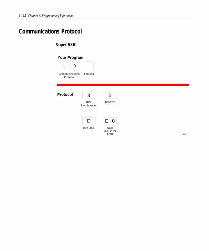
6-118 Chapter 6: Programming Information
Communications Protocol
Super ASIC
23477
Protocol
Your Program
IBMSlot Scanner
3RS-232
5
IBM USB
DNCR
(RS-232)USB
E 0
CommunicationsProtocol
1 0
Protocol

Chapter 6: Programming Information 6-119
Good Read Tone
Tone On/OffA
Off
0
On
ToneFrequency(Hertz)
ToneVolume
Tone Length(Milliseconds)
Not-On-FileTone Volume
When entering Tone Frequency, the adjustment can be incremented upward by scanning the Hex B tag. Each time you scan the Hex B, the tone frequency increases one unit. Scan the End tag or a valid Hex tag to end this mode.
When entering Tone Length, the adjustment can be incremented upward by scanning the Hex C tag. Each time you scan the Hex C tag, the tone length increases one unit. Scan the End tag or a valid Hex tag to end this mode.
When entering Tone Volume, the adjustment can be incremented upward by scanning the Hex D tag. Each time you scan the Hex D tag, the tone length increases one unit. Scan the End tag or a valid Hex tag to end this mode.
When entering Not-On-File Tone Volume, the adjustment can be incremented upward by scanning the Hex E tag. Each time you scan the Hex E tag, the tone length increases one unit. Scan the End tag or a valid Hex tag to end this mode.
B
C
D
C
D
EE
1
B
22761
Your Program
Good Read Tone
1 1
Protocol

6-120 Chapter 6: Programming Information
Timers
All Models
NOTE: NCR suggests that you do not set the Active Timeparameter to 0. Leaving the laser light on all the time reducesits life expectancy.
Lockout Time(Milliseconds)
A
350
8450
0600
1750
2900
3
1050
41200
51350
61500
7
Restart Lockout Timer
B
Active Time(Minutes)
C
Off
0On
1
0
015
130
260
3
F 0Enable
1900ms Lockout TimerRestart Limit Disable
22762
AYour Program
Timers
1 2
LockoutTime
B
RestartLockoutTimer
C
ActiveTime
F
Timers
1 2
900ms lockout timerrestart limit
NOTE: Direct Entry Only.

Chapter 6: Programming Information 6-121
Release 1
NOTE: NCR suggests that you do not set the Active Timeparameter to 0. Leaving the laser light on all the time reducesits life expectancy.
Lockout Time(Milliseconds)
A
350
8450
0600
1750
2900
3
1050
41200
51350
61500
7
Restart Lockout Timer
B
Active Time(Minutes)
C
Off
0On
1
0
015
130
260
3
22762B
AYour Program
Timers
1 2
LockoutTime
B
RestartLockoutTimer
C
ActiveTime

6-122 Chapter 6: Programming Information
Release 2
NOTE: NCR suggests that you do not set the Active Timeparameter to 0. Leaving the laser light on all the time reducesits life expectancy.
Lockout Time(Milliseconds)
A
350
8450
0600
1750
2900
3
1050
41200
51350
61500
7
Restart Lockout Timer
B
Active Time(Minutes)
C
Off
0On
1
0
015
130
260
3
F 0Enable
1900ms Lockout TimerRestart Limit Disable
22762
AYour Program
Timers
1 2
LockoutTime
B
RestartLockoutTimer
C
ActiveTime
F
Timers
1 2
900ms lockout timerrestart limit
NOTE: Direct Entry Only.

Chapter 6: Programming Information 6-123
Bar Codes–1
Single/Dual ASIC
UPC/EAN
Your Program
0Disable
22763
A
UPC/EAN
A
1Enable
C Extend UPC-ATo EAN-13 0
Disable1
Enable
D Extend UPC-ETo UPC-A 0
Disable1
Enable
E PeriodicalCodes 0
Disable1
Enable
F PeriodicalCodeExtension
02-DigitOnly
15-DigitOnly
22-Digit &5-Digit
Send Data 0Data ASDecoded
1All Data IfPeriodical
Code Present
Bar Codes - 1
1 3
Version D
B
ExtendUPC-A
C
ExtendUPC-E
D
PeriodicalCodes
E
PeriodicalCode
Extension
F
SendData
B Version D 0Disable

6-124 Chapter 6: Programming Information
Super ASIC
UPC/EAN
Your Program
0Disable
22763
A
UPC/EAN
A
1Enable
C Extend UPC-ATo EAN-13
0Disable
1Enable
D Extend UPC-ETo UPC-A
0Disable
1Enable
E PeriodicalCodes 0
Disable
1Enable
PeriodicalCodeExtension
02-DigitOnly
15-DigitOnly
22-Digit &5-Digit
Send Data 0Data ASDecoded
1All Data IfPeriodical
Code Present
Bar Codes - 1
1 3
Unused
B
ExtendUPC-A
C
ExtendUPC-E
D
PeriodicalCodes
E
PeriodicalCode
Extension
SendData
B Unused 0Disable
Set 2 or 3Tag Label
F
F Set 2 or 3Tag Label
Enable
ADisable
2 Tag or 3Tag Label

Chapter 6: Programming Information 6-125
Bar Codes–2
Code 39A 0Disable
1Enable
MinimumCharactersAllowed
B 82 - F Default
Full ASCIIC 0Disable
1Enable
Check DigitPresent
D 0Disable
1Enable
TransmitCheck Digit
E 0Disable
1Enable
Allow 1- or2-CharacterTags
F 0Disable
1Enable
Your Program
24174
Code 39
A
Bar Codes - 2
1 4
MinimumCharacters
Allowed
B
FullASCII
C
Check DigitPresent
D
TransmitCheck Digit
E
Allow 1-or
2-CharacterTags
F
For SuperASIC scanners,continue to option F even if Check Digit Present Disableis chosen.
Note:
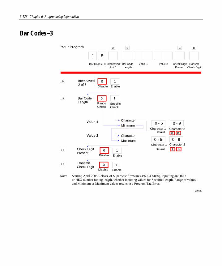
6-126 Chapter 6: Programming Information
Bar Codes–3
22765
A
B
Interleaved2 of 5
Bar Code Length
C Check DigitPresent
D
10Disable Enable
0 - 5
10Range Check
SpecificCheck
CharacterMinimum
CharacterMaximum
10Disable Enable
10Disable Enable
0 - 5 0 - 9
0 - 9
TransmitCheck Digit
Character 1 Character 2
Character 1 Character 2 Default
Default
1 6
0 8
Value 1
Value 2
Your Program A
Interleaved2 of 5
Bar Codes - 3
1 5
Check DigitPresent
C
TransmitCheck Digit
D
Value 1 Value 2Bar CodeLength
B
Starting April 2005 Release of SuperAsic firmware (497-0439869), inputting an ODD or HEX number for tag length, whether inputting values for Specific Length, Range of values, and Minimum or Maximum values results in a Program Tag Error.
Note:

Chapter 6: Programming Information 6-127
Bar Codes–4
22766
Code 128A 0Disable
1Enable
Minimum DataCharactersAllowed
B 1 2 3 4 5
EAN/UCC 128C 0Disable
1Enable
Your Program
Bar Codes - 4
1 7
A
Code 128
B
MinimumData
CharactersAllowed
C
UCC 128
Partial Decoding
F 0Disable
1Enable
F
PartialDecoding

6-128 Chapter 6: Programming Information
Bar Codes–5
24952
GS1 DataBar Enable
Scans RequiredOn GS1 DataBar 14
B
A
Disable
0Enable
GS1 DataBar 14Only
1
1 Scan
12 Scans
23 Scans
34 Scans
4
1 8
Your Program
Bar Codes - 5 GS1 DataBarEnable
A
Enable GS1 DataBar E
Only
2Enable
GS1 DataBar 14& GS1 DataBar E
3
Scans RequiredOn GS1 DataBar E
C
1 Scan
12 Scans
23 Scans
34 Scans
4
UCC-128 EmulationMode
D
Normal Mode
0UCC-128
Emulation Mode
1
B
Scans RequiredOn GS1 DataBar 14
C
Scans RequiredOn GS1 DataBar E
D
UCC-128Emulation Mode

Chapter 6: Programming Information 6-129
Bar Codes–6
23484
Your Program
Disable
2Enable
ISBN 3
1 9
Bar Codes - 6 ISBN
1. If the tag is an ISBN tag and it is enabled, the output will be the 10-digit ISBN. The 10th digit will be replaced by the ISBN checkdigit (modulo 11 with weights 10 to 2).2. If the tag is an ISSN tag and it is enabled, the output will be the 8-digit ISSN. The 8th digit will be replaced by the ISSN checkdigit (modulo 11 with weights 8 to 2).3. The LabelID used is still the LabelID for EAN-13.
For SuperASIC firmware versions (below) and upcoming releases:Programmed Firmware Chip (497-0443786) Flash MEDIA (497-0443785)
Note:Enable
8Disable
ISSN 9
ISSN
Note:

6-130 Chapter 6: Programming Information
Label Identifiers
Identifier TypeDefault Prefix
24953
A
Common Byte 1B
Common Byte 2C
Bar Code TypeD
Common Byte
Unique Identifier
0 - 7 5 Default
Hex Character(ASCII Code Chart)
0 - FHex Character
(ASCII Code Chart)
0 - 7 Default
Hex Character(ASCII Code Chart)
0 - FHex Character
(ASCII Code Chart)
None Unique Prefix
0 2 3
UPC-A
0UPC-E
2EAN-8
3EAN-13
4
Code 39
5Code 128
6Interleaved
2 of 5
7
None
0Common Byte 1
1Common Byte 2
2Both
Common Bytes
3
10 - 7Hex Character
(ASCII Code Chart)
0 - FHex Character
(ASCII Code Chart)
Common Byte andUnique Identifier Defaults varyaccording to Bar Code Type
D
4 2
GS1DataBar 14
8 9GS1 DataBar
Expanded
AIM IDOn GS1DataBar
4
UPC-D
1
1 6Identifier
TypeCommon
Byte 1Common
Byte 2
CommonByte
Unique IdentifierBar CodeType
Your Program A B C D
Label Identifiers

Chapter 6: Programming Information 6-131
Sensormatic Beep
23479
ToneFrequency (Hertz)
B B
Your Program
ProtocolCommunicationsProtocol
5 8
Note:
When entering Tone Frequency, the adjustment can beincremented upward by scanning the Hex B tag. Eachtime you scan the Hex B, the tone frequency increasesone unit. Scan the End tag or a valid Hex tag to end thismode. The five frequencies to choose from are 901, 1096,658, 738, 815 Hz. (Default: 901 Hz)
Audible Detection TagScan the Audible Detection tag first before entering theprogram sequence 58-B (Tone Frequency). The audibledetection (clicking) function allows you to get directfeedback from the scanner whenever a live EAS tag isscanned.
The Audible Detection function toggles betweenone and two beeps with each scan.1 beep - disabled 2 beeps - enabled (default)3 beeps - enabled plus deactivation tone

6-132 Chapter 6: Programming Information
RS-232 Parameters–1
22772
Baud RateA 0300
1600
21200
32400
44800
59600
619200
ParityB
Stop BitsAndCharacterLength
C
HandshakeD
0Odd
1Even
4None
01 Stop Bit
7-Bit Character
11 Stop Bit
8-Bit Character
22 Stop Bits
7-Bit Character
32 Stop Bits
8-Bit Character
0RTS Low
Ignore CTS
1RTS High
Ignore CTS
2Raise RTSWait For
CTS
3Raise RTSIgnore CTS
4RTS LowWait For
CTS
5RTS HighWait For
CTS
Your Program
BaudRate
A
RS-232Parameters - 1
2 0
Parity
B
Stop BitsAnd
CharacterLength
C
Handshake
D

Chapter 6: Programming Information 6-133
RS-232 Parameters–2
Single/Dual ASIC
2 1 RS-232 PARAMETERS - 2
A
B
C
BCC Options 0Disable
1Enable
Default: 7870-1000, 3000 - Disable7870-2000, 4000, 4500 - Enable
Interface Control 0None
1ACK/NAK
2XOn/XOff
3ACK/NAK & XOn/XOff
Check Digit 0Disable UPC-ADisable EAN-8Disable EAN-13Disable UPC-E
1Enable UPC-AEnable EAN-8Enable EAN-13Disable UPC-E
2Disable UPC-ADisable EAN-8Disable EAN-13Enable UPC-E
3Enable UPC-AEnable EAN-8Enable EAN-13Enable UPC-E
22872
Note: Check Digit parameter also applies to UPC-E when using for OCIA communications.
RS-232Parameters - 2
Your Program
2 1BCC
Options
A
ControlInterface
B C
CheckDigit

6-134 Chapter 6: Programming Information
Super ASIC
22773
BCC OptionsA
Interface ControlB
Check DigitC
0Disable
1Enable
0None
1ACK/NAK
2XOn/XOff
3ACK/NAK
&XOn/XOff
0Disable UPC-ADisable EAN-8Disable EAN-13Disable UPC-E
1Enable UPC-AEnable EAN-8Enable EAN-13Disable UPC-E
2Disable UPC-ADisable EAN-8Disable EAN-13Enable UPC-E
3Enable UPC-AEnable EAN-8Enable EAN-13Enable UPC-E
Your Program
BCC Options
A
RS-232Parameters - 2
2 1
Interface Control
B
Check Digit
C

Chapter 6: Programming Information 6-135
RS-232 Prefix Byte
22774
Prefix ByteA
ASCII CodeB
0Disable
1Enable
0 - 7Hex Character
(ASCII Code Chart)
0 - FHex Character
(ASCII Code Chart)
0 Default2
Your Program
Prefix Byte
A
RS-232Prefix Byte
2 2
ASCII Code
B

6-136 Chapter 6: Programming Information
RS-232 Terminator Byte
23478
Terminator Byte 1A
ASCII CodeB
0Disable
1Enable
0 - 7Hex Character
(ASCII Code Chart)
0 - FHex Character
(ASCII Code Chart)
0 Default3
Your Program
Prefix Byte 1
A
RS-232Terminator Byte
2 3
ASCII Code
B
NOTE: Terminator Byte 1 is required on ascale unit. If you select Disable, it is ignored and an ETX (03) is sent.
Terminator Byte 2C
ASCII Code
0Disable
1Enable
0 - 7Hex Character
(ASCII Code Chart)
0 - FHex Character
(ASCII Code Chart)
Prefix Byte 2
C
ASCII Code
NOTE: Terminator Byte 2 is a direct entry only.
When re-enabling terminator byte 1, the regular terminator byte takes the value which was programmed before it was disabled. Terminator byte 2continues to be disabled and will have to be enabled with its own sequence.
Note:

Chapter 6: Programming Information 6-137
RS-232 Communications Options
22779
No Delay
0 101010101210 Milliseconds 50 Milliseconds
RS-232 Delay
Your Program
CommunicationOptions
2 4
RS-232Delay
Scanner orScanner /
Scale Format
Good WeighTone
Scanner Only
4
Scanner / Scale
Scanner or Scanner / Scale Format
Disable
8 19
Enable
GoodWeigh Tone
5
1

6-138 Chapter 6: Programming Information
Scale Parameters

Chapter 6: Programming Information 6-139
Miscellaneous Parameters
Single/Dual ASIC
5-Second Weight Display Timer
22813B
IBM Tone Control(Good Read Tone Control)
OCIA Price Display
1Disable
2Enable
5Disable
6
3Disable
4Enable
Enable
IBM Retransmit Control 73 Times
OCIA Blank Display In Price Mode 9Disable
Enable/Disable Voice Messages D Toggle between Enable andDisable Speech (Default: Enable)
IBM Tag Data Format EHex
8Forever
AEnable
FASCII
3 2
Your Program
MiscellaneousParameters
5-Second Weight Display Timer
IBM Tone Control
OCIA Price Display
IBM Retransmit Control
OCIA Blank Display In Price Mode
Enable / Disable Voice Messages (Toggle)
IBM Tag Data Format

6-140 Chapter 6: Programming Information
Super ASIC
Host Tone Control
Your Program
MiscellaneousParameters
Disable
3Enable
4
3 2
Host ToneControl
Speech Toggle Between Enableand Disable SpeechD
IBM RetransmitControl
IBM Retransmit Control3 Times
7Forever
8
22813
IBM-485 / IBM-USB TagData Format Hex
EASCII
F
Speech IBM-485 / IBM-USB Tag Data Format

Chapter 6: Programming Information 6-141
Code 128 Tone Length
24383
Selection Programming Tag Sequence
Programming Mode, Hex 7, Hex 0, Hex 0, Hex 2, Save and Reset30 ms
45 ms Programming Mode, Hex 7, Hex 0, Hex 0, Hex 3, Save and Reset60 ms Programming Mode, Hex 7, Hex 0, Hex 0, Hex 4, Save and Reset
75 ms Programming Mode, Hex 7, Hex 0, Hex 0, Hex 5, Save and Reset
150 ms Programming Mode, Hex 7, Hex 0, Hex 0, Hex A, Save and Reset
180 ms Programming Mode, Hex 7, Hex 0, Hex 0, Hex C, Save and Reset195 ms Programming Mode, Hex 7, Hex 0, Hex 0, Hex D, Save and Reset
165 ms Programming Mode, Hex 7, Hex 0, Hex 0, Hex B, Save and Reset
0 ms Programming Mode, Hex 7, Hex 0, Hex 0, Hex 0, Save and Reset15 ms Programming Mode, Hex 7, Hex 0, Hex 0, Hex 1, Save and Reset
90 ms Programming Mode, Hex 7, Hex 0, Hex 0, Hex 6, Save and Reset105 ms Programming Mode, Hex 7, Hex 0, Hex 0, Hex 7, Save and Reset120 ms Programming Mode, Hex 7, Hex 0, Hex 0, Hex 8, Save and Reset135 ms Programming Mode, Hex 7, Hex 0, Hex 0, Hex 9, Save and Reset
210 ms Programming Mode, Hex 7, Hex 0, Hex 0, Hex E, Save and Reset225 ms Programming Mode, Hex 7, Hex 0, Hex 0, Hex F, Save and Reset
Code 128 Tone Frequency
24468
Selection Programming Tag Sequence
Programming Mode, Hex 7, Hex 0, Hex 1, Hex 2, Save and Reset775 Hz
860 Hz Programming Mode, Hex 7, Hex 0, Hex 1, Hex 3, Save and Reset947 Hz Programming Mode, Hex 7, Hex 0, Hex 1, Hex 4, Save and Reset
1250 Hz Programming Mode, Hex 7, Hex 0, Hex 1, Hex 5, Save and Reset
617 Hz Programming Mode, Hex 7, Hex 0, Hex 1, Hex 0, Save and Reset
705 Hz Programming Mode, Hex 7, Hex 0, Hex 1, Hex 1, Save and Reset
524 Hz Programming Mode, Hex 7, Hex 0, Hex 1, Hex 6, Save and Reset572 Hz Programming Mode, Hex 7, Hex 0, Hex 1, Hex 7, Save and Reset

6-142 Chapter 6: Programming Information
Code 128 Tone
24384
Selection Programming Tag Sequence
Disable Programming Mode, Hex 7, Hex 0, Hex 2, Hex 0, Save and Reset
Enable Programming Mode, Hex 7, Hex 0, Hex 2, Hex 1, Save and Reset
Code 128 Minimum and Maximum Tag Length
24954
Selection Programming Tag Sequence
v = 1-3 (default is 3)w = 1-9 (default is 9)x = 1-3 (default is 3)y = 1-9 (default is 9)
Scan Default Tag
Length Programming Mode, Hex 7, Hex 2, a, v, w, x, y, Save and Reset
where a = Ø (Range of lengths) or 1 (Specific Length)
Default

Chapter 6: Programming Information 6-143
Code 39 Tone Length
24385
Selection Programming Tag Sequence
Programming Mode, Hex 7, Hex 0, Hex 3, Hex 2, Save and Reset30 ms
45 ms Programming Mode, Hex 7, Hex 0, Hex 3, Hex 3, Save and Reset60 ms Programming Mode, Hex 7, Hex 0, Hex 3, Hex 4, Save and Reset
75 ms Programming Mode, Hex 7, Hex 0, Hex 3, Hex 5, Save and Reset
150 ms Programming Mode, Hex 7, Hex 0, Hex 3, Hex A, Save and Reset
180 ms Programming Mode, Hex 7, Hex 0, Hex 3, Hex C, Save and Reset195 ms Programming Mode, Hex 7, Hex 0, Hex 3, Hex D, Save and Reset
165 ms Programming Mode, Hex 7, Hex 0, Hex 3, Hex B, Save and Reset
0 ms Programming Mode, Hex 7, Hex 0, Hex 3, Hex 0, Save and Reset15 ms Programming Mode, Hex 7, Hex 0, Hex 3, Hex 1, Save and Reset
90 ms Programming Mode, Hex 7, Hex 0, Hex 3, Hex 6, Save and Reset105 ms Programming Mode, Hex 7, Hex 0, Hex 3, Hex 7, Save and Reset120 ms Programming Mode, Hex 7, Hex 0, Hex 3, Hex 8, Save and Reset135 ms Programming Mode, Hex 7, Hex 0, Hex 3, Hex 9, Save and Reset
210 ms Programming Mode, Hex 7, Hex 0, Hex 3, Hex E, Save and Reset225 ms Programming Mode, Hex 7, Hex 0, Hex 3, Hex F, Save and Reset
Code 128 Stitch
24386
Selection Programming Tag Sequence
Disable Programming Mode, Hex 7, Hex 0, Hex 9, Hex C, Save and Reset
Enable Programming Mode, Hex 7, Hex 0, Hex 9, Hex D, Save and Reset

6-144 Chapter 6: Programming Information
Code 39 Tone Frequency
24387
Selection Programming Tag Sequence
Programming Mode, Hex 7, Hex 0, Hex 4, Hex 2, Save and Reset775 Hz
860 Hz Programming Mode, Hex 7, Hex 0, Hex 4, Hex 3, Save and Reset947 Hz Programming Mode, Hex 7, Hex 0, Hex 4, Hex 4, Save and Reset
1250 Hz Programming Mode, Hex 7, Hex 0, Hex 4, Hex 5, Save and Reset
617 Hz Programming Mode, Hex 7, Hex 0, Hex 4, Hex 0, Save and Reset
705 Hz Programming Mode, Hex 7, Hex 0, Hex 4, Hex 1, Save and Reset
524 Hz Programming Mode, Hex 7, Hex 0, Hex 4, Hex 6, Save and Reset572 Hz Programming Mode, Hex 7, Hex 0, Hex 4, Hex 7, Save and Reset
Code 39 Tone
24388
Selection Programming Tag Sequence
Disable Programming Mode, Hex 7, Hex 0, Hex 5, Hex 0, Save and Reset
Enable Programming Mode, Hex 7, Hex 0, Hex 5, Hex 1, Save and Reset
Code 39 Quiet Zone
24389
Selection Programming Tag Sequence
Disable Programming Mode, Hex 7, Hex 0, Hex 5, Hex 2, Save and Reset
Enable Programming Mode, Hex 7, Hex 0, Hex 5, Hex 3, Save and Reset

Chapter 6: Programming Information 6-145
Code 39 InterCharacter Gap Check
24390
Selection Programming Tag Sequence
Enable Programming Mode, Hex 7, Hex 0, Hex 5, Hex 5, Save and Reset
Disable Programming Mode, Hex 7, Hex 0, Hex 5, Hex 4, Save and Reset
Code 39 Halves
24451
Selection Programming Tag Sequence
Disable Programming Mode, Hex 7, Hex 0, Hex 9, Hex 0, Save and ResetEnable Programming Mode, Hex 7, Hex 0, Hex 9, Hex 1, Save and Reset
Code 39 Stitch
24452
Selection Programming Tag Sequence
Disable Programming Mode, Hex 7, Hex 0, Hex 9, Hex 2, Save and ResetEnable Programming Mode, Hex 7, Hex 0, Hex 9, Hex 3, Save and Reset

6-146 Chapter 6: Programming Information
Code 39 CD Length1
24454
Selection Programming Tag Sequence
Length Programming Mode, Hex 7, Hex 0, Hex B, Hex x, Hex y, Save and ResetCD Length x y = 01 - 36 where if x = 0 , y = 1 - 9
x = 1 , y = 0 - 9 x = 2 , y = 0 - 9 x = 3 , y = 0 - 6
Programming Mode, Hex 7, Hex 0, Hex B, Hex 0, Hex 0, Save and ResetDisable
Setting
Default
Code 39 CD Length2
24455
Selection Programming Tag Sequence
Length Programming Mode, Hex 7, Hex 0, Hex C, Hex x, Hex y, Save and ResetCD Length x y = 01 - 36 where if x = 0 , y = 1 - 9
x = 1 , y = 0 - 9 x = 2 , y = 0 - 9 x = 3 , y = 0 - 6
Programming Mode, Hex 7, Hex 0, Hex C, Hex 0, Hex 0, Save and ResetDisable
Setting
Default

Chapter 6: Programming Information 6-147
Interleaved 2 of 5 Tone Length
24456
Selection Programming Tag Sequence
Programming Mode, Hex 7, Hex 0, Hex 6, Hex 2, Save and Reset30 ms
45 ms Programming Mode, Hex 7, Hex 0, Hex 6, Hex 3, Save and Reset60 ms Programming Mode, Hex 7, Hex 0, Hex 6, Hex 4, Save and Reset
75 ms Programming Mode, Hex 7, Hex 0, Hex 6, Hex 5, Save and Reset
150 ms Programming Mode, Hex 7, Hex 0, Hex 6, Hex A, Save and Reset
180 ms Programming Mode, Hex 7, Hex 0, Hex 6, Hex C, Save and Reset195 ms Programming Mode, Hex 7, Hex 0, Hex 6, Hex D, Save and Reset
165 ms Programming Mode, Hex 7, Hex 0, Hex 6, Hex B, Save and Reset
0 ms Programming Mode, Hex 7, Hex 0, Hex 6, Hex 0, Save and Reset15 ms Programming Mode, Hex 7, Hex 0, Hex 6, Hex 1, Save and Reset
90 ms Programming Mode, Hex 7, Hex 0, Hex 6, Hex 6, Save and Reset105 ms Programming Mode, Hex 7, Hex 0, Hex 6, Hex 7, Save and Reset120 ms Programming Mode, Hex 7, Hex 0, Hex 6, Hex 8, Save and Reset135 ms Programming Mode, Hex 7, Hex 0, Hex 6, Hex 9, Save and Reset
210 ms Programming Mode, Hex 7, Hex 0, Hex 6, Hex E, Save and Reset225 ms Programming Mode, Hex 7, Hex 0, Hex 6, Hex F, Save and Reset
Interleaved 2 of 5 Tone Frequency
24457
Selection Programming Tag Sequence
Programming Mode, Hex 7, Hex 0, Hex 7, Hex 2, Save and Reset775 Hz
860 Hz Programming Mode, Hex 7, Hex 0, Hex 7, Hex 3, Save and Reset947 Hz Programming Mode, Hex 7, Hex 0, Hex 7, Hex 4, Save and Reset
1250 Hz Programming Mode, Hex 7, Hex 0, Hex 7, Hex 5, Save and Reset
617 Hz Programming Mode, Hex 7, Hex 0, Hex 7, Hex 0, Save and Reset
705 Hz Programming Mode, Hex 7, Hex 0, Hex 7, Hex 1, Save and Reset
524 Hz Programming Mode, Hex 7, Hex 0, Hex 7, Hex 6, Save and Reset572 Hz Programming Mode, Hex 7, Hex 0, Hex 7, Hex 7, Save and Reset

6-148 Chapter 6: Programming Information
Interleaved 2 of 5 Tone
24458
Selection Programming Tag Sequence
Disable Programming Mode, Hex 7, Hex 0, Hex 8, Hex 0, Save and ResetEnable Programming Mode, Hex 7, Hex 0, Hex 8, Hex 1, Save and Reset
Interleaved 2 of 5 CD Length1
24460
Selection Programming Tag Sequence
Length Programming Mode, Hex 7, Hex 0, Hex D, Hex x, Hex y, Save and ResetCD Length x y = 04 - 58 where if x = 0 , y = 4 - 9
x = 1 , y = 0 - 9 x = 2 , y = 0 - 9 x = 3 , y = 0 - 9
Programming Mode, Hex 7, Hex 0, Hex D, Hex 0, Hex 0, Save and ResetDisable
Setting
Default
x = 4 , y = 0 - 9 x = 5 , y = 0 - 8
Interleaved 2 of 5 CD Length2
24461
Selection Programming Tag Sequence
Length Programming Mode, Hex 7, Hex 0, Hex E, Hex x, Hex y, Save and ResetCD Length x y = 04 - 58 where if x = 0 , y = 4 - 9
x = 1 , y = 0 - 9 x = 2 , y = 0 - 9 x = 3 , y = 0 - 9
Programming Mode, Hex 7, Hex 0, Hex E, Hex 0, Hex 0, Save and ResetDisable
Setting
Default
x = 4 , y = 0 - 9 x = 5 , y = 0 - 8
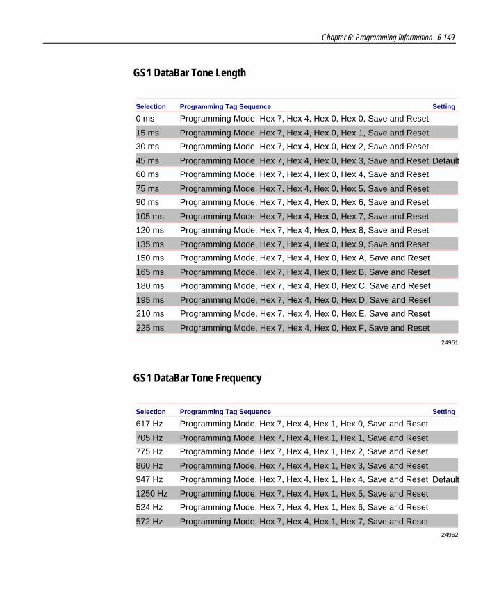
Chapter 6: Programming Information 6-149
GS1 DataBar Tone Length
24961
Selection Programming Tag Sequence
Programming Mode, Hex 7, Hex 4, Hex 0, Hex 1, Save and Reset
0 ms Programming Mode, Hex 7, Hex 4, Hex 0, Hex 0, Save and Reset
15 ms
Programming Mode, Hex 7, Hex 4, Hex 0, Hex 3, Save and Reset
30 ms Programming Mode, Hex 7, Hex 4, Hex 0, Hex 2, Save and Reset
45 ms
Programming Mode, Hex 7, Hex 4, Hex 0, Hex 5, Save and Reset
60 ms Programming Mode, Hex 7, Hex 4, Hex 0, Hex 4, Save and Reset
75 ms
Programming Mode, Hex 7, Hex 4, Hex 0, Hex 7, Save and Reset
90 ms Programming Mode, Hex 7, Hex 4, Hex 0, Hex 6, Save and Reset
105 ms
Programming Mode, Hex 7, Hex 4, Hex 0, Hex 9, Save and Reset
120 ms Programming Mode, Hex 7, Hex 4, Hex 0, Hex 8, Save and Reset
135 ms
Programming Mode, Hex 7, Hex 4, Hex 0, Hex B, Save and Reset
150 ms Programming Mode, Hex 7, Hex 4, Hex 0, Hex A, Save and Reset
165 ms
Programming Mode, Hex 7, Hex 4, Hex 0, Hex D, Save and Reset 180 ms Programming Mode, Hex 7, Hex 4, Hex 0, Hex C, Save and Reset
195 ms
Programming Mode, Hex 7, Hex 4, Hex 0, Hex F, Save and Reset
210 ms Programming Mode, Hex 7, Hex 4, Hex 0, Hex E, Save and Reset
225 ms
Setting
Default
GS1 DataBar Tone Frequency
24962
Selection Programming Tag Sequence
Programming Mode, Hex 7, Hex 4, Hex 1, Hex 1, Save and Reset
617 Hz Programming Mode, Hex 7, Hex 4, Hex 1, Hex 0, Save and Reset
705 Hz
Programming Mode, Hex 7, Hex 4, Hex 1, Hex 3, Save and Reset
775 Hz Programming Mode, Hex 7, Hex 4, Hex 1, Hex 2, Save and Reset
860 Hz
Programming Mode, Hex 7, Hex 4, Hex 1, Hex 5, Save and Reset
947 Hz Programming Mode, Hex 7, Hex 4, Hex 1, Hex 4, Save and Reset
1250 Hz
Programming Mode, Hex 7, Hex 4, Hex 1, Hex 7, Save and Reset
524 Hz Programming Mode, Hex 7, Hex 4, Hex 1, Hex 6, Save and Reset
572 Hz
Setting
Default

6-150 Chapter 6: Programming Information
GS1 DataBar Tone
24963
Selection Programming Tag Sequence
Programming Mode, Hex 7, Hex 4, Hex 2, Hex 1, Save and Reset
Disable Programming Mode, Hex 7, Hex 4, Hex 2, Hex 0, Save and Reset
Enable
Setting
Default
GS1 DataBar–E AI 93 to Code 39 Tag Data Conversion
24955
Selection Programming Tag Sequence
Programming Mode, Hex 7, Hex 0, Hex A, Hex 3, Save and Reset
Disable Programming Mode, Hex 7, Hex 0, Hex A, Hex 2, Save and Reset
Enable
Setting
Default
GS1 DataBar–E AI 94 to UCC–128 Tag Data Conversion
24956
Selection Programming Tag Sequence
Programming Mode, Hex 7, Hex 0, Hex A, Hex 5, Save and Reset
Disable Programming Mode, Hex 7, Hex 0, Hex A, Hex 4, Save and Reset
Enable
Setting
Default
GS1 DataBar–E AI 94 to Code–128 Tag Data Conversion
24957
Selection Programming Tag Sequence
Programming Mode, Hex 7, Hex 0, Hex A, Hex 7, Save and Reset
Disable Programming Mode, Hex 7, Hex 0, Hex A, Hex 6, Save and Reset
Enable
Setting
Default
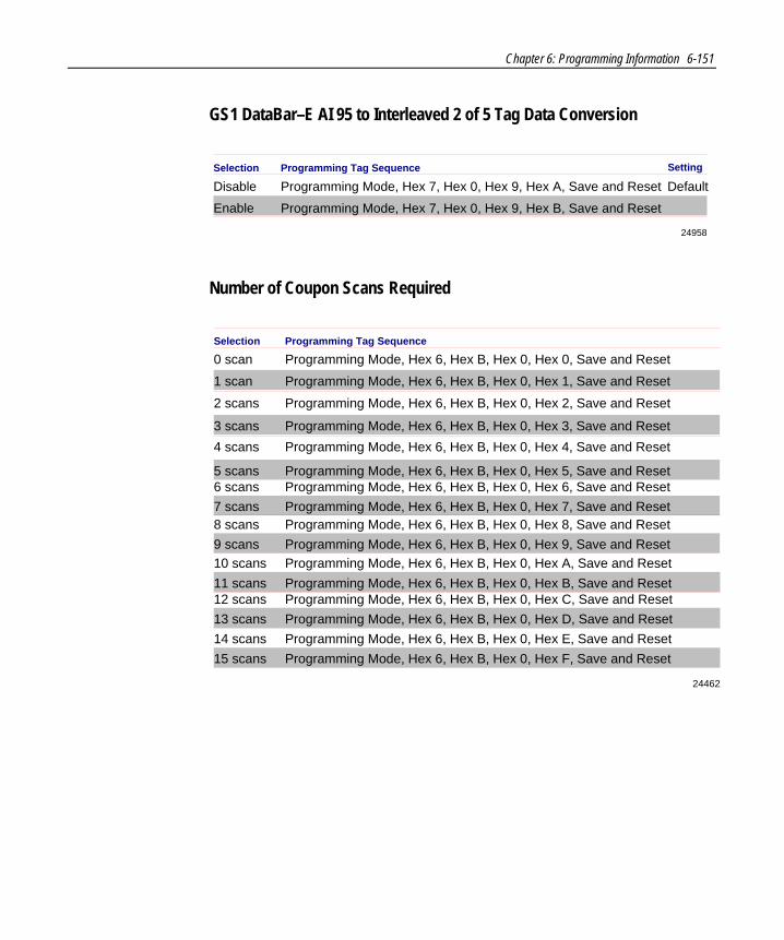
Chapter 6: Programming Information 6-151
GS1 DataBar–E AI 95 to Interleaved 2 of 5 Tag Data Conversion
24958
Selection Programming Tag Sequence
Programming Mode, Hex 7, Hex 0, Hex 9, Hex B, Save and Reset
Disable Programming Mode, Hex 7, Hex 0, Hex 9, Hex A, Save and Reset
Enable
Setting
Default
Number of Coupon Scans Required
24462
Selection Programming Tag Sequence
Programming Mode, Hex 6, Hex B, Hex 0, Hex 2, Save and Reset2 scans
3 scans Programming Mode, Hex 6, Hex B, Hex 0, Hex 3, Save and Reset4 scans Programming Mode, Hex 6, Hex B, Hex 0, Hex 4, Save and Reset
5 scans Programming Mode, Hex 6, Hex B, Hex 0, Hex 5, Save and Reset
10 scans Programming Mode, Hex 6, Hex B, Hex 0, Hex A, Save and Reset
12 scans Programming Mode, Hex 6, Hex B, Hex 0, Hex C, Save and Reset13 scans Programming Mode, Hex 6, Hex B, Hex 0, Hex D, Save and Reset
11 scans Programming Mode, Hex 6, Hex B, Hex 0, Hex B, Save and Reset
0 scan Programming Mode, Hex 6, Hex B, Hex 0, Hex 0, Save and Reset1 scan Programming Mode, Hex 6, Hex B, Hex 0, Hex 1, Save and Reset
6 scans Programming Mode, Hex 6, Hex B, Hex 0, Hex 6, Save and Reset7 scans Programming Mode, Hex 6, Hex B, Hex 0, Hex 7, Save and Reset8 scans Programming Mode, Hex 6, Hex B, Hex 0, Hex 8, Save and Reset9 scans Programming Mode, Hex 6, Hex B, Hex 0, Hex 9, Save and Reset
14 scans Programming Mode, Hex 6, Hex B, Hex 0, Hex E, Save and Reset15 scans Programming Mode, Hex 6, Hex B, Hex 0, Hex F, Save and Reset

6-152 Chapter 6: Programming Information
Number of UPC/EAN Scans Required
24463
Selection Programming Tag Sequence
Programming Mode, Hex 6, Hex B, Hex 3, Hex 3, Save and Reset3 scans
4 scans Programming Mode, Hex 6, Hex B, Hex 3, Hex 4, Save and Reset
1 scan Programming Mode, Hex 6, Hex B, Hex 3, Hex 1, Save and Reset
2 scans Programming Mode, Hex 6, Hex B, Hex 3, Hex 2, Save and Reset
Number of Code 39 Scans Required
24464
Selection Programming Tag Sequence
Programming Mode, Hex 6, Hex B, Hex 4, Hex 3, Save and Reset3 scans
4 scans Programming Mode, Hex 6, Hex B, Hex 4, Hex 4, Save and Reset
1 scan Programming Mode, Hex 6, Hex B, Hex 4, Hex 1, Save and Reset
2 scans Programming Mode, Hex 6, Hex B, Hex 4, Hex 2, Save and Reset
Number of Interleaved 2 of 5 Scans Required
24465
Selection Programming Tag Sequence
Programming Mode, Hex 6, Hex B, Hex 5, Hex 3, Save and Reset3 scans
4 scans Programming Mode, Hex 6, Hex B, Hex 5, Hex 4, Save and Reset
1 scan Programming Mode, Hex 6, Hex B, Hex 5, Hex 1, Save and Reset
2 scans Programming Mode, Hex 6, Hex B, Hex 5, Hex 2, Save and Reset
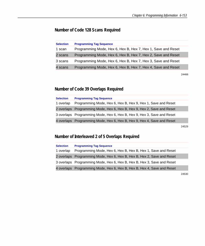
Chapter 6: Programming Information 6-153
Number of Code 128 Scans Required
24466
Selection Programming Tag Sequence
Programming Mode, Hex 6, Hex B, Hex 7, Hex 3, Save and Reset3 scans
4 scans Programming Mode, Hex 6, Hex B, Hex 7, Hex 4, Save and Reset
1 scan Programming Mode, Hex 6, Hex B, Hex 7, Hex 1, Save and Reset
2 scans Programming Mode, Hex 6, Hex B, Hex 7, Hex 2, Save and Reset
Number of Code 39 Overlaps Required
24529
Selection Programming Tag Sequence
Programming Mode, Hex 6, Hex B, Hex 9, Hex 3, Save and Reset3 overlaps
4 overlaps Programming Mode, Hex 6, Hex B, Hex 9, Hex 4, Save and Reset
1 overlap Programming Mode, Hex 6, Hex B, Hex 9, Hex 1, Save and Reset
2 overlaps Programming Mode, Hex 6, Hex B, Hex 9, Hex 2, Save and Reset
Number of Interleaved 2 of 5 Overlaps Required
24530
Selection Programming Tag Sequence
Programming Mode, Hex 6, Hex B, Hex B, Hex 3, Save and Reset3 overlaps
4 overlaps Programming Mode, Hex 6, Hex B, Hex B, Hex 4, Save and Reset
1 overlap Programming Mode, Hex 6, Hex B, Hex B, Hex 1, Save and Reset
2 overlaps Programming Mode, Hex 6, Hex B, Hex B, Hex 2, Save and Reset

6-154 Chapter 6: Programming Information
Number of Minimum Code 39 Characters in Code 39 Partial
Selection Programming Tag Sequence
Programming Mode, Hex 6, Hex B, Hex C, Hex 4, Save and Reset4 characters
5 characters Programming Mode, Hex 6, Hex B, Hex C, Hex 5, Save and Reset
2 characters Programming Mode, Hex 6, Hex B, Hex C, Hex 2, Save and Reset
3 characters Programming Mode, Hex 6, Hex B, Hex C, Hex 3, Save and Reset
Programming Mode, Hex 6, Hex B, Hex C, Hex 6, Save and Reset6 characters
7 characters Programming Mode, Hex 6, Hex B, Hex C, Hex 7, Save and Reset
24531
Programming Mode, Hex 6, Hex B, Hex C, Hex 8, Save and Reset8 characters
9 characters Programming Mode, Hex 6, Hex B, Hex C, Hex 9, Save and Reset
Number of Code 128 Overlaps Required
24532
Selection Programming Tag Sequence
Programming Mode, Hex 6, Hex B, Hex D, Hex 3, Save and Reset3 overlaps
4 overlaps Programming Mode, Hex 6, Hex B, Hex D, Hex 4, Save and Reset
1 overlap Programming Mode, Hex 6, Hex B, Hex D, Hex 1, Save and Reset
2 overlaps Programming Mode, Hex 6, Hex B, Hex D, Hex 2, Save and Reset
Number of Minimum Interleaved 2 of 5 Characters in Interleaved 2 of 5 Partial
Selection Programming Tag Sequence
Programming Mode, Hex 6, Hex B, Hex E, Hex 4, Save and Reset4 characters
5 characters Programming Mode, Hex 6, Hex B, Hex E, Hex 5, Save and Reset
2 characters Programming Mode, Hex 6, Hex B, Hex E, Hex 2, Save and Reset
3 characters Programming Mode, Hex 6, Hex B, Hex E, Hex 3, Save and Reset
Programming Mode, Hex 6, Hex B, Hex E, Hex 6, Save and Reset6 characters
7 characters Programming Mode, Hex 6, Hex B, Hex E, Hex 7, Save and Reset
24533
Programming Mode, Hex 6, Hex B, Hex E, Hex 8, Save and Reset8 characters
9 characters Programming Mode, Hex 6, Hex B, Hex E, Hex 9, Save and Reset

Chapter 6: Programming Information 6-155
Number of Minimum Code 128 Characters in Code 128 Partial
Programming Mode, Hex 6, Hex B, Hex F, Hex 4, Save and Reset4 characters
5 characters Programming Mode, Hex 6, Hex B, Hex F, Hex 5, Save and ResetProgramming Mode, Hex 6, Hex B, Hex F, Hex 6, Save and Reset6 characters
7 characters Programming Mode, Hex 6, Hex B, Hex F, Hex 7, Save and Reset
24534
Programming Mode, Hex 6, Hex B, Hex F, Hex 8, Save and Reset8 characters
9 characters Programming Mode, Hex 6, Hex B, Hex F, Hex 9, Save and Reset
Command–type Disable
24959
Selection Programming Tag Sequence
Programming Mode, Hex 6, Hex 7, Hex 9, Save and Reset
Disable Programming Mode, Hex 6, Hex 7, Hex 8, Save and Reset
Enable
Setting
Default
Ignore RS–232 Commands from POS
24960
Selection Programming Tag Sequence
Programming Mode, Hex 7, Hex 0, Hex A, Hex 1
Disable Programming Mode, Hex 7, Hex 0, Hex A, Hex 0
Enable
DefaultSetting
GS1 DataBar Coupon Support
24964
Selection Programming Tag Sequence
Programming Mode, Hex 7, Hex 1, Hex D, Save and Reset
Enable Programming Mode, Hex 7, Hex 1, Hex C, Save and Reset
Disable
Setting
Default

6-156 Chapter 6: Programming Information
GS1 DataBar AI 8110 coupons
GS1 DataBar 8110
24965
Selection Programming Tag Sequence
Programming Mode, Hex 7, Hex 1, Hex 2, Save and Reset
Disable Programming Mode, Hex 7, Hex 1, Hex 0, Save and Reset
Enable
Setting
Default
GS1 DataBar–E AI 8110
24966
Selection Programming Tag Sequence
Programming Mode, Hex 7, Hex 1, Hex3, Save and Reset
Disable Programming Mode, Hex 7, Hex 1, Hex 1, Save and Reset
Enable
Setting
Default
EAN–13 98 coupons
24967
Selection Programming Tag Sequence
Programming Mode, Hex 7, Hex 1, Hex 9, Save and Reset
Enable Programming Mode, Hex 7, Hex 1, Hex 8, Save and Reset
Disable
Setting
Default
EAN–13 99 coupons
24968
Selection Programming Tag Sequence
Programming Mode, Hex 7, Hex 1, Hex B, Save and Reset
Enable Programming Mode, Hex 7, Hex 1, Hex A, Save and Reset
Disable
Setting
Default
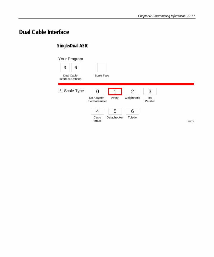
Chapter 6: Programming Information 6-157
Dual Cable Interface
Single/Dual ASIC
Scale TypeA 0No Adapter -
Exit ParameterAvery Weightronix Tec
Parallel
CasioParallel
Your Program
Dual CableInterface Options
3
Scale Type
22873
Datachecker Toledo
1 2 3
4 5 6
6

6-158 Chapter 6: Programming Information
ASCII Code Chart
707172737475767778797A7B7C7D7E7F
pqrstuvwxyz{|}
DEL
606162636465666768696A6B6C6D6E6F
abcdefghijklmno
505152535455565758595A5B5C5D5E5F
PQRSTUVWXYZ[\]^_
404142434445464748494A4B4C4D4E4F
@ABCDEFGHIJKLMNO
303132333435363738393A3B3C3D3E3F
01234
65
789:;<=>?
202122232425262728292A2B2C2D2E2F
SP!"#$%&'()*+,-./
101112131415161718191A1B1C1D1E1F
DLEDC1DC2DC3DC4NAKSYNETBCANEMSUBESCFSGSRSUS
000102030405060708090A0B0C0D0E0F
NULLSOHSTXETXEOTENQACKBELBSHTLFVTFFCRS0S1
R0040
~

Appendix A: Cable Configuration
Single-Cable Configuration
14958
DC
POW
ER
REM
OTE
DIS
PLA
Y5A
MA
X
SCA
NN
ER
Check switch settings
5V
DCPower Cable
RemoteDisplay
ACPowerCord
PowerSupply
RealScan 75Scanner/Scale
InterfaceCable
HostTerminal
PORT 1 PORT 2
DUAL PERIPHERAL PORTS
RS-232Peripheral
A

A-2 Appendix A: Cable Configuration
1. Connect the power cable from the power supply to the DC POWER connector.
2. Connect the interface cable to the SCANNER connector.
3. If used, connect the remote display cable to the REMOTE DISPLAY connector.
4. If the configuration includes an RS‐232 peripheral device, click the first button. Otherwise, click one of the two bottom buttons.
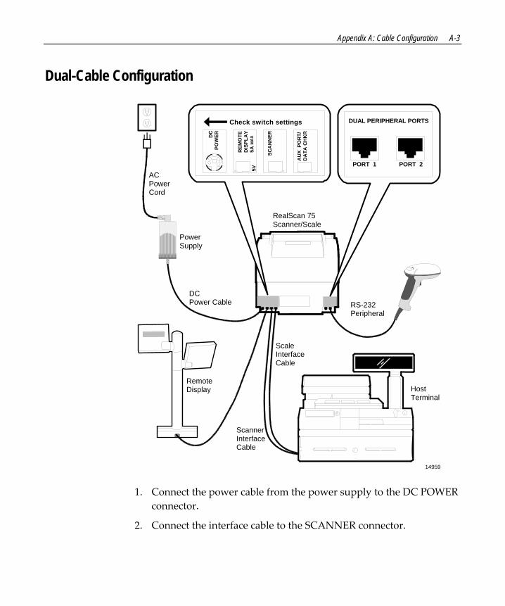
Appendix A: Cable Configuration A-3
Dual-Cable Configuration
14959
DCPower Cable
RemoteDisplay
ACPowerCord
PowerSupply
RealScan 75Scanner/Scale
ScaleInterfaceCable
HostTerminal
RS-232Peripheral
DC
POW
ER
REM
OTE
DIS
PLA
Y5A
MA
X
SCA
NN
ER
AU
X P
OR
T/D
ATA
CH
KR
Check switch settings
5V
ScannerInterfaceCable
PORT 1 PORT 2
DUAL PERIPHERAL PORTS
1. Connect the power cable from the power supply to the DC POWER connector.
2. Connect the interface cable to the SCANNER connector.

A-4 Appendix A: Cable Configuration
3. Connect the scale interface cable to the AUX PORT/DATA CHKR connector.
4. If used, connect the remote display cable to the REMOTE DISPLAY connector.
5. If the configuration includes an RS‐232 peripheral device, click the first button. Otherwise, click the bottom button.

Appendix A: Cable Configuration A-5
Bizerba Scale Configuration
19318
DC
POW
ER
REM
OTE
DIS
PLA
Y5A
MA
X
SCA
NN
ER
Check switch settings
5VDCPower Cable
ACPowerCord
PowerSupply
RealScan 75Scanner/Scale
ScaleCable
HostTerminal
BizerbaDisplay
kg T kg Preis/kg Preis
InterfaceCable
1. Connect the power cable from the power supply to the DC POWER connector.
2. Connect the interface cable to the SCANNER connector.
3. Connect the Bizerba Display to the RealScan 75.

A-6 Appendix A: Cable Configuration
4. Connect the scale cable from the host terminal to the RealScan 75.
5. If the RealScan 75 is a Super ASIC model, click the first button. Otherwise, click the bottom button.
RealScan 75-7xxx/8xxx
20553
DCPower Cable
RemoteDisplay
ACPowerCord
PowerSupply RealScan 75
InterfaceCable
HostTerminal RS-232
Peripheral
BCAN I/O POS SERVICE REMOTE ANTENNAEXPANSIONBR
MNS
PROGSTATUS
PORT 1 PORT 2
DUAL PERIPHERAL PORTS
SensormaticScanMax™ Pro ControllerSensormatic
Interlock Cable
SensormaticAntennaCable
AC PowerCord
1. Connect the power cable from the power supply to the DC POWER connector.
2. Connect the interface cable to the SCANNER connector.
3. If used, connect the remote display cable to the REMOTE DISPLAY connector.

Appendix A: Cable Configuration A-7
4. Route the Sensormatic® Deactivation cable through the front of the RealScan 75 and connect it to the Sensormatic ScanMax™ Pro Controller.
5. Connect one end of the Sensormatic® Interlock cable to one of the RS‐232 Peripheral connectors and the other end to the Sensormatic ScanMax™ Pro Controller.
6. If the configuration includes an RS‐232 peripheral device, click the first button. Otherwise, click the bottom button.


Appendix B: Connect the Peripheral Devices
RS-232 peripheral device (hand-held scanner) RS‐232 peripheral devices cannot be connected to an NCR RealScan 75‐4xxx with a Bizerba scale.
14965
PORT 1 PORT 2
DUAL PERIPHERAL PORTSDUAL PERIPHERAL PORTS
PORT 1 PORT 2
After Serial Number 32660591 Before Serial Number 32660592
If you are connecting an RS‐232 peripheral device, such as a hand‐held scanner, connect the cable to one of the two dual peripheral ports located in the back on the bottom of the tower area of the unit, as shown in the illustration. The port you use must also be set in one of the program parameters.
Note: Some peripherals are limited to which port they can use. Refer to Special Installations.
B

B-2 Appendix B: Connect the Peripheral Devices
For Units before Serial Number 32660592 If the RealScan 75 does not have a Strain Relief mounted to the bottom of the Mounting Bracket (bucket) to hold the peripheral device cable, you must attach one. Do this by removing the paper from the adhesive tape on the Strain Relief (006‐8601511), then press the Strain Relief onto the RealScan 75. Use a cable tie (006‐0002011) to fasten the cable to the Strain Relief.
If the RealScan 75 is a Super ASIC model, click the first button. Otherwise, click the bottom button.
Install the Unit into the Checkstand Cutout (Super ASIC models only)
15184
1. Verify that the top of the RealScan 75 Supports are set to the initial distance from the top of the checkstand: 0.95 cm (0.375 in) for scanner only units and 1.27 cm (0.50 in) for scanner/scale units.

Appendix B: Connect the Peripheral Devices B-3
2. By holding the handle on the back of the tower cabinet and the front of the unit, slowly lower the RealScan 75 into the checkstand cutout. For proper operation, the RealScan 75 must be level. It should have support within five centimeters (two inches) of its corners so that it does not rock.
3. Install the Top Plate on the four supports (rubber posts).
Note: It is important that the RealScan 75 does not rock on its supports. Make sure that all adjustable supports are securely fastened and that the RealScan 75 is sitting on all supports.
Note: Locate the power supply in a position where spilled liquids cannot fall onto it.

B-4 Appendix B: Connect the Peripheral Devices
Set the Communication Protocol Switches (Single & Dual ASIC models only)
14960
AUX PORT/DATACHKR
SCANNER
DATACHKR OCIA/IBM
RS-232 RS-232
Make sure power isoff before changingswitch setting
Switches
Dual‐cable units have two communications protocol switches; single‐cable units have one. They are located on the side of the unit. For RS‐232 communications, both switches must be toward the front (operator side) of the unit. For all other communication protocols, both switches must be toward the back (customer side) of the unit. Verify that these switches are set properly
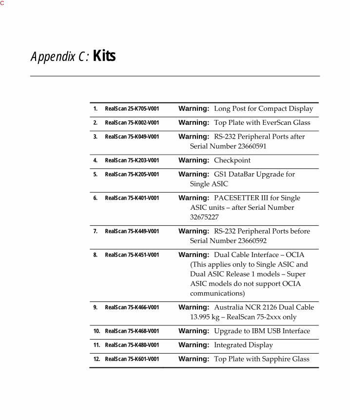
Appendix C: Kits
1. RealScan 25-K705-V001 Warning: Long Post for Compact Display
2. RealScan 75-K002-V001 Warning: Top Plate with EverScan Glass
3. RealScan 75-K049-V001 Warning: RS‐232 Peripheral Ports after Serial Number 23660591
4. RealScan 75-K203-V001 Warning: Checkpoint
5. RealScan 75-K205-V001 Warning: GS1 DataBar Upgrade for Single ASIC
6. RealScan 75-K401-V001 Warning: PACESETTER III for Single ASIC units – after Serial Number 32675227
7. RealScan 75-K449-V001 Warning: RS‐232 Peripheral Ports before Serial Number 23660592
8. RealScan 75-K451-V001 Warning: Dual Cable Interface – OCIA (This applies only to Single ASIC and Dual ASIC Release 1 models – Super ASIC models do not support OCIA communications)
9. RealScan 75-K466-V001 Warning: Australia NCR 2126 Dual Cable 13.995 kg – RealScan 75‐2xxx only
10. RealScan 75-K468-V001 Warning: Upgrade to IBM USB Interface
11. RealScan 75-K480-V001 Warning: Integrated Display
12. RealScan 75-K601-V001 Warning: Top Plate with Sapphire Glass
C

C-2 Appendix C: Kits
13. RealScan 75-K605-V001 Warning: Compact Sapphire Top Plate
14. RealScan 75-K702-V001 Warning: PACESETTER III for Dual ASIC units – before Serial Number 32675228
15. RealScan 75-K706-V001 Warning: Dual Cable Interface – RS‐232, ICL, MDL, SASI
16. RealScan 75-K968-V001 Warning: Upgrade to IBM USB Interface with Cable 1416‐C551‐0050
17. RealScan 80-K107-V002 Warning: Communications Adapter for RS‐232 and 4‐Bit Parallel Scale Interface

Appendix D: Scale Calibration Procedures
The instructions on the following page are included for personnel who are fully familiar with the calibration process. This form (497‐0449446) is also included in the box with each scanner/scale model.
D

D-2 Appendix D: Scale Calibration Procedures
Exercise the Scale Power‐on the scale for 30 minutes prior to calibration. Assure the scale is level and sitting upon four solid points of contact in a vibration‐free check stand with no airflow overhead. Exercise the scale to guarantee success by pushing on the top plate until it bottoms out and counting for 2 seconds then releasing the force. Push down on the top plate and count to 2 and release again.
Calibrate the Scale
Remove the Top Plate to access and remove the security cover, and depress the calibration button. Replace the Top Plate back onto the scale. The scale firmware controls the calibration procedure, waiting for your Scale Zero button depression before going to the next step. The voice and display identify what weights to place next onto the Top Plate. Put the required weight on the Top Plate (wait 1 second), and press the Scale Zero button. A single tone will sound prompting you to go to the next step. You can end the calibration procedure before completing it by turning the unit off. If you abort in this way, you must still calibrate the scale before placing it into service.
22829B
PEEL OFF ALL PROTECTIVE COATING FROM TOP PLATE PRIOR TO CALIBRATION. If the scale is equipped with an Electronic Article Surveillance (EAS), check for proper fit and alignment. TURN OFF THE EAS SYSTEM DURING CALIBRATION. Place weights in circles shown when calibrating to ensure even distribution of weight during calibration. Start in the center and work outward horizontally with increasing weight. Do not scatter weights around Top Plate.

Appendix D: Scale Calibration Procedures D-3
Verify the Scale
Place Scale in Service Note: A Weights & Measures (W&M) Seal may be needed.
When you perform a scale calibration, W&M officials may be required to attach a seal to the scale calibration security cover. Be sure to comply with local laws.
Note: In the United States and Canada, the audit trail serves as an acceptable security seal when the NCR RealScan 25 Display is present.
Place 5.00 kg (15.00 lb) on each of the 4 circles individually ‐ display must show 5.00 ± 0.005 kg (15.00 ± 0.01 lb.) with a max of 0.005 kg (0.01 lb.) between any of the 4 readings.
Remove all weights—display must read 0.000 ± 0.000 kg (0.00 ± 0.00 lb). Test max 30 lb in center only.
Press and hold the Scale Zero Button and record the Cal and PAr values shown on the display.
Note: Circles are ½ from Top Plate center
22829
EU Test Pattern