3. switched reluctance motors 3.1 introductionkaliasgoldmedal.yolasite.com/resources/sem/srm.pdf ·...
TRANSCRIPT

3. SWITCHED RELUCTANCE MOTORS
3.1 INTRODUCTION
The switched reluctance motor (SRM) drives for industrial applications are of recent
origin. Since 1969, a variable reluctance motor has been proposed for variable speed
applications. The origin of this motor can be traced back to 1842, but the “reinvention” has
been possible due to the advent of inexpensive, high-power switching devices. Even though
this machine is a type of synchronous machine, it has certain novel features.
3.2 CONSTRUCTION OF SWITCHED RELUCTANCE MOTOR
SRM are made up of laminated stator and rotor cores with Ns=2mq poles on the stator
and Nr poles on the rotor. The number of phases is m and each phase is made up of
concentrated coils place on 2q stator poles. Most favored configuration amongst many more
options are 6/4 three phase and 8/6 four phase SRM’s as shown in the figure 3.1(a).
These two configurations correspond to q=1(one pair of stator poles (and coils) per
phase) but q may be equal to 2, 3 when, for the three phase machine, we obtain 12/8 or 18/12
topologies applied either for low speed high torque direct drives or for high speed stator
generator systems for aircraft. The stator and rotor pole angles sβ and rβ are, in general,
almost equal to each other to avoid zero torque zones.
It has wound field coils of a dc motor for its stator windings and has no coils or
magnets on its rotor. Both the stator and rotor have salient poles, hence the machine is
referred to as a doubly salient machine. Such a typical machine is shown in Figure 3.1a, and
a modified version with two teeth per pole is shown in Figure 3.1b.
FIGURE 3.1 Switched reluctance motor configurations. (a) One tooth per pole.
(b) Two teeth per pole (12/10 poles).
The rotor is aligned whenever diametrically opposite stator poles are excited. In a
magnetic circuit, the rotating member prefers to come to the minimum reluctance position at
the instance of excitation. While two rotor poles are aligned to the two stator poles, another
set of rotor poles is out of alignment with respect to a different set of stator poles. Then, this
set of stator poles is excited to bring the rotor poles into alignment. Likewise, by sequentially
switching the currents into the stator windings, the rotor is rotated. The movement of the
rotor, hence the production of torque and power, involves switching of currents into stator
windings when there is a variation of reluctance; therefore, this variable speed motor drive is
referred to as a switched reluctance motor drive.
3.3 ADVANTAGES AND DISADVANATGES OF SRM
3.3.1 ADVANTAGES
The SRM possess a few unique features that makes it a vigorous competitor to existing AC
and DC motors in various adjustable-speed drive and servo applications. The advantages of
an SRM can be summarized as follows:
• Machine construction is simple and low-cost because of the absence of rotor
winding and permanent magnets.
• There are no shoot-through faults between the DC buses in the SRM drive converter
because each rotor winding is connected in series with converter switching
elements.
• Bidirectional currents are not necessary, which facilitates the reduction of the
number of power switches in certain applications.
• The bulk of the losses appear in the stator, which is relatively easier to cool.
• The torque–speed characteristics of the motor can be modified to the application
requirement more easily during the design stage than in the case of induction and PM
machines.
• The starting torque can be very high without the problem of excessive in-rush
current due to its higher self-inductance.
• The open-circuit voltage and short-circuit current at faults are zero or very small.
• The maximum permissible rotor temperature is higher, since there are no permanent
magnets.
• There is low rotor inertia and a high torque/inertia ratio.
• Extremely high speeds with a wide constant power region are possible.
• There are independent stator phases, which do not prevent drive operation in the case
of loss of one or more phases.

3.3.2 DISADVANTAGES
The SRM also comes with a few disadvantages among which torque ripple and
acoustic noise are the most critical. The higher torque ripple also causes the ripple current
in the DC supply to be quite large, necessitating a large filter capacitor. The doubly salient
structure of the SRM also causes higher acoustic noise compared with other machines.
The absence of permanent magnets imposes the burden of excitation on the stator
windings and converter, which increases the converter KVA requirement. Compared with
PM brushless machines, the per unit stator copper losses will be higher, reducing the
efficiency and torque per ampere. However, the maximum speed at constant power is not
limited by the fixed magnet flux as in the PM machine, and, hence, an extended constant
power region of operation is possible in SRMs.
3.4 APPLICATIONS OF SRM
The simple motor structure and inexpensive power electronic requirement have made the
SRM an attractive alternative to both AC and DC machines in adjustable-speed drives. Few
of such applications are listed below.
a) General purpose industrial drives;
b) Application-specific drives: compressors, fans, pumps, centrifuges;
c) Domestic drives: food processors, washing machines, vacuum cleaners;
d) Electric vehicle application;
e) Aircraft applications;
f) Servo-drive.
3.5 ELEMENTARY OPERATION OF THE SWITCHED RELUCTANCE MOTOR
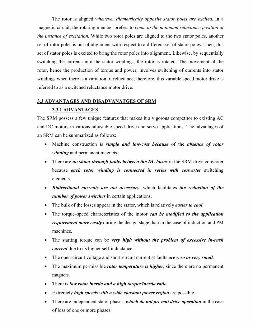
Consider that the rotor poles '
11 and rr and stator poles 'c and c are aligned. Apply a
current to phase a with the current direction as shown in Figure 3.2a. A flux is established
through stator poles ' and aa and rotor poles '
22 and rr which tends to pull the rotor poles
'
22 and rr toward the stator poles ' and aa , respectively. When they are aligned, the stator
current of phase a is turned off and the corresponding situation is shown in Figure 3.2b. Now
the stator winding b is excited, pulling '
11 and rr toward ' and bb in a clockwise direction.
Likewise, energization of the c phase winding results in the alignment of '
22 and rr with
' and cc , respectively. Hence, it takes three phase energizations in sequence to move the rotor
by 900
and one revolution of rotor movement is effected by switching currents in each phase
as many times as there are number of rotor poles. The switching of currents in the sequence
acb results in the reversal of rotor rotation is seen with the aid of Figures 3.2a and b.
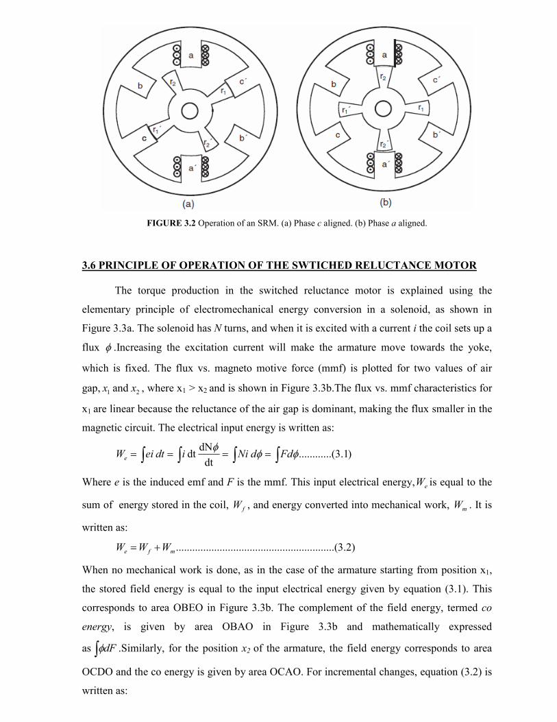
FIGURE 3.2 Operation of an SRM. (a) Phase c aligned. (b) Phase a aligned.
3.6 PRINCIPLE OF OPERATION OF THE SWTICHED RELUCTANCE MOTOR
The torque production in the switched reluctance motor is explained using the
elementary principle of electromechanical energy conversion in a solenoid, as shown in
Figure 3.3a. The solenoid has N turns, and when it is excited with a current i the coil sets up a
flux φ .Increasing the excitation current will make the armature move towards the yoke,
which is fixed. The flux vs. magneto motive force (mmf) is plotted for two values of air
gap, 21 and xx , where x1 > x2 and is shown in Figure 3.3b.The flux vs. mmf characteristics for
x1 are linear because the reluctance of the air gap is dominant, making the flux smaller in the
magnetic circuit. The electrical input energy is written as:
∫ ∫∫∫ ==== )1.3..(.......... dt
dNdt φφ
φFddNiidteiWe
Where e is the induced emf and F is the mmf. This input electrical energy, eW is equal to the
sum of energy stored in the coil, fW , and energy converted into mechanical work, mW . It is
written as:
)2.3........(..................................................mfe WWW +=
When no mechanical work is done, as in the case of the armature starting from position x1,
the stored field energy is equal to the input electrical energy given by equation (3.1). This
corresponds to area OBEO in Figure 3.3b. The complement of the field energy, termed co
energy, is given by area OBAO in Figure 3.3b and mathematically expressed
as ∫ dFφ .Similarly, for the position x2 of the armature, the field energy corresponds to area
OCDO and the co energy is given by area OCAO. For incremental changes, equation (3.2) is
written as:
)3.3...(..................................................mfe WWW δδδ +=
For a constant excitation of F1 given by the operating point A in Figure 3.3b, the various
energies are derived as:
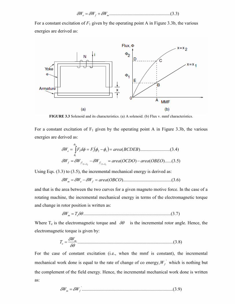
FIGURE 3.3 Solenoid and its characteristics. (a) A solenoid. (b) Flux v. mmf characteristics.
For a constant excitation of F1 given by the operating point A in Figure 3.3b, the various
energies are derived as:
( )
)5.3)......(()(
)4.3.......(..........).........(
12
2
1
1211
OBEOareaOCDOareaWWW
BCDEBareaFdFW
XXXXfff
e
−=−=
=−==
==
∫δδδ
φφφδφ
φ
Using Eqs. (3.3) to (3.5), the incremental mechanical energy is derived as:
)6.3...(..............................).........(OBCOareaWWW fem =−= δδδ
and that is the area between the two curves for a given magneto motive force. In the case of a
rotating machine, the incremental mechanical energy in terms of the electromagnetic torque
and change in rotor position is written as:
)7.3......(......................................................................δθδ em TW =
Where Te is the electromagnetic torque and δθ is the incremental rotor angle. Hence, the
electromagnetic torque is given by:
)8.3...(................................................................................δθδ m
e
WT =
For the case of constant excitation (i.e., when the mmf is constant), the incremental
mechanical work done is equal to the rate of change of co energy,'
fW which is nothing but
the complement of the field energy. Hence, the incremental mechanical work done is written
as:
)9.3.........(......................................................................'
fm WW δδ =

Where
( ) ( ) ( ) ( )∫ ∫∫∫ ∫ ===== )10.3(..........,,'
idiiLdiidiNNiddFW f θθλφφφ
Where the inductance, L, and flux linkages, λ, are functions of the rotor position and current.
This change in co energy occurs between two rotor positions, θ2 and θ1. Hence, the air gap
torque in terms of the co energy represented as a function of rotor position and current is
( ))11.3(....................
,
constanti
''
=
===δθ
θδ
δθ
δ
δθδ iWWW
Tffm
e
If the inductance is linearly varying with rotor position for a given current, which in general
is not the case in practice, then the torque can be derived as:
( )
( ) ( ) ( ))13.3..(..............................
,,,
)12.3(............................................................2
.,
constanti12
12
2
=−−
=
=
θθθθ
θθ
θθ
iLiL
d
idL
Where
i
d
idLTe
and this differential inductance can be considered to be the torque constant expressed in N.
m/A2. It is important to emphasize at this juncture that this is not a constant and that it varies
continuously. This has the implication that the switched reluctance motor will not have a
steady-state equivalent circuit in the sense that the dc and ac motors have.
The following are the implications of equation (3.12)
1. The torque is proportional to the square of the current; hence the current can be
unipolar to produce unidirectional torque. Note that this is quite contrary to the
case for ac machines. This unipolar current requirement has a distinct advantage in
that only one power switch is required for control of current in a phase winding.
Such a feature greatly reduces the number of power switches in the converter and
thereby makes the drive economical.
2. The torque constant is given by the slope of the inductance vs. rotor position
characteristic. It is understood that the inductance of a stator winding is a function
of both the rotor position and current, thus making it nonlinear. Because of its
nonlinear nature, a simple equivalent circuit development for this motor is not
possible.
3. Since the torque is proportional to the square of the current, this machine resembles
a dc series motor; hence, it has a good starting torque.
4. A generating action is made possible with unipolar current due to its operation on
the negative slope of the inductance profile.
5. The direction of rotation can be reversed by changing the sequence of stator
excitation, which is a simple operation.
3.7 COMPARISION BETWEEN SRM AND STEPPER MOTORS
From the above description, it is deduced that the switched reluctance motor is similar to the
step motor except that it has
1. Fewer poles
2. Larger stepping angle
3. Usually one tooth per pole
4. Higher power output capability
5. The SRM motor is normally operated with shaft position feed back to
synchronize the commutation of the phase currents with precise rotor
positions, where as stepper motor is normally run in open loop, i.e with out
shaft position feed back.
6. SRM is normally designed for efficient conversion of significant amounts of
power, stepper motors are more usually designed to maintain step integrity in
position controls.
The comparison should not be carried too much further due to the nonlinearity of the
magnetic circuit.
3.8 DERIVATION OF THE RELATIONSHIP BETWEEN INDUCTANCE AND
ROTOR POSITION-NON LINEAR ANALYSIS
Since the torque characteristics are dependent on the relationship between flux
linkages and rotor position as a function of current, it is worthwhile to conceptualize the
control possibilities and limitations of this motor drive. For example, a typical phase
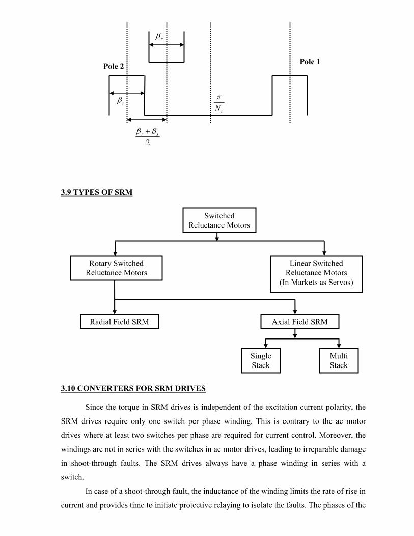
inductance vs. rotor position is shown in Figure 3.4 for a fixed phase current. The inductance
corresponds to that of a stator-phase coil of the switched reluctance motor neglecting the
fringe effect and saturation. The significant inductance profile changes are determined in
terms of the stator and rotor pole arcs and number of rotor poles. The rotor pole arc is
assumed to be greater than the stator pole arc for this illustration, which is usually the case.
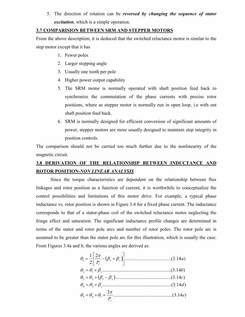
From Figures 3.4a and b, the various angles are derived as:
( )
( )
)14.3.........(........................................2
)14.3.......(..................................................
)14.3.......(........................................
)14.3.......(..................................................
)14.3.........(..............................2
2
1
145
34
23
12
1
eP
d
c
b
aP
r
s
sr
s
rs
r
πθθθ
βθθ
ββθθ
βθθ
ββπ
θ
=+=
+=
−+=
+=
+−=

Where βs and βr are stator and rotor pole arcs, respectively, and Pr is the number of rotor
poles.
Four distinct inductance regions emerge:
1. 0 − θ1 and θ4 − θ5: The stator and rotor poles are not overlapping in this region and
the flux is predominantly determined by the air path, thus making the inductance
minimum and almost a constant. Hence, these regions do not contribute to torque
production. The inductance in this region is known as unaligned inductance, Lu.
FIGURE 3.4 Derivation of inductance vs. rotor position from rotor and stator pole arcs for an unsaturated
switched reluctance machine. (a) Basic rotor position definition in a two pole SRM. (b) Inductance profile.
2. θ1 − θ2: Poles overlap, so the flux path is mainly through stator and rotor laminations.
This increases the inductance with the rotor position, giving it a positive slope. A
current impressed in the winding during this region produces a positive (i.e.,
motoring) torque. This region comes to an end when the overlap of poles is complete.
3. θ2 − θ3: During this period, movement of rotor pole does not alter the complete
overlap of the stator pole and does not change the dominant flux path. This has the

effect of keeping the inductance maximum and constant, and this inductance is
known as aligned inductance, La. As there is no change in the inductance in this
region, torque generation is zero even when a current is present in this interval. In
spite of this fact, it serves a useful function by providing time for the stator current to
come to zero or lower levels when it is commutated, thus preventing negative torque
generation for part of the time if the current has been decaying in the negative slope
region of the inductance.
4. θ3 − θ4: The rotor pole is moving away from overlapping the stator pole in this region.
This is very much similar to the θ1 − θ2 region, but it has decreasing inductance and
increasing rotor position contributing to a negative slope of the inductance region.
The operation of the machine in this region results in negative torque (i.e., generation
of electrical energy from mechanical input to the switched reluctance machine).
It is not possible to achieve the ideal inductance profiles shown in Figure 3.4 in an actual
motor due to saturation. Saturation causes the inductance profile to curve near the top and
thus reduces the torque constant. Hence, saturating the machine beyond a point produces a
diminishing return on torque and power output.
DETAILED DERIVATION
Let LA be the aligned inductance of a coil/Phase and LU be the unaligned inductance of the
coil / phase. βs and βr are stator and rotor pole arcs, respectively. Let us assume that βr > βs
and LA > LU.
Case 1: When θ=00
Axis of the stator pole is in alignment with the stator pole as shown in the figure below.
Therefore the inductance of the coil is LA, because the stator reference axis and rotor
reference axis are in alignment. At this position flux linkage of phase winding of stator has
maximum value and hence inductance of phase winding has maximum value for given
current.

CASE II: When 2
sr ββθ
−=
The rotor reference axis makes angular displacement of 2
sr ββ − stator reference axis one
edge of rotor pole is along the edge of stator pole. At this position reluctance is minimum.
Then the inductance of the coil continues to be LA. When θ varies from 0 to2
sr ββ −. At this
position also L=LA.
CASE III: WHEN 2
sr ββθ
+=
Pole pitch of the rotor = rN
π2
Half the pole pitch of the rotor = rN
π Assume
r
sr
N
πββθ <
+=
2
In this position, the flux pattern is such that the flux linkages / unit current of the stator is less
than the previous case but not minimum. Therefore L < LA and L > LU.
LU < L < LA 22
srsr ββθ
ββ +<<
− At
L=LA

CASE IV: WHEN rN
πθ =
For r
sr
N
πθ
ββ≤≤
+2
CASE V: WHEN r
sr
N
πββθ after
2
+= (or)
2
2 sr
rN
ββπθ
+−= as far as the rotor pole is
considered. After which stator pole comes under the influence of the rotor pole 2. Now the
inductance variation is from LU to LA as the rotor pole moves towards so as to cover the
stator pole.
L=LU
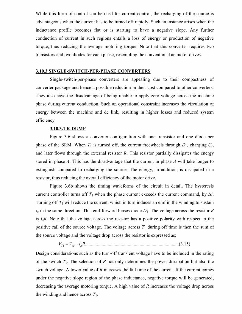
3.9 TYPES OF SRM
3.10 CONVERTERS FOR SRM DRIVES
Since the torque in SRM drives is independent of the excitation current polarity, the
SRM drives require only one switch per phase winding. This is contrary to the ac motor
drives where at least two switches per phase are required for current control. Moreover, the
windings are not in series with the switches in ac motor drives, leading to irreparable damage
in shoot-through faults. The SRM drives always have a phase winding in series with a
switch.
In case of a shoot-through fault, the inductance of the winding limits the rate of rise in
current and provides time to initiate protective relaying to isolate the faults. The phases of the
rN
π rβ
sβ
Pole 2 Pole 1
Switched
Reluctance Motors
Rotary Switched
Reluctance Motors
Linear Switched
Reluctance Motors
(In Markets as Servos)
Radial Field SRM Axial Field SRM
Single
Stack
Multi
Stack
2
sr ββ +

SRM are independent and, in case of one winding failure, uninterrupted operation of the
motor drive operation is possible, although with reduced power output.
3.10.1 CONVERTER CONFIGURATIONS
The mutual coupling between phases is negligible in SRMs. This gives complete
independence to each phase winding for control and torque generation. While this feature is
advantageous, a lack of mutual coupling requires a careful handling of the stored magnetic
field energy. The magnetic field energy has to be provided with a path during commutation
of a phase; otherwise, it will result in excessive voltage across the windings and hence on the
power semiconductor switches leading to their failure. The manner in which this energy is
handled gives way to unique but numerous converter topologies for SRM drives. The energy
could be freewheeled, partially converting it to mechanical/electrical energy and partially
dissipating it in the machine windings. Another option is to return it to the dc source either by
electronic or electromagnetic means. All of these options have given way to power converter
topologies with q, (q+1), 1.5q, and 2q switch topologies, where q is the number of machine
phases.
3.10.1.1 Classification of Converter Configurations
3.10.2 ASYMMETRIC BRIDGE CONVERTER
Figure 3.5a shows the asymmetric bridge converter considering only one phase of the SRM.
The rest of the phases are similarly connected. Turning on transistors T1 and T2 will circulate
a current in phase A of the SRM. If the current rises above the commanded value, T1 and T2
Converter Configuration for q phase SRM
Two Stage
Power
Converters
Two-
Switch/phase
(2q switch)
1.5-
Switch/phase
(1.5q switch)
(q+1) Switch Single
Switch/Phase
q Switch
� Equal Sharing
� C-Dump
� C-Dump with free wheeling
� Shared Switch
� Minimum switch with variable
DC link with Front end
� Resonant
� R-Dump
� Bifilar
� Split DC
supply
� Asymmetric
� Variation of Asymmetric with
higher than 2q Switches

are turned off. The energy stored in the motor winding of phase A will keep the current in the
same direction until it is depleted. Hence, diodes D1 and D2 will become forward biased
leading to recharging of the source. That will decrease the current, rapidly bringing it below
the commanded value. This operation is explained with the waveforms of Figure 3.5b.
Assuming that a current of magnitude Ip is desired during the positive inductance slope for
motoring action, the A -phase current command is generated with a linear inductance profile.
Here, phase advancing both at the beginning and during commutation are neglected. The
current command *
ai is enforced with a current feedback loop where it is compared with the
phase current, ia. The current error is presumed to be processed through a hysteresis
controller with a current window of ∆i. When the current error exceeds −∆i, the switchesT1
and T2 are turned off simultaneously. Hysteresis current controller is considered here due to
its simplicity in concept and implementation. At that time, diodes, D1 and D2 take over the
current and complete the path through the dc source.
FIGURE 3.5 (a) Asymmetric converter for SRM with freewheeling and regeneration capability.
Note that the voltage of phase A is then negative and will equal the source voltage,
Vdc. During this interval, the energy stored in the machine inductance is sent to the source,
thus exchanging energy between the load and source repeatedly in one cycle of a phase
current. After the initial startup, during turn-on and turn-off of T1 and T2, the machine phase
winding experiences twice the rate of change of dc link voltage, resulting in a higher
deterioration of the insulation. This control strategy (strategy I) hence puts more ripples into
the dc link capacitor, thus reducing its life and also increasing the switching losses of the
power switches due to frequent switching necessitated by energy exchange. These can be
ameliorated with an alternate switching strategy.

FIGURE 3.5 (b) Operational waveforms of the asymmetric bridge converter (strategy I);
(c) Operational waveforms of the asymmetric bridge converter (strategy II).
The energy stored in the phase A can be effectively circulated in itself by turning off, say, T2
only (strategy II). In that case, the current will continue to flow through T1, phase A, and D1,
the latter having forward biased soon after T2 is turned off. The voltage across the winding
becomes zero if the diode and transistor voltage drops are neglected as shown in Figure 4.2c.
That will take the phase current from Ip +∆I to Ip −∆i in a time greater than had it been
forced against the source voltage using the previous strategy. This particular fact reduces the
switching frequency and hence the switching losses. When the current command goes to
zero, both T1 and T2 are turned off simultaneously. During this interval, the voltage across the
winding is −Vdc as long as D1 and D2 conduct (i.e., until ia goes to zero) and thereafter the
winding voltage is zero. The voltage across T2 during its off time and when T1 is on is equal
to the source voltage, Vdc. Hence, the power switches and diodes have to be rated to a
minimum of source voltage at least. The current ratings of the switches are equal to or less
than qI p by interchanging the off times between T1 and T2 in one cycle of phase
conduction. Similarly, the current rating of the diodes can be evaluated. While such a self-
circulation will keep the current going for a longer time compared to recharging the source
voltage, it has the advantage of converting the stored energy to useful mechanical work.
While this form of control can be used for current control, the recharging of the source is
advantageous when the current has to be turned off rapidly. Such an instance arises when the
inductance profile becomes flat or is starting to have a negative slope. Any further
conduction of current in such regions entails a loss of energy or production of negative
torque, thus reducing the average motoring torque. Note that this converter requires two
transistors and two diodes for each phase, resembling the conventional ac motor drives.
3.10.3 SINGLE-SWITCH-PER-PHASE CONVERTERS
Single-switch-per-phase converters are appealing due to their compactness of
converter package and hence a possible reduction in their cost compared to other converters.
They also have the disadvantage of being unable to apply zero voltage across the machine
phase during current conduction. Such an operational constraint increases the circulation of
energy between the machine and dc link, resulting in higher losses and reduced system
efficiency
3.10.3.1 R-DUMP
Figure 3.6 shows a converter configuration with one transistor and one diode per
phase of the SRM. When T1 is turned off, the current freewheels through D1, charging Cs,
and later flows through the external resistor R. This resistor partially dissipates the energy
stored in phase A. This has the disadvantage that the current in phase A will take longer to
extinguish compared to recharging the source. The energy, in addition, is dissipated in a
resistor, thus reducing the overall efficiency of the motor drive.
Figure 3.6b shows the timing waveforms of the circuit in detail. The hysteresis
current controller turns off T1 when the phase current exceeds the current command, by ∆i.
Turning off T1 will reduce the current, which in turn induces an emf in the winding to sustain
ia in the same direction. This emf forward biases diode D1. The voltage across the resistor R
is iaR. Note that the voltage across the resistor has a positive polarity with respect to the
positive rail of the source voltage. The voltage across T1 during off time is then the sum of
the source voltage and the voltage drop across the resistor is expressed as:
)15.3.........(......................................................................1 RiVV adcT +=
Design considerations such as the turn-off transient voltage have to be included in the rating
of the switch T1. The selection of R not only determines the power dissipation but also the
switch voltage. A lower value of R increases the fall time of the current. If the current comes
under the negative slope region of the phase inductance, negative torque will be generated,
decreasing the average motoring torque. A high value of R increases the voltage drop across
the winding and hence across T1.

FIGURE 3.6 (a) Converter for SRM with freewheeling path; (b) operational waveforms of R-dump converter
3.10.3.2 BIFILAR TYPE
Figure 3.7a shows a converter configuration with one transistor and one diode per phase but
regenerating the stored magnetic energy to the source. This is achieved by having a bifilar
winding with the polarity as shown in the figure. When the phase-A current is turned off by
removing the base drive signal to T1, the induced emf in the winding is of such polarity that

D1 is forward biased. This leads to the circulation of current through D1, the bifilar secondary
winding, and the source, thus transferring energy from the machine winding to the source.
The various timing waveforms of the circuit are shown in Figure 3.7b. During current turn-
off, the applied voltage across the bifilar secondary winding is equal to the dc link voltage.
The voltage reflected into the main winding is dependent upon the turns ratio of the
windings. Considering the turns ratio between the main winding in series with the power
switch and the auxiliary winding in series with the diode as a, the voltage across the power
switch is
( ) )16.3(......................................................................11 dcdcdcT VaaVVV +=+=
This shows that the voltage across T1 can be very much greater than the source voltage. One
switch per phase comes with a voltage penalty on the switch. The volt ampere (VA)
capability of the switch will not be very different for one switch compared to two switches
per phase circuit. The disadvantage of this drive is that the SRM needs a bifilar winding and
such a form of winding is not economical for large motors. Also, the bifilar windings require
additional slot volume, reducing the power density of the SRM.
FIGURE 3.7 (a) Converter for an SRM with bifilar windings

FIGURE 3.7 (b) operational waveforms of bifilar converter.
3.10.3.3 SPLIT DC SUPPLY CONVERTER
A split dc supply for each phase allows freewheeling and regeneration, as shown in
Figure 3.8a. This topology preserves one switch per phase; its operation is as follows. Phase
A is energized by turning on T1. The current circulates through T1, phase A, and capacitor C1.
When T1 is turned off, the current will continue to flow through phase A, capacitor C2, and
diode D2. In that process, C2 is being charged up and hence the stored energy in phase A is
depleted quickly. Similar operation follows for phase B. The operation of this circuit for
phase A is shown in Figure 3.8b. A hysteresis current controller with a window of ∆i is
assumed. The phase voltage is Vdc /2 when T1 is on, and when it is turned off with a current
established in phase A, the phase voltage is –Vdc/2. The voltage across the transistor T1 during
the on time is negligible, and it is Vdc when the current is turned off. That makes the switch
voltage rating at least equal to the dc link voltage. As the stator current reference, goes to
zero, the switch T1 is turned off regardless of the magnitude of ia. When the winding current
becomes zero, the voltage across T1 drops to 0.5 Vdc and so also does the voltage across D2.
Note that this converter configuration has the disadvantage of derating the supply dc voltage,

Vdc, by utilizing only half its value at any time. Moreover, care has to be exercised in
balancing the charge of C1 and C2 by proper design measures.
FIGURE 3.8 (a) Converter for SRM with split dc supply; (b) Operational waveforms of split dc supply
converter.
For balancing the charge across the dc link capacitors, the number of machine phases
has to be even and not odd. In order to improve the cost-competitive edge of the SRM drive,
this converter was chosen in earlier integral horse power (hp) product developments, but its
use in fractional hp SRM drives supplied by a single phase 120-V ac supply is much more

justifiable; the neutral of the ac supply is tied to the midpoint of the dc link and so capacitors
can be rated to 200 V dc, thus minimizing the cost of the converter.
3.10.4 (q + 1) SWITCH AND DIODE CONFIGURATIONS
3.10.4.1 C-DUMP CONVERTER
The C-dump converter is shown in figure 3.9 with an energy recovery circuit. The
stored magnetic energy is partially diverted to the capacitor Cd and recovered from it by the
single quadrant chopper comprising of Tr, Lr, and Dr and sent to the dc source. Assume that
T1 is turned on to energize phase A and when the A-phase current exceeds the reference, T1 is
turned off. This enables the diode D1 to be forward biased, and the current path is closed
through Cd which increases the voltage across it. This has the effect of reducing the A-phase
current, and, when the current falls below the reference by ∆i (i.e., current window), T1 is
turned on to maintain the current close to its reference. When current has to be turned off
completely in phase A, T1 is turned off, and partially stored magnetic energy in phase A is
transferred to energy dump capacitor, Cd. The remaining magnetic energy in the machine
phase has been converted to mechanical energy. Figure 3.9(b) shows the variables of interest
in this converter.
This converter has the advantage of minimum switches allowing independent phase
current control. The main disadvantage of this circuit is that the current commutation is
limited by the difference between voltage across Cd, vo, and the dc link voltage. Speedy
commutation of currents requires larger vo, which results in increasing the voltage rating of
the power devices. Further, the energy circulating between Cd and the dc link results in
additional losses in the machine, Tr, Lr, and Dr, there by decreasing the efficiency of the
motor drive.
The energy recovery circuit is activated only when T1, T2, T3 orT4 switches are
conducting to avoid freewheeling of the phase currents. The control pulses to Tr end with the
turn-off of the phase switches. The control pulse is generated based on the reference and
actual value of E with a window of hysteresis to minimize the switching of Tr.

FIGURE 3.9 (a) C-dump converter with energy recovery circuit;
(b) Waveforms of C-dump converter with energy-recovery circuit.
3.11 MICROPROCESSOR BASED CONTROL OF SRM
This section describes a general purpose microprocessor controlled closed loop-
switched reluctance motor (SRM) drive system. The system is designed to drive a four phase
SRM with minimum number of switches, while achieving maximum flexibility. This section
also describes the hardware for driving the motor, the techniques used to measure control
parameters and how they are fed to the microprocessor. The operation of the microprocessor
software to provide the user interface and control on the operation is given in detail.
The main objective of this microprocessor based control of SRM is to develop
Software controllability of various modes of operation; here a microprocessor based control
philosophy is adopted to achieve flexibility of adapting the controller-driver for various
applications.
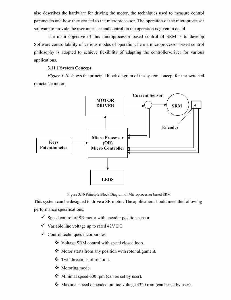
3.11.1 System Concept
Figure 3-10 shows the principal block diagram of the system concept for the switched
reluctance motor.
Figure 3.10 Principle Block Diagram of Microprocessor based SRM
This system can be designed to drive a SR motor. The application should meet the following
performance specifications:
� Speed control of SR motor with encoder position sensor
� Variable line voltage up to rated 42V DC
� Control techniques incorporates
� Voltage SRM control with speed closed loop.
� Motor starts from any position with rotor alignment.
� Two directions of rotation.
� Motoring mode.
� Minimal speed 600 rpm (can be set by user).
� Maximal speed depended on line voltage 4320 rpm (can be set by user).
MOTOR
DRIVER
SRM
Micro Processor
(OR)
Micro Controller
Keys
Potentiometer
s
LEDS
Current Sensor
Encoder
POTENTIOMETER
Speed
Command
Duty
Cycle Speed
Error SPEED
CONTROLLER
PWM
GENERATION
LOW SIDE
BIT PATTERN
COMMUTATION
ANGLE
CALCULATION
SPEED
CALCULATION
16 BIT UP/DOWN
COUNTER
EXTERNAL
INTERUPT
ADC
MOTOR
DRIVER M
Encoder
KEYs, LEDs ADC
� Encoder position reference for commutation.
� User Interface (start/stop switch, right/left switch, potentiometer for speed
adjustment, LED indicators).
� DC-Bus over current protection.
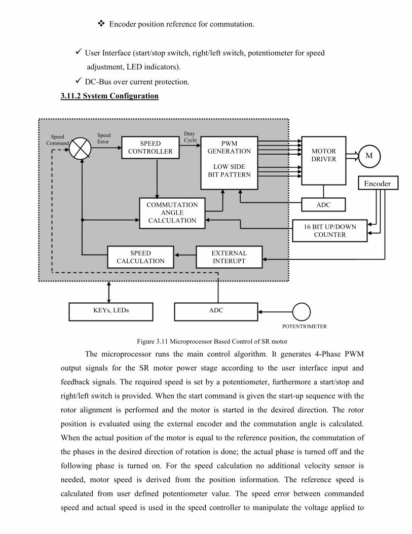
3.11.2 System Configuration
Figure 3.11 Microprocessor Based Control of SR motor
The microprocessor runs the main control algorithm. It generates 4-Phase PWM
output signals for the SR motor power stage according to the user interface input and
feedback signals. The required speed is set by a potentiometer, furthermore a start/stop and
right/left switch is provided. When the start command is given the start-up sequence with the
rotor alignment is performed and the motor is started in the desired direction. The rotor
position is evaluated using the external encoder and the commutation angle is calculated.
When the actual position of the motor is equal to the reference position, the commutation of
the phases in the desired direction of rotation is done; the actual phase is turned off and the
following phase is turned on. For the speed calculation no additional velocity sensor is
needed, motor speed is derived from the position information. The reference speed is
calculated from user defined potentiometer value. The speed error between commanded
speed and actual speed is used in the speed controller to manipulate the voltage applied to

each phase winding and the firing angles. As mentioned earlier PWM Voltage regulation is
used in low- and mid speed regions, whereas advancing the turn-on angle in the single-pulse
control comes active in the high speed area. The control algorithm is build up in such a
matter, when the PWM regulation reaches its limits the single-pulse regulation takes over.
Then during the PWM cycle, the actual phase current is compared with the absolute
maximum value for the rated current. As soon as the actual current exceeds this value the
PWM duty cycle is restricted. The procedure is repeated for each commutation cycle of the
motor.
3.12 Torque–Speed Characteristics
The torque–speed plane of an SRM drive can be divided into three regions as shown in Fig.
3.12. The constant torque region is the region below the base speed ωb, which is defined as
the highest speed when maximum rated current can be applied to the motor at rated voltage
with fixed firing angles. In other words, ωb is the lowest possible speed for the motor to
operate at its rated power.
Region 1
In the low-speed region of operation, the current rises almost instantaneously after turn-on,
since the back-emf is small. The current can be set at any desired level by means of
regulators, such as hysteresis controller or voltage PWM controller.
As the motor speed increases, the back-emf soon becomes comparable to the DC bus
voltage and it is necessary to phase advance-the turn-on angle so that the current can rise up
to the desired level against a lower back-emf. Maximum current can still be forced into the
motor by PWM or chopping control to maintain the maximum torque production. The phase
excitation pulses are also needed to be turned off a certain time before the rotor passes
alignment to allow the freewheeling current to decay so that no braking torque is produced.
Fig 3.12 Torque Speed Characteristics of SRM

Region 2
When the back-emf exceeds the DC bus voltage in high-speed operation, the current starts to
decrease once pole overlap begins and PWM or chopping control is no longer possible. The
natural characteristic of the SRM, when operated with fixed supply voltage and fixed
conduction angle θdwell (also known as the dwell angle), is that the phase excitation time falls
off inversely with speed and so does the current. Since the torque is roughly proportional to
the square of the current, the natural torque–speed characteristic can be defined by T α 1/ω2.
Increasing the conduction angle can increase the effective amps delivered to the phase. The
torque production is maintained at a level high enough in this region by adjusting the
conduction angle θdwell with the single-pulse mode of operation. The controller maintains the
torque inversely proportional to the speed; hence, this region is called the constant power
region. The conduction angle is increased by advancing the turn-on angle until the θ dwell
reaches its upper limit at speed ωp. The medium speed range through which constant power
operation can be maintained is quite wide and very high maximum speeds can be achieved.
Region 3
The θdwell upper limit is reached when it occupies half the rotor pole-pitch, i.e., half the
electrical cycle. θdwell cannot be increased further because otherwise the flux would not return
to zero and the current conduction would become continuous. The torque in this region is
governed by the natural characteristics, falling off as 1/ω2. The torque–speed characteristics
of the SRM are similar to those of a DC series motor, which is not surprising considering that
the back-emf is proportional to current, and the torque is proportional to the square of the
current.
3.13 SR MOTOR CONTROL
For motoring operation the pulses of phase current must coincide with a period of increasing
inductance, i.e. when a pair of rotor poles is approaching alignment with the stator poles of
the excited phase. The timing and dwell of the current pulse determine the torque, the
efficiency, and other parameters. In d.c. and brushless d.c. motors the torque per ampere is
more or less constant, but in the SR. motor no such simple relationship emerges naturally.
With fixed firing angles, there is a monotonic relationship between average torque and r.m.s.
phase current, but in general it is not very linear. This may present some complications in
feedback-controlled systems although it does not prevent the SR motor from achieving 'near-
servo quality' dynamic performance, particularly in respect of speed range, torque/inertia, and
reversing capability.

At low speeds the self-e.m.f. of the winding is small and the current must be limited by
chopping or p.w.m. of the applied voltage. The regulating strategy employed has a marked
effect on the performance and the operating characteristics.
3.13.1 Hysteresis Type Regulator
Figure 3.13(a) shows schematically the method of control. As the current reference
increases, the torque increases. At low currents the torque is roughly proportional to current
squared, but at higher currents it becomes more nearly linear. At very high currents saturation
decreases the torque per ampere again. This type of control produces a constant-torque type
of characteristic as indicated in Fig. 3.14. With loads whose torque increases monotonically
with speed, such as fans and blowers, speed adjustment is possible without tachometer
feedback, but in general feedback is needed to provide accurate speed control. In some cases
the pulse train from the shaft position sensor may be used for speed feedback, but only at
relatively high speeds. At low speeds a larger number of pulses per revolution is necessary,
and this can be generated by an optical encoder or resolver, or alternatively by phase-locking
a high-frequency oscillator to the pulses of the commutation sensor (Bose 1986). Systems
with resolver-feedback or high-resolution optical encoders can work right down to zero
speed. The 'hysteresis-type' current regulator may require current transducers of wide
bandwidth, but the SR drive has the advantage that they can be grounded at one end, with the
other connected to the negative terminal of the lower phase leg switch. Shunts or Hall-effect
sensors can be used, or alternatively, 'Sensefets' with in-built current sensing. Much of the
published literature on SR drives describes this form of control.
Fig 3.13 Schematic of Current regulated for one Phase
(a) Hysteresis Type (b) Voltage PWM Type (duty-cycle control)
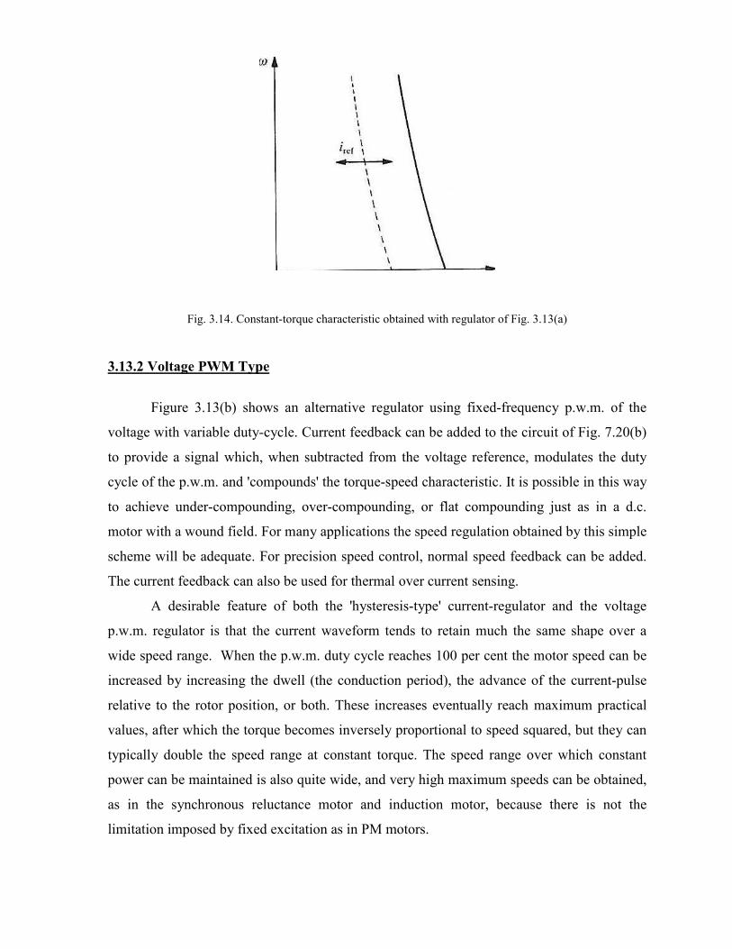
Fig. 3.14. Constant-torque characteristic obtained with regulator of Fig. 3.13(a)
3.13.2 Voltage PWM Type
Figure 3.13(b) shows an alternative regulator using fixed-frequency p.w.m. of the
voltage with variable duty-cycle. Current feedback can be added to the circuit of Fig. 7.20(b)
to provide a signal which, when subtracted from the voltage reference, modulates the duty
cycle of the p.w.m. and 'compounds' the torque-speed characteristic. It is possible in this way
to achieve under-compounding, over-compounding, or flat compounding just as in a d.c.
motor with a wound field. For many applications the speed regulation obtained by this simple
scheme will be adequate. For precision speed control, normal speed feedback can be added.
The current feedback can also be used for thermal over current sensing.
A desirable feature of both the 'hysteresis-type' current-regulator and the voltage
p.w.m. regulator is that the current waveform tends to retain much the same shape over a
wide speed range. When the p.w.m. duty cycle reaches 100 per cent the motor speed can be
increased by increasing the dwell (the conduction period), the advance of the current-pulse
relative to the rotor position, or both. These increases eventually reach maximum practical
values, after which the torque becomes inversely proportional to speed squared, but they can
typically double the speed range at constant torque. The speed range over which constant
power can be maintained is also quite wide, and very high maximum speeds can be obtained,
as in the synchronous reluctance motor and induction motor, because there is not the
limitation imposed by fixed excitation as in PM motors.

TWO MARKS QUESTIONS AND ANSWERS
1. Define Switched Reluctance Motor
SRM is a doubly salient and singly excited motor. That means both the stator and rotor
has salient poles but only one usually stator carries the winding which operates based on the
reluctance principle.
2. Write two distinguished points between Switched Reluctance and stepper motor.
• The SRM motor is normally operated with shaft position feed back to synchronize the
commutation of the phase currents with precise rotor positions, where as stepper
motor is normally run in open loop, i.e. without shaft position feedback.
• SRM is normally designed for efficient conversion of significant amounts of power,
stepper motors are more usually designed to maintain step integrity in position
controls.
3. Write the advantages of SRM.
• Machine construction is simple and low-cost because of the absence of rotor
winding and permanent magnets.
• There are no shoot-through faults between the DC buses in the SRM drive converter
because each rotor winding is connected in series with converter switching
elements.
• Bidirectional currents are not necessary, which facilitates the reduction of the
number of power switches in certain applications.
• The bulk of the losses appear in the stator, which is relatively easier to cool.
• The torque–speed characteristics of the motor can be modified to the application
requirement more easily during the design stage than in the case of induction and PM
machines.
• The starting torque can be very high without the problem of excessive in-rush
current due to its higher self-inductance.
• The open-circuit voltage and short-circuit current at faults are zero or very small.
• The maximum permissible rotor temperature is higher, since there are no permanent
magnets.
• There is low rotor inertia and a high torque/inertia ratio.
• Extremely high speeds with a wide constant power region are possible.
• There are independent stator phases, which do not prevent drive operation in the case
of loss of one or more phases.
4. List the disadvantages of SRM.
• The SRM also comes with a few disadvantages among which torque ripple and
acoustic noise are the most critical. The higher torque ripple also causes the ripple
current in the DC supply to be quite large, necessitating a large filter capacitor. The
doubly salient structure of the SRM also causes higher acoustic noise compared with
other machines.
• The absence of permanent magnets imposes the burden of excitation on the stator
windings and converter, which increases the converter KVA requirement. Compared
with PM brushless machines, the per unit stator copper losses will be higher,
reducing the efficiency and torque per ampere. However, the maximum speed at
constant power is not limited by the fixed magnet flux as in the PM machine, and,
hence, an extended constant power region of operation is possible in SRMs.
5. Define aligned and unaligned inductance
• The inductance measured at the position as the conjunction of any rotor inter pole axis
with the axis of the stator poles of the phase is called as unaligned inductance.
• The inductance measured at the position as the conjunction of any rotor pole axis with
the axis of the stator poles of the phase is called as aligned inductance.
6. Write the instantaneous torque equation of switched reluctance motor.
( )
( ) ( ) ( )constanti12
12
2
,,,
2.
,
=−−
=
=
θθθθ
θθ
θθ
iLiL
d
idL
Where
i
d
idLTe
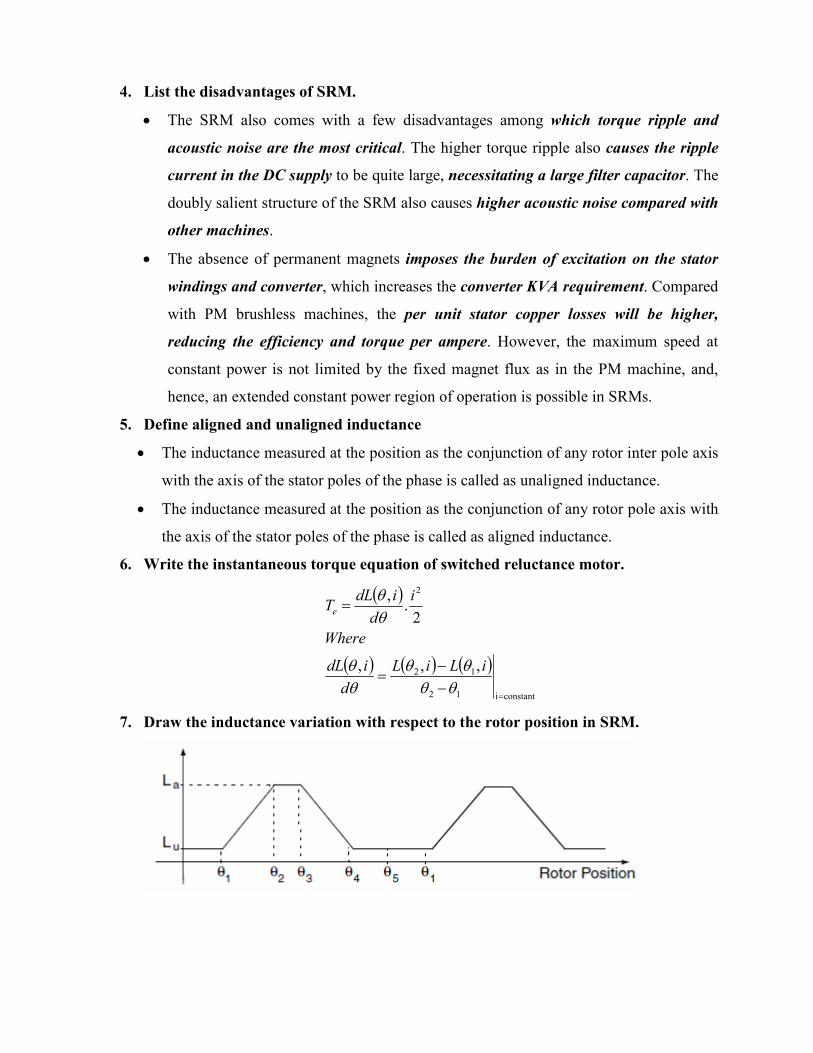
7. Draw the inductance variation with respect to the rotor position in SRM.
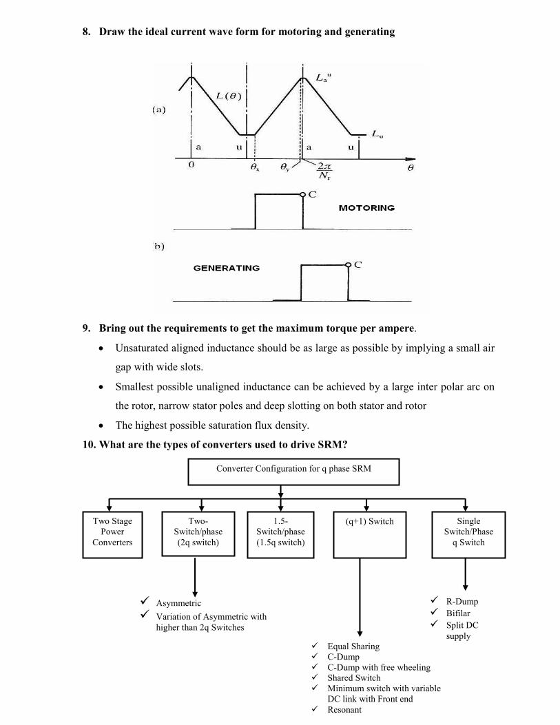
8. Draw the ideal current wave form for motoring and generating
9. Bring out the requirements to get the maximum torque per ampere.
• Unsaturated aligned inductance should be as large as possible by implying a small air
gap with wide slots.
• Smallest possible unaligned inductance can be achieved by a large inter polar arc on
the rotor, narrow stator poles and deep slotting on both stator and rotor
• The highest possible saturation flux density.
10. What are the types of converters used to drive SRM?
Converter Configuration for q phase SRM
Two Stage
Power
Converters
Two-
Switch/phase
(2q switch)
1.5-
Switch/phase
(1.5q switch)
(q+1) Switch Single
Switch/Phase
q Switch
� Equal Sharing
� C-Dump
� C-Dump with free wheeling
� Shared Switch
� Minimum switch with variable
DC link with Front end
� Resonant
� R-Dump
� Bifilar
� Split DC
supply
� Asymmetric
� Variation of Asymmetric with
higher than 2q Switches

11. Which makes the SRM to use unipolar controller circuit?
The torque is independent of the direction of the phase current which can therefore be
unidirectional. This permits the use of unipolar controller circuit for SRM.
12. Write the advantages of 2n transistor converter circuit
• This circuit provides the maximum control flexibility and efficiency, with a minimum
of passive components.
• By controlling the upper and lower transistors independently all possible firing angles
can be used.
• In small drives PWM control over the entire speed range is possible.
13. How the phase windings of the SRM are connected with the converter circuit and
compare it with the normal inverter with windings.
The phase winding is connected in between the two control switches on the same leg. But
in inverter the windings are connected from the mid points of adjacent phase legs. No
simultaneous switching ON process of the switches in the same leg.
14. State the advantages and limitations of bifilar winding converter circuit.
Advantages:
To reduce the number of switching devices bifilar winding is used.
Limitation:
• Double the numbers of connections are used.
• Poor utilization of copper
• Voltage spikes due to imperfect coupling
15. What is C dump converter circuit?
One capacitor is used in the circuit with one more phase to bleed the stored energy in the
capacitor.
16. What are the types of control method used to control SRM?
(a) Hysteresis Type
(b) Voltage PWM Type (duty-cycle control)
17. Draw the torque speed characteristics of SRM